EP2923607A1 - Method and system to divide a space - Google Patents
Method and system to divide a space Download PDFInfo
- Publication number
- EP2923607A1 EP2923607A1 EP15160929.4A EP15160929A EP2923607A1 EP 2923607 A1 EP2923607 A1 EP 2923607A1 EP 15160929 A EP15160929 A EP 15160929A EP 2923607 A1 EP2923607 A1 EP 2923607A1
- Authority
- EP
- European Patent Office
- Prior art keywords
- pin
- pins
- dividing element
- 7vii
- dividing
- Prior art date
- Legal status (The legal status is an assumption and is not a legal conclusion. Google has not performed a legal analysis and makes no representation as to the accuracy of the status listed.)
- Granted
Links
Images

Classifications
-
- A—HUMAN NECESSITIES
- A47—FURNITURE; DOMESTIC ARTICLES OR APPLIANCES; COFFEE MILLS; SPICE MILLS; SUCTION CLEANERS IN GENERAL
- A47B—TABLES; DESKS; OFFICE FURNITURE; CABINETS; DRAWERS; GENERAL DETAILS OF FURNITURE
- A47B88/00—Drawers for tables, cabinets or like furniture; Guides for drawers
- A47B88/90—Constructional details of drawers
- A47B88/969—Drawers having means for organising or sorting the content
- A47B88/975—Drawers having means for organising or sorting the content in the form of repositionable partition walls
-
- A—HUMAN NECESSITIES
- A47—FURNITURE; DOMESTIC ARTICLES OR APPLIANCES; COFFEE MILLS; SPICE MILLS; SUCTION CLEANERS IN GENERAL
- A47B—TABLES; DESKS; OFFICE FURNITURE; CABINETS; DRAWERS; GENERAL DETAILS OF FURNITURE
- A47B88/00—Drawers for tables, cabinets or like furniture; Guides for drawers
- A47B88/90—Constructional details of drawers
- A47B88/969—Drawers having means for organising or sorting the content
- A47B88/981—Drawers having means for organising or sorting the content in the form of vertical separation posts
Definitions
- the present patent application relates to a method and system to divide a space, in particular the inside of a drawer.
- a tray having a plurality of housings with sizes and shapes that are predetermined based on the products to be housed.
- a common cutlery tray to be used in a drawer of a kitchen cabinet comprises a tray made of a stiff material, which has a plurality of housings that are different from one another (in terms of shape and/or size and/or orientation), each of them being designed to house a respective type of product among: knives, forks, spoons, etc.
- a framework to be fixed on the inside of the drawer, which has a plurality squares with a predetermined size, each designed to house a respective product.
- the systems described above have the drawback that they are fixed.
- the drawback of the known systems described above is that they have a number of housings that cannot be changed and, in addition, each housing has a shape and/or orientation and/or size that cannot be changed.
- the number and/or the shape and/or the orientation of the housings cannot be changed based on the needs of the user. Hence, once a user has decided to use one of the systems described above, he/she must accept the pre-existing division of the spaces.
- the object of the present invention is to provide a method and a system to divide a space, in particular the inside of a drawer, which are able to overcome the drawback described above.
- the object of the present invention is to provide a dividing system that allows the number and/or the shape and/or the size and/or the orientation of the housings to be changed in a simple and quick fashion.
- a further object of the present invention is to provide a dividing system that is simple and cheap to be produced.
- number 1 indicates, as a whole, a system to divide a space, for example a drawer, comprising a plate 2 having an upper surface 3 and a lower surface 4.
- the plate 2 has, furthermore, a plurality of housings 5, which are uniformly distributed along lines and columns, so as to form a matrix of housings 5.
- the plate 2 comprises, furthermore, support bars 6, which project from the lower surface 4 of the plate 2.
- the system 1 comprises: a plurality of pins 7, each of which engages (as we will explain more in detail below) a respective housing 5 and projects from the upper surface 3 of the plate 2; and a plurality of dividing elements 8, each of which is fitted around two or more pins 7.
- Each pin 7 has the shape of a cylinder with a longitudinal axis A and comprises a separation ring 9, which radially projects from the pin 7 and longitudinally divides the pin 7 itself into an upper portion 10 and a lower portion 11. In use, the lower portion 11 is interposed between the upper portion 10 and the plate 2.
- Each pin 7 comprises, furthermore, a coupling element (known and not shown), which is designed to fix the pin 7 itself to the plate 2 by being inserted into a housing 5.
- Each pin 7 is connected to the plate 2 in a releasable manner.
- Each pin 7 can engage any housing 5 of the plate 2 without distinctions.
- Each pin 7 comprises, furthermore, a base abutment 12, which radially projects from the pin 7 and is interposed between the coupling element (in figure 1 it is inserted into the respective housing 5) and the lower portion 11. In use, the base abutment 12 is in contact with the plate 2.
- Each dividing element 8 is closed in a ring shape and comprises at least one portion made of an elastic material.
- each dividing element 8 is made of a flexible material.
- each dividing element 8 is an elastic material band closed in a ring shape. The width of each dividing element 8 corresponds to the longitudinal extension of an upper portion 10 and/or of a lower portion 11.
- the dividing element 8 can have a width that is substantially equal to the longitudinal extension of a pin 7 and, therefore, simultaneously cover both the upper portion 10 and the lower portion 11.
- the system 1 comprises a dividing element 81 fitted around the lower portions 11 of a group GI of four pins 71, 711, 7III, 7IV. Therefore, the dividing element 8I delimits, on the inside, an area SI with the shape of a rectangle, whose vertices are defined by the pins 71, 711, 7III, 7IV.
- the system 1 comprises a dividing element 8II fitted around the upper portions 10 of a group GII consisting of four pins 711, 7V, 7VI, 7VII.
- the dividing element 8II delimits an area SII with the shape of a rectangle, whose vertices are defined by the pins 7II, 7V, 7VI, 7VII.
- the area SII has an extension that is smaller that the extension of the area SI delimited by the dividing element 8I.
- the system 1 comprises, furthermore, a dividing element 8III fitted around the lower portions 11 of a group GIII consisting of two pins 7VII and 7VIII.
- a dividing element 8III fitted around the lower portions 11 of a group GIII consisting of two pins 7VII and 7VIII.
- the dividing element 8III delimits an area SIII with a substantially linear shape, whose ends are defined by the pins 7VII and 7VIII.
- the system 1 comprises, furthermore, a dividing element 8IV fitted around the upper portions 10 of a group GIV consisting of two pins 7111 and 7IX.
- a dividing element 8IV fitted around the upper portions 10 of a group GIV consisting of two pins 7111 and 7IX.
- the dividing element 8IV delimits an area SIV with a substantially linear shape, whose ends are defined by the pins 7111 and 7IX.
- Figure 2 shows a variant 101 of the system to divide a space, for example a drawer, in which the elements shared with figure 1 keep the same numbers, but in the order of hundreds.
- each pin 107 consists of a longitudinal body with an axis B and a substantially rectangular base shape with wounded corners.
- Each pin 107 comprises a separation element 109, which radially projects from the pin 107 and longitudinally divides the pin 107 itself into an upper portion 110 and a lower portion 111. In use, the lower portion 111 is interposed between the upper portion 110 and the plate 102.
- Each pin 107 comprises, furthermore, a coupling element (known and not shown), which is designed to couple the pin 107 itself to the plate 102 by being inserted into a housing 105.
- Each pin 107 comprises, furthermore, a base abutment 112, which radially projects from the pin 107 and is interposed between the coupling element (in figure 2 it is already inserted into the housing 105) and the lower portion 111. In use, the base abutment 112 is in contact with the plate 102.
- the system 101 comprises a dividing element 1081 fitted around the lower portions 111 of a group PI of four pins 1071, 10711, 107111, 107IV. Therefore, the dividing element 1081 delimits, on the inside, an area HI with the shape of a rectangle, whose vertices are defined by the pins 1071, 10711, 107111, 107IV.
- the system 101 comprises, furthermore, a dividing element 108II fitted around the upper portions 110 of a group PII consisting of four pins 107IV, 107V, 107VI, 107VII.
- the dividing element 108II delimits an area HII with the shape of a rectangle, whose vertices are defined by the pins 107IV, 107V, 107VI, 107VII.
- the area HII has an extension that is smaller that the extension of the area HI delimited by the dividing element 1081.
- the system 101 comprises, furthermore, a dividing element 108111 fitted around the upper portions 110 of a group PIII comprising two pins 1071 and 107VIII
- the pin 1071 is engaged both by the dividing element 108II and by the dividing element 108111.
- the dividing element 108111 delimits an area HIII with the shape of a slit, whose ends are defined by the pins 1071 and 107VIII.
- the pins can have different shapes; furthermore, the pin can be divided into two longitudinal portions.
- the pins 7 or 107 can be arranged so as to delimit areas with shapes that are different from the ones shown herein, for example they can have the shape of a triangle, a pentagon or a rhombus. Te matrix of housings 5 or 105 allows users to create a large number of housings that are different in terms of shape and size.
- the plate 2 or 102 is inserted into the space to be divided, for example it is caused to rest with the bases 6 or 106 on the inside of a drawer. Then, each pin 7 or 107 of a group G or P is fixed to the plate 2 or 102 by inserting it into respective housings 5 or 105, which are chosen among all the housings 5 or 105 of the plate 2 or 102 based on the shape and size of the area S or H to be delimited with the dividing element 8 or 108.
- a dividing element 8 or 108 is stretched and fitted around all the pins 7 or 107 of the respective group G or P, so that the pins 7 or 107 substantially define the vertices of the geometrical figure delimited by the dividing element 8 or 108.
- the dividing element 8 or 108 can be fitted around the upper portion 10 or 110 or around the lower portion 11 or 111 based on the desired height of the area S to be delimited.
- a single pin 7 (107) can simultaneously be part of two groups G (P) by engaging the upper portion 10 (110) with a dividing element 8 (108) and the lower portion 11 (111) with another dividing element 8 (108).
- the method and the system described above allow users to divide different areas G (H) based on their needs.
- the number, the shape and the size of the areas G (H) of each system described above can change according to the actual needs of the person using it.
- a space dividing system and method of the type described above find advantageous application in drawers/chest of drawers used to hold packages of different types, such as, for example, bags, bottles, boxes or loose products.
- a system and method of the type described above are suited to be applied on the inside of drawers/chest of drawers for kitchen cabinets, bathroom cabinets, living furniture and other furniture.
- the system described above is simple and cheap to be produced; furthermore, the method described above can easily be applied, since end users can very easily change the arrangement of the pins 7 or 107 and of the dividing elements 8 or 108 based on their actual needs.
Landscapes
- Drawers Of Furniture (AREA)
Abstract
Description
- The present patent application relates to a method and system to divide a space, in particular the inside of a drawer.
- In order to divide the inner space of a drawer, it is known to use a tray having a plurality of housings with sizes and shapes that are predetermined based on the products to be housed.
- For example, a common cutlery tray to be used in a drawer of a kitchen cabinet comprises a tray made of a stiff material, which has a plurality of housings that are different from one another (in terms of shape and/or size and/or orientation), each of them being designed to house a respective type of product among: knives, forks, spoons, etc.
- Alternatively, it is known to use a framework to be fixed on the inside of the drawer, which has a plurality squares with a predetermined size, each designed to house a respective product.
- The systems described above have the drawback that they are fixed. In other words, the drawback of the known systems described above is that they have a number of housings that cannot be changed and, in addition, each housing has a shape and/or orientation and/or size that cannot be changed.
- Therefore, in known systems, the number and/or the shape and/or the orientation of the housings cannot be changed based on the needs of the user. Hence, once a user has decided to use one of the systems described above, he/she must accept the pre-existing division of the spaces.
- The object of the present invention is to provide a method and a system to divide a space, in particular the inside of a drawer, which are able to overcome the drawback described above. In other words, the object of the present invention is to provide a dividing system that allows the number and/or the shape and/or the size and/or the orientation of the housings to be changed in a simple and quick fashion. Furthermore, a further object of the present invention is to provide a dividing system that is simple and cheap to be produced.
- According to the present invention, there is provided a method and a system to divide spaces according to the appended claims.
- The invention will now be described with reference to the accompanying drawings, which show non-limiting embodiments thereof, wherein:
-
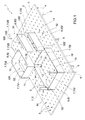
figure 1 shows an axonometric projection of a dividing system according to the present invention; and -
figure 2 is similar tofigure 1 and shows a variant of the dividing system offigure 1 . - In
figure 1 ,number 1 indicates, as a whole, a system to divide a space, for example a drawer, comprising aplate 2 having anupper surface 3 and alower surface 4. Theplate 2 has, furthermore, a plurality ofhousings 5, which are uniformly distributed along lines and columns, so as to form a matrix ofhousings 5. Theplate 2 comprises, furthermore,support bars 6, which project from thelower surface 4 of theplate 2. - According to
figure 1 , thesystem 1 comprises: a plurality of pins 7, each of which engages (as we will explain more in detail below) arespective housing 5 and projects from theupper surface 3 of theplate 2; and a plurality of dividing elements 8, each of which is fitted around two or more pins 7. - Each pin 7 has the shape of a cylinder with a longitudinal axis A and comprises a
separation ring 9, which radially projects from the pin 7 and longitudinally divides the pin 7 itself into anupper portion 10 and alower portion 11. In use, thelower portion 11 is interposed between theupper portion 10 and theplate 2. - Each pin 7 comprises, furthermore, a coupling element (known and not shown), which is designed to fix the pin 7 itself to the
plate 2 by being inserted into ahousing 5. Each pin 7 is connected to theplate 2 in a releasable manner. Each pin 7 can engage anyhousing 5 of theplate 2 without distinctions. - Each pin 7 comprises, furthermore, a
base abutment 12, which radially projects from the pin 7 and is interposed between the coupling element (infigure 1 it is inserted into the respective housing 5) and thelower portion 11. In use, thebase abutment 12 is in contact with theplate 2. - Each dividing element 8 is closed in a ring shape and comprises at least one portion made of an elastic material. Preferably, each dividing element 8 is made of a flexible material. According to the figures, each dividing element 8 is an elastic material band closed in a ring shape. The width of each dividing element 8 corresponds to the longitudinal extension of an
upper portion 10 and/or of alower portion 11. - According to a variant that is not shown herein, the dividing element 8 can have a width that is substantially equal to the longitudinal extension of a pin 7 and, therefore, simultaneously cover both the
upper portion 10 and thelower portion 11. - According to
figure 1 , thesystem 1 comprises a dividing element 81 fitted around thelower portions 11 of a group GI of four pins 71, 711, 7III, 7IV. Therefore, the dividing element 8I delimits, on the inside, an area SI with the shape of a rectangle, whose vertices are defined by the pins 71, 711, 7III, 7IV. - The
system 1 comprises a dividing element 8II fitted around theupper portions 10 of a group GII consisting of four pins 711, 7V, 7VI, 7VII. We would like to point out that the pin 711 is engaged both by the dividing element 8I and by the dividing element 8II. The dividing element 8II delimits an area SII with the shape of a rectangle, whose vertices are defined by the pins 7II, 7V, 7VI, 7VII. We would like to point out that the area SII has an extension that is smaller that the extension of the area SI delimited by the dividing element 8I. - The
system 1 comprises, furthermore, a dividing element 8III fitted around thelower portions 11 of a group GIII consisting of two pins 7VII and 7VIII. We would like to point out that the pin 7VII is engaged both by the dividing element 8II and by the dividing element 8III. The dividing element 8III delimits an area SIII with a substantially linear shape, whose ends are defined by the pins 7VII and 7VIII. - The
system 1 comprises, furthermore, a dividing element 8IV fitted around theupper portions 10 of a group GIV consisting of two pins 7111 and 7IX. We would like to point out that the pin 7111 is engaged both by the dividing element 8I and by the dividing element 8IV. The dividing element 8IV delimits an area SIV with a substantially linear shape, whose ends are defined by the pins 7111 and 7IX. -
Figure 2 shows avariant 101 of the system to divide a space, for example a drawer, in which the elements shared withfigure 1 keep the same numbers, but in the order of hundreds. - According to
figure 2 , each pin 107 consists of a longitudinal body with an axis B and a substantially rectangular base shape with wounded corners. Each pin 107 comprises aseparation element 109, which radially projects from the pin 107 and longitudinally divides the pin 107 itself into anupper portion 110 and alower portion 111. In use, thelower portion 111 is interposed between theupper portion 110 and theplate 102. - Each pin 107 comprises, furthermore, a coupling element (known and not shown), which is designed to couple the pin 107 itself to the
plate 102 by being inserted into ahousing 105. Each pin 107 comprises, furthermore, a base abutment 112, which radially projects from the pin 107 and is interposed between the coupling element (infigure 2 it is already inserted into the housing 105) and thelower portion 111. In use, the base abutment 112 is in contact with theplate 102. - According to
figure 2 , thesystem 101 comprises a dividing element 1081 fitted around thelower portions 111 of a group PI of four pins 1071, 10711, 107111, 107IV. Therefore, the dividing element 1081 delimits, on the inside, an area HI with the shape of a rectangle, whose vertices are defined by the pins 1071, 10711, 107111, 107IV. - The
system 101 comprises, furthermore, a dividing element 108II fitted around theupper portions 110 of a group PII consisting of four pins 107IV, 107V, 107VI, 107VII. We would like to point out that the pin 107IV is engaged both by the dividing element 1081 and by the dividing element 108II. The dividing element 108II delimits an area HII with the shape of a rectangle, whose vertices are defined by the pins 107IV, 107V, 107VI, 107VII. We would like to point out that the area HII has an extension that is smaller that the extension of the area HI delimited by the dividing element 1081. - The
system 101 comprises, furthermore, a dividing element 108111 fitted around theupper portions 110 of a group PIII comprising two pins 1071 and 107VIII The pin 1071 is engaged both by the dividing element 108II and by the dividing element 108111. The dividing element 108111 delimits an area HIII with the shape of a slit, whose ends are defined by the pins 1071 and 107VIII. - According to variants that are not shown herein, the pins can have different shapes; furthermore, the pin can be divided into two longitudinal portions. The pins 7 or 107 can be arranged so as to delimit areas with shapes that are different from the ones shown herein, for example they can have the shape of a triangle, a pentagon or a rhombus. Te matrix of
housings - In use, the
plate bases plate respective housings housings plate - Subsequently, a dividing element 8 or 108 is stretched and fitted around all the pins 7 or 107 of the respective group G or P, so that the pins 7 or 107 substantially define the vertices of the geometrical figure delimited by the dividing element 8 or 108.
- The dividing element 8 or 108 can be fitted around the
upper portion lower portion - The procedure described above can be repeated many times in order to create a plurality of different areas according to the needs. Should a housing created with the aforesaid method not be needed by the user any longer, it is sufficient to disengage the dividing element 8 (108) from the respective pins 7 (107) and, similarly, disengage the pins 7 (107) from the plate 2 (102). Then, other housings G (H) can be made with same pins 7 (107) used before.
- The method and the system described above allow users to divide different areas G (H) based on their needs. In other words, the number, the shape and the size of the areas G (H) of each system described above can change according to the actual needs of the person using it.
- A space dividing system and method of the type described above find advantageous application in drawers/chest of drawers used to hold packages of different types, such as, for example, bags, bottles, boxes or loose products. By way of example, a system and method of the type described above are suited to be applied on the inside of drawers/chest of drawers for kitchen cabinets, bathroom cabinets, living furniture and other furniture.
- The system described above is simple and cheap to be produced; furthermore, the method described above can easily be applied, since end users can very easily change the arrangement of the pins 7 or 107 and of the dividing elements 8 or 108 based on their actual needs.
Claims (10)
- A method to divide a space, in particular the inside of a drawer, by means of a system (1; 101) comprising a first pin (7VII; 7111; 107I), a second pin (7VIII; 7IX; 107VIII), and a dividing element (8111; 8IV; 108III), which has the shape of a ring and is at least partially made of a flexible and/or elastic material; the method comprising the steps of:- positioning the first pin (7VII; 7111; 1071) in a first position;- positioning the second pin (7VIII; 7IX; 107VIII) in a second position;- stretching the dividing element (8111; 8IV; 108111) by means of the first pin (7VII; 7111; 1071) and the second pin (7VIII; 7IX; 107VIII), so as to define an area (SIII; SIV; HIII) inside said dividing element (8111; 8IV; 108111); wherein the size of said area (SIII; SIV; HIII) is defined by the position of the first pin (7VII; 7111; 1071) relative to the second pin (7VIII; 7IX; 107VIII), the dividing element (8111; 8IV; 108111) being fitted around both the first pin (7VII; 7111; 1071) and the second pin (7VIII; 7IX; 107VIII).
- A method to divide a space according to claim 1 by means of a system (1; 101) comprising a plurality of pins (71, 711, 7111, 7IV; 711, 7V, 7VI, 7VII; 1071, 10711, 107III, 107IV; 107IV, 107V, 107VI, 107VII) and a dividing element (81; 811; 1081; 108111), which has the shape of a ring and is at least partially made of a flexible and/or elastic material; the method comprising the steps of:- positioning each pin (71, 711, 7III, 7IV; 711, 7V, 7VI, 7VII; 1071, 10711, 107111, 107IV; 107IV, 107V, 107VI, 107VII) in a respective position;- stretching the dividing element (81; 811; 1081; 108111) by means of each pin (71, 711, 7III, 7IV; 711, 7V, 7VI, 7VII; 1071, 10711, 107111, 107IV; 107IV, 107V, 107VI, 107VII), so as to define an area (SI; SII; HI; HII) inside said dividing element (81; 811; 1081; 108111); wherein the shape and the size of said area (SI; SII; HI; HII) depend on the mutual position of the pins (71, 711, 7111, 7IV; 711, 7V, 7VI, 7VII; 1071, 10711, 107111, 107IV; 107IV, 107V, 107VI, 107VII).
- A method according to claim 1 or 2, wherein the system (1; 101) comprises a plurality of pins (7; 107) and a plurality of dividing elements (8; 108); wherein each dividing element (8; 108) is associated with a group of pins (G; P) of two or more pins (7; 107); the method being characterised in that it comprises the steps of:- positioning each pin (7; 107) of each group of pins (G; P) in a respective position;- stretching each dividing element (8; 108) by means of each pin (7; 107) of the respective group of pins (G; P), so as to define a plurality of areas inside said dividing elements (8; 108); wherein the number of areas is determined by the number of dividing elements (8; 108); wherein the shape and the size of each area (S; H) depend on the mutual position of the pins (7; 107) of the respective group of pins (G; P).
- A method according to claim 3, wherein each pin (7; 107) comprises a first portion (10; 110) and a second portion (11; 111), each of which is suited to interact with a dividing element (8; 108); wherein the step of stretching each dividing element (8; 108) comprises the sub-step of fitting a first dividing element (811; 8IV; 108II; 108111) around the first portion (10; 110) and, respectively, a second dividing element (81; 8111; 1081) around the second portion (11; 111) of a pin (711; 7111; 7VII; 107IV; 1071), which simultaneously belongs to two groups of pins (GI, GII; GI, GIV; GII, GIII; PI, PII; PI, PIII).
- A method according to any of the previous claims, wherein the system (1; 101) comprises a plate (2; 102) having a plurality of housings (5; 105), wherein the step of positioning each pin (7; 107) comprises the sub-step of connecting each pin (7; 107) to a respective housing (5; 105) in a releasable manner.
- A system to divide a space, in particular the inside of a drawer, comprising a first and a second pin (7; 107) and a dividing element (8; 108), which has the shape of a ring and is at least partially made of a flexible and/or elastic material; wherein the pins (7; 107) are arranged, in use, one next to the other in respective positions and stretch the dividing element (8; 108), which is partially fitted around both pins (7; 107), thus delimiting an area (S; H) on the inside.
- A system according to claim 6 and comprising a plurality of pins (7; 107), which make up a group of pins (G; P), and a dividing element (8; 108); wherein, in use, the dividing element (8; 108) is at least partially fitted around each pin (7; 107) of said group of pins (G; P); wherein each pin (7; 107) of the group of pins (G; P) defines a vertex of the geometric shape delimited by the dividing element (8; 108).
- A system according to claim 7 and comprising a plurality of dividing elements (8; 108) and a plurality of group of pins (G; P); wherein each pin (7; 107) comprises a first portion (10; 110) and a second portion (11; 111), each of which is suited to be engaged by a respective dividing element (8; 108).
- A system according to any of the claims from 6 to 8 and comprising a plate (2; 102) having a plurality of housings (5; 105); each pin (7; 107) comprising a coupling element, which is suited to be coupled to a respective housing in a releasable manner, so as to fix the pin (7; 107) to the plate (2; 102).
- A system according to claim 9, wherein the housings (5; 105) are arranged along lines and columns, so as to form a matrix of housings.
Applications Claiming Priority (1)
| Application Number | Priority Date | Filing Date | Title |
|---|---|---|---|
| ITBO20140158 | 2014-03-25 |
Publications (3)
| Publication Number | Publication Date |
|---|---|
| EP2923607A1 true EP2923607A1 (en) | 2015-09-30 |
| EP2923607A9 EP2923607A9 (en) | 2016-01-13 |
| EP2923607B1 EP2923607B1 (en) | 2021-05-05 |
Family
ID=50943367
Family Applications (1)
| Application Number | Title | Priority Date | Filing Date |
|---|---|---|---|
| EP15160929.4A Active EP2923607B1 (en) | 2014-03-25 | 2015-03-25 | Method and system to divide a space |
Country Status (1)
| Country | Link |
|---|---|
| EP (1) | EP2923607B1 (en) |
Citations (1)
| Publication number | Priority date | Publication date | Assignee | Title |
|---|---|---|---|---|
| DE202012012498U1 (en) * | 2012-04-12 | 2013-07-15 | Bulthaup Gmbh & Co. Kg | classification system |
Family Cites Families (1)
| Publication number | Priority date | Publication date | Assignee | Title |
|---|---|---|---|---|
| EP1926917A1 (en) * | 2005-09-09 | 2008-06-04 | Eckhart Hüser | System and method for forming subdivisions on storage surfaces |
-
2015
- 2015-03-25 EP EP15160929.4A patent/EP2923607B1/en active Active
Patent Citations (1)
| Publication number | Priority date | Publication date | Assignee | Title |
|---|---|---|---|---|
| DE202012012498U1 (en) * | 2012-04-12 | 2013-07-15 | Bulthaup Gmbh & Co. Kg | classification system |
Also Published As
| Publication number | Publication date |
|---|---|
| EP2923607B1 (en) | 2021-05-05 |
| EP2923607A9 (en) | 2016-01-13 |
Similar Documents
| Publication | Publication Date | Title |
|---|---|---|
| USD788584S1 (en) | Stand | |
| US4128064A (en) | Free standing shelves | |
| US9636429B2 (en) | Tray and bracket system and related methods | |
| US3543699A (en) | Display rack with spiral shelves | |
| EP3138440B1 (en) | Modular structure for a tower-type display stand made of cardboard | |
| TWM459785U (en) | Expandable frame structure | |
| US10238208B2 (en) | Modular food product display stand | |
| US10130104B2 (en) | Variable length cooking divider | |
| Darties et al. | Completely independent spanning trees in some regular graphs | |
| EP2923607B1 (en) | Method and system to divide a space | |
| EP4144261A1 (en) | Foldable flower arranging device for a vase | |
| US9743756B2 (en) | Piece of furniture having a convertible work surface | |
| USD918416S1 (en) | Set of drawer trays for medical and laboratory equipment | |
| Šobot | |˜-divisibility of ultrafilters | |
| Dilcher et al. | Infinite products involving Dirichlet characters and cyclotomic polynomials | |
| HUE067422T2 (en) | Arrangement comprising a shelf and at least one separating element | |
| KR101038842B1 (en) | Cake pedestal | |
| GB2137871A (en) | Modular storage racks | |
| KR20110000759U (en) | Divider for furniture | |
| KR20160057010A (en) | Adjustable shelf | |
| TH185919S (en) | Chest of drawers | |
| CN105310369B (en) | The displaying device of sample for leather, fabric etc. | |
| GB2097664A (en) | Base for a stand | |
| US20130214035A1 (en) | Reusable Paper Pan | |
| Lengvarszky | An Origami Puzzle of Intersecting Cubes |
Legal Events
| Date | Code | Title | Description |
|---|---|---|---|
| PUAI | Public reference made under article 153(3) epc to a published international application that has entered the european phase |
Free format text: ORIGINAL CODE: 0009012 |
|
| AK | Designated contracting states |
Kind code of ref document: A1 Designated state(s): AL AT BE BG CH CY CZ DE DK EE ES FI FR GB GR HR HU IE IS IT LI LT LU LV MC MK MT NL NO PL PT RO RS SE SI SK SM TR |
|
| AX | Request for extension of the european patent |
Extension state: BA ME |
|
| 17P | Request for examination filed |
Effective date: 20160329 |
|
| RBV | Designated contracting states (corrected) |
Designated state(s): AL AT BE BG CH CY CZ DE DK EE ES FI FR GB GR HR HU IE IS IT LI LT LU LV MC MK MT NL NO PL PT RO RS SE SI SK SM TR |
|
| RAP1 | Party data changed (applicant data changed or rights of an application transferred) |
Owner name: GOLLINUCCI, GIACOMO |
|
| RIN1 | Information on inventor provided before grant (corrected) |
Inventor name: GOLLINUCCI, GIACOMO |
|
| REG | Reference to a national code |
Ref country code: DE Ref legal event code: R079 Ref document number: 602015068873 Country of ref document: DE Free format text: PREVIOUS MAIN CLASS: A47B0088200000 Ipc: A47B0088975000 |
|
| RIC1 | Information provided on ipc code assigned before grant |
Ipc: A47B 88/975 20170101AFI20200806BHEP |
|
| GRAP | Despatch of communication of intention to grant a patent |
Free format text: ORIGINAL CODE: EPIDOSNIGR1 |
|
| STAA | Information on the status of an ep patent application or granted ep patent |
Free format text: STATUS: GRANT OF PATENT IS INTENDED |
|
| INTG | Intention to grant announced |
Effective date: 20201014 |
|
| GRAS | Grant fee paid |
Free format text: ORIGINAL CODE: EPIDOSNIGR3 |
|
| GRAA | (expected) grant |
Free format text: ORIGINAL CODE: 0009210 |
|
| STAA | Information on the status of an ep patent application or granted ep patent |
Free format text: STATUS: THE PATENT HAS BEEN GRANTED |
|
| AK | Designated contracting states |
Kind code of ref document: B1 Designated state(s): AL AT BE BG CH CY CZ DE DK EE ES FI FR GB GR HR HU IE IS IT LI LT LU LV MC MK MT NL NO PL PT RO RS SE SI SK SM TR |
|
| REG | Reference to a national code |
Ref country code: GB Ref legal event code: FG4D |
|
| REG | Reference to a national code |
Ref country code: CH Ref legal event code: EP |
|
| REG | Reference to a national code |
Ref country code: AT Ref legal event code: REF Ref document number: 1388735 Country of ref document: AT Kind code of ref document: T Effective date: 20210515 |
|
| REG | Reference to a national code |
Ref country code: IE Ref legal event code: FG4D |
|
| REG | Reference to a national code |
Ref country code: DE Ref legal event code: R096 Ref document number: 602015068873 Country of ref document: DE |
|
| REG | Reference to a national code |
Ref country code: LT Ref legal event code: MG9D |
|
| REG | Reference to a national code |
Ref country code: AT Ref legal event code: MK05 Ref document number: 1388735 Country of ref document: AT Kind code of ref document: T Effective date: 20210505 |
|
| PG25 | Lapsed in a contracting state [announced via postgrant information from national office to epo] |
Ref country code: LT Free format text: LAPSE BECAUSE OF FAILURE TO SUBMIT A TRANSLATION OF THE DESCRIPTION OR TO PAY THE FEE WITHIN THE PRESCRIBED TIME-LIMIT Effective date: 20210505 Ref country code: FI Free format text: LAPSE BECAUSE OF FAILURE TO SUBMIT A TRANSLATION OF THE DESCRIPTION OR TO PAY THE FEE WITHIN THE PRESCRIBED TIME-LIMIT Effective date: 20210505 Ref country code: BG Free format text: LAPSE BECAUSE OF FAILURE TO SUBMIT A TRANSLATION OF THE DESCRIPTION OR TO PAY THE FEE WITHIN THE PRESCRIBED TIME-LIMIT Effective date: 20210805 Ref country code: AT Free format text: LAPSE BECAUSE OF FAILURE TO SUBMIT A TRANSLATION OF THE DESCRIPTION OR TO PAY THE FEE WITHIN THE PRESCRIBED TIME-LIMIT Effective date: 20210505 Ref country code: HR Free format text: LAPSE BECAUSE OF FAILURE TO SUBMIT A TRANSLATION OF THE DESCRIPTION OR TO PAY THE FEE WITHIN THE PRESCRIBED TIME-LIMIT Effective date: 20210505 |
|
| PG25 | Lapsed in a contracting state [announced via postgrant information from national office to epo] |
Ref country code: RS Free format text: LAPSE BECAUSE OF FAILURE TO SUBMIT A TRANSLATION OF THE DESCRIPTION OR TO PAY THE FEE WITHIN THE PRESCRIBED TIME-LIMIT Effective date: 20210505 Ref country code: SE Free format text: LAPSE BECAUSE OF FAILURE TO SUBMIT A TRANSLATION OF THE DESCRIPTION OR TO PAY THE FEE WITHIN THE PRESCRIBED TIME-LIMIT Effective date: 20210505 Ref country code: ES Free format text: LAPSE BECAUSE OF FAILURE TO SUBMIT A TRANSLATION OF THE DESCRIPTION OR TO PAY THE FEE WITHIN THE PRESCRIBED TIME-LIMIT Effective date: 20210505 Ref country code: PT Free format text: LAPSE BECAUSE OF FAILURE TO SUBMIT A TRANSLATION OF THE DESCRIPTION OR TO PAY THE FEE WITHIN THE PRESCRIBED TIME-LIMIT Effective date: 20210906 Ref country code: NO Free format text: LAPSE BECAUSE OF FAILURE TO SUBMIT A TRANSLATION OF THE DESCRIPTION OR TO PAY THE FEE WITHIN THE PRESCRIBED TIME-LIMIT Effective date: 20210805 Ref country code: PL Free format text: LAPSE BECAUSE OF FAILURE TO SUBMIT A TRANSLATION OF THE DESCRIPTION OR TO PAY THE FEE WITHIN THE PRESCRIBED TIME-LIMIT Effective date: 20210505 Ref country code: LV Free format text: LAPSE BECAUSE OF FAILURE TO SUBMIT A TRANSLATION OF THE DESCRIPTION OR TO PAY THE FEE WITHIN THE PRESCRIBED TIME-LIMIT Effective date: 20210505 Ref country code: GR Free format text: LAPSE BECAUSE OF FAILURE TO SUBMIT A TRANSLATION OF THE DESCRIPTION OR TO PAY THE FEE WITHIN THE PRESCRIBED TIME-LIMIT Effective date: 20210806 Ref country code: IS Free format text: LAPSE BECAUSE OF FAILURE TO SUBMIT A TRANSLATION OF THE DESCRIPTION OR TO PAY THE FEE WITHIN THE PRESCRIBED TIME-LIMIT Effective date: 20210905 |
|
| REG | Reference to a national code |
Ref country code: NL Ref legal event code: MP Effective date: 20210505 |
|
| PG25 | Lapsed in a contracting state [announced via postgrant information from national office to epo] |
Ref country code: NL Free format text: LAPSE BECAUSE OF FAILURE TO SUBMIT A TRANSLATION OF THE DESCRIPTION OR TO PAY THE FEE WITHIN THE PRESCRIBED TIME-LIMIT Effective date: 20210505 |
|
| PG25 | Lapsed in a contracting state [announced via postgrant information from national office to epo] |
Ref country code: SM Free format text: LAPSE BECAUSE OF FAILURE TO SUBMIT A TRANSLATION OF THE DESCRIPTION OR TO PAY THE FEE WITHIN THE PRESCRIBED TIME-LIMIT Effective date: 20210505 Ref country code: SK Free format text: LAPSE BECAUSE OF FAILURE TO SUBMIT A TRANSLATION OF THE DESCRIPTION OR TO PAY THE FEE WITHIN THE PRESCRIBED TIME-LIMIT Effective date: 20210505 Ref country code: DK Free format text: LAPSE BECAUSE OF FAILURE TO SUBMIT A TRANSLATION OF THE DESCRIPTION OR TO PAY THE FEE WITHIN THE PRESCRIBED TIME-LIMIT Effective date: 20210505 Ref country code: CZ Free format text: LAPSE BECAUSE OF FAILURE TO SUBMIT A TRANSLATION OF THE DESCRIPTION OR TO PAY THE FEE WITHIN THE PRESCRIBED TIME-LIMIT Effective date: 20210505 Ref country code: EE Free format text: LAPSE BECAUSE OF FAILURE TO SUBMIT A TRANSLATION OF THE DESCRIPTION OR TO PAY THE FEE WITHIN THE PRESCRIBED TIME-LIMIT Effective date: 20210505 Ref country code: RO Free format text: LAPSE BECAUSE OF FAILURE TO SUBMIT A TRANSLATION OF THE DESCRIPTION OR TO PAY THE FEE WITHIN THE PRESCRIBED TIME-LIMIT Effective date: 20210505 |
|
| REG | Reference to a national code |
Ref country code: DE Ref legal event code: R097 Ref document number: 602015068873 Country of ref document: DE |
|
| PLBE | No opposition filed within time limit |
Free format text: ORIGINAL CODE: 0009261 |
|
| STAA | Information on the status of an ep patent application or granted ep patent |
Free format text: STATUS: NO OPPOSITION FILED WITHIN TIME LIMIT |
|
| 26N | No opposition filed |
Effective date: 20220208 |
|
| PG25 | Lapsed in a contracting state [announced via postgrant information from national office to epo] |
Ref country code: IS Free format text: LAPSE BECAUSE OF FAILURE TO SUBMIT A TRANSLATION OF THE DESCRIPTION OR TO PAY THE FEE WITHIN THE PRESCRIBED TIME-LIMIT Effective date: 20210905 Ref country code: AL Free format text: LAPSE BECAUSE OF FAILURE TO SUBMIT A TRANSLATION OF THE DESCRIPTION OR TO PAY THE FEE WITHIN THE PRESCRIBED TIME-LIMIT Effective date: 20210505 |
|
| PG25 | Lapsed in a contracting state [announced via postgrant information from national office to epo] |
Ref country code: IT Free format text: LAPSE BECAUSE OF FAILURE TO SUBMIT A TRANSLATION OF THE DESCRIPTION OR TO PAY THE FEE WITHIN THE PRESCRIBED TIME-LIMIT Effective date: 20210505 |
|
| PG25 | Lapsed in a contracting state [announced via postgrant information from national office to epo] |
Ref country code: MC Free format text: LAPSE BECAUSE OF FAILURE TO SUBMIT A TRANSLATION OF THE DESCRIPTION OR TO PAY THE FEE WITHIN THE PRESCRIBED TIME-LIMIT Effective date: 20210505 |
|
| REG | Reference to a national code |
Ref country code: CH Ref legal event code: PL |
|
| REG | Reference to a national code |
Ref country code: DE Ref legal event code: R081 Ref document number: 602015068873 Country of ref document: DE Owner name: GOLLINUCCI S.R.L., IT Free format text: FORMER OWNER: GOLLINUCCI, GIACOMO, CESENA, IT |
|
| REG | Reference to a national code |
Ref country code: BE Ref legal event code: MM Effective date: 20220331 |
|
| REG | Reference to a national code |
Ref country code: GB Ref legal event code: 732E Free format text: REGISTERED BETWEEN 20221124 AND 20221130 |
|
| PG25 | Lapsed in a contracting state [announced via postgrant information from national office to epo] |
Ref country code: LU Free format text: LAPSE BECAUSE OF NON-PAYMENT OF DUE FEES Effective date: 20220325 Ref country code: LI Free format text: LAPSE BECAUSE OF NON-PAYMENT OF DUE FEES Effective date: 20220331 Ref country code: IE Free format text: LAPSE BECAUSE OF NON-PAYMENT OF DUE FEES Effective date: 20220325 Ref country code: CH Free format text: LAPSE BECAUSE OF NON-PAYMENT OF DUE FEES Effective date: 20220331 |
|
| PG25 | Lapsed in a contracting state [announced via postgrant information from national office to epo] |
Ref country code: BE Free format text: LAPSE BECAUSE OF NON-PAYMENT OF DUE FEES Effective date: 20220331 |
|
| PG25 | Lapsed in a contracting state [announced via postgrant information from national office to epo] |
Ref country code: HU Free format text: LAPSE BECAUSE OF FAILURE TO SUBMIT A TRANSLATION OF THE DESCRIPTION OR TO PAY THE FEE WITHIN THE PRESCRIBED TIME-LIMIT; INVALID AB INITIO Effective date: 20150325 |
|
| PG25 | Lapsed in a contracting state [announced via postgrant information from national office to epo] |
Ref country code: MK Free format text: LAPSE BECAUSE OF FAILURE TO SUBMIT A TRANSLATION OF THE DESCRIPTION OR TO PAY THE FEE WITHIN THE PRESCRIBED TIME-LIMIT Effective date: 20210505 Ref country code: CY Free format text: LAPSE BECAUSE OF FAILURE TO SUBMIT A TRANSLATION OF THE DESCRIPTION OR TO PAY THE FEE WITHIN THE PRESCRIBED TIME-LIMIT Effective date: 20210505 |
|
| PG25 | Lapsed in a contracting state [announced via postgrant information from national office to epo] |
Ref country code: MT Free format text: LAPSE BECAUSE OF FAILURE TO SUBMIT A TRANSLATION OF THE DESCRIPTION OR TO PAY THE FEE WITHIN THE PRESCRIBED TIME-LIMIT Effective date: 20210505 |
|
| PG25 | Lapsed in a contracting state [announced via postgrant information from national office to epo] |
Ref country code: TR Free format text: LAPSE BECAUSE OF FAILURE TO SUBMIT A TRANSLATION OF THE DESCRIPTION OR TO PAY THE FEE WITHIN THE PRESCRIBED TIME-LIMIT Effective date: 20210505 |
|
| PGFP | Annual fee paid to national office [announced via postgrant information from national office to epo] |
Ref country code: GB Payment date: 20260304 Year of fee payment: 12 |
|
| PGFP | Annual fee paid to national office [announced via postgrant information from national office to epo] |
Ref country code: DE Payment date: 20260320 Year of fee payment: 12 |
|
| PGFP | Annual fee paid to national office [announced via postgrant information from national office to epo] |
Ref country code: FR Payment date: 20260323 Year of fee payment: 12 |