EP2923538A1 - Locking construction for agricultural machines - Google Patents
Locking construction for agricultural machines Download PDFInfo
- Publication number
- EP2923538A1 EP2923538A1 EP14200008.2A EP14200008A EP2923538A1 EP 2923538 A1 EP2923538 A1 EP 2923538A1 EP 14200008 A EP14200008 A EP 14200008A EP 2923538 A1 EP2923538 A1 EP 2923538A1
- Authority
- EP
- European Patent Office
- Prior art keywords
- bracket
- framework
- counter
- locking
- construction
- Prior art date
- Legal status (The legal status is an assumption and is not a legal conclusion. Google has not performed a legal analysis and makes no representation as to the accuracy of the status listed.)
- Granted
Links
Images




Classifications
-
- A—HUMAN NECESSITIES
- A01—AGRICULTURE; FORESTRY; ANIMAL HUSBANDRY; HUNTING; TRAPPING; FISHING
- A01B—SOIL WORKING IN AGRICULTURE OR FORESTRY; PARTS, DETAILS, OR ACCESSORIES OF AGRICULTURAL MACHINES OR IMPLEMENTS, IN GENERAL
- A01B23/00—Elements, tools, or details of harrows
- A01B23/02—Teeth; Fixing the teeth
-
- A—HUMAN NECESSITIES
- A01—AGRICULTURE; FORESTRY; ANIMAL HUSBANDRY; HUNTING; TRAPPING; FISHING
- A01B—SOIL WORKING IN AGRICULTURE OR FORESTRY; PARTS, DETAILS, OR ACCESSORIES OF AGRICULTURAL MACHINES OR IMPLEMENTS, IN GENERAL
- A01B35/00—Other machines for working soil
- A01B35/20—Tools; Details
- A01B35/22—Non-rotating tools; Resilient or flexible mounting of rigid tools
- A01B35/24—Spring tools
Definitions
- the present invention relates to a locking construction for agricultural machines.
- the present invention relates to a bracket locking construction for clamping to an agricultural machine framework the spring or resilient tooth elements operating for processing soil, either directly or through soil processing discs.
- the aim of the present invention is to provide a locking construction for clamping springs to an agricultural machine framework overcoming the above mentioned drawbacks.
- a main object of the invention is to provide such a locking construction enhancing the overall agricultural machine mechanical strength, in particular against lateral forces and offsets.
- Another object of the present invention is to provide such a locking construction allowing the springs to be quickly and easily clamped.
- a further object of the present invention is to provide such a locking construction which may be made from easily commercially available elements and materials and which, moreover, is very competitive from a mere economic standpoint.
- Yet another object of the present invention is to provide such a locking construction which is very reliable and safe in operation.
- a locking construction for agricultural machines characterized in that said locking construction comprises a top bracket, adapted to be clamped to an agricultural machine framework, and a counter-bracket cooperating with the top bracket to lock to said framework a further functional element.
- Said construction comprises moreover a clamping device, engaging the counter-bracket and top bracket to lock the functional element on the machine framework.
- the clamping or locking device preferably consisting of a clamping or locking bolt.
- the functional element consists, for example, of a spring or resilient tooth element, operating, in processing soil, either directly or through an associated disc element.
- the locking construction according to the present invention which has been generally indicated by the reference number 10, comprises a top bracket 2, to be clamped to a framework 5 of an agricultural machine, not shown in the figures, and a counter-bracket 1 cooperating with the top bracket to lock a further functional operating element 4 to said machine framework 5.
- the construction further comprises a clamping or locking device consisting of a clamping or locking bolt 3 engaging the counter-bracket 1 and top bracket 2 to lock the functional or operating element 4 on the framework 5.
- Said functional or operating element 4 comprises, for example, a spring or a resilient tooth element for processing soil either directly or through a disc or plow element.
- the top bracket 2, counter-bracket 1 and clamping bolt 3 clamp or lock the spring 4 on the framework 5, and provide five operating effects, occurring as the component pieces are clamped to one another by said clamping bolt 3.
- the first locking effect is provided in a vertical direction, on the front of the framework 5, through the clamping bolt 3 tightly coupling the components to one another.
- This first locking effect is indicated by the reference arrow E1 in Figure 13 .
- the second locking effect is provided in a vertical direction, on the rear of the framework 5, where the top bracket 2 has a special concave curved shape 2a which, through a resilient deformation of the framework material, provides a "clamping" action.
- the third locking effect is provided in a horizontal direction on the top of the framework, where the top bracket 2 has a bossed configuration, including a plurality of backward offset "bosses" 2b, arranged with respect to the framework at a shorter distance than prior brackets.
- Said bosses operate on a framework edge to draw or pull the bracket 2 against the framework, to cause said bracket to tightly contact said framework.
- This third locking effect is indicated by the reference arrow E3 in Figure 13 .
- the fourth locking effect is directed in a horizontal direction, on the bottom of the framework, where the counter-bracket 1 comprises two tongues or fins engaged against the front part of the framework for frontward drawing the counter-bracket 1 as the clamping bolt 3 is locked.
- Said counter-bracket 1 comprises a plurality of tooth elements 1c meshing with or engaging the rear face 2c of the top bracket 2.
- the counter-bracket 1 will draw or pull the top bracket 2 against the framework 5.
- the fifth locking effect is achieved in a turning or rotary direction.
- the counter-bracket 1, engaged between the top bracket 2 and framework 5, comprises bent edge portions 1 b locking the side portions of the spring 4 thereby preventing any rotary movement of the spring and framework.
- the spring is prevented from being laterally offset and turning under the framework.
- the top bracket 2 comprises a window 2e having such a height allowing the counter-bracket 1 to be diagonally engaged, as schematically shown in Figure 11 .
- the counter-bracket 1 comprises a slot 1e facilitating a screw insertion in the assembling operation and allowing the bracket 2 to be approached as the clamping bolt 3 is locked.
- the tongues 1a will slide on the edge of the framework 5, frontward drawing the counter-bracket 1 and causing the tooth elements 1c to approach the surface 2c of the top bracket 2, thereby locking all the mentioned components.
- the locking construction according to the present invention may be in particular, though not exclusively, used in all cases in which the springs provide pushing forces crosswise to the agricultural machine feeding in driving direction, which forces would tend to laterally offset and/or turn the springs of a trawl or disc type.
- the inventive locking construction will reduce a side offset, at the tip of the spring, of about five times that of a prior simple-bracket locking system.
- the used materials, as well as the contingent size and shapes can be any, according to requirements.
Landscapes
- Life Sciences & Earth Sciences (AREA)
- Engineering & Computer Science (AREA)
- Mechanical Engineering (AREA)
- Soil Sciences (AREA)
- Environmental Sciences (AREA)
- Soil Working Implements (AREA)
Abstract
Description
- The present invention relates to a locking construction for agricultural machines.
- More specifically, the present invention relates to a bracket locking construction for clamping to an agricultural machine framework the spring or resilient tooth elements operating for processing soil, either directly or through soil processing discs.
- At present, for clamping said springs to the agricultural machine framework, simple clamping brackets are used, which, however, have functional limitations, since said springs provide resilient pushing forces crosswise to the agricultural machine driving or feeding direction.
- In particular, if said springs are of a trawl or disc type, their crosswise directed forces tend to laterally affect and/or turn the clamping brackets, thereby generating operating and clamping strength problems.
- The aim of the present invention is to provide a locking construction for clamping springs to an agricultural machine framework overcoming the above mentioned drawbacks.
- Within the scope of this aim, a main object of the invention is to provide such a locking construction enhancing the overall agricultural machine mechanical strength, in particular against lateral forces and offsets.
- Another object of the present invention is to provide such a locking construction allowing the springs to be quickly and easily clamped.
- A further object of the present invention is to provide such a locking construction which may be made from easily commercially available elements and materials and which, moreover, is very competitive from a mere economic standpoint.
- Yet another object of the present invention is to provide such a locking construction which is very reliable and safe in operation.
- According to one aspect of the present invention, the above mentioned aim and objects, as well as yet other objects, which will become more apparent hereinafter, are achieved by a locking construction for agricultural machines, characterized in that said locking construction comprises a top bracket, adapted to be clamped to an agricultural machine framework, and a counter-bracket cooperating with the top bracket to lock to said framework a further functional element.
- Said construction comprises moreover a clamping device, engaging the counter-bracket and top bracket to lock the functional element on the machine framework.
- The clamping or locking device preferably consisting of a clamping or locking bolt.
- The functional element consists, for example, of a spring or resilient tooth element, operating, in processing soil, either directly or through an associated disc element.
- Further characteristics and advantages of the present invention will become more apparent hereinafter from the following disclosure of a preferred, though not exclusive, embodiment of the invention, which is illustrated, by way of an indicative but not limitative example, in the accompanying drawings, where:
-
Figure 1 is a perspective view of the locking construction according to the present invention, being shown in a use condition thereof; -
Figure 2 is a front view of the locking construction in a said use condition thereof; -
Figure 3 is a side view of the locking construction in a said use condition thereof; -
Figure 4 is a further front view, as cross-sectioned through the section plane A-A ofFigure 3 ; -
Figure 5 is a side view of the counter-bracket; -
Figure 6 is a top plan view of said counter-bracket; -
Figure 7 is a perspective view of said counter- bracket; -
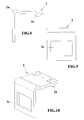
Figure 8 is a side view of the top bracket; -
Figure 9 is a perspective view of said top bracket; -
Figure 10 is a further perspective view of said top bracket: -
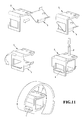
Figure 11 shows a sequence of operations for clamping or locking a spring to a framework of an agricultural machine by the locking construction according to the present invention; -
Figure 12 shows a diagram illustrating the evolvement of forces operating in the subject construction in comparison with a conventional attachment or clamping system; and -
Figures 13 and 14 show the forces operating on same elements of the inventive construction. - With reference to the number references of the above mentioned figures, the locking construction according to the present invention, which has been generally indicated by the
reference number 10, comprises atop bracket 2, to be clamped to aframework 5 of an agricultural machine, not shown in the figures, and acounter-bracket 1 cooperating with the top bracket to lock a furtherfunctional operating element 4 to saidmachine framework 5. - The construction further comprises a clamping or locking device consisting of a clamping or locking
bolt 3 engaging thecounter-bracket 1 andtop bracket 2 to lock the functional or operatingelement 4 on theframework 5. - Said functional or
operating element 4 comprises, for example, a spring or a resilient tooth element for processing soil either directly or through a disc or plow element. - The
top bracket 2,counter-bracket 1 and clampingbolt 3 clamp or lock thespring 4 on theframework 5, and provide five operating effects, occurring as the component pieces are clamped to one another by said clampingbolt 3. - The first locking effect is provided in a vertical direction, on the front of the
framework 5, through the clampingbolt 3 tightly coupling the components to one another. - This first locking effect is indicated by the reference arrow E1 in
Figure 13 . - The second locking effect is provided in a vertical direction, on the rear of the
framework 5, where thetop bracket 2 has a special concavecurved shape 2a which, through a resilient deformation of the framework material, provides a "clamping" action. - This second locking effect is indicated by the reference arrow E2 in
Figure 13 . - The third locking effect is provided in a horizontal direction on the top of the framework, where the
top bracket 2 has a bossed configuration, including a plurality of backward offset "bosses" 2b, arranged with respect to the framework at a shorter distance than prior brackets. - Said bosses operate on a framework edge to draw or pull the
bracket 2 against the framework, to cause said bracket to tightly contact said framework. - This third locking effect is indicated by the reference arrow E3 in
Figure 13 . - The fourth locking effect is directed in a horizontal direction, on the bottom of the framework, where the
counter-bracket 1 comprises two tongues or fins engaged against the front part of the framework for frontward drawing thecounter-bracket 1 as theclamping bolt 3 is locked. - Said
counter-bracket 1 comprises a plurality oftooth elements 1c meshing with or engaging therear face 2c of thetop bracket 2. - Thus, the
counter-bracket 1 will draw or pull thetop bracket 2 against theframework 5. - This fourth effect is indicated by the reference arrow E4 in
Figure 13 . - The fifth locking effect is achieved in a turning or rotary direction.
- The
counter-bracket 1, engaged between thetop bracket 2 andframework 5, comprisesbent edge portions 1 b locking the side portions of thespring 4 thereby preventing any rotary movement of the spring and framework. - Thus, the spring is prevented from being laterally offset and turning under the framework.
- This fifth locking effect has been indicated by the reference arrow E5 in
Figure 14 . - For assembling the construction, the
top bracket 2 comprises awindow 2e having such a height allowing thecounter-bracket 1 to be diagonally engaged, as schematically shown inFigure 11 . - Thus, after having engaged the
counter-bracket 1, the latter is so turned to prevent thetooth elements 1 c from disengaging from the top bracket while engaging against thesurface 2c. - The
counter-bracket 1 comprises a slot 1e facilitating a screw insertion in the assembling operation and allowing thebracket 2 to be approached as theclamping bolt 3 is locked. - Thus, as the clamping bolt is clamped or locked, the tongues 1a will slide on the edge of the
framework 5, frontward drawing thecounter-bracket 1 and causing thetooth elements 1c to approach thesurface 2c of thetop bracket 2, thereby locking all the mentioned components. - The locking construction according to the present invention may be in particular, though not exclusively, used in all cases in which the springs provide pushing forces crosswise to the agricultural machine feeding in driving direction, which forces would tend to laterally offset and/or turn the springs of a trawl or disc type.
- As clearly shown in the diagram of
Figure 12 , with the side force applied to the spring being the same, the inventive locking construction will reduce a side offset, at the tip of the spring, of about five times that of a prior simple-bracket locking system. - It has been found that the invention fully achieves the intended aim and objects.
- In practicing the invention, the used materials, as well as the contingent size and shapes can be any, according to requirements.
Claims (10)
- A locking construction for agricultural machines, characterized in that said locking construction comprises a top bracket to be clamped to an agricultural machine framework, and a counter-bracket cooperating with said top bracket to lock a functional element to said framework, said construction comprising moreover a clamping or locking device, engaging said counter-bracket and top bracket to lock said functional element on said framework.
- A locking construction, according to claim 1, characterized in that said clamping device consists of a clamping bolt.
- A locking construction, according to claim 1, characterized in that said functional element consists of a spring or resilient tooth element, operating for processing soil either directly or through a disc element.
- A locking construction, according to claim 1, characterized in that said top bracket has a concave arched shape allowing said top bracket to be resiliently deformed.
- A locking construction, according to claim 4, characterized in that said top bracket comprises backward offset boss elements, arranged near the framework, operating on a framework edge to draw said bracket against said framework and causing said bracket to tightly contact said framework.
- A locking construction, according to one or more of the preceding claims, characterized in that said counter-bracket comprises two tongues engaged against a front portion of said framework and frontward drawing said counter-bracket, as said clamping bolt is clamped.
- A locking construction, according to one or more of the preceding claims, characterized in that said counter-bracket comprises a tooth element pattern engageable against a rear face of the top bracket.
- A locking construction, according to one or more of the preceding claims, characterized in that said counter-bracket comprises counter-bracket edges so bent as to lock side portions of said spring thereby preventing said spring and framework from mutually turning.
- A locking construction, according to one or more of the preceding claims, characterized in that said top bracket comprises a window for receiving said counter-bracket, said counter-bracket comprising a slot facilitating an insertion of said clamping bolt in an assembling operation and allowing said top bracket to approach as said clamping bolt is clamped.
- A locking construction, according to one or more of the preceding claims, characterized in that said top bracket, counter-bracket and clamping bolt lock the functional element on the framework by operating according to five operating effects occurring as the component pieces are clamped to one another by said clamping bolt; a first locking effect occurring in a vertical direction, on a front of the framework, through said clamping bolt tightly clamping the components; a second locking effect occurring in a vertical direction, on a rear of the framework, where the top bracket has a concave arch shape providing clamping by a resilient deformation of its material; a third locking effect occurring in a horizontal direction, on the top of the framework, where said top bracket has a boss pattern with a plurality of bosses operating on the framework edge to draw the bracket against said framework to tightly contact said framework; a fourth locking effect occurring in a horizontal direction, on the bottom of the framework, where said counter-bracket comprises two tongues engaged against a front portion of the framework and, as the clamping bolt is clamped, frontward drawing said counter-bracket; the tooth elements of the counter-bracket engaging against a rear face of the top bracket, thereby, as the counter-bracket is drawn, the top bracket is abutted against the framework; a fifth effect occurring in a rotary direction; said counter-bracket, engaging between the top bracket and framework, including bent counter-bracket edges to lock side portions of said spring and prevent any rotary movement of the spring and framework while hindering a side offset of the spring and a rotation of said spring under the framework.
Applications Claiming Priority (1)
| Application Number | Priority Date | Filing Date | Title |
|---|---|---|---|
| ITMI20140497 | 2014-03-24 |
Publications (2)
| Publication Number | Publication Date |
|---|---|
| EP2923538A1 true EP2923538A1 (en) | 2015-09-30 |
| EP2923538B1 EP2923538B1 (en) | 2020-09-30 |
Family
ID=50943403
Family Applications (1)
| Application Number | Title | Priority Date | Filing Date |
|---|---|---|---|
| EP14200008.2A Active EP2923538B1 (en) | 2014-03-24 | 2014-12-23 | Locking construction for agricultural machines |
Country Status (2)
| Country | Link |
|---|---|
| EP (1) | EP2923538B1 (en) |
| ES (1) | ES2829595T3 (en) |
Cited By (3)
| Publication number | Priority date | Publication date | Assignee | Title |
|---|---|---|---|---|
| EP3245855A1 (en) * | 2016-04-28 | 2017-11-22 | Horsch Maschinen GmbH | Agricultural soil working implement, spring tine for same and assembly of a spring tine |
| DE102016111773A1 (en) | 2016-06-28 | 2017-12-28 | Horsch Maschinen Gmbh | Agricultural tillage implement with tillage tools and mounting arrangement for a tillage tool |
| WO2019235996A1 (en) * | 2018-06-08 | 2019-12-12 | Väderstad Holding Ab | Fastening device and method for releasable fixing of soil working tools to an agricultural implement |
Citations (4)
| Publication number | Priority date | Publication date | Assignee | Title |
|---|---|---|---|---|
| US3425755A (en) * | 1966-03-22 | 1969-02-04 | Robert L Harris | Spring shank clamp |
| US4047823A (en) * | 1976-09-07 | 1977-09-13 | Allis-Chalmers Corporation | Clamping arrangement for a flexible earth-working tine |
| WO2006028392A1 (en) * | 2004-09-09 | 2006-03-16 | Tomorrow's Innovations Limited | Improved coulter and coulter mounting |
| DE102012005027A1 (en) * | 2012-03-12 | 2013-09-12 | Köckerling GmbH & Co. KG | Soil tilling machine e.g. coulter cultivator mounted on agricultural machine, has intermediate element that is arranged between other end region of S-shaped resilient spring tine and support frame element |
-
2014
- 2014-12-23 ES ES14200008T patent/ES2829595T3/en active Active
- 2014-12-23 EP EP14200008.2A patent/EP2923538B1/en active Active
Patent Citations (4)
| Publication number | Priority date | Publication date | Assignee | Title |
|---|---|---|---|---|
| US3425755A (en) * | 1966-03-22 | 1969-02-04 | Robert L Harris | Spring shank clamp |
| US4047823A (en) * | 1976-09-07 | 1977-09-13 | Allis-Chalmers Corporation | Clamping arrangement for a flexible earth-working tine |
| WO2006028392A1 (en) * | 2004-09-09 | 2006-03-16 | Tomorrow's Innovations Limited | Improved coulter and coulter mounting |
| DE102012005027A1 (en) * | 2012-03-12 | 2013-09-12 | Köckerling GmbH & Co. KG | Soil tilling machine e.g. coulter cultivator mounted on agricultural machine, has intermediate element that is arranged between other end region of S-shaped resilient spring tine and support frame element |
Cited By (4)
| Publication number | Priority date | Publication date | Assignee | Title |
|---|---|---|---|---|
| EP3245855A1 (en) * | 2016-04-28 | 2017-11-22 | Horsch Maschinen GmbH | Agricultural soil working implement, spring tine for same and assembly of a spring tine |
| DE102016111773A1 (en) | 2016-06-28 | 2017-12-28 | Horsch Maschinen Gmbh | Agricultural tillage implement with tillage tools and mounting arrangement for a tillage tool |
| DE102016111773B4 (en) | 2016-06-28 | 2024-05-08 | Horsch Maschinen Gmbh | Agricultural soil tillage implement with soil tillage tools and fastening arrangement for a soil tillage tool |
| WO2019235996A1 (en) * | 2018-06-08 | 2019-12-12 | Väderstad Holding Ab | Fastening device and method for releasable fixing of soil working tools to an agricultural implement |
Also Published As
| Publication number | Publication date |
|---|---|
| ES2829595T3 (en) | 2021-06-01 |
| ES2829595T8 (en) | 2022-03-18 |
| EP2923538B1 (en) | 2020-09-30 |
Similar Documents
| Publication | Publication Date | Title |
|---|---|---|
| USD1090715S1 (en) | Curved button panel display for an electronic gaming machine | |
| USD857762S1 (en) | Lip shroud for a ground engaging machine implement | |
| USD822363S1 (en) | Shoe upper | |
| JP6599180B2 (en) | U-based fastener with improved rib attachment | |
| EP2923538B1 (en) | Locking construction for agricultural machines | |
| USD874253S1 (en) | Racheting post for an electronic device protective case | |
| USD944461S1 (en) | Mandible shield | |
| USD861464S1 (en) | Bearing plate | |
| USD891811S1 (en) | Waste cassette | |
| DE202009012400U1 (en) | Safe pacifier clip | |
| EP2622981B9 (en) | An eye fastener | |
| USD920710S1 (en) | Waste cassette | |
| JP2013508044A5 (en) | ||
| US2182523A (en) | Structure element and connector | |
| USD860124S1 (en) | Center console for automobile | |
| EP3405063B1 (en) | A fastening device and a fastening system | |
| US2138823A (en) | Flexible arch support | |
| JP2017112003A5 (en) | ||
| USD860122S1 (en) | Center console for automobile | |
| USD860121S1 (en) | Center console for automobile | |
| EP3116295B1 (en) | Locking device for a wear part of a soil-working implement | |
| USD867180S1 (en) | Ruler | |
| EP3035354B1 (en) | Fastening system with easy removal for electrical and / or electronic devices | |
| USD1105310S1 (en) | Sprocket retention system for exercise device | |
| US1800798A (en) | Bird-cage fastener |
Legal Events
| Date | Code | Title | Description |
|---|---|---|---|
| PUAI | Public reference made under article 153(3) epc to a published international application that has entered the european phase |
Free format text: ORIGINAL CODE: 0009012 |
|
| AK | Designated contracting states |
Kind code of ref document: A1 Designated state(s): AL AT BE BG CH CY CZ DE DK EE ES FI FR GB GR HR HU IE IS IT LI LT LU LV MC MK MT NL NO PL PT RO RS SE SI SK SM TR |
|
| AX | Request for extension of the european patent |
Extension state: BA ME |
|
| 17P | Request for examination filed |
Effective date: 20160329 |
|
| STAA | Information on the status of an ep patent application or granted ep patent |
Free format text: STATUS: EXAMINATION IS IN PROGRESS |
|
| 17Q | First examination report despatched |
Effective date: 20180410 |
|
| GRAP | Despatch of communication of intention to grant a patent |
Free format text: ORIGINAL CODE: EPIDOSNIGR1 |
|
| STAA | Information on the status of an ep patent application or granted ep patent |
Free format text: STATUS: GRANT OF PATENT IS INTENDED |
|
| INTG | Intention to grant announced |
Effective date: 20191115 |
|
| RIN1 | Information on inventor provided before grant (corrected) |
Inventor name: BIANCHI, SANDRO |
|
| GRAS | Grant fee paid |
Free format text: ORIGINAL CODE: EPIDOSNIGR3 |
|
| GRAA | (expected) grant |
Free format text: ORIGINAL CODE: 0009210 |
|
| STAA | Information on the status of an ep patent application or granted ep patent |
Free format text: STATUS: THE PATENT HAS BEEN GRANTED |
|
| AK | Designated contracting states |
Kind code of ref document: B1 Designated state(s): AL AT BE BG CH CY CZ DE DK EE ES FI FR GB GR HR HU IE IS IT LI LT LU LV MC MK MT NL NO PL PT RO RS SE SI SK SM TR |
|
| REG | Reference to a national code |
Ref country code: CH Ref legal event code: EP |
|
| REG | Reference to a national code |
Ref country code: DE Ref legal event code: R096 Ref document number: 602014063738 Country of ref document: DE |
|
| REG | Reference to a national code |
Ref country code: IE Ref legal event code: FG4D |
|
| REG | Reference to a national code |
Ref country code: AT Ref legal event code: REF Ref document number: 1256187 Country of ref document: AT Kind code of ref document: T Effective date: 20200515 |
|
| PUAC | Information related to the publication of a b1 document modified or deleted |
Free format text: ORIGINAL CODE: 0009299EPPU |
|
| STAA | Information on the status of an ep patent application or granted ep patent |
Free format text: STATUS: GRANT OF PATENT IS INTENDED |
|
| REG | Reference to a national code |
Ref country code: CH Ref legal event code: PK Free format text: DIE ERTEILUNG WURDE VOM EPA WIDERRUFEN. |
|
| DB1 | Publication of patent cancelled |
Effective date: 20200612 |
|
| REG | Reference to a national code |
Ref country code: DE Ref legal event code: R107 Ref document number: 602014063738 Country of ref document: DE |
|
| REG | Reference to a national code |
Ref country code: LU Ref legal event code: HK Effective date: 20200708 |
|
| GRAA | (expected) grant |
Free format text: ORIGINAL CODE: 0009210 |
|
| STAA | Information on the status of an ep patent application or granted ep patent |
Free format text: STATUS: THE PATENT HAS BEEN GRANTED |
|
| REG | Reference to a national code |
Ref country code: AT Ref legal event code: REZ Ref document number: 1256187 Country of ref document: AT Kind code of ref document: T Effective date: 20200415 |
|
| AK | Designated contracting states |
Kind code of ref document: B1 Designated state(s): AL AT BE BG CH CY CZ DE DK EE ES FI FR GB GR HR HU IE IS IT LI LT LU LV MC MK MT NL NO PL PT RO RS SE SI SK SM TR |
|
| REG | Reference to a national code |
Ref country code: CH Ref legal event code: EP |
|
| REG | Reference to a national code |
Ref country code: AT Ref legal event code: REF Ref document number: 1256187 Country of ref document: AT Kind code of ref document: T Effective date: 20201015 Ref country code: DE Ref legal event code: R096 Ref document number: 602014063738 Country of ref document: DE Ref country code: CH Ref legal event code: PK Free format text: DIE ERTEILUNG VOM 15.04.2020 WURDE VOM EPA WIDERRUFEN. |
|
| PG25 | Lapsed in a contracting state [announced via postgrant information from national office to epo] |
Ref country code: RS Free format text: LAPSE BECAUSE OF FAILURE TO SUBMIT A TRANSLATION OF THE DESCRIPTION OR TO PAY THE FEE WITHIN THE PRESCRIBED TIME-LIMIT Effective date: 20200930 |
|
| PG25 | Lapsed in a contracting state [announced via postgrant information from national office to epo] |
Ref country code: AL Free format text: LAPSE BECAUSE OF FAILURE TO SUBMIT A TRANSLATION OF THE DESCRIPTION OR TO PAY THE FEE WITHIN THE PRESCRIBED TIME-LIMIT Effective date: 20200930 |
|
| PG25 | Lapsed in a contracting state [announced via postgrant information from national office to epo] |
Ref country code: HR Free format text: LAPSE BECAUSE OF FAILURE TO SUBMIT A TRANSLATION OF THE DESCRIPTION OR TO PAY THE FEE WITHIN THE PRESCRIBED TIME-LIMIT Effective date: 20200930 Ref country code: BG Free format text: LAPSE BECAUSE OF FAILURE TO SUBMIT A TRANSLATION OF THE DESCRIPTION OR TO PAY THE FEE WITHIN THE PRESCRIBED TIME-LIMIT Effective date: 20201230 Ref country code: NO Free format text: LAPSE BECAUSE OF FAILURE TO SUBMIT A TRANSLATION OF THE DESCRIPTION OR TO PAY THE FEE WITHIN THE PRESCRIBED TIME-LIMIT Effective date: 20201230 Ref country code: FI Free format text: LAPSE BECAUSE OF FAILURE TO SUBMIT A TRANSLATION OF THE DESCRIPTION OR TO PAY THE FEE WITHIN THE PRESCRIBED TIME-LIMIT Effective date: 20200930 |
|
| REG | Reference to a national code |
Ref country code: AT Ref legal event code: MK05 Ref document number: 1256187 Country of ref document: AT Kind code of ref document: T Effective date: 20200930 |
|
| PG25 | Lapsed in a contracting state [announced via postgrant information from national office to epo] |
Ref country code: LV Free format text: LAPSE BECAUSE OF FAILURE TO SUBMIT A TRANSLATION OF THE DESCRIPTION OR TO PAY THE FEE WITHIN THE PRESCRIBED TIME-LIMIT Effective date: 20200930 |
|
| REG | Reference to a national code |
Ref country code: NL Ref legal event code: MP Effective date: 20200930 |
|
| REG | Reference to a national code |
Ref country code: LT Ref legal event code: MG4D |
|
| PG25 | Lapsed in a contracting state [announced via postgrant information from national office to epo] |
Ref country code: SM Free format text: LAPSE BECAUSE OF FAILURE TO SUBMIT A TRANSLATION OF THE DESCRIPTION OR TO PAY THE FEE WITHIN THE PRESCRIBED TIME-LIMIT Effective date: 20200930 Ref country code: RO Free format text: LAPSE BECAUSE OF FAILURE TO SUBMIT A TRANSLATION OF THE DESCRIPTION OR TO PAY THE FEE WITHIN THE PRESCRIBED TIME-LIMIT Effective date: 20200930 Ref country code: PT Free format text: LAPSE BECAUSE OF FAILURE TO SUBMIT A TRANSLATION OF THE DESCRIPTION OR TO PAY THE FEE WITHIN THE PRESCRIBED TIME-LIMIT Effective date: 20210201 Ref country code: NL Free format text: LAPSE BECAUSE OF FAILURE TO SUBMIT A TRANSLATION OF THE DESCRIPTION OR TO PAY THE FEE WITHIN THE PRESCRIBED TIME-LIMIT Effective date: 20200930 Ref country code: LT Free format text: LAPSE BECAUSE OF FAILURE TO SUBMIT A TRANSLATION OF THE DESCRIPTION OR TO PAY THE FEE WITHIN THE PRESCRIBED TIME-LIMIT Effective date: 20200930 Ref country code: EE Free format text: LAPSE BECAUSE OF FAILURE TO SUBMIT A TRANSLATION OF THE DESCRIPTION OR TO PAY THE FEE WITHIN THE PRESCRIBED TIME-LIMIT Effective date: 20200930 Ref country code: CZ Free format text: LAPSE BECAUSE OF FAILURE TO SUBMIT A TRANSLATION OF THE DESCRIPTION OR TO PAY THE FEE WITHIN THE PRESCRIBED TIME-LIMIT Effective date: 20200930 |
|
| PG25 | Lapsed in a contracting state [announced via postgrant information from national office to epo] |
Ref country code: AT Free format text: LAPSE BECAUSE OF FAILURE TO SUBMIT A TRANSLATION OF THE DESCRIPTION OR TO PAY THE FEE WITHIN THE PRESCRIBED TIME-LIMIT Effective date: 20200930 |
|
| REG | Reference to a national code |
Ref country code: ES Ref legal event code: FG2A Ref document number: 2829595 Country of ref document: ES Kind code of ref document: T3 Effective date: 20210601 |
|
| PG25 | Lapsed in a contracting state [announced via postgrant information from national office to epo] |
Ref country code: SK Free format text: LAPSE BECAUSE OF FAILURE TO SUBMIT A TRANSLATION OF THE DESCRIPTION OR TO PAY THE FEE WITHIN THE PRESCRIBED TIME-LIMIT Effective date: 20200930 |
|
| REG | Reference to a national code |
Ref country code: DE Ref legal event code: R097 Ref document number: 602014063738 Country of ref document: DE |
|
| REG | Reference to a national code |
Ref country code: CH Ref legal event code: PL |
|
| PLBE | No opposition filed within time limit |
Free format text: ORIGINAL CODE: 0009261 |
|
| STAA | Information on the status of an ep patent application or granted ep patent |
Free format text: STATUS: NO OPPOSITION FILED WITHIN TIME LIMIT |
|
| GBPC | Gb: european patent ceased through non-payment of renewal fee |
Effective date: 20201223 |
|
| PG25 | Lapsed in a contracting state [announced via postgrant information from national office to epo] |
Ref country code: DK Free format text: LAPSE BECAUSE OF FAILURE TO SUBMIT A TRANSLATION OF THE DESCRIPTION OR TO PAY THE FEE WITHIN THE PRESCRIBED TIME-LIMIT Effective date: 20200930 Ref country code: MC Free format text: LAPSE BECAUSE OF FAILURE TO SUBMIT A TRANSLATION OF THE DESCRIPTION OR TO PAY THE FEE WITHIN THE PRESCRIBED TIME-LIMIT Effective date: 20200930 |
|
| REG | Reference to a national code |
Ref country code: BE Ref legal event code: MM Effective date: 20201231 |
|
| 26N | No opposition filed |
Effective date: 20210701 |
|
| PG25 | Lapsed in a contracting state [announced via postgrant information from national office to epo] |
Ref country code: IE Free format text: LAPSE BECAUSE OF NON-PAYMENT OF DUE FEES Effective date: 20201223 Ref country code: LU Free format text: LAPSE BECAUSE OF NON-PAYMENT OF DUE FEES Effective date: 20201223 |
|
| PG25 | Lapsed in a contracting state [announced via postgrant information from national office to epo] |
Ref country code: LI Free format text: LAPSE BECAUSE OF NON-PAYMENT OF DUE FEES Effective date: 20201231 Ref country code: GB Free format text: LAPSE BECAUSE OF NON-PAYMENT OF DUE FEES Effective date: 20201223 Ref country code: CH Free format text: LAPSE BECAUSE OF NON-PAYMENT OF DUE FEES Effective date: 20201231 Ref country code: SI Free format text: LAPSE BECAUSE OF FAILURE TO SUBMIT A TRANSLATION OF THE DESCRIPTION OR TO PAY THE FEE WITHIN THE PRESCRIBED TIME-LIMIT Effective date: 20200930 |
|
| PG25 | Lapsed in a contracting state [announced via postgrant information from national office to epo] |
Ref country code: IS Free format text: LAPSE BECAUSE OF FAILURE TO SUBMIT A TRANSLATION OF THE DESCRIPTION OR TO PAY THE FEE WITHIN THE PRESCRIBED TIME-LIMIT Effective date: 20210130 Ref country code: TR Free format text: LAPSE BECAUSE OF FAILURE TO SUBMIT A TRANSLATION OF THE DESCRIPTION OR TO PAY THE FEE WITHIN THE PRESCRIBED TIME-LIMIT Effective date: 20200930 Ref country code: MT Free format text: LAPSE BECAUSE OF FAILURE TO SUBMIT A TRANSLATION OF THE DESCRIPTION OR TO PAY THE FEE WITHIN THE PRESCRIBED TIME-LIMIT Effective date: 20200930 Ref country code: CY Free format text: LAPSE BECAUSE OF FAILURE TO SUBMIT A TRANSLATION OF THE DESCRIPTION OR TO PAY THE FEE WITHIN THE PRESCRIBED TIME-LIMIT Effective date: 20200930 |
|
| PG25 | Lapsed in a contracting state [announced via postgrant information from national office to epo] |
Ref country code: SE Free format text: LAPSE BECAUSE OF FAILURE TO SUBMIT A TRANSLATION OF THE DESCRIPTION OR TO PAY THE FEE WITHIN THE PRESCRIBED TIME-LIMIT Effective date: 20200930 Ref country code: MK Free format text: LAPSE BECAUSE OF FAILURE TO SUBMIT A TRANSLATION OF THE DESCRIPTION OR TO PAY THE FEE WITHIN THE PRESCRIBED TIME-LIMIT Effective date: 20200930 |
|
| PG25 | Lapsed in a contracting state [announced via postgrant information from national office to epo] |
Ref country code: BE Free format text: LAPSE BECAUSE OF NON-PAYMENT OF DUE FEES Effective date: 20201231 |
|
| PG25 | Lapsed in a contracting state [announced via postgrant information from national office to epo] |
Ref country code: GR Free format text: LAPSE BECAUSE OF FAILURE TO SUBMIT A TRANSLATION OF THE DESCRIPTION OR TO PAY THE FEE WITHIN THE PRESCRIBED TIME-LIMIT Effective date: 20200930 |
|
| P01 | Opt-out of the competence of the unified patent court (upc) registered |
Effective date: 20230714 |
|
| PG25 | Lapsed in a contracting state [announced via postgrant information from national office to epo] |
Ref country code: PL Free format text: LAPSE BECAUSE OF FAILURE TO SUBMIT A TRANSLATION OF THE DESCRIPTION OR TO PAY THE FEE WITHIN THE PRESCRIBED TIME-LIMIT Effective date: 20200930 |
|
| PGFP | Annual fee paid to national office [announced via postgrant information from national office to epo] |
Ref country code: IT Payment date: 20231116 Year of fee payment: 10 Ref country code: FR Payment date: 20231227 Year of fee payment: 10 |
|
| PGFP | Annual fee paid to national office [announced via postgrant information from national office to epo] |
Ref country code: ES Payment date: 20240102 Year of fee payment: 10 |
|
| PGFP | Annual fee paid to national office [announced via postgrant information from national office to epo] |
Ref country code: DE Payment date: 20231229 Year of fee payment: 10 |
|
| REG | Reference to a national code |
Ref country code: DE Ref legal event code: R119 Ref document number: 602014063738 Country of ref document: DE |
|
| PG25 | Lapsed in a contracting state [announced via postgrant information from national office to epo] |
Ref country code: DE Free format text: LAPSE BECAUSE OF NON-PAYMENT OF DUE FEES Effective date: 20250701 |
|
| PG25 | Lapsed in a contracting state [announced via postgrant information from national office to epo] |
Ref country code: IT Free format text: LAPSE BECAUSE OF NON-PAYMENT OF DUE FEES Effective date: 20241223 |
|
| PG25 | Lapsed in a contracting state [announced via postgrant information from national office to epo] |
Ref country code: FR Free format text: LAPSE BECAUSE OF NON-PAYMENT OF DUE FEES Effective date: 20241231 |
|
| REG | Reference to a national code |
Ref country code: ES Ref legal event code: FD2A Effective date: 20260206 |
|
| PG25 | Lapsed in a contracting state [announced via postgrant information from national office to epo] |
Ref country code: ES Free format text: LAPSE BECAUSE OF NON-PAYMENT OF DUE FEES Effective date: 20241224 |