EP2922768B1 - Container having a use-evident device - Google Patents
Container having a use-evident device Download PDFInfo
- Publication number
- EP2922768B1 EP2922768B1 EP13786053.2A EP13786053A EP2922768B1 EP 2922768 B1 EP2922768 B1 EP 2922768B1 EP 13786053 A EP13786053 A EP 13786053A EP 2922768 B1 EP2922768 B1 EP 2922768B1
- Authority
- EP
- European Patent Office
- Prior art keywords
- container
- package
- display
- indicator
- closure
- Prior art date
- Legal status (The legal status is an assumption and is not a legal conclusion. Google has not performed a legal analysis and makes no representation as to the accuracy of the status listed.)
- Not-in-force
Links
Images


Classifications
-
- B—PERFORMING OPERATIONS; TRANSPORTING
- B65—CONVEYING; PACKING; STORING; HANDLING THIN OR FILAMENTARY MATERIAL
- B65D—CONTAINERS FOR STORAGE OR TRANSPORT OF ARTICLES OR MATERIALS, e.g. BAGS, BARRELS, BOTTLES, BOXES, CANS, CARTONS, CRATES, DRUMS, JARS, TANKS, HOPPERS, FORWARDING CONTAINERS; ACCESSORIES, CLOSURES, OR FITTINGS THEREFOR; PACKAGING ELEMENTS; PACKAGES
- B65D55/00—Accessories for container closures not otherwise provided for
- B65D55/02—Locking devices; Means for discouraging or indicating unauthorised opening or removal of closure
- B65D55/026—Locking devices; Means for discouraging or indicating unauthorised opening or removal of closure initial opening or unauthorised access being indicated by a visual change using indicators other than tearable means, e.g. change of colour, pattern or opacity
-
- B—PERFORMING OPERATIONS; TRANSPORTING
- B65—CONVEYING; PACKING; STORING; HANDLING THIN OR FILAMENTARY MATERIAL
- B65D—CONTAINERS FOR STORAGE OR TRANSPORT OF ARTICLES OR MATERIALS, e.g. BAGS, BARRELS, BOTTLES, BOXES, CANS, CARTONS, CRATES, DRUMS, JARS, TANKS, HOPPERS, FORWARDING CONTAINERS; ACCESSORIES, CLOSURES, OR FITTINGS THEREFOR; PACKAGING ELEMENTS; PACKAGES
- B65D79/00—Kinds or details of packages, not otherwise provided for
-
- B—PERFORMING OPERATIONS; TRANSPORTING
- B65—CONVEYING; PACKING; STORING; HANDLING THIN OR FILAMENTARY MATERIAL
- B65B—MACHINES, APPARATUS OR DEVICES FOR, OR METHODS OF, PACKAGING ARTICLES OR MATERIALS; UNPACKING
- B65B3/00—Packaging plastic material, semiliquids, liquids or mixed solids and liquids, in individual containers or receptacles, e.g. bags, sacks, boxes, cartons, cans, or jars
- B65B3/04—Methods of, or means for, filling the material into the containers or receptacles
-
- B—PERFORMING OPERATIONS; TRANSPORTING
- B65—CONVEYING; PACKING; STORING; HANDLING THIN OR FILAMENTARY MATERIAL
- B65B—MACHINES, APPARATUS OR DEVICES FOR, OR METHODS OF, PACKAGING ARTICLES OR MATERIALS; UNPACKING
- B65B69/00—Unpacking of articles or materials, not otherwise provided for
-
- B—PERFORMING OPERATIONS; TRANSPORTING
- B65—CONVEYING; PACKING; STORING; HANDLING THIN OR FILAMENTARY MATERIAL
- B65D—CONTAINERS FOR STORAGE OR TRANSPORT OF ARTICLES OR MATERIALS, e.g. BAGS, BARRELS, BOTTLES, BOXES, CANS, CARTONS, CRATES, DRUMS, JARS, TANKS, HOPPERS, FORWARDING CONTAINERS; ACCESSORIES, CLOSURES, OR FITTINGS THEREFOR; PACKAGING ELEMENTS; PACKAGES
- B65D2203/00—Decoration means, markings, information elements, contents indicators
- B65D2203/10—Transponders
-
- B—PERFORMING OPERATIONS; TRANSPORTING
- B65—CONVEYING; PACKING; STORING; HANDLING THIN OR FILAMENTARY MATERIAL
- B65D—CONTAINERS FOR STORAGE OR TRANSPORT OF ARTICLES OR MATERIALS, e.g. BAGS, BARRELS, BOTTLES, BOXES, CANS, CARTONS, CRATES, DRUMS, JARS, TANKS, HOPPERS, FORWARDING CONTAINERS; ACCESSORIES, CLOSURES, OR FITTINGS THEREFOR; PACKAGING ELEMENTS; PACKAGES
- B65D2203/00—Decoration means, markings, information elements, contents indicators
- B65D2203/12—Audible, olfactory or visual signalling means
Definitions
- the present invention is directed to a package and, more particularly, to a package having anti-counterfeit and/or tamper-evident features.
- a beverage container can include a fitment that renders the container non-refillable, so as to impede efforts to refill the container with inferior products.
- U.S. Patent 3,399,811 illustrates a container of this type.
- International Patent Application WO 2011/092461 A2 shows an elapsed time indicator with an activator arrangement having a fluid reservoir and a conduit configured to provide a predetermined flow rate of fluid along the conduit. It comprises further a visual display arrangement configured to change appearance on exposure to the fluid.
- the activator arrangement can response to an activation event to permit the fluid to flow.
- FIG. 2004/110892 A1 shows a container, comprising means of producing an output such as a light signal when the container is opened. Opening the container causes switching of a detector circuit included in the container, which in turn causes production of the output signal. Removing a cap of the container may directly close or open a switch within a detector circuit. The switch may also be activated by a change in pressure within the container or by temperature.
- a general object of the present disclosure is to provide a product including a container and a use indicator carried by the container that indicates whether the container has been used and, thus, will provide evidence of efforts to repackage the container with counterfeit product.
- a package as defined in claim 1 is provided.
- a product that includes a container, and an indicator carried by the container, and responsive to a change in at least one state of the container to irreversibly modify a visual characteristic visible from outside the container.
- a method of producing a package that includes (a) coupling at least a portion of an indicator to a container, wherein the indicator includes a sensor and a display; (b) filling the container with an original flowable product; and (c) closing the container with a closure. After at least one of the filling or closing steps, the display exhibits an initial state of a visual characteristic of a plurality of states of the visual characteristic.
- FIG. 1 illustrates a package 10 in accordance with an illustrative embodiment of the disclosure useful for understanding the invention as including a container 12, a closure 13 for the container 12, an authentic or original material or product P filling the container 12, and an indicator 14 carried by the container 12.
- the indicator 14 may facilitate evidencing of efforts to tamper with the package 10, by being responsive to a change in a state of the container 12 to irreversibly change or modify an optical or visual characteristic visible from outside the container 12.
- the change in state of the container 12 may include opening of the container 12 and/or dispensing of product out of the container 12.
- the indicator 14 may provide a counterfeit deterrence feature that provides evidence that an original package has been used. More specifically, the indicator 14 may indicate design-intent use of the container 12, like container opening and/or product dispensing, such that a purchaser can see that the container 12 has been "used” after the container 12 was originally packaged with the product P carried therein and the closure 13 coupled thereto. For example, the package 10 may be sealed by a beverage manufacturer, delivered to a customer, opened, and then partially or completely emptied of its original flowable product P.
- the refilled and repackaged package 10 will include the state modified indicator 14 as evidence that the package 10 is not original and, instead, has been refilled and repackaged.
- the container 12 or package 10 are permanently or irreversibly tagged as being a once-fillable container or package.
- purchasers will become educated to spot refilled counterfeit packages.
- counterfeiters will be deterred from offering counterfeit packages to such educated purchasers.
- the container 12 may be of one-piece integrally formed construction, for example, metal, glass, ceramic, or plastic construction.
- integrally formed construction does not exclude one-piece integrally molded layered glass constructions of the type disclosed for example in U.S. Patent 4,740,401 , or one-piece glass bottles to which other structure is added after the bottle-forming operation.
- the container 12 may be fabricated in press-and-blow or blow-and-blow glass container manufacturing operations, or in a plastic injection and/or blow molding operation, or in any other suitable manner.
- the container 12 may be of any suitable shape, and may include a jug, jar, bottle, other food or beverage container, or any other suitable container.
- the container 12 may include a base 15 on which the container 12 may be supported, a body 16 extending axially from the base 15, a shoulder 18 extending radially and axially from the body 16, and a neck 20 extending axially from the shoulder 18.
- the term axial includes oriented generally along a longitudinal axis of the closure, container, or package and may include but is not limited to a direction that is strictly parallel to a container longitudinal central axis A.
- the body 16 and the neck 20 may be generally cylindrical, as illustrated, or they may be tapered or of any other suitable shape.
- the neck 20 may include a lip or axial outward end surface 22, and an interior surface 26.
- the neck 20 also may include a finish, which may include a capping flange 28, and one or more threads or thread segments 30, or the like for coupling to the closure 13 ( FIG. 1 ).
- the product P may be dispensably disposed within the container 12 of the package 10.
- a product manufacturer may fill the container 12 with the authentic or original flowable product P at a packaging plant and close the container 12 with the closure 13, which may be fastened to the neck 20 of the container 12 in any suitable manner and may be sealed thereto with wax, paper or plastic seal, or any other suitable seal (none shown). Thereafter, the closure 13 may be removed and the product P dispensed out of the container 12 through the neck 20.
- the closure 13 may include a cap, cork, plug, or any other suitable type of closure.
- the product P may include a liquid or solid, for example, a beverage, for instance, beer, wine, liquor, soda, or any other suitable beverage or liquid, or a food of any kind.
- the indicator 14 may include any suitable components and may be carried in any suitable location(s) of the container 12, internally and/or externally of the container 12. One or more portions of the indicator 14 may be non-removably secured to the container 12, or carried by the container 12 in any other suitable manner.
- the terminology "non-removably secured” includes a manner in which the indicator 14 is, by design-intent, not intended to be removed from the container 12 without damaging the container 12 and/or indicator 14 or otherwise visibly compromising the structural and/or functional integrity of either or both.
- the indicator 14 is responsive to a change of pressure in the container 12.
- the indicator 14 may be responsive to a change in pressure in the container 12 as a result of opening of the package 10, for example via partial or complete removal of the closure 13 from the container 12.
- the indicator 14 also or instead may be responsive to a change in weight of the original flowable product P in the container 12 as a result of dispensing of the product P from the container 12 after the package 10 has been opened.
- the indicator 14 may further include a sensor 32 that may be carried by the container 12, and a display 34 carried by the container 12 and electrically coupled to the sensor 32.
- the sensor 32 and the display 34 may be directly coupled to one another but, in the illustrated embodiment, the indicator 14 also may include an electrical conductor 36 that may be carried by the container 12, for example, for electrically coupling the sensor 32 and the display 34 together.
- the senor 32 may be carried by the container 12 in any suitable manner to detect one or more forces acting on the container 12.
- the weight of the product P imposes a force on the container 12 such that the container 12 may flex (albeit imperceptibly to the eye) such that mechanical stresses in the body 16 and/or base 15 of the container 12 may be measured.
- the sensor 32 may include one or more piezoelectric sensors to detect forces and/or changes in forces imposed on the container 12, for instance, via sensed stress and/or change in stresses in one or more walls of the container 12. Accordingly, the sensor 32 may output voltage and/or changes in voltages in response (proportional or otherwise) to the forces, stresses, and changes therein.
- the sensor 32 may be carried by the base 15 of the container 12.
- the senor 32 may be coupled to an interior surface or an exterior surface of a wall of the base 15, for instance, by being adhered to the base wall, placed in or snap fit to a corresponding debossment or depression in the base wall, or coupled in any other suitable manner thereto.
- the sensor 32 and a surrounding portion of the container 12 may be covered by an epoxy layer, a silicon layer, a screen printed layer, or the like.
- the sensor 32 may be carried by other portions of the container 12, for instance, the body 16 or the shoulder 18 in a similar manner.
- the conductor 36 may include a wire, a trace, and/or the like, and may be carried by the container 12 in any suitable manner to electrically couple the display 34 to the sensor 32.
- the conductor 36 may be carried by corresponding walls of the base 15 and body 16. More specifically, the conductor 36 may be adhered to the walls, molded into and/or through the walls, fit in corresponding channels in the walls, printed to the walls, or coupled thereto in any other suitable manner.
- the display 34 may be carried by the container 12 in any suitable manner and electrically coupled to the sensor 32, for instance, via the conductor 36, to receive voltage therefrom that may be used by the display 34 to modify an optical or visual appearance or characteristic associated with the product or package including the container 12 and/or the indicator 14.
- the characteristic may include opacity or transparency, color, or any other characteristic visible to the eye.
- the display 34 may include one or more electrochromic (or electrochromatic) devices, which may include electrically switchable or variable glass or glazing that has switchable or variable light transmission properties depending on voltage applied thereto.
- the electrochromic device may include "Smart Glass,” “EGlass,” “smart sunglass,” or “smart window” light transmission technology.
- the electrochromic device may include electrochromic polymers, and any other suitable materials.
- the display 34 may include a liquid crystal display (LCD), or the like.
- the display 34 may be activated or deactivated to selectively modify transparency of at least a portion of the indicator 14 or container 12.
- the illustrated display 34 is of generally rectangular shape for selective coverage of the container 12, but may be of any other suitable shape, size, or configuration.
- the display 34 may be coupled to an interior surface or an exterior surface of a wall of the neck 20, for instance, by being adhered to the neck wall, placed in or snap fit to a corresponding debossment or depression in the neck wall, or coupled in any other suitable manner thereto.
- the display 34 and a surrounding portion of the container 12 may be covered by an epoxy layer, a silicon layer, a screen printed layer, or the like.
- the sensor 34 may be carried by other portions of the container 12, for instance, the shoulder 18, the body 16, or the base 15 in a similar manner.
- the display 34 Prior to filling of the container 12 with the product P, the display 34 may be in a default state. For example, the container 12 may be empty and the display 34 may be opaque. As the product P is introduced into the container 12, the sensor 32 detects the increasing weight of the product P and outputs an increasing voltage to the display 34 to modify the transparency or opacity of the display 34 to become transparent. As illustrated in FIG. 1 , the display 34 is shown in a neutral or inactivated state, which, in the illustrated example embodiment is transparent.
- the indicator 14 upon initial opening of the package 10 and/or upon dispensing of the original flowable product P, the indicator 14 is adapted irreversibly to modify a state of a visual characteristic visible from outside of the container 12 to advise a user that the authentic product P has been dispensed from the container 12. Accordingly, the indicator 14 will exhibit a second state of the visual characteristic that is different from the first state of the visual characteristic.
- the terminology "irreversible” includes a manner in which the indicator 14 is, by design-intent, modifiable in one direction, for example, transparent to opaque and not back to transparent, or in another example, opaque to transparent and not back to opaque. Activation and deactivation of the indicator 14 makes it possible to modify a characteristic, like transparency of the indicator 14 and/or container 12.
- the display 34 of the indicator 14 is illustrated in FIG. 2 in a state different from that shown in FIG. 1 . More specifically, the display 34 is shown in a partially deactivated state, which corresponds to a partially emptied state of the container 12.
- the display 34 may exhibit modified or different opacity or transparency as a result of at least some of the product P having been dispensed from the container 12.
- the reduced amount of the product P results in a reduced force imposed by the product P on the container 12, and a concomitant change in stress in the container 12, for instance, in the container wall(s).
- the sensor 32 outputs a different voltage level to the display 34, which, in turn, irreversibly modifies the visual characteristic to the different state, for instance, to a partially opaque or partially transparent state.
- the senor 32 or the display 34 may include an integrated latch-type electrical circuit or a fusible link to prevent voltage from passing from the sensor 32 to the display 34 ever again, thus preventing the transparency of the display 34 from ever again changing.
- a microcontroller (not separately shown) with embedded code may be integrated with or coupled to the sensor 32. The microcontroller would function so that once the voltage output from the sensor 32 to the display 34 changed (increased or decreased, depending on the specific configuration desired) the microcontroller would never again allow the voltage output to revert or return to any previous output level.
- the microcontroller could function to output even more voltage to the display 34 to completely change the transparency of the display 34, permanently or irreversibly.
- the display 34 of the indicator 14 is illustrated in another state different from that shown in FIGS. 1 and 2 . More specifically, the display 34 is shown in a deactivated state, which corresponds to a fully emptied state of the container 12. In response to the weight change, the sensor 32 outputs a different voltage level to the display 34, which, in turn, irreversibly modifies the visual characteristic to the other different state, for instance, an opaque or non-transparent state.
- the initial state of the display 34 corresponding to a full container may be opaque or non-transparent, and the final state of the display 34 corresponding to an empty container may be transparent.
- the intermediate state(s), as illustrated in FIG. 2 , corresponding to a partially full container, may be partially transparent.
- the display 34 is carried by a container sidewall, more specifically, the sidewalls of the container shoulder 18 and neck 20, and the sensor 32 is carried by a base wall of the container 12, more specifically, the wall of the container base 15.
- the display 34 may be carried by a sidewall of the body 16 or the container base wall, and the sensor 32 may be carried by a sidewall of the container 12, or the closure 13.
- FIGS. 4-6 illustrate another illustrative embodiment of a product 111 ( FIG. 4 ) and a package 110 ( FIGS. 5-6 ) useful for understanding the invention.
- This embodiment is similar in many respects to the embodiment of FIGS. 1-3 and like numerals between the embodiments generally designate like or corresponding elements throughout the several views of the drawing figures. Accordingly, the descriptions of the embodiments are incorporated into one another. Additionally, the description of the common subject matter generally may not be repeated here.
- a product 111 includes a container 112 and an indicator 114 carried by the container 112.
- the container 112 may include a base 115, a body 116 extending from the base 115, a shoulder 118 extending from the body 116, and a neck 120 extending from the shoulder 118.
- the indicator 114 may include a sensor 132 coupled to a wall of the base 115, a conductor 136 carried in walls of the base 115 and the body 116, and a display 134 coupled to the walls of the body 116 and the shoulder 118.
- the display 134 may be in the form of a product logo, but may be of any other suitable shape, size, and/or configuration. Prior to filling of the container 112, the display 134 may be in a default state. For example, the container 112 may be empty and the display 134 may be transparent.
- product P may be introduced into the container 112, the container 112 may be pressurized, and a closure 113 may be coupled to the container 112. Accordingly, the interior of the package 110 may be pressurized.
- the sensor 132 may detect the weight of the product P and/or the pressure in the package 110 via forces or mechanical stresses in the container, for instance, in the container wall(s). In response, the sensor 132 outputs a voltage to the display 134 to modify the transparency or opacity of the display 134 to become opaque. As illustrated in FIG. 5 , the display 134 is shown in an activated state, which, in the illustrated example embodiment is opaque.
- the indicator 114 upon initial opening of the package 110 by partial or complete removal of the closure 113, the indicator 114 is adapted irreversibly to modify a state of a characteristic of the indicator 114 that is visible from outside of the container 112 to advise a user that the original package 110 has been opened. Accordingly, the indicator 114 will exhibit a second state of the visual characteristic that is different from the first state of the visual characteristic.
- the display 134 of the indicator 114 is illustrated in FIG. 6 in a state different from that shown in FIG. 5 . More specifically, the display 134 is shown in a deactivated state, which corresponds to an opened state of the container 112.
- the display 134 may exhibit modified or different opacity or transparency as a result of the package opening.
- Package opening results in a loss in pressure in the container and a concomitant reduced force on the container 112 and change in stress in the container wall(s).
- the sensor 132 outputs a different voltage level to the display 134, which, in turn, irreversibly modifies the visual characteristic to the different state, for instance, the transparent state.
- the default or inactivated state of the display 134 corresponding to an empty container before packaging may be opaque, the activated state of the package may be transparent, and the deactivated state corresponding to an opened package may be opaque.
- FIGS. 7-9 illustrate another illustrative embodiment of a product 211 ( FIG. 7 ) and package 210 ( FIGS. 8-9 ) useful for understanding the invention.
- This embodiment is similar in many respects to the embodiment of FIGS. 1-6 and like numerals between the embodiments generally designate like or corresponding elements throughout the several views of the drawing figures. Accordingly, the descriptions of the embodiments are incorporated into one another. Additionally, the description of the common subject matter generally may not be repeated here.
- the product 211 includes a container 212 and an indicator 214 carried by the container 212.
- the container 212 may include a base 215, a body 216 extending from the base 215, a shoulder 218 extending from the body 216, and a neck 220 extending from the shoulder 218.
- the indicator 214 may include a sensor 232 coupled to a wall of the base 215, a conductor 236 carried in walls of the base 215 and the body 216, and a display 234 coupled to the wall of the body 216.
- the display 234 may be in the form of indicia, like a product brand name, logo, slogan, or the like, but may be of any other suitable shape, size, and/or configuration.
- the indicator 214 also may include a switch 238 in communication between the sensor 232 and the display 234, for instance, in line with the conductor 236.
- the switch 238 may function as a close-once-only and/or open-once-only type of switch and may include, for example, an electronic latch.
- the switch 238 may be configured to be closed once during filling and pressurization of the package 210 at the product packager's facility, and then opened once a user opens the package 210 where it remains in its open state and cannot be closed again even if the package is refilled and depressurized.
- the switch 238 is illustrated schematically and, as used herein, the term switch includes any suitable switch(es), semiconductor(s), circuit(s), or the like.
- the display 234 Prior to filling of the container 212, the display 234 may be in a default state. For example, the container 212 may be empty and the display 234 may be transparent.
- product P may be introduced into the container 212, the container 212 may be pressurized, and a closure 213 may be coupled to the container 212. Accordingly, the interior of the package 210 may be affirmatively pressurized in any suitable manner before and during closing of the container 212 with the closure 213. Such pressurization may be instead of or in addition to passive pressurization created by the product P itself.
- the sensor 232 may detect the weight of the product P and/or the pressure in the package 210 via forces or mechanical stresses in the container, for instance, in the container wall(s). In response, the sensor 232 outputs a voltage to the display 234 to modify the transparency or opacity of the display 234 to become opaque. As illustrated in FIG. 8 , the display 234 is shown in an activated state, which, in the illustrated example embodiment is opaque.
- the indicator 214 upon initial opening of the package 210 by partial or complete removal of the closure 213, the indicator 214 is adapted irreversibly to modify a state of a characteristic of the indicator 214 that is visible from outside of the container 212 to advise a user that the original package 210 has been opened.
- Package opening results in a loss in pressure in the container 212 and a concomitant reduced force on the container 212 and change in stress in the container wall.
- the sensor 232 outputs a different voltage level, which causes the switch 238 to permanently open or fail.
- the now permanently opened or failed switch 238 cuts off voltage to the display 234, thereby irreversibly modifying the visual characteristic to the different state, for instance, the transparent state.
- FIGS. 10-12 illustrate another illustrative embodiment of a package 310 useful for understanding the invention. This embodiment is similar in many respects to the embodiment of FIGS. 1-9 and like numerals between the embodiments generally designate like or corresponding elements throughout the several views of the drawing figures. Accordingly, the descriptions of the embodiments are incorporated into one another. Additionally, the description of the common subject matter generally may not be repeated here.
- the package 310 includes a container 312, an indicator 314 carried by the container 312, and a closure 313 coupled to the container 312.
- the container 312 may include a body 316, a shoulder 318 extending from the body 316, and a neck 320 extending from the shoulder 318.
- the indicator 314 may include a sensor 332 coupled to a wall of the neck 320, a conductor 336 carried in walls of the neck 320, shoulder 318, and body 316, and a display 334 coupled to the wall of the body 316 and/or shoulder 318.
- the sensor 332 may include a pressure sensor that may sense pressure imposed on the container 312 by the closure 313, or may include a proximity sensor, switch, or any other suitable device(s), that may cooperate with a corresponding portion of the closure 313.
- the sensor 332 may include an RFID sensor that may cooperate with an RFID tag on the closure, or vice-versa.
- the display 334 Prior to filling of the container 312 and coupling of the closure 313 thereto, the display 334 may be in a default state.
- the display 334 may be transparent.
- the closure 313 may be coupled to the container 312.
- the sensor 332 may detect the pressure imposed on the container neck 320 by the closure 313 being inserted therein, via forces or mechanical stresses in the container.
- the sensor 332 may detect presence of the closure 313 coupled to the container neck 320.
- the sensor 332 outputs a voltage to the display 334 to modify the transparency or opacity of the display 334 to become opaque.
- the display 334 is shown in an activated state, which, in the illustrated example embodiment is opaque.
- the indicator 314 upon initial opening of the package 310 by partial or complete removal of the closure 313 from the container 312, the indicator 314 is adapted irreversibly to modify a state of a characteristic of the indicator 314 that is visible from outside of the container 312 to advise a user that the original package 310 has been opened.
- Package opening results in a reduction in pressure in the container neck 320 and a concomitant reduced force on the container 312 and change in stress in the container wall.
- the sensor 332 outputs a different voltage level to the display 334, which, in turn, irreversibly modifies the visual characteristic to the different state, for instance, the transparent state.
- the sensor 332 is configured to be activated only once.
- FIGS. 13-15 illustrate another illustrative embodiment of a package 410 useful for understanding the invention. This embodiment is similar in many respects to the embodiment of FIGS. 1-12 and like numerals between the embodiments generally designate like or corresponding elements throughout the several views of the drawing figures. Accordingly, the descriptions of the embodiments are incorporated into one another. Additionally, the description of the common subject matter generally may not be repeated here.
- the package 410 includes a container 412, an indicator 414 carried by the container 412, and a closure 413 for coupling to the container 412.
- the container 412 may include a body 416, a shoulder 418 extending from the body 416, and a neck 420 extending from the shoulder 418.
- the indicator 414 may include a sensor 432 coupled to a wall of the neck 420, a conductor 436 carried in walls of the neck 420, shoulder 418, and body 416, and a display 434 coupled to the wall of the body 416.
- the indicator 414 also may include a power source 440, for instance, one or more batteries, quartz piezoelectrics, capacitors, solar cells, or any other suitable supply of electricity.
- the closure 413 may include a switch activator 442, for instance, a magnet, a ferrous metal, or any other suitable switch activation component.
- the sensor 432 may include a switch, for instance, a reed switch, or any other suitable device(s), that may cooperate with the switch activator 442.
- the display 434 Prior to filling of the container 412 and coupling of the closure 413 thereto, the display 434 may be in a default state.
- the display 434 may be transparent.
- the closure 413 may be coupled to the container 412 and the switch activator 442 may be located next to the switch 432 thereby causing the switch 432 to close and complete a circuit from the power source 440 to the display 434.
- the voltage from the power source 440 to the display 434 modifies the transparency or opacity of the display 434.
- the display 434 is shown in an activated state, which, in the illustrated example embodiment is opaque, for example, for brand reinforcement
- the indicator 414 upon initial opening of the package 410 by partial or complete removal of the closure 413 from the container 412, the indicator 414 is adapted irreversibly to modify a state of a characteristic of the indicator 414 that is visible from outside of the container 412 to advise a user that the original package 410 has been opened.
- Package opening results in permanent opening of the switch 432 and a concomitant cutoff of voltage from the power source 440 to the display 434.
- the display 434 reverts irreversibly to its default or deactivated state, for a concomitant irreversible modification of the visual characteristic to the different state, for instance, the transparent state.
- the switch 432 may be a latch, or the like.
- FIGS. 16-17 illustrate an illustrative embodiment of a package according to the invention. This embodiment is similar in many respects to the embodiment of FIGS. 1-15 and like numerals between the embodiments generally designate like or corresponding elements throughout the several views of the drawing figures. Accordingly, the descriptions of the embodiments are incorporated into one another. Additionally, the description of the common subject matter generally may not be repeated here.
- the package 510 includes a container 512, an indicator 514, at least a portion of which is carried by the container 512, and a closure 513 for coupling to the container 512.
- the container 512 may include a base 515, a body 516 extending from the base 515, a shoulder 518 extending from the body 516, and a neck 520 extending from the shoulder 518.
- the base 515 may include a bottom 515a, which may include an annular surface, and a push-up or punt 515b extending radially and axially away from the bottom 515a.
- the indicator 514 includes a sensor 532 that is carried by the closure 513, for example, coupled to a base wall thereof, or in any other suitable manner.
- the indicator 514 also includes a first microcontroller 533, which is electrically coupled to the sensor 532, and may include a radio frequency (RF) microcontroller with a first antenna 536a.
- the microcontroller 533, and the antenna 536a are carried by the closure 513, for example, coupled to a base wall thereof, or in any other suitable manner.
- the sensor 532 includes a piezoelectric sensor, or any other suitable sensor to measure pressure in the package 510, for example, after the container 512 has been filled with a product and the closure 513 sealingly coupled thereto to form the package 510.
- the indicator 514 further includes a display 534 that is carried by the container 512, for example, coupled to a wall of the base 515 of the container 512.
- the indicator 514 also includes a second microcontroller 535, which is electrically coupled to the display 534, and may include an RF microcontroller with a second antenna 536b.
- the microcontroller 535, and the antenna 536b are carried by the container 512, for example, coupled to the base 515, or in any other suitable manner. More specifically, the display 534 and the microcontroller 535 may be carried externally of the container 512, for instance, in the punt 515b of the container 512.
- the display 534 and microcontroller 535 may be protected from tampering, for example, by applying a non-conductive resin thereover and in contact with the container 512 to completely cover the components.
- the microcontrollers 533, 535 may include one or more processors, memory, input/output interfaces, clock, and the like, and, for example, may include a CC430 microcontroller available from Texas Instruments of Dallas, TX.
- the microcontrollers 533, 535 may process data and execute instructions that provide at least some of the functionality for the indicator 514.
- the term instructions may include, for example, control logic, computer software and/or firmware, programmable instructions, or other suitable instructions.
- the microcontrollers 533, 555 may be RF enabled, and/or may be wired together, or may be integrated as a single microcontroller.
- the indicator 514 also may include one or more power sources.
- the indicator 514 may include a first power source 540a electrically coupled to the first microcontroller 533 and/or the pressure sensor 532 in any suitable manner.
- the indicator 514 may include a second power source 540b electrically coupled to the second microcontroller 535 and/or the display 534 in any suitable manner.
- Each power source 540a, 540b may include one or more batteries, quartz piezoelectrics, capacitors, solar cells, or any other suitable supply of electricity.
- the indicator 514 Upon initial opening of the package 510 by partial or complete removal of the closure 513 from the container 512, the indicator 514 is adapted irreversibly to modify a state of a characteristic of the indicator 514 that is visible from outside of the container 512 to advise a user that the original package 510 has been opened.
- Package opening results in a reduction in pressure in the package 510 and a concomitant reduced force on the pressure sensor 532. Accordingly, the sensor 532 outputs a different voltage level to the first RF microcontroller 533, which, in turn, may use the first antenna 536a to communicate a corresponding signal wirelessly to the second RF microcontroller 535.
- the second RF microcontroller 535 may use the second antenna 536b to receive the signal and then may process the received signal to generate an output signal for communication to the display 534 to modify the visual characteristic to the different state, for instance, display of a date and/or time that the closure was opened.
- the second RF microcontroller and/or the display 534 is/are configured to be activated only once so that the date and/or time of opening of the package is irreversibly displayed.
- the method of producing a package includes coupling at least part of an indicator to a container, wherein the indicator includes a sensor and a display, filling the container with an original flowable product, and closing the container with a closure.
- the closing step may include pressurizing the package in any suitable manner before and during application of the closure to the container.
- the display After one or both of the filling or closing steps, the display exhibits an initial state of a visual characteristic of a plurality of states of the visual characteristic.
- the method of using that product includes initially opening the package, and also may include dispensing at least some of the original flowable product. Responsive to at least one of the opening or dispensing, the display exhibits another state of the visual characteristic different from and irreversible to the initial state of the visual characteristic.
Landscapes
- Engineering & Computer Science (AREA)
- Mechanical Engineering (AREA)
- Details Of Rigid Or Semi-Rigid Containers (AREA)
- Packages (AREA)
- Examining Or Testing Airtightness (AREA)
- Auxiliary Devices For And Details Of Packaging Control (AREA)
- Closures For Containers (AREA)
Description
- The present invention is directed to a package and, more particularly, to a package having anti-counterfeit and/or tamper-evident features.
- Many containers are provided with tamper-resistant devices to resist refilling of contents in the containers. For example, a beverage container can include a fitment that renders the container non-refillable, so as to impede efforts to refill the container with inferior products.
U.S. Patent 3,399,811 illustrates a container of this type. - International Patent Application
WO 2011/092461 A2 shows an elapsed time indicator with an activator arrangement having a fluid reservoir and a conduit configured to provide a predetermined flow rate of fluid along the conduit. It comprises further a visual display arrangement configured to change appearance on exposure to the fluid. The activator arrangement can response to an activation event to permit the fluid to flow. - International Patent Application
WO 2004/110892 A1 shows a container, comprising means of producing an output such as a light signal when the container is opened. Opening the container causes switching of a detector circuit included in the container, which in turn causes production of the output signal. Removing a cap of the container may directly close or open a switch within a detector circuit. The switch may also be activated by a change in pressure within the container or by temperature. - International Patent Application
WO 2014/078128 A1 concerns a product with a container, a photosensitive material carried by the container and responsive to ultraviolet light, and a UV protector carried by the container to protect the photosensitive material from exposure to UV light. - A general object of the present disclosure is to provide a product including a container and a use indicator carried by the container that indicates whether the container has been used and, thus, will provide evidence of efforts to repackage the container with counterfeit product. According to the present invention a package as defined in
claim 1 is provided. In accordance with an aspect of the disclosure useful for understanding the invention, there is provided a product that includes a container, and an indicator carried by the container, and responsive to a change in at least one state of the container to irreversibly modify a visual characteristic visible from outside the container. - In accordance with another aspect of the disclosure useful for understanding the invention, there is provided a method of producing a package that includes (a) coupling at least a portion of an indicator to a container, wherein the indicator includes a sensor and a display; (b) filling the container with an original flowable product; and (c) closing the container with a closure. After at least one of the filling or closing steps, the display exhibits an initial state of a visual characteristic of a plurality of states of the visual characteristic.
- The disclosure, together with additional objects, features, advantages and aspects thereof, will be best understood from the following description, the appended claims and the accompanying drawings, in which:
-
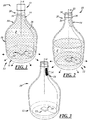
FIG. 1 is a perspective view of a package in accordance with an illustrative embodiment of the present disclosure and including a container filled with a product, and a use indicator carried by the container and shown in an inactivated state responsive to an original or initial weight of the product; -
FIG. 2 is a perspective view of a product including the container ofFIG. 1 relieved of some of the product ofFIG. 1 , and with the use indicator ofFIG. 1 shown in a partially activated state responsive to reduced weight of the product; -
FIG. 3 is a perspective view of the product ofFIG. 2 , wherein the container is empty, and the use indicator is shown in an activated state responsive to absence of the product; -
FIG. 4 is a perspective view of a product in accordance with an illustrative embodiment of the present disclosure and including a container that is empty, and a use indicator carried by the container and shown in an inactivated state; -
FIG. 5 is a perspective view of a package in accordance with an illustrative embodiment of the present disclosure and including the product ofFIG. 4 , with the container filled with product and enclosed by a closure, and with the use indicator shown in an activated state responsive to pressure within the closed package; -
FIG. 6 is an exploded perspective view of the package ofFIG. 5 , wherein the use indicator is shown in a deactivated state responsive to depressurization of the package upon or after opening of the package; -
FIG. 7 is a perspective view of a product in accordance with an illustrative embodiment of the present disclosure and including a container that is empty, and a use indicator carried by the container and shown in an inactivated state; -
FIG. 8 is a perspective view of a package in accordance with an illustrative embodiment of the present disclosure and including the product ofFIG. 7 , with the container filled with product and enclosed by a closure, and with the use indicator shown in an activated state responsive to pressure within the closed package; -
FIG. 9 is an exploded perspective view of the package ofFIG. 8 , wherein the use indicator is shown in a deactivated state responsive to depressurization of the package upon or after opening of the package; -
FIG. 10 is an exploded fragmentary perspective view of a package in accordance with an illustrative embodiment of the present disclosure and including a container that is filled with a product, a closure, and a use indicator carried by the container and shown in an inactivated state; -
FIG. 11 is a fragmentary perspective view of the package ofFIG. 10 , including the filled container enclosed by the closure, and with the use indicator shown in an activated state responsive to pressure imposed on the container by the closure; -
FIG. 12 is a fragmentary exploded perspective view of the package ofFIG. 10 , illustrating the closure removed from the container, and with the use indicator shown in a deactivated state responsive to opening of the package; -
FIG. 13 is a fragmentary exploded perspective view of a package in accordance with an illustrative embodiment of the present disclosure and including a container that is filled with a product, a closure, and a use indicator carried by the container and shown in an inactivated state; -
FIG. 14 is a fragmentary perspective view of the package ofFIG. 13 , illustrating the closure coupled to the container and the use indicator shown in the activated state responsive to the coupling of the closure to the container; -
FIG. 15 is a fragmentary exploded perspective view of the package ofFIG. 13 , illustrating the closure removed from the container, and with the use indicator shown in a deactivated state responsive to opening of the package, for example, via removal of the closure from the container; -
FIG. 16 is a perspective view of a package in accordance with an embodiment of the present invention and including a container that is filled with a flowable product, a closure coupled to the container, and a use indicator carried by the package; and -
FIG. 17 is a bottom view of the container ofFIG. 16 , illustrating a display and a microcontroller coupled to one another and carried by a punt of the container. -
FIG. 1 illustrates apackage 10 in accordance with an illustrative embodiment of the disclosure useful for understanding the invention as including acontainer 12, aclosure 13 for thecontainer 12, an authentic or original material or product P filling thecontainer 12, and anindicator 14 carried by thecontainer 12. As will be described in further detail below, theindicator 14 may facilitate evidencing of efforts to tamper with thepackage 10, by being responsive to a change in a state of thecontainer 12 to irreversibly change or modify an optical or visual characteristic visible from outside thecontainer 12. The change in state of thecontainer 12 may include opening of thecontainer 12 and/or dispensing of product out of thecontainer 12. - The
indicator 14 may provide a counterfeit deterrence feature that provides evidence that an original package has been used. More specifically, theindicator 14 may indicate design-intent use of thecontainer 12, like container opening and/or product dispensing, such that a purchaser can see that thecontainer 12 has been "used" after thecontainer 12 was originally packaged with the product P carried therein and theclosure 13 coupled thereto. For example, thepackage 10 may be sealed by a beverage manufacturer, delivered to a customer, opened, and then partially or completely emptied of its original flowable product P. Thereafter, if counterfeiters attempt to refill the emptiedcontainer 12 with counterfeit product and repackage thepackage 10 with the closure 13 (with or without closure seals or the like), the refilled and repackagedpackage 10 will include the state modifiedindicator 14 as evidence that thepackage 10 is not original and, instead, has been refilled and repackaged. In other words, thecontainer 12 orpackage 10 are permanently or irreversibly tagged as being a once-fillable container or package. Over time, purchasers will become educated to spot refilled counterfeit packages. Thus, counterfeiters will be deterred from offering counterfeit packages to such educated purchasers. - The
container 12 may be of one-piece integrally formed construction, for example, metal, glass, ceramic, or plastic construction. (The term "integrally formed construction" does not exclude one-piece integrally molded layered glass constructions of the type disclosed for example inU.S. Patent 4,740,401 , or one-piece glass bottles to which other structure is added after the bottle-forming operation.) Thecontainer 12 may be fabricated in press-and-blow or blow-and-blow glass container manufacturing operations, or in a plastic injection and/or blow molding operation, or in any other suitable manner. - The
container 12 may be of any suitable shape, and may include a jug, jar, bottle, other food or beverage container, or any other suitable container. Thecontainer 12 may include abase 15 on which thecontainer 12 may be supported, abody 16 extending axially from thebase 15, ashoulder 18 extending radially and axially from thebody 16, and aneck 20 extending axially from theshoulder 18. As used herein, the term axial includes oriented generally along a longitudinal axis of the closure, container, or package and may include but is not limited to a direction that is strictly parallel to a container longitudinal central axis A. Thebody 16 and theneck 20 may be generally cylindrical, as illustrated, or they may be tapered or of any other suitable shape. - With reference to
FIG. 2 , theneck 20 may include a lip or axialoutward end surface 22, and aninterior surface 26. Theneck 20 also may include a finish, which may include acapping flange 28, and one or more threads orthread segments 30, or the like for coupling to the closure 13 (FIG. 1 ). - The product P may be dispensably disposed within the
container 12 of thepackage 10. For example, a product manufacturer may fill thecontainer 12 with the authentic or original flowable product P at a packaging plant and close thecontainer 12 with theclosure 13, which may be fastened to theneck 20 of thecontainer 12 in any suitable manner and may be sealed thereto with wax, paper or plastic seal, or any other suitable seal (none shown). Thereafter, theclosure 13 may be removed and the product P dispensed out of thecontainer 12 through theneck 20. Theclosure 13 may include a cap, cork, plug, or any other suitable type of closure. The product P may include a liquid or solid, for example, a beverage, for instance, beer, wine, liquor, soda, or any other suitable beverage or liquid, or a food of any kind. - With reference to
FIG. 1 , theindicator 14 may include any suitable components and may be carried in any suitable location(s) of thecontainer 12, internally and/or externally of thecontainer 12. One or more portions of theindicator 14 may be non-removably secured to thecontainer 12, or carried by thecontainer 12 in any other suitable manner. The terminology "non-removably secured" includes a manner in which theindicator 14 is, by design-intent, not intended to be removed from thecontainer 12 without damaging thecontainer 12 and/orindicator 14 or otherwise visibly compromising the structural and/or functional integrity of either or both. - The
indicator 14 is responsive to a change of pressure in thecontainer 12. For example, theindicator 14 may be responsive to a change in pressure in thecontainer 12 as a result of opening of thepackage 10, for example via partial or complete removal of theclosure 13 from thecontainer 12. In another example useful for understanding the invention, theindicator 14 also or instead may be responsive to a change in weight of the original flowable product P in thecontainer 12 as a result of dispensing of the product P from thecontainer 12 after thepackage 10 has been opened. Theindicator 14 may further include asensor 32 that may be carried by thecontainer 12, and adisplay 34 carried by thecontainer 12 and electrically coupled to thesensor 32. Thesensor 32 and thedisplay 34 may be directly coupled to one another but, in the illustrated embodiment, theindicator 14 also may include anelectrical conductor 36 that may be carried by thecontainer 12, for example, for electrically coupling thesensor 32 and thedisplay 34 together. - In an example useful for understanding the invention, the
sensor 32 may be carried by thecontainer 12 in any suitable manner to detect one or more forces acting on thecontainer 12. The weight of the product P imposes a force on thecontainer 12 such that thecontainer 12 may flex (albeit imperceptibly to the eye) such that mechanical stresses in thebody 16 and/orbase 15 of thecontainer 12 may be measured. Thesensor 32 may include one or more piezoelectric sensors to detect forces and/or changes in forces imposed on thecontainer 12, for instance, via sensed stress and/or change in stresses in one or more walls of thecontainer 12. Accordingly, thesensor 32 may output voltage and/or changes in voltages in response (proportional or otherwise) to the forces, stresses, and changes therein. Thesensor 32 may be carried by thebase 15 of thecontainer 12. More specifically, thesensor 32 may be coupled to an interior surface or an exterior surface of a wall of thebase 15, for instance, by being adhered to the base wall, placed in or snap fit to a corresponding debossment or depression in the base wall, or coupled in any other suitable manner thereto. Thesensor 32 and a surrounding portion of thecontainer 12 may be covered by an epoxy layer, a silicon layer, a screen printed layer, or the like. In other examples useful for understanding the invention, thesensor 32 may be carried by other portions of thecontainer 12, for instance, thebody 16 or theshoulder 18 in a similar manner. - The
conductor 36 may include a wire, a trace, and/or the like, and may be carried by thecontainer 12 in any suitable manner to electrically couple thedisplay 34 to thesensor 32. For example, theconductor 36 may be carried by corresponding walls of thebase 15 andbody 16. More specifically, theconductor 36 may be adhered to the walls, molded into and/or through the walls, fit in corresponding channels in the walls, printed to the walls, or coupled thereto in any other suitable manner. - The
display 34 may be carried by thecontainer 12 in any suitable manner and electrically coupled to thesensor 32, for instance, via theconductor 36, to receive voltage therefrom that may be used by thedisplay 34 to modify an optical or visual appearance or characteristic associated with the product or package including thecontainer 12 and/or theindicator 14. The characteristic may include opacity or transparency, color, or any other characteristic visible to the eye. Thedisplay 34 may include one or more electrochromic (or electrochromatic) devices, which may include electrically switchable or variable glass or glazing that has switchable or variable light transmission properties depending on voltage applied thereto. For example, in one or more embodiments, the electrochromic device may include "Smart Glass," "EGlass," "smart sunglass," or "smart window" light transmission technology. The electrochromic device may include electrochromic polymers, and any other suitable materials. In other embodiments, thedisplay 34 may include a liquid crystal display (LCD), or the like. - Accordingly, in one example, the
display 34 may be activated or deactivated to selectively modify transparency of at least a portion of theindicator 14 orcontainer 12. The illustrateddisplay 34 is of generally rectangular shape for selective coverage of thecontainer 12, but may be of any other suitable shape, size, or configuration. Thedisplay 34 may be coupled to an interior surface or an exterior surface of a wall of theneck 20, for instance, by being adhered to the neck wall, placed in or snap fit to a corresponding debossment or depression in the neck wall, or coupled in any other suitable manner thereto. Thedisplay 34 and a surrounding portion of thecontainer 12 may be covered by an epoxy layer, a silicon layer, a screen printed layer, or the like. In other embodiments, thesensor 34 may be carried by other portions of thecontainer 12, for instance, theshoulder 18, thebody 16, or the base 15 in a similar manner. - Prior to filling of the
container 12 with the product P, thedisplay 34 may be in a default state. For example, thecontainer 12 may be empty and thedisplay 34 may be opaque. As the product P is introduced into thecontainer 12, thesensor 32 detects the increasing weight of the product P and outputs an increasing voltage to thedisplay 34 to modify the transparency or opacity of thedisplay 34 to become transparent. As illustrated inFIG. 1 , thedisplay 34 is shown in a neutral or inactivated state, which, in the illustrated example embodiment is transparent. - But, with reference to
FIG. 2 , upon initial opening of thepackage 10 and/or upon dispensing of the original flowable product P, theindicator 14 is adapted irreversibly to modify a state of a visual characteristic visible from outside of thecontainer 12 to advise a user that the authentic product P has been dispensed from thecontainer 12. Accordingly, theindicator 14 will exhibit a second state of the visual characteristic that is different from the first state of the visual characteristic. The terminology "irreversible" includes a manner in which theindicator 14 is, by design-intent, modifiable in one direction, for example, transparent to opaque and not back to transparent, or in another example, opaque to transparent and not back to opaque. Activation and deactivation of theindicator 14 makes it possible to modify a characteristic, like transparency of theindicator 14 and/orcontainer 12. - For example, the
display 34 of theindicator 14 is illustrated inFIG. 2 in a state different from that shown inFIG. 1 . More specifically, thedisplay 34 is shown in a partially deactivated state, which corresponds to a partially emptied state of thecontainer 12. In particular, thedisplay 34 may exhibit modified or different opacity or transparency as a result of at least some of the product P having been dispensed from thecontainer 12. The reduced amount of the product P results in a reduced force imposed by the product P on thecontainer 12, and a concomitant change in stress in thecontainer 12, for instance, in the container wall(s). Accordingly, thesensor 32 outputs a different voltage level to thedisplay 34, which, in turn, irreversibly modifies the visual characteristic to the different state, for instance, to a partially opaque or partially transparent state. - In one embodiment, the
sensor 32 or thedisplay 34 may include an integrated latch-type electrical circuit or a fusible link to prevent voltage from passing from thesensor 32 to thedisplay 34 ever again, thus preventing the transparency of thedisplay 34 from ever again changing. In another embodiment, a microcontroller (not separately shown) with embedded code may be integrated with or coupled to thesensor 32. The microcontroller would function so that once the voltage output from thesensor 32 to thedisplay 34 changed (increased or decreased, depending on the specific configuration desired) the microcontroller would never again allow the voltage output to revert or return to any previous output level. For example, if thesensor 32 initially outputs zero voltage to thedisplay 34 when thecontainer 12 is full, as thecontainer 12 is emptied, the weight of the product therein would change, thereby causing an increase in the voltage output from thesensor 32 to thedisplay 34. This increase in voltage would cause a change in transparency of thedisplay 34, but if thecontainer 12 is then refilled, even after only being half empty, the coded microcontroller would function to prevent the voltage output to return to zero. Instead, in response to the increase in weight from refilling, after the decrease in weight from dispensing, the microcontroller could function to output even more voltage to thedisplay 34 to completely change the transparency of thedisplay 34, permanently or irreversibly. - In another example, and referring to
FIG. 3 , thedisplay 34 of theindicator 14 is illustrated in another state different from that shown inFIGS. 1 and 2 . More specifically, thedisplay 34 is shown in a deactivated state, which corresponds to a fully emptied state of thecontainer 12. In response to the weight change, thesensor 32 outputs a different voltage level to thedisplay 34, which, in turn, irreversibly modifies the visual characteristic to the other different state, for instance, an opaque or non-transparent state. - In another embodiment, the initial state of the
display 34 corresponding to a full container may be opaque or non-transparent, and the final state of thedisplay 34 corresponding to an empty container may be transparent. The intermediate state(s), as illustrated inFIG. 2 , corresponding to a partially full container, may be partially transparent. - In the examples of
FIGS. 1-3 useful for understanding the invention, thedisplay 34 is carried by a container sidewall, more specifically, the sidewalls of thecontainer shoulder 18 andneck 20, and thesensor 32 is carried by a base wall of thecontainer 12, more specifically, the wall of thecontainer base 15. In other embodiments, for example those discussed below, thedisplay 34 may be carried by a sidewall of thebody 16 or the container base wall, and thesensor 32 may be carried by a sidewall of thecontainer 12, or theclosure 13. -
FIGS. 4-6 illustrate another illustrative embodiment of a product 111 (FIG. 4 ) and a package 110 (FIGS. 5-6 ) useful for understanding the invention. This embodiment is similar in many respects to the embodiment ofFIGS. 1-3 and like numerals between the embodiments generally designate like or corresponding elements throughout the several views of the drawing figures. Accordingly, the descriptions of the embodiments are incorporated into one another. Additionally, the description of the common subject matter generally may not be repeated here. - With reference to
FIG. 4 , aproduct 111 includes acontainer 112 and anindicator 114 carried by thecontainer 112. Thecontainer 112 may include a base 115, abody 116 extending from the base 115, ashoulder 118 extending from thebody 116, and aneck 120 extending from theshoulder 118. Theindicator 114 may include asensor 132 coupled to a wall of the base 115, aconductor 136 carried in walls of the base 115 and thebody 116, and adisplay 134 coupled to the walls of thebody 116 and theshoulder 118. As shown, thedisplay 134 may be in the form of a product logo, but may be of any other suitable shape, size, and/or configuration. Prior to filling of thecontainer 112, thedisplay 134 may be in a default state. For example, thecontainer 112 may be empty and thedisplay 134 may be transparent. - With reference to
FIG. 5 , however, product P may be introduced into thecontainer 112, thecontainer 112 may be pressurized, and aclosure 113 may be coupled to thecontainer 112. Accordingly, the interior of thepackage 110 may be pressurized. In this embodiment, thesensor 132 may detect the weight of the product P and/or the pressure in thepackage 110 via forces or mechanical stresses in the container, for instance, in the container wall(s). In response, thesensor 132 outputs a voltage to thedisplay 134 to modify the transparency or opacity of thedisplay 134 to become opaque. As illustrated inFIG. 5 , thedisplay 134 is shown in an activated state, which, in the illustrated example embodiment is opaque. - But, with reference to
FIG. 6 , upon initial opening of thepackage 110 by partial or complete removal of theclosure 113, theindicator 114 is adapted irreversibly to modify a state of a characteristic of theindicator 114 that is visible from outside of thecontainer 112 to advise a user that theoriginal package 110 has been opened. Accordingly, theindicator 114 will exhibit a second state of the visual characteristic that is different from the first state of the visual characteristic. For example, thedisplay 134 of theindicator 114 is illustrated inFIG. 6 in a state different from that shown inFIG. 5 . More specifically, thedisplay 134 is shown in a deactivated state, which corresponds to an opened state of thecontainer 112. In particular, thedisplay 134 may exhibit modified or different opacity or transparency as a result of the package opening. Package opening results in a loss in pressure in the container and a concomitant reduced force on thecontainer 112 and change in stress in the container wall(s). Accordingly, thesensor 132 outputs a different voltage level to thedisplay 134, which, in turn, irreversibly modifies the visual characteristic to the different state, for instance, the transparent state. - In another embodiment, the default or inactivated state of the
display 134 corresponding to an empty container before packaging may be opaque, the activated state of the package may be transparent, and the deactivated state corresponding to an opened package may be opaque. -
FIGS. 7-9 illustrate another illustrative embodiment of a product 211 (FIG. 7 ) and package 210 (FIGS. 8-9 ) useful for understanding the invention. This embodiment is similar in many respects to the embodiment ofFIGS. 1-6 and like numerals between the embodiments generally designate like or corresponding elements throughout the several views of the drawing figures. Accordingly, the descriptions of the embodiments are incorporated into one another. Additionally, the description of the common subject matter generally may not be repeated here. - With reference to
FIG. 7 , theproduct 211 includes acontainer 212 and anindicator 214 carried by thecontainer 212. Thecontainer 212 may include abase 215, abody 216 extending from thebase 215, ashoulder 218 extending from thebody 216, and aneck 220 extending from theshoulder 218. Theindicator 214 may include asensor 232 coupled to a wall of thebase 215, aconductor 236 carried in walls of thebase 215 and thebody 216, and adisplay 234 coupled to the wall of thebody 216. As shown, thedisplay 234 may be in the form of indicia, like a product brand name, logo, slogan, or the like, but may be of any other suitable shape, size, and/or configuration. - The
indicator 214 also may include aswitch 238 in communication between thesensor 232 and thedisplay 234, for instance, in line with theconductor 236. In one embodiment, theswitch 238 may function as a close-once-only and/or open-once-only type of switch and may include, for example, an electronic latch. For instance, theswitch 238 may be configured to be closed once during filling and pressurization of thepackage 210 at the product packager's facility, and then opened once a user opens thepackage 210 where it remains in its open state and cannot be closed again even if the package is refilled and depressurized. Theswitch 238 is illustrated schematically and, as used herein, the term switch includes any suitable switch(es), semiconductor(s), circuit(s), or the like. Prior to filling of thecontainer 212, thedisplay 234 may be in a default state. For example, thecontainer 212 may be empty and thedisplay 234 may be transparent. - With reference to
FIG. 8 , however, product P may be introduced into thecontainer 212, thecontainer 212 may be pressurized, and aclosure 213 may be coupled to thecontainer 212. Accordingly, the interior of thepackage 210 may be affirmatively pressurized in any suitable manner before and during closing of thecontainer 212 with theclosure 213. Such pressurization may be instead of or in addition to passive pressurization created by the product P itself. In this embodiment, thesensor 232 may detect the weight of the product P and/or the pressure in thepackage 210 via forces or mechanical stresses in the container, for instance, in the container wall(s). In response, thesensor 232 outputs a voltage to thedisplay 234 to modify the transparency or opacity of thedisplay 234 to become opaque. As illustrated inFIG. 8 , thedisplay 234 is shown in an activated state, which, in the illustrated example embodiment is opaque. - But, with reference to
FIG. 9 , upon initial opening of thepackage 210 by partial or complete removal of theclosure 213, theindicator 214 is adapted irreversibly to modify a state of a characteristic of theindicator 214 that is visible from outside of thecontainer 212 to advise a user that theoriginal package 210 has been opened. Package opening results in a loss in pressure in thecontainer 212 and a concomitant reduced force on thecontainer 212 and change in stress in the container wall. Accordingly, thesensor 232 outputs a different voltage level, which causes theswitch 238 to permanently open or fail. In turn, the now permanently opened or failedswitch 238 cuts off voltage to thedisplay 234, thereby irreversibly modifying the visual characteristic to the different state, for instance, the transparent state. -
FIGS. 10-12 illustrate another illustrative embodiment of apackage 310 useful for understanding the invention. This embodiment is similar in many respects to the embodiment ofFIGS. 1-9 and like numerals between the embodiments generally designate like or corresponding elements throughout the several views of the drawing figures. Accordingly, the descriptions of the embodiments are incorporated into one another. Additionally, the description of the common subject matter generally may not be repeated here. - With reference to
FIG. 10 , thepackage 310 includes acontainer 312, anindicator 314 carried by thecontainer 312, and aclosure 313 coupled to thecontainer 312. Thecontainer 312 may include abody 316, ashoulder 318 extending from thebody 316, and aneck 320 extending from theshoulder 318. Theindicator 314 may include asensor 332 coupled to a wall of theneck 320, aconductor 336 carried in walls of theneck 320,shoulder 318, andbody 316, and a display 334 coupled to the wall of thebody 316 and/orshoulder 318. Thesensor 332 may include a pressure sensor that may sense pressure imposed on thecontainer 312 by theclosure 313, or may include a proximity sensor, switch, or any other suitable device(s), that may cooperate with a corresponding portion of theclosure 313. In one embodiment, thesensor 332 may include an RFID sensor that may cooperate with an RFID tag on the closure, or vice-versa. - Prior to filling of the
container 312 and coupling of theclosure 313 thereto, the display 334 may be in a default state. For example, the display 334 may be transparent. - With reference to
FIG. 11 , however, theclosure 313 may be coupled to thecontainer 312. In one embodiment, thesensor 332 may detect the pressure imposed on thecontainer neck 320 by theclosure 313 being inserted therein, via forces or mechanical stresses in the container. In another embodiment, thesensor 332 may detect presence of theclosure 313 coupled to thecontainer neck 320. In response, thesensor 332 outputs a voltage to the display 334 to modify the transparency or opacity of the display 334 to become opaque. As illustrated inFIG. 11 , the display 334 is shown in an activated state, which, in the illustrated example embodiment is opaque. - But, with reference to
FIG. 12 , upon initial opening of thepackage 310 by partial or complete removal of theclosure 313 from thecontainer 312, theindicator 314 is adapted irreversibly to modify a state of a characteristic of theindicator 314 that is visible from outside of thecontainer 312 to advise a user that theoriginal package 310 has been opened. Package opening results in a reduction in pressure in thecontainer neck 320 and a concomitant reduced force on thecontainer 312 and change in stress in the container wall. Accordingly, thesensor 332 outputs a different voltage level to the display 334, which, in turn, irreversibly modifies the visual characteristic to the different state, for instance, the transparent state. Thesensor 332 is configured to be activated only once. -
FIGS. 13-15 illustrate another illustrative embodiment of apackage 410 useful for understanding the invention. This embodiment is similar in many respects to the embodiment ofFIGS. 1-12 and like numerals between the embodiments generally designate like or corresponding elements throughout the several views of the drawing figures. Accordingly, the descriptions of the embodiments are incorporated into one another. Additionally, the description of the common subject matter generally may not be repeated here. - With reference to
FIG. 13 , thepackage 410 includes acontainer 412, anindicator 414 carried by thecontainer 412, and aclosure 413 for coupling to thecontainer 412. Thecontainer 412 may include abody 416, ashoulder 418 extending from thebody 416, and aneck 420 extending from theshoulder 418. Theindicator 414 may include asensor 432 coupled to a wall of theneck 420, aconductor 436 carried in walls of theneck 420,shoulder 418, andbody 416, and adisplay 434 coupled to the wall of thebody 416. Theindicator 414 also may include apower source 440, for instance, one or more batteries, quartz piezoelectrics, capacitors, solar cells, or any other suitable supply of electricity. Theclosure 413 may include aswitch activator 442, for instance, a magnet, a ferrous metal, or any other suitable switch activation component. Thesensor 432 may include a switch, for instance, a reed switch, or any other suitable device(s), that may cooperate with theswitch activator 442. - Prior to filling of the
container 412 and coupling of theclosure 413 thereto, thedisplay 434 may be in a default state. For example, thedisplay 434 may be transparent. - With reference to
FIG. 14 , however, theclosure 413 may be coupled to thecontainer 412 and theswitch activator 442 may be located next to theswitch 432 thereby causing theswitch 432 to close and complete a circuit from thepower source 440 to thedisplay 434. The voltage from thepower source 440 to thedisplay 434 modifies the transparency or opacity of thedisplay 434. As illustrated inFIG. 14 , thedisplay 434 is shown in an activated state, which, in the illustrated example embodiment is opaque, for example, for brand reinforcement - But, with reference to
FIG. 15 , upon initial opening of thepackage 410 by partial or complete removal of theclosure 413 from thecontainer 412, theindicator 414 is adapted irreversibly to modify a state of a characteristic of theindicator 414 that is visible from outside of thecontainer 412 to advise a user that theoriginal package 410 has been opened. Package opening results in permanent opening of theswitch 432 and a concomitant cutoff of voltage from thepower source 440 to thedisplay 434. Accordingly, thedisplay 434 reverts irreversibly to its default or deactivated state, for a concomitant irreversible modification of the visual characteristic to the different state, for instance, the transparent state. Theswitch 432 may be a latch, or the like. -
FIGS. 16-17 illustrate an illustrative embodiment of a package according to the invention. This embodiment is similar in many respects to the embodiment ofFIGS. 1-15 and like numerals between the embodiments generally designate like or corresponding elements throughout the several views of the drawing figures. Accordingly, the descriptions of the embodiments are incorporated into one another. Additionally, the description of the common subject matter generally may not be repeated here. - With reference to
FIG. 16 , thepackage 510 includes acontainer 512, anindicator 514, at least a portion of which is carried by thecontainer 512, and aclosure 513 for coupling to thecontainer 512. Thecontainer 512 may include abase 515, abody 516 extending from thebase 515, ashoulder 518 extending from thebody 516, and a neck 520 extending from theshoulder 518. The base 515 may include a bottom 515a, which may include an annular surface, and a push-up or punt 515b extending radially and axially away from the bottom 515a. - The
indicator 514 includes a sensor 532 that is carried by theclosure 513, for example, coupled to a base wall thereof, or in any other suitable manner. Theindicator 514 also includes afirst microcontroller 533, which is electrically coupled to the sensor 532, and may include a radio frequency (RF) microcontroller with afirst antenna 536a. Themicrocontroller 533, and theantenna 536a, are carried by theclosure 513, for example, coupled to a base wall thereof, or in any other suitable manner. The sensor 532 includes a piezoelectric sensor, or any other suitable sensor to measure pressure in thepackage 510, for example, after thecontainer 512 has been filled with a product and theclosure 513 sealingly coupled thereto to form thepackage 510. - The
indicator 514 further includes adisplay 534 that is carried by thecontainer 512, for example, coupled to a wall of thebase 515 of thecontainer 512. Theindicator 514 also includes asecond microcontroller 535, which is electrically coupled to thedisplay 534, and may include an RF microcontroller with asecond antenna 536b. Themicrocontroller 535, and theantenna 536b, are carried by thecontainer 512, for example, coupled to thebase 515, or in any other suitable manner. More specifically, thedisplay 534 and themicrocontroller 535 may be carried externally of thecontainer 512, for instance, in thepunt 515b of thecontainer 512. Thedisplay 534 andmicrocontroller 535 may be protected from tampering, for example, by applying a non-conductive resin thereover and in contact with thecontainer 512 to completely cover the components. - The
microcontrollers microcontrollers indicator 514. As used herein, the term instructions may include, for example, control logic, computer software and/or firmware, programmable instructions, or other suitable instructions. Themicrocontrollers 533, 555 may be RF enabled, and/or may be wired together, or may be integrated as a single microcontroller. - The
indicator 514 also may include one or more power sources. In a first example, theindicator 514 may include afirst power source 540a electrically coupled to thefirst microcontroller 533 and/or the pressure sensor 532 in any suitable manner. In a second example, theindicator 514 may include asecond power source 540b electrically coupled to thesecond microcontroller 535 and/or thedisplay 534 in any suitable manner. Eachpower source - Upon initial opening of the
package 510 by partial or complete removal of theclosure 513 from thecontainer 512, theindicator 514 is adapted irreversibly to modify a state of a characteristic of theindicator 514 that is visible from outside of thecontainer 512 to advise a user that theoriginal package 510 has been opened. Package opening results in a reduction in pressure in thepackage 510 and a concomitant reduced force on the pressure sensor 532. Accordingly, the sensor 532 outputs a different voltage level to thefirst RF microcontroller 533, which, in turn, may use thefirst antenna 536a to communicate a corresponding signal wirelessly to thesecond RF microcontroller 535. In turn, thesecond RF microcontroller 535 may use thesecond antenna 536b to receive the signal and then may process the received signal to generate an output signal for communication to thedisplay 534 to modify the visual characteristic to the different state, for instance, display of a date and/or time that the closure was opened. The second RF microcontroller and/or thedisplay 534 is/are configured to be activated only once so that the date and/or time of opening of the package is irreversibly displayed. - According to other embodiments of the present disclosure, there are provided one or more methods of producing and using a package useful for understanding the invention. The method of producing a package includes coupling at least part of an indicator to a container, wherein the indicator includes a sensor and a display, filling the container with an original flowable product, and closing the container with a closure. The closing step may include pressurizing the package in any suitable manner before and during application of the closure to the container. After one or both of the filling or closing steps, the display exhibits an initial state of a visual characteristic of a plurality of states of the visual characteristic. The method of using that product includes initially opening the package, and also may include dispensing at least some of the original flowable product. Responsive to at least one of the opening or dispensing, the display exhibits another state of the visual characteristic different from and irreversible to the initial state of the visual characteristic.
- There thus has been disclosed a container and a use indicator carried by the container and that fully satisfies all of the objects and aims previously set forth. The disclosure has been presented in conjunction with several illustrative embodiments, and additional modifications and variations have been discussed. Other modifications and variations readily will suggest themselves to persons of ordinary skill in the art in view of the foregoing discussion.
Claims (6)
- A package (510) that includes:a container (512);an original flowable product (P) dispensably disposed within the container;a closure (513) coupled to the container to close the container;wherein the closure carries a pressure sensor (532) and a first microcontroller (533) electrically coupled to the pressure sensor; and wherein the package includes:an indicator (514) carried by the container, and responsive to a change in pressure in the package to irreversibly modify a visual characteristic visible from outside the container,wherein the indicator displays an initial state of the visual characteristic, and then displays another state irreversible to the initial state responsive to the change of the pressure in the package; andwherein the indicator includes a second microcontroller (535) carried by the container and in communication with the first microcontroller, and a display (534) carried by the container and electrically coupled to the second microcontroller.
- The package set forth in claim 1 wherein the display is an electrochromic device.
- The package set forth in claim 2, wherein the display includes the electrochromic device configured in the form of indicia.
- The package set forth in one of claims 1 to 3 wherein the visual characteristic is transparency of at least a portion of the indicator or the container.
- The package set forth in claim 1 wherein the visual characteristic is at least one of a date or time display.
- The package set forth in one of claims 1 to 5, wherein at least a portion of the indicator is non-removably secured to the container.
Priority Applications (2)
| Application Number | Priority Date | Filing Date | Title |
|---|---|---|---|
| PL13786053T PL2922768T3 (en) | 2012-11-21 | 2013-10-17 | Container having a use-evident device |
| EP18185441.5A EP3412592A1 (en) | 2012-11-21 | 2013-10-17 | Container having a use-evident device |
Applications Claiming Priority (2)
| Application Number | Priority Date | Filing Date | Title |
|---|---|---|---|
| US13/683,475 US8830076B2 (en) | 2012-11-21 | 2012-11-21 | Container having a use-evident device |
| PCT/US2013/065454 WO2014081520A1 (en) | 2012-11-21 | 2013-10-17 | Container having a use-evident device |
Related Child Applications (2)
| Application Number | Title | Priority Date | Filing Date |
|---|---|---|---|
| EP18185441.5A Division EP3412592A1 (en) | 2012-11-21 | 2013-10-17 | Container having a use-evident device |
| EP18185441.5A Division-Into EP3412592A1 (en) | 2012-11-21 | 2013-10-17 | Container having a use-evident device |
Publications (2)
| Publication Number | Publication Date |
|---|---|
| EP2922768A1 EP2922768A1 (en) | 2015-09-30 |
| EP2922768B1 true EP2922768B1 (en) | 2018-09-05 |
Family
ID=49517706
Family Applications (2)
| Application Number | Title | Priority Date | Filing Date |
|---|---|---|---|
| EP13786053.2A Not-in-force EP2922768B1 (en) | 2012-11-21 | 2013-10-17 | Container having a use-evident device |
| EP18185441.5A Withdrawn EP3412592A1 (en) | 2012-11-21 | 2013-10-17 | Container having a use-evident device |
Family Applications After (1)
| Application Number | Title | Priority Date | Filing Date |
|---|---|---|---|
| EP18185441.5A Withdrawn EP3412592A1 (en) | 2012-11-21 | 2013-10-17 | Container having a use-evident device |
Country Status (21)
| Country | Link |
|---|---|
| US (1) | US8830076B2 (en) |
| EP (2) | EP2922768B1 (en) |
| CN (1) | CN104781157A (en) |
| AR (1) | AR093534A1 (en) |
| AU (1) | AU2013348376B2 (en) |
| BR (1) | BR112015011102A2 (en) |
| CA (1) | CA2889444C (en) |
| CL (1) | CL2015001334A1 (en) |
| ES (1) | ES2699959T3 (en) |
| MX (1) | MX357326B (en) |
| MY (1) | MY170171A (en) |
| NZ (2) | NZ735984A (en) |
| PE (2) | PE20191573A1 (en) |
| PH (1) | PH12015500768A1 (en) |
| PL (1) | PL2922768T3 (en) |
| RU (1) | RU2015124035A (en) |
| SG (1) | SG11201503166TA (en) |
| TW (1) | TWI611988B (en) |
| UA (1) | UA114537C2 (en) |
| WO (1) | WO2014081520A1 (en) |
| ZA (1) | ZA201503049B (en) |
Families Citing this family (25)
| Publication number | Priority date | Publication date | Assignee | Title |
|---|---|---|---|---|
| ES2988402T3 (en) | 2012-06-25 | 2024-11-20 | Gecko Health Innovations Inc | Devices, systems and methods for monitoring therapeutic compliance and patient interaction |
| KR20140124283A (en) * | 2013-04-16 | 2014-10-24 | 삼성디스플레이 주식회사 | Nusing bottle using transparent flexible display |
| US11542080B2 (en) * | 2013-05-07 | 2023-01-03 | BBB Holding Company | Track and trace packaging and systems |
| AU2014312428B2 (en) | 2013-08-28 | 2018-10-11 | Gecko Health Innovations, Inc. | Devices, systems, and methods for adherence monitoring and devices, systems, and methods for monitoring use of consumable dispensers |
| WO2015143202A1 (en) * | 2014-03-19 | 2015-09-24 | Chromera, Inc. | An intelligent label device and method |
| AU2015201554A1 (en) * | 2014-04-07 | 2015-10-22 | International Connect Group (Icg) Pty Ltd | Disposable packaging with an output device for displaying advertising material |
| WO2016036230A1 (en) * | 2014-09-03 | 2016-03-10 | Garcia Lecuona Gerardo Ismael | Electronic device for checking the legitimate origin of the liquid contained in containers |
| FR3031090B1 (en) * | 2014-12-29 | 2017-01-20 | Commissariat Energie Atomique | DEVICE FOR SEALING A CONTAINER COMPRISING A COLLAR |
| US9367849B1 (en) | 2015-05-21 | 2016-06-14 | Owens-Brockway Glass Container Inc. | Packaging authentication |
| EP3103738A1 (en) * | 2015-06-11 | 2016-12-14 | Cryovac, Inc. | Leak detection system |
| CA2994152C (en) * | 2015-07-31 | 2021-08-10 | Dornoch Medical Systems, Inc. | Medical waste fluid collection and disposal system |
| FR3050189B1 (en) * | 2016-04-15 | 2020-05-08 | Commissariat A L'energie Atomique Et Aux Energies Alternatives | SECURITY DEVICE FOR SECURING A CONTAINER |
| CN106395052B (en) * | 2016-06-21 | 2018-03-20 | 重庆兆峰玻璃晶品有限公司 | False proof glaze bottle |
| CN106395076B (en) * | 2016-06-21 | 2018-02-13 | 重庆强大巴郡知识产权服务有限公司 | Glass wine bottle method for anti-counterfeit |
| EP3336011A1 (en) * | 2016-12-15 | 2018-06-20 | Anheuser-Busch InBev S.A. | Smart packaging for beverage |
| FR3063490B1 (en) * | 2017-03-02 | 2022-02-25 | Tracking Pack | REUSABLE BAG WITH ELECTRONIC CHIP. |
| PL3398881T3 (en) * | 2017-05-05 | 2024-09-23 | Element International Trade Inc. | SYSTEM |
| US10643117B2 (en) | 2017-08-23 | 2020-05-05 | Midwest Innovative Products, Llc | Electronic device for attachment to a beverage container |
| US12007754B2 (en) | 2018-03-30 | 2024-06-11 | G3 Enterprises, Inc. | System and methods for evaluating bottling line performance |
| AU2019245406A1 (en) * | 2018-03-30 | 2020-10-08 | G3 Enterprises, Inc. | A bottle with sensors for probing and optimizing bottling line performance |
| CN113228026A (en) * | 2019-04-15 | 2021-08-06 | 惠普发展公司,有限责任合伙企业 | Packaging door |
| JP7629731B2 (en) | 2019-09-20 | 2025-02-14 | キャリア コーポレイション | Method and system for locking and unlocking - Patents.com |
| GB202001725D0 (en) * | 2020-02-07 | 2020-03-25 | Contained Tech Uk Limited | An intrusion detector for a lorry |
| US20230419812A1 (en) * | 2020-12-02 | 2023-12-28 | Nippon Telegraph And Telephone Corporation | Cap and Detection System |
| DE102021121305A1 (en) * | 2021-08-17 | 2023-02-23 | Krones Aktiengesellschaft | Production plant for the manufacture, treatment and/or filling of containers and methods for the production control and/or plant specification thereof |
Family Cites Families (21)
| Publication number | Priority date | Publication date | Assignee | Title |
|---|---|---|---|---|
| US3399811A (en) | 1967-01-27 | 1968-09-03 | Owens Illinois Inc | Liquid pourout fitment |
| US4740401A (en) | 1987-02-02 | 1988-04-26 | Owens-Illinois Glass Container Inc. | Forming laminated glass containers from a composite encapsulated gob of molten glass |
| US6529446B1 (en) * | 1996-12-20 | 2003-03-04 | Telaric L.L.C. | Interactive medication container |
| US7041941B2 (en) * | 1997-04-07 | 2006-05-09 | Patented Medical Solutions, Llc | Medical item thermal treatment systems and method of monitoring medical items for compliance with prescribed requirements |
| US7276675B2 (en) * | 1997-04-07 | 2007-10-02 | Patented Medical Solutions, Llc | Medical item thermal treatment systems and method of monitoring medical items for compliance with prescribed requirements |
| US6226619B1 (en) | 1998-10-29 | 2001-05-01 | International Business Machines Corporation | Method and system for preventing counterfeiting of high price wholesale and retail items |
| AU2072901A (en) | 1999-12-10 | 2001-06-18 | David M Teller | Service transaction monitoring system, method, and device |
| GB0313627D0 (en) * | 2003-06-12 | 2003-07-16 | Cognifex Ltd | Containers |
| JP2007527344A (en) | 2003-06-12 | 2007-09-27 | ベンモア ベンチャーズ リミテッド | container |
| US7017807B2 (en) | 2003-09-08 | 2006-03-28 | Francis M. Claessens | Apparatus and method for detecting tampering with containers and preventing counterfeiting thereof |
| US7163311B2 (en) * | 2004-10-22 | 2007-01-16 | Kramer James F | Foodware having visual sensory stimulating or sensing means |
| WO2006064523A1 (en) | 2004-12-16 | 2006-06-22 | Gi.Bi.Effe S.R.L. | Tamper-proof box |
| SE528760C2 (en) * | 2005-05-18 | 2007-02-13 | Secure Logistics Sweden Ab | Method and apparatus for detecting intrusion into or manipulation of the contents of an enclosure |
| KR200410362Y1 (en) | 2005-12-16 | 2006-03-08 | 강성준 | Bottle with open sensing function |
| US7973664B1 (en) | 2006-08-04 | 2011-07-05 | Rexam Healthcare Packaging Inc. | Closure having RFID and foil |
| US7898422B2 (en) | 2007-10-18 | 2011-03-01 | Wine Father LLC | Tamper-resistant microchip assembly |
| WO2009116804A2 (en) | 2008-03-18 | 2009-09-24 | Park Chul | Prevention bottle using a light emitting device |
| US8040244B2 (en) | 2008-11-07 | 2011-10-18 | International Business Machines Corporation | Closure with passive electronic sensor for tamper detection and related method |
| US8284068B2 (en) * | 2009-07-14 | 2012-10-09 | Sam Johnson | Activity monitor to alleviate controlled substance abuse |
| GB201001235D0 (en) | 2010-01-26 | 2010-03-10 | Uwl Technology Ltd | Elapsed time indicator |
| US9365314B2 (en) * | 2012-11-16 | 2016-06-14 | Owens-Brockway Glass Container Inc. | Product and package with a photosensitive use-evident feature |
-
2012
- 2012-11-21 US US13/683,475 patent/US8830076B2/en active Active
-
2013
- 2013-10-17 PL PL13786053T patent/PL2922768T3/en unknown
- 2013-10-17 PE PE2019001911A patent/PE20191573A1/en unknown
- 2013-10-17 EP EP13786053.2A patent/EP2922768B1/en not_active Not-in-force
- 2013-10-17 NZ NZ735984A patent/NZ735984A/en not_active IP Right Cessation
- 2013-10-17 NZ NZ706412A patent/NZ706412A/en not_active IP Right Cessation
- 2013-10-17 AU AU2013348376A patent/AU2013348376B2/en not_active Ceased
- 2013-10-17 BR BR112015011102A patent/BR112015011102A2/en not_active Application Discontinuation
- 2013-10-17 EP EP18185441.5A patent/EP3412592A1/en not_active Withdrawn
- 2013-10-17 MY MYPI2015000790A patent/MY170171A/en unknown
- 2013-10-17 CA CA2889444A patent/CA2889444C/en not_active Expired - Fee Related
- 2013-10-17 UA UAA201506114A patent/UA114537C2/en unknown
- 2013-10-17 CN CN201380060961.5A patent/CN104781157A/en active Pending
- 2013-10-17 WO PCT/US2013/065454 patent/WO2014081520A1/en not_active Ceased
- 2013-10-17 MX MX2015005942A patent/MX357326B/en active IP Right Grant
- 2013-10-17 RU RU2015124035A patent/RU2015124035A/en not_active Application Discontinuation
- 2013-10-17 ES ES13786053T patent/ES2699959T3/en active Active
- 2013-10-17 PE PE2015000660A patent/PE20150986A1/en active IP Right Grant
- 2013-10-17 SG SG11201503166TA patent/SG11201503166TA/en unknown
- 2013-11-15 TW TW102141573A patent/TWI611988B/en not_active IP Right Cessation
- 2013-11-19 AR ARP130104252A patent/AR093534A1/en active IP Right Grant
-
2015
- 2015-04-07 PH PH12015500768A patent/PH12015500768A1/en unknown
- 2015-04-08 ZA ZA2015/03049A patent/ZA201503049B/en unknown
- 2015-05-18 CL CL2015001334A patent/CL2015001334A1/en unknown
Also Published As
| Publication number | Publication date |
|---|---|
| BR112015011102A2 (en) | 2017-07-11 |
| EP3412592A1 (en) | 2018-12-12 |
| CN104781157A (en) | 2015-07-15 |
| AU2013348376A1 (en) | 2015-04-23 |
| TW201429825A (en) | 2014-08-01 |
| MX357326B (en) | 2018-07-05 |
| UA114537C2 (en) | 2017-06-26 |
| NZ706412A (en) | 2017-10-27 |
| US8830076B2 (en) | 2014-09-09 |
| ZA201503049B (en) | 2016-11-30 |
| PL2922768T3 (en) | 2019-02-28 |
| PE20191573A1 (en) | 2019-11-04 |
| PH12015500768A1 (en) | 2015-06-08 |
| CA2889444C (en) | 2019-01-29 |
| AR093534A1 (en) | 2015-06-10 |
| ES2699959T3 (en) | 2019-02-13 |
| CL2015001334A1 (en) | 2015-10-23 |
| TWI611988B (en) | 2018-01-21 |
| NZ735984A (en) | 2019-03-29 |
| SG11201503166TA (en) | 2015-06-29 |
| US20140138276A1 (en) | 2014-05-22 |
| RU2015124035A (en) | 2017-01-10 |
| MY170171A (en) | 2019-07-09 |
| PE20150986A1 (en) | 2015-06-20 |
| CA2889444A1 (en) | 2014-05-30 |
| EP2922768A1 (en) | 2015-09-30 |
| WO2014081520A1 (en) | 2014-05-30 |
| AU2013348376B2 (en) | 2016-09-08 |
| MX2015005942A (en) | 2015-09-08 |
Similar Documents
| Publication | Publication Date | Title |
|---|---|---|
| CA2889444C (en) | Container having a use-evident device | |
| AU2019210514B2 (en) | Product and package with a photosensitive use-evident feature | |
| US9580215B2 (en) | Package or product having a use indicator | |
| US8985358B2 (en) | One piece reversible closure and container system | |
| CA2888950C (en) | Container having a dispense indicator | |
| US9409686B2 (en) | Wick to indicate package opening | |
| AU2016262987B2 (en) | Packaging authentication | |
| US20160122098A1 (en) | System For Preventing The Tampering And Re-Packaging Of Containers Made From Glass, Plastic Or Other Materials | |
| CA2810353C (en) | One piece reversible closure and container system | |
| JPH0999474A (en) | Production of unjust opening preventing cap |
Legal Events
| Date | Code | Title | Description |
|---|---|---|---|
| PUAI | Public reference made under article 153(3) epc to a published international application that has entered the european phase |
Free format text: ORIGINAL CODE: 0009012 |
|
| 17P | Request for examination filed |
Effective date: 20150414 |
|
| AK | Designated contracting states |
Kind code of ref document: A1 Designated state(s): AL AT BE BG CH CY CZ DE DK EE ES FI FR GB GR HR HU IE IS IT LI LT LU LV MC MK MT NL NO PL PT RO RS SE SI SK SM TR |
|
| AX | Request for extension of the european patent |
Extension state: BA ME |
|
| DAX | Request for extension of the european patent (deleted) | ||
| 17Q | First examination report despatched |
Effective date: 20160613 |
|
| GRAP | Despatch of communication of intention to grant a patent |
Free format text: ORIGINAL CODE: EPIDOSNIGR1 |
|
| INTG | Intention to grant announced |
Effective date: 20180601 |
|
| GRAS | Grant fee paid |
Free format text: ORIGINAL CODE: EPIDOSNIGR3 |
|
| GRAA | (expected) grant |
Free format text: ORIGINAL CODE: 0009210 |
|
| AK | Designated contracting states |
Kind code of ref document: B1 Designated state(s): AL AT BE BG CH CY CZ DE DK EE ES FI FR GB GR HR HU IE IS IT LI LT LU LV MC MK MT NL NO PL PT RO RS SE SI SK SM TR |
|
| REG | Reference to a national code |
Ref country code: GB Ref legal event code: FG4D |
|
| REG | Reference to a national code |
Ref country code: CH Ref legal event code: EP |
|
| REG | Reference to a national code |
Ref country code: AT Ref legal event code: REF Ref document number: 1037525 Country of ref document: AT Kind code of ref document: T Effective date: 20180915 |
|
| REG | Reference to a national code |
Ref country code: IE Ref legal event code: FG4D |
|
| REG | Reference to a national code |
Ref country code: DE Ref legal event code: R096 Ref document number: 602013043223 Country of ref document: DE |
|
| REG | Reference to a national code |
Ref country code: FR Ref legal event code: PLFP Year of fee payment: 6 |
|
| REG | Reference to a national code |
Ref country code: NL Ref legal event code: FP |
|
| REG | Reference to a national code |
Ref country code: LT Ref legal event code: MG4D |
|
| PG25 | Lapsed in a contracting state [announced via postgrant information from national office to epo] |
Ref country code: NO Free format text: LAPSE BECAUSE OF FAILURE TO SUBMIT A TRANSLATION OF THE DESCRIPTION OR TO PAY THE FEE WITHIN THE PRESCRIBED TIME-LIMIT Effective date: 20181205 Ref country code: GR Free format text: LAPSE BECAUSE OF FAILURE TO SUBMIT A TRANSLATION OF THE DESCRIPTION OR TO PAY THE FEE WITHIN THE PRESCRIBED TIME-LIMIT Effective date: 20181206 Ref country code: LT Free format text: LAPSE BECAUSE OF FAILURE TO SUBMIT A TRANSLATION OF THE DESCRIPTION OR TO PAY THE FEE WITHIN THE PRESCRIBED TIME-LIMIT Effective date: 20180905 Ref country code: BG Free format text: LAPSE BECAUSE OF FAILURE TO SUBMIT A TRANSLATION OF THE DESCRIPTION OR TO PAY THE FEE WITHIN THE PRESCRIBED TIME-LIMIT Effective date: 20181205 Ref country code: FI Free format text: LAPSE BECAUSE OF FAILURE TO SUBMIT A TRANSLATION OF THE DESCRIPTION OR TO PAY THE FEE WITHIN THE PRESCRIBED TIME-LIMIT Effective date: 20180905 Ref country code: RS Free format text: LAPSE BECAUSE OF FAILURE TO SUBMIT A TRANSLATION OF THE DESCRIPTION OR TO PAY THE FEE WITHIN THE PRESCRIBED TIME-LIMIT Effective date: 20180905 Ref country code: SE Free format text: LAPSE BECAUSE OF FAILURE TO SUBMIT A TRANSLATION OF THE DESCRIPTION OR TO PAY THE FEE WITHIN THE PRESCRIBED TIME-LIMIT Effective date: 20180905 |
|
| REG | Reference to a national code |
Ref country code: ES Ref legal event code: FG2A Ref document number: 2699959 Country of ref document: ES Kind code of ref document: T3 Effective date: 20190213 |
|
| REG | Reference to a national code |
Ref country code: AT Ref legal event code: MK05 Ref document number: 1037525 Country of ref document: AT Kind code of ref document: T Effective date: 20180905 |
|
| PG25 | Lapsed in a contracting state [announced via postgrant information from national office to epo] |
Ref country code: AL Free format text: LAPSE BECAUSE OF FAILURE TO SUBMIT A TRANSLATION OF THE DESCRIPTION OR TO PAY THE FEE WITHIN THE PRESCRIBED TIME-LIMIT Effective date: 20180905 Ref country code: LV Free format text: LAPSE BECAUSE OF FAILURE TO SUBMIT A TRANSLATION OF THE DESCRIPTION OR TO PAY THE FEE WITHIN THE PRESCRIBED TIME-LIMIT Effective date: 20180905 Ref country code: HR Free format text: LAPSE BECAUSE OF FAILURE TO SUBMIT A TRANSLATION OF THE DESCRIPTION OR TO PAY THE FEE WITHIN THE PRESCRIBED TIME-LIMIT Effective date: 20180905 |
|
| PG25 | Lapsed in a contracting state [announced via postgrant information from national office to epo] |
Ref country code: EE Free format text: LAPSE BECAUSE OF FAILURE TO SUBMIT A TRANSLATION OF THE DESCRIPTION OR TO PAY THE FEE WITHIN THE PRESCRIBED TIME-LIMIT Effective date: 20180905 Ref country code: AT Free format text: LAPSE BECAUSE OF FAILURE TO SUBMIT A TRANSLATION OF THE DESCRIPTION OR TO PAY THE FEE WITHIN THE PRESCRIBED TIME-LIMIT Effective date: 20180905 Ref country code: IS Free format text: LAPSE BECAUSE OF FAILURE TO SUBMIT A TRANSLATION OF THE DESCRIPTION OR TO PAY THE FEE WITHIN THE PRESCRIBED TIME-LIMIT Effective date: 20190105 Ref country code: RO Free format text: LAPSE BECAUSE OF FAILURE TO SUBMIT A TRANSLATION OF THE DESCRIPTION OR TO PAY THE FEE WITHIN THE PRESCRIBED TIME-LIMIT Effective date: 20180905 |
|
| PG25 | Lapsed in a contracting state [announced via postgrant information from national office to epo] |
Ref country code: SK Free format text: LAPSE BECAUSE OF FAILURE TO SUBMIT A TRANSLATION OF THE DESCRIPTION OR TO PAY THE FEE WITHIN THE PRESCRIBED TIME-LIMIT Effective date: 20180905 Ref country code: SM Free format text: LAPSE BECAUSE OF FAILURE TO SUBMIT A TRANSLATION OF THE DESCRIPTION OR TO PAY THE FEE WITHIN THE PRESCRIBED TIME-LIMIT Effective date: 20180905 Ref country code: PT Free format text: LAPSE BECAUSE OF FAILURE TO SUBMIT A TRANSLATION OF THE DESCRIPTION OR TO PAY THE FEE WITHIN THE PRESCRIBED TIME-LIMIT Effective date: 20190105 |
|
| REG | Reference to a national code |
Ref country code: CH Ref legal event code: PL |
|
| REG | Reference to a national code |
Ref country code: DE Ref legal event code: R097 Ref document number: 602013043223 Country of ref document: DE |
|
| REG | Reference to a national code |
Ref country code: BE Ref legal event code: MM Effective date: 20181031 |
|
| PG25 | Lapsed in a contracting state [announced via postgrant information from national office to epo] |
Ref country code: LU Free format text: LAPSE BECAUSE OF NON-PAYMENT OF DUE FEES Effective date: 20181017 |
|
| PLBE | No opposition filed within time limit |
Free format text: ORIGINAL CODE: 0009261 |
|
| STAA | Information on the status of an ep patent application or granted ep patent |
Free format text: STATUS: NO OPPOSITION FILED WITHIN TIME LIMIT |
|
| REG | Reference to a national code |
Ref country code: IE Ref legal event code: MM4A |
|
| PG25 | Lapsed in a contracting state [announced via postgrant information from national office to epo] |
Ref country code: MC Free format text: LAPSE BECAUSE OF FAILURE TO SUBMIT A TRANSLATION OF THE DESCRIPTION OR TO PAY THE FEE WITHIN THE PRESCRIBED TIME-LIMIT Effective date: 20180905 Ref country code: DK Free format text: LAPSE BECAUSE OF FAILURE TO SUBMIT A TRANSLATION OF THE DESCRIPTION OR TO PAY THE FEE WITHIN THE PRESCRIBED TIME-LIMIT Effective date: 20180905 |
|
| 26N | No opposition filed |
Effective date: 20190606 |
|
| PG25 | Lapsed in a contracting state [announced via postgrant information from national office to epo] |
Ref country code: BE Free format text: LAPSE BECAUSE OF NON-PAYMENT OF DUE FEES Effective date: 20181031 Ref country code: LI Free format text: LAPSE BECAUSE OF NON-PAYMENT OF DUE FEES Effective date: 20181031 Ref country code: CH Free format text: LAPSE BECAUSE OF NON-PAYMENT OF DUE FEES Effective date: 20181031 Ref country code: SI Free format text: LAPSE BECAUSE OF FAILURE TO SUBMIT A TRANSLATION OF THE DESCRIPTION OR TO PAY THE FEE WITHIN THE PRESCRIBED TIME-LIMIT Effective date: 20180905 |
|
| PG25 | Lapsed in a contracting state [announced via postgrant information from national office to epo] |
Ref country code: IE Free format text: LAPSE BECAUSE OF NON-PAYMENT OF DUE FEES Effective date: 20181017 |
|
| PG25 | Lapsed in a contracting state [announced via postgrant information from national office to epo] |
Ref country code: MT Free format text: LAPSE BECAUSE OF NON-PAYMENT OF DUE FEES Effective date: 20181017 |
|
| PG25 | Lapsed in a contracting state [announced via postgrant information from national office to epo] |
Ref country code: TR Free format text: LAPSE BECAUSE OF FAILURE TO SUBMIT A TRANSLATION OF THE DESCRIPTION OR TO PAY THE FEE WITHIN THE PRESCRIBED TIME-LIMIT Effective date: 20180905 |
|
| PG25 | Lapsed in a contracting state [announced via postgrant information from national office to epo] |
Ref country code: CY Free format text: LAPSE BECAUSE OF FAILURE TO SUBMIT A TRANSLATION OF THE DESCRIPTION OR TO PAY THE FEE WITHIN THE PRESCRIBED TIME-LIMIT Effective date: 20180905 Ref country code: MK Free format text: LAPSE BECAUSE OF NON-PAYMENT OF DUE FEES Effective date: 20180905 Ref country code: HU Free format text: LAPSE BECAUSE OF FAILURE TO SUBMIT A TRANSLATION OF THE DESCRIPTION OR TO PAY THE FEE WITHIN THE PRESCRIBED TIME-LIMIT; INVALID AB INITIO Effective date: 20131017 |
|
| PGFP | Annual fee paid to national office [announced via postgrant information from national office to epo] |
Ref country code: NL Payment date: 20201026 Year of fee payment: 8 |
|
| PGFP | Annual fee paid to national office [announced via postgrant information from national office to epo] |
Ref country code: IT Payment date: 20201023 Year of fee payment: 8 Ref country code: FR Payment date: 20201026 Year of fee payment: 8 Ref country code: GB Payment date: 20201027 Year of fee payment: 8 Ref country code: ES Payment date: 20201103 Year of fee payment: 8 Ref country code: DE Payment date: 20201028 Year of fee payment: 8 Ref country code: CZ Payment date: 20201006 Year of fee payment: 8 |
|
| PGFP | Annual fee paid to national office [announced via postgrant information from national office to epo] |
Ref country code: PL Payment date: 20201002 Year of fee payment: 8 |
|
| REG | Reference to a national code |
Ref country code: DE Ref legal event code: R119 Ref document number: 602013043223 Country of ref document: DE |
|
| REG | Reference to a national code |
Ref country code: NL Ref legal event code: MM Effective date: 20211101 |
|
| GBPC | Gb: european patent ceased through non-payment of renewal fee |
Effective date: 20211017 |
|
| PG25 | Lapsed in a contracting state [announced via postgrant information from national office to epo] |
Ref country code: NL Free format text: LAPSE BECAUSE OF NON-PAYMENT OF DUE FEES Effective date: 20211101 Ref country code: GB Free format text: LAPSE BECAUSE OF NON-PAYMENT OF DUE FEES Effective date: 20211017 Ref country code: DE Free format text: LAPSE BECAUSE OF NON-PAYMENT OF DUE FEES Effective date: 20220503 Ref country code: CZ Free format text: LAPSE BECAUSE OF NON-PAYMENT OF DUE FEES Effective date: 20211017 |
|
| PG25 | Lapsed in a contracting state [announced via postgrant information from national office to epo] |
Ref country code: FR Free format text: LAPSE BECAUSE OF NON-PAYMENT OF DUE FEES Effective date: 20211031 |
|
| PG25 | Lapsed in a contracting state [announced via postgrant information from national office to epo] |
Ref country code: IT Free format text: LAPSE BECAUSE OF NON-PAYMENT OF DUE FEES Effective date: 20211017 |
|
| REG | Reference to a national code |
Ref country code: ES Ref legal event code: FD2A Effective date: 20230215 |
|
| PG25 | Lapsed in a contracting state [announced via postgrant information from national office to epo] |
Ref country code: ES Free format text: LAPSE BECAUSE OF NON-PAYMENT OF DUE FEES Effective date: 20211018 |
|
| PG25 | Lapsed in a contracting state [announced via postgrant information from national office to epo] |
Ref country code: PL Free format text: LAPSE BECAUSE OF NON-PAYMENT OF DUE FEES Effective date: 20211017 |