EP2922605B1 - Improved economical waste removal system for fat, oil, and grease - Google Patents
Improved economical waste removal system for fat, oil, and grease Download PDFInfo
- Publication number
- EP2922605B1 EP2922605B1 EP13857495.9A EP13857495A EP2922605B1 EP 2922605 B1 EP2922605 B1 EP 2922605B1 EP 13857495 A EP13857495 A EP 13857495A EP 2922605 B1 EP2922605 B1 EP 2922605B1
- Authority
- EP
- European Patent Office
- Prior art keywords
- container
- storage tank
- valve
- water
- outlet
- Prior art date
- Legal status (The legal status is an assumption and is not a legal conclusion. Google has not performed a legal analysis and makes no representation as to the accuracy of the status listed.)
- Not-in-force
Links
- 239000004519 grease Substances 0.000 title claims description 15
- 239000002699 waste material Substances 0.000 title description 7
- 238000003860 storage Methods 0.000 claims description 80
- XLYOFNOQVPJJNP-UHFFFAOYSA-N water Substances O XLYOFNOQVPJJNP-UHFFFAOYSA-N 0.000 claims description 57
- 239000010797 grey water Substances 0.000 claims description 21
- 238000000034 method Methods 0.000 claims description 17
- 230000003068 static effect Effects 0.000 claims description 11
- 239000011521 glass Substances 0.000 claims description 10
- 239000010865 sewage Substances 0.000 claims description 10
- 238000007599 discharging Methods 0.000 claims description 7
- 239000007788 liquid Substances 0.000 claims description 5
- 230000005484 gravity Effects 0.000 claims description 4
- 238000004519 manufacturing process Methods 0.000 claims description 3
- 238000012544 monitoring process Methods 0.000 claims description 3
- 239000004033 plastic Substances 0.000 claims description 3
- 238000005728 strengthening Methods 0.000 claims description 3
- 230000013011 mating Effects 0.000 claims description 2
- 238000000465 moulding Methods 0.000 claims 3
- 230000003028 elevating effect Effects 0.000 claims 1
- 239000012530 fluid Substances 0.000 description 13
- 239000003921 oil Substances 0.000 description 10
- 238000000926 separation method Methods 0.000 description 9
- 239000003925 fat Substances 0.000 description 5
- 239000007787 solid Substances 0.000 description 5
- 239000000463 material Substances 0.000 description 4
- 239000002351 wastewater Substances 0.000 description 4
- 230000000712 assembly Effects 0.000 description 3
- 238000000429 assembly Methods 0.000 description 3
- 239000000356 contaminant Substances 0.000 description 3
- 238000013461 design Methods 0.000 description 3
- 238000012546 transfer Methods 0.000 description 3
- 238000012986 modification Methods 0.000 description 2
- 230000004048 modification Effects 0.000 description 2
- 230000008569 process Effects 0.000 description 2
- 230000000717 retained effect Effects 0.000 description 2
- 239000002910 solid waste Substances 0.000 description 2
- 230000004308 accommodation Effects 0.000 description 1
- 230000004888 barrier function Effects 0.000 description 1
- 238000004140 cleaning Methods 0.000 description 1
- 230000003749 cleanliness Effects 0.000 description 1
- 238000009826 distribution Methods 0.000 description 1
- 238000001746 injection moulding Methods 0.000 description 1
- 238000009434 installation Methods 0.000 description 1
- 230000003993 interaction Effects 0.000 description 1
- 230000007246 mechanism Effects 0.000 description 1
- 239000002184 metal Substances 0.000 description 1
- 239000002991 molded plastic Substances 0.000 description 1
- 238000009428 plumbing Methods 0.000 description 1
- 230000002028 premature Effects 0.000 description 1
- 238000005086 pumping Methods 0.000 description 1
- 238000013517 stratification Methods 0.000 description 1
- 238000012800 visualization Methods 0.000 description 1
Images





Classifications
-
- B—PERFORMING OPERATIONS; TRANSPORTING
- B01—PHYSICAL OR CHEMICAL PROCESSES OR APPARATUS IN GENERAL
- B01D—SEPARATION
- B01D17/00—Separation of liquids, not provided for elsewhere, e.g. by thermal diffusion
- B01D17/02—Separation of non-miscible liquids
- B01D17/0208—Separation of non-miscible liquids by sedimentation
- B01D17/0211—Separation of non-miscible liquids by sedimentation with baffles
-
- E—FIXED CONSTRUCTIONS
- E03—WATER SUPPLY; SEWERAGE
- E03F—SEWERS; CESSPOOLS
- E03F5/00—Sewerage structures
- E03F5/14—Devices for separating liquid or solid substances from sewage, e.g. sand or sludge traps, rakes or grates
- E03F5/16—Devices for separating oil, water or grease from sewage in drains leading to the main sewer
-
- Y—GENERAL TAGGING OF NEW TECHNOLOGICAL DEVELOPMENTS; GENERAL TAGGING OF CROSS-SECTIONAL TECHNOLOGIES SPANNING OVER SEVERAL SECTIONS OF THE IPC; TECHNICAL SUBJECTS COVERED BY FORMER USPC CROSS-REFERENCE ART COLLECTIONS [XRACs] AND DIGESTS
- Y10—TECHNICAL SUBJECTS COVERED BY FORMER USPC
- Y10T—TECHNICAL SUBJECTS COVERED BY FORMER US CLASSIFICATION
- Y10T137/00—Fluid handling
- Y10T137/0318—Processes
-
- Y—GENERAL TAGGING OF NEW TECHNOLOGICAL DEVELOPMENTS; GENERAL TAGGING OF CROSS-SECTIONAL TECHNOLOGIES SPANNING OVER SEVERAL SECTIONS OF THE IPC; TECHNICAL SUBJECTS COVERED BY FORMER USPC CROSS-REFERENCE ART COLLECTIONS [XRACs] AND DIGESTS
- Y10—TECHNICAL SUBJECTS COVERED BY FORMER USPC
- Y10T—TECHNICAL SUBJECTS COVERED BY FORMER US CLASSIFICATION
- Y10T137/00—Fluid handling
- Y10T137/8593—Systems
- Y10T137/86276—Movable tank
-
- Y—GENERAL TAGGING OF NEW TECHNOLOGICAL DEVELOPMENTS; GENERAL TAGGING OF CROSS-SECTIONAL TECHNOLOGIES SPANNING OVER SEVERAL SECTIONS OF THE IPC; TECHNICAL SUBJECTS COVERED BY FORMER USPC CROSS-REFERENCE ART COLLECTIONS [XRACs] AND DIGESTS
- Y10—TECHNICAL SUBJECTS COVERED BY FORMER USPC
- Y10T—TECHNICAL SUBJECTS COVERED BY FORMER US CLASSIFICATION
- Y10T29/00—Metal working
- Y10T29/49—Method of mechanical manufacture
- Y10T29/494—Fluidic or fluid actuated device making
Definitions
- the present invention relates generally to a low cost assembly and method for removal, storage and disposal of fats, oil, grease waste and, more particularly, to a system for separation of fat, oil, and/or grease from an effluent flow from a sink, permitting the passage of grey water to a sewage line. Also a method of making such assembly is claimed.
- F.O.G. removal systems are generally well known.
- JP 2002059156 discloses an F.O.G removal system comprising a container having an inlet and outlet wherein the outlet discharges grey water from the container.
- a container including one or more rotating disks formed of a plastic or like material to which oil and grease contaminants are attracted.
- the rotation of the disk in at least partially immersed conditions, allows the oil to cling to the disk, so that the oil and grease is removed from the body of the water upon rotation of the disk.
- a scraper is typically used to force the oil and grease contaminants from the opposite sides of the disk and to channel such contaminants into an attached storage collection unit.
- the above-mentioned types of devices are assembled within rigid containers and the rotating disks are in fixed positions.
- the scraper assemblies are also in fixed rigid positions. This may make servicing of the apparatus difficult, particularly since the parts to be serviced have been covered in grease and oil.
- the units may have been permanently installed in a plumbing system so field service is often required. Because of the nature of installation, the field service can be difficult. Also, because many of the parts are coated with F.O.G., servicing can be messy and time consuming. Purchase of these systems tends to be expensive and represents a significant capital investment.
- the present invention fulfills one or more of these needs in the art by providing an improved economical F.O.G. removal assembly which is low in cost, conservative in size, easy to install, easy to maintain, and minimizes the mess associated with discarding accumulated and stored F.O.G.
- one aspect of the present invention is to provide a F.O.G. removal assembly for use in kitchens, including: a container having a bottom, a top, at least one sidewall, an inlet to receive an influent flow of F.O.G. and water from a drain, and an outlet for discharging grey water from the container, wherein the inlet and outlet are spaced above the bottom and below the top, a removable storage tank mating with the container and arranged to accept F.O.G. floating on water in the container that flows out of the container, an outlet baffle arranged to direct grey water from a bottom portion of the container out of the container via the outlet, a valve in the container at an elevation such that the F.O.G.
- the container may include at least one baffle extending within the container at a level below the static water level to allow water to flow below the baffle from the inlet to the outlet but retaining F.O.G. floating on the water.
- the assembly may also include an inlet baffle. The inlet baffle directs the influent from the sink drain into the inlet
- the present invention may also be considered a method of removing F.O.G. from effluent including connecting a kitchen drain to an inlet of a container, connecting a sewage drain to an outlet in the container, the outlet being located on the container to define a static water level for liquid in the container, the container also comprising an outlet baffle arranged to direct grey water from a bottom portion of the container out of the container via the outlet, interfacing a portal on a storage tank with a valve on the container, discharging effluent water containing F.O.G. from the kitchen drain into the inlet, holding the effluent water containing F.O.G inside the container for a period to allow F.O.G.
- a further aspect of the invention is a method of making a grease removal assembly as defined in appended claim 12.
- FIGS 1 - 4 generally, show an improved economical fat, oil and grease (F.O.G.) waste removal assembly, generally designated 10, constructed according to the present disclosure.
- the assembly 10 separates F.O.G. from effluent and is sized to fit inside kitchen or other facilities and provides storage for the separated F.O.G., however, it does not need a scraper apparatus or electronic sensors in order to function properly.
- the design makes the F.O.G. removal assembly extremely economical and size conscious and, in addition, simplifies the F.O.G. transfer and storage, reducing the mess usually associated with F.O.G. separation and storage units.
- One embodiment of assembly 10 includes a container 12 and a storage tank 14.
- Container 12 and tank 14 are preferably constructed of rotomolded plastic, although they may be constructed of other suitable material or methods as well.
- the container 12 includes a bottom 16, a top 18, at least one sidewall 20, and an inlet 22 to receive an influent flow of F.O.G. and water from a sink drain.
- the container also includes an outlet 24, for discharging grey water from the container 12.
- a sight glass 52 is positioned on the front wall of container 12, above a handle 56, discussed below.
- Container 12 may also include a removable lid 15.
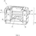
- Figure 4 is a cut-away view of one embodiment of the container 12, with the lid 15 removed.
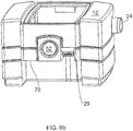
- the front wall of container 12 has a recess, that includes an overhang 70 that the tank 14 typically fits under, with the portal 36 of tank 14 lined up under an outlet 27 normally closed by a valve 28.
- Figure 4 shows an inlet baffle 30 that directs influent from the sink drain (not shown) and the inlet 22 downward and into a bottom portion 23 of the container.
- An outlet baffle 32 directs the grey water from the bottom portion 23 out of the container 12 via outlet 24 and to a drain pipe (not shown) to a sewer.
- the outlet 24 is located above the bottom 16 and below the top 18, so that the bottom of the outlet 24 defines a static water level W for liquid in the container 12.
- the container also includes a valve 28, shown in Figure 5a , at an elevation in the container 12 such that F.O.G. floating on water in the container 12 can flow from the container 12 out through the valve 28 when the liquid level in the container is raised above the valve inlet and the valve is opened by pulling handle 29 forward in the view of Figure 7 .
- a valve 28 shown in Figure 5a , at an elevation in the container 12 such that F.O.G. floating on water in the container 12 can flow from the container 12 out through the valve 28 when the liquid level in the container is raised above the valve inlet and the valve is opened by pulling handle 29 forward in the view of Figure 7 .
- Container 12 has a raised height above the static water level W, which permits a significant rise and fall of fluid level within the container 12, typically caused by an input volume level greater than that allowed by the outlet baffle 32. Surging water flows (increasing the volume of fluid through a drain pipe, and thus through attached F.O.G. separation units) are not unusual. Such circumstances occur when a sink full of water is released at once when the sink's drain stopper is removed. This volume enters the container 12 through inlet 22, raising the water height above the static water level W, at least briefly. F.O.G. is lighter than water and rises to the top of the fluid in the container 12 by the force of gravity.
- Applicant's experience teaches that a strong effluent flow directly alongside stratified fluids can peel separated F.O.G back into the waste water.
- the divider 26 shields the raised F.O.G. from that strong effluent flow.
- the F.O.G. waste removal assembly 10 is typically connected to a kitchen sink (not shown). However, other sources of effluent providing intermittent flows may be connected to assembly 10.
- the fluid separation process of the invention is applicable to input sources of F.O.G. and water that provide intermittent flows. Together, these sources are referred to herein as "sinks.”
- inlet baffle 30 and inlet 22 receive an influent flow of F.O.G. and water from a sink drain.
- Outlet 24 and outlet baffle 32 discharge grey water from the container 10.
- the bottom of outlet baffle 32 is spaced above the bottom 16. Any heavy solids may be allowed to sink to the bottom of container 12, where they may be flushed down stream through outlet 24 if the effluent flow is great enough.
- Container 12 may also include a clean out port or lid through which solid waste materials may be removed when the solids settle on the bottom 16, or to otherwise access the interior in case servicing or cleaning is needed.
- One or more dividers 26 may extend across the container 12, extending partially or fully from inlet baffle 30 to outlet baffle 32 at a level below the static water level to allow solids and water to flow below the divider 26 from the inlet 22 to the outlet 24.
- Divider 26 typically is located toward the lower portion 23 of the container 12 so that incoming fluids pass below the divider 26. As fluids enter the container 12 from inlet baffle 30, the fluids will usually have residence time within the container 12 long enough for the lighter F.O.G. to rise and separate from the remaining waste fluids. The F.O.G. stratifies to form a top layer on the waste fluids and pass through opening 72 in divider 26 toward the top of the container 12.
- the divider 26 may have a slope upward toward an opening 72 so that the F.O.G. floats upward toward and through opening 72 so the divider 26 shields the F.O.G. from the grey water flow along the bottom 23.
- the F.O.G. layer typically will accumulate above divider 26 and remain substantially undisturbed and retained within the upper container portion 21.
- Valve 28 is placed at an elevation within the container 12, typically above but close to the divider height, such that F.O.G. floating on the water in container 12 can flow from container 12 out through valve 28 when the F.O.G. level in the container is raised.
- inlet baffle 30 and outlet baffle 32 may be interchangeable and are typically constructed the same, as mirror images of each other. Therefore, the inlet 22 may serve as the outlet 24 and vice versa so that the apparatus 10 may be oriented according to the accommodations of the area surrounding the waste water piping and to accommodate a variety of kitchen drain and sewage line angle configurations.
- Effluent flow from a sink drain enters inlet baffle 30 and flows out of the lower portion of the baffle. Effluent flows as it exits the inlet baffle 30 below the stratification taking place in the upper container 21, so that any stratified F.O.G. is minimally disturbed by any strong currents in the incoming effluent flow.
- the flow travels into the body of the container, where substantial separation of F.O.G. and grey water occurs. A portion of the grey water continues below the divider 26 while F.O.G. floats to the top and is gathered into upper container 21.
- the grey water flows under and out of outlet baffle 32 and exits container 12 into the sewage drain via the outlet baffle 32, and may carry solids with it.
- Storage tank 14 of assembly 10 is best seen in Figure 6a .
- Storage tank 14 is preferably constructed of roto-molded plastic; however, other materials and methods can be used such as injection molding, metal stamping or other techniques.
- strengthening ribs 60 may be provided for adding strength and stability to the walls of the storage tank 14. This may be helpful in the rotomolded embodiment.
- Storage tank 14 includes a portal 36 for interfacing with valve 28. Typically, portal 36 is positioned below valve 28. Wheels may be added on the bottom of the tank 14 if desired to aid in its transport when full.
- the F.O.G. layer builds on top of the waste water, and as the F.O.G. builds, the boundary layer between F.O.G. and water creeps downward and may become visible in sight glass 52.
- the user determines when to reduce the F.O.G. layer, typically when the F.O.G layer is visible in most of sight glass 52.
- the user activates or retracts the valve pull 29, opening the valve between the container 12 and storage tank 14.
- the height of the valve 28 allows the F.O.G. to flow out through open valve 28 and into storage tank 14.
- the interaction between portal 36 and guide funnel 31 prevents leakage of F.O.G.
- the storage tank 14 is of sufficient size, relative to the container 12 size, so that the amount of F.O.G. and/or fluid able to reside in the container 12 above the valve level (at static effluent level W) does not exceed the volume of the tank 14, and thus the amount able to flow into the tank 14 when valve 28 is opened.
- Emptying F.O.G. into storage tank 14 usually will occur when the level of fluid and F.O.G. in the container is at a static water level W.
- the user closes the valve, for example, by replacing the valve pull 29 to its original position.
- a F.O.G. level sight glass may be included in storage tank 14, as well as container 12, allowing easy visualization of the F.O.G./water content. Sight glasses may prevent unnecessary and premature emptying of container 12 and/or storage tank 14 and easy viewing of the F.O.G. and water levels within the storage tank 14 by inspectors or operators.
- Handle 56 may be used for transporting storage tank 14 to empty the accumulated F.O.G.
- Carry handle 56 may be located on the top 63 of storage tank 14 and toward the same side as the portal 36. This places the center of gravity of storage tank 14 so that the weight distribution of the loaded tank 14 pivots the portal 36 upwards when tank 14 is lifted by handle 50. With portal 36 skewed upward, F.O.G. is not inclined to spill or leak out of the storage tank 14. Wheels may be oriented in any direction to allow storage tank 14 to roll at various angles. Portal 36 may also be used as a pour spout, allowing ease of discarding stored F.O.G. These features provide a clean and effective way to dispose of stored F.O.G. without the mess usually associated with F.O.G. tank emptying.
- the container 12 may be substantially enclosed in a separator wrap.
- the separator wrap has openings through which the inlet baffle 30 and the outlet baffle 32 connect to the sink and sewer drain. There is also a fitted hole through which the guide funnel 31 passes to allow the funnel to interface with portal 36.
- Storage tank 14 may remain outside of the separator wrap so that it may be easily accessed for F.O.G. disposal.
- the invention may also be considered a method of removing F.O.G. from effluent. Steps involved include connecting a kitchen drain (not shown) to an inlet 22 or inlet baffle 30 of a container 12 and connecting a sewage drain (not shown) to an outlet 24 or an outlet baffle 32 in the container 12.
- the method also includes placing a removable storage tank 14 with a container 12, interfacing a portal 36 on a storage tank 14 with a valve 28 on the container 12. Effluent water containing F.O.G. from the kitchen drain discharges into the inlet 22.
- the effluent water containing F.O.G is held inside the container 12 for a period to allow F.O.G.
- the valve pull 29 is engaged to open the valve 28 and F.O.G. is drained into the storage tank 14.
- the method may include monitoring a sight glass 52 on the storage tank 14 to determine when the F.O.G. level within the tank 14 is sufficient to warrant emptying, emptying the F.O.G. stored in the storage tank 14 and reestablishing the interface between the portal 36 and the valve 28.
Landscapes
- Physics & Mathematics (AREA)
- Thermal Sciences (AREA)
- Chemical & Material Sciences (AREA)
- Chemical Kinetics & Catalysis (AREA)
- Health & Medical Sciences (AREA)
- Life Sciences & Earth Sciences (AREA)
- Engineering & Computer Science (AREA)
- Hydrology & Water Resources (AREA)
- Public Health (AREA)
- Water Supply & Treatment (AREA)
- Removal Of Floating Material (AREA)
- Sewage (AREA)
Description
- The present invention relates generally to a low cost assembly and method for removal, storage and disposal of fats, oil, grease waste and, more particularly, to a system for separation of fat, oil, and/or grease from an effluent flow from a sink, permitting the passage of grey water to a sewage line. Also a method of making such assembly is claimed.
- Over the past thirty years there has been a move towards requiring food- handling facilities to have sufficient systems for servicing kitchen grease and solid waste bearing water flows. One of the largest problems, in terms of sewer system lines clogging, has been the fats, oils and grease put into the sewer system from food handling facilities. These problems and the increase in the severity of the situation in the recent past has led more and more sewer authorities to implement fats, oils, grease (hereinafter referred to as "F.O.G.") control programs. The object of many of these programs is to ensure that food handling facilities remove as much as possible of the F.O.G. from the effluent flow, thereby releasing only grey water and solids into the sewage system.
- F.O.G. removal systems are generally well known. For example,
JP 2002059156 - The above-mentioned types of devices are assembled within rigid containers and the rotating disks are in fixed positions. The scraper assemblies are also in fixed rigid positions. This may make servicing of the apparatus difficult, particularly since the parts to be serviced have been covered in grease and oil. In addition, the units may have been permanently installed in a plumbing system so field service is often
required. Because of the nature of installation, the field service can be difficult. Also, because many of the parts are coated with F.O.G., servicing can be messy and time consuming. Purchase of these systems tends to be expensive and represents a significant capital investment. - As an alternative, devices without scraper assemblies have been developed so that separation of F.O.G. and water occurs within a tank sufficient to also suffice as a storage container. These devices avoid many of the difficulties associated with the skimmer system; however, they are still expensive, difficult and messy, particularly when the storage container is full and must be emptied. These units are often too large in size to fit inside kitchen facilities so a space to accommodate the assembly size must be available for the larger separator to work. Many of these types of systems may still utilize more costly pumping apparatus for F.O.G. separation or sensing systems for accurately becoming aware of when the storage container is full. Knowing when to empty the storage container is a problem since it is often unclear how much water versus how much F.O.G. is being retained within the storage container.
- Applicant addressed some of these concerns with its more economical waste removal system, described in
U.S. Patent No. 8,273,255 to Batten. However, the F.O.G. transfer mechanism in Batten remains subject to clogging and messiness. - The process of emptying a removable storage container is known to be very messy. If the tank and storage container are attached so that leakage does not occur when the F.O.G. is passed to a storage container, then removing the storage container for disposal is often complicated and dirty. This is undesirable as it limits who can empty the storage container. Often, emptying the storage container occurs in a facility, such as a restaurant, held to certain cleanliness standards. Size, cost, ease of use and mess are all factors that may limit consumers access to and usage of F.O.G. separation assemblies.
- Accordingly, there is a need in the art for an improved method and system for separation of F.O.G. from wastewater that is simple, space saving in design, low in cost and that minimizes the mess/difficulty associated with the storage container. In addition, there is a need in the art for a low cost apparatus that does not require significant capital outlay.
- The present invention fulfills one or more of these needs in the art by providing an improved economical F.O.G. removal assembly which is low in cost, conservative in size, easy to install, easy to maintain, and minimizes the mess associated with discarding accumulated and stored F.O.G.
- Accordingly, one aspect of the present invention is to provide a F.O.G. removal assembly for use in kitchens, including: a container having a bottom, a top, at least one sidewall, an inlet to receive an influent flow of F.O.G. and water from a drain, and an outlet for discharging grey water from the container, wherein the inlet and outlet are spaced above the bottom and below the top, a removable storage tank mating with the container and arranged to accept F.O.G. floating on water in the container that flows out of the container, an outlet baffle arranged to direct grey water from a bottom portion of the container out of the container via the outlet, a valve in the container at an elevation such that the F.O.G. floating on water in the container flows out of the container through the valve when an effluent level in the container is raised above the valve level and the valve is opened, a valve control for alternating the valve between an open and closed position, and a portal on the storage tank interfacing with the valve. The container may include at least one baffle extending within the container at a level below the static water level to allow water to flow below the baffle from the inlet to the outlet but retaining F.O.G. floating on the water. The assembly may also include an inlet baffle. The inlet baffle directs the influent from the sink drain into the inlet
- The present invention may also be considered a method of removing F.O.G. from effluent including connecting a kitchen drain to an inlet of a container, connecting a sewage drain to an outlet in the container, the outlet being located on the container to define a static water level for liquid in the container, the container also comprising an outlet baffle arranged to direct grey water from a bottom portion of the container out of the container via the outlet, interfacing a portal on a storage tank with a valve on the container, discharging effluent water containing F.O.G. from the kitchen drain into the inlet, holding the effluent water containing F.O.G inside the container for a period to allow F.O.G. to float to the top of the contained effluent water, permitting grey water to flow from the container outlet to the sewage drain, intermittently discharging floating F.O.G. through the valve in the container and into the storage tank,
separating the interface between the valve and the portal by replaceably removing the storage tank, emptying the F.O.G. stored in the storage tank, replacing the storage tank next to the container, and reestablishing the interface between the valve and the portal. The method may further include monitoring a sight glass on the container to determine when the F.O.G. level within the container is sufficient to warrant emptying. A further aspect of the invention is a method of making a grease removal assembly as defined in appendedclaim 12. - These and other aspects of the present invention will become apparent to those skilled in the art after a reading of the following description of the preferred embodiment when considered with the drawings.
-
-
Figure 1 is a front perspective view of an embodiment of the invention; -
Figure 2 is a front view of an embodiment of the invention; -
Figure 3 is a side view of an embodiment of the invention; -
Figure 4 is cut away view of an embodiment of a container; -
Figure 5a is a cross-sectional bottom view of an embodiment of the container with the storage tank removed; -
Figure 6a is a top perspective view of an embodiment of the storage tank; -
Figure 6b is a front perspective view of an embodiment of the container with the lid removed; and -
Figure 7 is a cross sectional view of an embodiment of the invention. - In the following description, like reference characters designate like or corresponding parts throughout the several views. Also in the following description, it is to be understood that such terms as "forward," "rearward," "left," "right," "upwardly," "downwardly," and the like are words of convenience and are not to be construed as limiting terms.
- It will be understood that the illustrations are for the purpose of describing a preferred embodiment of the invention and are not intended to limit the invention thereto.
-
Figures 1 - 4 , generally, show an improved economical fat, oil and grease (F.O.G.) waste removal assembly, generally designated 10, constructed according to the present disclosure. Theassembly 10 separates F.O.G. from effluent and is sized to fit inside kitchen or other facilities and provides storage for the separated F.O.G., however, it does not need a scraper apparatus or electronic sensors in order to function properly. The design makes the F.O.G. removal assembly extremely economical and size conscious and, in addition, simplifies the F.O.G. transfer and storage, reducing the mess usually associated with F.O.G. separation and storage units. - One embodiment of
assembly 10 includes acontainer 12 and astorage tank 14.Container 12 andtank 14 are preferably constructed of rotomolded plastic, although they may be constructed of other suitable material or methods as well. Thecontainer 12 includes a bottom 16, a top 18, at least onesidewall 20, and aninlet 22 to receive an influent flow of F.O.G. and water from a sink drain. The container also includes anoutlet 24, for discharging grey water from thecontainer 12. Preferably, asight glass 52 is positioned on the front wall ofcontainer 12, above ahandle 56, discussed below.Container 12 may also include aremovable lid 15.Figure 4 is a cut-away view of one embodiment of thecontainer 12, with thelid 15 removed. - As seen in
Figure 6b , the front wall ofcontainer 12 has a recess, that includes anoverhang 70 that thetank 14 typically fits under, with the portal 36 oftank 14 lined up under anoutlet 27 normally closed by avalve 28. -
Figure 4 shows aninlet baffle 30 that directs influent from the sink drain (not shown) and theinlet 22 downward and into abottom portion 23 of the container. Anoutlet baffle 32 directs the grey water from thebottom portion 23 out of thecontainer 12 viaoutlet 24 and to a drain pipe (not shown) to a sewer. Theoutlet 24 is located above the bottom 16 and below the top 18, so that the bottom of theoutlet 24 defines a static water level W for liquid in thecontainer 12. - The container also includes a
valve 28, shown inFigure 5a , at an elevation in thecontainer 12 such that F.O.G. floating on water in thecontainer 12 can flow from thecontainer 12 out through thevalve 28 when the liquid level in the container is raised above the valve inlet and the valve is opened by pullinghandle 29 forward in the view ofFigure 7 . -
Figure 6a shows astorage tank 14 arranged to accept F.O.G. and water that flows out of thecontainer 12 through thevalve 28 when the liquid level in thecontainer 12 is raised above a valve inlet and the valve pull 29 is engaged to open the valve. Thestorage tank 14 includes a raised portal 36 that interfaces with thevalve 28. Thevalve 28, by way of example, is a linearly opening valve configured to reliably seal closed, even with a head of water above it.Valve 28 may include afunnel 31 to direct effluent neatly intotank 14 without spilling across the valve inlet and onto the outer valve edges. -
Container 12 has a raised height above the static water level W, which permits a significant rise and fall of fluid level within thecontainer 12, typically caused by an input volume level greater than that allowed by theoutlet baffle 32. Surging water flows (increasing the volume of fluid through a drain pipe, and thus through attached F.O.G. separation units) are not unusual. Such circumstances occur when a sink full of water is released at once when the sink's drain stopper is removed. This volume enters thecontainer 12 throughinlet 22, raising the water height above the static water level W, at least briefly. F.O.G. is lighter than water and rises to the top of the fluid in thecontainer 12 by the force of gravity. Applicant's experience teaches that a strong effluent flow directly alongside stratified fluids can peel separated F.O.G back into the waste
water. In this embodiment, thedivider 26 shields the raised F.O.G. from that strong effluent flow. - The F.O.G.
waste removal assembly 10 is typically connected to a kitchen sink (not shown). However, other sources of effluent providing intermittent flows may be connected toassembly 10. The fluid separation process of the invention is applicable to input sources of F.O.G. and water that provide intermittent flows. Together, these sources are referred to herein as "sinks." - Typically,
inlet baffle 30 andinlet 22 receive an influent flow of F.O.G. and water from a sink drain.Outlet 24 andoutlet baffle 32 discharge grey water from thecontainer 10. The bottom ofoutlet baffle 32 is spaced above the bottom 16. Any heavy solids may be allowed to sink to the bottom ofcontainer 12, where they may be flushed down stream throughoutlet 24 if the effluent flow is great enough.Container 12 may also include a clean out port or lid through which solid waste materials may be removed when the solids settle on the bottom 16, or to otherwise access the interior in case servicing or cleaning is needed. - One or
more dividers 26 may extend across thecontainer 12, extending partially or fully frominlet baffle 30 to outlet baffle 32 at a level below the static water level to allow solids and water to flow below thedivider 26 from theinlet 22 to theoutlet 24.Divider 26 typically is located toward thelower portion 23 of thecontainer 12 so that incoming fluids pass below thedivider 26. As fluids enter thecontainer 12 frominlet baffle 30, the fluids will usually have residence time within thecontainer 12 long enough for the lighter F.O.G. to rise and separate from the remaining waste fluids. The F.O.G. stratifies to form a top layer on the waste fluids and pass through opening 72 individer 26 toward the top of thecontainer 12. Thedivider 26 may have a slope upward toward anopening 72 so that the F.O.G. floats upward toward and through opening 72 so thedivider 26 shields the F.O.G. from the grey water flow along the bottom 23. The F.O.G. layer typically will accumulate abovedivider 26 and remain substantially undisturbed and retained within theupper container portion 21. -
Valve 28 is placed at an elevation within thecontainer 12, typically above but close to the divider height, such that F.O.G. floating on the water incontainer 12 can flow fromcontainer 12 out throughvalve 28 when the F.O.G. level in the container is raised. - As shown in
Figure 7 ,inlet baffle 30 andoutlet baffle 32 may be interchangeable and are typically constructed the same, as mirror images of each other. Therefore, theinlet 22 may serve as theoutlet 24 and vice versa so that theapparatus 10 may be oriented according to the accommodations of the area surrounding the waste water piping and to accommodate a variety of kitchen drain and sewage line angle configurations. - Effluent flow from a sink drain enters
inlet baffle 30 and flows out of the lower portion of the baffle. Effluent flows as it exits theinlet baffle 30 below the stratification taking place in theupper container 21, so that any stratified F.O.G. is minimally disturbed by any strong currents in the incoming effluent flow. The flow travels into the body of the container, where substantial separation of F.O.G. and grey water occurs. A portion of the grey water continues below thedivider 26 while F.O.G. floats to the top and is gathered intoupper container 21. The grey water flows under and out ofoutlet baffle 32 and exitscontainer 12 into the sewage drain via theoutlet baffle 32, and may carry solids with it. -
Storage tank 14 ofassembly 10 is best seen inFigure 6a .Storage tank 14 is preferably constructed of roto-molded plastic; however, other materials and methods can be used such as injection molding, metal stamping or other techniques. In one embodiment, strengtheningribs 60 may be provided for adding strength and stability to the walls of thestorage tank 14. This may be helpful in the rotomolded embodiment.Storage tank 14 includes a portal 36 for interfacing withvalve 28. Typically, portal 36 is positioned belowvalve 28. Wheels may be added on the bottom of thetank 14 if desired to aid in its transport when full. - F.O.G. floating on the water, and some portion of water, in some examples, may become visible in
sight glass 52. The F.O.G. layer builds on top of the waste water, and as the F.O.G. builds, the boundary layer between F.O.G. and water creeps downward and may become visible insight glass 52. The user determines when to reduce the F.O.G. layer, typically when the F.O.G layer is visible in most ofsight glass 52. The user activates or retracts the valve pull 29, opening the valve between thecontainer 12 andstorage tank 14. The height of thevalve 28 allows the F.O.G. to flow out throughopen valve 28 and intostorage tank 14. The interaction betweenportal 36 and guidefunnel 31 prevents leakage of F.O.G. or water as they pass from thecontainer 12 tostorage tank 14 by forming a substantially water-tight barrier. Thestorage tank 14 is of sufficient size, relative to thecontainer 12 size, so that the amount of F.O.G. and/or fluid able to reside in thecontainer 12 above the valve level (at static effluent level W) does not exceed the volume of thetank 14, and thus the amount able to flow into thetank 14 whenvalve 28 is opened. Emptying F.O.G. intostorage tank 14 usually will occur when the level of fluid and F.O.G. in the container is at a static water level W. When the desired amount of F.O.G. has emptied from thecontainer 12 into thetank 14, the user closes the valve, for example, by replacing the valve pull 29 to its original position. - When
storage tank 14 is to be emptied of F.O.G., the tank is removed by pulling forward onhandle 56 and releasing thetank 14 from the container. - A F.O.G. level sight glass may be included in
storage tank 14, as well ascontainer 12, allowing easy visualization of the F.O.G./water content. Sight glasses may prevent unnecessary and premature emptying ofcontainer 12 and/orstorage tank 14 and easy viewing of the F.O.G. and water levels within thestorage tank 14 by inspectors or operators. - While the prior art has supplied F.O.G. storage containers that may be emptied and reused, there remains a need for such a removable storage container that minimizes clogging, the difficulty and mess that has come to be associated with such containers. The valve interface for emptying the container F.O.G. content into the storage tank addresses the need of simplifying the F.O.G. storage and transfer process. While Applicant's invention minimizes the mess when fluids are transferred to and from the
storage tank 14, the design of the tank also accomplishes easy and mess free emptying. When emptying is required, apull handle 56 may be used for separating thetank 14 from the container, which pulls thetank 14 free of thecontainer 12. - Handle 56 (see
Figure 6a ) may be used for transportingstorage tank 14 to empty the accumulated F.O.G. Carryhandle 56 may be located on the top 63 ofstorage tank 14 and toward the same side as the portal 36. This places the center of gravity ofstorage tank 14 so that the weight distribution of the loadedtank 14 pivots the portal 36 upwards whentank 14 is lifted by handle 50. Withportal 36 skewed upward, F.O.G. is not inclined to spill or leak out of thestorage tank 14. Wheels may be oriented in any direction to allowstorage tank 14 to roll at various angles.Portal 36 may also be used as a pour spout, allowing ease of discarding stored F.O.G. These features provide a clean and effective way to dispose of stored F.O.G. without the mess usually associated with F.O.G. tank emptying. - In one embodiment, the
container 12 may be substantially enclosed in a separator wrap. The separator wrap has openings through which theinlet baffle 30 and theoutlet baffle 32 connect to the sink and sewer drain. There is also a fitted hole through which theguide funnel 31 passes to allow the funnel to interface withportal 36.Storage tank 14 may remain outside of the separator wrap so that it may be easily accessed for F.O.G. disposal. - The invention may also be considered a method of removing F.O.G. from effluent. Steps involved include connecting a kitchen drain (not shown) to an
inlet 22 orinlet baffle 30 of acontainer 12 and connecting a sewage drain (not shown) to anoutlet 24 or anoutlet baffle 32 in thecontainer 12. The method also includes placing aremovable storage tank 14 with acontainer 12, interfacing a portal 36 on astorage tank 14 with avalve 28 on thecontainer 12. Effluent water containing F.O.G. from the kitchen drain discharges into theinlet 22. The effluent water containing F.O.G is held inside thecontainer 12 for a period to allow F.O.G. to float to the top of the contained effluent water, and grey water flows (i.e. effluent water from which F.O.G. has been depleted) from thecontainer outlet 24 to the sewage drain. The valve pull 29 is engaged to open thevalve 28 and F.O.G. is drained into thestorage tank 14. The method may include monitoring asight glass 52 on thestorage tank 14 to determine when the F.O.G. level within thetank 14 is sufficient to warrant emptying, emptying the F.O.G. stored in thestorage tank 14 and reestablishing the interface between the portal 36 and thevalve 28. - Certain modifications and improvements will occur to those skilled in the art upon a reading of the foregoing description. The invention and the desired modifications thereto are included in the appended claims.
Claims (14)
- An economical fat, oil, and grease (F.O.G.) removal assembly (10) for use in kitchens, comprising:a container (12) having a bottom (16), a top (18), at least one sidewall (20), an inlet (22) to receive an influent flow of F.O.G. and water from a drain, and an outlet (24) for discharging grey water from the container (12), wherein the inlet (22) and outlet (24) are spaced above the bottom (16) and below the top (18), anda removable storage tank (14) mating with the container and arranged to accept F.O.G. floating on water in the container that flows out of the container,characterised by:an outlet baffle (32) arranged to direct grey water from a bottom portion (23) of the container (12) out of the container (12) via the outlet (24),a valve (28) in the container (12) at an elevation such that the F.O.G. floating on water in the container flows out of the container through the valve when an effluent level in the container is raised above the valve level and the valve is opened,a valve control (29) for alternating the valve between an open and closed position, anda portal (36) on the storage tank interfacing with the valve.
- The assembly (10) according to claim 1, further including at least one divider (26) extending across the container (12) at a level below the static water level to allow water to flow below the divider from the inlet (22) to the outlet (24) but retaining F.O.G. floating on the water.
- The assembly (10) according to any preceding claim, further including an inlet baffle (30) directing the influent from the drain into the container.
- The assembly (10) according to any preceding claim, wherein the storage tank (14) is made of rotomolded plastic and has vertical strengthening ribs (60).
- The assembly (10) according to any preceding claim, wherein the container includes a clean out port and has horizontal strengthening ribs.
- The assembly (10) according to any preceding claim, wherein the valve control (29) is a valve pull (29) for opening and closing the valve.
- The assembly (10) according to any preceding claim, wherein at least one of the container (12) and the storage tank (14) includes a F.O.G. level sight glass (52).
- The assembly (10) according to any preceding claim, wherein the storage tank (14) includes a carrying handle (56) on the top (63) of the storage tank (14), arranged distal to the center of gravity of the storage tank toward the front of the storage tank, wherein picking the storage tank up by the carrying handle skews the weight of the stored F.O.G., tilting the portal upwardly in order to avoid spilling the enclosed F.O.G. through the portal.
- A method of removing fat, oil, and grease (F.O.G.) from effluent comprising:connecting a kitchen drain to an inlet (22) of a container (12),connecting a sewage drain to an outlet (24) in the container (12), the outlet being located on the container to define a static water level for liquid in the container, the container also comprising an outlet baffle (32) arranged to direct grey water from a bottom portion (23) of the container (12) out of the container via the outlet (24),placing a removable storage tank (14) next to the container,interfacing a portal (36) on a storage tank with a valve (28) on the container,discharging effluent water containing F.O.G. from the kitchen drain into the inlet, holding the effluent water containing F.O.G inside the container for a period to allow F.O.G. to float to the top of the contained effluent water,permitting grey water to flow from the container outlet to the sewage drain, intermittently discharging floating F.O.G. through the valve in the container and into the storage tank, separating the interface between the valve and the portal by replaceably removing the storage tank,emptying the F.O.G. stored in the storage tank,replacing the storage tank next to the container, andreestablishing the interface between the valve and the portal.
- The method of removing F.O.G. from effluent of claim 9, further including picking up the storage tank (14) by a carrying handle (56) arranged away from the center of gravity and toward the portal so that the weight of the stored F.O.G., tilts the storage tank so the portal points upwardly to avoid spilling the enclosed F.O.G.
- The method of removing F.O.G. from effluent of claim 9 or 10, further including monitoring a sight glass (52) on the container (12) to determine when the F.O.G. level within the storage tank (14) is sufficient to warrant emptying the accumulated F.O.G. into the storage tank.
- A method of making a grease removal assembly (10) comprising:molding a container (12) having a bottom (16), a top (18), and at least one sidewall (22);forming an outlet (24) spaced above the bottom (16) and below the top (18) and an inlet (22) spaced above the bottom and below the top, wherein the inlet is adapted to receive water from an influent flow of F.O.G. and the outlet is adapted to allow grey water to discharge from the container; andmolding a removable storage tank (14) with a portal (36) for receiving F.O.G. from the container; fitting the storage tank to be mated with the container;characterized by:molding an upwardly shaped divider (26) having an opening at an apex;installing in the container an inlet baffle (30) and an outlet baffle (32) arranged to direct grey water from a bottom portion (23) of the container (12) out of the container (12) via the outlet (24);inserting the upwardly shaped divider inside the container to define an upper chamber above the divider and a lower chamber below the divider; andinstalling in the container a valve (28) having a valve control (29) for alternating the valve between an open and closed position, for controlling the flow of F.O.G. from the container into the storage tank.
- The method of claim 12 including positioning the valve (28) at an elevation such that F.O.G. floating on water housed in the container (12) can flow from the container out through the valve when an effluent level in the container is raised above the valve level and the valve is opened.
- The method of claim 12 or 13, including extending the divider (26) across the container (12) at a level below the static water level to allow water to flow below the divider (26) from the inlet (22) to the outlet (24) but retaining F.O.G. floating on the water and diagonally elevating at least a portion of the divider toward an opening so that F.O.G. will be directed toward the opening as it separates from water.
Applications Claiming Priority (2)
| Application Number | Priority Date | Filing Date | Title |
|---|---|---|---|
| US201261729681P | 2012-11-26 | 2012-11-26 | |
| PCT/US2013/071693 WO2014082037A2 (en) | 2012-11-26 | 2013-11-25 | Improved economical waste removal system for fat, oil, and grease |
Publications (3)
| Publication Number | Publication Date |
|---|---|
| EP2922605A2 EP2922605A2 (en) | 2015-09-30 |
| EP2922605A4 EP2922605A4 (en) | 2016-08-10 |
| EP2922605B1 true EP2922605B1 (en) | 2019-09-18 |
Family
ID=53901506
Family Applications (1)
| Application Number | Title | Priority Date | Filing Date |
|---|---|---|---|
| EP13857495.9A Not-in-force EP2922605B1 (en) | 2012-11-26 | 2013-11-25 | Improved economical waste removal system for fat, oil, and grease |
Country Status (1)
| Country | Link |
|---|---|
| EP (1) | EP2922605B1 (en) |
Families Citing this family (1)
| Publication number | Priority date | Publication date | Assignee | Title |
|---|---|---|---|---|
| DE102021101009A1 (en) * | 2021-01-19 | 2022-07-21 | Aco Ahlmann Se & Co. Kg | Separating device, method for assembling such a separating device and container |
Family Cites Families (3)
| Publication number | Priority date | Publication date | Assignee | Title |
|---|---|---|---|---|
| JP2002059156A (en) * | 2000-06-08 | 2002-02-26 | Ariga:Kk | Oil-water separator |
| GB2374352B (en) * | 2001-03-27 | 2004-07-07 | Rodicon Ltd | A grease trap |
| CA2785415C (en) * | 2009-12-24 | 2018-01-23 | Goslyn, L.P. | Separator for low discharge applications |
-
2013
- 2013-11-25 EP EP13857495.9A patent/EP2922605B1/en not_active Not-in-force
Non-Patent Citations (1)
| Title |
|---|
| None * |
Also Published As
| Publication number | Publication date |
|---|---|
| EP2922605A2 (en) | 2015-09-30 |
| EP2922605A4 (en) | 2016-08-10 |
Similar Documents
| Publication | Publication Date | Title |
|---|---|---|
| CA2892674C (en) | Waste removal system for fat, oil, and grease | |
| US8273255B2 (en) | Economical fat, oil, and grease waste removal system and method | |
| CA2785415C (en) | Separator for low discharge applications | |
| KR100977649B1 (en) | Dishes with oil recovery | |
| US4145287A (en) | Grease and water separating apparatus | |
| EP2922605A2 (en) | Improved economical waste removal system for fat, oil, and grease | |
| US10300406B1 (en) | Variable flow immiscible liquid separator for in-ground applications | |
| US10279284B2 (en) | Waste water separation vessel | |
| CN111151062A (en) | Automatic oil and slag separation processor for food collection | |
| GB2435226A (en) | Separation apparatus and method | |
| CA2866911C (en) | An outlet well cover for an in-line grease interceptor | |
| US6143173A (en) | Removable drain filter | |
| HK1181828B (en) | Economical fat, oil, and grease waste removal system and method | |
| US10035716B1 (en) | Immiscible liquid separator for marine vessels | |
| US20070102351A1 (en) | Waste water separator device | |
| AU2019448170B2 (en) | Variable flow immiscible liquid separator for in-ground applications | |
| CN211963346U (en) | Automatic oil and slag separation processor for food collection | |
| WO2003031730A1 (en) | Liquid purifying apparatus | |
| GB2405818A (en) | A waste treatment device | |
| CA2655484A1 (en) | Centralized liquid waste treatment system and method | |
| GB2551132A (en) | A grease separation apparatus | |
| AU2002333049A1 (en) | Liquid purifying apparatus | |
| IE20040570A1 (en) | A waste treatment system | |
| MX2010004032A (en) | Grease interceptor for sinks. |
Legal Events
| Date | Code | Title | Description |
|---|---|---|---|
| PUAI | Public reference made under article 153(3) epc to a published international application that has entered the european phase |
Free format text: ORIGINAL CODE: 0009012 |
|
| 17P | Request for examination filed |
Effective date: 20150601 |
|
| AK | Designated contracting states |
Kind code of ref document: A2 Designated state(s): AL AT BE BG CH CY CZ DE DK EE ES FI FR GB GR HR HU IE IS IT LI LT LU LV MC MK MT NL NO PL PT RO RS SE SI SK SM TR |
|
| AX | Request for extension of the european patent |
Extension state: BA ME |
|
| DAX | Request for extension of the european patent (deleted) | ||
| A4 | Supplementary search report drawn up and despatched |
Effective date: 20160711 |
|
| RIC1 | Information provided on ipc code assigned before grant |
Ipc: B01D 17/025 20060101ALI20160705BHEP Ipc: B01D 11/04 20060101ALI20160705BHEP Ipc: B01D 17/028 20060101AFI20160705BHEP Ipc: E03F 5/16 20060101ALI20160705BHEP |
|
| GRAP | Despatch of communication of intention to grant a patent |
Free format text: ORIGINAL CODE: EPIDOSNIGR1 |
|
| STAA | Information on the status of an ep patent application or granted ep patent |
Free format text: STATUS: GRANT OF PATENT IS INTENDED |
|
| RIC1 | Information provided on ipc code assigned before grant |
Ipc: B01D 17/025 20060101ALI20190314BHEP Ipc: E03F 5/16 20060101ALI20190314BHEP Ipc: B01D 11/04 20060101ALI20190314BHEP Ipc: B01D 17/028 20060101AFI20190314BHEP |
|
| INTG | Intention to grant announced |
Effective date: 20190410 |
|
| RIN1 | Information on inventor provided before grant (corrected) |
Inventor name: KYLES, BRUCE W. Inventor name: BATTEN, WILLIAM C. |
|
| GRAS | Grant fee paid |
Free format text: ORIGINAL CODE: EPIDOSNIGR3 |
|
| GRAA | (expected) grant |
Free format text: ORIGINAL CODE: 0009210 |
|
| STAA | Information on the status of an ep patent application or granted ep patent |
Free format text: STATUS: THE PATENT HAS BEEN GRANTED |
|
| AK | Designated contracting states |
Kind code of ref document: B1 Designated state(s): AL AT BE BG CH CY CZ DE DK EE ES FI FR GB GR HR HU IE IS IT LI LT LU LV MC MK MT NL NO PL PT RO RS SE SI SK SM TR |
|
| REG | Reference to a national code |
Ref country code: GB Ref legal event code: FG4D |
|
| REG | Reference to a national code |
Ref country code: CH Ref legal event code: EP |
|
| REG | Reference to a national code |
Ref country code: DE Ref legal event code: R096 Ref document number: 602013060795 Country of ref document: DE |
|
| REG | Reference to a national code |
Ref country code: AT Ref legal event code: REF Ref document number: 1180636 Country of ref document: AT Kind code of ref document: T Effective date: 20191015 |
|
| REG | Reference to a national code |
Ref country code: IE Ref legal event code: FG4D |
|
| REG | Reference to a national code |
Ref country code: NL Ref legal event code: MP Effective date: 20190918 |
|
| PG25 | Lapsed in a contracting state [announced via postgrant information from national office to epo] |
Ref country code: LT Free format text: LAPSE BECAUSE OF FAILURE TO SUBMIT A TRANSLATION OF THE DESCRIPTION OR TO PAY THE FEE WITHIN THE PRESCRIBED TIME-LIMIT Effective date: 20190918 Ref country code: HR Free format text: LAPSE BECAUSE OF FAILURE TO SUBMIT A TRANSLATION OF THE DESCRIPTION OR TO PAY THE FEE WITHIN THE PRESCRIBED TIME-LIMIT Effective date: 20190918 Ref country code: BG Free format text: LAPSE BECAUSE OF FAILURE TO SUBMIT A TRANSLATION OF THE DESCRIPTION OR TO PAY THE FEE WITHIN THE PRESCRIBED TIME-LIMIT Effective date: 20191218 Ref country code: NO Free format text: LAPSE BECAUSE OF FAILURE TO SUBMIT A TRANSLATION OF THE DESCRIPTION OR TO PAY THE FEE WITHIN THE PRESCRIBED TIME-LIMIT Effective date: 20191218 Ref country code: SE Free format text: LAPSE BECAUSE OF FAILURE TO SUBMIT A TRANSLATION OF THE DESCRIPTION OR TO PAY THE FEE WITHIN THE PRESCRIBED TIME-LIMIT Effective date: 20190918 Ref country code: FI Free format text: LAPSE BECAUSE OF FAILURE TO SUBMIT A TRANSLATION OF THE DESCRIPTION OR TO PAY THE FEE WITHIN THE PRESCRIBED TIME-LIMIT Effective date: 20190918 |
|
| REG | Reference to a national code |
Ref country code: LT Ref legal event code: MG4D |
|
| PG25 | Lapsed in a contracting state [announced via postgrant information from national office to epo] |
Ref country code: RS Free format text: LAPSE BECAUSE OF FAILURE TO SUBMIT A TRANSLATION OF THE DESCRIPTION OR TO PAY THE FEE WITHIN THE PRESCRIBED TIME-LIMIT Effective date: 20190918 Ref country code: GR Free format text: LAPSE BECAUSE OF FAILURE TO SUBMIT A TRANSLATION OF THE DESCRIPTION OR TO PAY THE FEE WITHIN THE PRESCRIBED TIME-LIMIT Effective date: 20191219 Ref country code: AL Free format text: LAPSE BECAUSE OF FAILURE TO SUBMIT A TRANSLATION OF THE DESCRIPTION OR TO PAY THE FEE WITHIN THE PRESCRIBED TIME-LIMIT Effective date: 20190918 Ref country code: LV Free format text: LAPSE BECAUSE OF FAILURE TO SUBMIT A TRANSLATION OF THE DESCRIPTION OR TO PAY THE FEE WITHIN THE PRESCRIBED TIME-LIMIT Effective date: 20190918 |
|
| REG | Reference to a national code |
Ref country code: AT Ref legal event code: MK05 Ref document number: 1180636 Country of ref document: AT Kind code of ref document: T Effective date: 20190918 |
|
| PG25 | Lapsed in a contracting state [announced via postgrant information from national office to epo] |
Ref country code: PT Free format text: LAPSE BECAUSE OF FAILURE TO SUBMIT A TRANSLATION OF THE DESCRIPTION OR TO PAY THE FEE WITHIN THE PRESCRIBED TIME-LIMIT Effective date: 20200120 Ref country code: NL Free format text: LAPSE BECAUSE OF FAILURE TO SUBMIT A TRANSLATION OF THE DESCRIPTION OR TO PAY THE FEE WITHIN THE PRESCRIBED TIME-LIMIT Effective date: 20190918 Ref country code: AT Free format text: LAPSE BECAUSE OF FAILURE TO SUBMIT A TRANSLATION OF THE DESCRIPTION OR TO PAY THE FEE WITHIN THE PRESCRIBED TIME-LIMIT Effective date: 20190918 Ref country code: EE Free format text: LAPSE BECAUSE OF FAILURE TO SUBMIT A TRANSLATION OF THE DESCRIPTION OR TO PAY THE FEE WITHIN THE PRESCRIBED TIME-LIMIT Effective date: 20190918 Ref country code: IT Free format text: LAPSE BECAUSE OF FAILURE TO SUBMIT A TRANSLATION OF THE DESCRIPTION OR TO PAY THE FEE WITHIN THE PRESCRIBED TIME-LIMIT Effective date: 20190918 Ref country code: RO Free format text: LAPSE BECAUSE OF FAILURE TO SUBMIT A TRANSLATION OF THE DESCRIPTION OR TO PAY THE FEE WITHIN THE PRESCRIBED TIME-LIMIT Effective date: 20190918 Ref country code: ES Free format text: LAPSE BECAUSE OF FAILURE TO SUBMIT A TRANSLATION OF THE DESCRIPTION OR TO PAY THE FEE WITHIN THE PRESCRIBED TIME-LIMIT Effective date: 20190918 Ref country code: PL Free format text: LAPSE BECAUSE OF FAILURE TO SUBMIT A TRANSLATION OF THE DESCRIPTION OR TO PAY THE FEE WITHIN THE PRESCRIBED TIME-LIMIT Effective date: 20190918 |
|
| PG25 | Lapsed in a contracting state [announced via postgrant information from national office to epo] |
Ref country code: SM Free format text: LAPSE BECAUSE OF FAILURE TO SUBMIT A TRANSLATION OF THE DESCRIPTION OR TO PAY THE FEE WITHIN THE PRESCRIBED TIME-LIMIT Effective date: 20190918 Ref country code: SK Free format text: LAPSE BECAUSE OF FAILURE TO SUBMIT A TRANSLATION OF THE DESCRIPTION OR TO PAY THE FEE WITHIN THE PRESCRIBED TIME-LIMIT Effective date: 20190918 Ref country code: CZ Free format text: LAPSE BECAUSE OF FAILURE TO SUBMIT A TRANSLATION OF THE DESCRIPTION OR TO PAY THE FEE WITHIN THE PRESCRIBED TIME-LIMIT Effective date: 20190918 Ref country code: IS Free format text: LAPSE BECAUSE OF FAILURE TO SUBMIT A TRANSLATION OF THE DESCRIPTION OR TO PAY THE FEE WITHIN THE PRESCRIBED TIME-LIMIT Effective date: 20200224 |
|
| REG | Reference to a national code |
Ref country code: DE Ref legal event code: R119 Ref document number: 602013060795 Country of ref document: DE |
|
| REG | Reference to a national code |
Ref country code: CH Ref legal event code: PL |
|
| PLBE | No opposition filed within time limit |
Free format text: ORIGINAL CODE: 0009261 |
|
| STAA | Information on the status of an ep patent application or granted ep patent |
Free format text: STATUS: NO OPPOSITION FILED WITHIN TIME LIMIT |
|
| PG2D | Information on lapse in contracting state deleted |
Ref country code: IS |
|
| PG25 | Lapsed in a contracting state [announced via postgrant information from national office to epo] |
Ref country code: LI Free format text: LAPSE BECAUSE OF NON-PAYMENT OF DUE FEES Effective date: 20191130 Ref country code: LU Free format text: LAPSE BECAUSE OF NON-PAYMENT OF DUE FEES Effective date: 20191125 Ref country code: DK Free format text: LAPSE BECAUSE OF FAILURE TO SUBMIT A TRANSLATION OF THE DESCRIPTION OR TO PAY THE FEE WITHIN THE PRESCRIBED TIME-LIMIT Effective date: 20190918 Ref country code: CH Free format text: LAPSE BECAUSE OF NON-PAYMENT OF DUE FEES Effective date: 20191130 Ref country code: MC Free format text: LAPSE BECAUSE OF FAILURE TO SUBMIT A TRANSLATION OF THE DESCRIPTION OR TO PAY THE FEE WITHIN THE PRESCRIBED TIME-LIMIT Effective date: 20190918 Ref country code: IS Free format text: LAPSE BECAUSE OF FAILURE TO SUBMIT A TRANSLATION OF THE DESCRIPTION OR TO PAY THE FEE WITHIN THE PRESCRIBED TIME-LIMIT Effective date: 20200119 |
|
| REG | Reference to a national code |
Ref country code: BE Ref legal event code: MM Effective date: 20191130 |
|
| 26N | No opposition filed |
Effective date: 20200619 |
|
| PG25 | Lapsed in a contracting state [announced via postgrant information from national office to epo] |
Ref country code: SI Free format text: LAPSE BECAUSE OF FAILURE TO SUBMIT A TRANSLATION OF THE DESCRIPTION OR TO PAY THE FEE WITHIN THE PRESCRIBED TIME-LIMIT Effective date: 20190918 |
|
| GBPC | Gb: european patent ceased through non-payment of renewal fee |
Effective date: 20191218 |
|
| PG25 | Lapsed in a contracting state [announced via postgrant information from national office to epo] |
Ref country code: IE Free format text: LAPSE BECAUSE OF NON-PAYMENT OF DUE FEES Effective date: 20191125 Ref country code: GB Free format text: LAPSE BECAUSE OF NON-PAYMENT OF DUE FEES Effective date: 20191218 Ref country code: DE Free format text: LAPSE BECAUSE OF NON-PAYMENT OF DUE FEES Effective date: 20200603 Ref country code: FR Free format text: LAPSE BECAUSE OF NON-PAYMENT OF DUE FEES Effective date: 20191130 |
|
| PG25 | Lapsed in a contracting state [announced via postgrant information from national office to epo] |
Ref country code: BE Free format text: LAPSE BECAUSE OF NON-PAYMENT OF DUE FEES Effective date: 20191130 |
|
| PG25 | Lapsed in a contracting state [announced via postgrant information from national office to epo] |
Ref country code: CY Free format text: LAPSE BECAUSE OF FAILURE TO SUBMIT A TRANSLATION OF THE DESCRIPTION OR TO PAY THE FEE WITHIN THE PRESCRIBED TIME-LIMIT Effective date: 20190918 |
|
| PG25 | Lapsed in a contracting state [announced via postgrant information from national office to epo] |
Ref country code: MT Free format text: LAPSE BECAUSE OF FAILURE TO SUBMIT A TRANSLATION OF THE DESCRIPTION OR TO PAY THE FEE WITHIN THE PRESCRIBED TIME-LIMIT Effective date: 20190918 Ref country code: HU Free format text: LAPSE BECAUSE OF FAILURE TO SUBMIT A TRANSLATION OF THE DESCRIPTION OR TO PAY THE FEE WITHIN THE PRESCRIBED TIME-LIMIT; INVALID AB INITIO Effective date: 20131125 |
|
| PG25 | Lapsed in a contracting state [announced via postgrant information from national office to epo] |
Ref country code: TR Free format text: LAPSE BECAUSE OF FAILURE TO SUBMIT A TRANSLATION OF THE DESCRIPTION OR TO PAY THE FEE WITHIN THE PRESCRIBED TIME-LIMIT Effective date: 20190918 |
|
| PG25 | Lapsed in a contracting state [announced via postgrant information from national office to epo] |
Ref country code: MK Free format text: LAPSE BECAUSE OF FAILURE TO SUBMIT A TRANSLATION OF THE DESCRIPTION OR TO PAY THE FEE WITHIN THE PRESCRIBED TIME-LIMIT Effective date: 20190918 |