EP2922026A1 - Disparity deriving apparatus, method and carrier medium - Google Patents
Disparity deriving apparatus, method and carrier medium Download PDFInfo
- Publication number
- EP2922026A1 EP2922026A1 EP15159794.5A EP15159794A EP2922026A1 EP 2922026 A1 EP2922026 A1 EP 2922026A1 EP 15159794 A EP15159794 A EP 15159794A EP 2922026 A1 EP2922026 A1 EP 2922026A1
- Authority
- EP
- European Patent Office
- Prior art keywords
- image
- reference area
- costs
- disparity
- weight
- Prior art date
- Legal status (The legal status is an assumption and is not a legal conclusion. Google has not performed a legal analysis and makes no representation as to the accuracy of the status listed.)
- Granted
Links
Images







Classifications
-
- G—PHYSICS
- G06—COMPUTING OR CALCULATING; COUNTING
- G06T—IMAGE DATA PROCESSING OR GENERATION, IN GENERAL
- G06T7/00—Image analysis
- G06T7/50—Depth or shape recovery
- G06T7/55—Depth or shape recovery from multiple images
- G06T7/593—Depth or shape recovery from multiple images from stereo images
-
- G—PHYSICS
- G06—COMPUTING OR CALCULATING; COUNTING
- G06T—IMAGE DATA PROCESSING OR GENERATION, IN GENERAL
- G06T2207/00—Indexing scheme for image analysis or image enhancement
- G06T2207/10—Image acquisition modality
- G06T2207/10004—Still image; Photographic image
- G06T2207/10012—Stereo images
-
- G—PHYSICS
- G06—COMPUTING OR CALCULATING; COUNTING
- G06T—IMAGE DATA PROCESSING OR GENERATION, IN GENERAL
- G06T2207/00—Indexing scheme for image analysis or image enhancement
- G06T2207/20—Special algorithmic details
- G06T2207/20004—Adaptive image processing
- G06T2207/20012—Locally adaptive
-
- G—PHYSICS
- G06—COMPUTING OR CALCULATING; COUNTING
- G06T—IMAGE DATA PROCESSING OR GENERATION, IN GENERAL
- G06T2207/00—Indexing scheme for image analysis or image enhancement
- G06T2207/30—Subject of image; Context of image processing
- G06T2207/30248—Vehicle exterior or interior
- G06T2207/30252—Vehicle exterior; Vicinity of vehicle
Definitions
- the present invention relates to deriving disparity of an object based on a reference image and a comparison image each obtained by capturing an image of the same object.
- a range-finding method using disparity information is conventionally known, in which disparity of an object observed by a stereo camera is derived by stereo imaging, and a disparity value indicating this disparity is used to measure the distance from the stereo camera to the object based on the principle of triangulation.
- this range-finding method for example, the distance between two automobiles or between an automobile and obstacles can be measured and utilized for preventing automobile collisions.
- the range-finding method may be also referred to as the distance measurement method.
- a stereo matching process is employed for deriving disparity.
- a reference image is captured by one camera of a stereo camera, composed of two cameras, and a comparison image is captured by the other camera of the stereo camera. Then, by successively shifting a plurality of candidate corresponding pixels in the comparison image relative to one reference pixel set in the reference image, a position of a corresponding pixel having an image signal that is the most similar to an image signal of the reference pixel set in the reference image is identified to derive a disparity value between the reference image and the comparison image.
- luminance values of image signals obtained by the two cameras are compared to compute "cost” (hereinafter, cost means “dissimilarity”) of the compared luminance values, with which a position of a pixel having the smallest cost is identified.
- cost means “dissimilarity”
- the stereo matching process can employ a block matching process to prevent mismatching, in which luminance at edges in an image where luminance changes greatly are compared as disclosed in JP-2006-090896-A .
- edge detection may not be effective.
- JP-2012-181142-A a method that derives more accurate disparity for an object having weak texture is proposed as disclosed in JP-2012-181142-A .
- this method the cost of one reference pixel in a reference image and also the costs of other pixels around the one reference pixel are aggregated to derive disparity for an object having weak texture.
- disparity of the entirety of the object can be derived and used not only for range-finding but also classification of the object (e.g., whether the object is a sign or an automobile).
- disparity can be derived for the weak-texture object and the strong-texture object on a reference image.
- disparity at one area composed of pixels corresponding to the strong-texture object may affect disparity at another area composed of pixels corresponding to the weak-texture object. Therefore, disparity detection cannot be performed with high precision.
- a disparity deriving apparatus for deriving disparity of an object based on a reference image of the object captured at a first image capturing position and a comparison image of the object captured at a second image capturing position is devised.
- the disparity deriving apparatus includes a calculator to calculate costs between a first reference area in the reference image and each one of corresponding areas corresponding to the first reference area in a given region in the comparison image, and costs between a second reference area, surrounding the first reference area in the reference image, and each one of corresponding areas corresponding to the second reference area in a given region in the comparison image; a synthesizer to synthesize the costs of the first reference area multiplied by a first weight, the costs calculated by the calculator, and the costs of the second reference area multiplied by a second weight smaller than the first weight, the cost calculated by the calculator, as synthesis costs; and a deriving unit to derive a disparity value of an object captured on the first reference area based on the synthesis costs synthesized by the synthesizer.
- a method of deriving disparity of an object based on a reference image of the object captured at a first image capturing position and a comparison image of the object captured at a second image capturing position includes the steps of calculating costs between a first reference area in the reference image and each one of corresponding areas corresponding to the first reference area in a given region in the comparison image, and costs between a second reference area, surrounding the first reference area in the reference image, and each one of corresponding areas corresponding to the second reference area in a given region in the comparison image; synthesizing the costs of a first reference area multiplied by a first weight, the costs calculated by the calculating step, and the cost of the second reference area multiplied by a second weight smaller than the first weight, the cost calculated by the calculating step, as synthesis costs; and deriving a disparity value of an object captured on the first reference area based on the synthesis costs synthesized by the synthesizing step.
- a method of producing disparity of an object based on a reference image of the object captured at a first image capturing position and a comparison image of the object captured at a second image capturing position includes the steps of calculating costs between a first reference area in the reference image and each one of corresponding areas corresponding to the first reference area in a given region in the comparison image, and costs between a second reference area, surrounding the first reference area in the reference image, and each one of corresponding areas corresponding to the second reference area in a given region in the comparison image; synthesizing the costs of a first reference area multiplied by a first weight, the costs calculated by the calculating step, and the cost of the second reference area multiplied by a second weight smaller than the first weight, the cost calculated by the calculating step, as synthesis costs; and deriving a disparity value of an object captured on the first reference area based on the synthesis costs synthesized by the synthesizing step.
- a non-transitory computer-readable carrier medium storing a program that, when executed by a computer, causes the computer to execute a method of deriving disparity of an object based on a reference image of the object captured at a first image capturing position and a comparison image of the object captured at a second image capturing position is devised.
- the method includes the steps of calculating costs between a first reference area in the reference image and each one of corresponding areas corresponding to the first reference area in a given region in the comparison image, and costs between a second reference area, surrounding the first reference area in the reference image, and each one of corresponding areas corresponding to the second reference area in a given region in the comparison image; synthesizing the costs of a first reference area multiplied by a first weight, the costs calculated by the calculating step, and the cost of the second reference area multiplied by a second weight smaller than the first weight, the cost calculated by the calculating step, as synthesis costs; and deriving a disparity value of an object captured on the first reference area based on the synthesis costs synthesized by the synthesizing step.
- a disparity deriving apparatus for deriving disparity of an object based on a reference image of the object captured at a first image capturing position and a comparison image of the object captured at a second image capturing position is devised.
- the disparity deriving apparatus includes a calculator to calculate matching level between a first reference area in the reference image and each one of corresponding areas corresponding to the reference first area in a given region in the comparison image, and matching level between a second reference area, surrounding the first reference area in the reference image, and each one of corresponding areas corresponding to the second reference area in a given region in the comparison image; a synthesizer to synthesize the matching level of the first reference area, the matching level calculated by the calculator, and the matching level of the second reference area multiplied by a weight, the matching level calculated by the calculator, as synthesis matching level; and a deriving unit to derive a disparity value of the object captured at the first reference area based on the synthesis matching level synthesized by the synthesizer, and to output the derived disparity value to an object recognition apparatus useable for recognizing the object in the reference image or the comparison image.
- An image area corresponding to the object expressed by the disparity value derived by the deriving unit and recognizable by the object recognition
- disparity detection can be performed with high precision.
- first, second, etc. may be used herein to describe various elements, components, regions, layers and/or sections, it should be understood that such elements, components, regions, layers and/or sections are not limited thereby because such terms are relative, that is, used only to distinguish one element, component, region, layer or section from another region, layer or section.
- a first element, component, region, layer or section discussed below could be termed a second element, component, region, layer or section without departing from the teachings of the present invention.
- SGM semi-global matching
- disparity of the object is derived as a disparity value by conducting stereo imaging using the stereo camera, and the derived disparity value is used to measure the distance from the stereo camera to the object.
- FIG. 1 illustrates the principle of computing the distance from the stereo camera used as an imaging device to an object.
- the range-finding process is described based on the units of pixels rather than the units of areas composed of a plurality of pixels for the simplification of description.
- an area including a reference pixel is used as a reference area
- an area including a corresponding pixel, which may correspond to the reference pixel is used as a corresponding area.
- the reference area may only be composed of a single reference pixel and the corresponding area may only be composed of a single corresponding pixel.
- the stereo camera includes an imaging device 10a and an imaging device 10b, which are set parallel at the same height in the configuration of FIG. 1 .
- the imaging device 10a and the imaging device 10b capture images of the same object to generate a reference image Ia and a comparison image Ib, respectively.
- a point S on the object E in a three-dimensional space is captured at one position of the imaging device 10a and also at one position of the imaging device 10b, wherein these two positions of the imaging device 10a and the imaging device 10b are on the same horizontal line, which means that the point S is captured as a point Sa(X,y) in the reference image Ia and a point Sb(x,y) in the comparison image Ib.
- a disparity value ⁇ can be expressed by equation (1) below based on the point Sa(X,y) in the coordinates of the imaging device 10a and the point Sb(x,y) in the coordinates of the imaging device 10b.
- ⁇ X - x
- the distance Z between the imaging devices 10a/10b and the object E can be calculated or computed using the disparity value ⁇ .
- the distance Z is a distance from the plane including the focus position of the imaging lens 11a and the focus position of the imaging lens 11b to the point S on the object E.
- the distance Z can be calculated by equation (2) below using the focal length "f" of the imaging lens 11a and the imaging lens 11b, the base line length "B" that is a length between the imaging lens 11a and the imaging lens 11b, and the disparity value ⁇ .
- Z B ⁇ f / ⁇
- FIG. 2A is an example of a reference image
- FIG. 2B is a conceptual image of a high density disparity image generated from FIG. 2A
- FIG. 2C is a conceptual image of an edge disparity image generated from FIG. 2A , in which the reference image is an image representing one or more objects based on luminance.
- the high density disparity image is an image derived from the reference image by applying SGM, and represents disparity values at each of coordinates in the reference image.
- the edge disparity image is an image derived by applying the conventional block matching method, and represents disparity values only at areas having relatively strong texture such as edges in the reference image.
- SGM is a method that derives the above described disparity values suitably even if an object having weak texture is detected, and derives the high density disparity image illustrated in FIG. 2B based on the reference image of FIG. 2A . Further, when the block matching method is applied, the edge disparity image illustrated in FIG. 2C is derived based on the reference image of FIG. 2A . As can be understood by comparing the ovals enclosed by the broken lines in FIGs. 2B and 2C , the high density disparity image can express detailed information of an object having weak texture such as a road surface compared to the edge disparity image, and thereby a more detailed range-finding can be conducted based on the high density disparity image.
- SGM does not derive a disparity value right after calculating the cost (e.g., dissimilarity), but SGM derives a disparity value by calculating the cost and then calculating a synthesis cost (i.e., synthesized dissimilarity), in which a disparity image (e.g., high density disparity image) expressing disparity values for almost all of the pixels is finally derived.
- a disparity image e.g., high density disparity image
- the block matching method calculates the cost same as SGM does. However, the block matching method does not calculate the synthesis cost, but derives disparity values only at areas having relatively strong texture such as edges in a captured image. Further, the method of deriving disparity values can be also the method of producing disparity values.
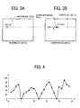
- FIG. 3A is a conceptual diagram illustrating a reference pixel in a reference image
- FIG. 3B is a conceptual diagram for explaining calculating the cost by successively shifting candidate corresponding pixels in a comparison image relative to the reference pixel shown in FIG. 3A
- FIG. 4 is a graph of a cost profile plotting costs with respect to shift values.
- the corresponding pixel is a pixel in the comparison image that is the most similar, for example, in luminance value to the reference pixel in the reference image.
- C(p,d) is equivalent to C(x,y,d), as p represents (x, y).
- a reference pixel p(x,y) is set in the reference image.
- a plurality of candidate corresponding pixels q(x+d,y) that may correspond to the reference pixel p(x,y) are set on the epipolar line EL in the comparison image, wherein the epipolar line EL is set in the reference image and the comparison image as illustrated in FIGs. 3A and 3B .
- the cost C(p,d) of each of the candidate corresponding pixels q(x+d,y) with respect to the reference pixel p(x,y) is calculated.
- "d" corresponds to a shift value of each of the candidate corresponding pixels "q" with respect to the reference pixel "p,” and the shift value "d” is expressed, for example, in units of pixels. That is, in the example case of FIG. 3 (FIGs.
- the cost C(p,d) which indicates a level of dissimilarity between luminance of the candidate corresponding pixels q(x+d,y) and luminance of the reference pixel p(x,y), is calculated by successively shifting the candidate corresponding pixels q(x+d,y) one pixel by one pixel in a pre-set range or region (e.g., 0 ⁇ d ⁇ 25).
- the cost C can be calculated by applying any known method such as SAD (Sum of Absolute Difference) when the cost C represents a level of dissimilarity.
- the calculated costs C(p,d) can be expressed as a cost profile by plotting the calculated costs C with respect to the shift values "d."
- FIG. 5 is a conceptual diagram for describing calculation of the synthesis cost Ls.
- FIG. 6 is a graph of a synthesis cost profile plotting synthesis costs with respect to disparity values.
- the synthesis cost Ls(p,d) is obtained by calculating the cost C(p,d) for one reference pixel p(x,y), by calculating cost C for other pixels p'(x',y') used as other reference pixels existing at positions surrounding the one reference pixel p(x,y) such as from near to far positions with respect to the reference pixel p(x,y), and by aggregating or converging the cost C(p,d) for the one reference pixel p(x,y) and the costs C for other reference pixels p'(x',y') as the synthesis cost Ls(p,d).
- Equation (3) is used for calculating the directional path cost Lr(p,d)
- equation (4) is used for calculating the synthesis cost Ls.
- Lr p ⁇ d C p ⁇ d + min ( Lr ⁇ p - r , d , Lr ⁇ p - r , d - 1 + P ⁇ 1 , Lr ⁇ p - r , d + 1 + P ⁇ 1 , Lrmin ⁇ p - r + P ⁇ 2
- Lr indicates a direction vector along the aggregated direction having two directional components such as the x direction component and the y direction component.
- min ⁇ is a function for obtaining the minimum value.
- Lrmin(p-r) indicates the minimum value of Lr(p-r,d) when the shift value "d" is changed in the coordinates where "p" is shifted by one pixel in "r” direction. It should be noted that Lr is recurrently applied as expressed in the equation (3).
- Lr(p,d) for the reference pixel p(x,y) can be obtained by adding the minimum value of the directional path cost Lr of pixels existing along "r" direction from the reference pixel p(x,y) illustrated in FIG. 5 to the cost C of the reference pixel p(x,y).
- Lr is obtained for each one of pixels existing along "r" direction one by one starting from the farthest end pixel, which is the farthest from the reference pixel p(x,y). Based on the Lr obtained for the pixels existing along "r” direction, the Lr(p,d) of the pixel p(x,y) along "r" direction can be obtained.
- a plurality of directional path costs Lr can be obtained along a plurality of directions.
- a plurality of directional path costs such as Lr 0 , Lr 45 , Lr 90 , Lr 135 , Lr 180 , Lr 225 , Lr 270 , Lr 315 is obtained in eight directions.
- the synthesis cost Ls is finally obtained by applying the equation (4) to the plurality of directional path costs Lr.
- L s p ⁇ d ⁇ 8 Lr
- the calculated synthesis costs Ls(p,d) can be expressed as a graph of a synthesis cost profile by plotting the synthesis costs Ls(p,d) with respect to the shift values "d" as illustrated in FIG. 6 .
- “r” is set to eight in the above description, “r” is not limited hereto.
- the eight directions can be further divided into sixteen directions (two times of eight directions), twenty four directions (three times of eight directions), and so on.
- the synthesis cost Ls is calculated by applying the equation (4) that totals the directional path costs Lr for all of the directional paths "r" calculated by the equation (3), but the synthesis cost Ls is not limited hereto.
- the directional path cost Lr in a single directional path can be used as the synthesis cost Ls, or the directional path costs Lr in two or more directional paths can be synthesized as the synthesis cost Ls.
- the cost C is used as an indicator of "dissimilarity” in the above description, the cost C can be used as an indicator of "similarity” that is the opposite of “dissimilarity.”
- a known method such as Normalized Cross Correlation (NCC) can be used as the method of calculating the cost C, in which the disparity value ⁇ at which the synthesis cost Ls becomes the "maximum” is derived instead of using the disparity value ⁇ at which the synthesis cost Ls becomes the "minimum.”
- NCC Normalized Cross Correlation
- the similarity and dissimilarity may be collectively referred to as "matching level" of the cost.
- an object recognition system 1 mounted on a vehicle such as an automobile is described as one example.
- the object recognition system 1 is mountable on vehicles such as motor bicycles, bicycles, wheelchairs, agricultural tractors, construction machines, or the like.
- the object recognition system 1 is mountable on vehicles, which is an example of movable apparatuses, and also on robots, which is another example of movable apparatuses.
- the robots are not limited to the movable apparatuses but can be fixed apparatuses such as industrial robots fixed at a given place such as robots for factory automation (FA).
- the fixed apparatuses may not be limited to the robots, but can be other apparatuses such as security monitoring cameras or the like.
- FIG. 7A is a schematic side view of a vehicle 100 such as an automobile mounting the object recognition system 1
- FIG. 7B is a schematic front view of the vehicle 100 of FIG. 7A
- FIG. 8 is a schematic perspective view of the object recognition system 1.
- the object recognition system 1 includes, for example, an imaging device 10a and an imaging device 10b.
- the imaging device 10a and the imaging device 10b can be disposed at least at one position to capture images of scenes ahead of the vehicle 100.
- the object recognition system 1 includes, for example, a main body 2 and a pair of the imaging device 10a and imaging device 10b, shaped into a cylindrical shape, provided on the main body 2.
- the object recognition system 1 is disposed at the position shown in FIG. 7 , the position to dispose the object recognition system 1 is not limited hereto.
- the object recognition system 1 can be disposed at any position on the apparatus depending on fields of application of the apparatus.
- FIG. 9 is a block diagram example of a hardware configuration of the object recognition system 1.
- the object recognition system 1 includes, for example, a disparity deriving apparatus 3, and an object recognition apparatus 5 in the main body 2.
- the disparity deriving apparatus 3 derives a disparity value ⁇ indicating disparity of the object E based on a plurality of images obtained by imaging the object E, and outputs a high density disparity image indicating the disparity value ⁇ for each pixel in the images.
- the object recognition apparatus 5 performs processing such as range-finding between the imaging devices 10a/10b and the object E based on a high density disparity image output from the disparity deriving apparatus 3.
- the disparity deriving apparatus 3 includes, for example, the imaging device 10a, the imaging device 10b, a signal conversion device 20a, a signal conversion device 20b, and an image processing device 30.
- the imaging device 10a includes, for example, an imaging lens 11a, an aperture 12a, and an image sensor 13a to generate an analog signal for reproducing an image by capturing images of scenes ahead of the vehicle 100 ( FIG. 7 ).
- the imaging lens 11a is an optical element for diffracting light passing through the imaging lens 11a to form an image of an object on the image sensor 13a.
- the aperture 12a cuts off a part of the light passing through the imaging lens 11 a to adjust the quantity of light input to the image sensor 13a to be described later.
- the image sensor 13a is, for example, a semiconductor device that converts the light input from the imaging lens 11a and the aperture 12a into an electrical analog image signal, and can be implemented, for example, as a charge coupled device (CCD) or a complementary metal oxide semiconductor (CMOS).
- the imaging device 10b has the same configuration as the imaging device 10a, and thereby a description of the imaging device 10b is omitted.
- the imaging lens 11a and the imaging lens 11b are installed such that their respective lens faces are on the same plane.
- the signal conversion device 20a includes, for example, a correlated double sampling (CDS) 21a, an auto gain control (AGC) 22a, an analog digital converter (ADC) 23a, and a frame memory 24a to convert the analog signal for reproducing the captured image into image data in digital format.
- the CDS 21 a removes noise from the analog image signal converted by the image sensor 13a by conducting correlated double sampling.
- the AGC 22a performs gain control for controlling the intensity of the analog image signal removed with the noise by the CDS 21a.
- the ADC 23a converts the analog image signal, gain-controlled by the AGC 22a, into image data in digital format.
- the frame memory 24a stores the image data converted by the ADC 23a.
- the signal conversion device 20b includes a CDS 21b, an AGC 22b, an ADC 23b, and a frame memory 24b to convert the analog image signal input from the imaging device 10b.
- the CDS 21b, AGC 22b, ADC 23b, and frame memory 24b respectively have the same configuration as the CDS 21 a, AGC 22a, ADC 23 a, and frame memory 24a, and thereby a description thereof is omitted.
- the image processing device 30 is a device for processing the image data converted by the signal conversion device 20a and the signal conversion device 20b.
- the image processing device 30 includes, for example, a field programmable gate array (FPGA) 31, a central processing unit (CPU) 32, a read only memory (ROM) 33, a random access memory (RAM) 34, an interface (I/F) 35, and a bus line 39 such as an address bus and a data bus for electrically connecting the components 31 to 35 as illustrated in FIG. 9 .
- FPGA field programmable gate array
- CPU central processing unit
- ROM read only memory
- RAM random access memory
- I/F interface
- bus line 39 such as an address bus and a data bus for electrically connecting the components 31 to 35 as illustrated in FIG. 9 .
- the FPGA 31 is an integrated circuit that performs the process of calculating a disparity value ⁇ in the image represented by image data based on an instruction from the CPU 32.
- the CPU 32 controls entire operation performed by the disparity deriving apparatus 3.
- the ROM 33 stores an image processing program executable by the CPU 32 to control entire operation performed by the disparity deriving apparatus 3.
- the RAM 34 is used as a working area for the CPU 32.
- the I/F 35 is an interface for communicating with an I/F 55 of the object recognition apparatus 5, to be described later, through the bus line 4 such as an address bus and a data bus.
- the object recognition apparatus 5 includes, for example, an FPGA 51, a CPU 52, a ROM 53, a RAM 54, an I/F 55, a controller area network (CAN) I/F 58, and a bus line 59 such as an address bus and a data bus for electrically connecting the components 51 to 55 and 58 as illustrated in FIG. 9 .
- a bus line 59 such as an address bus and a data bus for electrically connecting the components 51 to 55 and 58 as illustrated in FIG. 9 .
- the FPGA 51, CPU 52, ROM 53, RAM 54, I/F 55, and bus line 59 respectively have the same configuration as the FPGA 31, CPU 32, ROM 33, RAM 34, I/F 35, and bus line 39 in the image processing device 30, and thereby a description thereof is omitted.
- the I/F 55 is an interface for communicating with the I/F 35 of the image processing device 30 through the bus line 4.
- the ROM 53 stores an object recognition program executable by the CPU 52 to control entire operation performed by the object recognition apparatus 5.
- the CAN I/F 58 is an interface for communicating with an external controller or the like, and can be connected to, for example, a controller area network (CAN) of automobiles.
- CAN controller area network
- the FPGA 51 calculates the distance Z between the imaging devices 10a/10b and the object E based on an instruction from the CPU 52 in the object recognition apparatus 5. Further, the FPGA 31 can calculate the distance Z under an instruction from the CPU 32 of the image processing device 30 instead of calculating the distance Z by the FPGA 51 under an instruction from the CPU 52 in the object recognition apparatus 5.
- the two imaging devices 10a and 10b are used but not limited hereto.
- one imaging device can be used, in which an imaging area is separated into two areas on one image sensor to capture the reference image and the comparison image of the object E.
- the above described programs may be stored in a computer-readable storage medium or carrier medium with an installable or executable file format for distribution of programs.
- the storage medium or carrier medium is, for example, a compact disc read only memory (CD-ROM), a secure digital (SD) memory card or the like, but not limited thereto.
- the directional path cost Lr(p,d) for the reference pixel p(x,y) can be obtained as illustrated in FIG. 10 . Specifically, at first, the directional path cost Lr(p-nr,d) is calculated for a pixel at a position, which is the farthest from the reference pixel p(x,y), by applying the equation (3).
- the directional path cost Lr(p-(n-1)r,d) is calculated at a next pixel on the same "r" direction and at a position closer to the reference pixel p(x,y) by applying the equation (3) using the calculated directional path cost Lr(p-nr,d).
- the directional path cost Lr is calculated at a further next pixel on the same "r" direction and at a position further closer to the reference pixel p(x,y) by applying the equation (3) using the calculated directional path cost Lr(p-(n-1)r,d).
- This calculation process using the previous calculation result is repeated for each one of pixels on the same "r" direction to calculate the directional path cost Lr(p,d) for the reference pixel p(x,y) finally.
- the equation (3) is used to derive the directional path cost Lr(p,d) based on the cost C(p,d) and the directional path cost Lr(p-r,d). Since the directional path cost Lr is derived from the cost C(p,d), it can be understood that the equation (3) is derived from the cost C(p,d) and the cost C(p-nr,d).
- FIG. 11 is a schematic hardware configuration of the main part of the disparity deriving apparatus 3, which corresponds to functional units of the FPGA 31 ( FIG. 9 ).
- the FPGA 31 ( FIG. 9 ) includes, for example, a cost calculator 310 as a calculator, a cost synthesizer 320 as a synthesizer, and a disparity value deriving unit 330 as a deriving unit. Although these units are part of the circuitry of the FPGA 31, processing that can be performed by these units can be performed by executing the above mentioned program.
- the cost calculator 310 calculates and outputs the costs C of candidate corresponding pixels q(x+d,y) in the comparison image ( FIG. 3B ) with respect to a corresponding reference pixel p(x,y) in a reference image ( FIG. 3A ).
- the cost calculator 310 calculates and outputs the costs C of the candidate corresponding pixels q(x+d,y) in the comparison image, which may correspond to the reference pixel p(x,y) in the reference image, based on a difference of luminance of the reference pixel p(x,y) in the reference image and luminance of the candidate corresponding pixels q(x+d,y) in the comparison image by shifting positions of the candidate corresponding pixels, identified by corresponding shift values d, on the epipolar line EL extended from the reference pixel p(x,y) in the reference image to the comparison image. Further, the cost calculator 310 can be configured to retain or store each of the calculated costs C in a memory.
- the cost synthesizer 320 For each of the shift values "d," the cost synthesizer 320 synthesizes the costs C of candidate corresponding pixels q(x+d,y) corresponding to one reference pixel p(x,y) output by the cost calculator 310, and the costs C of candidate corresponding pixels q'(x'+d,y') corresponding to other reference pixel p'(x',y') output by the cost calculator 310, and outputs the synthesized costs as the synthesis cost Ls.
- the synthesizing process is conducted by calculating the directional path costs Lr' based on the costs C using the equation (3'), instead of the equation (3), and then adding the directional path costs Lr' for each of the directions using the equation (4') to calculate the synthesis cost Ls' finally.
- Lr ⁇ p ⁇ d C p ⁇ d + Ad x min ( Lr ⁇ p - r , d , Lr ⁇ p - r , d - 1 + P ⁇ 1 , Lr ⁇ p - r , d + 1 + P ⁇ 1 , Lrmin ⁇ p - r + P ⁇ 2 0 ⁇ Ad ⁇ 1
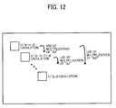
- the cost synthesizer 320 synthesizes the costs C of each of candidate corresponding pixels with respect to a first reference pixel multiplied by a first weight, and the costs C of each of candidate corresponding pixels with respect to a second reference pixel multiplied by a second weight, wherein the second weight (e.g., multiplication of 0.9) is smaller than the first weight (e.g., multiplication of one), to calculate the directional path cost Lr' for a directional path "r" on the reference image, and then totals the directional path costs Lr' for each of the directional paths "r" to calculate the synthesis cost Ls' for each of the shift values.
- the second weight e.g., multiplication of 0.9
- the first weight e.g., multiplication of one
- the cost synthesizer 320 synthesizes the cost C of the first reference pixel multiplied by the first weight, the cost C of the second reference pixel multiplied by the second weight, and a cost C of a third reference pixel multiplied by a third weight, in which the third weight (e.g., multiplication of 0.81) is smaller than the second weight (e.g., multiplication of 0.9), and a distance of the third reference pixel from the first reference pixel is far compared to a distance of the second reference pixel from the first reference pixel on the directional path where the first and second reference pixels exist in the reference image.
- the third weight e.g., multiplication of 0.81
- the second weight e.g., multiplication of 0.9
- the computation load can be reduced.
- a coefficient of synthesis level such as weight coefficient "Ad”
- the number of multiplying times of the weight coefficient "Ad" for the recurrent computing becomes greater as pixels are farther from the first reference pixel on the directional path.
- the synthesis level can be reduced as pixels are farther from the first reference pixel on the directional path by using the recurrent computing.
- a calculation using the equation (3') is conducted to pixels along one or more directional paths extending from the reference pixel p(x,y) to obtain the directional path cost Lr'(p,d) for the reference pixel p(x,y).
- a calculation using the equation (3') is conducted at a pixel (first pixel) farthest from the reference pixel p(x,y) to calculate the directional path cost Lr'(p-nr,d).
- equation (4') is applied to calculate the synthesis cost Ls' instead of the equation (4).
- Ls ⁇ p ⁇ d ⁇ Lr ⁇
- the disparity value deriving unit 330 derives a shift value "d" corresponding to the smallest synthesis cost Ls, output by the cost synthesizer 320, as the disparity value ⁇ .
- the weight coefficient Ad can be stored in the RAM 34, and a value of the weight coefficient Ad can be changed by an input operation by a user, in which a value of the weight coefficient Ad can be set differently for each of the directional paths "r" shown in FIG. 5 .
- the weight coefficient Ad set for each of the directional paths "r" can be changed for each frame data of an image captured by the imaging devices 10a and 10b.
- the equation (3') is applied only to the directional paths of r 0 and r 180
- the equation (3) is applied to other directional paths.
- the equation (3') is applied only to the directional paths r 90 and r 270 , and the equation (3) is applied for other directional paths.
- FIGs. 13 to 16 an operation according to the one or more example embodiments is described. Specifically, a method of deriving the disparity value ⁇ is described with reference to FIGs. 13 to 16 .
- FIG. 13 is a flowchart showing the steps of a process of disparity computation according to one example embodiment.
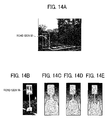
- FIG. 14A is an example of a reference image.
- FIG. 14B is a part of the reference image of FIG. 14A.
- FIG. 14B is a high density disparity image generated by applying the equation (3) to the reference image of FIG. 14B.
- FIG. 14D is a high density disparity image generated by applying the equation (3') to the reference image of FIG. 14B.
- FIG. 14E is another high density disparity image generated by applying the equation (3') to the reference image of FIG. 14B .
- FIG. 15 is a schematic view of a reference image, which is expanded partially.
- FIG. 16 illustrates examples of cost profiles with respect shift values, and an example of a synthesis cost profile with respect shift values in the reference image of FIG. 15 .
- the imaging device 10a ( FIG. 9 ) generates analog image data by capturing an image of the object E (step S1-1).
- the imaging device 10b generates analog image data by capturing an image of the object E (step S1-2).
- the signal conversion device 20a converts the analog image data into digital image data (step S2-1).
- the signal conversion device 20b converts the analog image data into digital image data (step S2-2).
- the signal conversion device 20a outputs the digital image data, converted at step S2-1, to the FPGA 31 of the image processing device 30 as data of a reference image (step S3-1), wherein an example of the reference image is shown in FIG. 2A .
- the signal conversion device 20b outputs the digital image data, converted at step S2-2, to the FPGA 31 of the image processing device 30 as data of a comparison image (step S3-2). Since the comparison image, which is the image captured by the imaging device 10b, has no significant difference from the reference image shown in FIG. 2A , an example view of the comparison image is omitted.
- the cost calculator 310 calculates the costs C for each one of the shift values "d" based on the data of the reference image and the data of the comparison image (step S4).
- the cost synthesizer 320 calculates the directional path cost Lr' by applying the equation (3') (step S5). Further, the cost synthesizer 320 calculates the synthesis cost Ls' by applying the equation (4') (step S6).
- the synthesis cost Ls is calculated at a position of the pixel "p" by applying the equations (3) and (4) in the case illustrated in FIG. 15 , even if the position of the pixel (p-nr) is far from the position of pixel "p," the very small cost C affects other costs C, with which, for example, the high density disparity image shown in FIG. 14C is generated.
- the high density disparity image shown in FIG. 14D can express an image having a shape or contour closer to a real object compared to the high density disparity image shown in FIG. 14C .
- the above mentioned very small cost C corresponds to a cost of strong texture.
- FIG. 14E illustrates a high density disparity image when the weight coefficient Ad is 0.9
- FIG. 14E illustrates a high density disparity image when the weight coefficient Ad is 0.8. Therefore, the smaller the weight coefficient Ad, the closer the high density disparity image to the real object. In this example case of FIG. 14 , the shape of the object in the image becomes smaller and sharp.
- the weight coefficient Ad is set further smaller such as less than a given value (e.g., 0.7), a difference between the minimum value of Ls and a local minimum value (i.e., other than the minimum value of Ls) in the synthesis cost profile shown in FIG. 16 becomes too small, with which reliability of the derived disparity value ⁇ becomes lower.
- the disparity value deriving unit 330 derives the shift value "d" corresponding to the smallest synthesis cost Ls' output by the cost synthesizer 320 as the disparity value ⁇ (step S7). Then, the disparity value deriving unit 330 derives the disparity value ⁇ for all pixels, and outputs the disparity value ⁇ of all pixels finally.
- the disparity image can be changed from the high density disparity image of FIG. 14D to the high density disparity image of FIG. 14E , which is further closer to the shape of a real object.
- the cost C is used as an indicator of "dissimilarity” in the above description, the cost C can be used as an indicator of "similarity” that is the opposite of “dissimilarity.”
- the disparity value ⁇ at which the cost C becomes the "maximum” is derived instead of using the disparity value ⁇ at which the cost C becomes the "minimum”
- the disparity value ⁇ at which the synthesis cost Ls becomes the “maximum” is derived instead of using the disparity value ⁇ at which the synthesis cost Ls becomes the "minimum.”
- the similarity and dissimilarity may be collectively referred to as "matching level" of the cost.
- the coefficient of C(p,d) is set “1,” and the coefficient of min ⁇ is set “Ad,” but not limited hereto.
- the coefficient of C(p,d) can be set “Ad1,” and the coefficient of min ⁇ can be set “Ad2" with conditions of "Ad1 ⁇ Ad2, 0 ⁇ Ad1, 0 ⁇ Ad2.
- the coefficients "Ad1” and “Ad2" can be within a range of "1 ⁇ Ad1 ⁇ Ad2,” in which the above described first weight, second weight, and third weight can be set one or more (i.e., 100% or more).
- the above described example embodiments include at least following configurations.
- the disparity deriving apparatus can derive disparity of an object using a reference image of the object captured by a first imaging device, and a comparison image of the object captured by a second imaging device, in which the disparity is indicated by a disparity value.
- the disparity deriving apparatus includes a calculator such as the cost calculator 310, a synthesizer such as the cost synthesizer 320, and a deriving unit such as the disparity value deriving unit 330.
- the imaging device 10a is one example of the first imaging device
- the imaging device 10b is one example of the second imaging device.
- the calculator calculates the costs between the reference image and the comparison image by computing a difference of luminance of a reference area (e.g., pixel) in the reference image, and luminance of each one of candidate corresponding areas (e.g., pixel) in the comparison image, corresponding to the reference area, by shifting positions of the candidate corresponding areas on the epipolar line EL in the comparison image, wherein the epipolar line EL is extended from the reference area in the reference image, in which the positions of the candidate corresponding areas can be identified based on the corresponding shift value, and the cost represents a level of dissimilarity or a level of similarity between luminance of the reference area and luminance of the candidate corresponding areas.
- the calculator calculate costs between a first reference area in the reference image and each one of corresponding areas corresponding to the first reference area in a given region in the comparison image, and costs between a second reference area, surrounding the first reference area in the reference image, and each one of corresponding areas corresponding to the second reference area in a given region in the comparison image.
- the synthesizer synthesizes the costs of the first reference area multiplied by the first weight, wherein the costs are calculated by the calculator, and the costs of the second reference area multiplied by the second weight smaller than the first weight, wherein the costs are calculated by the calculator, to calculate the directional path cost for one or more directional paths on the reference image, and then totals the directional path costs for each of the directional paths to calculate the synthesis costs for each of the shift values.
- the deriving unit derives a disparity value of an object captured on the first reference area based on the synthesis costs synthesized by the synthesizer.
- the synthesizer synthesizes the costs of the first reference area multiplied by the first weight, the costs of the second reference area multiplied by the second weight smaller than the first weight, and costs of a third reference area multiplied by a third weight smaller than the second weight, as the synthesis costs, wherein a distance of the third reference area from the first reference area is far compared to a distance of the second reference area from the first reference area on the directional path including the first reference area and the second reference area.
- the synthesizer synthesizes the costs of the first reference area multiplied by the first weight, and the costs of the second reference multiplied by the second weight to calculate the directional path cost on the one or more directional paths on the reference image.
- disparity detection can be performed with high precision.
- the present invention can be implemented in any convenient form, for example using dedicated hardware, or a mixture of dedicated hardware and software.
- the computer software can be provided to the programmable device using any storage medium or carrier medium for storing processor-readable code such as a floppy disk, a compact disk read only memory (CD-ROM), a compact disk rewritable (CD-RW), a digital versatile disk read only memory (DVD-ROM), DVD recording only/rewritable (DVD-R/RW), electrically erasable and programmable read only memory (EEPROM), erasable programmable read only memory (EPROM), a memory card or stick such as USB memory, a memory chip, a mini disk (MD), a magneto optical disc (MO), magnetic tape, a hard disk in a server, a solid state memory device or the like, but not limited these.
- processor-readable code such as a floppy disk, a compact disk read only memory (CD-ROM), a compact disk rewritable (CD-
- the carrier medium can compromise a transient carrier medium such as an electrical, optical, microwave, acoustic or radio frequency signal carrying the computer code.
- a transient carrier medium such as an electrical, optical, microwave, acoustic or radio frequency signal carrying the computer code.
- An example of such a transient medium is a TCP/IP signal carrying computer code over an IP network, such as the Internet.
- the carrier medium can also comprise a storage medium for storing processor readable code such as a floppy disk, hard disk, CD ROM, magnetic tape device or solid state memory device.
- the computer software can be provided from a transmitting apparatus, which transmits signals, via a transmission medium such as public phone line, dedicated line, or other communication line, in which a part of the computer software is transmitted on the transmission medium, which means it is not required to transmit the entire data of the computer software is being transmitted on the transmission medium at one time.
- the signals includes data signals of the computer software and other data.
- the transmitting apparatus can transmit the computer software by transmitting data of the computer software continuously or intermittently.
- the hardware platform includes any desired kind of hardware resources including, for example, a central processing unit (CPU), a random access memory (RAM), and a hard disk drive (HDD).
- the CPU may be implemented by any desired kind of any desired number of processors.
- the RAM may be implemented by any desired kind of volatile or non-volatile memory.
- the HDD may be implemented by any desired kind of non-volatile memory capable of storing a large amount of data.
- the hardware resources may additionally include an input device, an output device, or a network device, depending on the type of apparatus. Alternatively, the HDD may be provided outside of the apparatus as long as the HDD is accessible.
- the CPU such as a cache memory of the CPU
- the RAM may function as a physical memory or a primary memory of the apparatus, while the HDD may function as a secondary memory of the apparatus.
- a computer can be used with a computer-readable program, described by object-oriented programming languages such as C++, Java (registered trademark), JavaScript (registered trademark), Perl, Ruby, or legacy programming languages such as machine language, assembler language to control functional units used for the apparatus or system.
- object-oriented programming languages such as C++, Java (registered trademark), JavaScript (registered trademark), Perl, Ruby, or legacy programming languages such as machine language, assembler language to control functional units used for the apparatus or system.
- a particular computer e.g., personal computer, workstation
- At least one or more of the units of apparatus can be implemented as hardware or as a combination of hardware/software combination.
- Each of the functions of the described embodiments may be implemented by one or more processing circuits.
- a processing circuit includes a programmed processor, as a processor includes circuitry.
- a processing circuit also includes devices such as an application specific integrated circuit (ASIC) and conventional circuit components arranged to perform the recited functions.
- ASIC application specific integrated circuit
Landscapes
- Engineering & Computer Science (AREA)
- Computer Vision & Pattern Recognition (AREA)
- Physics & Mathematics (AREA)
- General Physics & Mathematics (AREA)
- Theoretical Computer Science (AREA)
- Image Processing (AREA)
- Image Analysis (AREA)
- Manipulator (AREA)
Abstract
Description
- The present invention relates to deriving disparity of an object based on a reference image and a comparison image each obtained by capturing an image of the same object.
- A range-finding method using disparity information is conventionally known, in which disparity of an object observed by a stereo camera is derived by stereo imaging, and a disparity value indicating this disparity is used to measure the distance from the stereo camera to the object based on the principle of triangulation. With this range-finding method, for example, the distance between two automobiles or between an automobile and obstacles can be measured and utilized for preventing automobile collisions. The range-finding method may be also referred to as the distance measurement method.
- Specifically, a stereo matching process is employed for deriving disparity. In the stereo matching process, a reference image is captured by one camera of a stereo camera, composed of two cameras, and a comparison image is captured by the other camera of the stereo camera. Then, by successively shifting a plurality of candidate corresponding pixels in the comparison image relative to one reference pixel set in the reference image, a position of a corresponding pixel having an image signal that is the most similar to an image signal of the reference pixel set in the reference image is identified to derive a disparity value between the reference image and the comparison image. Typically, luminance values of image signals obtained by the two cameras are compared to compute "cost" (hereinafter, cost means "dissimilarity") of the compared luminance values, with which a position of a pixel having the smallest cost is identified. Further, the stereo matching process can employ a block matching process to prevent mismatching, in which luminance at edges in an image where luminance changes greatly are compared as disclosed in
JP-2006-090896-A - However, for areas having weak texture (i.e., an area where the magnitude of luminance change of an object is weak) and the features to be extracted are themselves diminished, edge detection may not be effective.
- In view of this ineffective edge detection, a method that derives more accurate disparity for an object having weak texture is proposed as disclosed in
JP-2012-181142-A - When the method disclosed in
JP-2012-181142-A - In one aspect of the present invention, a disparity deriving apparatus for deriving disparity of an object based on a reference image of the object captured at a first image capturing position and a comparison image of the object captured at a second image capturing position is devised. The disparity deriving apparatus includes a calculator to calculate costs between a first reference area in the reference image and each one of corresponding areas corresponding to the first reference area in a given region in the comparison image, and costs between a second reference area, surrounding the first reference area in the reference image, and each one of corresponding areas corresponding to the second reference area in a given region in the comparison image; a synthesizer to synthesize the costs of the first reference area multiplied by a first weight, the costs calculated by the calculator, and the costs of the second reference area multiplied by a second weight smaller than the first weight, the cost calculated by the calculator, as synthesis costs; and a deriving unit to derive a disparity value of an object captured on the first reference area based on the synthesis costs synthesized by the synthesizer.
- In another aspect of the present invention, a method of deriving disparity of an object based on a reference image of the object captured at a first image capturing position and a comparison image of the object captured at a second image capturing position is devised. The method includes the steps of calculating costs between a first reference area in the reference image and each one of corresponding areas corresponding to the first reference area in a given region in the comparison image, and costs between a second reference area, surrounding the first reference area in the reference image, and each one of corresponding areas corresponding to the second reference area in a given region in the comparison image; synthesizing the costs of a first reference area multiplied by a first weight, the costs calculated by the calculating step, and the cost of the second reference area multiplied by a second weight smaller than the first weight, the cost calculated by the calculating step, as synthesis costs; and deriving a disparity value of an object captured on the first reference area based on the synthesis costs synthesized by the synthesizing step. In another aspect of the present invention, a method of producing disparity of an object based on a reference image of the object captured at a first image capturing position and a comparison image of the object captured at a second image capturing position is devised. The method includes the steps of calculating costs between a first reference area in the reference image and each one of corresponding areas corresponding to the first reference area in a given region in the comparison image, and costs between a second reference area, surrounding the first reference area in the reference image, and each one of corresponding areas corresponding to the second reference area in a given region in the comparison image; synthesizing the costs of a first reference area multiplied by a first weight, the costs calculated by the calculating step, and the cost of the second reference area multiplied by a second weight smaller than the first weight, the cost calculated by the calculating step, as synthesis costs; and deriving a disparity value of an object captured on the first reference area based on the synthesis costs synthesized by the synthesizing step. In another aspect of the present invention, a non-transitory computer-readable carrier medium storing a program that, when executed by a computer, causes the computer to execute a method of deriving disparity of an object based on a reference image of the object captured at a first image capturing position and a comparison image of the object captured at a second image capturing position is devised. The method includes the steps of calculating costs between a first reference area in the reference image and each one of corresponding areas corresponding to the first reference area in a given region in the comparison image, and costs between a second reference area, surrounding the first reference area in the reference image, and each one of corresponding areas corresponding to the second reference area in a given region in the comparison image; synthesizing the costs of a first reference area multiplied by a first weight, the costs calculated by the calculating step, and the cost of the second reference area multiplied by a second weight smaller than the first weight, the cost calculated by the calculating step, as synthesis costs; and deriving a disparity value of an object captured on the first reference area based on the synthesis costs synthesized by the synthesizing step.
- In another aspect of the present invention, a disparity deriving apparatus for deriving disparity of an object based on a reference image of the object captured at a first image capturing position and a comparison image of the object captured at a second image capturing position is devised. The disparity deriving apparatus includes a calculator to calculate matching level between a first reference area in the reference image and each one of corresponding areas corresponding to the reference first area in a given region in the comparison image, and matching level between a second reference area, surrounding the first reference area in the reference image, and each one of corresponding areas corresponding to the second reference area in a given region in the comparison image; a synthesizer to synthesize the matching level of the first reference area, the matching level calculated by the calculator, and the matching level of the second reference area multiplied by a weight, the matching level calculated by the calculator, as synthesis matching level; and a deriving unit to derive a disparity value of the object captured at the first reference area based on the synthesis matching level synthesized by the synthesizer, and to output the derived disparity value to an object recognition apparatus useable for recognizing the object in the reference image or the comparison image. An image area corresponding to the object, expressed by the disparity value derived by the deriving unit and recognizable by the object recognition apparatus, becomes smaller as the weight becomes smaller.
- As to the above described one or more aspects of the present invention, even if an object having weak texture and an object having strong texture exist in the same scene, an effect of the disparity at the strong-texture object to disparity at the weak-texture object can be reduced. Therefore, disparity detection can be performed with high precision.
- A more complete appreciation of the disclosure and many of the attendant advantages and features thereof can be readily obtained and understood from the following detailed description with reference to the accompanying drawings, wherein:
-
FIG. 1 illustrates the principle of computing the distance from an imaging device to an object; -
FIG. 2A is an example of a reference image; -
FIG. 2B is an example of a high density disparity image generated from the reference image ofFIG. 2A ; -
FIG. 2C is an example of an edge disparity image generated from the reference image ofFIG. 2A ; -
FIG. 3A is a conceptual diagram illustrating a reference pixel in a reference image; -
FIG. 3B is a conceptual diagram for explaining calculating cost by successively shifting candidate corresponding pixels in a comparison image relative to the reference pixel shown inFIG. 3A ; -
FIG. 4 is a graph of a cost profile plotting costs with respect to shift values; -
FIG. 5 is a conceptual diagram for explaining deriving a synthesis cost; -
FIG. 6 is a graph of a synthesis cost profile plotting synthesis costs with respect to disparity values; -
FIG. 7A is a schematic side view of a vehicle mounting an object recognition system according to one or more example embodiments; -
FIG. 7B is a schematic front view of the vehicle ofFIG. 7A ; -
FIG. 8 is a schematic perspective view of the object recognition system ofFIG. 7A ; -
FIG. 9 is a block diagram example of hardware configuration of the object recognition system ofFIG. 7 ; -
FIG. 10 is a conceptual diagram for explaining deriving directional path cost on a reference image; -
FIG. 11 is a schematic diagram illustrating a hardware configuration of a main part of a disparity deriving apparatus; -
FIG. 12 is a conceptual diagram or explaining deriving synthesis cost; -
FIG. 13 is a flowchart illustrating operation of disparity computation according to one or more example embodiments; -
FIG. 14A is an example of a reference image; -
FIG. 14B is a part of the reference image ofFIG. 14A ; -
FIG. 14C is a high density disparity image generated by applying equation (3) to the reference image ofFIG. 14B ; -
FIG. 14D is a high density disparity image generated by applying equation (3') to the reference image ofFIG. 14B ; -
FIG. 14E is another high density disparity image generated by applying equation (3') to the reference image ofFIG. 14B ; -
FIG. 15 is a schematic view of a reference image, which is expanded partially; and -
FIG. 16 illustrates examples of cost profiles with respect shift values and an example of a synthesis cost profile with respect shift values on the reference image ofFIG. 15 . - A description is now given of exemplary embodiments of the present invention. It should be noted that although such terms as first, second, etc. may be used herein to describe various elements, components, regions, layers and/or sections, it should be understood that such elements, components, regions, layers and/or sections are not limited thereby because such terms are relative, that is, used only to distinguish one element, component, region, layer or section from another region, layer or section. Thus, for example, a first element, component, region, layer or section discussed below could be termed a second element, component, region, layer or section without departing from the teachings of the present invention.
- In addition, it should be noted that the terminology used herein is for the purpose of describing particular embodiments only and is not intended to be limiting of the present invention. Thus, for example, as used herein, the singular forms "a", "an" and "the" are intended to include the plural forms as well, unless the context clearly indicates otherwise. Moreover, the terms "includes" and/or "including", when used in this specification, specify the presence of stated features, integers, steps, operations, elements, and/or components, but do not preclude the presence or addition of one or more other features, integers, steps, operations, elements, components, and/or groups thereof.
- Furthermore, although in describing views shown in the drawings, specific terminology is employed for the sake of clarity, the present disclosure is not limited to the specific terminology so selected and it is to be understood that each specific element includes all technical equivalents that operate in a similar manner and achieve a similar result. Referring now to the drawings, an apparatus or system according to one or more example embodiments are described hereinafter.
- Referring to
FIGs. 1 to 6 , a description is given of a range-finding method using semi-global matching (SGM). Since SGM is disclosed in "Accurate and Efficient Stereo Processing by Semi-Global Matching and Mutual Information" (author: Hirschmuller, H. Inst. of Robotics & Mechatronics Oberpfaffenhofen, German Aerosp. Center, Wessling, Germany), only a brief explanation of SGM is given below. - Referring to
FIG. 1 , a description is given of the principle of measuring distance from a stereo camera to an object, in which disparity of the object is derived as a disparity value by conducting stereo imaging using the stereo camera, and the derived disparity value is used to measure the distance from the stereo camera to the object. -
FIG. 1 illustrates the principle of computing the distance from the stereo camera used as an imaging device to an object. In the following description, the range-finding process is described based on the units of pixels rather than the units of areas composed of a plurality of pixels for the simplification of description. When the range-finding process is conducted based on the unit of the areas composed of the plurality of pixels, an area including a reference pixel is used as a reference area, and an area including a corresponding pixel, which may correspond to the reference pixel, is used as a corresponding area. Further, the reference area may only be composed of a single reference pixel and the corresponding area may only be composed of a single corresponding pixel. - As illustrated in
FIG. 1 , the stereo camera includes animaging device 10a and animaging device 10b, which are set parallel at the same height in the configuration ofFIG. 1 . Theimaging device 10a and theimaging device 10b capture images of the same object to generate a reference image Ia and a comparison image Ib, respectively. In the configuration ofFIG. 1 , a point S on the object E in a three-dimensional space is captured at one position of theimaging device 10a and also at one position of theimaging device 10b, wherein these two positions of theimaging device 10a and theimaging device 10b are on the same horizontal line, which means that the point S is captured as a point Sa(X,y) in the reference image Ia and a point Sb(x,y) in the comparison image Ib. In this configuration, a disparity value Δ can be expressed by equation (1) below based on the point Sa(X,y) in the coordinates of theimaging device 10a and the point Sb(x,y) in the coordinates of theimaging device 10b.
- In the configuration of
FIG. 1 , the disparity value is expressed by Δ = Δa + Δb, wherein Δa is the distance between the point Sa(X,y) in the reference image Ia and the point of intersection of the normal line extending from theimaging lens 11 a to the imaging plane, and Δb is the distance between the point Sb(x,y) in the comparison image Ib and the point of intersection of the normal line extending from theimaging lens 11b to the imaging plane. - The distance Z between the
imaging devices 10a/10b and the object E can be calculated or computed using the disparity value Δ. Specifically, the distance Z is a distance from the plane including the focus position of theimaging lens 11a and the focus position of theimaging lens 11b to the point S on the object E. As illustrated inFIG. 1 , the distance Z can be calculated by equation (2) below using the focal length "f" of theimaging lens 11a and theimaging lens 11b, the base line length "B" that is a length between theimaging lens 11a and theimaging lens 11b, and the disparity value Δ.
- As indicated by this equation (2), the greater the disparity value Δ, the smaller the distance Z, and the smaller the disparity value Δ, the greater the distance Z.
- Referring to
FIGs. 2 to 6 , a description is given of a range-finding method using SGM.FIG. 2A is an example of a reference image,FIG. 2B is a conceptual image of a high density disparity image generated fromFIG. 2A, and FIG. 2C is a conceptual image of an edge disparity image generated fromFIG. 2A , in which the reference image is an image representing one or more objects based on luminance. The high density disparity image is an image derived from the reference image by applying SGM, and represents disparity values at each of coordinates in the reference image. The edge disparity image is an image derived by applying the conventional block matching method, and represents disparity values only at areas having relatively strong texture such as edges in the reference image. - SGM is a method that derives the above described disparity values suitably even if an object having weak texture is detected, and derives the high density disparity image illustrated in
FIG. 2B based on the reference image ofFIG. 2A . Further, when the block matching method is applied, the edge disparity image illustrated inFIG. 2C is derived based on the reference image ofFIG. 2A . As can be understood by comparing the ovals enclosed by the broken lines inFIGs. 2B and 2C , the high density disparity image can express detailed information of an object having weak texture such as a road surface compared to the edge disparity image, and thereby a more detailed range-finding can be conducted based on the high density disparity image. - SGM does not derive a disparity value right after calculating the cost (e.g., dissimilarity), but SGM derives a disparity value by calculating the cost and then calculating a synthesis cost (i.e., synthesized dissimilarity), in which a disparity image (e.g., high density disparity image) expressing disparity values for almost all of the pixels is finally derived.
- The block matching method calculates the cost same as SGM does. However, the block matching method does not calculate the synthesis cost, but derives disparity values only at areas having relatively strong texture such as edges in a captured image. Further, the method of deriving disparity values can be also the method of producing disparity values.
- Referring to
FIGs. 3 and 4 , a description is given of a method of calculating the cost C(p,d).FIG. 3A is a conceptual diagram illustrating a reference pixel in a reference image, andFIG. 3B is a conceptual diagram for explaining calculating the cost by successively shifting candidate corresponding pixels in a comparison image relative to the reference pixel shown inFIG. 3A. FIG. 4 is a graph of a cost profile plotting costs with respect to shift values. In this configuration, the corresponding pixel is a pixel in the comparison image that is the most similar, for example, in luminance value to the reference pixel in the reference image. In the following description, it is assumed that C(p,d) is equivalent to C(x,y,d), as p represents (x, y). - As illustrated in
FIG. 3A , a reference pixel p(x,y) is set in the reference image. As illustrated inFIG. 3B , a plurality of candidate corresponding pixels q(x+d,y) that may correspond to the reference pixel p(x,y) are set on the epipolar line EL in the comparison image, wherein the epipolar line EL is set in the reference image and the comparison image as illustrated inFIGs. 3A and 3B . Based on luminance of the reference pixel p(x,y) and luminance of the plurality of candidate corresponding pixels q(x+d,y), the cost C(p,d) of each of the candidate corresponding pixels q(x+d,y) with respect to the reference pixel p(x,y) is calculated. In this description, "d" corresponds to a shift value of each of the candidate corresponding pixels "q" with respect to the reference pixel "p," and the shift value "d" is expressed, for example, in units of pixels. That is, in the example case ofFIG. 3 (FIGs. 3A and 3B ), the cost C(p,d), which indicates a level of dissimilarity between luminance of the candidate corresponding pixels q(x+d,y) and luminance of the reference pixel p(x,y), is calculated by successively shifting the candidate corresponding pixels q(x+d,y) one pixel by one pixel in a pre-set range or region (e.g., 0 < d < 25). The cost C can be calculated by applying any known method such as SAD (Sum of Absolute Difference) when the cost C represents a level of dissimilarity. - As illustrated in the graph of
FIG. 4 , the calculated costs C(p,d) can be expressed as a cost profile by plotting the calculated costs C with respect to the shift values "d." In the graph ofFIG. 4 , since the cost C becomes zero (0) at the shift values d = 5, 12, 19, the minimum value of the cost C cannot be identified from the graph ofFIG. 4 . Therefore, in a case of an object having weak texture, it is difficult to identify the minimum value of the cost C. - Referring to
FIGs. 5 and 6 , a description is given of a method of calculating a synthesis cost Ls(p,d).FIG. 5 is a conceptual diagram for describing calculation of the synthesis cost Ls. -
FIG. 6 is a graph of a synthesis cost profile plotting synthesis costs with respect to disparity values. The synthesis cost Ls(p,d) is obtained by calculating the cost C(p,d) for one reference pixel p(x,y), by calculating cost C for other pixels p'(x',y') used as other reference pixels existing at positions surrounding the one reference pixel p(x,y) such as from near to far positions with respect to the reference pixel p(x,y), and by aggregating or converging the cost C(p,d) for the one reference pixel p(x,y) and the costs C for other reference pixels p'(x',y') as the synthesis cost Ls(p,d). - A description is given of a method of calculating the synthesis cost Ls(p,d) in detail. To calculate the synthesis cost Ls(p,d), at first, it is necessary to calculate a directional path cost Lr(p,d). Equation (3) is used for calculating the directional path cost Lr(p,d), and equation (4) is used for calculating the synthesis cost Ls.

- In the equation (3), "r" indicates a direction vector along the aggregated direction having two directional components such as the x direction component and the y direction component. The term min{} is a function for obtaining the minimum value. Lrmin(p-r) indicates the minimum value of Lr(p-r,d) when the shift value "d" is changed in the coordinates where "p" is shifted by one pixel in "r" direction. It should be noted that Lr is recurrently applied as expressed in the equation (3). P1 and P2 are fixed parameters that can be set by experiments in advance such that the disparity values Δ of adjacent reference pixels on the direction path are likely to be continuous. For example, P1 = 48 and P2 = 96.
- As expressed in the equation (3), Lr(p,d) for the reference pixel p(x,y) can be obtained by adding the minimum value of the directional path cost Lr of pixels existing along "r" direction from the reference pixel p(x,y) illustrated in
FIG. 5 to the cost C of the reference pixel p(x,y). As described above, Lr is obtained for each one of pixels existing along "r" direction one by one starting from the farthest end pixel, which is the farthest from the reference pixel p(x,y). Based on the Lr obtained for the pixels existing along "r" direction, the Lr(p,d) of the pixel p(x,y) along "r" direction can be obtained. - Then, a plurality of directional path costs Lr can be obtained along a plurality of directions. For example, as illustrated in
FIG. 5 ,a plurality of directional path costs such as Lr0, Lr45, Lr90, Lr135, Lr180, Lr225, Lr270, Lr315 is obtained in eight directions, Then, the synthesis cost Ls is finally obtained by applying the equation (4) to the plurality of directional path costs Lr.
- The calculated synthesis costs Ls(p,d) can be expressed as a graph of a synthesis cost profile by plotting the synthesis costs Ls(p,d) with respect to the shift values "d" as illustrated in
FIG. 6 . In the example case ofFIG. 6 , the synthesis cost Ls becomes the minimum value or the smallest value when the shift value d = 3, and thereby the disparity value Δ is derived as Δ = 3. Although "r" is set to eight in the above description, "r" is not limited hereto. For example, the eight directions can be further divided into sixteen directions (two times of eight directions), twenty four directions (three times of eight directions), and so on. - In the above description, the synthesis cost Ls is calculated by applying the equation (4) that totals the directional path costs Lr for all of the directional paths "r" calculated by the equation (3), but the synthesis cost Ls is not limited hereto. For example, the directional path cost Lr in a single directional path can be used as the synthesis cost Ls, or the directional path costs Lr in two or more directional paths can be synthesized as the synthesis cost Ls.
- Although the cost C is used as an indicator of "dissimilarity" in the above description, the cost C can be used as an indicator of "similarity" that is the opposite of "dissimilarity." When the cost C is used as an indicator of similarity, a known method such as Normalized Cross Correlation (NCC) can be used as the method of calculating the cost C, in which the disparity value Δ at which the synthesis cost Ls becomes the "maximum" is derived instead of using the disparity value Δ at which the synthesis cost Ls becomes the "minimum." In this description, the similarity and dissimilarity may be collectively referred to as "matching level" of the cost.
- A description is given of a specific configuration of one or more example embodiments with reference to the drawings, in which an
object recognition system 1 mounted on a vehicle such as an automobile is described as one example. Other than automobiles, theobject recognition system 1 is mountable on vehicles such as motor bicycles, bicycles, wheelchairs, agricultural tractors, construction machines, or the like. Further, theobject recognition system 1 is mountable on vehicles, which is an example of movable apparatuses, and also on robots, which is another example of movable apparatuses. The robots are not limited to the movable apparatuses but can be fixed apparatuses such as industrial robots fixed at a given place such as robots for factory automation (FA). Further, the fixed apparatuses may not be limited to the robots, but can be other apparatuses such as security monitoring cameras or the like. - A description is given of a configuration of the
object recognition system 1 according to one or more example embodiments with reference toFIGs. 7 to 9 . - With reference to
FIGs. 7 and8 , a description is given of an external configuration of theobject recognition system 1.FIG. 7A is a schematic side view of avehicle 100 such as an automobile mounting theobject recognition system 1, andFIG. 7B is a schematic front view of thevehicle 100 ofFIG. 7A .FIG. 8 is a schematic perspective view of theobject recognition system 1. - As illustrated in
FIGs. 7A and 7B , theobject recognition system 1 includes, for example, animaging device 10a and animaging device 10b. Theimaging device 10a and theimaging device 10b can be disposed at least at one position to capture images of scenes ahead of thevehicle 100. - Further, as illustrated in
FIG. 8 , theobject recognition system 1 includes, for example, amain body 2 and a pair of theimaging device 10a andimaging device 10b, shaped into a cylindrical shape, provided on themain body 2. Although theobject recognition system 1 is disposed at the position shown inFIG. 7 , the position to dispose theobject recognition system 1 is not limited hereto. Theobject recognition system 1 can be disposed at any position on the apparatus depending on fields of application of the apparatus. - Referring to
FIG. 9 , a description is given of an overall hardware configuration of theobject recognition system 1.FIG. 9 is a block diagram example of a hardware configuration of theobject recognition system 1. - As illustrated in
FIG. 9 , theobject recognition system 1 includes, for example, adisparity deriving apparatus 3, and anobject recognition apparatus 5 in themain body 2. Thedisparity deriving apparatus 3 derives a disparity value Δ indicating disparity of the object E based on a plurality of images obtained by imaging the object E, and outputs a high density disparity image indicating the disparity value Δ for each pixel in the images. Theobject recognition apparatus 5 performs processing such as range-finding between theimaging devices 10a/10b and the object E based on a high density disparity image output from thedisparity deriving apparatus 3. - A description is given of a hardware configuration of the
disparity deriving apparatus 3. As illustrated inFIG. 9 , thedisparity deriving apparatus 3 includes, for example, theimaging device 10a, theimaging device 10b, a signal conversion device 20a, asignal conversion device 20b, and animage processing device 30. - The
imaging device 10a includes, for example, animaging lens 11a, anaperture 12a, and animage sensor 13a to generate an analog signal for reproducing an image by capturing images of scenes ahead of the vehicle 100 (FIG. 7 ). Theimaging lens 11a is an optical element for diffracting light passing through theimaging lens 11a to form an image of an object on theimage sensor 13a. Theaperture 12a cuts off a part of the light passing through theimaging lens 11 a to adjust the quantity of light input to theimage sensor 13a to be described later. Theimage sensor 13a is, for example, a semiconductor device that converts the light input from theimaging lens 11a and theaperture 12a into an electrical analog image signal, and can be implemented, for example, as a charge coupled device (CCD) or a complementary metal oxide semiconductor (CMOS). Theimaging device 10b has the same configuration as theimaging device 10a, and thereby a description of theimaging device 10b is omitted. Theimaging lens 11a and theimaging lens 11b are installed such that their respective lens faces are on the same plane. - The signal conversion device 20a includes, for example, a correlated double sampling (CDS) 21a, an auto gain control (AGC) 22a, an analog digital converter (ADC) 23a, and a
frame memory 24a to convert the analog signal for reproducing the captured image into image data in digital format. TheCDS 21 a removes noise from the analog image signal converted by theimage sensor 13a by conducting correlated double sampling. TheAGC 22a performs gain control for controlling the intensity of the analog image signal removed with the noise by theCDS 21a. TheADC 23a converts the analog image signal, gain-controlled by theAGC 22a, into image data in digital format. Theframe memory 24a stores the image data converted by theADC 23a. - Similarly, the
signal conversion device 20b includes a CDS 21b, anAGC 22b, anADC 23b, and aframe memory 24b to convert the analog image signal input from theimaging device 10b. The CDS 21b,AGC 22b,ADC 23b, andframe memory 24b respectively have the same configuration as theCDS 21 a,AGC 22a,ADC 23 a, andframe memory 24a, and thereby a description thereof is omitted. - Further, the
image processing device 30 is a device for processing the image data converted by the signal conversion device 20a and thesignal conversion device 20b. Theimage processing device 30 includes, for example, a field programmable gate array (FPGA) 31, a central processing unit (CPU) 32, a read only memory (ROM) 33, a random access memory (RAM) 34, an interface (I/F) 35, and abus line 39 such as an address bus and a data bus for electrically connecting thecomponents 31 to 35 as illustrated inFIG. 9 . - The
FPGA 31 is an integrated circuit that performs the process of calculating a disparity value Δ in the image represented by image data based on an instruction from theCPU 32. TheCPU 32 controls entire operation performed by thedisparity deriving apparatus 3. TheROM 33 stores an image processing program executable by theCPU 32 to control entire operation performed by thedisparity deriving apparatus 3. TheRAM 34 is used as a working area for theCPU 32. The I/F 35 is an interface for communicating with an I/F 55 of theobject recognition apparatus 5, to be described later, through thebus line 4 such as an address bus and a data bus. - A description is given of a hardware configuration of the
object recognition apparatus 5. As illustrated inFIG. 9 , theobject recognition apparatus 5 includes, for example, anFPGA 51, aCPU 52, aROM 53, aRAM 54, an I/F 55, a controller area network (CAN) I/F 58, and abus line 59 such as an address bus and a data bus for electrically connecting thecomponents 51 to 55 and 58 as illustrated inFIG. 9 . - The
FPGA 51,CPU 52,ROM 53,RAM 54, I/F 55, andbus line 59 respectively have the same configuration as theFPGA 31,CPU 32,ROM 33,RAM 34, I/F 35, andbus line 39 in theimage processing device 30, and thereby a description thereof is omitted. The I/F 55 is an interface for communicating with the I/F 35 of theimage processing device 30 through thebus line 4. TheROM 53 stores an object recognition program executable by theCPU 52 to control entire operation performed by theobject recognition apparatus 5. The CAN I/F 58 is an interface for communicating with an external controller or the like, and can be connected to, for example, a controller area network (CAN) of automobiles. - In the above described configuration, when a high density disparity image is transmitted from the I/
F 35 of theimage processing device 30 to theobject recognition apparatus 5 through thebus line 4, theFPGA 51 calculates the distance Z between theimaging devices 10a/10b and the object E based on an instruction from theCPU 52 in theobject recognition apparatus 5. Further, theFPGA 31 can calculate the distance Z under an instruction from theCPU 32 of theimage processing device 30 instead of calculating the distance Z by theFPGA 51 under an instruction from theCPU 52 in theobject recognition apparatus 5. - Further, as to the above described example embodiment, the two
imaging devices - A description is given of a concept of recurrent computing by applying the equation (3) with reference to
FIG. 10 . The directional path cost Lr(p,d) for the reference pixel p(x,y) can be obtained as illustrated inFIG. 10 . Specifically, at first, the directional path cost Lr(p-nr,d) is calculated for a pixel at a position, which is the farthest from the reference pixel p(x,y), by applying the equation (3). Then, the directional path cost Lr(p-(n-1)r,d) is calculated at a next pixel on the same "r" direction and at a position closer to the reference pixel p(x,y) by applying the equation (3) using the calculated directional path cost Lr(p-nr,d). Then, the directional path cost Lr is calculated at a further next pixel on the same "r" direction and at a position further closer to the reference pixel p(x,y) by applying the equation (3) using the calculated directional path cost Lr(p-(n-1)r,d). This calculation process using the previous calculation result is repeated for each one of pixels on the same "r" direction to calculate the directional path cost Lr(p,d) for the reference pixel p(x,y) finally. The equation (3) is used to derive the directional path cost Lr(p,d) based on the cost C(p,d) and the directional path cost Lr(p-r,d). Since the directional path cost Lr is derived from the cost C(p,d), it can be understood that the equation (3) is derived from the cost C(p,d) and the cost C(p-nr,d). - Referring to
FIGs. 3 ,9 and11 , a description is given of a hardware configuration of a main part of thedisparity deriving apparatus 3.FIG. 11 is a schematic hardware configuration of the main part of thedisparity deriving apparatus 3, which corresponds to functional units of the FPGA 31 (FIG. 9 ). - As illustrated in
FIG. 11 , the FPGA 31 (FIG. 9 ) includes, for example, acost calculator 310 as a calculator, acost synthesizer 320 as a synthesizer, and a disparityvalue deriving unit 330 as a deriving unit. Although these units are part of the circuitry of theFPGA 31, processing that can be performed by these units can be performed by executing the above mentioned program. - As illustrated in
FIG. 3 , thecost calculator 310 calculates and outputs the costs C of candidate corresponding pixels q(x+d,y) in the comparison image (FIG. 3B ) with respect to a corresponding reference pixel p(x,y) in a reference image (FIG. 3A ). Specifically, thecost calculator 310 calculates and outputs the costs C of the candidate corresponding pixels q(x+d,y) in the comparison image, which may correspond to the reference pixel p(x,y) in the reference image, based on a difference of luminance of the reference pixel p(x,y) in the reference image and luminance of the candidate corresponding pixels q(x+d,y) in the comparison image by shifting positions of the candidate corresponding pixels, identified by corresponding shift values d, on the epipolar line EL extended from the reference pixel p(x,y) in the reference image to the comparison image. Further, thecost calculator 310 can be configured to retain or store each of the calculated costs C in a memory. - For each of the shift values "d," the
cost synthesizer 320 synthesizes the costs C of candidate corresponding pixels q(x+d,y) corresponding to one reference pixel p(x,y) output by thecost calculator 310, and the costs C of candidate corresponding pixels q'(x'+d,y') corresponding to other reference pixel p'(x',y') output by thecost calculator 310, and outputs the synthesized costs as the synthesis cost Ls. - In this configuration, the synthesizing process is conducted by calculating the directional path costs Lr' based on the costs C using the equation (3'), instead of the equation (3), and then adding the directional path costs Lr' for each of the directions using the equation (4') to calculate the synthesis cost Ls' finally.

- Since the equation (3') is almost same as the equation (3) except for multiplying a coefficient "Ad" satisfying a condition of "0 < Ad < 1," the explanation of each terms of the equation (3') is omitted. A description is given of a recurrent computing by applying the equation (3').
- Specifically, by applying the equation (3') to the cost C calculated by the
cost calculator 310, thecost synthesizer 320 synthesizes the costs C of each of candidate corresponding pixels with respect to a first reference pixel multiplied by a first weight, and the costs C of each of candidate corresponding pixels with respect to a second reference pixel multiplied by a second weight, wherein the second weight (e.g., multiplication of 0.9) is smaller than the first weight (e.g., multiplication of one), to calculate the directional path cost Lr' for a directional path "r" on the reference image, and then totals the directional path costs Lr' for each of the directional paths "r" to calculate the synthesis cost Ls' for each of the shift values. - Further, the
cost synthesizer 320 synthesizes the cost C of the first reference pixel multiplied by the first weight, the cost C of the second reference pixel multiplied by the second weight, and a cost C of a third reference pixel multiplied by a third weight, in which the third weight (e.g., multiplication of 0.81) is smaller than the second weight (e.g., multiplication of 0.9), and a distance of the third reference pixel from the first reference pixel is far compared to a distance of the second reference pixel from the first reference pixel on the directional path where the first and second reference pixels exist in the reference image. - In this case, if the first weight is set one (1), the computation load can be reduced. Further, as indicated in the equation (3'), by multiplying a coefficient of synthesis level such as weight coefficient "Ad" to the term of recurrent computing, the number of multiplying times of the weight coefficient "Ad" for the recurrent computing becomes greater as pixels are farther from the first reference pixel on the directional path. With this configuration, the synthesis level can be reduced as pixels are farther from the first reference pixel on the directional path by using the recurrent computing. With this configuration, when the
cost synthesizer 320 is configured as a hardware, the circuit size can be reduced. - A description is given of the processing performed by the
cost synthesizer 320 with reference toFIG. 12 . As illustrated inFIG. 12 , a calculation using the equation (3') is conducted to pixels along one or more directional paths extending from the reference pixel p(x,y) to obtain the directional path cost Lr'(p,d) for the reference pixel p(x,y). At first, a calculation using the equation (3') is conducted at a pixel (first pixel) farthest from the reference pixel p(x,y) to calculate the directional path cost Lr'(p-nr,d). - Then, a calculation result that is the directional path cost Lr'(p-nr,d) is multiplied by the weight coefficient "Ad" (0 < Ad < 1) as a multiplied result, and a next calculation using the equation (3') is conducted at a next pixel (second pixel), which is closer to the reference pixel p(x,y) compared to the first pixel on the same directional path "r" based on the multiplied result to calculate the directional path cost Lr'(p-(n-1)r,d).
- Then, a further next calculation using the equation (3') is conducted at a further next pixel (third pixel) based on the calculation result of the first pixel multiplied by the weight coefficient "Ad" for two times (i.e., Ad2). By repeating this calculation process that uses the previous calculation result multiplied by the weight coefficient "Ad" for a next calculation, the directional path cost Lr'(p,d) for the reference pixel (x,y) can be obtained finally.
- In the above described recurrent computing, the number of multiplication times of the weight coefficient "Ad" (0 < Ad < 1) increases as pixels are farther from the reference pixel "p." Therefore, even if one pixel, which is far from the reference pixel "p," has a calculated cost C greatly different from the costs C of other pixels, an effect of the one pixel to the directional path cost Lr' for the reference pixel "p" becomes smaller because the directional path cost Lr' of the one pixel can be set smaller by conducting the above described recurrent computing,.
- When the equation (3') is applied, equation (4') below is applied to calculate the synthesis cost Ls' instead of the equation (4).

- Further, the disparity
value deriving unit 330 derives a shift value "d" corresponding to the smallest synthesis cost Ls, output by thecost synthesizer 320, as the disparity value Δ. - Further, the weight coefficient Ad can be stored in the
RAM 34, and a value of the weight coefficient Ad can be changed by an input operation by a user, in which a value of the weight coefficient Ad can be set differently for each of the directional paths "r" shown inFIG. 5 . - Further, the weight coefficient Ad set for each of the directional paths "r" can be changed for each frame data of an image captured by the
imaging devices - Referring to
FIGs. 13 to 16 , an operation according to the one or more example embodiments is described. Specifically, a method of deriving the disparity value Δ is described with reference toFIGs. 13 to 16 . -
FIG. 13 is a flowchart showing the steps of a process of disparity computation according to one example embodiment.FIG. 14A is an example of a reference image.FIG. 14B is a part of the reference image ofFIG. 14A. FIG. 14B is a high density disparity image generated by applying the equation (3) to the reference image ofFIG. 14B. FIG. 14D is a high density disparity image generated by applying the equation (3') to the reference image ofFIG. 14B. FIG. 14E is another high density disparity image generated by applying the equation (3') to the reference image ofFIG. 14B .FIG. 15 is a schematic view of a reference image, which is expanded partially.FIG. 16 illustrates examples of cost profiles with respect shift values, and an example of a synthesis cost profile with respect shift values in the reference image ofFIG. 15 . - Hereinafter, a description is given of a process of deriving the synthesis cost Ls' on the reference image shown in
FIG. 14A , in which a part of the image ofFIG. 14A is shown inFIG. 14B and referred for the simplification of the description. - At first, the
imaging device 10a (FIG. 9 ) generates analog image data by capturing an image of the object E (step S1-1). Similarly, theimaging device 10b generates analog image data by capturing an image of the object E (step S1-2). - Then, the signal conversion device 20a converts the analog image data into digital image data (step S2-1). Similarly, the
signal conversion device 20b converts the analog image data into digital image data (step S2-2). - Then, the signal conversion device 20a outputs the digital image data, converted at step S2-1, to the
FPGA 31 of theimage processing device 30 as data of a reference image (step S3-1), wherein an example of the reference image is shown inFIG. 2A . Similarly, thesignal conversion device 20b outputs the digital image data, converted at step S2-2, to theFPGA 31 of theimage processing device 30 as data of a comparison image (step S3-2). Since the comparison image, which is the image captured by theimaging device 10b, has no significant difference from the reference image shown inFIG. 2A , an example view of the comparison image is omitted. - Then, the cost calculator 310 (
FIG. 11 ) calculates the costs C for each one of the shift values "d" based on the data of the reference image and the data of the comparison image (step S4). - Then, the cost synthesizer 320 (
FIG. 11 ) calculates the directional path cost Lr' by applying the equation (3') (step S5). Further, thecost synthesizer 320 calculates the synthesis cost Ls' by applying the equation (4') (step S6). - For example, a boundary portion of a road sign M and a background scene (
FIG. 14B ) has strong texture while a portion of the background scene has weak texture as illustrated inFIG. 15 . Therefore, as illustrated inFIG. 16 , a very small cost C(p-nr,d) exists at a pixel (p-nr), corresponding to the boundary portion of the road sign M and the background scene, which is at the shift value d = 10. - Therefore, if the synthesis cost Ls is calculated at a position of the pixel "p" by applying the equations (3) and (4) in the case illustrated in
FIG. 15 , even if the position of the pixel (p-nr) is far from the position of pixel "p," the very small cost C affects other costs C, with which, for example, the high density disparity image shown inFIG. 14C is generated. - By contrast, when the synthesis cost Ls' is calculated at a position of the pixel "p" by applying the equations (3') and (4'), the number "N" of "AdN" (0 < Ad <1, N: natural number) increases as pixels are farther from the position of the pixel "p" as illustrated in
FIG. 12 , with which an effect of pixels at the farther positions to the deriving of the directional path cost Lr' at the pixel "p" can be reduced. Therefore, even if the very small cost C exists at a position far from the pixel "p," an effect of the very small cost C to the deriving of the directional path cost Lr' at the pixel "p" can be reduced, with which, for example, a high density disparity image shown inFIG. 14D can be generated. In this configuration, the high density disparity image shown inFIG. 14D can express an image having a shape or contour closer to a real object compared to the high density disparity image shown inFIG. 14C . The above mentioned very small cost C corresponds to a cost of strong texture. - Further, by changing a value of the weight coefficient Ad, an image having a shape further closer to the real object can be generated as illustrated in
FIG. 14E . For example,FIG. 14D illustrates a high density disparity image when the weight coefficient Ad is 0.9, andFIG. 14E illustrates a high density disparity image when the weight coefficient Ad is 0.8. Therefore, the smaller the weight coefficient Ad, the closer the high density disparity image to the real object. In this example case ofFIG. 14 , the shape of the object in the image becomes smaller and sharp. However, if the weight coefficient Ad is set further smaller such as less than a given value (e.g., 0.7), a difference between the minimum value of Ls and a local minimum value (i.e., other than the minimum value of Ls) in the synthesis cost profile shown inFIG. 16 becomes too small, with which reliability of the derived disparity value Δ becomes lower. - Then, the disparity
value deriving unit 330 derives the shift value "d" corresponding to the smallest synthesis cost Ls' output by thecost synthesizer 320 as the disparity value Δ (step S7). Then, the disparityvalue deriving unit 330 derives the disparity value Δ for all pixels, and outputs the disparity value Δ of all pixels finally. - As to the above described one or more example embodiments, when deriving the directional path cost Lr' at a position of pixel "p," even if a portion having a very small cost C (i.e., strong-texture portion) exists at a position far from the pixel "p" which may correspond to a weak texture portion, an effect of the portion having the very small cost C (i.e., strong texture portion) to the weak texture portion can be reduced effectively. Further, by changing a value of the weight coefficient Ad, the disparity image can be changed from the high density disparity image of
FIG. 14D to the high density disparity image ofFIG. 14E , which is further closer to the shape of a real object. - Although the cost C is used as an indicator of "dissimilarity" in the above description, the cost C can be used as an indicator of "similarity" that is the opposite of "dissimilarity." When the cost C is used as an indicator of similarity, the disparity value Δ at which the cost C becomes the "maximum" is derived instead of using the disparity value Δ at which the cost C becomes the "minimum," and the disparity value Δ at which the synthesis cost Ls becomes the "maximum" is derived instead of using the disparity value Δ at which the synthesis cost Ls becomes the "minimum." In this description, the similarity and dissimilarity may be collectively referred to as "matching level" of the cost.
- Further, as to the above equation (3'), the coefficient of C(p,d) is set "1," and the coefficient of min{} is set "Ad," but not limited hereto. For example, the coefficient of C(p,d) can be set "Ad1," and the coefficient of min{} can be set "Ad2" with conditions of "Ad1 < Ad2, 0 < Ad1, 0 < Ad2. Further, in addition to the conditions of "Ad1 < Ad2, 0 < Ad1, 0 < Ad2," the coefficients "Ad1" and "Ad2" can be within a range of "1 ≤ Ad1 < Ad2," in which the above described first weight, second weight, and third weight can be set one or more (i.e., 100% or more).
- The above described example embodiments include at least following configurations.
- As to the above described example embodiments, the disparity deriving apparatus can derive disparity of an object using a reference image of the object captured by a first imaging device, and a comparison image of the object captured by a second imaging device, in which the disparity is indicated by a disparity value. The disparity deriving apparatus includes a calculator such as the
cost calculator 310, a synthesizer such as thecost synthesizer 320, and a deriving unit such as the disparityvalue deriving unit 330. Further, theimaging device 10a is one example of the first imaging device, and theimaging device 10b is one example of the second imaging device. - The calculator calculates the costs between the reference image and the comparison image by computing a difference of luminance of a reference area (e.g., pixel) in the reference image, and luminance of each one of candidate corresponding areas (e.g., pixel) in the comparison image, corresponding to the reference area, by shifting positions of the candidate corresponding areas on the epipolar line EL in the comparison image, wherein the epipolar line EL is extended from the reference area in the reference image, in which the positions of the candidate corresponding areas can be identified based on the corresponding shift value, and the cost represents a level of dissimilarity or a level of similarity between luminance of the reference area and luminance of the candidate corresponding areas. For example, the calculator calculate costs between a first reference area in the reference image and each one of corresponding areas corresponding to the first reference area in a given region in the comparison image, and costs between a second reference area, surrounding the first reference area in the reference image, and each one of corresponding areas corresponding to the second reference area in a given region in the comparison image.
- The synthesizer synthesizes the costs of the first reference area multiplied by the first weight, wherein the costs are calculated by the calculator, and the costs of the second reference area multiplied by the second weight smaller than the first weight, wherein the costs are calculated by the calculator, to calculate the directional path cost for one or more directional paths on the reference image, and then totals the directional path costs for each of the directional paths to calculate the synthesis costs for each of the shift values.
- The deriving unit derives a disparity value of an object captured on the first reference area based on the synthesis costs synthesized by the synthesizer.
- As to the disparity deriving apparatus of the
above configuration 1, the synthesizer synthesizes the costs of the first reference area multiplied by the first weight, the costs of the second reference area multiplied by the second weight smaller than the first weight, and costs of a third reference area multiplied by a third weight smaller than the second weight, as the synthesis costs, wherein a distance of the third reference area from the first reference area is far compared to a distance of the second reference area from the first reference area on the directional path including the first reference area and the second reference area. - As to the disparity deriving apparatus of the
above configuration 1, the synthesizer synthesizes the costs of the first reference area multiplied by the first weight, and the costs of the second reference multiplied by the second weight to calculate the directional path cost on the one or more directional paths on the reference image. - As to the above described one or more aspects of the present invention, even if an object having weak texture and an object having strong texture exist in the same scene, an effect of the disparity at the strong-texture object to disparity at the weak-texture object can be reduced. Therefore, disparity detection can be performed with high precision.
- The present invention can be implemented in any convenient form, for example using dedicated hardware, or a mixture of dedicated hardware and software. The computer software can be provided to the programmable device using any storage medium or carrier medium for storing processor-readable code such as a floppy disk, a compact disk read only memory (CD-ROM), a compact disk rewritable (CD-RW), a digital versatile disk read only memory (DVD-ROM), DVD recording only/rewritable (DVD-R/RW), electrically erasable and programmable read only memory (EEPROM), erasable programmable read only memory (EPROM), a memory card or stick such as USB memory, a memory chip, a mini disk (MD), a magneto optical disc (MO), magnetic tape, a hard disk in a server, a solid state memory device or the like, but not limited these.
- The carrier medium can compromise a transient carrier medium such as an electrical, optical, microwave, acoustic or radio frequency signal carrying the computer code. An example of such a transient medium is a TCP/IP signal carrying computer code over an IP network, such as the Internet. The carrier medium can also comprise a storage medium for storing processor readable code such as a floppy disk, hard disk, CD ROM, magnetic tape device or solid state memory device.
- The computer software can be provided from a transmitting apparatus, which transmits signals, via a transmission medium such as public phone line, dedicated line, or other communication line, in which a part of the computer software is transmitted on the transmission medium, which means it is not required to transmit the entire data of the computer software is being transmitted on the transmission medium at one time. The signals includes data signals of the computer software and other data. The transmitting apparatus can transmit the computer software by transmitting data of the computer software continuously or intermittently.
- The hardware platform includes any desired kind of hardware resources including, for example, a central processing unit (CPU), a random access memory (RAM), and a hard disk drive (HDD). The CPU may be implemented by any desired kind of any desired number of processors. The RAM may be implemented by any desired kind of volatile or non-volatile memory. The HDD may be implemented by any desired kind of non-volatile memory capable of storing a large amount of data. The hardware resources may additionally include an input device, an output device, or a network device, depending on the type of apparatus. Alternatively, the HDD may be provided outside of the apparatus as long as the HDD is accessible. In this example, the CPU, such as a cache memory of the CPU, and the RAM may function as a physical memory or a primary memory of the apparatus, while the HDD may function as a secondary memory of the apparatus.
- In the above-described example embodiment, a computer can be used with a computer-readable program, described by object-oriented programming languages such as C++, Java (registered trademark), JavaScript (registered trademark), Perl, Ruby, or legacy programming languages such as machine language, assembler language to control functional units used for the apparatus or system. For example, a particular computer (e.g., personal computer, workstation) may control an information processing apparatus or an image processing apparatus such as image forming apparatus using a computer-readable program, which can execute the above-described processes or steps.
- In the above-described embodiments, at least one or more of the units of apparatus can be implemented as hardware or as a combination of hardware/software combination. Each of the functions of the described embodiments may be implemented by one or more processing circuits. A processing circuit includes a programmed processor, as a processor includes circuitry. A processing circuit also includes devices such as an application specific integrated circuit (ASIC) and conventional circuit components arranged to perform the recited functions.
- Numerous additional modifications and variations for the communication terminal, information processing system, and information processing method, a program to execute the information processing method by a computer, and a storage or carrier medium of the program are possible in light of the above teachings. It is therefore to be understood that within the scope of the appended claims, the disclosure of the present invention may be practiced otherwise than as specifically described herein. For example, elements and/or features of different examples and illustrative embodiments may be combined each other and/or substituted for each other within the scope of this disclosure and appended claims.
Claims (14)
- A disparity deriving apparatus (3) for deriving disparity of an object based on a reference image of the object captured at a first image capturing position and a comparison image of the object captured at a second image capturing position, the disparity deriving apparatus (3) comprising:a calculator (310) to calculate costs between a first reference area in the reference image and each one of corresponding areas corresponding to the first reference area in a given region in the comparison image, and costs between a second reference area, surrounding the first reference area in the reference image, and each one of corresponding areas corresponding to the second reference area in a given region in the comparison image;a synthesizer (320) to synthesize the costs of the first reference area multiplied by a first weight, the costs calculated by the calculator (310), and the costs of the second reference area multiplied by a second weight smaller than the first weight, the cost calculated by the calculator (310), as synthesis costs; anda deriving unit (330) to derive a disparity value of an object captured on the first reference area based on the synthesis costs synthesized by the synthesizer (320).
- The disparity deriving apparatus (3) of claim 1, wherein the synthesizer (320) synthesizes the costs of the first reference area multiplied by the first weight, the costs of the second reference area multiplied by the second weight smaller than the first weight, and costs of a third reference area multiplied by a third weight smaller than the second weight, as synthesis costs, wherein a distance of the third reference area from the first reference area is far compared to a distance of the second reference area from the first reference area on the directional path.
- The disparity deriving apparatus (3) of claim 1 or claim 2, wherein the synthesizer (320) calculates the directional path cost for one or more directional paths on the reference image based on the costs calculated by the calculator (310), and totals the directional path cost for the one or more directional paths to output the synthesis costs.
- The disparity deriving apparatus (3) of claim 3, wherein the synthesizer (320) synthesizes the costs of the first reference area multiplied by the first weight, and the costs of the second reference multiplied by the second weight to calculate the directional path cost on the one or more directional paths on the reference image.
- The disparity deriving apparatus (3) of claim 4, wherein the first weight and second weight set for each of the directional paths are changeable for each of the directional paths with a condition that the second weight is smaller than the first weight.
- The disparity deriving apparatus (3) of claim 4 or claim 5, wherein the first and second weight set for each of the directional paths are changeable for each of frame data of the captured reference image with a condition that the second weight is smaller than the first weight.
- A movable (100) apparatus comprising:the disparity deriving apparatus (3) of any one of claims 1 to 6.
- The movable apparatus (100) of claim 7, wherein the movable apparatus is one of a vehicle and a robot.
- A robot comprising the disparity deriving apparatus (3) of any one of claims 1 to 6.
- The robot of claim 9, wherein the robot is a fixed industrial robot
- A method of deriving disparity of an object based on a reference image of the object captured at a first image capturing position and a comparison image of the object captured at a second image capturing position, the method comprising the steps of:calculating costs between a first reference area in the reference image and each one of corresponding areas corresponding to the first reference area in a given region in the comparison image, and costs between a second reference area, surrounding the first reference area in the reference image, and each one of corresponding areas corresponding to the second reference area in a given region in the comparison image;synthesizing the costs of a first reference area multiplied by a first weight, the costs calculated by the calculating step, and the cost of the second reference area multiplied by a second weight smaller than the first weight, the cost calculated by the calculating step, as synthesis costs; andderiving a disparity value of an object captured on the first reference area based on the synthesis costs synthesized by the synthesizing step.
- A method of producing disparity of an obj ect based on a reference image of the object captured at a first image capturing position and a comparison image of the object captured at a second image capturing position, the method comprising the steps of:calculating costs between a first reference area in the reference image and each one of corresponding areas corresponding to the first reference area in a given region in the comparison image, and costs between a second reference area, surrounding the first reference area in the reference image, and each one of corresponding areas corresponding to the second reference area in a given region in the comparison image;synthesizing the costs of a first reference area multiplied by a first weight, the costs calculated by the calculating step, and the cost of the second reference area multiplied by a second weight smaller than the first weight, the cost calculated by the calculating step, as synthesis costs; andderiving a disparity value of an object captured on the first reference area based on the synthesis costs synthesized by the synthesizing step.
- A non-transitory computer-readable carrier medium storing a program that, when executed by a computer, causes the computer to execute a method of deriving disparity of an object based on a reference image of the object captured at a first image capturing position and a comparison image of the object captured at a second image capturing position, the method comprising the steps of:calculating costs between a first reference area in the reference image and each one of corresponding areas corresponding to the first reference area in a given region in the comparison image, and costs between a second reference area, surrounding the first reference area in the reference image, and each one of corresponding areas corresponding to the second reference area in a given region in the comparison image;synthesizing the costs of a first reference area multiplied by a first weight, the costs calculated by the calculating step, and the cost of the second reference area multiplied by a second weight smaller than the first weight, the cost calculated by the calculating step, as synthesis costs; andderiving a disparity value of an object captured on the first reference area based on the synthesis costs synthesized by the synthesizing step.
- A disparity deriving apparatus (3) for deriving disparity of an object based on a reference image of the object captured at a first image capturing position and a comparison image of the object captured at a second image capturing position, comprising:a calculator (310) to calculate matching level between a first reference area in the reference image and each one of corresponding areas corresponding to the reference first area in a given region in the comparison image, and matching level between a second reference area, surrounding the first reference area in the reference image, and each one of corresponding areas corresponding to the second reference area in a given region in the comparison image;a synthesizer (320) to synthesize the matching level of the first reference area, the matching level calculated by the calculator (310), and the matching level of the second reference area multiplied by a weight, the matching level calculated by the calculator (310),as synthesis matching level; anda deriving unit (330) to derive a disparity value of the object captured at the first reference area based on the synthesis matching level synthesized by the synthesizer (320), and to output the derived disparity value to an object recognition apparatus (5) useable for recognizing the object in the reference image or the comparison image,wherein an image area corresponding to the object, expressed by the disparity value derived by the deriving unit (330) and recognizable by the object recognition apparatus (5), becomes smaller as the weight becomes smaller.
Applications Claiming Priority (2)
| Application Number | Priority Date | Filing Date | Title |
|---|---|---|---|
| JP2014058716 | 2014-03-20 | ||
| JP2015051955A JP2015195019A (en) | 2014-03-20 | 2015-03-16 | Disparity deriving apparatus, movable apparatus, robot, method of deriving disparity, method of producing disparity, and program |
Publications (2)
| Publication Number | Publication Date |
|---|---|
| EP2922026A1 true EP2922026A1 (en) | 2015-09-23 |
| EP2922026B1 EP2922026B1 (en) | 2024-05-08 |
Family
ID=52780388
Family Applications (1)
| Application Number | Title | Priority Date | Filing Date |
|---|---|---|---|
| EP15159794.5A Active EP2922026B1 (en) | 2014-03-20 | 2015-03-19 | Disparity deriving apparatus, method and carrier medium |
Country Status (2)
| Country | Link |
|---|---|
| EP (1) | EP2922026B1 (en) |
| JP (1) | JP2015195019A (en) |
Citations (4)
| Publication number | Priority date | Publication date | Assignee | Title |
|---|---|---|---|---|
| US20050131646A1 (en) * | 2003-12-15 | 2005-06-16 | Camus Theodore A. | Method and apparatus for object tracking prior to imminent collision detection |
| JP2006090896A (en) | 2004-09-24 | 2006-04-06 | Fuji Heavy Ind Ltd | Stereo image processing device |
| WO2008134829A2 (en) * | 2007-05-04 | 2008-11-13 | Interuniversitair Microelektronica Centrum | A method and apparatus for real-time/on-line performing of multi view multimedia applications |
| JP2012181142A (en) | 2011-03-02 | 2012-09-20 | National Institute Of Advanced Industrial & Technology | Stereo image processing device and stereo image processing method |
Family Cites Families (1)
| Publication number | Priority date | Publication date | Assignee | Title |
|---|---|---|---|---|
| JP2002267441A (en) * | 2001-03-07 | 2002-09-18 | Fuji Heavy Ind Ltd | Stereo matching method and monitoring device |
-
2015
- 2015-03-16 JP JP2015051955A patent/JP2015195019A/en active Pending
- 2015-03-19 EP EP15159794.5A patent/EP2922026B1/en active Active
Patent Citations (4)
| Publication number | Priority date | Publication date | Assignee | Title |
|---|---|---|---|---|
| US20050131646A1 (en) * | 2003-12-15 | 2005-06-16 | Camus Theodore A. | Method and apparatus for object tracking prior to imminent collision detection |
| JP2006090896A (en) | 2004-09-24 | 2006-04-06 | Fuji Heavy Ind Ltd | Stereo image processing device |
| WO2008134829A2 (en) * | 2007-05-04 | 2008-11-13 | Interuniversitair Microelektronica Centrum | A method and apparatus for real-time/on-line performing of multi view multimedia applications |
| JP2012181142A (en) | 2011-03-02 | 2012-09-20 | National Institute Of Advanced Industrial & Technology | Stereo image processing device and stereo image processing method |
Non-Patent Citations (7)
| Title |
|---|
| HIRSCHMULLER H: "Accurate and Efficient Stereo Processing by Semi-Global Matching and Mutual Information", PROCEEDINGS / 2005 IEEE COMPUTER SOCIETY CONFERENCE ON COMPUTER VISION AND PATTERN RECOGNITION, CVPR 2005 : [20 - 25 JUNE 2005, SAN DIEGO, CA], IEEE, PISCATAWAY, NJ, USA, vol. 2, 20 June 2005 (2005-06-20), pages 807 - 814, XP010817537, ISBN: 978-0-7695-2372-9, DOI: 10.1109/CVPR.2005.56 * |
| HIRSCHMULLER: "H. Inst. of Robotics & Mechatronics Oberpfaffenhofen", GERMAN AEROSP. CENTER, article "Accurate and Efficient Stereo Processing by Semi-Global Matching and Mutual Information" |
| KUK-JIN YOON ET AL: "Adaptive support-weight approach for correspondence search", IEEE TRANSACTIONS ON PATTERN ANALYSIS AND MACHINE INTELLIGENCE, 1 January 2006 (2006-01-01), New York, pages 650 - 656, XP055205284, Retrieved from the Internet <URL:http://ieeexplore.ieee.org/xpls/abs_all.jsp?arnumber=1597121> DOI: 10.1109/TPAMI.2006.70 * |
| SPANGENBERG ROBERT ET AL: "Weighted Semi-Global Matching and Center-Symmetric Census Transform for Robust Driver Assistance", 27 August 2013, ADVANCES IN COMMUNICATION NETWORKING : 20TH EUNICE/IFIP EG 6.2, 6.6 INTERNATIONAL WORKSHOP, RENNES, FRANCE, SEPTEMBER 1-5, 2014, REVISED SELECTED PAPERS; [LECTURE NOTES IN COMPUTER SCIENCE , ISSN 1611-3349], SPRINGER VERLAG, DE, PAGE(S) 34 - 41, ISBN: 978-3-319-21667-6, ISSN: 0302-9743, XP047038851 * |
| TINGBO HU ET AL: "Stereo matching using weighted dynamic programming on a single-direction four-connected tree", COMPUTER VISION AND IMAGE UNDERSTANDING, ACADEMIC PRESS, US, vol. 116, no. 8, 13 April 2012 (2012-04-13), pages 908 - 921, XP028509726, ISSN: 1077-3142, [retrieved on 20120425], DOI: 10.1016/J.CVIU.2012.04.003 * |
| TOMBARI F ET AL: "Classification and evaluation of cost aggregation methods for stereo correspondence", COMPUTER VISION AND PATTERN RECOGNITION, 2008. CVPR 2008. IEEE CONFERENCE ON, IEEE, PISCATAWAY, NJ, USA, 23 June 2008 (2008-06-23), pages 1 - 8, XP031297235, ISBN: 978-1-4244-2242-5 * |
| XIAO XIONGWU ET AL: "Stereo Matching with Weighted Feature Constraints for Aerial Images", 2013 SEVENTH INTERNATIONAL CONFERENCE ON IMAGE AND GRAPHICS, IEEE, 26 July 2013 (2013-07-26), pages 562 - 567, XP032515462, DOI: 10.1109/ICIG.2013.118 * |
Also Published As
| Publication number | Publication date |
|---|---|
| EP2922026B1 (en) | 2024-05-08 |
| JP2015195019A (en) | 2015-11-05 |
Similar Documents
| Publication | Publication Date | Title |
|---|---|---|
| EP2930688A1 (en) | Disparity deriving apparatus, movable apparatus, robot, method of deriving disparity, method of producing disparity, and carrier medium | |
| EP3080549B1 (en) | Disparity value deriving device, movable apparatus, robot, disparity value producing method, and computer program | |
| US10061993B2 (en) | Warning method of obstacles and device of obstacles | |
| EP2924655B1 (en) | Disparity value deriving device, equipment control system, movable apparatus, robot, disparity value deriving method, and computer-readable storage medium | |
| US9813694B2 (en) | Disparity value deriving device, equipment control system, movable apparatus, robot, and disparity value deriving method | |
| JP2016120892A (en) | Three-dimensional object detector, three-dimensional object detection method, and three-dimensional object detection program | |
| EP2913998B1 (en) | Disparity value deriving device, equipment control system, movable apparatus, robot, disparity value deriving method, and computer-readable storage medium | |
| EP2922027B1 (en) | Disparity deriving apparatus, method and carrier medium | |
| CN105741234A (en) | Three-dimensional panorama look-around based automatic anchoring visual assistance system for unmanned ship | |
| JP6543935B2 (en) | PARALLEL VALUE DERIVING DEVICE, DEVICE CONTROL SYSTEM, MOBILE OBJECT, ROBOT, PARALLEL VALUE DERIVING METHOD, AND PROGRAM | |
| JP6519138B2 (en) | PARALLEL VALUE DERIVING DEVICE, MOBILE OBJECT, ROBOT, PARALLEL VALUE PRODUCTION METHOD, AND PROGRAM | |
| EP2922026B1 (en) | Disparity deriving apparatus, method and carrier medium | |
| EP2919191B1 (en) | Disparity value deriving device, equipment control system, movable apparatus, robot, and disparity value producing method | |
| Yoo et al. | Object distance estimation based on frequency domain analysis using a stereo camera | |
| JP6442911B2 (en) | Parallax value deriving device, moving object, robot, parallax value deriving method, and program | |
| Kim et al. | Advanced Pedestrian Monitoring for Adas Using Lidar and Cameras | |
| CN119575389A (en) | Vehicle distance measurement method, device, equipment and storage medium based on boundary map | |
| KR20260019069A (en) | Sensor fusion and data processing device and method for improving perception rate and measurement range |
Legal Events
| Date | Code | Title | Description |
|---|---|---|---|
| PUAI | Public reference made under article 153(3) epc to a published international application that has entered the european phase |
Free format text: ORIGINAL CODE: 0009012 |
|
| 17P | Request for examination filed |
Effective date: 20150319 |
|
| AK | Designated contracting states |
Kind code of ref document: A1 Designated state(s): AL AT BE BG CH CY CZ DE DK EE ES FI FR GB GR HR HU IE IS IT LI LT LU LV MC MK MT NL NO PL PT RO RS SE SI SK SM TR |
|
| AX | Request for extension of the european patent |
Extension state: BA ME |
|
| STAA | Information on the status of an ep patent application or granted ep patent |
Free format text: STATUS: EXAMINATION IS IN PROGRESS |
|
| 17Q | First examination report despatched |
Effective date: 20170411 |
|
| REG | Reference to a national code |
Ipc: G06T0007593000 Ref country code: DE Ref legal event code: R079 Ref document number: 602015088623 Country of ref document: DE Free format text: PREVIOUS MAIN CLASS: G06T0007000000 Ipc: G06T0007593000 |
|
| GRAP | Despatch of communication of intention to grant a patent |
Free format text: ORIGINAL CODE: EPIDOSNIGR1 |
|
| STAA | Information on the status of an ep patent application or granted ep patent |
Free format text: STATUS: GRANT OF PATENT IS INTENDED |
|
| RIC1 | Information provided on ipc code assigned before grant |
Ipc: G06T 7/593 20170101AFI20231002BHEP |
|
| INTG | Intention to grant announced |
Effective date: 20231024 |
|
| GRAJ | Information related to disapproval of communication of intention to grant by the applicant or resumption of examination proceedings by the epo deleted |
Free format text: ORIGINAL CODE: EPIDOSDIGR1 |
|
| STAA | Information on the status of an ep patent application or granted ep patent |
Free format text: STATUS: EXAMINATION IS IN PROGRESS |
|
| P01 | Opt-out of the competence of the unified patent court (upc) registered |
Effective date: 20231215 |
|
| GRAP | Despatch of communication of intention to grant a patent |
Free format text: ORIGINAL CODE: EPIDOSNIGR1 |
|
| STAA | Information on the status of an ep patent application or granted ep patent |
Free format text: STATUS: GRANT OF PATENT IS INTENDED |
|
| INTC | Intention to grant announced (deleted) | ||
| INTG | Intention to grant announced |
Effective date: 20240209 |
|
| GRAS | Grant fee paid |
Free format text: ORIGINAL CODE: EPIDOSNIGR3 |
|
| GRAA | (expected) grant |
Free format text: ORIGINAL CODE: 0009210 |
|
| STAA | Information on the status of an ep patent application or granted ep patent |
Free format text: STATUS: THE PATENT HAS BEEN GRANTED |
|
| AK | Designated contracting states |
Kind code of ref document: B1 Designated state(s): AL AT BE BG CH CY CZ DE DK EE ES FI FR GB GR HR HU IE IS IT LI LT LU LV MC MK MT NL NO PL PT RO RS SE SI SK SM TR |
|
| REG | Reference to a national code |
Ref country code: GB Ref legal event code: FG4D |
|
| REG | Reference to a national code |
Ref country code: CH Ref legal event code: EP |
|
| REG | Reference to a national code |
Ref country code: DE Ref legal event code: R096 Ref document number: 602015088623 Country of ref document: DE |
|
| REG | Reference to a national code |
Ref country code: IE Ref legal event code: FG4D |
|
| REG | Reference to a national code |
Ref country code: LT Ref legal event code: MG9D |
|
| REG | Reference to a national code |
Ref country code: NL Ref legal event code: MP Effective date: 20240508 |
|
| PG25 | Lapsed in a contracting state [announced via postgrant information from national office to epo] |
Ref country code: IS Free format text: LAPSE BECAUSE OF FAILURE TO SUBMIT A TRANSLATION OF THE DESCRIPTION OR TO PAY THE FEE WITHIN THE PRESCRIBED TIME-LIMIT Effective date: 20240908 |
|
| PG25 | Lapsed in a contracting state [announced via postgrant information from national office to epo] |
Ref country code: BG Free format text: LAPSE BECAUSE OF FAILURE TO SUBMIT A TRANSLATION OF THE DESCRIPTION OR TO PAY THE FEE WITHIN THE PRESCRIBED TIME-LIMIT Effective date: 20240508 |
|
| PG25 | Lapsed in a contracting state [announced via postgrant information from national office to epo] |
Ref country code: FI Free format text: LAPSE BECAUSE OF FAILURE TO SUBMIT A TRANSLATION OF THE DESCRIPTION OR TO PAY THE FEE WITHIN THE PRESCRIBED TIME-LIMIT Effective date: 20240508 Ref country code: HR Free format text: LAPSE BECAUSE OF FAILURE TO SUBMIT A TRANSLATION OF THE DESCRIPTION OR TO PAY THE FEE WITHIN THE PRESCRIBED TIME-LIMIT Effective date: 20240508 |
|
| PG25 | Lapsed in a contracting state [announced via postgrant information from national office to epo] |
Ref country code: GR Free format text: LAPSE BECAUSE OF FAILURE TO SUBMIT A TRANSLATION OF THE DESCRIPTION OR TO PAY THE FEE WITHIN THE PRESCRIBED TIME-LIMIT Effective date: 20240809 |
|
| PG25 | Lapsed in a contracting state [announced via postgrant information from national office to epo] |
Ref country code: PT Free format text: LAPSE BECAUSE OF FAILURE TO SUBMIT A TRANSLATION OF THE DESCRIPTION OR TO PAY THE FEE WITHIN THE PRESCRIBED TIME-LIMIT Effective date: 20240909 |
|
| REG | Reference to a national code |
Ref country code: AT Ref legal event code: MK05 Ref document number: 1685637 Country of ref document: AT Kind code of ref document: T Effective date: 20240508 |
|
| PG25 | Lapsed in a contracting state [announced via postgrant information from national office to epo] |
Ref country code: NL Free format text: LAPSE BECAUSE OF FAILURE TO SUBMIT A TRANSLATION OF THE DESCRIPTION OR TO PAY THE FEE WITHIN THE PRESCRIBED TIME-LIMIT Effective date: 20240508 |
|
| PG25 | Lapsed in a contracting state [announced via postgrant information from national office to epo] |
Ref country code: ES Free format text: LAPSE BECAUSE OF FAILURE TO SUBMIT A TRANSLATION OF THE DESCRIPTION OR TO PAY THE FEE WITHIN THE PRESCRIBED TIME-LIMIT Effective date: 20240508 |
|
| PG25 | Lapsed in a contracting state [announced via postgrant information from national office to epo] |
Ref country code: AT Free format text: LAPSE BECAUSE OF FAILURE TO SUBMIT A TRANSLATION OF THE DESCRIPTION OR TO PAY THE FEE WITHIN THE PRESCRIBED TIME-LIMIT Effective date: 20240508 |
|
| PG25 | Lapsed in a contracting state [announced via postgrant information from national office to epo] |
Ref country code: PL Free format text: LAPSE BECAUSE OF FAILURE TO SUBMIT A TRANSLATION OF THE DESCRIPTION OR TO PAY THE FEE WITHIN THE PRESCRIBED TIME-LIMIT Effective date: 20240508 |
|
| PG25 | Lapsed in a contracting state [announced via postgrant information from national office to epo] |
Ref country code: LV Free format text: LAPSE BECAUSE OF FAILURE TO SUBMIT A TRANSLATION OF THE DESCRIPTION OR TO PAY THE FEE WITHIN THE PRESCRIBED TIME-LIMIT Effective date: 20240508 |
|
| PG25 | Lapsed in a contracting state [announced via postgrant information from national office to epo] |
Ref country code: PT Free format text: LAPSE BECAUSE OF FAILURE TO SUBMIT A TRANSLATION OF THE DESCRIPTION OR TO PAY THE FEE WITHIN THE PRESCRIBED TIME-LIMIT Effective date: 20240909 Ref country code: PL Free format text: LAPSE BECAUSE OF FAILURE TO SUBMIT A TRANSLATION OF THE DESCRIPTION OR TO PAY THE FEE WITHIN THE PRESCRIBED TIME-LIMIT Effective date: 20240508 Ref country code: NO Free format text: LAPSE BECAUSE OF FAILURE TO SUBMIT A TRANSLATION OF THE DESCRIPTION OR TO PAY THE FEE WITHIN THE PRESCRIBED TIME-LIMIT Effective date: 20240808 Ref country code: NL Free format text: LAPSE BECAUSE OF FAILURE TO SUBMIT A TRANSLATION OF THE DESCRIPTION OR TO PAY THE FEE WITHIN THE PRESCRIBED TIME-LIMIT Effective date: 20240508 Ref country code: LV Free format text: LAPSE BECAUSE OF FAILURE TO SUBMIT A TRANSLATION OF THE DESCRIPTION OR TO PAY THE FEE WITHIN THE PRESCRIBED TIME-LIMIT Effective date: 20240508 Ref country code: IS Free format text: LAPSE BECAUSE OF FAILURE TO SUBMIT A TRANSLATION OF THE DESCRIPTION OR TO PAY THE FEE WITHIN THE PRESCRIBED TIME-LIMIT Effective date: 20240908 Ref country code: HR Free format text: LAPSE BECAUSE OF FAILURE TO SUBMIT A TRANSLATION OF THE DESCRIPTION OR TO PAY THE FEE WITHIN THE PRESCRIBED TIME-LIMIT Effective date: 20240508 Ref country code: GR Free format text: LAPSE BECAUSE OF FAILURE TO SUBMIT A TRANSLATION OF THE DESCRIPTION OR TO PAY THE FEE WITHIN THE PRESCRIBED TIME-LIMIT Effective date: 20240809 Ref country code: FI Free format text: LAPSE BECAUSE OF FAILURE TO SUBMIT A TRANSLATION OF THE DESCRIPTION OR TO PAY THE FEE WITHIN THE PRESCRIBED TIME-LIMIT Effective date: 20240508 Ref country code: ES Free format text: LAPSE BECAUSE OF FAILURE TO SUBMIT A TRANSLATION OF THE DESCRIPTION OR TO PAY THE FEE WITHIN THE PRESCRIBED TIME-LIMIT Effective date: 20240508 Ref country code: BG Free format text: LAPSE BECAUSE OF FAILURE TO SUBMIT A TRANSLATION OF THE DESCRIPTION OR TO PAY THE FEE WITHIN THE PRESCRIBED TIME-LIMIT Effective date: 20240508 Ref country code: AT Free format text: LAPSE BECAUSE OF FAILURE TO SUBMIT A TRANSLATION OF THE DESCRIPTION OR TO PAY THE FEE WITHIN THE PRESCRIBED TIME-LIMIT Effective date: 20240508 Ref country code: RS Free format text: LAPSE BECAUSE OF FAILURE TO SUBMIT A TRANSLATION OF THE DESCRIPTION OR TO PAY THE FEE WITHIN THE PRESCRIBED TIME-LIMIT Effective date: 20240808 |
|
| PG25 | Lapsed in a contracting state [announced via postgrant information from national office to epo] |
Ref country code: DK Free format text: LAPSE BECAUSE OF FAILURE TO SUBMIT A TRANSLATION OF THE DESCRIPTION OR TO PAY THE FEE WITHIN THE PRESCRIBED TIME-LIMIT Effective date: 20240508 |
|
| PG25 | Lapsed in a contracting state [announced via postgrant information from national office to epo] |
Ref country code: EE Free format text: LAPSE BECAUSE OF FAILURE TO SUBMIT A TRANSLATION OF THE DESCRIPTION OR TO PAY THE FEE WITHIN THE PRESCRIBED TIME-LIMIT Effective date: 20240508 |
|
| PG25 | Lapsed in a contracting state [announced via postgrant information from national office to epo] |
Ref country code: CZ Free format text: LAPSE BECAUSE OF FAILURE TO SUBMIT A TRANSLATION OF THE DESCRIPTION OR TO PAY THE FEE WITHIN THE PRESCRIBED TIME-LIMIT Effective date: 20240508 |
|
| PG25 | Lapsed in a contracting state [announced via postgrant information from national office to epo] |
Ref country code: SK Free format text: LAPSE BECAUSE OF FAILURE TO SUBMIT A TRANSLATION OF THE DESCRIPTION OR TO PAY THE FEE WITHIN THE PRESCRIBED TIME-LIMIT Effective date: 20240508 Ref country code: RO Free format text: LAPSE BECAUSE OF FAILURE TO SUBMIT A TRANSLATION OF THE DESCRIPTION OR TO PAY THE FEE WITHIN THE PRESCRIBED TIME-LIMIT Effective date: 20240508 |
|
| PG25 | Lapsed in a contracting state [announced via postgrant information from national office to epo] |
Ref country code: SM Free format text: LAPSE BECAUSE OF FAILURE TO SUBMIT A TRANSLATION OF THE DESCRIPTION OR TO PAY THE FEE WITHIN THE PRESCRIBED TIME-LIMIT Effective date: 20240508 |
|
| PG25 | Lapsed in a contracting state [announced via postgrant information from national office to epo] |
Ref country code: SM Free format text: LAPSE BECAUSE OF FAILURE TO SUBMIT A TRANSLATION OF THE DESCRIPTION OR TO PAY THE FEE WITHIN THE PRESCRIBED TIME-LIMIT Effective date: 20240508 Ref country code: SK Free format text: LAPSE BECAUSE OF FAILURE TO SUBMIT A TRANSLATION OF THE DESCRIPTION OR TO PAY THE FEE WITHIN THE PRESCRIBED TIME-LIMIT Effective date: 20240508 Ref country code: RO Free format text: LAPSE BECAUSE OF FAILURE TO SUBMIT A TRANSLATION OF THE DESCRIPTION OR TO PAY THE FEE WITHIN THE PRESCRIBED TIME-LIMIT Effective date: 20240508 Ref country code: EE Free format text: LAPSE BECAUSE OF FAILURE TO SUBMIT A TRANSLATION OF THE DESCRIPTION OR TO PAY THE FEE WITHIN THE PRESCRIBED TIME-LIMIT Effective date: 20240508 Ref country code: DK Free format text: LAPSE BECAUSE OF FAILURE TO SUBMIT A TRANSLATION OF THE DESCRIPTION OR TO PAY THE FEE WITHIN THE PRESCRIBED TIME-LIMIT Effective date: 20240508 Ref country code: CZ Free format text: LAPSE BECAUSE OF FAILURE TO SUBMIT A TRANSLATION OF THE DESCRIPTION OR TO PAY THE FEE WITHIN THE PRESCRIBED TIME-LIMIT Effective date: 20240508 |
|
| PG25 | Lapsed in a contracting state [announced via postgrant information from national office to epo] |
Ref country code: IT Free format text: LAPSE BECAUSE OF FAILURE TO SUBMIT A TRANSLATION OF THE DESCRIPTION OR TO PAY THE FEE WITHIN THE PRESCRIBED TIME-LIMIT Effective date: 20240508 |
|
| REG | Reference to a national code |
Ref country code: DE Ref legal event code: R097 Ref document number: 602015088623 Country of ref document: DE |
|
| PLBE | No opposition filed within time limit |
Free format text: ORIGINAL CODE: 0009261 |
|
| STAA | Information on the status of an ep patent application or granted ep patent |
Free format text: STATUS: NO OPPOSITION FILED WITHIN TIME LIMIT |
|
| 26N | No opposition filed |
Effective date: 20250211 |
|
| PG25 | Lapsed in a contracting state [announced via postgrant information from national office to epo] |
Ref country code: SI Free format text: LAPSE BECAUSE OF FAILURE TO SUBMIT A TRANSLATION OF THE DESCRIPTION OR TO PAY THE FEE WITHIN THE PRESCRIBED TIME-LIMIT Effective date: 20240508 |
|
| PG25 | Lapsed in a contracting state [announced via postgrant information from national office to epo] |
Ref country code: SE Free format text: LAPSE BECAUSE OF FAILURE TO SUBMIT A TRANSLATION OF THE DESCRIPTION OR TO PAY THE FEE WITHIN THE PRESCRIBED TIME-LIMIT Effective date: 20240508 |
|
| REG | Reference to a national code |
Ref country code: DE Ref legal event code: R119 Ref document number: 602015088623 Country of ref document: DE |
|
| PG25 | Lapsed in a contracting state [announced via postgrant information from national office to epo] |
Ref country code: MC Free format text: LAPSE BECAUSE OF FAILURE TO SUBMIT A TRANSLATION OF THE DESCRIPTION OR TO PAY THE FEE WITHIN THE PRESCRIBED TIME-LIMIT Effective date: 20240508 |
|
| REG | Reference to a national code |
Ref country code: CH Ref legal event code: H13 Free format text: ST27 STATUS EVENT CODE: U-0-0-H10-H13 (AS PROVIDED BY THE NATIONAL OFFICE) Effective date: 20251023 |
|
| PG25 | Lapsed in a contracting state [announced via postgrant information from national office to epo] |
Ref country code: LU Free format text: LAPSE BECAUSE OF NON-PAYMENT OF DUE FEES Effective date: 20250319 |
|
| GBPC | Gb: european patent ceased through non-payment of renewal fee |
Effective date: 20250319 |
|
| REG | Reference to a national code |
Ref country code: BE Ref legal event code: MM Effective date: 20250331 |
|
| PG25 | Lapsed in a contracting state [announced via postgrant information from national office to epo] |
Ref country code: DE Free format text: LAPSE BECAUSE OF NON-PAYMENT OF DUE FEES Effective date: 20251001 |
|
| PG25 | Lapsed in a contracting state [announced via postgrant information from national office to epo] |
Ref country code: GB Free format text: LAPSE BECAUSE OF NON-PAYMENT OF DUE FEES Effective date: 20250319 |
|
| PG25 | Lapsed in a contracting state [announced via postgrant information from national office to epo] |
Ref country code: FR Free format text: LAPSE BECAUSE OF NON-PAYMENT OF DUE FEES Effective date: 20250331 |
|
| PG25 | Lapsed in a contracting state [announced via postgrant information from national office to epo] |
Ref country code: BE Free format text: LAPSE BECAUSE OF NON-PAYMENT OF DUE FEES Effective date: 20250331 |
|
| PG25 | Lapsed in a contracting state [announced via postgrant information from national office to epo] |
Ref country code: CH Free format text: LAPSE BECAUSE OF NON-PAYMENT OF DUE FEES Effective date: 20250331 |
|
| PG25 | Lapsed in a contracting state [announced via postgrant information from national office to epo] |
Ref country code: IE Free format text: LAPSE BECAUSE OF NON-PAYMENT OF DUE FEES Effective date: 20250319 |