EP2921977A1 - Method for generating a kit of elements for composing or constructing diverse gap-less 3D structures and such kit of elements - Google Patents
Method for generating a kit of elements for composing or constructing diverse gap-less 3D structures and such kit of elements Download PDFInfo
- Publication number
- EP2921977A1 EP2921977A1 EP14160345.6A EP14160345A EP2921977A1 EP 2921977 A1 EP2921977 A1 EP 2921977A1 EP 14160345 A EP14160345 A EP 14160345A EP 2921977 A1 EP2921977 A1 EP 2921977A1
- Authority
- EP
- European Patent Office
- Prior art keywords
- elements
- kit
- unit cell
- plane
- edges
- Prior art date
- Legal status (The legal status is an assumption and is not a legal conclusion. Google has not performed a legal analysis and makes no representation as to the accuracy of the status listed.)
- Granted
Links
Images











Classifications
-
- G—PHYSICS
- G06—COMPUTING OR CALCULATING; COUNTING
- G06F—ELECTRIC DIGITAL DATA PROCESSING
- G06F30/00—Computer-aided design [CAD]
-
- G—PHYSICS
- G06—COMPUTING OR CALCULATING; COUNTING
- G06F—ELECTRIC DIGITAL DATA PROCESSING
- G06F30/00—Computer-aided design [CAD]
- G06F30/10—Geometric CAD
- G06F30/13—Architectural design, e.g. computer-aided architectural design [CAAD] related to design of buildings, bridges, landscapes, production plants or roads
-
- G—PHYSICS
- G06—COMPUTING OR CALCULATING; COUNTING
- G06F—ELECTRIC DIGITAL DATA PROCESSING
- G06F2111/00—Details relating to CAD techniques
- G06F2111/20—Configuration CAD, e.g. designing by assembling or positioning modules selected from libraries of predesigned modules
Definitions
- the invention relates to kit of elements adapted for composing or constructing diverse, gap-less 3D structures, in particular to a kit of elements which can be used for designing of buildings as well as constructing such buildings.
- the invention further relates to a method of generating such kit of elements.
- the invention addresses this need in architecture and the building industry. It is an objective of the invention to provide a kit of elements which allows easy design of diverse, gap-less 3D structures.
- kits of elements adapted for composing or constructing diverse, gap-less 3D structures, wherein
- the invention relates to designing structures. This is herein referred to as "composing” a structure from the kit of elements.
- the invention also relates to building a structure in real. This is herein referred to as “constructing” a structure from the kit of elements.
- the structures may be one or more of the following: Building hulls (envelopes), roofs, facades, internal walls, partitions, shells, cladding, substructures, frame structures and surface structures.
- step (e) the finalizing may include filling the closed frame.
- the invention is based on the principle of a unit cell.
- the unit cell is a geometric principle that allows families of elements, so called kits, to be generated.
- the features of the system are:
- the unit cell itself is a three-dimensional parametric reference frame that is a part of a larger three-dimensional grid.
- the main characteristic of the elements which are created by a particular unit cell is that the same elements can be assembled to form a wide range of different surface geometries.
- the rules controlling how the elements connect are intrinsic in their geometry and defined by the edges along which the elements connect. An element can fit with copies of itself, or other elements and their rotations, if they share a compatible edge.
- Each element of the kit is unique and yet shares certain geometric edge features with the other elements of the kit. Shared edge features allow the parts to be connected to each other in different ways; features which distinguish them create the differentiation and articulation of the 3D surface to be build.
- the key aspects of the unit cell are: the control of the number of elements which are created, and which are used for creating gap-less surface or frame structures; the recombinability of these elements, so that the same set of parts can form many diverse 3D surface configurations, not just one.
- the system also considers the orthogonal physical offset of the parts, and through the explicit discreteness of their geometry, the transferability between different modelling and analysis applications.
- the local geometric elements are controlled upfront, and yet the elements which evolve are not overlapping or branching out, but are continuous entities (unless openings are desired).
- the method and kit represent the building elements generically. This implies that the elements can be placeholders without the necessity of an explicit local form and material association.
- the elements are realized to construct a building or building structure. This involves building the elements from material, e.g. from concrete, glass, metal etc.
- the frame-type elements are connected at compatible edges.
- the nodes of the unit cells are connected by an edge which is selected from a pre-defined set of edge shapes. For each z level step difference a certain edge shape is provided. This ensures that edges having the same inclination (as related to the z level spacing difference) are compatible and respective elements having such compatible edges can be connected easily.
- the end of the rod have the same rod shape allows an easy filling of the open fields between an interconnected mesh of rods, as these open fields are of very limited geometrical variation.
- a simple set of elements allows to fill such mesh fully (or with pre-defined gaps, if desired).
- the method of generating a kit of elements first defines the unit cell.
- the unit cell can have a box form, i.e. the cross-section of the unit cell is a square.
- This is a very simple example of a generalized cylinder. It is important to note that this specification understands the terms "simple polygon" and "cylinder” according to standard mathematical meaning.
- a cylinder is not restricted to circular cross-sections and can be generated by translating a footprint along an axis, here the z axis.
- a square box is also a cylinder.
- When generating a cylinder the footprint needs not to be translated along an axis being perpendicular to the footprint. This is only the case when the z axis is an axis of a Cartesian coordinate system.
- the cylinder is then a right cylinder.
- the certain plane is usually a x-y plane of a rectangular coordinate system. However, oblique axes are possible, too.
- the unit cell has a side surface having edges above the corners of the polygonal footprint of the unit cell.
- these edges are the vertical edges of the box.
- the nodal points are located on the cell edges, wherein each cell edge has the same number of nodal points and the nodal points on the cell edges have the same equidistant spacing in z direction, i.e. along the edge. This results in the fact that the nodal points of each unit cell are organized in levels parallel to the certain plane and equidistant in the z direction.
- a box-type unit cell has three nodal points at each cell edge resulting in twelve nodal points with each level containing four nodal points in the square configuration of the footprint of the box.
- the individual elements of the kit of elements are generated by selecting on each edge of the box a nodal point, connecting neighbouring nodal points with straight element edges, resulting in a closed frame. This frame is filled and the thus obtained element is provided with a predefined thickness in z direction at its element edges.
- An important aspect of the invention provides a rule how much z spacing is allowed between neighbouring nodal points. These are nodal points which belong to neighbouring cell edges. This maximum allowed number of level step differences in z direction has a strong influence on the number of possible elements and, moreover, on the question how inclined an element might be.
- the thickness (measured along the z coordinate) of the element edges is constant independent of the specific element and more important independent of the inclination of this element or edge. This allows an easy interfacing of neighbouring elements of the kit.
- the unit cell concept further has the effect that the inclinations of element edges are either zero (refer to the x-y plane) or have an angle with the x-y plane which comes from a fixed group of discrete angles. Since the elements all have the same footprint when being projected in the x-y plane, this angle related feature has the effect that the lengths of the element edges come from a fixed set of lengths.
- a kit of elements is created by going through all combinations of vertex displacement within a specific unit cell.
- the unit cell is of a square footprint and has two levels.
- the distance between the central horizontal plane, and the upper and the lower planes is defined as one unit step.
- the starting point is four vertices in a plane, and the process goes through all of the permutations of placing vertices one unit step up or down, or keeping them level.
- a rule which only allowed one unit step between the neighbouring vertices was applied.
- the form with only one vertex lifted was in principle the same as the one with one vertex lowered.
- the two symmetrical elements are still distinctive, in particular when it comes to a generalisation of the representation of materials and types of connections. For example, if the elements represented a build-up of different layers of materials, then the elements must not be flipped upside down.
- all elements exhibit a square footprint in projection, which means that the elements edges which are connected to a raised or lowered vertex are longer than those connected to a vertex with no displacement.
- the six forms show two different types of element edges, which were distinct through their orientation (horizontal or diagonal), the corresponding lengths and, if the element edge was inclined, the direction. These characteristics determine whether one element fitted to another one in a particular rotation.
- the forms are indexed as vectors and sequenced in a particular order, so that if an edge is inclined, the position in the sequence and its prefix indicates the direction of the inclination.
- the method is also applicable to a basic family of nodes. The same process applies to the creation of a kit of elements.
- the starting point is a central node with four rods coming out of it, one vertex at the end of each rod. Each vertex forms a nodal point.
- the vertices lie in a plane, and the method goes through all the permutations of placing them one level up or down, or keeping them level. This produces 24 unique elements.
- the method using one or several unit cells works as an "element factory".
- the name indicates its utility as a custom element generator. It can be implemented as a separate class to a plugin, e.g. can be written in the C# language for the host CAD application Rhinoceros which is well known to designers and architects. Elements are generated under user specifications at the beginning of the method. It is an open generative engine which creates element kits on the fly, in accordance with the user input.
- the method is an extendable parametric system, which is preferred over the idea of supplying a hard-coded, and thereby fixed, geometry set.
- the parameters of the element factory are:
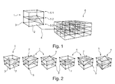
- Figure 1 shows a unit cell 1 being of box-type.
- the unit cell 1 has a plan or footprint 2 which is a square.
- the unit cell 1 comprises nodal points 3 at the vertical edges of the unit cell 1.
- three nodal points 3 are provided at each box edge in equidistant spacing. This results in a square arrangement of nodal points 3 in three levels 5.1, 5.2, 5.3 at different z coordinates.
- the unit cell 1 can be combined into a larger orthogonal grid 6, as an arrow 4 symbolizes.
- the unit cell 1 is the basis to generate a kit of elements.
- Figure 1 shows one embodiment of such kit. This will be described in more detail with reference to Figure 2 .
- unit cells 1 are located side by side and in stacked configuration.
- the orthogonal grid can cover any desired 3D volume and allows to generate 3D structures of any desired geometrical extension.
- the grid and the coordinates system can have oblique axes.
- the grid can be assembled from several different unit cells, wherein neighbouring unit cells (either within one level or across the levels) may be different. As pre-requisite, the arrangement of unit cells must fill the 3D space gap-less.
- Figure 2 shows a kit of elements 7 generated from the unit cell 1.
- the elements 7 are generated by selecting all permutations of nodal points 3 at the four cell edges of the box-type unit cell 1.
- the leftmost embodiment in Figure 2 is a planar element 7 being obtained from connecting the nodal points 3 at the central level of the box-type unit cell 1.
- Straight elements edges connect nodal points at neighbouring edges of the unit cell 1. This results in a frame which can be filled to obtain a bulk-type element 7 or remains unfilled, if the structure shall be of a mesh-type. Similar elements 7 are generated for different selections of nodal points 3.
- Rods 8 extending from a centre point 12 of the unit cell 1 to the nodal points 3 form each element 14 ( Fig. 3 ).
- the methodology of selecting different permutations of nodes is the same although the number and distances of levels in the unit cell 1 may be different.
- Each rod extends from the centre point 12 to a node 3 which was selected when going through the possible permutation of nodes 3.
- the elements 14 comprise a star-shaped configuration. These star-shaped elements 14 can be connected at the ends of the respective rods 8 to form a structure.
- the structure has the form of a mesh, if fields between neighbouring elements 14 remain unfilled. If the fields are filled, one obtains a surface structure.
- a structure being of a mesh-type is still gap-less as the mesh extends over any desirable continuous 3D form.
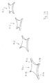
- the number of star-shaped elements 14 obtained by the approach according to Figure 3 is generally larger than the number of elements 7 obtained by the approach of Figure 2 . Further, the star-shaped elements 14 according to Figure 3 always have a centre point 12 located in the centre of the unit cell 1 at which centre point 12 all rods 8 meet. This automatically results in an articulated surface for such elements 14 if fields between neighbouring elements 14 are filled.
- Figures 4(a)-(e) show five examples of elements 7.1, 7.2, 7.3, 7.4 and 7.5 for a unit cell 1 which has a square plan but five levels of square arrangement of nodal points 3. Of course a higher number of levels is possible. This allows for larger inclinations in the structure 10, namely when the z step difference between nodal points 3 of neighbouring cell edges differ by more than one z level.
- the method of generating the elements 7, 14 prescribes how many z level differences are allowed. In the embodiment of Figure 4 , this number is two, whereas in the embodiment of Figure 2 the maximum allowed number is one.
- Figure 4(d) which is shown in Figure 8 in a magnified view emphasizes that the corners 9.1, 9.2, 9.3 and 9.4 of each element 7 are located precisely at a nodal point 3 of the unit cell 1. With the neighbouring nodal points 3 being connected by straight element edges, interfacing of different elements 7 is easily possible as long as only elements 7 are adjoined which have the same inclination of element edges. Further, all element edges have the same thickness 11 in z direction which assist easy interfacing. The thickness is one parameter which can be selected when generating the kit.
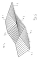
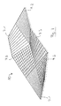
- Figures 5-7 show different building parts 10 constructed or composed from elements 7.1, 7.2 and 7.3 in different configuration. As one easily sees, the building parts 10 of Figures 5-7 are quite different but still utilize the same elements 7 of the same kit. This shows the great degree of freedom the kit gives when designing a building as well as when constructing or composing such building or building part 10.
- the building parts 10 of Figures 5-7 can also be obtained from the star-shaped elements 14.
- the respective rods 8 are shown additionally and as an example in Figure 3 by dashed lines.
- the centre points 12 are located at vertices of the building part 10. Each rod 8 extends from a centre point 12 to a connection 13 (symbolized by open rings in Figure 5 ) with the next rod 8 of the neighbouring element 14.
- Both ways of generating the building part 10 are possible, i.e. either using elements 7 obtained from a frame interconnecting the nodal points 3 of the unit cell 1 or star-shaped elements 14 obtained from connecting each nodal point 3 with the centre point 12 by a rod 8.
- the only difference is that the star-shaped elements 14 initially always generate a mesh-type structure. It can easily be converted to a surface type structure by filling the open fields between the mesh of rods 8 as desired.
- the embodiment of generating elements 7 allows to directly obtain bulk-type elements, i.e. elements in which the frames are already filled. Combining such elements immediately results in a surface type structure. Of course, it is also possible to fill the frames of the elements 7 only after the elements have been combined to compose a mesh-type structure 10.
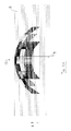
- Figure 9 shows a side view of a building part 10 which has the form of a dome. In the side view, the height of the different elements 7 is fairly different.
- Figure 10 shows a view of the building part 10 from the top, which is in fact a projection of the building part 10 into the x-y plane. Due to the generating method used all elements 7 have the same cross-section in the x-y plane which cross-section is identical to the footprint of the unit cell 1. The footprint is a square allowing easily to fill the x-y plane which is required to obtain a continuous and gap-less 3D building part 10.
- Figure 11 shows a representation similar to that of Figure 9 ; the grid is symbolized here by horizontal lines.
- Figure 12 shows a top view of a similar building part 10.
- the kit of elements now uses two different types of unit cells.
- One unit cell has a square footprint resulting in elements 7a having a square footprint as well, and the other unit cell has a cross-section of a regular triangle resulting in elements 7b having such footprint.
- the cross-section of the two unit cells is selected such that a combination of copies of this cross-section allows to fill the plane.
- the edges of the regular triangle and of the square are of same lengths. However, this is not mandatory.
- Figure 13 shows a side view of the building parts 10 having a combination of elements 7 of square footprint and elements 7b of triangle footprint.
- Figure 14 shows that the frame-type elements 7 obtained according to the principle of the embodiment of Figure 2 and the star-shaped elements 14 obtained according to the principle of the embodiment of Figure 3 are analogous forms of each other.
- Figure 14 shows the unit cell 1 and an example of a frame-type element 7 derived from this unit cell.
- the Figure further shows four star-shaped elements 14 the centre points 12 of which are located at the vertices of the element 7.
- the rods 8 of the star-shaped elements 14 extend along the element edges of the element 7.
- the rods are connected at their ends, and the elements 14 are combined such that the rod of one element is in continuation of the rod of the next element.
- the star-shaped elements 14 are connected such that only rods 8 are connected which have the same angle against the base plane of the unit cell. Obeying this rule results in the rods 8 of the elements 14 being located along the element edges of the element 7.
- Figure 15 shows a building part 10 which was generated from elements 7.
- Figure 16 shows a very similar building part 10 generated from elements 14.
- a comparison of both views clearly shows the similarity as well as the difference between the elements 7 and 14.
- Elements 7 are connected along their element edges.
- Elements 14 are connected at the ends 16 of rods 8.
- Using the elements 7 always result in a closed edge of the building part 10, whereas the elements 14 result in an open edge 15. If such open edge is not desired, it is to be closed by a connection or by using a further star-shaped element which may have a lesser number of rods to allow a closed edge of the building part 10.
- the star-shaped elements 14 give a higher degree of freedom for the surface itself.
- the opening between a set of four star-shaped elements 14 in Figure 16 can be left open or closed by any structure, which in particular needs not to be plane. E.g. one could use dome-shaped parts to close the openings between a set of four star-shaped elements 14.
- the star-shaped elements 14 needs not to have exactly four rods 8.
- the number of rods is equal to the number of edges of the footprint 2 of the unit cell 1.
- elements 7 were obtained from a unit cell 1 having a square footprint 2 resulting in elements 7 having four vertices and elements 14 having four rods. The number may be different, of course.
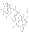
- Figure 17 shows another example of elements 7 which have element edges being not straight.
- Three elements 7.1, 7.2 and 7.3 are displayed. These have element edges 17.1, 17.2 and 17.3.
- the element edges may be straight (suffix "a”) angled in a first orientation (suffix "b") or angled in a second orientation (suffix "c)".
- Figure 17 shows that the elements 7 need not to have a filled frame, which frame is defined by the element edges. This generally applies to elements 7 of all types.
- Figure 18 shows a plane view of the element of Figure 17 making it clear that all elements 7.1-7.3 of Figure 17 have the same footprint 2 which is a square.
- the sub-grit must not be confused with the square footprint 2. It is part of a special design of the elements 7.1-7.3 of Figures 17-18 .
- Figure 19 shows a building part 10 having a general form being identical to the building part of Figure 15 .
- the elements 7 used to compose or construct the building part 10 of Figure 19 have overall straight element edges 17, which, however, have edge recesses 18.
- an opening 19 is generated in the building part 10. This opening may or may not be closed later.
- Figure 21 shows a plane view of the elements 7 used for composing or constructing the building part 10. As can be seen, the location of the recesses 18 at the element edges 17 can be varied to a great extend. In the embodiment shown in Figure 21 , any recesses 18 are always located at the same position at an element edge 17. This is not mandatory.
- Figure 22 shows a perspective view of the elements 7 of Figure 21 .
- three types of elements edges exist. Straight edges having a recess 18 (suffix "a”), inclined edges of a first orientation (suffix "b”) and of a second orientation (suffix "c").
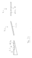
- Figure 23 shows a side view of the elements of Figure 22 .
- Figure 24 shows a building part 10 composed or constructed from star-shaped elements 14 which have special types of rods 8.
- the rods are not simple straight bars having parallel side faces but are arrow-like resulting in curved connecting faces 20 between neighbouring rods.
- the star-shaped elements 14 are identical to the rod-type star-shaped element 14 of Figure 14 .
- rods 8 of the same inclination are connected to form the building part 10, and between a set of four connected elements 14, an opening exists.
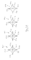
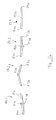
- Figure 25 shows a plane view, Figure 26 a side view and Figure 27 a perspective view of the four elements 14 used in the building part 10.
- the four rods are identified by suffixes "a”, “b”, “c” and “d” for each rod.
- a further suffix ".1”, “.2”, “.3” and “.4" identifies the individual elements 14 and their rods 18.
- the rods 8 of the elements 14 of Figures 24-27 are angled to each other with the vertex being located at the centre point 12, because the rods 8 are straight. However, curved rods are equally possible as Figures 28-29 show. Each rod 8 is curved along a main axis which runs from the centre to the end of the rod. When connecting elements 14, rods are connected which have the same inclination regarding the main axis. The effect of this rule is that the openings between a set of connected elements 14 have a continues edge.
- the rods 8 do not have concave connection faces 20 but convex ones. This results in exactly the negative of Figure 28 , i.e. the openings in Figure 28 turn to elements 14, and the elements 14 are converted to openings.
- the elements 7 or 14 can be used for designing buildings or other structures. In this embodiment, the elements are used in a software. The elements 7 or 14 can also be used to build a building in real world. The described method of generating elements, thus, relates to software and computer programs as wells as to building real world elements and constructing buildings or structures therefrom.
- the important feature of the unit cell based method is the control of the footprint and number of elements which are generated and then used for composing or constructing gap-less surface or frame structures. Two factors determine how many members a particular kit of elements forms.
- the cross-section of the unit cell influences the number of members of the kit.
- the basic square kit of elements has fewer members, six unique shapes, than the rectangular kit, which has thirteen.
- the reason is that the rectangular unit cell frame has two different lengths of edges.
- the second cause that increases the number of parts is the value for the allowed stepping in the z direction. It is linked to the process of placing vertices up or down, or keeping them level. The number of possible combinations of vertex positions depends on the value of the level steps allowed. For instance, when two level steps are allowed (as in Figs. 4 and 8 ), the procedure goes through all combinations of placing vertices one unit or two units up; the same is possible when the vertices are placed downwards, or they are kept at the same level.
- each element is described by a sequence of vectors (x, y, z).
- the x and y values of each element are the known parameters. They are defined through the parameter settings, wherein z is a variable.
- An element is described by providing a sequence of z values of its vectors, as x and y are already identified.
- the programme code generates a kit by going through all the possible vector combinations within the constraints. These constraints, expressed in the general notation, are n, the number of edges, and s, the number of level steppings.
- the vectors can go s levels up or down, or remain at the same level. A rule which only allows s level stepping between the neighbouring vertices is applicable here.
- the vector strings are checked to see if they define valid elements, i.e. closed frames. A description is valid if the sum of the z-vector values is 0. Valid elements are then compared, to filter out repetitions. Repetitions are rotations of the same vector sequence. Unique elements are recognised and their rotations are identified as types that have been defined already.
- the program comprises three parts:
- the generation of a kit is implemented as a linear counting procedure and then as a grouping procedure.
- the number of elements is counted, at the same time as the vectors are stored which are necessary to actually draw the geometries.
- This combines the control of the number, as well as the geometrical definition of the elements.
- An element factory program class was split into two separate streams, one for each representation: one to generate tiles and the other to generate nodes. This important decision is of advantage (but not mandatory), as it is fundamentally different to only changing the way in which the elements were displayed on the screen. This structure suggests a future extension to the program, where the user can pick individual elements from the preview and, in this way, decide which element enters the form-generating process.
- kits are form families, of which each part can be connected to itself or to the other parts of the same family in various ways. Different larger surface geometries can be created using the same kit of elements.
- the unit cell is an architecturally integrated system.
- the geometries defined within this grid will be repetitive if the matrix is regular, featuring repetitive cells, i.e. copies of cells.
- the term "repetition" here involves repeated shapes and repeated angles between parts, and thereby connections and nodes.
- the more complex the grid the more complex the geometry system defined within it.
- the grid can be associated with any coordinate system: the Cartesian coordinate system of the current implementation can, for example, be replaced by a polar coordinate system.
- elements which are defined through the process of a combinational definition of vectors in a particular unit cell frame, such as an orthogonal box create a kit of elements. These elements carry shared features, namely the length and the shape of their edges, which allow them to be connected to each other. They also have distinct geometric characteristics through the different combinations of diagonally lifted, horizontal or lowered vectors. The distinction allows for diversity in global configurations when connecting the elements.
- Each kit of elements created in a particular unit cell will create a catalogue of possible global geometry configurations.
- the principle of repetition can be maintained, if through spatial congruent transformations which are shape- and distance-preserving transformations (translation and rotation), one unit cell fits into different unit cells of the same cell assembly.
Landscapes
- Engineering & Computer Science (AREA)
- Physics & Mathematics (AREA)
- Theoretical Computer Science (AREA)
- Geometry (AREA)
- Computer Hardware Design (AREA)
- General Physics & Mathematics (AREA)
- Evolutionary Computation (AREA)
- General Engineering & Computer Science (AREA)
- Architecture (AREA)
- Civil Engineering (AREA)
- Structural Engineering (AREA)
- Computational Mathematics (AREA)
- Mathematical Analysis (AREA)
- Mathematical Optimization (AREA)
- Pure & Applied Mathematics (AREA)
- Toys (AREA)
- Prostheses (AREA)
Abstract
Description
- The invention relates to kit of elements adapted for composing or constructing diverse, gap-less 3D structures, in particular to a kit of elements which can be used for designing of buildings as well as constructing such buildings. The invention further relates to a method of generating such kit of elements.
- There is a trend in architecture to provide buildings with surface geometries which go beyond usual planar surfaces and to use curved surfaces for building shells, roofs or support constructions of such structures. Nowadays 3D curved surfaces are rather troublesome to design and constructing such requires custom-made components. Both aspects significantly contribute to building costs.
- The invention addresses this need in architecture and the building industry. It is an objective of the invention to provide a kit of elements which allows easy design of diverse, gap-less 3D structures.
- It is a further object of the invention to provide a kit of elements such that these elements can also be used as components for constructing structures.
- It is a further object of the invention to provide a kit of elements having a geometry which can be used for composing as well as for construction of a structure, wherein the interface of neighbouring elements allows for easy connections of neighbouring elements.
- It is a further object of the invention to provide a method for generating a kit of elements which is parametric to allow a user to influence the number, footprint and thickness of elements and the resolution at which a curved surface can be composed from the kit of elements.
- These and further objects are achieved by the invention in providing a method for generating a kit of elements adapted for composing or constructing diverse, gap-less 3D structures, which method comprises the following steps:
- (a) defining a coordinate system comprising a z axis,
- (b) defining a unit cell or a set of unit cells with each unit cell having the geometrical shape of a generalized cylinder a cross section of which in a certain plane is a simple polygon having corners, the side surface of the respective unit cells thus having cell edges each extending from one of the corners and parallel to the z direction, wherein the cross section of all unit cells are adapted to fill the certain plane gap-less by adjoining several copies of the polygons, wherein the certain plane is at a pre-defined angle to the z axis, in particular at 90°,
- (c) defining for the unit cell or for each unit cell a group of nodal points located on the cell edges wherein all cell edges have nodal points of the same number and in the same equidistant spacing along the z axis, resulting in the nodal points of each unit cell being organized in levels parallel to the certain plane and equidistant along the z axis,
- (d) defining a maximum allowed number of level step difference along the z axis, and
- (e) generating an element of the kit by
- -- selecting for one of the unit cells at each cell edge a single one of the nodal points, wherein selected nodal points, which belong to neighbouring cell edges, differ in their level step difference along the z axis not more than the maximum allowed number,
- -- forming a frame-type element by connecting each of the selected nodal points with its neighbours, which belong to neighbouring cell edges, by an element edge selected from a set of edge curves, wherein for each level step difference a certain edge curve is predefined, or forming a star-shaped element by connecting the selected nodal points with a centre point located centrally in the unit cell by rods selected from a set of rod shapes, wherein for each level step difference a certain rod shape is predefined, and
- -- adding the element to the kit,
- (f) wherein different elements of the kit are generated by repeating step (e) for all unit cells and for different selections of nodal points.
- The objects are further achieved by a kit of elements adapted for composing or constructing diverse, gap-less 3D structures, wherein
- the elements are tiles or frames each comprising corners connected by element edges of certain standard thickness in a z direction, and
- wherein all element edges are either level with the x-y plane or have a mean inclination to the x-y plane being selected from a group of inclinations, in particular from a group of inclinations each having an angle to the x-y plane the sinus of which angle is n-fold of a z level spacing value, wherein in particular the elements have in projection to a x-y plane a simple polygonal footprint which is adapted to fill the x-y plane gap-less by adjoining several copies of the footprint or footprints.
- The objects are further achieved by a kit of elements adapted for composing or constructing diverse, gap-less 3D structures wherein
- the elements are star-shaped each comprising rods extending from a centre point, and
- wherein all rods are either level with the x-y plane or have an inclination to the x-y plane being selected from a group of inclinations, in particular from a group of inclinations each having an angle to the x-y plane, the sinus of which angle is n-fold of a z level spacing value, in particular the elements have in projection to a x-y plane a footprint which is adapted to fill the x-y plane gap-less by forming a mesh in adjoining several copies of the footprint.
- The invention relates to designing structures. This is herein referred to as "composing" a structure from the kit of elements. The invention also relates to building a structure in real. This is herein referred to as "constructing" a structure from the kit of elements.
- The structures may be one or more of the following: Building hulls (envelopes), roofs, facades, internal walls, partitions, shells, cladding, substructures, frame structures and surface structures.
- In step (e) the finalizing may include filling the closed frame.
- The invention is based on the principle of a unit cell. The unit cell is a geometric principle that allows families of elements, so called kits, to be generated. The features of the system are:
- the unit cell model derives elements from the controlled variations of a polygonal shape,
- the elements can be assembled to form a diversity of global 3D geometries,
- these geometries are articulated 3D surfaces, preferably gap-less.
- The unit cell itself is a three-dimensional parametric reference frame that is a part of a larger three-dimensional grid. The main characteristic of the elements which are created by a particular unit cell is that the same elements can be assembled to form a wide range of different surface geometries. The rules controlling how the elements connect are intrinsic in their geometry and defined by the edges along which the elements connect. An element can fit with copies of itself, or other elements and their rotations, if they share a compatible edge. Each element of the kit is unique and yet shares certain geometric edge features with the other elements of the kit. Shared edge features allow the parts to be connected to each other in different ways; features which distinguish them create the differentiation and articulation of the 3D surface to be build.
- The key aspects of the unit cell are: the control of the number of elements which are created, and which are used for creating gap-less surface or frame structures; the recombinability of these elements, so that the same set of parts can form many diverse 3D surface configurations, not just one. The system also considers the orthogonal physical offset of the parts, and through the explicit discreteness of their geometry, the transferability between different modelling and analysis applications. The local geometric elements are controlled upfront, and yet the elements which evolve are not overlapping or branching out, but are continuous entities (unless openings are desired).
- The method and kit represent the building elements generically. This implies that the elements can be placeholders without the necessity of an explicit local form and material association. As an alternative, the elements are realized to construct a building or building structure. This involves building the elements from material, e.g. from concrete, glass, metal etc.
- The frame-type elements are connected at compatible edges. To obtain such compatible edges, the nodes of the unit cells are connected by an edge which is selected from a pre-defined set of edge shapes. For each z level step difference a certain edge shape is provided. This ensures that edges having the same inclination (as related to the z level spacing difference) are compatible and respective elements having such compatible edges can be connected easily.
- The same principle is used for the star-shaped element rods which are to be connected, i.e. have the same inclination as regarding the angle between the centre point and the end of the rods have the same rod shape. At a first glance this feature seems not to be essential, as the ends of the rods might be connected even for different shapes of the rods. However, the feature that only rods of the same shape are connected has the result that any frame within a network of connected star-shaped elements comes from a limited number of geometric forms. The feature that the rod-shaped elements for any inclination (referred to the angle between the centre point and the nodal point, i.e. the end of the rod) have the same rod shape allows an easy filling of the open fields between an interconnected mesh of rods, as these open fields are of very limited geometrical variation. A simple set of elements allows to fill such mesh fully (or with pre-defined gaps, if desired).
- The method of generating a kit of elements first defines the unit cell. In the most simple configuration, the unit cell can have a box form, i.e. the cross-section of the unit cell is a square. This is a very simple example of a generalized cylinder. It is important to note that this specification understands the terms "simple polygon" and "cylinder" according to standard mathematical meaning. A cylinder is not restricted to circular cross-sections and can be generated by translating a footprint along an axis, here the z axis. According to this methodology, a square box is also a cylinder. When generating a cylinder the footprint needs not to be translated along an axis being perpendicular to the footprint. This is only the case when the z axis is an axis of a Cartesian coordinate system. The cylinder is then a right cylinder.
- The certain plane is usually a x-y plane of a rectangular coordinate system. However, oblique axes are possible, too.
- The unit cell has a side surface having edges above the corners of the polygonal footprint of the unit cell. In the box-type unit cell, these edges are the vertical edges of the box. The nodal points are located on the cell edges, wherein each cell edge has the same number of nodal points and the nodal points on the cell edges have the same equidistant spacing in z direction, i.e. along the edge. This results in the fact that the nodal points of each unit cell are organized in levels parallel to the certain plane and equidistant in the z direction.
- A box-type unit cell has three nodal points at each cell edge resulting in twelve nodal points with each level containing four nodal points in the square configuration of the footprint of the box. The individual elements of the kit of elements are generated by selecting on each edge of the box a nodal point, connecting neighbouring nodal points with straight element edges, resulting in a closed frame. This frame is filled and the thus obtained element is provided with a predefined thickness in z direction at its element edges.
- An important aspect of the invention provides a rule how much z spacing is allowed between neighbouring nodal points. These are nodal points which belong to neighbouring cell edges. This maximum allowed number of level step differences in z direction has a strong influence on the number of possible elements and, moreover, on the question how inclined an element might be.
- According to this concept, all elements generated have the same footprint in the x-y plane. It is an important aspect of the invention that this footprint is selected such that it is possible to fill a plane gap-less by adjoining copies of this footprint in neighbouring configuration. Otherwise, it would not be possible to generate gap-less 3D structures.
- Another important aspect of the method for generating the kit and important feature of the kit is that the thickness (measured along the z coordinate) of the element edges is constant independent of the specific element and more important independent of the inclination of this element or edge. This allows an easy interfacing of neighbouring elements of the kit.
- The unit cell concept further has the effect that the inclinations of element edges are either zero (refer to the x-y plane) or have an angle with the x-y plane which comes from a fixed group of discrete angles. Since the elements all have the same footprint when being projected in the x-y plane, this angle related feature has the effect that the lengths of the element edges come from a fixed set of lengths.
- The above mentioned feature of equidistant spacing of the levels in which the nodal points are organized can be dispensed within certain applications. If, however, this feature is used, it results in the fact that the mentioned set of angles only comprises angles being the arcsin of the n-fold of the z level spacing.
- A kit of elements is created by going through all combinations of vertex displacement within a specific unit cell. In a simple embodiment, the unit cell is of a square footprint and has two levels. The distance between the central horizontal plane, and the upper and the lower planes is defined as one unit step. The starting point is four vertices in a plane, and the process goes through all of the permutations of placing vertices one unit step up or down, or keeping them level. Thus, a rule which only allowed one unit step between the neighbouring vertices was applied. This produces a kit with six unique elements, one of them a flipped version of another, i.e. these two elements are symmetrical to each other in reference to the x-y plane. The form with only one vertex lifted was in principle the same as the one with one vertex lowered.
- In some embodiments, however, the two symmetrical elements are still distinctive, in particular when it comes to a generalisation of the representation of materials and types of connections. For example, if the elements represented a build-up of different layers of materials, then the elements must not be flipped upside down.
- In this embodiment, all elements exhibit a square footprint in projection, which means that the elements edges which are connected to a raised or lowered vertex are longer than those connected to a vertex with no displacement. In this particular embodiment, the six forms show two different types of element edges, which were distinct through their orientation (horizontal or diagonal), the corresponding lengths and, if the element edge was inclined, the direction. These characteristics determine whether one element fitted to another one in a particular rotation.
- In one embodiment, the forms are indexed as vectors and sequenced in a particular order, so that if an edge is inclined, the position in the sequence and its prefix indicates the direction of the inclination. The method is also applicable to a basic family of nodes. The same process applies to the creation of a kit of elements. In a simple embodiment based on a square footprint polygon, the starting point is a central node with four rods coming out of it, one vertex at the end of each rod. Each vertex forms a nodal point. At the beginning, the vertices lie in a plane, and the method goes through all the permutations of placing them one level up or down, or keeping them level. This produces 24 unique elements.
- The method using one or several unit cells works as an "element factory". The name indicates its utility as a custom element generator. It can be implemented as a separate class to a plugin, e.g. can be written in the C# language for the host CAD application Rhinoceros which is well known to designers and architects. Elements are generated under user specifications at the beginning of the method. It is an open generative engine which creates element kits on the fly, in accordance with the user input. The method is an extendable parametric system, which is preferred over the idea of supplying a hard-coded, and thereby fixed, geometry set.
- The parameters of the element factory are:
- Number of edges: the number of edges that the polygon of the unit cell has.
- Length of the edges: this parameter refers to the width and the length of the unit cell. Facing element edges must be of the same length, but non-facing element edges can be of different lengths. For instance, the square tile element of
Fig. 1 has four edges and in projection all have the same length, but a rectangle would have two different types of edge length. - Height of the unit cell: the measure of one level step in the z-direction. The height of the unit cell affects the angle between the neighbouring elements and thereby the length of that edge.
- Number of allowed steps in the z-direction (stepping value): the variable that indicates how many levels a vertex can go up or down relative to its neighbours, when iterating through the combinations of vertex positions. A stepping value of one, for example, specifies that the vertex can go up or down by one level. Each setting produces a particular kit of elements.
- The invention is described in more detail with reference to the drawings in which:
- Figure 1
- shows a unit cell and how it is assembled to a larger orthogonal grid,
- Figure 2
- shows an embodiment of kit of elements generated with the unit cell of
Figure 1 , - Figure 3
- shows another embodiment how to generate a kit of elements,
- Figures 4(a)-(e)
- show an embodiment of five elements of a kit generated with a method using a unit cell similar to that of
Figure 1 , - Figures 5-7
- show different building parts obtained by combining elements of the kit of
Figure 2 , - Figure 8
- shows a magnified view of
Figure 4(d) , - Figure 9
- shows a side view of an other building part constructed from a kit of elements being similar to that of
Figure 2 , - Figure 10
- shows a plane view of the building part of
Figure 9 , - Figure 11
- shows a side view similar to that of
Figure 9 in relation to the orthogonal grid utilized, - Figure 12
- shows a plane view similar to that of
Figure 10 for a kit of elements using two types of unit cells, - Figure 13
- shows a side view of the building structure of
Figure 12 , - Figure 14
- shows an isometric view of the unit cell frame of
Figure 1 together with an example of a frame-type element 7 according to the principle of the embodiment ofFigure 2 and several star-shaped elements generated according to the principle of the embodiment ofFigure 3 , wherebyFigure 14 shows that a surface element can be generated from both types of elements, - Figure 15
- shows a building part generated from frame-type elements generated according to the principle of the embodiment of
Figure 2 , - Figure 16
- shows a
similar building part 10 build from star-shaped elements which have been generated according to the principle of the embodiment ofFigure 3 , - Figure 17
- shows three frame-
type elements 7 having angled element edges, - Figure 18
- shows a plane view of the three elements of
Figure 17 , - Figure 19
- shows a building part similar to that of
Figures 15 and16 generated from frame-type elements having recesses resulting in openings in thebuilding part 10, - Figure 20
- shows a plane view of the
building part 10 ofFigure 19 , - Figure 21
- shows a plane view of the elements used to compose or construct the
building part 10, - Figure 22
- shows an isometric view of the elements of
Figure 21 , - Figure 23
- shows a side view of the elements of
Figure 22 , - Figure 24
- shows another
building part 10 composed or constructed from star-shaped elements generated according to the principle ofFigure 3 , - Figure 25
- shows a plane view of the four types of star-shaped elements used in the
building part 10, - Figure 26
- shows a side view of the elements of
Figure 25 , - Figure 27
- shows a perspective view of the elements of
Figure 26 , - Figure 28
- shows a
building part 10 similar to that ofFigure 24 composed or constructed from star-shaped elements similar to those ofFigures 25-27 , and - Figure 29
- shows an isometric view of the elements used to compose or construct the
building part 10 ofFigure 28 in a view similar to that ofFigure 27 . -
Figure 1 shows aunit cell 1 being of box-type. In other words, theunit cell 1 has a plan orfootprint 2 which is a square. Theunit cell 1 comprisesnodal points 3 at the vertical edges of theunit cell 1. In the embodiment shown, threenodal points 3 are provided at each box edge in equidistant spacing. This results in a square arrangement ofnodal points 3 in three levels 5.1, 5.2, 5.3 at different z coordinates. Theunit cell 1 can be combined into a largerorthogonal grid 6, as anarrow 4 symbolizes. Theunit cell 1 is the basis to generate a kit of elements.Figure 1 shows one embodiment of such kit. This will be described in more detail with reference toFigure 2 . In theorthogonal grid 6,unit cells 1 are located side by side and in stacked configuration. Thereby, the orthogonal grid can cover any desired 3D volume and allows to generate 3D structures of any desired geometrical extension. The grid and the coordinates system can have oblique axes. The grid can be assembled from several different unit cells, wherein neighbouring unit cells (either within one level or across the levels) may be different. As pre-requisite, the arrangement of unit cells must fill the 3D space gap-less. -
Figure 2 shows a kit ofelements 7 generated from theunit cell 1. Theelements 7 are generated by selecting all permutations ofnodal points 3 at the four cell edges of the box-type unit cell 1. The leftmost embodiment inFigure 2 is aplanar element 7 being obtained from connecting thenodal points 3 at the central level of the box-type unit cell 1. Straight elements edges connect nodal points at neighbouring edges of theunit cell 1. This results in a frame which can be filled to obtain a bulk-type element 7 or remains unfilled, if the structure shall be of a mesh-type.Similar elements 7 are generated for different selections ofnodal points 3. - Another approach of generating the elements is using the already explained rod-based approach.
Rods 8 extending from acentre point 12 of theunit cell 1 to thenodal points 3 form each element 14 (Fig. 3 ). The methodology of selecting different permutations of nodes is the same although the number and distances of levels in theunit cell 1 may be different. Each rod extends from thecentre point 12 to anode 3 which was selected when going through the possible permutation ofnodes 3. Thus, theelements 14 comprise a star-shaped configuration. These star-shapedelements 14 can be connected at the ends of therespective rods 8 to form a structure. The structure has the form of a mesh, if fields betweenneighbouring elements 14 remain unfilled. If the fields are filled, one obtains a surface structure. - According to the understanding of this invention, a structure being of a mesh-type is still gap-less as the mesh extends over any desirable continuous 3D form.
- The number of star-shaped
elements 14 obtained by the approach according toFigure 3 is generally larger than the number ofelements 7 obtained by the approach ofFigure 2 . Further, the star-shapedelements 14 according toFigure 3 always have acentre point 12 located in the centre of theunit cell 1 at whichcentre point 12 allrods 8 meet. This automatically results in an articulated surface forsuch elements 14 if fields betweenneighbouring elements 14 are filled. -
Figures 4(a)-(e) show five examples of elements 7.1, 7.2, 7.3, 7.4 and 7.5 for aunit cell 1 which has a square plan but five levels of square arrangement ofnodal points 3. Of course a higher number of levels is possible. This allows for larger inclinations in thestructure 10, namely when the z step difference betweennodal points 3 of neighbouring cell edges differ by more than one z level. The method of generating theelements Figure 4 , this number is two, whereas in the embodiment ofFigure 2 the maximum allowed number is one.Figure 4(d) which is shown inFigure 8 in a magnified view emphasizes that the corners 9.1, 9.2, 9.3 and 9.4 of eachelement 7 are located precisely at anodal point 3 of theunit cell 1. With the neighbouringnodal points 3 being connected by straight element edges, interfacing ofdifferent elements 7 is easily possible as long asonly elements 7 are adjoined which have the same inclination of element edges. Further, all element edges have thesame thickness 11 in z direction which assist easy interfacing. The thickness is one parameter which can be selected when generating the kit. -
Figures 5-7 showdifferent building parts 10 constructed or composed from elements 7.1, 7.2 and 7.3 in different configuration. As one easily sees, thebuilding parts 10 ofFigures 5-7 are quite different but still utilize thesame elements 7 of the same kit. This shows the great degree of freedom the kit gives when designing a building as well as when constructing or composing such building or buildingpart 10. Thebuilding parts 10 ofFigures 5-7 can also be obtained from the star-shapedelements 14. Therespective rods 8 are shown additionally and as an example inFigure 3 by dashed lines. The centre points 12 are located at vertices of thebuilding part 10. Eachrod 8 extends from acentre point 12 to a connection 13 (symbolized by open rings inFigure 5 ) with thenext rod 8 of the neighbouringelement 14. - Both ways of generating the
building part 10 are possible, i.e. either usingelements 7 obtained from a frame interconnecting thenodal points 3 of theunit cell 1 or star-shapedelements 14 obtained from connecting eachnodal point 3 with thecentre point 12 by arod 8. The only difference is that the star-shapedelements 14 initially always generate a mesh-type structure. It can easily be converted to a surface type structure by filling the open fields between the mesh ofrods 8 as desired. - The embodiment of generating
elements 7 allows to directly obtain bulk-type elements, i.e. elements in which the frames are already filled. Combining such elements immediately results in a surface type structure. Of course, it is also possible to fill the frames of theelements 7 only after the elements have been combined to compose a mesh-type structure 10. - Another difference between the frame-
type elements 7 and the star-type elements 14 is the connection requirements. Star-shapedelements 14 are connected at the ends of theirrods 8, whereas frame-type elements 7 are connected along the element edges, i.e. the edges of the frames (either filled or unfilled). - When combining
elements 7 to compose or construct astructure 10, onlysuch elements 7 must be in neighbouring configuration which have the same inclination of their element edge. The same applies to the star-shapedelements 14, however related to the inclination of therods 8. -
Figure 9 shows a side view of abuilding part 10 which has the form of a dome. In the side view, the height of thedifferent elements 7 is fairly different.Figure 10 shows a view of thebuilding part 10 from the top, which is in fact a projection of thebuilding part 10 into the x-y plane. Due to the generating method used allelements 7 have the same cross-section in the x-y plane which cross-section is identical to the footprint of theunit cell 1. The footprint is a square allowing easily to fill the x-y plane which is required to obtain a continuous and gap-less3D building part 10. -
Figure 11 shows a representation similar to that ofFigure 9 ; the grid is symbolized here by horizontal lines. -
Figure 12 shows a top view of asimilar building part 10. The kit of elements now uses two different types of unit cells. One unit cell has a square footprint resulting inelements 7a having a square footprint as well, and the other unit cell has a cross-section of a regular triangle resulting in elements 7b having such footprint. The cross-section of the two unit cells is selected such that a combination of copies of this cross-section allows to fill the plane. In the embodiment ofFigure 12 , the edges of the regular triangle and of the square are of same lengths. However, this is not mandatory. It is equally possible to combine unit cells of a cross-section having different lengths of their edges as long as one can combine the cross-sections to fill the x-y plane. For instance, it is possible to combine unit cells having square cross-section of different dimensions with the edge length of the larger square being n-fold the edge length of the smaller square(s). This approach allows to build building parts with lateral varying resolution. -
Figure 13 shows a side view of thebuilding parts 10 having a combination ofelements 7 of square footprint and elements 7b of triangle footprint. -
Figure 14 shows that the frame-type elements 7 obtained according to the principle of the embodiment ofFigure 2 and the star-shapedelements 14 obtained according to the principle of the embodiment ofFigure 3 are analogous forms of each other.Figure 14 shows theunit cell 1 and an example of a frame-type element 7 derived from this unit cell. The Figure further shows four star-shapedelements 14 the centre points 12 of which are located at the vertices of theelement 7. Therods 8 of the star-shapedelements 14 extend along the element edges of theelement 7. The rods are connected at their ends, and theelements 14 are combined such that the rod of one element is in continuation of the rod of the next element. To guarantee such continuing abutment ofrods 8, the star-shapedelements 14 are connected such thatonly rods 8 are connected which have the same angle against the base plane of the unit cell. Obeying this rule results in therods 8 of theelements 14 being located along the element edges of theelement 7. - In
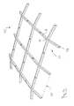
Figures 2 and3 reference was made to theunit cell 1 when generating theelements unit cells 1 are not identically, in particular regarding their location in thegrit 6. As according to the principle ofFigure 3 the centre points 12 of each star-shapedelement 14 are located in the centre of theunit cell 1, it becomes clear that theunit cell 1 shown inFigure 14 relates regarding location and orientation to the generating process of the frame-type element 7. A unit cell which would be used for the star-shapedelement 14 would be shifted, and in some application also rotated against theunit cell 1 shown inFigure 14 . This shift and rotation ensures that (a) the centre points 14 are located in the centre of theunit cell 1, and (b) the rods extend to towards the edges of theunit cell 1. -
Figure 15 shows abuilding part 10 which was generated fromelements 7.Figure 16 shows a verysimilar building part 10 generated fromelements 14. A comparison of both views clearly shows the similarity as well as the difference between theelements Elements 7 are connected along their element edges.Elements 14 are connected at theends 16 ofrods 8. Using theelements 7 always result in a closed edge of thebuilding part 10, whereas theelements 14 result in anopen edge 15. If such open edge is not desired, it is to be closed by a connection or by using a further star-shaped element which may have a lesser number of rods to allow a closed edge of thebuilding part 10. Whereas the principle of composing or constructing thebuilding part 10 fromelements 7 orelements 14 are fairly similar, the star-shapedelements 14 give a higher degree of freedom for the surface itself. The opening between a set of four star-shapedelements 14 inFigure 16 can be left open or closed by any structure, which in particular needs not to be plane. E.g. one could use dome-shaped parts to close the openings between a set of four star-shapedelements 14. - It should be noted that the star-shaped
elements 14 needs not to have exactly fourrods 8. The number of rods is equal to the number of edges of thefootprint 2 of theunit cell 1. In the embodiment ofFigures 15 and16 ,elements 7 were obtained from aunit cell 1 having asquare footprint 2 resulting inelements 7 having four vertices andelements 14 having four rods. The number may be different, of course. -
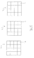
Figure 17 shows another example ofelements 7 which have element edges being not straight. Three elements 7.1, 7.2 and 7.3 are displayed. These have element edges 17.1, 17.2 and 17.3. The element edges may be straight (suffix "a") angled in a first orientation (suffix "b") or angled in a second orientation (suffix "c)". Further,Figure 17 shows that theelements 7 need not to have a filled frame, which frame is defined by the element edges. This generally applies toelements 7 of all types. -
Figure 18 shows a plane view of the element ofFigure 17 making it clear that all elements 7.1-7.3 ofFigure 17 have thesame footprint 2 which is a square. The sub-grit must not be confused with thesquare footprint 2. It is part of a special design of the elements 7.1-7.3 ofFigures 17-18 . -
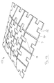
Figure 19 shows abuilding part 10 having a general form being identical to the building part ofFigure 15 . Theelements 7 used to compose or construct thebuilding part 10 ofFigure 19 have overall straight element edges 17, which, however, have edge recesses 18. Incase elements 7 are connected which have edge recesses 18 at the same location along theelement edge 17, anopening 19 is generated in thebuilding part 10. This opening may or may not be closed later. -
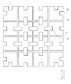
Figure 21 shows a plane view of theelements 7 used for composing or constructing thebuilding part 10. As can be seen, the location of therecesses 18 at the element edges 17 can be varied to a great extend. In the embodiment shown inFigure 21 , anyrecesses 18 are always located at the same position at anelement edge 17. This is not mandatory. -
Figure 22 shows a perspective view of theelements 7 ofFigure 21 . As can be seen, three types of elements edges exist. Straight edges having a recess 18 (suffix "a"), inclined edges of a first orientation (suffix "b") and of a second orientation (suffix "c"). -
Figure 23 shows a side view of the elements ofFigure 22 . -
Figure 24 shows abuilding part 10 composed or constructed from star-shapedelements 14 which have special types ofrods 8. The rods are not simple straight bars having parallel side faces but are arrow-like resulting in curved connecting faces 20 between neighbouring rods. Apart from this feature, the star-shapedelements 14 are identical to the rod-type star-shapedelement 14 ofFigure 14 . Again,rods 8 of the same inclination are connected to form thebuilding part 10, and between a set of fourconnected elements 14, an opening exists. -
Figure 25 shows a plane view,Figure 26 a side view andFigure 27 a perspective view of the fourelements 14 used in thebuilding part 10. Of course, these four elements are only a subset of the kit ofelements 14. The four rods are identified by suffixes "a", "b", "c" and "d" for each rod. A further suffix ".1", ".2", ".3" and ".4" identifies theindividual elements 14 and theirrods 18. - The
rods 8 of theelements 14 ofFigures 24-27 are angled to each other with the vertex being located at thecentre point 12, because therods 8 are straight. However, curved rods are equally possible asFigures 28-29 show. Eachrod 8 is curved along a main axis which runs from the centre to the end of the rod. When connectingelements 14, rods are connected which have the same inclination regarding the main axis. The effect of this rule is that the openings between a set ofconnected elements 14 have a continues edge. - In a further embodiment, the
rods 8 do not have concave connection faces 20 but convex ones. This results in exactly the negative ofFigure 28 , i.e. the openings inFigure 28 turn toelements 14, and theelements 14 are converted to openings. - The
elements elements - The important feature of the unit cell based method is the control of the footprint and number of elements which are generated and then used for composing or constructing gap-less surface or frame structures. Two factors determine how many members a particular kit of elements forms.
- These factors are the cross-section of the unit cell, and the stepping value. The cross-section of the unit cell influences the number of members of the kit. With the same growth parameter setting, the basic square kit of elements has fewer members, six unique shapes, than the rectangular kit, which has thirteen. The reason is that the rectangular unit cell frame has two different lengths of edges. When the elements are generated one embodiment method, the process applies a different filter to that for a square unit cell frame with two symmetry axes. Here, two types of rotation have to be considered and there is only a single axis of symmetry.
- The second cause that increases the number of parts is the value for the allowed stepping in the z direction. It is linked to the process of placing vertices up or down, or keeping them level. The number of possible combinations of vertex positions depends on the value of the level steps allowed. For instance, when two level steps are allowed (as in
Figs. 4 and8 ), the procedure goes through all combinations of placing vertices one unit or two units up; the same is possible when the vertices are placed downwards, or they are kept at the same level. - Another factor is the representation of the elements, whether as surfaces or frames, as demonstrated in
Figs. 2 and3 . There are always more nodes than connection angles and always more connection angles than elements in the case of the same growth parameter setting. - In a programme realising the method, each element is described by a sequence of vectors (x, y, z). The x and y values of each element are the known parameters. They are defined through the parameter settings, wherein z is a variable. An element is described by providing a sequence of z values of its vectors, as x and y are already identified. The programme code generates a kit by going through all the possible vector combinations within the constraints. These constraints, expressed in the general notation, are n, the number of edges, and s, the number of level steppings. The vectors can go s levels up or down, or remain at the same level. A rule which only allows s level stepping between the neighbouring vertices is applicable here. The vector strings are checked to see if they define valid elements, i.e. closed frames. A description is valid if the sum of the z-vector values is 0. Valid elements are then compared, to filter out repetitions. Repetitions are rotations of the same vector sequence. Unique elements are recognised and their rotations are identified as types that have been defined already.
- If one element cannot become the other by a simple rotation, the two elements are distinct. The rotation and translations of an initial form are allowed, and counted as non-unique repetitions of the initial shape. Reflections are not considered to be repetitions.
- The program comprises three parts:
- 1. Configure parameter settings. The user inputs the parameters which determine the features of the elements (shape, representation, height of z-directional level jump and number of allowed level steps).
- 2. Iterate through all possible vector combinations. This process starts from a planar field of vectors and goes through all possible combinations of the vector configurations, considering the number of allowed level steps. Check whether it is a valid element; the z-vectors have to sum up to 0.
- 3. Iterate through all elements and find the unique ones. This part of the procedure filters out those elements which are rotations of unique elements that have already been defined. If the element is not a rotation of an earlier defined element, then it is indicated as a new unique one. Reflections of a particular element count as new, unique ones. Colour coding is assigned, and unique elements and their respective rotations carry the same colour.
- In one embodiment the generation of a kit is implemented as a linear counting procedure and then as a grouping procedure. The number of elements is counted, at the same time as the vectors are stored which are necessary to actually draw the geometries. This combines the control of the number, as well as the geometrical definition of the elements. An element factory program class was split into two separate streams, one for each representation: one to generate tiles and the other to generate nodes. This important decision is of advantage (but not mandatory), as it is fundamentally different to only changing the way in which the elements were displayed on the screen. This structure suggests a future extension to the program, where the user can pick individual elements from the preview and, in this way, decide which element enters the form-generating process.
- The growth model based on the unit cell principle allows the generation of discrete geometry kits. These kits are form families, of which each part can be connected to itself or to the other parts of the same family in various ways. Different larger surface geometries can be created using the same kit of elements.
- This provides a method to generate closed componential surfaces in a bottom-up process using discrete elements. The unit cell is an architecturally integrated system. The control of the number of parts, the known physical offset, the interface to neighbouring parts and the discreteness of the local geometries, which allows geometries to be easily transferred between the necessary software packages, informs the method using real-world parameters.
- Elements which are defined within the three-dimensional unit cell frame, and therefore in a larger three-dimensional grid, carry the features of the underlying grid. The geometries defined within this grid will be repetitive if the matrix is regular, featuring repetitive cells, i.e. copies of cells. The term "repetition" here involves repeated shapes and repeated angles between parts, and thereby connections and nodes. The more complex the grid, the more complex the geometry system defined within it. The grid can be associated with any coordinate system: the Cartesian coordinate system of the current implementation can, for example, be replaced by a polar coordinate system. In summary, elements which are defined through the process of a combinational definition of vectors in a particular unit cell frame, such as an orthogonal box, create a kit of elements. These elements carry shared features, namely the length and the shape of their edges, which allow them to be connected to each other. They also have distinct geometric characteristics through the different combinations of diagonally lifted, horizontal or lowered vectors. The distinction allows for diversity in global configurations when connecting the elements.
- Each kit of elements created in a particular unit cell will create a catalogue of possible global geometry configurations. The greater the repetition in the pattern of the global three-dimensional grid, the greater the number of repeating elements which are defined within this grid. The principle of repetition can be maintained, if through spatial congruent transformations which are shape- and distance-preserving transformations (translation and rotation), one unit cell fits into different unit cells of the same cell assembly.
Claims (15)
- A method for generating a kit of elements (7; 14) adapted for composing or constructing diverse, gap-less 3D structures (10), which method comprises the following steps:(a) defining a coordinate system comprising a z axis,(b) defining a unit cell (1) or a set of unit cells with each unit cell (1) having the geometrical shape of a generalized cylinder a cross section (2) of which in a certain plane is a simple polygon having corners, the side surface of the respective unit cells (1) thus having cell edges each extending from one of the corners and parallel to the z direction, wherein the cross section (2) of all unit cells are adapted to fill the certain plane gap-less by adjoining several copies of the polygons, wherein the certain plane is at a pre-defined angle to the z axis,(c) defining for each unit cell (1) a group of nodal points (3) located on the cell edges wherein all cell edges have nodal points (3) of the same number and in the same equidistant spacing along the z axis, resulting in the nodal points (3) of each unit cell (1) being organized in levels (5.1, 5.2, 5.3) equidistant along the z axis,(d) defining a maximum allowed number of level step difference along the z axis, and(e) generating an element (7; 14) of the kit by-- selecting for one of the unit cells (1) at each cell edge a single one of the nodal points (3), wherein selected nodal points (3), which belong to neighbouring cell edges, differ in their level step difference along the z axis not more than the maximum allowed number,-- forming a frame-type element (7) by connecting each of the selected nodal points (3) with its neighbours, which belong to neighbouring cell edges, by an element edge selected from a set of edge curves, wherein for each level step difference a certain edge curve is predefined, or forming a star-shaped element (14) by connecting the selected nodal points (3) with a centre point (12) located centrally in the unit cell (1) by rods (8) selected from a set of rod shapes, wherein for each level step difference a certain rod shape is predefined, and-- adding the element (7; 14) to the kit,(f) wherein different elements (7; 14) of the kit are generated by repeating step (e) for all unit cells (1) and for different selections of nodal points (3).
- The method according to claim 1, wherein step (e) comprises finalizing the element of the kit by providing the frame-type element (7) at its element edges with a pre-defined thickness along the z axis or by providing the star-shaped element with rods (8) of pre-defined thickness along the z axis at the rod terminals.
- The method according to claim 2, wherein step (e) comprises finalizing the frame-type element of the kit by filling the closed frame.
- The method according to claim 1, 2 or 3, wherein step (e) comprises a checking step in which the element (7; 14) is checked for being a rotated or flipped copy of an already generated element (7; 14), wherein the element (7; 14) is added to the kit only if it is not such copy.
- The method according to any of the above claims, wherein the polygon is or the polygons are regular and have in particular 3, 4, 5, 6 or 8 corners.
- A method for composing or constructing a 3D structure (10), wherein a kit of elements (7, 14) is generated according to the method of any of claims 1-5 and the 3D structure (10) is composed or constructed from the elements (7, 14).
- A computer program comprising software code adapted to perform the method according to any of claims 1 to 6.
- The computer program according to claim 7 realized in form of a module to be loaded into a computer based building construction system and adapted to provide the building construction system with capability to generate the kit of elements.
- A computer-readable storage medium or signal comprising the program of claim 7 or 8.
- A kit of elements adapted for composing or constructing diverse, gap-less 3D structures (10), wherein- the elements (7) are tiles or frames each comprising corners connected by element edges of certain standard thickness in a z direction, and- wherein all element edges are either level with the x-y plane or have a mean inclination to the x-y plane being selected from a group of inclinations, in particular from a group of inclinations each having an angle to the x-y plane the sinus of which angle is n-fold of a z level spacing value, wherein in particular the elements (7) have in projection to a x-y plane a simple polygonal footprint (2) which is adapted to fill the x-y plane gap-less by adjoining several copies of the footprint (2) or footprints.
- The kit according to claim 10, wherein all elements (7) fit into a unit cell (1) having the geometrical shape of a generalized cylinder a cross section (2) of which in the x-y plane is identical to a footprint of the respective element (7), the side surface of the respective unit cell (1) having unit cell edges each extending from one corner of the cross section and parallel to a z direction, wherein the elements (7) fit into the unit cell such that the corners of each element (7) are located on the unit cell edges and wherein the corners of different elements (7) which are associated to the same unit cell edge differ in z direction only by a spacing which is n-times a z spacing constant, with n being an integer from [0; n_max].
- A kit of elements adapted for composing or constructing diverse, gap-less 3D structures (10), wherein- the elements (14) are star-shaped each comprising rods (8) extending from a centre point (12), and- wherein all rods (8) are either level with the x-y plane or have an inclination to the x-y plane being selected from a group of inclinations, in particular from a group of inclinations each having an angle to the x-y plane, the sinus of which angle is n-fold of a z level spacing value, in particular the elements (14) have in projection to a x-y plane a footprint (2) which is adapted to fill the x-y plane gap-less by forming a mesh in adjoining several copies of the footprint (2).
- The kit according to claim 12, wherein all elements (14) fit into a unit cell (1) having the geometrical shape of a generalized cylinder a cross section (2) of which in the x-y plane has the form of a simple polygon and is adapted to fill the x-y plane gap-less by adjoining several copies of the cross section, the side surface of the respective unit cell (1) having unit cell edges each extending from one corner of the cross section and parallel to a z direction, wherein the elements (14) fit into the unit cell such that the ends of the rods (8) of each element (14) are located on the unit cell edges and wherein the ends of the rods (8) of different elements (14) which are associated to the same unit cell edge differ in z direction only by a spacing which is n-times a z spacing constant, with n being an integer from [0; n_max].
- The kit according to claim 10 or 111, wherein the all footprints are regular polygons having 3, 4, 5, 6 or 8 corners.
- The method or the kit of any of the above claims, wherein the rods (8) of the star-shaped element (14) have convex or concave side faces.
Priority Applications (1)
| Application Number | Priority Date | Filing Date | Title |
|---|---|---|---|
| EP14160345.6A EP2921977B1 (en) | 2014-03-17 | 2014-03-17 | Method for generating a kit of elements for composing or constructing diverse gap-less 3d structures and such kit of elements |
Applications Claiming Priority (1)
| Application Number | Priority Date | Filing Date | Title |
|---|---|---|---|
| EP14160345.6A EP2921977B1 (en) | 2014-03-17 | 2014-03-17 | Method for generating a kit of elements for composing or constructing diverse gap-less 3d structures and such kit of elements |
Publications (3)
| Publication Number | Publication Date |
|---|---|
| EP2921977A1 true EP2921977A1 (en) | 2015-09-23 |
| EP2921977B1 EP2921977B1 (en) | 2023-09-20 |
| EP2921977C0 EP2921977C0 (en) | 2023-09-20 |
Family
ID=50389229
Family Applications (1)
| Application Number | Title | Priority Date | Filing Date |
|---|---|---|---|
| EP14160345.6A Active EP2921977B1 (en) | 2014-03-17 | 2014-03-17 | Method for generating a kit of elements for composing or constructing diverse gap-less 3d structures and such kit of elements |
Country Status (1)
| Country | Link |
|---|---|
| EP (1) | EP2921977B1 (en) |
Cited By (3)
| Publication number | Priority date | Publication date | Assignee | Title |
|---|---|---|---|---|
| CN112031149A (en) * | 2020-08-31 | 2020-12-04 | 天津泰明加德低碳住宅科技发展有限公司 | Assembly type building design method based on biological geometric DNA |
| CN112507490A (en) * | 2020-12-03 | 2021-03-16 | 上海市建工设计研究总院有限公司 | Modeling method for axis of externally-packaged special-shaped pipe |
| CN113553651A (en) * | 2021-07-28 | 2021-10-26 | 杭州群核信息技术有限公司 | Split fan generation method and device and storage medium |
Citations (3)
| Publication number | Priority date | Publication date | Assignee | Title |
|---|---|---|---|---|
| US20030108388A1 (en) * | 2001-12-12 | 2003-06-12 | Smith Peter J. | Pre-fabricated warped pavement slab, forming and pavement systems, and methods for installing and making same |
| WO2009128111A1 (en) * | 2008-04-14 | 2009-10-22 | Roberta Ventrella | "structural system made up of plastic three- dimensional spherical joints and aluminium beams for the diy construction of elements for interior decoration and outdoors preparation" |
| US20100139202A1 (en) * | 2008-12-10 | 2010-06-10 | Athan Stephan P | Space frame hub joint |
-
2014
- 2014-03-17 EP EP14160345.6A patent/EP2921977B1/en active Active
Patent Citations (3)
| Publication number | Priority date | Publication date | Assignee | Title |
|---|---|---|---|---|
| US20030108388A1 (en) * | 2001-12-12 | 2003-06-12 | Smith Peter J. | Pre-fabricated warped pavement slab, forming and pavement systems, and methods for installing and making same |
| WO2009128111A1 (en) * | 2008-04-14 | 2009-10-22 | Roberta Ventrella | "structural system made up of plastic three- dimensional spherical joints and aluminium beams for the diy construction of elements for interior decoration and outdoors preparation" |
| US20100139202A1 (en) * | 2008-12-10 | 2010-06-10 | Athan Stephan P | Space frame hub joint |
Non-Patent Citations (3)
| Title |
|---|
| ANONYMOUS: "Dirt, Slope. Sand, Gravel, fluid-ish. Snow Biome suggestion", MINECRAFT FORUM, 24 September 2010 (2010-09-24), pages 1 - 10, XP055139303, Retrieved from the Internet <URL:http://www.minecraftforum.net/forums/minecraft-discussion/suggestions/11943-dirt-slope-sand-gravel-fluid-ish-snow-biome> [retrieved on 20140910] * |
| CHI-WING FU ET AL: "K-set tilable surfaces", ACM TRANSACTIONS ON GRAPHICS (TOG), ACM, US, vol. 29, no. 4, 26 July 2010 (2010-07-26), pages 1 - 6, XP058041061, ISSN: 0730-0301, DOI: 10.1145/1778765.1778781 * |
| KATRIN JONAS ET AL: "ECSS - Evolutionary Component Surface System - A tool for architectural form generation and form optimization", 12 July 2006 (2006-07-12), pages 1 - 4, XP055138840, Retrieved from the Internet <URL:ftp://ftp.cs.bham.ac.uk/pub/authors/W.B.Langdon/biblio/gecco2006etc/papers/wksp136.pdf> [retrieved on 20140908] * |
Cited By (4)
| Publication number | Priority date | Publication date | Assignee | Title |
|---|---|---|---|---|
| CN112031149A (en) * | 2020-08-31 | 2020-12-04 | 天津泰明加德低碳住宅科技发展有限公司 | Assembly type building design method based on biological geometric DNA |
| CN112507490A (en) * | 2020-12-03 | 2021-03-16 | 上海市建工设计研究总院有限公司 | Modeling method for axis of externally-packaged special-shaped pipe |
| CN113553651A (en) * | 2021-07-28 | 2021-10-26 | 杭州群核信息技术有限公司 | Split fan generation method and device and storage medium |
| CN113553651B (en) * | 2021-07-28 | 2024-02-20 | 杭州群核信息技术有限公司 | Split fan generating method, device and storage medium |
Also Published As
| Publication number | Publication date |
|---|---|
| EP2921977B1 (en) | 2023-09-20 |
| EP2921977C0 (en) | 2023-09-20 |
Similar Documents
| Publication | Publication Date | Title |
|---|---|---|
| AU2019445440A1 (en) | Method for the lightweighting and/or designing of an additively manufactured article | |
| CN111611675A (en) | Rapid modeling method based on Revit and Dynamo parameterized grid structure model | |
| KR101959382B1 (en) | Parametric based truss modeling method | |
| US6578189B2 (en) | Hexahedral mesh generation method and device | |
| EP2921977B1 (en) | Method for generating a kit of elements for composing or constructing diverse gap-less 3d structures and such kit of elements | |
| Tellier | Bundling elastic gridshells with alignable nets. Part II: Form-finding | |
| JP2003281201A (en) | Mesh generation method | |
| JP2000259682A (en) | Automatic component placement system and method, and recording medium recording automatic component placement program | |
| KR100340080B1 (en) | Automatic CAD Model Synthesis From Unorganized 3-D Range Data | |
| Imam et al. | Nonlinear programming approach to automated topology optimization | |
| US5737250A (en) | Method and system for simulating ion implantation for performing simulation with avoiding overflow by adjusting memory consuming amount | |
| Gomez-Jauregui et al. | Innovative families of double-layer tensegrity grids: Quastruts and sixstruts | |
| CN112100726B (en) | An Intelligent Generation Method of Plane Orthogonal Multiaxial Bearing Reinforcement | |
| Hou et al. | The computational complexity of finding Hamiltonian cycles in grid graphs of semiregular tessellations | |
| Kaveh et al. | An efficient graph‐theoretical force method for three‐dimensional finite element analysis | |
| Tellier et al. | On the design of torsion-free gridshells | |
| Gomez-Jauregui et al. | Generation and nomenclature of tessellations and double-layer grids | |
| Watada et al. | Shape generation of hexagonal lattice shell consisting of edge offset mesh | |
| Lordick | Intuitive design and meshing of non-developable ruled surfaces | |
| Araujo et al. | Exploring Weaire-Phelan through Cellular Automata: A proposal for a structural variance-producing engine | |
| JPH11272649A (en) | How to create a model for finite element analysis | |
| Rizzuto | Eccentricity orientation of bolted connections in space structure configurations using reciprocally supported elements | |
| CN119962063A (en) | Method, device, electronic device and storage medium for generating architectural free-form surface | |
| Elber et al. | Conformal Microstructure Synthesis in Trimmed Trivariate based V-reps | |
| Zhang et al. | Surface optimization and parametric modeling research on steel roof structure of an exhibition center |
Legal Events
| Date | Code | Title | Description |
|---|---|---|---|
| PUAI | Public reference made under article 153(3) epc to a published international application that has entered the european phase |
Free format text: ORIGINAL CODE: 0009012 |
|
| AK | Designated contracting states |
Kind code of ref document: A1 Designated state(s): AL AT BE BG CH CY CZ DE DK EE ES FI FR GB GR HR HU IE IS IT LI LT LU LV MC MK MT NL NO PL PT RO RS SE SI SK SM TR |
|
| AX | Request for extension of the european patent |
Extension state: BA ME |
|
| 17P | Request for examination filed |
Effective date: 20151116 |
|
| RBV | Designated contracting states (corrected) |
Designated state(s): AL AT BE BG CH CY CZ DE DK EE ES FI FR GB GR HR HU IE IS IT LI LT LU LV MC MK MT NL NO PL PT RO RS SE SI SK SM TR |
|
| STAA | Information on the status of an ep patent application or granted ep patent |
Free format text: STATUS: EXAMINATION IS IN PROGRESS |
|
| 17Q | First examination report despatched |
Effective date: 20190719 |
|
| REG | Reference to a national code |
Ref country code: DE Ref legal event code: R079 Free format text: PREVIOUS MAIN CLASS: G06F0017500000 Ipc: G06F0030130000 Ref document number: 602014088352 Country of ref document: DE |
|
| RIC1 | Information provided on ipc code assigned before grant |
Ipc: G06F 111/20 20200101ALN20230223BHEP Ipc: E04B 1/19 20060101ALN20230223BHEP Ipc: E01C 5/00 20060101ALN20230223BHEP Ipc: G06F 30/00 20200101ALI20230223BHEP Ipc: G06F 30/13 20200101AFI20230223BHEP |
|
| GRAP | Despatch of communication of intention to grant a patent |
Free format text: ORIGINAL CODE: EPIDOSNIGR1 |
|
| STAA | Information on the status of an ep patent application or granted ep patent |
Free format text: STATUS: GRANT OF PATENT IS INTENDED |
|
| RIC1 | Information provided on ipc code assigned before grant |
Ipc: G06F 111/20 20200101ALN20230227BHEP Ipc: E04B 1/19 20060101ALN20230227BHEP Ipc: E01C 5/00 20060101ALN20230227BHEP Ipc: G06F 30/00 20200101ALI20230227BHEP Ipc: G06F 30/13 20200101AFI20230227BHEP |
|
| RIC1 | Information provided on ipc code assigned before grant |
Ipc: G06F 111/20 20200101ALN20230308BHEP Ipc: E04B 1/19 20060101ALN20230308BHEP Ipc: E01C 5/00 20060101ALN20230308BHEP Ipc: G06F 30/00 20200101ALI20230308BHEP Ipc: G06F 30/13 20200101AFI20230308BHEP |
|
| RIC1 | Information provided on ipc code assigned before grant |
Ipc: G06F 111/20 20200101ALN20230313BHEP Ipc: E04B 1/19 20060101ALN20230313BHEP Ipc: E01C 5/00 20060101ALN20230313BHEP Ipc: G06F 30/00 20200101ALI20230313BHEP Ipc: G06F 30/13 20200101AFI20230313BHEP |
|
| RIC1 | Information provided on ipc code assigned before grant |
Ipc: G06F 111/20 20200101ALN20230320BHEP Ipc: E04B 1/19 20060101ALN20230320BHEP Ipc: E01C 5/00 20060101ALN20230320BHEP Ipc: G06F 30/00 20200101ALI20230320BHEP Ipc: G06F 30/13 20200101AFI20230320BHEP |
|
| INTG | Intention to grant announced |
Effective date: 20230404 |
|
| GRAS | Grant fee paid |
Free format text: ORIGINAL CODE: EPIDOSNIGR3 |
|
| GRAA | (expected) grant |
Free format text: ORIGINAL CODE: 0009210 |
|
| STAA | Information on the status of an ep patent application or granted ep patent |
Free format text: STATUS: THE PATENT HAS BEEN GRANTED |
|
| AK | Designated contracting states |
Kind code of ref document: B1 Designated state(s): AL AT BE BG CH CY CZ DE DK EE ES FI FR GB GR HR HU IE IS IT LI LT LU LV MC MK MT NL NO PL PT RO RS SE SI SK SM TR |
|
| REG | Reference to a national code |
Ref country code: GB Ref legal event code: FG4D |
|
| REG | Reference to a national code |
Ref country code: CH Ref legal event code: EP |
|
| REG | Reference to a national code |
Ref country code: IE Ref legal event code: FG4D |
|
| REG | Reference to a national code |
Ref country code: DE Ref legal event code: R096 Ref document number: 602014088352 Country of ref document: DE |
|
| REG | Reference to a national code |
Ref country code: CH Ref legal event code: PK Free format text: BERICHTIGUNGEN |
|
| U01 | Request for unitary effect filed |
Effective date: 20231019 |
|
| RAP4 | Party data changed (patent owner data changed or rights of a patent transferred) |
Owner name: JONAS, KATRIN |
|
| RIN2 | Information on inventor provided after grant (corrected) |
Inventor name: JONAS, KATRIN |
|
| U07 | Unitary effect registered |
Designated state(s): AT BE BG DE DK EE FI FR IT LT LU LV MT NL PT SE SI Effective date: 20231026 |
|
| PG25 | Lapsed in a contracting state [announced via postgrant information from national office to epo] |
Ref country code: GR Free format text: LAPSE BECAUSE OF FAILURE TO SUBMIT A TRANSLATION OF THE DESCRIPTION OR TO PAY THE FEE WITHIN THE PRESCRIBED TIME-LIMIT Effective date: 20231221 |
|
| PG25 | Lapsed in a contracting state [announced via postgrant information from national office to epo] |
Ref country code: RS Free format text: LAPSE BECAUSE OF FAILURE TO SUBMIT A TRANSLATION OF THE DESCRIPTION OR TO PAY THE FEE WITHIN THE PRESCRIBED TIME-LIMIT Effective date: 20230920 Ref country code: NO Free format text: LAPSE BECAUSE OF FAILURE TO SUBMIT A TRANSLATION OF THE DESCRIPTION OR TO PAY THE FEE WITHIN THE PRESCRIBED TIME-LIMIT Effective date: 20231220 Ref country code: HR Free format text: LAPSE BECAUSE OF FAILURE TO SUBMIT A TRANSLATION OF THE DESCRIPTION OR TO PAY THE FEE WITHIN THE PRESCRIBED TIME-LIMIT Effective date: 20230920 Ref country code: GR Free format text: LAPSE BECAUSE OF FAILURE TO SUBMIT A TRANSLATION OF THE DESCRIPTION OR TO PAY THE FEE WITHIN THE PRESCRIBED TIME-LIMIT Effective date: 20231221 |
|
| PG25 | Lapsed in a contracting state [announced via postgrant information from national office to epo] |
Ref country code: IS Free format text: LAPSE BECAUSE OF FAILURE TO SUBMIT A TRANSLATION OF THE DESCRIPTION OR TO PAY THE FEE WITHIN THE PRESCRIBED TIME-LIMIT Effective date: 20240120 |
|
| PG25 | Lapsed in a contracting state [announced via postgrant information from national office to epo] |
Ref country code: ES Free format text: LAPSE BECAUSE OF FAILURE TO SUBMIT A TRANSLATION OF THE DESCRIPTION OR TO PAY THE FEE WITHIN THE PRESCRIBED TIME-LIMIT Effective date: 20230920 |
|
| PG25 | Lapsed in a contracting state [announced via postgrant information from national office to epo] |
Ref country code: SM Free format text: LAPSE BECAUSE OF FAILURE TO SUBMIT A TRANSLATION OF THE DESCRIPTION OR TO PAY THE FEE WITHIN THE PRESCRIBED TIME-LIMIT Effective date: 20230920 Ref country code: RO Free format text: LAPSE BECAUSE OF FAILURE TO SUBMIT A TRANSLATION OF THE DESCRIPTION OR TO PAY THE FEE WITHIN THE PRESCRIBED TIME-LIMIT Effective date: 20230920 Ref country code: IS Free format text: LAPSE BECAUSE OF FAILURE TO SUBMIT A TRANSLATION OF THE DESCRIPTION OR TO PAY THE FEE WITHIN THE PRESCRIBED TIME-LIMIT Effective date: 20240120 Ref country code: ES Free format text: LAPSE BECAUSE OF FAILURE TO SUBMIT A TRANSLATION OF THE DESCRIPTION OR TO PAY THE FEE WITHIN THE PRESCRIBED TIME-LIMIT Effective date: 20230920 Ref country code: CZ Free format text: LAPSE BECAUSE OF FAILURE TO SUBMIT A TRANSLATION OF THE DESCRIPTION OR TO PAY THE FEE WITHIN THE PRESCRIBED TIME-LIMIT Effective date: 20230920 Ref country code: SK Free format text: LAPSE BECAUSE OF FAILURE TO SUBMIT A TRANSLATION OF THE DESCRIPTION OR TO PAY THE FEE WITHIN THE PRESCRIBED TIME-LIMIT Effective date: 20230920 |
|
| U20 | Renewal fee for the european patent with unitary effect paid |
Year of fee payment: 11 Effective date: 20240325 |
|
| PG25 | Lapsed in a contracting state [announced via postgrant information from national office to epo] |
Ref country code: PL Free format text: LAPSE BECAUSE OF FAILURE TO SUBMIT A TRANSLATION OF THE DESCRIPTION OR TO PAY THE FEE WITHIN THE PRESCRIBED TIME-LIMIT Effective date: 20230920 |
|
| REG | Reference to a national code |
Ref country code: DE Ref legal event code: R097 Ref document number: 602014088352 Country of ref document: DE |
|
| PLBE | No opposition filed within time limit |
Free format text: ORIGINAL CODE: 0009261 |
|
| STAA | Information on the status of an ep patent application or granted ep patent |
Free format text: STATUS: NO OPPOSITION FILED WITHIN TIME LIMIT |
|
| 26N | No opposition filed |
Effective date: 20240621 |
|
| PG25 | Lapsed in a contracting state [announced via postgrant information from national office to epo] |
Ref country code: MC Free format text: LAPSE BECAUSE OF FAILURE TO SUBMIT A TRANSLATION OF THE DESCRIPTION OR TO PAY THE FEE WITHIN THE PRESCRIBED TIME-LIMIT Effective date: 20230920 |
|
| PG25 | Lapsed in a contracting state [announced via postgrant information from national office to epo] |
Ref country code: MC Free format text: LAPSE BECAUSE OF FAILURE TO SUBMIT A TRANSLATION OF THE DESCRIPTION OR TO PAY THE FEE WITHIN THE PRESCRIBED TIME-LIMIT Effective date: 20230920 |
|
| PG25 | Lapsed in a contracting state [announced via postgrant information from national office to epo] |
Ref country code: IE Free format text: LAPSE BECAUSE OF NON-PAYMENT OF DUE FEES Effective date: 20240317 |
|
| PG25 | Lapsed in a contracting state [announced via postgrant information from national office to epo] |
Ref country code: IE Free format text: LAPSE BECAUSE OF NON-PAYMENT OF DUE FEES Effective date: 20240317 |
|
| U20 | Renewal fee for the european patent with unitary effect paid |
Year of fee payment: 12 Effective date: 20250325 |
|
| PG25 | Lapsed in a contracting state [announced via postgrant information from national office to epo] |
Ref country code: CY Free format text: LAPSE BECAUSE OF FAILURE TO SUBMIT A TRANSLATION OF THE DESCRIPTION OR TO PAY THE FEE WITHIN THE PRESCRIBED TIME-LIMIT; INVALID AB INITIO Effective date: 20140317 |
|
| PG25 | Lapsed in a contracting state [announced via postgrant information from national office to epo] |
Ref country code: HU Free format text: LAPSE BECAUSE OF FAILURE TO SUBMIT A TRANSLATION OF THE DESCRIPTION OR TO PAY THE FEE WITHIN THE PRESCRIBED TIME-LIMIT; INVALID AB INITIO Effective date: 20140317 |
|
| PG25 | Lapsed in a contracting state [announced via postgrant information from national office to epo] |
Ref country code: TR Free format text: LAPSE BECAUSE OF FAILURE TO SUBMIT A TRANSLATION OF THE DESCRIPTION OR TO PAY THE FEE WITHIN THE PRESCRIBED TIME-LIMIT Effective date: 20230920 |
|
| REG | Reference to a national code |
Ref country code: CH Ref legal event code: U11 Free format text: ST27 STATUS EVENT CODE: U-0-0-U10-U11 (AS PROVIDED BY THE NATIONAL OFFICE) Effective date: 20260401 |
|
| PGFP | Annual fee paid to national office [announced via postgrant information from national office to epo] |
Ref country code: GB Payment date: 20260324 Year of fee payment: 13 |
|
| U20 | Renewal fee for the european patent with unitary effect paid |
Year of fee payment: 13 Effective date: 20260326 |
|
| PGFP | Annual fee paid to national office [announced via postgrant information from national office to epo] |
Ref country code: CH Payment date: 20260401 Year of fee payment: 13 |