EP2921896A1 - Zoom lens and image pickup apparatus having the same - Google Patents
Zoom lens and image pickup apparatus having the same Download PDFInfo
- Publication number
- EP2921896A1 EP2921896A1 EP15000687.2A EP15000687A EP2921896A1 EP 2921896 A1 EP2921896 A1 EP 2921896A1 EP 15000687 A EP15000687 A EP 15000687A EP 2921896 A1 EP2921896 A1 EP 2921896A1
- Authority
- EP
- European Patent Office
- Prior art keywords
- lens
- positive
- represented
- zoom
- zoom lens
- Prior art date
- Legal status (The legal status is an assumption and is not a legal conclusion. Google has not performed a legal analysis and makes no representation as to the accuracy of the status listed.)
- Granted
Links
Images







Classifications
-
- G—PHYSICS
- G02—OPTICS
- G02B—OPTICAL ELEMENTS, SYSTEMS OR APPARATUS
- G02B15/00—Optical objectives with means for varying the magnification
- G02B15/14—Optical objectives with means for varying the magnification by axial movement of one or more lenses or groups of lenses relative to the image plane for continuously varying the equivalent focal length of the objective
- G02B15/16—Optical objectives with means for varying the magnification by axial movement of one or more lenses or groups of lenses relative to the image plane for continuously varying the equivalent focal length of the objective with interdependent non-linearly related movements between one lens or lens group, and another lens or lens group
- G02B15/163—Optical objectives with means for varying the magnification by axial movement of one or more lenses or groups of lenses relative to the image plane for continuously varying the equivalent focal length of the objective with interdependent non-linearly related movements between one lens or lens group, and another lens or lens group having a first movable lens or lens group and a second movable lens or lens group, both in front of a fixed lens or lens group
- G02B15/167—Optical objectives with means for varying the magnification by axial movement of one or more lenses or groups of lenses relative to the image plane for continuously varying the equivalent focal length of the objective with interdependent non-linearly related movements between one lens or lens group, and another lens or lens group having a first movable lens or lens group and a second movable lens or lens group, both in front of a fixed lens or lens group having an additional fixed front lens or group of lenses
- G02B15/17—Optical objectives with means for varying the magnification by axial movement of one or more lenses or groups of lenses relative to the image plane for continuously varying the equivalent focal length of the objective with interdependent non-linearly related movements between one lens or lens group, and another lens or lens group having a first movable lens or lens group and a second movable lens or lens group, both in front of a fixed lens or lens group having an additional fixed front lens or group of lenses arranged +--
-
- G—PHYSICS
- G02—OPTICS
- G02B—OPTICAL ELEMENTS, SYSTEMS OR APPARATUS
- G02B15/00—Optical objectives with means for varying the magnification
- G02B15/14—Optical objectives with means for varying the magnification by axial movement of one or more lenses or groups of lenses relative to the image plane for continuously varying the equivalent focal length of the objective
- G02B15/144—Optical objectives with means for varying the magnification by axial movement of one or more lenses or groups of lenses relative to the image plane for continuously varying the equivalent focal length of the objective having four groups only
- G02B15/1441—Optical objectives with means for varying the magnification by axial movement of one or more lenses or groups of lenses relative to the image plane for continuously varying the equivalent focal length of the objective having four groups only the first group being positive
- G02B15/144109—Optical objectives with means for varying the magnification by axial movement of one or more lenses or groups of lenses relative to the image plane for continuously varying the equivalent focal length of the objective having four groups only the first group being positive arranged +--+
-
- G—PHYSICS
- G02—OPTICS
- G02B—OPTICAL ELEMENTS, SYSTEMS OR APPARATUS
- G02B15/00—Optical objectives with means for varying the magnification
- G02B15/14—Optical objectives with means for varying the magnification by axial movement of one or more lenses or groups of lenses relative to the image plane for continuously varying the equivalent focal length of the objective
- G02B15/144—Optical objectives with means for varying the magnification by axial movement of one or more lenses or groups of lenses relative to the image plane for continuously varying the equivalent focal length of the objective having four groups only
- G02B15/1441—Optical objectives with means for varying the magnification by axial movement of one or more lenses or groups of lenses relative to the image plane for continuously varying the equivalent focal length of the objective having four groups only the first group being positive
- G02B15/144113—Optical objectives with means for varying the magnification by axial movement of one or more lenses or groups of lenses relative to the image plane for continuously varying the equivalent focal length of the objective having four groups only the first group being positive arranged +-++
-
- G—PHYSICS
- G02—OPTICS
- G02B—OPTICAL ELEMENTS, SYSTEMS OR APPARATUS
- G02B15/00—Optical objectives with means for varying the magnification
- G02B15/14—Optical objectives with means for varying the magnification by axial movement of one or more lenses or groups of lenses relative to the image plane for continuously varying the equivalent focal length of the objective
- G02B15/16—Optical objectives with means for varying the magnification by axial movement of one or more lenses or groups of lenses relative to the image plane for continuously varying the equivalent focal length of the objective with interdependent non-linearly related movements between one lens or lens group, and another lens or lens group
- G02B15/163—Optical objectives with means for varying the magnification by axial movement of one or more lenses or groups of lenses relative to the image plane for continuously varying the equivalent focal length of the objective with interdependent non-linearly related movements between one lens or lens group, and another lens or lens group having a first movable lens or lens group and a second movable lens or lens group, both in front of a fixed lens or lens group
- G02B15/167—Optical objectives with means for varying the magnification by axial movement of one or more lenses or groups of lenses relative to the image plane for continuously varying the equivalent focal length of the objective with interdependent non-linearly related movements between one lens or lens group, and another lens or lens group having a first movable lens or lens group and a second movable lens or lens group, both in front of a fixed lens or lens group having an additional fixed front lens or group of lenses
- G02B15/173—Optical objectives with means for varying the magnification by axial movement of one or more lenses or groups of lenses relative to the image plane for continuously varying the equivalent focal length of the objective with interdependent non-linearly related movements between one lens or lens group, and another lens or lens group having a first movable lens or lens group and a second movable lens or lens group, both in front of a fixed lens or lens group having an additional fixed front lens or group of lenses arranged +-+
-
- G—PHYSICS
- G02—OPTICS
- G02B—OPTICAL ELEMENTS, SYSTEMS OR APPARATUS
- G02B15/00—Optical objectives with means for varying the magnification
- G02B15/14—Optical objectives with means for varying the magnification by axial movement of one or more lenses or groups of lenses relative to the image plane for continuously varying the equivalent focal length of the objective
- G02B15/22—Optical objectives with means for varying the magnification by axial movement of one or more lenses or groups of lenses relative to the image plane for continuously varying the equivalent focal length of the objective with movable lens means specially adapted for focusing at close distances
- G02B15/24—Optical objectives with means for varying the magnification by axial movement of one or more lenses or groups of lenses relative to the image plane for continuously varying the equivalent focal length of the objective with movable lens means specially adapted for focusing at close distances having a front fixed lens or lens group and two movable lenses or lens groups in front of a fixed lens or lens group
-
- G—PHYSICS
- G02—OPTICS
- G02B—OPTICAL ELEMENTS, SYSTEMS OR APPARATUS
- G02B15/00—Optical objectives with means for varying the magnification
- G02B15/14—Optical objectives with means for varying the magnification by axial movement of one or more lenses or groups of lenses relative to the image plane for continuously varying the equivalent focal length of the objective
- G02B15/22—Optical objectives with means for varying the magnification by axial movement of one or more lenses or groups of lenses relative to the image plane for continuously varying the equivalent focal length of the objective with movable lens means specially adapted for focusing at close distances
- G02B15/24—Optical objectives with means for varying the magnification by axial movement of one or more lenses or groups of lenses relative to the image plane for continuously varying the equivalent focal length of the objective with movable lens means specially adapted for focusing at close distances having a front fixed lens or lens group and two movable lenses or lens groups in front of a fixed lens or lens group
- G02B15/26—Optical objectives with means for varying the magnification by axial movement of one or more lenses or groups of lenses relative to the image plane for continuously varying the equivalent focal length of the objective with movable lens means specially adapted for focusing at close distances having a front fixed lens or lens group and two movable lenses or lens groups in front of a fixed lens or lens group arranged +--
-
- G—PHYSICS
- G02—OPTICS
- G02B—OPTICAL ELEMENTS, SYSTEMS OR APPARATUS
- G02B15/00—Optical objectives with means for varying the magnification
- G02B15/14—Optical objectives with means for varying the magnification by axial movement of one or more lenses or groups of lenses relative to the image plane for continuously varying the equivalent focal length of the objective
- G02B15/22—Optical objectives with means for varying the magnification by axial movement of one or more lenses or groups of lenses relative to the image plane for continuously varying the equivalent focal length of the objective with movable lens means specially adapted for focusing at close distances
- G02B15/24—Optical objectives with means for varying the magnification by axial movement of one or more lenses or groups of lenses relative to the image plane for continuously varying the equivalent focal length of the objective with movable lens means specially adapted for focusing at close distances having a front fixed lens or lens group and two movable lenses or lens groups in front of a fixed lens or lens group
- G02B15/28—Optical objectives with means for varying the magnification by axial movement of one or more lenses or groups of lenses relative to the image plane for continuously varying the equivalent focal length of the objective with movable lens means specially adapted for focusing at close distances having a front fixed lens or lens group and two movable lenses or lens groups in front of a fixed lens or lens group arranged +-+
Definitions
- the present invention relates to a zoom lens and an image pickup apparatus having the same, which are suitable, for instance, for a broadcasting television camera, a video camera, a digital still camera, a silver-halide film camera and the like.
- an image pickup apparatus such as a television camera, a silver halide film camera, a digital camera and a video camera has been desired to be provided with a zoom lens which has a large aperture ratio, a high zooming ratio, and a high optical performance besides.
- a zoom lens having the large aperture ratio and the high zooming ratio a positive-lead type of four-unit zoom lens is known which has a lens unit having a positive refractive power arranged in the side closest to the object side and includes four lens units as a whole.
- a zoom lens which has the following lens units in order from an object side to an image side: a first lens unit for focusing; a second lens unit for zooming, which has a negative refractive power; a third lens unit for correcting the variation of an image plane incident to zooming, which has a positive or negative refractive power; and a fourth lens unit for imaging, which has a positive refractive power.
- a zoom lens which specifies an Abbe constant of a material of a part of the lens in the fourth lens unit, and thereby adequately corrects chromatic aberration, in particular, lateral chromatic aberration, and obtains a high optical performance ( U.S. Patent No. 7885014 ).
- a zoom lens which employs an optical material having anomalous dispersibility, adequately corrects chromatic aberration, and has a high optical performance and a high zooming ratio ( U.S. Patent No. 5831771 and U.S. Patent No. 6825980 ).
- the previously described positive-lead type of the four-unit zoom lens comparatively easily achieves the high zooming ratio.
- the zoom lens acquires the high zooming ratio, the variation of the various aberrations increases, and it becomes difficult to obtain the high optical performance in an entire zoom range.
- chromatic aberration such as the lateral chromatic aberration and axial chromatic aberration occurs in many cases.
- the positive-lead type of the four-unit zoom lens adequately corrects the chromatic aberration and obtains the high optical performance while acquiring the high zooming ratio
- An object of the present invention is to provide a zoom lens which has a high zooming ratio, adequately corrects chromatic aberration in an entire zoom range from a wide angle end to a telephoto end, and has a high optical performance in the entire zoom range, and to provide an image pickup apparatus having the same.
- a zoom lens of the present invention includes in order from an object side to an image side: a first lens unit having a positive refractive power which does not move for zooming; a second lens unit having a negative refractive power which moves during zooming; a third lens unit having a positive or negative refractive power which moves during zooming; an aperture stop; and a fourth lens unit having a positive refractive power which does not move for zooming, wherein in the fourth lens unit, when an incidence height from an optical axis of an on-axis ray of an i-th lens (thin lens) in paraxial tracking is represented by h_i, an incidence height from an optical axis of an off-axis main light beam of the i-th lens in the paraxial tracking is represented by h_bar_i, a lens system including a lens face which satisfies a relationship of h_bar_i/h_i ⁇ 0.06, out of lenses in an optical path from the aperture stop to an image plane, is referred to as a front
- a zoom lens of the present invention includes in order from an object side to an image side: a first lens unit having a positive refractive power which does not move for zooming; a second lens unit having a negative refractive power which moves during zooming; furthermore, a third lens unit having a positive or negative refractive power which moves during zooming; an aperture stop; and a fourth lens unit having a positive refractive power which does not move for zooming.
- FIG. 1 illustrates a schematic view of a zoom lens of the present invention.
- FIG. 2 illustrates an explanatory drawing of a secondary spectrum of lateral chromatic aberration.
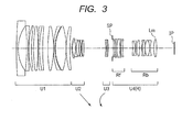
- FIG. 3 illustrates a sectional view of lenses when a zoom lens is set at a wide angle end and focuses on infinity, in Exemplary Embodiment 1 (Numeric Example 1) of the present invention.
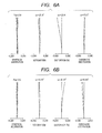
- FIGS. 4A and 4B illustrate views of longitudinal aberrations when zoom lenses are set at a wide angle end and a telephoto end, respectively, and focus on a distance of 5 m, in Numeric Example 1.
- a value of an object distance is such a value that a value in the numeric example which will be described later is expressed by a mm unit.
- the object distance is a distance from a first lens face.
- the object distances in Exemplary Embodiments 2 to 4 are distances from the first lens face, in the same way as in Exemplary Embodiment 1.
- the object distance is a distance from the image plane.
- FIG. 5 illustrates a sectional view of lenses when a zoom lens is set at a wide angle end and focuses on infinity, in Exemplary Embodiment 2 (Numeric Example 2) of the present invention.
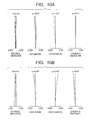
- FIGS. 6A and 6B illustrate views of longitudinal aberrations when zoom lenses are set at a wide angle end and a telephoto end, respectively, and focus on a distance of 5 m, in Numeric Example 2.
- FIG. 7 illustrates a sectional view of lenses when a zoom lens is set at a wide angle end and focuses on infinity, in Exemplary Embodiment 3 (Numeric Example 3) of the present invention.
- FIGS. 8A and 8B illustrate views of longitudinal aberrations when zoom lenses are set at a wide angle end and a telephoto end, respectively, and focus on a distance of 5 m, in Numeric Example 3.
- FIG. 9 illustrates a sectional view of lenses when a zoom lens is set at a wide angle end and focuses on infinity, in Exemplary Embodiment 4 (Numeric Example 4) of the present invention.
- FIGS. 10A and 10B illustrate views of longitudinal aberrations when zoom lenses are set at a wide angle end and a telephoto end, respectively, and focus on a distance of 5 m, in Numeric Example 4.
- FIG. 11 illustrates a sectional view of lenses when a zoom lens is set at a wide angle end and focuses on infinity, in Exemplary Embodiment 5 (Numeric Example 5) of the present invention.
- FIGS. 10A and 10B illustrate views of longitudinal aberrations when zoom lenses are set at a wide angle end and a telephoto end, respectively, and focus on a distance of 5 m, in Numeric Example 4.
- FIG. 11 illustrates a sectional view of lenses when a zoom lens is set at a wide angle end and focuses on infinity, in Exemplary Embodiment 5
- FIG. 12A and 12B illustrate views of longitudinal aberrations when zoom lenses are set at a wide angle end and a telephoto end, respectively, and focus on a distance of 5 m, in Numeric Example 5.
- FIG. 13 illustrates a schematic view of an essential part of an image pickup apparatus of the present invention.
- U1 is a first lens unit having a positive refractive power which does not move during zooming.
- the first lens unit U1 has a lens system for focusing.
- the lens system for focusing is formed of a lens system of the whole or a part of the first lens unit U1, which has a refractive power.
- U2 represents a second lens unit (variator lens unit) having a negative refractive power which moves during zooming.
- This second lens unit U2 moves to an image plane side on the optical axis, and thereby performs zooming from the wide angle end to the telephoto end.
- U3 represents a third lens unit (compensator lens unit) having a negative or positive refractive power which moves during zooming.
- This third lens unit U3 moves on the optical axis in synchronization with the movement of the second lens unit U2, and corrects the variation of the image plane incident to the zooming.
- SP represents an aperture stop.
- U4 represents a fourth lens unit (relay lens unit R) having a positive refractive power which does not move during zooming.
- the aperture stop SP is arranged between the third lens unit U3 and the fourth lens unit U4.
- IP represents an image plane, and corresponds to the image plane of a solid image pickup element (photo-electric conversion element).
- a solid line shows an e-line
- a chain double-dashed line shows a g-line
- a chain line shows a C-line
- a dotted line shows an F-line.
- a dotted line shows a meridional image plane of the e-line
- a solid line shows a sagittal image plane of the e-line.
- a double-dashed line shows a g-line
- a chain line shows a C-line
- a dotted line shows an F-line.
- Fno represents an F number
- ⁇ represents a half angle of view (degree).
- the spherical aberration is drawn on a scale of 0.2 mm
- the astigmatism is drawn on a scale of 0.2 mm
- the distortion is drawn on a scale of 5%
- the lateral chromatic aberration is drawn on a scale of 0.05 mm.
- FIG. 1 is a schematic view illustrating the features of the configuration of the zoom lens in each of the exemplary embodiments.
- the zoom lens in each of the exemplary embodiments includes in order from an object side to an image side: a zooming lens unit LZ having at least two lens units which move during zooming; an aperture stop SP; and a relay lens unit R having a positive refractive power which does not move for zooming.
- a zooming portion LZ corresponds to the second lens unit U2 and the third lens unit U3.
- the relay lens unit R corresponds to the fourth lens unit U4.
- the relay lens unit R may move in the optical axis direction for macro photographing or flange back adjustment.
- An incidence height from an optical axis of an on-axis ray of an i-th lens (thin lens) when having been counted from the object side in paraxial tracking (paraxial light beam tracking) shall be represented by h_i
- an incidence height from an optical axis of an off-axis main light beam of the i-th lens in the paraxial tracking shall be represented by h_bar_i
- a refractive power of the i-th lens in the paraxial tracking shall be represented by ⁇ _i
- an Abbe constant of the material of the i-th lens in the paraxial tracking shall be represented by v_i.
- the paraxial tracking is performed so as to be normalized so that the focal length at the wide angle end of the zoom lens becomes 1.0.
- the e-line is used as a reference wavelength.
- the axial chromatic aberration is proportional to the square of the incidence height h_i
- the lateral chromatic aberration is proportional to the incidence height h_i and the incidence height h_bar_i.
- the incidence height h_bar_i of a lens which is close to the aperture stop SP becomes relatively small, compared to the incidence height h_bar of a lens which is distant from the aperture stop SP. For this reason, in each of the exemplary embodiments, a lens having a low degree of assignment to correct the lateral chromatic aberration is determined to be a front group Rf, and a lens having a high degree of the assignment is determined to be a rear group Rb, with the use of a ratio between the incidence height h_i and the incidence height h_bar_i.
- the incidence height from the optical axis of the on-axis ray of the i-th lens (thin lens) in the paraxial tracking shall be represented by h_i
- the incidence height from the optical axis of the off-axis main light beam of the i-th lens in the paraxial tracking shall be represented by h_bar_i.
- a lens system including a lens face, which satisfies a relationship of h_bar_i/h_i ⁇ 0.06, shall be determined to be the front group Rf, and a lens system that does not include the lens face, which satisfies the relationship shall be determined to be the rear group Rb.
- a positive lens formed of a material having the highest partial dispersion ratio in the rear group Rb shall be determined to be a positive lens Lm. Furthermore, a partial dispersion ratio of the material of the positive lens Lm shall be represented by ⁇ Lm, a distance from the aperture stop SP to the image plane shall be represented by d, and a distance from the aperture stop SP to the positive lens Lm (distance to lens face in object side of positive lens Lm) shall be represented by dLm.
- An average value of Abbe constants of materials of positive lenses contained in the front group Rf shall be represented by vRfp, and an average value of partial dispersion ratios thereof shall be represented by ⁇ Rfp.
- An average value of Abbe constants of materials of negative lenses contained in the front group Rf shall be represented by vRfn, and an average value of partial dispersion ratios thereof shall be represented by ⁇ Rfn.
- the zoom lens satisfies the following conditional expressions: 0.420 ⁇ dLm / d ⁇ 0.710 0.630 ⁇ ⁇ Lm ⁇ 0.690 and 2.16 ⁇ 10 - 3 ⁇ ⁇ Rfn - ⁇ Rfp / ⁇ Rfp - ⁇ Rfn ⁇ 3.10 ⁇ 10 - 3
- the zoom lens is obtained which has a high optical performance in the entire zoom range.
- the zoom lens of each of the exemplary embodiments can further satisfy one or more of the following conditional expressions, in addition to Conditional Expressions (1) to (3).
- the refractive power of the front group Rf shall be represented by ⁇ Rf
- the refractive power of the rear group Rb shall be represented by ⁇ Rb.
- the refractive power of the positive lens Lm shall be represented by ⁇ Lm.
- the zoom lens can satisfy one or more of the following conditional expressions: 2.00 ⁇ 10 - 4 ⁇ ⁇ Rbn - ⁇ Rbp / ⁇ Rbp - ⁇ Rbn ⁇ 1.60 ⁇ 10 - 3 0.17 ⁇ ⁇ Rb / ⁇ Rf ⁇ 0.61 and 0.25 ⁇ ⁇ Lm / ⁇ Rf ⁇ 1.20
- the refractive index in the g-line is represented by Ng
- the refractive index in the F-line is represented by NF
- the refractive index in the d-line is represented by Nd
- the refractive index in the C-line is represented by NC
- Conditional Expressions (1) to (6) specify the dispersion characteristics, the focal length (refractive power), the optical arrangement and the like of the optical materials in the front group Rf and the rear group Rb.
- the correction of the chromatic aberration in the zoom lenses of each of the exemplary embodiments will be described below.
- the zoom lens adequately corrects the lateral chromatic aberration at the wide angle end and the axial chromatic aberration at the telephoto end, it becomes important for the materials to be appropriately selected and for the number of the lenses to be appropriately set.
- the axial chromatic aberration and the lateral chromatic aberration of the F-line with respect to the C-line are defined as the primary spectrum of the axial chromatic aberration, and as the primary spectrum of the lateral chromatic aberration, respectively.
- the axial chromatic aberration and the lateral chromatic aberration of the g-line with respect to the F-line shall be defined as the secondary spectrum of the axial chromatic aberration and the secondary spectrum of the lateral chromatic aberration, respectively.
- the focal length of the whole lens system shall be represented by f
- the image height thereof shall be represented by Y.
- L represents the coefficient of the previously described axial chromatic aberration
- T represents the coefficient of the previously described lateral chromatic aberration.
- Expression (a) and Expression (b) become the coefficients of the chromatic aberration concerning the secondary spectra of the axial chromatic aberration and the lateral chromatic aberration, respectively.
- Expression (c) and Expression (d) express the amounts of the secondary spectra of the axial chromatic aberration and the lateral chromatic aberration, respectively.
- a ratio between the assignment value of each of the lenses for the coefficient of the axial chromatic aberration of the g-line with respect to the F-line and the assignment value of each of the lenses for the coefficient of the lateral chromatic aberration of the g-line with respect to the F-line is determined by a ratio between the incidence height of the on-axis ray and the incidence height of the off-axis light beam.
- a conventional zoom lens has such a tendency that when the primary spectrum of the lateral chromatic aberration at the wide angle end is set at zero, the secondary spectrum of the lateral chromatic aberration results in remaining in positive direction, as is illustrated in FIG. 2 .
- a lens formed of a material having a large absolute value of the difference between the refractive indices of the g-line and the F-line may be configured so as to have an appropriate power, and be arranged at such a position that the ratio between the incidence height of the on-axis ray and the incidence height of the off-axis light beam is appropriate, in the rear group Rb having a high degree of the assignment to correct the lateral chromatic aberration.
- the front group Rf which is close to the aperture stop SP is configured so as to have an appropriate power by appropriate glass materials, and thereby adequately corrects the secondary spectrum of the axial chromatic aberration in the entire zoom range, and the secondary spectrum of the lateral chromatic aberration at the wide angle end.
- the zoom lenses in each of the exemplary embodiments adequately correct the secondary spectrum of the axial chromatic aberration in the entire zoom range, and the secondary spectrum of the lateral chromatic aberration at the wide angle end.
- Conditional Expression (1) specifies a range of the arrangement position of the positive lens Lm in the optical path, and thereby specifies a condition for the zoom lens to achieve an adequate optical performance in the entire zoom range. If a value of Conditional Expression (1) exceeds the upper limit, the secondary spectrum of the lateral chromatic aberration is excessively corrected at the wide angle end, and it becomes difficult for the zoom lens to correct the axial chromatic aberration and the lateral chromatic aberration in the entire zoom range in a well-balanced manner.
- the distance d in Conditional Expression (1) is a distance between the aperture stop and the image plane, which is obtained in the case where a color separation prism, a filter and dummy glass are inserted into the fourth lens unit U4 as glass blocks, by air converting the length of the optical path in which light passes through these glass blocks.
- Conditional Expression (2) specifies a range of the partial dispersion ratio of the material of the positive lens Lm, and thereby specifies a condition for the zoom lens to achieve the adequate optical performance in the entire zoom range. If a value of Conditional Expression (2) exceeds the upper limit, the secondary spectrum of the lateral chromatic aberration is excessively corrected at the wide angle end, and it becomes difficult for the zoom lens to correct the axial chromatic aberration and the lateral chromatic aberration in the entire zoom range in a well-balanced manner. If the value of Conditional Expression (2) exceeds the lower limit, the secondary spectrum of the lateral chromatic aberration is insufficiently corrected at the wide angle end, and it becomes difficult for the zoom lens to adequately correct the chromatic aberration in the entire zoom range.
- Conditional Expression (3) specifies a range of a ratio between an average value of Abbe constants and an average value of partial dispersion ratios of materials of positive lenses and negative lenses which are contained in the front group Rf, and thereby specifies a condition for the zoom lens to achieve the adequate optical performance in the entire zoom range. If a value of Conditional Expression (3) exceeds the upper limit, the secondary spectrum of the axial chromatic aberration is insufficiently corrected at the telephoto end, and it becomes difficult for the zoom lens to adequately correct the chromatic aberration in the entire zoom range.
- Conditional Expression (3) If the value of Conditional Expression (3) exceeds the lower limit, the secondary spectrum of the axial chromatic aberration is excessively corrected at the telephoto end, and it becomes difficult for the zoom lens to correct the axial chromatic aberration and the lateral chromatic aberration in the entire zoom range in a well-balanced manner.
- Conditional Expression (4) specifies a range of a ratio between an average value of Abbe constants and an average value of partial dispersion ratios of materials of positive lenses other than the positive lens Lm and negative lenses, which are contained in the rear group Rb, and thereby specifies a condition for the zoom lens to appropriately correct the secondary spectrum of the lateral chromatic aberration mainly at the wide angle end. If a value of Conditional Expression (4) exceeds the upper limit, the secondary spectrum of the lateral chromatic aberration is insufficiently corrected at the wide angle end, and it becomes difficult for the zoom lens to adequately correct the chromatic aberration in the entire zoom range.
- Conditional Expression (4) If the value of Conditional Expression (4) exceeds the lower limit, the secondary spectrum of the axial chromatic aberration is excessively corrected at the telephoto end, and it becomes difficult for the zoom lens to correct the axial chromatic aberration and the lateral chromatic aberration in the entire zoom range in a well-balanced manner.
- Conditional Expression (5) specifies a range of a ratio between a refractive power of the front group Rf and a refractive power of the rear group Rb, and thereby specifies a condition for the zoom lens to appropriately correct the lateral chromatic aberration at the wide angle end and the axial chromatic aberration at the telephoto end. If a value of Conditional Expression (5) exceeds the upper limit, the secondary spectrum of the lateral chromatic aberration is excessively corrected at the wide angle end, and it becomes difficult for the zoom lens to correct the axial chromatic aberration and the lateral chromatic aberration in the entire zoom range in a well-balanced manner.
- Conditional Expression (5) If the value of Conditional Expression (5) exceeds the lower limit, the secondary spectrum of the axial chromatic aberration is excessively corrected at the telephoto end, and it becomes difficult for the zoom lens to correct the axial chromatic aberration and the lateral chromatic aberration in the entire zoom range in a well-balanced manner.
- Conditional Expression (6) specifies a range of a ratio between a refractive power of the positive lens Lm and a refractive power of the front group Rf, and thereby specifies a condition for the zoom lens to adequately correct the lateral chromatic aberration at the wide angle end. If a value of Conditional Expression (6) exceeds the upper limit, the secondary spectrum of the lateral chromatic aberration is excessively corrected at the wide angle end, and it becomes difficult for the zoom lens to correct the axial chromatic aberration and the lateral chromatic aberration in the entire zoom range in a well-balanced manner.
- Conditional Expression (6) If the value of Conditional Expression (6) exceeds the lower limit, the secondary spectrum of the axial chromatic aberration is excessively corrected at the telephoto end, and it becomes difficult for the zoom lens to correct the axial chromatic aberration and the lateral chromatic aberration in the entire zoom range in a well-balanced manner.
- the range of the numerical values of each of the previously described conditional expressions can be further set in the following way. 0.421 ⁇ dLm / d ⁇ 0.700 0.640 ⁇ ⁇ Lm ⁇ 0.673 2.17 ⁇ 10 - 3 ⁇ ⁇ Rfn - ⁇ Rfp / ⁇ Rfp - ⁇ Rfn ⁇ 3.00 ⁇ 10 - 3 .
- a first lens unit U1 does not move during zooming, and has a positive refractive power.
- the first lens unit U1 moves a lens system of the whole thereof or a part thereof, which has a refractive power, and thereby performs focusing.
- a second lens unit U2 is a lens unit (variator lens unit) having a negative refractive power which moves during zooming. This second lens unit U2 moves to an image plane side on the optical axis, and thereby performs zooming from the wide angle end to the telephoto end.
- a third lens unit U3 is a lens unit (compensator lens unit) having a negative refractive power which moves during zooming.
- This third lens unit U3 moves on the optical axis to the object side so as to form a convex locus in synchronization with the movement of the second lens unit U2, and corrects the variation of the image plane incident to the zooming.
- An aperture stop SP is arranged between the third lens unit U3 and the fourth lens unit U4.
- a fourth lens unit U4 does not move during zooming, and has a positive refractive power for imaging.
- the fourth lens unit U4 corresponds to a 34th surface to a 55th surface in Numeric Example 1, and is formed of the front group Rf of the 34th surface to the 42nd surface and the rear group RB of the 43rd surface to the 55th surface.
- a lens Lm is formed of a material having the highest partial dispersion ratio in the rear group Rb and has a positive refractive power.
- the present exemplary embodiment satisfies any conditional expression, thereby adequately corrects the lateral chromatic aberration at the wide angle end, and adequately corrects the axial chromatic aberration in the entire zoom range.
- the zoom lens in Exemplary Embodiment 2 in FIG. 5 has the same zoom type as that in Exemplary Embodiment 1, which includes the number of the lens units, the refractive power of each of the lens units, and the movement condition of each of the lens units during zooming.
- the fourth lens unit U4 corresponds to a 34th surface to a 55th surface in Numeric Example 2, and is formed of the front group Rf of the 34th surface to the 42nd surface and the rear group RB of the 43rd surface to the 55th surface.
- the lens Lm is formed of a material having the highest partial dispersion ratio in the rear group Rb and has a positive refractive power.
- the present exemplary embodiment satisfies any conditional expression, and thereby shows a similar effect to that in Exemplary Embodiment 1.
- the fourth lens unit U4 corresponds to a 35th surface to a 56th surface in Numeric Example 3, and is formed of the front group Rf of the 35th surface to the 43rd surface and the rear group RB of the 44th surface to the 56th surface.
- the lens Lm is formed of a material having the highest partial dispersion ratio in the rear group Rb and has a positive refractive power.
- the present exemplary embodiment satisfies any conditional expression, and thereby shows a similar effect to that in Exemplary Embodiment 1.
- the fourth lens unit U4 corresponds to a 35th surface to a 56th surface in Numeric Example 4, and is formed of the front group Rf of the 35th surface to the 43rd surface and the rear group RB of the 44th surface to the 56th surface.
- the lens Lm is formed of a material having the highest partial dispersion ratio in the rear group Rb and has a positive refractive power.
- the present exemplary embodiment satisfies any conditional expression, and thereby shows a similar effect to that in Exemplary Embodiment 1.
- a first lens unit U1 does not move during zooming, and has a positive refractive power.
- the first lens unit U1 moves a lens system of the whole thereof or a part thereof, which has a refractive power, and thereby performs focusing.
- the second lens unit U2 is a lens unit (variator lens unit) having a negative refractive power which moves during zooming. This second lens unit U2 moves to an image plane side on the optical axis, and thereby zooms a scene from the wide angle end to the telephoto end.
- the third lens unit U3 is a lens unit (compensator lens unit) having a positive refractive power which moves during zooming.
- This third lens unit U3 moves on the optical axis to the image side so as to form a convex locus in synchronization with the movement of the second lens unit U2, and corrects the variation of the image plane incident to the zooming.
- An aperture stop SP is arranged between the third lens unit U3 and the fourth lens unit U4.
- the fourth lens unit U4 does not move during zooming, and has a positive refractive power for imaging.
- the refractive power of the third lens unit U3 is different from that in Exemplary Embodiment 1.
- the movement locus of the third lens unit U3 during zooming in Exemplary Embodiment 5 is also different from that in Exemplary
- the fourth lens unit U4 corresponds to a 31st surface to a 41st surface in Numeric Example 5, and is formed of the front group Rf of the 31st surface to a 33rd surface and the rear group RB from a 34th surface to the 41st surface.
- the lens Lm is formed of a material having the highest partial dispersion ratio in the rear group Rb and has a positive refractive power.
- the present exemplary embodiment satisfies any conditional expression, and shows a similar effect to that in Exemplary Embodiment 1.
- the positive lens Lm is a lens which is positioned most closely to the image side among lenses in the rear group Rb.
- the front group Rf includes in order from an object side to an image side: a positive lens; a positive lens; a cemented lens of a positive lens and a negative lens which are cemented; and a positive lens.
- the rear group Rb includes in order from an object side to an image side: a cemented lens of a positive lens and a negative lens which are cemented; a positive lens; a cemented lens of a negative lens and a positive lens which are cemented; a cemented lens of a positive lens and a negative lens which are cemented; and a positive lens.
- the front group Rf includes a cemented lens of a negative lens and a positive lens which are cemented in order from an object side to an image side.
- the rear group Rb includes in order from an object side to an image side: a cemented lens of a positive lens and a negative lens which are cemented; a cemented lens of a positive lens and a negative lens which are cemented; and a positive lens.
- FIG. 13 illustrates a schematic view of essential parts of an image pickup apparatus 125 (television camera system) which uses a zoom lens of each exemplary embodiment as an image pickup optical system.
- a zoom lens 101 is any one of the zoom lenses in Exemplary Embodiments 1 to 5.
- a camera body 124 is shown, and the zoom lens 101 is configured so as to be removable from the camera body 124.
- An image pickup apparatus (image pickup system) 125 is structured by the camera 124 and the zoom lens 101 which is mounted thereon.
- the zoom lens 101 and the camera body 124 may also be integrally structured.
- the zoom lens 101 has a first lens unit F, a zooming portion LZ, and a relay lens unit R for imaging (fourth lens unit U4).
- the first lens unit F includes a lens unit for focusing.
- the zooming portion LZ includes: a second lens unit which moves on the optical axis for zooming; and a third lens unit which moves on the optical axis for correcting the variation of the image plane incident to the zooming.
- An aperture stop SP is shown.
- Driving mechanisms 114 and 115 are a helicoid, a cam or the like, and drive the first lens unit F and the zooming portion LZ in the optical axis direction, respectively.
- Motors (driving units) 116 to 118 electrically drive the driving mechanisms 114 and 115 and the aperture stop SP.
- Detectors 119 to 121 are an encoder, a potentiometer, a photosensor or the like, and detect positions of the first lens unit F and the zooming portion LZ on the optical axis, and an aperture diameter of the aperture stop SP.
- a glass block 109 corresponds to an optical filter and color separation prism in the camera body 124.
- a solid image pickup element (photo-electric conversion element) 110 is a CCD sensor, a CMOS sensor or the like, and receives light of a subject image that has been formed by the zoom lens 101.
- CPUs 111 and 122 control various driving of the camera body 124 and the zoom lens body 101.
- Numeric Examples 1 to 5 will be described below which correspond to Exemplary Embodiments 1 to 5 of the present invention, respectively.
- an order i of surfaces from the object side is shown
- a curvature radius ri of the i-th surface from the object side is shown
- a space di between the i-th surface and the (i+1)-th surface both from the object side is shown
- a refractive index ndi and an Abbe constant vdi of an optical member of the i-th surface are shown.
- a back focus BF is shown.
- an optical axis direction is determined to be an X-axis
- a direction perpendicular to the optical axis is determined to be an H-axis
- a traveling direction of light is determined to be positive
- R represents a paraxial radius of curvature
- k represents a conic constant
- A4, A6, A8, A10, A12, A14 and A16 each represent an aspherical coefficient
- an aspherical surface shape is expressed by the following expression.
- the present invention provides a zoom lens which has a high zooming ratio, adequately corrects chromatic aberration in an entire zoom range from a wide angle end to a telephoto end, and has a high optical performance in the entire zoom range; and an image pickup apparatus having the same.
Landscapes
- Physics & Mathematics (AREA)
- General Physics & Mathematics (AREA)
- Optics & Photonics (AREA)
- Nonlinear Science (AREA)
- Lenses (AREA)
Abstract
Description
- The present invention relates to a zoom lens and an image pickup apparatus having the same, which are suitable, for instance, for a broadcasting television camera, a video camera, a digital still camera, a silver-halide film camera and the like.
- In recent years, an image pickup apparatus such as a television camera, a silver halide film camera, a digital camera and a video camera has been desired to be provided with a zoom lens which has a large aperture ratio, a high zooming ratio, and a high optical performance besides. As for the zoom lens having the large aperture ratio and the high zooming ratio, a positive-lead type of four-unit zoom lens is known which has a lens unit having a positive refractive power arranged in the side closest to the object side and includes four lens units as a whole. As for this four-unit zoom lens, a zoom lens is known which has the following lens units in order from an object side to an image side: a first lens unit for focusing; a second lens unit for zooming, which has a negative refractive power; a third lens unit for correcting the variation of an image plane incident to zooming, which has a positive or negative refractive power; and a fourth lens unit for imaging, which has a positive refractive power.
- In this type of four-unit zoom lens, a zoom lens is known which specifies an Abbe constant of a material of a part of the lens in the fourth lens unit, and thereby adequately corrects chromatic aberration, in particular, lateral chromatic aberration, and obtains a high optical performance (
U.S. Patent No. 7885014 ). In addition, in this four-unit zoom lens, a zoom lens is known which employs an optical material having anomalous dispersibility, adequately corrects chromatic aberration, and has a high optical performance and a high zooming ratio (U.S. Patent No. 5831771 andU.S. Patent No. 6825980 ). - The previously described positive-lead type of the four-unit zoom lens comparatively easily achieves the high zooming ratio. However, when the zoom lens acquires the high zooming ratio, the variation of the various aberrations increases, and it becomes difficult to obtain the high optical performance in an entire zoom range. In particular, chromatic aberration such as the lateral chromatic aberration and axial chromatic aberration occurs in many cases.
- In order that the positive-lead type of the four-unit zoom lens adequately corrects the chromatic aberration and obtains the high optical performance while acquiring the high zooming ratio, it is important, for instance, to appropriately set the configuration of the fourth lens unit for imaging. If the configuration of the fourth lens unit is not appropriately set, it becomes difficult to correct the lateral chromatic aberration and the axial chromatic aberration, and to obtain the high zooming ratio and the high optical performance in an entire zoom range.
- An object of the present invention is to provide a zoom lens which has a high zooming ratio, adequately corrects chromatic aberration in an entire zoom range from a wide angle end to a telephoto end, and has a high optical performance in the entire zoom range, and to provide an image pickup apparatus having the same.
- A zoom lens of the present invention includes in order from an object side to an image side: a first lens unit having a positive refractive power which does not move for zooming; a second lens unit having a negative refractive power which moves during zooming; a third lens unit having a positive or negative refractive power which moves during zooming; an aperture stop; and a fourth lens unit having a positive refractive power which does not move for zooming, wherein in the fourth lens unit, when an incidence height from an optical axis of an on-axis ray of an i-th lens (thin lens) in paraxial tracking is represented by h_i, an incidence height from an optical axis of an off-axis main light beam of the i-th lens in the paraxial tracking is represented by h_bar_i, a lens system including a lens face which satisfies a relationship of h_bar_i/h_i ≤ 0.06,
out of lenses in an optical path from the aperture stop to an image plane, is referred to as a front group, and a lens system other than the front group is referred to as a rear group, and
when a partial dispersion ratio of a material_of a positive lens Lm formed of a material having a highest partial dispersion ratio, which is contained in the rear group, is represented by θLm, a distance from the aperture stop to the image plane is represented by d, a distance from the aperture stop to the positive lens Lm is represented by dLm, an average value of Abbe constants of materials of positive lenses contained in the front group is represented by vRfp, an average value of partial dispersion ratios thereof is represented by θRfp, an average value of Abbe constants of materials of negative lenses contained in the front group is represented by vRfn, and an average value of partial dispersion ratios thereof is represented by θRfn, the zoom lens satisfies following conditional expressions:

and
- Further features of the present invention will become apparent from the following description of exemplary embodiments with reference to the attached drawings.
-
-
FIG. 1 illustrates a schematic view of a configuration of a zoom lens of the present invention. -
FIG. 2 illustrates an explanatory drawing of a secondary spectrum of lateral chromatic aberration. -
FIG. 3 illustrates a sectional view of lenses when a zoom lens is set at a wide angle end and focuses on infinity, in Exemplary Embodiment 1 of the present invention. -
FIG. 4A illustrates a view of longitudinal aberration when a zoom lens is set at a wide angle end and focuses on a distance of 5 m, in Numeric Example 1. -
FIG. 4B illustrates a view of longitudinal aberration when the zoom lens is set at a telephoto end and focuses on the distance of 5 m, in Numeric Example 1. -
FIG. 5 illustrates a sectional view of lenses when a zoom lens is set at a wide angle end and focuses on infinity, in Exemplary Embodiment 2 of the present invention. -
FIG. 6A illustrates a view of longitudinal aberration when the zoom lens is set at a wide angle end and focuses on a distance of 5 m, in Numeric Example 2. -
FIG. 6B illustrates a view of longitudinal aberration when the zoom lens is set at a telephoto end and focuses on the distance of 5 m, in Numeric Example 2. -
FIG. 7 illustrates a sectional view of lenses when a zoom lens is set at a wide angle end and focuses on infinity, in Exemplary Embodiment 3 of the present invention. -
FIG. 8A illustrates a view of longitudinal aberration when the zoom lens is set at a wide angle end and focuses on a distance of 5 m, in Numeric Example 3. -
FIG. 8B illustrates a view of longitudinal aberration when the zoom lens is set at a telephoto end and focuses on the distance of 5 m, in Numeric Example 3. -
FIG. 9 illustrates a sectional view of lenses when a zoom lens is set at a wide angle end and focuses on infinity, in Exemplary Embodiment 4 of the present invention. -
FIG. 10A illustrates a view of longitudinal aberration when the zoom lens is set at a wide angle end and focuses on a distance of 5 m, in Numeric Example 4. -
FIG. 10B illustrates a view of longitudinal aberration when the zoom lens is set at a telephoto end and focuses on the distance of 5 m, in Numeric Example 4. -
FIG. 11 illustrates a sectional view of lenses when a zoom lens is set at a wide angle end and focuses on infinity, in Exemplary Embodiment 5 of the present invention. -
FIG. 12A illustrates a view of longitudinal aberration when the zoom lens is set at a wide angle end and focuses on a distance of 5 m, in Numeric Example 5. -
FIG. 12B illustrates a view of longitudinal aberration when the zoom lens is set at a telephoto end and focuses on the distance of 5 m, in Numeric Example 5. -
FIG. 13 illustrates a schematic view of an essential part of an image pickup apparatus of the present invention. - Preferred embodiments of the present invention will now be described in detail in accordance with the accompanying drawings.
- Embodiments according to the present invention will be described in detail below with reference to the attached drawings. A zoom lens of the present invention includes in order from an object side to an image side: a first lens unit having a positive refractive power which does not move for zooming; a second lens unit having a negative refractive power which moves during zooming; furthermore, a third lens unit having a positive or negative refractive power which moves during zooming; an aperture stop; and a fourth lens unit having a positive refractive power which does not move for zooming.
-
FIG. 1 illustrates a schematic view of a zoom lens of the present invention.FIG. 2 illustrates an explanatory drawing of a secondary spectrum of lateral chromatic aberration.FIG. 3 illustrates a sectional view of lenses when a zoom lens is set at a wide angle end and focuses on infinity, in Exemplary Embodiment 1 (Numeric Example 1) of the present invention.FIGS. 4A and 4B illustrate views of longitudinal aberrations when zoom lenses are set at a wide angle end and a telephoto end, respectively, and focus on a distance of 5 m, in Numeric Example 1. However, a value of an object distance is such a value that a value in the numeric example which will be described later is expressed by a mm unit. The object distance is a distance from a first lens face. The object distances in Exemplary Embodiments 2 to 4 are distances from the first lens face, in the same way as in Exemplary Embodiment 1. In Exemplary Embodiment 5, the object distance is a distance from the image plane. -
FIG. 5 illustrates a sectional view of lenses when a zoom lens is set at a wide angle end and focuses on infinity, in Exemplary Embodiment 2 (Numeric Example 2) of the present invention.FIGS. 6A and 6B illustrate views of longitudinal aberrations when zoom lenses are set at a wide angle end and a telephoto end, respectively, and focus on a distance of 5 m, in Numeric Example 2.FIG. 7 illustrates a sectional view of lenses when a zoom lens is set at a wide angle end and focuses on infinity, in Exemplary Embodiment 3 (Numeric Example 3) of the present invention.FIGS. 8A and 8B illustrate views of longitudinal aberrations when zoom lenses are set at a wide angle end and a telephoto end, respectively, and focus on a distance of 5 m, in Numeric Example 3. -
FIG. 9 illustrates a sectional view of lenses when a zoom lens is set at a wide angle end and focuses on infinity, in Exemplary Embodiment 4 (Numeric Example 4) of the present invention.FIGS. 10A and 10B illustrate views of longitudinal aberrations when zoom lenses are set at a wide angle end and a telephoto end, respectively, and focus on a distance of 5 m, in Numeric Example 4.FIG. 11 illustrates a sectional view of lenses when a zoom lens is set at a wide angle end and focuses on infinity, in Exemplary Embodiment 5 (Numeric Example 5) of the present invention.FIGS. 12A and 12B illustrate views of longitudinal aberrations when zoom lenses are set at a wide angle end and a telephoto end, respectively, and focus on a distance of 5 m, in Numeric Example 5.FIG. 13 illustrates a schematic view of an essential part of an image pickup apparatus of the present invention. - In the sectional views of the lenses, U1 is a first lens unit having a positive refractive power which does not move during zooming. The first lens unit U1 has a lens system for focusing. The lens system for focusing is formed of a lens system of the whole or a part of the first lens unit U1, which has a refractive power.
- U2 represents a second lens unit (variator lens unit) having a negative refractive power which moves during zooming. This second lens unit U2 moves to an image plane side on the optical axis, and thereby performs zooming from the wide angle end to the telephoto end. U3 represents a third lens unit (compensator lens unit) having a negative or positive refractive power which moves during zooming. This third lens unit U3 moves on the optical axis in synchronization with the movement of the second lens unit U2, and corrects the variation of the image plane incident to the zooming. SP represents an aperture stop. U4 represents a fourth lens unit (relay lens unit R) having a positive refractive power which does not move during zooming.
- The aperture stop SP is arranged between the third lens unit U3 and the fourth lens unit U4. IP represents an image plane, and corresponds to the image plane of a solid image pickup element (photo-electric conversion element). In the views of the spherical aberration, a solid line shows an e-line, a chain double-dashed line shows a g-line, a chain line shows a C-line, and a dotted line shows an F-line. In the astigmatism, a dotted line shows a meridional image plane of the e-line, and a solid line shows a sagittal image plane of the e-line. In the lateral chromatic aberration, a double-dashed line shows a g-line, a chain line shows a C-line, and a dotted line shows an F-line. Fno represents an F number, and ω represents a half angle of view (degree).
- In the views of the aberration, the spherical aberration is drawn on a scale of 0.2 mm, the astigmatism is drawn on a scale of 0.2 mm, the distortion is drawn on a scale of 5%, and the lateral chromatic aberration is drawn on a scale of 0.05 mm.
- Firstly, the features of the configurations of lenses in the zoom lens in each of the exemplary embodiments will be described below.
FIG. 1 is a schematic view illustrating the features of the configuration of the zoom lens in each of the exemplary embodiments. The zoom lens in each of the exemplary embodiments includes in order from an object side to an image side: a zooming lens unit LZ having at least two lens units which move during zooming; an aperture stop SP; and a relay lens unit R having a positive refractive power which does not move for zooming. Here, a zooming portion LZ corresponds to the second lens unit U2 and the third lens unit U3. The relay lens unit R corresponds to the fourth lens unit U4. Incidentally, the relay lens unit R may move in the optical axis direction for macro photographing or flange back adjustment. - The definitions of the front group Rf and the rear group Rb in each of the exemplary embodiments will be described later. An incidence height from an optical axis of an on-axis ray of an i-th lens (thin lens) when having been counted from the object side in paraxial tracking (paraxial light beam tracking) shall be represented by h_i, and an incidence height from an optical axis of an off-axis main light beam of the i-th lens in the paraxial tracking shall be represented by h_bar_i. In addition, a refractive power of the i-th lens in the paraxial tracking shall be represented by φ_i, and an Abbe constant of the material of the i-th lens in the paraxial tracking shall be represented by v_i. The paraxial tracking is performed so as to be normalized so that the focal length at the wide angle end of the zoom lens becomes 1.0. The e-line is used as a reference wavelength.
- At this time, a coefficient L of axial chromatic aberration of the zoom lens and a coefficient T of lateral chromatic aberration thereof can be expressed as follows:

and
- From Expression (a) and Expression (b), the axial chromatic aberration is proportional to the square of the incidence height h_i, and the lateral chromatic aberration is proportional to the incidence height h_i and the incidence height h_bar_i.
- The incidence height h_bar_i of a lens which is close to the aperture stop SP becomes relatively small, compared to the incidence height h_bar of a lens which is distant from the aperture stop SP. For this reason, in each of the exemplary embodiments, a lens having a low degree of assignment to correct the lateral chromatic aberration is determined to be a front group Rf, and a lens having a high degree of the assignment is determined to be a rear group Rb, with the use of a ratio between the incidence height h_i and the incidence height h_bar_i.
- Next, the features of the zoom lens of each of the exemplary embodiments will be described below. In the fourth lens unit U4, the incidence height from the optical axis of the on-axis ray of the i-th lens (thin lens) in the paraxial tracking shall be represented by h_i, and the incidence height from the optical axis of the off-axis main light beam of the i-th lens in the paraxial tracking shall be represented by h_bar_i. In the fourth lens unit U4 which is positioned in the optical path from the aperture stop SP to the image plane, a lens system including a lens face, which satisfies a relationship of h_bar_i/h_i ≤ 0.06,
shall be determined to be the front group Rf, and a lens system that does not include the lens face, which satisfies the relationship shall be determined to be the rear group Rb. - A positive lens formed of a material having the highest partial dispersion ratio in the rear group Rb shall be determined to be a positive lens Lm. Furthermore, a partial dispersion ratio of the material of the positive lens Lm shall be represented by θLm, a distance from the aperture stop SP to the image plane shall be represented by d, and a distance from the aperture stop SP to the positive lens Lm (distance to lens face in object side of positive lens Lm) shall be represented by dLm.
- An average value of Abbe constants of materials of positive lenses contained in the front group Rf shall be represented by vRfp, and an average value of partial dispersion ratios thereof shall be represented by θRfp. An average value of Abbe constants of materials of negative lenses contained in the front group Rf shall be represented by vRfn, and an average value of partial dispersion ratios thereof shall be represented by θRfn. At this time, the zoom lens satisfies the following conditional expressions:


- By being configured in this way, the zoom lens is obtained which has a high optical performance in the entire zoom range.
- The zoom lens of each of the exemplary embodiments can further satisfy one or more of the following conditional expressions, in addition to Conditional Expressions (1) to (3). An average value of Abbe constants of materials of positive lenses other than the positive lens Lm, which are contained in the rear group Rb, shall be represented by vRbp, an average value of partial dispersion ratios thereof shall be represented by θRbp, an average value of Abbe constants of materials of negative lenses contained in the rear group Rb shall be represented by vRbn, and an average value of partial dispersion ratios thereof shall be represented by θRbn. The refractive power of the front group Rf shall be represented by φRf, and the refractive power of the rear group Rb shall be represented by φRb. The refractive power of the positive lens Lm shall be represented by φLm. At this time, the zoom lens can satisfy one or more of the following conditional expressions:


and
- Here, when the refractive index in the g-line is represented by Ng, the refractive index in the F-line is represented by NF, the refractive index in the d-line is represented by Nd, and the refractive index in the C-line is represented by NC, the Abbe constant ν of the material and the partial dispersion ratio θ satisfy the following relationships:


- Conditional Expressions (1) to (6) specify the dispersion characteristics, the focal length (refractive power), the optical arrangement and the like of the optical materials in the front group Rf and the rear group Rb. By satisfying these conditional expressions, the zoom lens adequately corrects the secondary spectrum of the lateral chromatic aberration at the wide angle end, and the axial chromatic aberration at the telephoto end, and obtains a high optical performance in the entire zoom range.
- The correction of the chromatic aberration in the zoom lenses of each of the exemplary embodiments will be described below. In order to obtain a high optical performance in the entire zoom range of the zoom lens, it becomes important for the zoom lens to adequately correct the lateral chromatic aberration at the wide angle end and the axial chromatic aberration at the telephoto end. In order that the zoom lens adequately corrects the lateral chromatic aberration at the wide angle end and the axial chromatic aberration at the telephoto end, it becomes important for the materials to be appropriately selected and for the number of the lenses to be appropriately set.
- Here, the axial chromatic aberration and the lateral chromatic aberration of the F-line with respect to the C-line are defined as the primary spectrum of the axial chromatic aberration, and as the primary spectrum of the lateral chromatic aberration, respectively. In addition, the axial chromatic aberration and the lateral chromatic aberration of the g-line with respect to the F-line, which remain after the respective primary spectra have been corrected to zero, shall be defined as the secondary spectrum of the axial chromatic aberration and the secondary spectrum of the lateral chromatic aberration, respectively. The amount Δf of the axial chromatic aberration of the whole lens system and the amount ΔY of the lateral chromatic aberration thereof are given by the following Expression (c) and Expression (d):

and
- However, the focal length of the whole lens system shall be represented by f, and the image height thereof shall be represented by Y. L represents the coefficient of the previously described axial chromatic aberration, and T represents the coefficient of the previously described lateral chromatic aberration.
- Now, the partial dispersion Ng-NF of the Abbe constant ν_i which is used in Expression (a) and Expression (b) will be considered. Expression (a) and Expression (b) become the coefficients of the chromatic aberration concerning the secondary spectra of the axial chromatic aberration and the lateral chromatic aberration, respectively. Expression (c) and Expression (d) express the amounts of the secondary spectra of the axial chromatic aberration and the lateral chromatic aberration, respectively. From Expression (a) and Expression (c), the assignment value of each of the lenses for the secondary spectrum of the axial chromatic aberration increases in proportion to the square of the incidence height of the on-axis ray, the power of the lens, and a difference between the refractive indices of the g-line and the F-line.
- From Expression (b) and Expression (d), the assignment value of each of the lenses for the secondary spectrum of the lateral chromatic aberration increases in proportion to the incidence height of the on-axis ray, the incidence height of the off-axis light beam, the power of the lens, and a difference between the refractive indices of the g-line and the F-line. Furthermore, from Expression (a) and Expression (b), a ratio between the assignment value of each of the lenses for the coefficient of the axial chromatic aberration of the g-line with respect to the F-line and the assignment value of each of the lenses for the coefficient of the lateral chromatic aberration of the g-line with respect to the F-line is determined by a ratio between the incidence height of the on-axis ray and the incidence height of the off-axis light beam. A conventional zoom lens has such a tendency that when the primary spectrum of the lateral chromatic aberration at the wide angle end is set at zero, the secondary spectrum of the lateral chromatic aberration results in remaining in positive direction, as is illustrated in
FIG. 2 . - In order to correct the secondary spectrum, a lens formed of a material having a large absolute value of the difference between the refractive indices of the g-line and the F-line may be configured so as to have an appropriate power, and be arranged at such a position that the ratio between the incidence height of the on-axis ray and the incidence height of the off-axis light beam is appropriate, in the rear group Rb having a high degree of the assignment to correct the lateral chromatic aberration. Thereby, it is facilitated for the zoom lens to correct the secondary spectrum of the lateral chromatic aberration at the wide angle end. In addition, the front group Rf which is close to the aperture stop SP is configured so as to have an appropriate power by appropriate glass materials, and thereby adequately corrects the secondary spectrum of the axial chromatic aberration in the entire zoom range, and the secondary spectrum of the lateral chromatic aberration at the wide angle end.
- The zoom lenses in each of the exemplary embodiments adequately correct the secondary spectrum of the axial chromatic aberration in the entire zoom range, and the secondary spectrum of the lateral chromatic aberration at the wide angle end.
- Next, the technical meaning of the previously described conditional expressions will be described. Conditional Expression (1) specifies a range of the arrangement position of the positive lens Lm in the optical path, and thereby specifies a condition for the zoom lens to achieve an adequate optical performance in the entire zoom range. If a value of Conditional Expression (1) exceeds the upper limit, the secondary spectrum of the lateral chromatic aberration is excessively corrected at the wide angle end, and it becomes difficult for the zoom lens to correct the axial chromatic aberration and the lateral chromatic aberration in the entire zoom range in a well-balanced manner.
- If the value of Conditional Expression (1) exceeds the lower limit, the secondary spectrum of the lateral chromatic aberration is insufficiently corrected, and it becomes difficult for the zoom lens to adequately correct the chromatic aberration in the entire zoom range. The distance d in Conditional Expression (1) is a distance between the aperture stop and the image plane, which is obtained in the case where a color separation prism, a filter and dummy glass are inserted into the fourth lens unit U4 as glass blocks, by air converting the length of the optical path in which light passes through these glass blocks.
- Conditional Expression (2) specifies a range of the partial dispersion ratio of the material of the positive lens Lm, and thereby specifies a condition for the zoom lens to achieve the adequate optical performance in the entire zoom range. If a value of Conditional Expression (2) exceeds the upper limit, the secondary spectrum of the lateral chromatic aberration is excessively corrected at the wide angle end, and it becomes difficult for the zoom lens to correct the axial chromatic aberration and the lateral chromatic aberration in the entire zoom range in a well-balanced manner. If the value of Conditional Expression (2) exceeds the lower limit, the secondary spectrum of the lateral chromatic aberration is insufficiently corrected at the wide angle end, and it becomes difficult for the zoom lens to adequately correct the chromatic aberration in the entire zoom range.
- Conditional Expression (3) specifies a range of a ratio between an average value of Abbe constants and an average value of partial dispersion ratios of materials of positive lenses and negative lenses which are contained in the front group Rf, and thereby specifies a condition for the zoom lens to achieve the adequate optical performance in the entire zoom range. If a value of Conditional Expression (3) exceeds the upper limit, the secondary spectrum of the axial chromatic aberration is insufficiently corrected at the telephoto end, and it becomes difficult for the zoom lens to adequately correct the chromatic aberration in the entire zoom range. If the value of Conditional Expression (3) exceeds the lower limit, the secondary spectrum of the axial chromatic aberration is excessively corrected at the telephoto end, and it becomes difficult for the zoom lens to correct the axial chromatic aberration and the lateral chromatic aberration in the entire zoom range in a well-balanced manner.
- Conditional Expression (4) specifies a range of a ratio between an average value of Abbe constants and an average value of partial dispersion ratios of materials of positive lenses other than the positive lens Lm and negative lenses, which are contained in the rear group Rb, and thereby specifies a condition for the zoom lens to appropriately correct the secondary spectrum of the lateral chromatic aberration mainly at the wide angle end. If a value of Conditional Expression (4) exceeds the upper limit, the secondary spectrum of the lateral chromatic aberration is insufficiently corrected at the wide angle end, and it becomes difficult for the zoom lens to adequately correct the chromatic aberration in the entire zoom range. If the value of Conditional Expression (4) exceeds the lower limit, the secondary spectrum of the axial chromatic aberration is excessively corrected at the telephoto end, and it becomes difficult for the zoom lens to correct the axial chromatic aberration and the lateral chromatic aberration in the entire zoom range in a well-balanced manner.
- Conditional Expression (5) specifies a range of a ratio between a refractive power of the front group Rf and a refractive power of the rear group Rb, and thereby specifies a condition for the zoom lens to appropriately correct the lateral chromatic aberration at the wide angle end and the axial chromatic aberration at the telephoto end. If a value of Conditional Expression (5) exceeds the upper limit, the secondary spectrum of the lateral chromatic aberration is excessively corrected at the wide angle end, and it becomes difficult for the zoom lens to correct the axial chromatic aberration and the lateral chromatic aberration in the entire zoom range in a well-balanced manner. If the value of Conditional Expression (5) exceeds the lower limit, the secondary spectrum of the axial chromatic aberration is excessively corrected at the telephoto end, and it becomes difficult for the zoom lens to correct the axial chromatic aberration and the lateral chromatic aberration in the entire zoom range in a well-balanced manner.
- Conditional Expression (6) specifies a range of a ratio between a refractive power of the positive lens Lm and a refractive power of the front group Rf, and thereby specifies a condition for the zoom lens to adequately correct the lateral chromatic aberration at the wide angle end. If a value of Conditional Expression (6) exceeds the upper limit, the secondary spectrum of the lateral chromatic aberration is excessively corrected at the wide angle end, and it becomes difficult for the zoom lens to correct the axial chromatic aberration and the lateral chromatic aberration in the entire zoom range in a well-balanced manner. If the value of Conditional Expression (6) exceeds the lower limit, the secondary spectrum of the axial chromatic aberration is excessively corrected at the telephoto end, and it becomes difficult for the zoom lens to correct the axial chromatic aberration and the lateral chromatic aberration in the entire zoom range in a well-balanced manner. The range of the numerical values of each of the previously described conditional expressions can be further set in the following way.




- Next, the features of each of the exemplary embodiments will be described.
- In the sectional view of the lenses of Exemplary Embodiment 1 in
FIG. 3 , a first lens unit U1 does not move during zooming, and has a positive refractive power. The first lens unit U1 moves a lens system of the whole thereof or a part thereof, which has a refractive power, and thereby performs focusing. A second lens unit U2 is a lens unit (variator lens unit) having a negative refractive power which moves during zooming. This second lens unit U2 moves to an image plane side on the optical axis, and thereby performs zooming from the wide angle end to the telephoto end. - A third lens unit U3 is a lens unit (compensator lens unit) having a negative refractive power which moves during zooming. This third lens unit U3 moves on the optical axis to the object side so as to form a convex locus in synchronization with the movement of the second lens unit U2, and corrects the variation of the image plane incident to the zooming. An aperture stop SP is arranged between the third lens unit U3 and the fourth lens unit U4. A fourth lens unit U4 does not move during zooming, and has a positive refractive power for imaging.
- Next, the configuration of the lenses of the fourth lens unit U4 in the present exemplary embodiment will be described. The fourth lens unit U4 corresponds to a 34th surface to a 55th surface in Numeric Example 1, and is formed of the front group Rf of the 34th surface to the 42nd surface and the rear group RB of the 43rd surface to the 55th surface. A lens Lm is formed of a material having the highest partial dispersion ratio in the rear group Rb and has a positive refractive power.
- The present exemplary embodiment satisfies any conditional expression, thereby adequately corrects the lateral chromatic aberration at the wide angle end, and adequately corrects the axial chromatic aberration in the entire zoom range.
- The zoom lens in Exemplary Embodiment 2 in
FIG. 5 has the same zoom type as that in Exemplary Embodiment 1, which includes the number of the lens units, the refractive power of each of the lens units, and the movement condition of each of the lens units during zooming. - Next, the configuration of the lenses in the fourth lens unit U4 in the present exemplary embodiment will be described. The fourth lens unit U4 corresponds to a 34th surface to a 55th surface in Numeric Example 2, and is formed of the front group Rf of the 34th surface to the 42nd surface and the rear group RB of the 43rd surface to the 55th surface. The lens Lm is formed of a material having the highest partial dispersion ratio in the rear group Rb and has a positive refractive power.
- The present exemplary embodiment satisfies any conditional expression, and thereby shows a similar effect to that in Exemplary Embodiment 1.
- The zoom type of Exemplary Embodiment 3 in
FIG. 7 is the same as that in Exemplary Embodiment 1. - Next, the configuration of the lenses in the fourth lens unit U4 in the present exemplary embodiment will be described. The fourth lens unit U4 corresponds to a 35th surface to a 56th surface in Numeric Example 3, and is formed of the front group Rf of the 35th surface to the 43rd surface and the rear group RB of the 44th surface to the 56th surface. The lens Lm is formed of a material having the highest partial dispersion ratio in the rear group Rb and has a positive refractive power.
- The present exemplary embodiment satisfies any conditional expression, and thereby shows a similar effect to that in Exemplary Embodiment 1.
- The zoom type of Exemplary Embodiment 4 in
FIG. 9 is the same as that in Exemplary Embodiment 1. - Next, the configuration of the lenses in the fourth lens unit U4 in the present exemplary embodiment will be described. The fourth lens unit U4 corresponds to a 35th surface to a 56th surface in Numeric Example 4, and is formed of the front group Rf of the 35th surface to the 43rd surface and the rear group RB of the 44th surface to the 56th surface. The lens Lm is formed of a material having the highest partial dispersion ratio in the rear group Rb and has a positive refractive power.
- The present exemplary embodiment satisfies any conditional expression, and thereby shows a similar effect to that in Exemplary Embodiment 1.
- In the sectional view of the lenses of Exemplary Embodiment 5 in
FIG. 11 , a first lens unit U1 does not move during zooming, and has a positive refractive power. The first lens unit U1 moves a lens system of the whole thereof or a part thereof, which has a refractive power, and thereby performs focusing. The second lens unit U2 is a lens unit (variator lens unit) having a negative refractive power which moves during zooming. This second lens unit U2 moves to an image plane side on the optical axis, and thereby zooms a scene from the wide angle end to the telephoto end. - The third lens unit U3 is a lens unit (compensator lens unit) having a positive refractive power which moves during zooming. This third lens unit U3 moves on the optical axis to the image side so as to form a convex locus in synchronization with the movement of the second lens unit U2, and corrects the variation of the image plane incident to the zooming. An aperture stop SP is arranged between the third lens unit U3 and the fourth lens unit U4. The fourth lens unit U4 does not move during zooming, and has a positive refractive power for imaging.
- In Exemplary Embodiment 5, the refractive power of the third lens unit U3 is different from that in Exemplary Embodiment 1. In addition, the movement locus of the third lens unit U3 during zooming in Exemplary Embodiment 5 is also different from that in Exemplary
- Next, the configuration of the lenses in the fourth lens unit U4 in the present exemplary embodiment will be described. The fourth lens unit U4 corresponds to a 31st surface to a 41st surface in Numeric Example 5, and is formed of the front group Rf of the 31st surface to a 33rd surface and the rear group RB from a 34th surface to the 41st surface. The lens Lm is formed of a material having the highest partial dispersion ratio in the rear group Rb and has a positive refractive power. The present exemplary embodiment satisfies any conditional expression, and shows a similar effect to that in Exemplary Embodiment 1.
- In Exemplary Embodiments 1, 4 and 5, the positive lens Lm is a lens which is positioned most closely to the image side among lenses in the rear group Rb.
- In Exemplary Embodiments 1 to 4, the front group Rf includes in order from an object side to an image side: a positive lens; a positive lens; a cemented lens of a positive lens and a negative lens which are cemented; and a positive lens. The rear group Rb includes in order from an object side to an image side: a cemented lens of a positive lens and a negative lens which are cemented; a positive lens; a cemented lens of a negative lens and a positive lens which are cemented; a cemented lens of a positive lens and a negative lens which are cemented; and a positive lens.
- In Exemplary Embodiment 5, the front group Rf includes a cemented lens of a negative lens and a positive lens which are cemented in order from an object side to an image side. The rear group Rb includes in order from an object side to an image side: a cemented lens of a positive lens and a negative lens which are cemented; a cemented lens of a positive lens and a negative lens which are cemented; and a positive lens.
-
FIG. 13 illustrates a schematic view of essential parts of an image pickup apparatus 125 (television camera system) which uses a zoom lens of each exemplary embodiment as an image pickup optical system. InFIG. 13 , azoom lens 101 is any one of the zoom lenses in Exemplary Embodiments 1 to 5. Acamera body 124 is shown, and thezoom lens 101 is configured so as to be removable from thecamera body 124. An image pickup apparatus (image pickup system) 125 is structured by thecamera 124 and thezoom lens 101 which is mounted thereon. In addition, thezoom lens 101 and thecamera body 124 may also be integrally structured. - The
zoom lens 101 has a first lens unit F, a zooming portion LZ, and a relay lens unit R for imaging (fourth lens unit U4). The first lens unit F includes a lens unit for focusing. The zooming portion LZ includes: a second lens unit which moves on the optical axis for zooming; and a third lens unit which moves on the optical axis for correcting the variation of the image plane incident to the zooming. An aperture stop SP is shown. - Driving
mechanisms mechanisms Detectors 119 to 121 are an encoder, a potentiometer, a photosensor or the like, and detect positions of the first lens unit F and the zooming portion LZ on the optical axis, and an aperture diameter of the aperture stop SP. - In the
camera body 124, aglass block 109 corresponds to an optical filter and color separation prism in thecamera body 124. A solid image pickup element (photo-electric conversion element) 110 is a CCD sensor, a CMOS sensor or the like, and receives light of a subject image that has been formed by thezoom lens 101. In addition,CPUs camera body 124 and thezoom lens body 101. - Thus, when the zoom lens according to the present invention is applied to a television camera, an image pickup apparatus having a high optical performance is achieved.
- Numeric Examples 1 to 5 will be described below which correspond to Exemplary Embodiments 1 to 5 of the present invention, respectively. In each of the numeric examples, an order i of surfaces from the object side is shown, a curvature radius ri of the i-th surface from the object side is shown, a space di between the i-th surface and the (i+1)-th surface both from the object side is shown, and a refractive index ndi and an Abbe constant vdi of an optical member of the i-th surface are shown. A back focus BF is shown. When an optical axis direction is determined to be an X-axis, a direction perpendicular to the optical axis is determined to be an H-axis, a traveling direction of light is determined to be positive, R represents a paraxial radius of curvature, k represents a conic constant, and A4, A6, A8, A10, A12, A14 and A16 each represent an aspherical coefficient, an aspherical surface shape is expressed by the following expression.

- The aspherical surface shape is expressed by the above expression. In addition, for instance, "e-Z" means "×10-z". A symbol * shows an aspherical surface. Correspondence between each of the exemplary embodiments and the previously described conditional expressions is illustrated in Table 1.
-
Unit mm Surface data Surface number r d nd νd Effective diameter Partial dispersion ratio 1* 911.475 4.5 1.7725 49.6 118.67 0.5521 2 70.091 25.21 96.56 3 -298.958 4.2 1.6516 58.5 96.01 0.5426 4 479.689 1 95.25 5 139.728 7.86 1.80809 22.8 96.27 0.6307 6 249.448 6.04 94.9 7 246.156 12.57 1.48749 70.2 95.07 0.5300 8* -392.58 0.2 94.63 9 335.038 3.7 1.801 35 94.08 0.5863 10 167.705 9.41 1.43875 94.9 94.23 0.5343 11 388.693 14.73 94.39 12 287.452 15.83 1.497 81.5 94.84 0.5374 13 -167.848 0.2 95.03 14 126.264 3.5 1.801 35 93.59 0.5863 15 75.512 1.7 92.55 16 77.716 30.51 1.43875 94.9 93.49 0.5343 17 -133.309 0.2 94.21 18 140.368 10.02 1.618 63.3 91.96 0.5441 19 324.842 (Variable) 90.96 20 50.717 2 1.7725 49.6 41.93 0.5521 21 33.561 9.07 37.69 22 -69.598 2 1.60311 60.6 36.44 0.5414 23 50.664 7.79 34 24 -63.254 5.39 1.72047 34.7 34.25 0.5834 25 -35.905 1.15 34.73 26 -36.198 2 1.618 63.3 34.59 0.5441 27 602.025 0.2 34.26 28 98.362 5.22 1.72047 34.7 34.26 0.5834 29 -203.314 (Variable) 33.75 30 -80.519 1.7 1.7725 49.6 33.78 0.5521 31 148.442 4.28 1.84666 23.8 35.06 0.6205 32 -711.419 (Variable) 35.84 33 (Aperture) ∞ 2.7 37.03 34 -276.05 4.37 1.64 60.1 37.94 0.5370 35 -85.467 0.2 38.84 36 232.219 4.85 1.64 60.1 39.6 0.5370 37 -284.206 0.2 39.84 38 88.258 8.99 1.64 60.1 39.93 0.5370 39 -67.152 1.94 1.68893 31.1 39.32 0.6003 40 591.515 0.2 38.6 41 62.22 5.3 1.64 60.1 38.05 0.5370 42 84.322 28.82 36.48 43 -187.346 6.96 1.84666 23.8 30.22 0.6205 44 -32.033 1.7 1.883 40.8 30.48 0.5667 45 76.406 2.99 31.1 46 40.475 8.18 1.48749 70.2 34.02 0.5300 47 -97.483 6.41 34.14 48 200.529 1.7 1.8061 33.3 33.15 0.5881 49 36.319 7.79 1.48749 70.2 32.48 0.5300 50 -146.099 0.2 32.62 51 42.715 12.89 1.48749 70.2 32.44 0.5300 52 -30.343 1.7 1.78472 25.7 30.85 0.6161 53 40.764 10.04 30.58 54 61.976 7.88 1.80809 22.8 37.12 0.6307 55 -119.359 50.00 37.29 Image plane ∞ -
- K = 0.00000e+000 A 4= 6.74663e-009 A 6= 5.74003e-013
- A 8= 4.57795e-015 A10=-1.21425e-018 A12=-5.93047e-023
- A14= 3.27904e-026 A16= 3.01722e-030
-
- K = 0.00000e+000 A 4= 1.11260e-007 A 6=-2.86288e-012
- A 8= 2.20866e-015 A10=-9.09716e-019 A12= 5.82976e-023
- A14= 7.08954e-026 A16=-2.02507e-029
- Various data
- Zoom ratio 5.00
-
Unit mm Surface data Surface number r d nd νd Effective diameter Partial dispersion ratio 1* 2136.477 4.5 1.7725 49.6 118.5 0.5521 2 77.102 23.58 96.77 3 -262.316 4.2 1.6516 58.5 96.17 0.5426 4 438.504 1.01 95.33 5 151.432 8.45 1.80809 22.8 96.3 0.6307 6 337.008 7.55 94.97 7 583.754 7.54 1.48749 70.2 95.63 0.5300 8* -4431.103 0.2 95.48 9 283.511 3.7 1.801 35 95.22 0.5863 10 155.095 2.76 94.63 11 171.345 16.14 1.43875 94.9 96.51 0.5343 12 -324.922 14.46 96.94 13 210.803 15.62 1.497 81.5 93.72 0.5374 14 -214.608 0.2 94.46 15 142.109 3.5 1.801 35 96.56 0.5863 16 78.336 26.7 1.43875 94.9 94.89 0.5343 17 -246.585 0.2 95.07 18 179.468 10.23 1.618 63.3 89.87 0.5441 19 -2023.74 (Variable) 88.35 20 55.9 2 1.755 52.3 41.08 0.5476 21 35.913 10.36 36.99 22 -78.256 2 1.52249 59.8 36.27 0.5439 23 42.527 8.31 33.74 24 -61.363 5.1 1.72047 34.7 33.48 0.5834 25 -33.049 0.31 34.03 26 -32.374 2 1.618 63.3 34.03 0.5441 27 870.836 0.2 34.43 28 89.773 5.1 1.72047 34.7 34.6 0.5834 29 -344.862 (Variable) 34.15 30 -80.267 1.7 1.7725 49.6 34.05 0.5521 31 147.54 4.34 1.84666 23.8 35.37 0.6205 32 -696.469 (Variable) 36.17 33 (Aperture) ∞ 2.7 37.4 34 -253.572 5.35 1.79952 42.2 38.28 0.5672 35 -95.73 0.2 39.55 36 280.253 5.24 1.79952 42.2 40.24 0.5672 37 -345.579 0.2 40.48 38 77.65 8.55 1.79952 42.2 40.55 0.5672 39 -111.847 1.94 1.78472 25.7 39.61 0.6161 40 59.297 0.2 38.02 41 48.516 5.89 1.79952 42.2 38.13 0.5672 42 110.671 16.33 37.03 43 40.577 7.64 1.497 81.5 31.81 0.5374 44 -80.968 1.7 1.883 40.8 31.01 0.5667 45 78.43 18.22 30.37 46 -121.161 5.01 2.10205 16.8 31.84 0.6721 47 -55.369 6.01 32.51 48 -63.074 1.7 1.883 40.8 30.51 0.5667 49 35.155 8.86 1.497 81.5 31.08 0.5374 50 -69.12 0.2 32.33 51 55.866 10.58 1.497 81.5 33.88 0.5374 52 -38.265 1.7 1.883 40.8 33.87 0.5667 53 -200.646 10 34.84 54 65.714 7.41 1.497 81.5 37.81 0.5374. 55 -191.292 50.01 37.6 Image plane ∞ -
- First surface
- K = 0.00000e+000 A 4= 1.35934e-008 A 6= 8.99963e-014
- A 8= 4.24102e-015 A10=-1.29931e-018 A12=-8.50884e-023
- A14= 5.43011e-026 A16= 8.15368e-031
- Eighth surface
- K = 0.00000e+000 A 4= 7.30477e-008 A 6=-1.22157e-011
- A 8= 6.15167e-015 A10=-3.91571e-018 A12= 1.33529e-021
- A14=-1.55551e-025 A16=-1.79104e-029
- Various data
- Zoom ratio 5.00
-
Unit mm Surface data Surface number r d nd νd Effective diameter Partial dispersion ratio 1* 1979.818 4.5 1.7725 49.6 119.42 0.5521 2 70.525 21.88 97.35 3 -3055.585 4.2 1.6516 58.5 96.81 0.5426 4 188.714 1.03 96.01 5 133.087 9.11 1.80809 22.8 97.05 0.6307 6 292.822 6.7 95.69 7 343.324 8.22 1.48749 70.2 94.31 0.5300 8* -1991.554 0.2 93.12 9 303.045 3.7 1.801 35 92.19 0.5863 10 152.43 1.87 91.81 11 150.15 17.88 1.43875 94.9 92.8 0.5343 12 -221.66 12.65 93.25 13 183.835 14.06 1.497 81.5 94.64 0.5374 14 -295.875 3.02 94.88 15 189.117 3.5 1.801 35 93.4 0.5863 16 86.018 3.01 92.39 17 91.895 23.23 1.43875 94.9 93.25 0.5343 18 -178.243 0.2 93.97 19 837.656 10.02 1.618 63.3 91.74 0.5441 20 -192.409 (Variable) 90.89 21 44.745 2 1.7725 49.6 42.07 0.5521 22 33.1 9.62 37.84 23 -84.409 2 1.60311 60.6 37.08 0.5414 24 43.048 8.37 34.3 25 -64.638 5.11 1.72047 34.7 34 0.5834 26 -35.52 1 34.49 27 -35.96 2 1.618 63.3 34.49 0.5441 28 245.97 0.2 34.77 29 81.539 5.36 1.72047 34.7 34.9 0.5834 30 -301.495 (Variable) 34.38 31 -80.318 1.7 1.7725 49.6 33.39 0.5521 32 147.269 4.28 1.84666 23.8 34.64 0.6205 33 -700.231 (Variable) 35.41 34 (Aperture) ∞ 2.7 36.58 35 -3324.834 5.46 1.788 47.4 37.73 0.5559 36 -112.653 0.2 38.67 37 170.71 6.35 1.788 47.4 39.16 0.5559 38 -1331.881 0.2 39.11 39 81.25 9.47 1.788 47.4 38.99 0.5559 40 -107.619 1.94 1.84666 23.8 37.67 0.6205 41 99.831 0.2 36.51 42 53.636 4.92 1.788 47.4 36.35 0.5559 43 80.971 14.67 35.02 44 81.558 6.14 1.48749 70.2 30.72 0.5300 45 -65.771 1.7 1.7725 49.6 29.73 0.5521 46 84.473 25.14 28.83 47 124.257 6.57 1.80809 22.8 34.79 0.6307 48 -61.573 2.98 34.79 49 -66.888 1.7 1.883 40.8 33.04 0.5667 50 37.054 8.97 1.48749 70.2 32.92 0.5300 51 -75.976 0.2 33.75 52 44.053 13.15 1.48749 70.2 34.66 0.5300 53 -35.873 1.7 1.72047 34.7 33.73 0.5834 54 54.692 0.19 33.74 55 42.881 8.83 1.48749 70.2 34.3 0.5300 56 -107.414 50.01 34.4 Image plane ∞ - First surface
K = 0.00000e+000 A 4= 1.24561e-007 A 6= 1.57696e-011
A 8=-7.63400e-015 A10= 2.60610e-019 A12= 7.57405e-022
A14=-2.59399e-025 A16= 2.88441e-029
Eighth surface
K = 0.00000e+000 A 4= 2.55069e-007 A 6=-1.06432e-012
A 8= 3.64496e-017 A10=-1.94551e-018 A12= 3.73889e-022
A14= 9.60854e-026 A16=-3.60450e-029
Various data
Zoom ratio 5.00Wide angle Telephoto Focal length 25.00 125.00 F-number 2.90 2.90 Half angle of view (degree) 29.42 6.44 Image height 14.10 14.10 Total lens length 443.38 443.38 BF 50.01 50.01 d20 5.06 69.93 d30 61.26 4.31 d33 13.03 5.11 -
Unit mm Surface data Surface number r d nd νd Effective diameter Partial dispersion ratio 1* 432.767 4.5 1.7725 49.6 118.09 0.5521 2 65.993 25.24 96.34 3 -495.032 4.2 1.6516 58.5 95.71 0.5426 4 236.471 1.02 94.73 5 133.328 9.67 1.80809 22.8 95.61 0.6307 6 274.368 7.29 94.23 7 385.042 8.55 1.51633 64.1 92.78 0.5352 8* -892.608 0.2 91.43 9 343.814 3:7 1.801 35 90.66 0.5863 10 160.452 1.59 90.44 11 151.965 17.24 1.43387 95.1 91.96 0.5373 12 -238.649 10.92 92.5 13 198.14 13.14 1.497 81.5 94.37 0.5374 14 -330.967 0.2 94.6 15 178.187 3.5 1.801 35 93.15 0.5863 16 85.369 3.02 92.06 17 91.222 24.71 1.43875 94.9 93.01 0.5343 18 -145.677 0.2 93.69 19 836.245 10.04 1.60311 60.6 91.52 0.5414 20 -219.69 (Variable) 90.5 21 49.511 2 1.755 52.3 41.04 0.5476 22 34.913 10.16 36.91 23 -92.615 2 1.60311 60.6 36.19 0.5414 24 43.519 8.36 33.75 25 -60.23 6.55 1.72047 34.7 33.49 0.5834 26 -32.717 0.19 34.04 27 -32.207 2 1.618 63.3 34.04 0.5441 28 13059.72 0.2 34.45 29 92.582 5.3 1.72047 34.7 34.61 0.5834 30 -491.216 (Variable) 34.17 31 -80.261 1.7 1.7725 49.6 33.98 0.5521 32 147.719 4.33 1.84666 23.8 35.29 0.6205 33 -695.671 (Variable) 36.09 34 (Aperture) ∞ 2.7 37.31 35 1031.724 5.78 1.64 60.1 38.6 0.5370 36 -107.504 0.2 39.56 37 155.82 5.82 1.64 60.1 40.15 0.5370 38 -324.777 0.2 40.17 39 83.53 9.6 1.64 60.1 39.94 0.5370 40 -62.159 1.94 1.68893 31.1 39 0.6003 41 124.486 0.2 37.66 42 54.354 6.08 1.64 60.1 37.37 0.5370 43 144.925 15.22 35.96 44 -178.238 5.85 1.80518 25.4 30.05 0.6161 45 -39.251 1.7 1.7725 49.6 29.47 0.5521 46 62.221 15.93 28.35 47 39.932 9.07 1.43875 94.9 35.24 0.5343 48 -74.677 7.02 35.08 49 -147.149 1.7 1.883 40.8 32.6 0.5667 50 38.25 8.1 1.43875 94.9 32.28 0.5343 51 -87.205 0.2 32.96 52 59.175 13.12 1.43875 94.9 33.64 0.5343 53 -27.36 1.7 1.72047 34.7 33.28 0.5834 54 -117.714 10 34.43 55 68.728 3.35 2.10205 16.8 35.98 0.6721 56 117.289 50.00 35.44 Image plane ∞ -
- First surface
- K = 0.00000e+000 A 4= 8.18134e-008 A 6= 1.83903e-011
- A 8=-3.29387e-015 A10=-1.22476e-018 A12= 8.25305e-022
- A14=-2.16062e-025 A16= 2.41031e-029
- Eighth surface
- K = 0.00000e+000 A 4= 2.38793e-007 A 6=-1.45251e-012
- A 8= 1.91563e-015 A10=-2.50886e-018 A12= 2.46860e-022
- A14= 2.57993e-025 A16=-7.69453e-029
-
Wide angle Telephoto Focal length 25.00 125.00 F-number 2.90 2.90 Half angle of view (degree) 29.42 6.44 Image height 14.10 14.10 Total lens length 446.86 446.86 BF 50.00 50.00 d20 5.09 70.95 d30 62.90 3.69 d33 11.67 5.02 -
Unit mm Surface data Surface number r d nd νd Effective diameter Partial dispersion ratio 1 113.355 2.1 1.7725 49.6 62.1 0.5521 2 41.229 12.23 54.44 3 -380.228 2 1.58913 61.1 54 0.5406 4 98.397 7.84 52.59 5 -92.869 2 1.58913 61.1 52.58 0.5406 6 -316.725 2.5 53.54 7 105.425 5.55 1.80518 25.4 55.19 0.6161 8 825.973 1.72 54.91 9 160.201 9.38 1.497 81.5 54.33 0.5374 10 -97.051 10.36 53.59 11 161.984 2 1.80518 25.4 42.99 0.6161 12 47.482 9.7 1.497 81.5 40.74 0.5374 13 969.234 0.15 41.39 14 86.414 9.28 1.48749 70.2 41.9 0.5300 15 -126.274 0.15 41.76 16 64.28 5.18 1.72916 54.7 40.67 0.5444 17 214.49 (Variable) 39.55 18 154.05 1.15 1.7725 49.6 24.57 0.5521 19 25.902 4.65 22.57 20 -76.39 1.08 1.58913 61.1 22.64 0.5406 21 29.222 3.46 1.84666 23.8 23.28 0.6034 22 233.703 3.4 23.28 23 -27.396 1 1.58913 61.1 23.32 0.5406 24 -58.095 (Variable) 24.24 25 -143.825 3.02 1.58913 61.1 25.12 0.5406 26 -52.506 0.1 25.71 27 70.738 5.75 1.497 81.5 26.25 0.5374 28 -35.435 1.08 1.834 37.2 26.24 0.5775 29 -82.654 (Variable) 26.59 30 (Aperture) ∞ 5.95 26.48 31 27.697 2 1.80518 25.4 26.36 0.6161 32 21.684 4.2 1.7725 49.6 25.09 0.5521 33 44.777 7.29 24.23 34 232.449 4.34 1.84666 23.8 22 0.6205 35 -30.181 1.04 1.72047 34.7 21.49 0.5834 36 31.827 10 19.97 37 52.921 9.61 1.497 81.5 19.1 0.5374 38 -18.447 1.04 1.84666 23.8 17.91 0.6205 39 -57.128 0.2 18.8 40 76.756 3.87 1.80809 22.8 19.68 0.6307 41 -306.05 43.99 20.21 Image plane ∞ - Zoom ratio 2.60
Wide angle Telephoto Focal length 25.00 65.00 F-number 2.60 2.60 Half angle of view (degree) 31.88 13.45 Image height 15.55 15.55 Total lens length 234.51 234.51 BF 43.99 43.99 d17 2.00 28.40 d24 23.15 1.50 d29 9.00 4.25 [Table 1] Exemplary Embodiment 1 Exemplary Embodiment 2 Exemplary Embodiment 3 Exemplary Embodiment 4 Exemplary Embodiment 5 Conditional Expression 1 0.671 0.422 0.456 0.696 0.488 Conditional Expression 2 0.631 0.672 0.631 0.672 0.631 Conditional Expression 3 2.18E-03 2.96E-03 2.74E-03 2.18E-03 2.65E-03 Conditional Expression 4 1.48E-03 7.18E-04 1.31E-03 3.53E-04 9.82E-04 Conditional Expression 5 0.34 0.37 0.29 0.19 0.57 Conditional Expression 6 1.05 0.64 1.05 0.33 1.10 - The present invention provides a zoom lens which has a high zooming ratio, adequately corrects chromatic aberration in an entire zoom range from a wide angle end to a telephoto end, and has a high optical performance in the entire zoom range; and an image pickup apparatus having the same.
- While the present invention has been described with reference to exemplary embodiments, it is to be understood that the invention is not limited to the disclosed exemplary embodiments. The scope of the following claims is to be accorded the broadest interpretation so as to encompass all such modifications and equivalent structures and functions.
| Wide angle | Telephoto | |
| Focal length | 25.00 | 125.00 |
| F-number | 2.90 | 2.90 |
| Half angle of view (degree) | 29.42 | 6.44 |
| Image height | 14.10 | 14.10 |
| Total lens length | 446.92 | 446.92 |
| BF | 50.00 | 50.00 |
| d19 | 5.03 | 70.53 |
| d29 | 61.57 | 3.16 |
| d32 | 12.12 | 5.02 |
| Wide | Wide angle | Telephoto |
| Focal length | 25.00 | 125.00 |
| F-number | 2.90 | 2.90 |
| Half angle of view (degree) | 29.42 | 6.44 |
| Image height | 14.10 | 14.10 |
| Total lens length | 447.97 | 447.97 |
| BF | 50.01 | 50.01 |
| d19 | 5.02 | 71.06 |
| d29 | 63.88 | 4.28 |
| d32 | 11.46 | 5.02 |
Claims (11)
- A zoom lens comprising in order from an object side to an image side:a first lens unit having a positive refractive power which does not move for zooming; a second lens unit having a negative refractive power which moves during zooming; a third lens unit having a positive or negative refractive power which moves during zooming; an aperture stop; and a fourth lens unit having a positive refractive power which does not move for zooming, whereinin the fourth lens unit, when an incidence height from an optical axis of an on-axis ray of an i-th lens (thin lens) in paraxial tracking is represented by h_i, an incidence height from an optical axis of an off-axis main light beam of the i-th lens in the paraxial tracking is represented by h_bar_i, a lens system including a lens face which satisfies a relationship of
 out of lenses in an optical path from the aperture stop to an image plane, is referred to as a front group, and a lens system other than the front group is referred to as a rear group, andwhen a partial dispersion ratio of a material of a positive lens Lm formed of a material having a highest partial dispersion ratio, which is contained in the rear group, is represented by θLm,a distance from the aperture stop to the image plane is represented by d, a distance from the aperture stop to the positive lens Lm is represented by dLm,an average value of Abbe constants of materials of positive lenses contained in the front group is represented by vRfp, an average value of partial dispersion ratios thereof is represented by θRfp,an average value of Abbe constants of materials of negative lenses contained in the front group is represented by vRfn, and an average value of partial dispersion ratios thereof is represented by θRfn,the zoom lens satisfies following conditional expressions:


- The zoom lens according to claim 1, wherein when an average value of Abbe constants of materials of positive lenses other than the positive lens Lm, which are contained in the rear group, is represented by vRbp, an average value of partial dispersion ratios thereof is represented by θRbp, an average value of Abbe constants of materials of negative lenses contained in the rear group is represented by vRbn, and an average value of partial dispersion ratios thereof is represented by θRbn,
the zoom lens satisfies a following conditional expression:
- The zoom lens according to claim 1 or 2, wherein when a refractive power of the front group is represented by φRf, and a refractive power of the rear group is represented by φRb,
the zoom lens satisfies a following conditional expression:
- The zoom lens according to any one of claims 1 to 3, wherein when a refractive power of the front group is represented by φRf, and a refractive power of the positive lens Lm is represented by φLm, the zoom lens satisfies a following conditional expression:

- The zoom lens according to any one of claims 1 to 4, wherein the first lens unit has a lens system for focusing.
- The zoom lens according to any one of claims 1 to 5, wherein the positive lens Lm is positioned most closely to the image side among lenses in the rear group.
- The zoom lens according to any one of claims 1 to 6, wherein
the front group comprises in order from the object side to the image side: a positive lens; a positive lens; a cemented lens of a positive lens and a negative lens which are cemented; and a positive lens, and
the rear group comprises in order from the object side to the image side: a cemented lens of a positive lens and a negative lens which are cemented; a positive lens; a cemented lens of a negative lens and a positive lens which are cemented; a cemented lens of a positive lens and a negative lens which are cemented; and a positive lens. - The zoom lens according to any one of claims 1 to 6, wherein
the front group comprises a cemented lens of a negative lens and a positive lens which are cemented in order from the object side to the image side, and
the rear group comprises in order from the object side to the image side: a cemented lens of a positive lens and a negative lens which are cemented; a cemented lens of a positive lens and a negative lens which are cemented; and a positive lens. - The zoom lens according to any one of claims 1 to 7, wherein the second lens unit moves to the image side, and the third lens unit moves to the object side so as to form a convex locus, during zooming from a wide angle end to a telephoto end.
- The zoom lens according to any one of claims 1 to 6 and 8, wherein the second lens unit moves to the image side, and the third lens unit moves to the image side so as to form a convex locus, during zooming from a wide angle end to a telephoto end.
- An image pickup apparatus comprising:the zoom lens according to any one of claims 1 to 10; anda solid image pickup element which receives light of an image that is formed by the zoom lens.
Applications Claiming Priority (1)
| Application Number | Priority Date | Filing Date | Title |
|---|---|---|---|
| JP2014054785A JP6153488B2 (en) | 2014-03-18 | 2014-03-18 | Zoom lens and imaging apparatus having the same |
Publications (2)
| Publication Number | Publication Date |
|---|---|
| EP2921896A1 true EP2921896A1 (en) | 2015-09-23 |
| EP2921896B1 EP2921896B1 (en) | 2019-12-25 |
Family
ID=52648789
Family Applications (1)
| Application Number | Title | Priority Date | Filing Date |
|---|---|---|---|
| EP15000687.2A Active EP2921896B1 (en) | 2014-03-18 | 2015-03-09 | Zoom lens and image pickup apparatus having the same |
Country Status (3)
| Country | Link |
|---|---|
| US (1) | US9588323B2 (en) |
| EP (1) | EP2921896B1 (en) |
| JP (1) | JP6153488B2 (en) |
Cited By (1)
| Publication number | Priority date | Publication date | Assignee | Title |
|---|---|---|---|---|
| CN108508583A (en) * | 2017-02-24 | 2018-09-07 | 富士胶片株式会社 | Zoom lens and photographic device |
Families Citing this family (13)
| Publication number | Priority date | Publication date | Assignee | Title |
|---|---|---|---|---|
| JP6711666B2 (en) * | 2016-03-30 | 2020-06-17 | キヤノン株式会社 | Zoom lens and imaging device having the same |
| JP6786274B2 (en) * | 2016-06-27 | 2020-11-18 | キヤノン株式会社 | Zoom lens and imaging device |
| JP6541625B2 (en) | 2016-07-05 | 2019-07-10 | キヤノン株式会社 | Wide attachment, photographing lens having the same, and imaging apparatus |
| JP2018084668A (en) | 2016-11-24 | 2018-05-31 | キヤノン株式会社 | Zoom lens and image capturing device having the same |
| JP6910819B2 (en) | 2017-02-28 | 2021-07-28 | キヤノン株式会社 | Zoom lens and imaging device with it |
| JP7039241B6 (en) | 2017-10-12 | 2022-04-18 | キヤノン株式会社 | Zoom lens and image pickup device |
| US11061203B2 (en) | 2018-01-09 | 2021-07-13 | Canon Kabushiki Kaisha | Zoom lens, and image pickup apparatus and image pickup system including the zoom lens |
| US11125983B2 (en) | 2018-08-21 | 2021-09-21 | Fujifilm Corporation | Zoom lens and imaging apparatus |
| JP6964615B2 (en) * | 2018-08-21 | 2021-11-10 | 富士フイルム株式会社 | Zoom lens and imaging device |
| JP6891216B2 (en) * | 2019-04-26 | 2021-06-18 | キヤノン株式会社 | Lens device, imaging device, correction method and program |
| JP7341800B2 (en) | 2019-09-04 | 2023-09-11 | キヤノン株式会社 | Zoom lenses and imaging devices |
| CN111538147B (en) * | 2020-04-13 | 2022-04-15 | 苏州德创测控科技有限公司 | Small-depth-of-field telecentric optical lens with variable working distance |
| JP2025140140A (en) * | 2024-03-13 | 2025-09-29 | 富士フイルム株式会社 | Zoom lens and imaging device |
Citations (7)
| Publication number | Priority date | Publication date | Assignee | Title |
|---|---|---|---|---|
| US5831771A (en) | 1995-01-05 | 1998-11-03 | Nikon Corporation | Zoom lens |
| US6825980B2 (en) | 1995-12-18 | 2004-11-30 | Metrologic Instruments, Inc. | DOE-based systems and devices for producing laser beams having modified beam characteristics |
| US20100302649A1 (en) * | 2009-05-27 | 2010-12-02 | Canon Kabushiki Kaisha | Zoom lens with high optical performance throughout entire zoom range and image pickup apparatus having the same |
| US7885014B2 (en) | 2009-03-18 | 2011-02-08 | Canon Kabushiki Kaisha | Zoom lens system and image pickup apparatus including the same |
| US20130003189A1 (en) * | 2011-07-01 | 2013-01-03 | Canon Kabushiki Kaisha | Zoom lens and image pickup apparatus including the same |
| US20130271643A1 (en) * | 2012-04-13 | 2013-10-17 | Canon Kabushiki Kaisha | Zoom lens and image pickup apparatus including the same |
| US20140029112A1 (en) * | 2012-07-25 | 2014-01-30 | Canon Kabushiki Kaisha | Zoom lens and image pickup apparatus including the same |
Family Cites Families (2)
| Publication number | Priority date | Publication date | Assignee | Title |
|---|---|---|---|---|
| KR20090126817A (en) * | 2008-06-05 | 2009-12-09 | 삼성디지털이미징 주식회사 | Telephoto zoom lens |
| US8477429B2 (en) * | 2009-01-19 | 2013-07-02 | Canon Kabushiki Kaisha | Zoom lens system and image pickup apparatus including the same |
-
2014
- 2014-03-18 JP JP2014054785A patent/JP6153488B2/en not_active Expired - Fee Related
-
2015
- 2015-03-09 EP EP15000687.2A patent/EP2921896B1/en active Active
- 2015-03-12 US US14/645,942 patent/US9588323B2/en not_active Expired - Fee Related
Patent Citations (7)
| Publication number | Priority date | Publication date | Assignee | Title |
|---|---|---|---|---|
| US5831771A (en) | 1995-01-05 | 1998-11-03 | Nikon Corporation | Zoom lens |
| US6825980B2 (en) | 1995-12-18 | 2004-11-30 | Metrologic Instruments, Inc. | DOE-based systems and devices for producing laser beams having modified beam characteristics |
| US7885014B2 (en) | 2009-03-18 | 2011-02-08 | Canon Kabushiki Kaisha | Zoom lens system and image pickup apparatus including the same |
| US20100302649A1 (en) * | 2009-05-27 | 2010-12-02 | Canon Kabushiki Kaisha | Zoom lens with high optical performance throughout entire zoom range and image pickup apparatus having the same |
| US20130003189A1 (en) * | 2011-07-01 | 2013-01-03 | Canon Kabushiki Kaisha | Zoom lens and image pickup apparatus including the same |
| US20130271643A1 (en) * | 2012-04-13 | 2013-10-17 | Canon Kabushiki Kaisha | Zoom lens and image pickup apparatus including the same |
| US20140029112A1 (en) * | 2012-07-25 | 2014-01-30 | Canon Kabushiki Kaisha | Zoom lens and image pickup apparatus including the same |
Non-Patent Citations (2)
| Title |
|---|
| GROSS H ED - GROSS H: "Handbook of Optical Systems, Chromatic Aberrations", 1 January 2007, HANDBOOK OF OPTICAL SYSTEMS, ABERRATION THEORY AND CORRECTION OF OPTICAL SYSTEMS, WILEY-VCH, WEINHEIM, DE, PAGE(S) 268 - 289, ISBN: 978-3-527-40379-0, XP002619942 * |
| WARREN J SMITH ED - WARREN J SMITH: "Modern Lens Design, Secondary Spectrum (Apochromatic Systems)", 1 January 1992, OPTICAL AND ELECTRO-OPTICAL ENGINEERING SERIES(OPTICS TOOLBOX); [OPTICAL AND ELECTRO-OPTICAL ENGINEERING SERIES], MC GRAW-HILL, NEW YORK, PAGE(S) 72 - 75, ISBN: 978-0-07-059178-3, XP002600293 * |
Cited By (2)
| Publication number | Priority date | Publication date | Assignee | Title |
|---|---|---|---|---|
| CN108508583A (en) * | 2017-02-24 | 2018-09-07 | 富士胶片株式会社 | Zoom lens and photographic device |
| CN108508583B (en) * | 2017-02-24 | 2021-07-30 | 富士胶片株式会社 | Zoom lens and image pickup apparatus |
Also Published As
| Publication number | Publication date |
|---|---|
| JP2015176118A (en) | 2015-10-05 |
| US20150268456A1 (en) | 2015-09-24 |
| US9588323B2 (en) | 2017-03-07 |
| JP6153488B2 (en) | 2017-06-28 |
| EP2921896B1 (en) | 2019-12-25 |
Similar Documents
| Publication | Publication Date | Title |
|---|---|---|
| EP2921896B1 (en) | Zoom lens and image pickup apparatus having the same | |
| EP2230546B1 (en) | Zoom lens system and image pickup apparatus including the same | |
| US9329372B2 (en) | Zoom lens and image pickup apparatus having the same | |
| US9244259B2 (en) | Zoom lens and image pickup apparatus including the same | |
| EP2175300B1 (en) | Zoom lens and image pickup apparatus having the same | |
| US8477429B2 (en) | Zoom lens system and image pickup apparatus including the same | |
| US7688520B2 (en) | Zoom lens system and camera including the same | |
| EP3534197A1 (en) | Zoom lens and image pickup apparatus | |
| US8149516B2 (en) | Zoom lens with high optical performance throughout entire zoom range and image pickup apparatus having the same | |
| US9453992B2 (en) | Zoom lens and imaging apparatus including the same | |
| EP3647850B1 (en) | Zoom lens and image pickup apparatus including the same | |
| US9405105B2 (en) | Zoom lens system and image pickup apparatus including the same | |
| US9069156B2 (en) | Zoom lens and image pickup apparatus having the same | |
| EP3351986B1 (en) | Zoom lens, and image pickup apparatus | |
| EP2620797B1 (en) | Zoom lens of the telephoto-type and having five lens-groups | |
| US9482852B2 (en) | Zoom lens and image pickup apparatus having the same | |
| EP3026480A1 (en) | Zoom lens and image pickup apparatus including the same | |
| US20160259155A1 (en) | Zoom lens and imaging apparatus | |
| EP2458419B1 (en) | Zoom lens system | |
| JP6808441B2 (en) | Zoom lens and imaging device with it | |
| CN102289057B (en) | Zoom lens and imaging device | |
| US9648244B2 (en) | Zoom lens and image pickup apparatus including the same | |
| US8599494B2 (en) | Zoom lens and image pickup apparatus having the same | |
| US9958654B2 (en) | Zoom lens and image pickup apparatus including the same |
Legal Events
| Date | Code | Title | Description |
|---|---|---|---|
| PUAI | Public reference made under article 153(3) epc to a published international application that has entered the european phase |
Free format text: ORIGINAL CODE: 0009012 |
|
| AK | Designated contracting states |
Kind code of ref document: A1 Designated state(s): AL AT BE BG CH CY CZ DE DK EE ES FI FR GB GR HR HU IE IS IT LI LT LU LV MC MK MT NL NO PL PT RO RS SE SI SK SM TR |
|
| AX | Request for extension of the european patent |
Extension state: BA ME |
|
| 17P | Request for examination filed |
Effective date: 20160323 |
|
| RBV | Designated contracting states (corrected) |
Designated state(s): AL AT BE BG CH CY CZ DE DK EE ES FI FR GB GR HR HU IE IS IT LI LT LU LV MC MK MT NL NO PL PT RO RS SE SI SK SM TR |
|
| STAA | Information on the status of an ep patent application or granted ep patent |
Free format text: STATUS: EXAMINATION IS IN PROGRESS |
|
| 17Q | First examination report despatched |
Effective date: 20181211 |
|
| GRAP | Despatch of communication of intention to grant a patent |
Free format text: ORIGINAL CODE: EPIDOSNIGR1 |
|
| STAA | Information on the status of an ep patent application or granted ep patent |
Free format text: STATUS: GRANT OF PATENT IS INTENDED |
|
| INTG | Intention to grant announced |
Effective date: 20190612 |
|
| GRAS | Grant fee paid |
Free format text: ORIGINAL CODE: EPIDOSNIGR3 |
|
| GRAJ | Information related to disapproval of communication of intention to grant by the applicant or resumption of examination proceedings by the epo deleted |
Free format text: ORIGINAL CODE: EPIDOSDIGR1 |
|
| GRAL | Information related to payment of fee for publishing/printing deleted |
Free format text: ORIGINAL CODE: EPIDOSDIGR3 |
|
| STAA | Information on the status of an ep patent application or granted ep patent |
Free format text: STATUS: EXAMINATION IS IN PROGRESS |
|
| GRAR | Information related to intention to grant a patent recorded |
Free format text: ORIGINAL CODE: EPIDOSNIGR71 |
|
| STAA | Information on the status of an ep patent application or granted ep patent |
Free format text: STATUS: GRANT OF PATENT IS INTENDED |
|
| GRAA | (expected) grant |
Free format text: ORIGINAL CODE: 0009210 |
|
| STAA | Information on the status of an ep patent application or granted ep patent |
Free format text: STATUS: THE PATENT HAS BEEN GRANTED |
|
| INTC | Intention to grant announced (deleted) | ||
| RAP1 | Party data changed (applicant data changed or rights of an application transferred) |
Owner name: CANON KABUSHIKI KAISHA |
|
| AK | Designated contracting states |
Kind code of ref document: B1 Designated state(s): AL AT BE BG CH CY CZ DE DK EE ES FI FR GB GR HR HU IE IS IT LI LT LU LV MC MK MT NL NO PL PT RO RS SE SI SK SM TR |
|
| INTG | Intention to grant announced |
Effective date: 20191118 |
|
| REG | Reference to a national code |
Ref country code: GB Ref legal event code: FG4D |
|
| REG | Reference to a national code |
Ref country code: CH Ref legal event code: EP |
|
| REG | Reference to a national code |
Ref country code: AT Ref legal event code: REF Ref document number: 1217764 Country of ref document: AT Kind code of ref document: T Effective date: 20200115 |
|
| REG | Reference to a national code |
Ref country code: DE Ref legal event code: R096 Ref document number: 602015044128 Country of ref document: DE |
|
| REG | Reference to a national code |
Ref country code: IE Ref legal event code: FG4D |
|
| REG | Reference to a national code |
Ref country code: NL Ref legal event code: MP Effective date: 20191225 |
|
| PG25 | Lapsed in a contracting state [announced via postgrant information from national office to epo] |
Ref country code: FI Free format text: LAPSE BECAUSE OF FAILURE TO SUBMIT A TRANSLATION OF THE DESCRIPTION OR TO PAY THE FEE WITHIN THE PRESCRIBED TIME-LIMIT Effective date: 20191225 Ref country code: GR Free format text: LAPSE BECAUSE OF FAILURE TO SUBMIT A TRANSLATION OF THE DESCRIPTION OR TO PAY THE FEE WITHIN THE PRESCRIBED TIME-LIMIT Effective date: 20200326 Ref country code: NO Free format text: LAPSE BECAUSE OF FAILURE TO SUBMIT A TRANSLATION OF THE DESCRIPTION OR TO PAY THE FEE WITHIN THE PRESCRIBED TIME-LIMIT Effective date: 20200325 Ref country code: BG Free format text: LAPSE BECAUSE OF FAILURE TO SUBMIT A TRANSLATION OF THE DESCRIPTION OR TO PAY THE FEE WITHIN THE PRESCRIBED TIME-LIMIT Effective date: 20200325 Ref country code: SE Free format text: LAPSE BECAUSE OF FAILURE TO SUBMIT A TRANSLATION OF THE DESCRIPTION OR TO PAY THE FEE WITHIN THE PRESCRIBED TIME-LIMIT Effective date: 20191225 Ref country code: LV Free format text: LAPSE BECAUSE OF FAILURE TO SUBMIT A TRANSLATION OF THE DESCRIPTION OR TO PAY THE FEE WITHIN THE PRESCRIBED TIME-LIMIT Effective date: 20191225 Ref country code: LT Free format text: LAPSE BECAUSE OF FAILURE TO SUBMIT A TRANSLATION OF THE DESCRIPTION OR TO PAY THE FEE WITHIN THE PRESCRIBED TIME-LIMIT Effective date: 20191225 |
|
| REG | Reference to a national code |
Ref country code: LT Ref legal event code: MG4D |
|
| PG25 | Lapsed in a contracting state [announced via postgrant information from national office to epo] |
Ref country code: RS Free format text: LAPSE BECAUSE OF FAILURE TO SUBMIT A TRANSLATION OF THE DESCRIPTION OR TO PAY THE FEE WITHIN THE PRESCRIBED TIME-LIMIT Effective date: 20191225 Ref country code: HR Free format text: LAPSE BECAUSE OF FAILURE TO SUBMIT A TRANSLATION OF THE DESCRIPTION OR TO PAY THE FEE WITHIN THE PRESCRIBED TIME-LIMIT Effective date: 20191225 |
|
| PG25 | Lapsed in a contracting state [announced via postgrant information from national office to epo] |
Ref country code: AL Free format text: LAPSE BECAUSE OF FAILURE TO SUBMIT A TRANSLATION OF THE DESCRIPTION OR TO PAY THE FEE WITHIN THE PRESCRIBED TIME-LIMIT Effective date: 20191225 |
|
| PG25 | Lapsed in a contracting state [announced via postgrant information from national office to epo] |
Ref country code: NL Free format text: LAPSE BECAUSE OF FAILURE TO SUBMIT A TRANSLATION OF THE DESCRIPTION OR TO PAY THE FEE WITHIN THE PRESCRIBED TIME-LIMIT Effective date: 20191225 Ref country code: EE Free format text: LAPSE BECAUSE OF FAILURE TO SUBMIT A TRANSLATION OF THE DESCRIPTION OR TO PAY THE FEE WITHIN THE PRESCRIBED TIME-LIMIT Effective date: 20191225 Ref country code: CZ Free format text: LAPSE BECAUSE OF FAILURE TO SUBMIT A TRANSLATION OF THE DESCRIPTION OR TO PAY THE FEE WITHIN THE PRESCRIBED TIME-LIMIT Effective date: 20191225 Ref country code: RO Free format text: LAPSE BECAUSE OF FAILURE TO SUBMIT A TRANSLATION OF THE DESCRIPTION OR TO PAY THE FEE WITHIN THE PRESCRIBED TIME-LIMIT Effective date: 20191225 Ref country code: PT Free format text: LAPSE BECAUSE OF FAILURE TO SUBMIT A TRANSLATION OF THE DESCRIPTION OR TO PAY THE FEE WITHIN THE PRESCRIBED TIME-LIMIT Effective date: 20200520 |
|
| PG25 | Lapsed in a contracting state [announced via postgrant information from national office to epo] |
Ref country code: SM Free format text: LAPSE BECAUSE OF FAILURE TO SUBMIT A TRANSLATION OF THE DESCRIPTION OR TO PAY THE FEE WITHIN THE PRESCRIBED TIME-LIMIT Effective date: 20191225 Ref country code: SK Free format text: LAPSE BECAUSE OF FAILURE TO SUBMIT A TRANSLATION OF THE DESCRIPTION OR TO PAY THE FEE WITHIN THE PRESCRIBED TIME-LIMIT Effective date: 20191225 Ref country code: IS Free format text: LAPSE BECAUSE OF FAILURE TO SUBMIT A TRANSLATION OF THE DESCRIPTION OR TO PAY THE FEE WITHIN THE PRESCRIBED TIME-LIMIT Effective date: 20200425 |
|
| REG | Reference to a national code |
Ref country code: DE Ref legal event code: R097 Ref document number: 602015044128 Country of ref document: DE |
|
| PG25 | Lapsed in a contracting state [announced via postgrant information from national office to epo] |
Ref country code: DK Free format text: LAPSE BECAUSE OF FAILURE TO SUBMIT A TRANSLATION OF THE DESCRIPTION OR TO PAY THE FEE WITHIN THE PRESCRIBED TIME-LIMIT Effective date: 20191225 Ref country code: ES Free format text: LAPSE BECAUSE OF FAILURE TO SUBMIT A TRANSLATION OF THE DESCRIPTION OR TO PAY THE FEE WITHIN THE PRESCRIBED TIME-LIMIT Effective date: 20191225 Ref country code: MC Free format text: LAPSE BECAUSE OF FAILURE TO SUBMIT A TRANSLATION OF THE DESCRIPTION OR TO PAY THE FEE WITHIN THE PRESCRIBED TIME-LIMIT Effective date: 20191225 |
|
| PLBE | No opposition filed within time limit |
Free format text: ORIGINAL CODE: 0009261 |
|
| REG | Reference to a national code |
Ref country code: CH Ref legal event code: PL |
|
| STAA | Information on the status of an ep patent application or granted ep patent |
Free format text: STATUS: NO OPPOSITION FILED WITHIN TIME LIMIT |
|
| REG | Reference to a national code |
Ref country code: AT Ref legal event code: MK05 Ref document number: 1217764 Country of ref document: AT Kind code of ref document: T Effective date: 20191225 |
|
| PG25 | Lapsed in a contracting state [announced via postgrant information from national office to epo] |
Ref country code: SI Free format text: LAPSE BECAUSE OF FAILURE TO SUBMIT A TRANSLATION OF THE DESCRIPTION OR TO PAY THE FEE WITHIN THE PRESCRIBED TIME-LIMIT Effective date: 20191225 |
|
| 26N | No opposition filed |
Effective date: 20200928 |
|
| REG | Reference to a national code |
Ref country code: BE Ref legal event code: MM Effective date: 20200331 |
|
| PG25 | Lapsed in a contracting state [announced via postgrant information from national office to epo] |
Ref country code: LU Free format text: LAPSE BECAUSE OF NON-PAYMENT OF DUE FEES Effective date: 20200309 |
|
| PG25 | Lapsed in a contracting state [announced via postgrant information from national office to epo] |
Ref country code: CH Free format text: LAPSE BECAUSE OF NON-PAYMENT OF DUE FEES Effective date: 20200331 Ref country code: IT Free format text: LAPSE BECAUSE OF FAILURE TO SUBMIT A TRANSLATION OF THE DESCRIPTION OR TO PAY THE FEE WITHIN THE PRESCRIBED TIME-LIMIT Effective date: 20191225 Ref country code: AT Free format text: LAPSE BECAUSE OF FAILURE TO SUBMIT A TRANSLATION OF THE DESCRIPTION OR TO PAY THE FEE WITHIN THE PRESCRIBED TIME-LIMIT Effective date: 20191225 Ref country code: IE Free format text: LAPSE BECAUSE OF NON-PAYMENT OF DUE FEES Effective date: 20200309 Ref country code: LI Free format text: LAPSE BECAUSE OF NON-PAYMENT OF DUE FEES Effective date: 20200331 |
|
| PG25 | Lapsed in a contracting state [announced via postgrant information from national office to epo] |
Ref country code: PL Free format text: LAPSE BECAUSE OF FAILURE TO SUBMIT A TRANSLATION OF THE DESCRIPTION OR TO PAY THE FEE WITHIN THE PRESCRIBED TIME-LIMIT Effective date: 20191225 Ref country code: BE Free format text: LAPSE BECAUSE OF NON-PAYMENT OF DUE FEES Effective date: 20200331 |
|
| GBPC | Gb: european patent ceased through non-payment of renewal fee |
Effective date: 20200325 |
|
| PG25 | Lapsed in a contracting state [announced via postgrant information from national office to epo] |
Ref country code: GB Free format text: LAPSE BECAUSE OF NON-PAYMENT OF DUE FEES Effective date: 20200325 |
|
| PG25 | Lapsed in a contracting state [announced via postgrant information from national office to epo] |
Ref country code: TR Free format text: LAPSE BECAUSE OF FAILURE TO SUBMIT A TRANSLATION OF THE DESCRIPTION OR TO PAY THE FEE WITHIN THE PRESCRIBED TIME-LIMIT Effective date: 20191225 Ref country code: MT Free format text: LAPSE BECAUSE OF FAILURE TO SUBMIT A TRANSLATION OF THE DESCRIPTION OR TO PAY THE FEE WITHIN THE PRESCRIBED TIME-LIMIT Effective date: 20191225 Ref country code: CY Free format text: LAPSE BECAUSE OF FAILURE TO SUBMIT A TRANSLATION OF THE DESCRIPTION OR TO PAY THE FEE WITHIN THE PRESCRIBED TIME-LIMIT Effective date: 20191225 |
|
| PG25 | Lapsed in a contracting state [announced via postgrant information from national office to epo] |
Ref country code: MK Free format text: LAPSE BECAUSE OF FAILURE TO SUBMIT A TRANSLATION OF THE DESCRIPTION OR TO PAY THE FEE WITHIN THE PRESCRIBED TIME-LIMIT Effective date: 20191225 |
|
| PG25 | Lapsed in a contracting state [announced via postgrant information from national office to epo] |
Ref country code: FR Free format text: LAPSE BECAUSE OF NON-PAYMENT OF DUE FEES Effective date: 20200331 |
|
| PGFP | Annual fee paid to national office [announced via postgrant information from national office to epo] |
Ref country code: DE Payment date: 20240220 Year of fee payment: 10 |
|
| REG | Reference to a national code |
Ref country code: DE Ref legal event code: R119 Ref document number: 602015044128 Country of ref document: DE |
|
| PG25 | Lapsed in a contracting state [announced via postgrant information from national office to epo] |
Ref country code: DE Free format text: LAPSE BECAUSE OF NON-PAYMENT OF DUE FEES Effective date: 20251001 |