EP2921832A1 - Rotating 3-wire resistance temperature detection excitation current sources and method - Google Patents
Rotating 3-wire resistance temperature detection excitation current sources and method Download PDFInfo
- Publication number
- EP2921832A1 EP2921832A1 EP14001073.7A EP14001073A EP2921832A1 EP 2921832 A1 EP2921832 A1 EP 2921832A1 EP 14001073 A EP14001073 A EP 14001073A EP 2921832 A1 EP2921832 A1 EP 2921832A1
- Authority
- EP
- European Patent Office
- Prior art keywords
- rtd
- terminal
- rtd device
- current source
- resistance
- Prior art date
- Legal status (The legal status is an assumption and is not a legal conclusion. Google has not performed a legal analysis and makes no representation as to the accuracy of the status listed.)
- Granted
Links
Images
Classifications
-
- G—PHYSICS
- G01—MEASURING; TESTING
- G01K—MEASURING TEMPERATURE; MEASURING QUANTITY OF HEAT; THERMALLY-SENSITIVE ELEMENTS NOT OTHERWISE PROVIDED FOR
- G01K7/00—Measuring temperature based on the use of electric or magnetic elements directly sensitive to heat ; Power supply therefor, e.g. using thermoelectric elements
- G01K7/16—Measuring temperature based on the use of electric or magnetic elements directly sensitive to heat ; Power supply therefor, e.g. using thermoelectric elements using resistive elements
- G01K7/18—Measuring temperature based on the use of electric or magnetic elements directly sensitive to heat ; Power supply therefor, e.g. using thermoelectric elements using resistive elements the element being a linear resistance, e.g. platinum resistance thermometer
- G01K7/20—Measuring temperature based on the use of electric or magnetic elements directly sensitive to heat ; Power supply therefor, e.g. using thermoelectric elements using resistive elements the element being a linear resistance, e.g. platinum resistance thermometer in a specially-adapted circuit, e.g. bridge circuit
- G01K7/206—Measuring temperature based on the use of electric or magnetic elements directly sensitive to heat ; Power supply therefor, e.g. using thermoelectric elements using resistive elements the element being a linear resistance, e.g. platinum resistance thermometer in a specially-adapted circuit, e.g. bridge circuit in a potentiometer circuit
Definitions
- the present invention relates to circuits and methods for detecting temperature.
- the present invention relates to circuits and methods for detecting temperature using accurate resistance measurements.
- the resistance temperature detector is a common temperature sensor that varies its resistance with temperature.
- V 2 I 1 + I 2 * R sense
- temperature sensing circuit 100 One drawback with the approach of temperature sensing circuit 100 is added complexity in testing, manufacturing and design of matched current sources.
- the present invention provides, in a temperature sensing circuit, a method for measuring a resistance of a RTD device to sense temperature.
- the method includes (a) connecting a first terminal of the RTD device to a first current source and connecting a second terminal of the RTD device to a second current source; (b) measuring a first voltage across the RTD device; (c) connecting the second terminal of the RTD device to the first current source and connecting the first terminal of the RTD device to the second current source; (d) measuring a second voltage across the RTD device; and (e) deriving the resistance of the RTD device based on the first voltage measurement and the second voltage measurement.
- the RTD device may be connected in series with a sense resistor to ground.
- a temperature sensing circuit which includes (a) a first current source; (b) a second current source; and (c) a switch circuit configured, in a first configuration, to connect the first terminal of the RTD device to the first current source and the second terminal of the RTD device to the second current source, and configured, in a second configuration, to connect the second terminal of the RTD device to the first current source and the first terminal of the RTD device to the second current source.
- Each measurement of the resistance of the RTD device is made with two voltage measurements across the first and second terminals, in which the first voltage measurement has the switch circuit set in the first configuration and the second voltage measurement has the switch circuit set in the second configuration.
- the switch circuit may be implemented by pass transistors.
- the present invention provides a method for temperature sensing using a 3-wire resistance temperature detection (RTD) device without requiring the sensing circuit to have matched current sources.
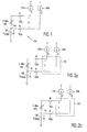
- a switch circuit e.g., switch circuit 201 of Figures 2(a) and 2(b) is provided which selectively connects each of current sources 104a and 104b to either terminal of 3-wire RTD 101.
- Switch circuit 201 may be implemented using four pass transistors.
- Figures 2(a) and 2(b) show, respectively, switch circuit 201 of temperature sensing circuit 200 connecting current sources 104a and 104b to terminals of 3-wire RTD 101 in one polarity configuration and in an opposite polarity configuration.
- 3-wire RTD 101 (resistance R RTD ) is connected in series with a sense resistor 106 (resistance R sense is known).
- Current sources 104a and 104b (providing currents I 1 and I 2 ) are connected respectively to first and second terminals of 3-wire RTD 101.
- the lead wires 102a and 102b that connect current sources 104a and 104b each have parasitic resistance R L .
- a first measurement of voltages V 1 and V 2 , across 3-wire RTD 101 and sensing resistor 106, respectively, is made in this first polarity configuration.
- V 2 2 * I 1 + I 2 * R sense
- R RTD 2 * R sense * V 1 / V 2
- the method of the present invention does not require currents I 1 and I 2 to be matched because, by making two measurements in opposite polarity configurations, the measured value of resistance R RTD is independent of the values of currents I 1 and I 2 .
Landscapes
- Physics & Mathematics (AREA)
- General Physics & Mathematics (AREA)
- Measuring Temperature Or Quantity Of Heat (AREA)
Abstract
Description
- The present invention relates to circuits and methods for detecting temperature. In particular, the present invention relates to circuits and methods for detecting temperature using accurate resistance measurements.
- The resistance temperature detector (RTD) is a common temperature sensor that varies its resistance with temperature.
Figure 1 showstemperature sensing circuit 100, which includes 3-wire RTD 101 that is conventionally used for temperature sensing. As shown inFigure 1 , 3-wire RTD 101 (resistance RRTD) is connected in series with sense resistor 106 (resistance Rsense).Current sources wire RTD 101. Thelead wires current sources wire RTD 101 each have parasitic resistance RL. Thus, voltage V1 across 3-wire RTD 101, including theparasitic lead resistors 
- The voltage across
sense resistor 106 is given by:
- The resistance RRTD can be obtained from these equations. These equations assume that resistance RL in each of
lead wires current sources current sources current sources lead wires 
- One drawback with the approach of
temperature sensing circuit 100 is added complexity in testing, manufacturing and design of matched current sources. - The present invention provides, in a temperature sensing circuit, a method for measuring a resistance of a RTD device to sense temperature. The method includes (a) connecting a first terminal of the RTD device to a first current source and connecting a second terminal of the RTD device to a second current source; (b) measuring a first voltage across the RTD device; (c) connecting the second terminal of the RTD device to the first current source and connecting the first terminal of the RTD device to the second current source; (d) measuring a second voltage across the RTD device; and (e) deriving the resistance of the RTD device based on the first voltage measurement and the second voltage measurement. The RTD device may be connected in series with a sense resistor to ground.
- To practice this method, according to one embodiment of the present invention, a temperature sensing circuit is provided, which includes (a) a first current source; (b) a second current source; and (c) a switch circuit configured, in a first configuration, to connect the first terminal of the RTD device to the first current source and the second terminal of the RTD device to the second current source, and configured, in a second configuration, to connect the second terminal of the RTD device to the first current source and the first terminal of the RTD device to the second current source. Each measurement of the resistance of the RTD device is made with two voltage measurements across the first and second terminals, in which the first voltage measurement has the switch circuit set in the first configuration and the second voltage measurement has the switch circuit set in the second configuration. The switch circuit may be implemented by pass transistors.
- The present invention is better understood upon consideration of the detailed description below in conjunction with the accompanying drawings.
-
-
Figure 1 showstemperature sensing circuit 100, which includes 3-wire RTD 101 that is conventionally used for temperature sensing. -
Figures 2(a) and 2(b) show, respectively,switch circuit 201 of temperature sensing circuit 200 connectingcurrent sources wire RTD 101 in one polarity configuration and in an opposite polarity configuration. - To facilitate comparison between figures, like elements may be provided like reference numerals across figures.
- The present invention provides a method for temperature sensing using a 3-wire resistance temperature detection (RTD) device without requiring the sensing circuit to have matched current sources. According to one embodiment of the present invention, a switch circuit (e.g.,
switch circuit 201 ofFigures 2(a) and 2(b) is provided which selectively connects each ofcurrent sources wire RTD 101.Switch circuit 201 may be implemented using four pass transistors.Figures 2(a) and 2(b) show, respectively,switch circuit 201 of temperature sensing circuit 200 connectingcurrent sources wire RTD 101 in one polarity configuration and in an opposite polarity configuration. As shown inFigure 2(a) , in the first polarity configuration, 3-wire RTD 101 (resistance RRTD) is connected in series with a sense resistor 106 (resistance Rsense is known).Current sources wire RTD 101. Thelead wires current sources wire RTD 101 and sensingresistor 106, respectively, is made in this first polarity configuration. As shown inFigure 2(b) , in the second polarity configuration,current sources wire RTD 101. A second measurement of voltages V1 and V2, across 3-wire RTD 101 and sensingresistor 106, respectively, is made in this second polarity configuration. - The sum total of the voltages of V1 across 3-
wire RTD 101, measured in the two measurements, is given by:
- The sum total of the voltages of V2 across
sense resistor 106, measured in the two measurements, is given by:
- Using these equations, the resistance of RRTD is given by:

- The method of the present invention does not require currents I1 and I2 to be matched because, by making two measurements in opposite polarity configurations, the measured value of resistance RRTD is independent of the values of currents I1 and I2.
- The detailed description above is provided to illustrate specific embodiments of the present invention and is not intended to be limiting. Numerous modifications and variations within the scope of the present invention are possible. The present invention is set forth in the accompanying claims.
Claims (6)
- A temperature sensing circuit for measuring the resistance of a RTD device having a first terminal and a second terminal, comprising:a first current source;a second current source; anda switch circuit configured, in a first configuration, to connect the first terminal of the RTD device to the first current source and the second terminal of the RTD device to the second current source, and configured, in a second configuration, to connect the second terminal of the RTD device to the first current source and the first terminal of the RTD device to the second current source.
- The temperature sensing circuit of Claim 1, wherein each measurement of the resistance of the RTD device is made with two voltage measurements across the first and second terminals, in which the first voltage measurement has the switch circuit set in the first configuration and the second voltage measurement has the switch circuit set in the second configuration.
- The temperature sensing circuit of Claim 1 or 2, wherein the RTD device is connected in series with a sense resistor to ground.
- The temperature sensing circuit of any one of Claims 1 - 3, wherein the switch circuit comprises pass transistors.
- A method for measuring the resistance of a RTD device having a first terminal and a second terminal, comprising:connecting the first terminal of the RTD device to a first current source and connecting the second terminal of the RTD device to a second current source;measuring a first voltage across the RTD device;connecting the second terminal of the RTD device to the first current source and connecting the first terminal of the RTD device to the second current source;measuring a second voltage across the RTD device; andderiving the resistance of the RTD device based on the first voltage measurement and the second voltage measurement.
- The method of Claim 5, wherein RTD device is connected in series with a sense resistor to ground.
Priority Applications (1)
| Application Number | Priority Date | Filing Date | Title |
|---|---|---|---|
| EP14001073.7A EP2921832B1 (en) | 2014-03-21 | 2014-03-21 | 3-wire resistance temperature detector and method of measuring said resistance |
Applications Claiming Priority (1)
| Application Number | Priority Date | Filing Date | Title |
|---|---|---|---|
| EP14001073.7A EP2921832B1 (en) | 2014-03-21 | 2014-03-21 | 3-wire resistance temperature detector and method of measuring said resistance |
Publications (2)
| Publication Number | Publication Date |
|---|---|
| EP2921832A1 true EP2921832A1 (en) | 2015-09-23 |
| EP2921832B1 EP2921832B1 (en) | 2016-06-15 |
Family
ID=50389761
Family Applications (1)
| Application Number | Title | Priority Date | Filing Date |
|---|---|---|---|
| EP14001073.7A Active EP2921832B1 (en) | 2014-03-21 | 2014-03-21 | 3-wire resistance temperature detector and method of measuring said resistance |
Country Status (1)
| Country | Link |
|---|---|
| EP (1) | EP2921832B1 (en) |
Citations (3)
| Publication number | Priority date | Publication date | Assignee | Title |
|---|---|---|---|---|
| US3913403A (en) * | 1973-10-11 | 1975-10-21 | Leeds & Northrup Co | Temperature measurement with three-lead resistance thermometers by dual constant current method |
| US4102199A (en) * | 1976-08-26 | 1978-07-25 | Megasystems, Inc. | RTD measurement system |
| US5351010A (en) * | 1991-08-16 | 1994-09-27 | Hans Leopold | Resistance ratio measurement utilizing measuring currents of opposite plural direction |
-
2014
- 2014-03-21 EP EP14001073.7A patent/EP2921832B1/en active Active
Patent Citations (3)
| Publication number | Priority date | Publication date | Assignee | Title |
|---|---|---|---|---|
| US3913403A (en) * | 1973-10-11 | 1975-10-21 | Leeds & Northrup Co | Temperature measurement with three-lead resistance thermometers by dual constant current method |
| US4102199A (en) * | 1976-08-26 | 1978-07-25 | Megasystems, Inc. | RTD measurement system |
| US5351010A (en) * | 1991-08-16 | 1994-09-27 | Hans Leopold | Resistance ratio measurement utilizing measuring currents of opposite plural direction |
Also Published As
| Publication number | Publication date |
|---|---|
| EP2921832B1 (en) | 2016-06-15 |
Similar Documents
| Publication | Publication Date | Title |
|---|---|---|
| EP2988136B1 (en) | Sensor interface circuits | |
| EP3022737B1 (en) | Current sense circuit with offset calibration | |
| US9714962B2 (en) | Monitoring device and method for monitoring a line section using a monitoring device | |
| US10359321B2 (en) | On-chip circuit and method for accurately measuring die temperature of an integrated circuit | |
| CN105004927A (en) | Bridge resistor and its application | |
| EP0496147A1 (en) | Method of precise measurement of small resistance values | |
| US20180106837A1 (en) | Electronics tester with output circuits operable in voltage compensated power mode, driver mode or current compensated power mode | |
| EP2833157A1 (en) | Identifying defective electrical cables | |
| CN105277112A (en) | A half-bridge Wheatstone bridge strain measuring system and method capable of eliminating conductor resistance influence | |
| Lee et al. | From AC quantum voltmeter to quantum calibrator | |
| US9482714B2 (en) | Systems and methods for overheat detection system event location | |
| EP2921832B1 (en) | 3-wire resistance temperature detector and method of measuring said resistance | |
| US20140241400A1 (en) | Rotating 3-wire resistance temperature detection excitation current sources and method | |
| CN106066200A (en) | Electromagnetic flowmeter scale detector | |
| Rietveld et al. | Accurate high-ohmic resistance measurement techniques up to 1 PΩ | |
| US20170097386A1 (en) | Apparatus and methods for measuring electrical current | |
| US9797958B2 (en) | Monitoring system | |
| US10024728B2 (en) | Circuit and arrangement for 3-wire measurements with input protection | |
| CN100570379C (en) | Method and converter for online measurement of resistance value of one resistance in loop resistance by digital multimeter | |
| Rietveld et al. | Accurate high-ohmic resistance measurement techniques up to 1 PΩ | |
| RU178894U1 (en) | SMALL RESISTANCE METER | |
| Rietveld et al. | Active-arm resistance bridge with voltage null-detection for precision measurement of resistances above 1 MΩ | |
| UA116906C2 (en) | METHOD OF OUTSIDE MEASUREMENTS OF RESISTOR AND RESISTANCE SENSOR RESISTANCE AND DIGITAL MEASURER THAT REALIZES IT | |
| RU2405131C1 (en) | Temperature difference metre with thermistor transducers | |
| Kučera et al. | Realization of the ultrahigh-ohmic resistance scale at CMI |
Legal Events
| Date | Code | Title | Description |
|---|---|---|---|
| PUAI | Public reference made under article 153(3) epc to a published international application that has entered the european phase |
Free format text: ORIGINAL CODE: 0009012 |
|
| AK | Designated contracting states |
Kind code of ref document: A1 Designated state(s): AL AT BE BG CH CY CZ DE DK EE ES FI FR GB GR HR HU IE IS IT LI LT LU LV MC MK MT NL NO PL PT RO RS SE SI SK SM TR |
|
| AX | Request for extension of the european patent |
Extension state: BA ME |
|
| 17P | Request for examination filed |
Effective date: 20151029 |
|
| RBV | Designated contracting states (corrected) |
Designated state(s): AL AT BE BG CH CY CZ DE DK EE ES FI FR GB GR HR HU IE IS IT LI LT LU LV MC MK MT NL NO PL PT RO RS SE SI SK SM TR |
|
| GRAP | Despatch of communication of intention to grant a patent |
Free format text: ORIGINAL CODE: EPIDOSNIGR1 |
|
| INTG | Intention to grant announced |
Effective date: 20160121 |
|
| GRAS | Grant fee paid |
Free format text: ORIGINAL CODE: EPIDOSNIGR3 |
|
| GRAA | (expected) grant |
Free format text: ORIGINAL CODE: 0009210 |
|
| AK | Designated contracting states |
Kind code of ref document: B1 Designated state(s): AL AT BE BG CH CY CZ DE DK EE ES FI FR GB GR HR HU IE IS IT LI LT LU LV MC MK MT NL NO PL PT RO RS SE SI SK SM TR |
|
| REG | Reference to a national code |
Ref country code: CH Ref legal event code: EP Ref country code: GB Ref legal event code: FG4D |
|
| REG | Reference to a national code |
Ref country code: IE Ref legal event code: FG4D |
|
| REG | Reference to a national code |
Ref country code: AT Ref legal event code: REF Ref document number: 806740 Country of ref document: AT Kind code of ref document: T Effective date: 20160715 |
|
| REG | Reference to a national code |
Ref country code: DE Ref legal event code: R096 Ref document number: 602014002273 Country of ref document: DE |
|
| REG | Reference to a national code |
Ref country code: NL Ref legal event code: FP |
|
| REG | Reference to a national code |
Ref country code: LT Ref legal event code: MG4D |
|
| PG25 | Lapsed in a contracting state [announced via postgrant information from national office to epo] |
Ref country code: NO Free format text: LAPSE BECAUSE OF FAILURE TO SUBMIT A TRANSLATION OF THE DESCRIPTION OR TO PAY THE FEE WITHIN THE PRESCRIBED TIME-LIMIT Effective date: 20160915 Ref country code: LT Free format text: LAPSE BECAUSE OF FAILURE TO SUBMIT A TRANSLATION OF THE DESCRIPTION OR TO PAY THE FEE WITHIN THE PRESCRIBED TIME-LIMIT Effective date: 20160615 Ref country code: FI Free format text: LAPSE BECAUSE OF FAILURE TO SUBMIT A TRANSLATION OF THE DESCRIPTION OR TO PAY THE FEE WITHIN THE PRESCRIBED TIME-LIMIT Effective date: 20160615 |
|
| REG | Reference to a national code |
Ref country code: AT Ref legal event code: MK05 Ref document number: 806740 Country of ref document: AT Kind code of ref document: T Effective date: 20160615 |
|
| PG25 | Lapsed in a contracting state [announced via postgrant information from national office to epo] |
Ref country code: GR Free format text: LAPSE BECAUSE OF FAILURE TO SUBMIT A TRANSLATION OF THE DESCRIPTION OR TO PAY THE FEE WITHIN THE PRESCRIBED TIME-LIMIT Effective date: 20160916 Ref country code: HR Free format text: LAPSE BECAUSE OF FAILURE TO SUBMIT A TRANSLATION OF THE DESCRIPTION OR TO PAY THE FEE WITHIN THE PRESCRIBED TIME-LIMIT Effective date: 20160615 Ref country code: LV Free format text: LAPSE BECAUSE OF FAILURE TO SUBMIT A TRANSLATION OF THE DESCRIPTION OR TO PAY THE FEE WITHIN THE PRESCRIBED TIME-LIMIT Effective date: 20160615 Ref country code: SE Free format text: LAPSE BECAUSE OF FAILURE TO SUBMIT A TRANSLATION OF THE DESCRIPTION OR TO PAY THE FEE WITHIN THE PRESCRIBED TIME-LIMIT Effective date: 20160615 Ref country code: RS Free format text: LAPSE BECAUSE OF FAILURE TO SUBMIT A TRANSLATION OF THE DESCRIPTION OR TO PAY THE FEE WITHIN THE PRESCRIBED TIME-LIMIT Effective date: 20160615 |
|
| PG25 | Lapsed in a contracting state [announced via postgrant information from national office to epo] |
Ref country code: RO Free format text: LAPSE BECAUSE OF FAILURE TO SUBMIT A TRANSLATION OF THE DESCRIPTION OR TO PAY THE FEE WITHIN THE PRESCRIBED TIME-LIMIT Effective date: 20160615 Ref country code: CZ Free format text: LAPSE BECAUSE OF FAILURE TO SUBMIT A TRANSLATION OF THE DESCRIPTION OR TO PAY THE FEE WITHIN THE PRESCRIBED TIME-LIMIT Effective date: 20160615 Ref country code: IS Free format text: LAPSE BECAUSE OF FAILURE TO SUBMIT A TRANSLATION OF THE DESCRIPTION OR TO PAY THE FEE WITHIN THE PRESCRIBED TIME-LIMIT Effective date: 20161015 Ref country code: SK Free format text: LAPSE BECAUSE OF FAILURE TO SUBMIT A TRANSLATION OF THE DESCRIPTION OR TO PAY THE FEE WITHIN THE PRESCRIBED TIME-LIMIT Effective date: 20160615 Ref country code: EE Free format text: LAPSE BECAUSE OF FAILURE TO SUBMIT A TRANSLATION OF THE DESCRIPTION OR TO PAY THE FEE WITHIN THE PRESCRIBED TIME-LIMIT Effective date: 20160615 |
|
| PG25 | Lapsed in a contracting state [announced via postgrant information from national office to epo] |
Ref country code: SM Free format text: LAPSE BECAUSE OF FAILURE TO SUBMIT A TRANSLATION OF THE DESCRIPTION OR TO PAY THE FEE WITHIN THE PRESCRIBED TIME-LIMIT Effective date: 20160615 Ref country code: AT Free format text: LAPSE BECAUSE OF FAILURE TO SUBMIT A TRANSLATION OF THE DESCRIPTION OR TO PAY THE FEE WITHIN THE PRESCRIBED TIME-LIMIT Effective date: 20160615 Ref country code: PT Free format text: LAPSE BECAUSE OF FAILURE TO SUBMIT A TRANSLATION OF THE DESCRIPTION OR TO PAY THE FEE WITHIN THE PRESCRIBED TIME-LIMIT Effective date: 20161017 Ref country code: PL Free format text: LAPSE BECAUSE OF FAILURE TO SUBMIT A TRANSLATION OF THE DESCRIPTION OR TO PAY THE FEE WITHIN THE PRESCRIBED TIME-LIMIT Effective date: 20160615 Ref country code: BE Free format text: LAPSE BECAUSE OF FAILURE TO SUBMIT A TRANSLATION OF THE DESCRIPTION OR TO PAY THE FEE WITHIN THE PRESCRIBED TIME-LIMIT Effective date: 20160615 Ref country code: ES Free format text: LAPSE BECAUSE OF FAILURE TO SUBMIT A TRANSLATION OF THE DESCRIPTION OR TO PAY THE FEE WITHIN THE PRESCRIBED TIME-LIMIT Effective date: 20160615 |
|
| REG | Reference to a national code |
Ref country code: DE Ref legal event code: R097 Ref document number: 602014002273 Country of ref document: DE |
|
| REG | Reference to a national code |
Ref country code: FR Ref legal event code: PLFP Year of fee payment: 4 |
|
| PLBE | No opposition filed within time limit |
Free format text: ORIGINAL CODE: 0009261 |
|
| STAA | Information on the status of an ep patent application or granted ep patent |
Free format text: STATUS: NO OPPOSITION FILED WITHIN TIME LIMIT |
|
| 26N | No opposition filed |
Effective date: 20170316 |
|
| PG25 | Lapsed in a contracting state [announced via postgrant information from national office to epo] |
Ref country code: DK Free format text: LAPSE BECAUSE OF FAILURE TO SUBMIT A TRANSLATION OF THE DESCRIPTION OR TO PAY THE FEE WITHIN THE PRESCRIBED TIME-LIMIT Effective date: 20160615 |
|
| PG25 | Lapsed in a contracting state [announced via postgrant information from national office to epo] |
Ref country code: SI Free format text: LAPSE BECAUSE OF FAILURE TO SUBMIT A TRANSLATION OF THE DESCRIPTION OR TO PAY THE FEE WITHIN THE PRESCRIBED TIME-LIMIT Effective date: 20160615 |
|
| REG | Reference to a national code |
Ref country code: CH Ref legal event code: PL |
|
| PG25 | Lapsed in a contracting state [announced via postgrant information from national office to epo] |
Ref country code: MC Free format text: LAPSE BECAUSE OF FAILURE TO SUBMIT A TRANSLATION OF THE DESCRIPTION OR TO PAY THE FEE WITHIN THE PRESCRIBED TIME-LIMIT Effective date: 20160615 |
|
| PG25 | Lapsed in a contracting state [announced via postgrant information from national office to epo] |
Ref country code: LU Free format text: LAPSE BECAUSE OF NON-PAYMENT OF DUE FEES Effective date: 20170321 |
|
| REG | Reference to a national code |
Ref country code: FR Ref legal event code: PLFP Year of fee payment: 5 |
|
| PG25 | Lapsed in a contracting state [announced via postgrant information from national office to epo] |
Ref country code: IE Free format text: LAPSE BECAUSE OF NON-PAYMENT OF DUE FEES Effective date: 20170321 Ref country code: LI Free format text: LAPSE BECAUSE OF NON-PAYMENT OF DUE FEES Effective date: 20170331 Ref country code: CH Free format text: LAPSE BECAUSE OF NON-PAYMENT OF DUE FEES Effective date: 20170331 |
|
| PG25 | Lapsed in a contracting state [announced via postgrant information from national office to epo] |
Ref country code: MT Free format text: LAPSE BECAUSE OF NON-PAYMENT OF DUE FEES Effective date: 20170321 |
|
| PG25 | Lapsed in a contracting state [announced via postgrant information from national office to epo] |
Ref country code: AL Free format text: LAPSE BECAUSE OF FAILURE TO SUBMIT A TRANSLATION OF THE DESCRIPTION OR TO PAY THE FEE WITHIN THE PRESCRIBED TIME-LIMIT Effective date: 20160615 |
|
| PG25 | Lapsed in a contracting state [announced via postgrant information from national office to epo] |
Ref country code: HU Free format text: LAPSE BECAUSE OF FAILURE TO SUBMIT A TRANSLATION OF THE DESCRIPTION OR TO PAY THE FEE WITHIN THE PRESCRIBED TIME-LIMIT; INVALID AB INITIO Effective date: 20140321 |
|
| PG25 | Lapsed in a contracting state [announced via postgrant information from national office to epo] |
Ref country code: BG Free format text: LAPSE BECAUSE OF FAILURE TO SUBMIT A TRANSLATION OF THE DESCRIPTION OR TO PAY THE FEE WITHIN THE PRESCRIBED TIME-LIMIT Effective date: 20160615 |
|
| PG25 | Lapsed in a contracting state [announced via postgrant information from national office to epo] |
Ref country code: CY Free format text: LAPSE BECAUSE OF FAILURE TO SUBMIT A TRANSLATION OF THE DESCRIPTION OR TO PAY THE FEE WITHIN THE PRESCRIBED TIME-LIMIT Effective date: 20160615 |
|
| PG25 | Lapsed in a contracting state [announced via postgrant information from national office to epo] |
Ref country code: MK Free format text: LAPSE BECAUSE OF FAILURE TO SUBMIT A TRANSLATION OF THE DESCRIPTION OR TO PAY THE FEE WITHIN THE PRESCRIBED TIME-LIMIT Effective date: 20160615 |
|
| PG25 | Lapsed in a contracting state [announced via postgrant information from national office to epo] |
Ref country code: TR Free format text: LAPSE BECAUSE OF FAILURE TO SUBMIT A TRANSLATION OF THE DESCRIPTION OR TO PAY THE FEE WITHIN THE PRESCRIBED TIME-LIMIT Effective date: 20160615 |
|
| REG | Reference to a national code |
Ref country code: DE Ref legal event code: R082 Ref document number: 602014002273 Country of ref document: DE Representative=s name: MUELLER-BORE & PARTNER PATENTANWAELTE PARTG MB, DE Ref country code: DE Ref legal event code: R081 Ref document number: 602014002273 Country of ref document: DE Owner name: ANALOG DEVICES INTERNATIONAL UNLIMITED COMPANY, IE Free format text: FORMER OWNER: LINEAR TECHNOLOGY CORPORATION, MILPITAS, CALIF., US Ref country code: DE Ref legal event code: R082 Ref document number: 602014002273 Country of ref document: DE Representative=s name: WITHERS & ROGERS LLP, DE |
|
| REG | Reference to a national code |
Ref country code: DE Ref legal event code: R082 Ref document number: 602014002273 Country of ref document: DE Representative=s name: WITHERS & ROGERS LLP, DE |
|
| REG | Reference to a national code |
Ref country code: GB Ref legal event code: 732E Free format text: REGISTERED BETWEEN 20211125 AND 20211201 |
|
| REG | Reference to a national code |
Ref country code: NL Ref legal event code: PD Owner name: ANALOG DEVICES INTERNATIONAL UNLIMITED COMPANY; IE Free format text: DETAILS ASSIGNMENT: CHANGE OF OWNER(S), ASSIGNMENT; FORMER OWNER NAME: LINEAR TECHNOLOGY LLC Effective date: 20211216 |
|
| PGFP | Annual fee paid to national office [announced via postgrant information from national office to epo] |
Ref country code: IT Payment date: 20220217 Year of fee payment: 9 |
|
| PG25 | Lapsed in a contracting state [announced via postgrant information from national office to epo] |
Ref country code: IT Free format text: LAPSE BECAUSE OF NON-PAYMENT OF DUE FEES Effective date: 20230321 |
|
| PGFP | Annual fee paid to national office [announced via postgrant information from national office to epo] |
Ref country code: NL Payment date: 20260219 Year of fee payment: 13 |
|
| PGFP | Annual fee paid to national office [announced via postgrant information from national office to epo] |
Ref country code: GB Payment date: 20260220 Year of fee payment: 13 |
|
| PGFP | Annual fee paid to national office [announced via postgrant information from national office to epo] |
Ref country code: DE Payment date: 20260219 Year of fee payment: 13 |
|
| PGFP | Annual fee paid to national office [announced via postgrant information from national office to epo] |
Ref country code: FR Payment date: 20260219 Year of fee payment: 13 |