EP2921789A1 - Hot-water supply system and method of controlling the same - Google Patents
Hot-water supply system and method of controlling the same Download PDFInfo
- Publication number
- EP2921789A1 EP2921789A1 EP15158680.7A EP15158680A EP2921789A1 EP 2921789 A1 EP2921789 A1 EP 2921789A1 EP 15158680 A EP15158680 A EP 15158680A EP 2921789 A1 EP2921789 A1 EP 2921789A1
- Authority
- EP
- European Patent Office
- Prior art keywords
- hot
- water
- heat source
- source device
- stored
- Prior art date
- Legal status (The legal status is an assumption and is not a legal conclusion. Google has not performed a legal analysis and makes no representation as to the accuracy of the status listed.)
- Granted
Links
Images

Classifications
-
- F—MECHANICAL ENGINEERING; LIGHTING; HEATING; WEAPONS; BLASTING
- F24—HEATING; RANGES; VENTILATING
- F24D—DOMESTIC- OR SPACE-HEATING SYSTEMS, e.g. CENTRAL HEATING SYSTEMS; DOMESTIC HOT-WATER SUPPLY SYSTEMS; ELEMENTS OR COMPONENTS THEREFOR
- F24D19/00—Details
- F24D19/10—Arrangement or mounting of control or safety devices
- F24D19/1006—Arrangement or mounting of control or safety devices for water heating systems
- F24D19/1009—Arrangement or mounting of control or safety devices for water heating systems for central heating
- F24D19/1039—Arrangement or mounting of control or safety devices for water heating systems for central heating the system uses a heat pump
-
- F—MECHANICAL ENGINEERING; LIGHTING; HEATING; WEAPONS; BLASTING
- F24—HEATING; RANGES; VENTILATING
- F24D—DOMESTIC- OR SPACE-HEATING SYSTEMS, e.g. CENTRAL HEATING SYSTEMS; DOMESTIC HOT-WATER SUPPLY SYSTEMS; ELEMENTS OR COMPONENTS THEREFOR
- F24D11/00—Central heating systems using heat accumulated in storage masses
- F24D11/02—Central heating systems using heat accumulated in storage masses using heat pumps
-
- F—MECHANICAL ENGINEERING; LIGHTING; HEATING; WEAPONS; BLASTING
- F24—HEATING; RANGES; VENTILATING
- F24D—DOMESTIC- OR SPACE-HEATING SYSTEMS, e.g. CENTRAL HEATING SYSTEMS; DOMESTIC HOT-WATER SUPPLY SYSTEMS; ELEMENTS OR COMPONENTS THEREFOR
- F24D17/00—Domestic hot-water supply systems
- F24D17/02—Domestic hot-water supply systems using heat pumps
-
- F—MECHANICAL ENGINEERING; LIGHTING; HEATING; WEAPONS; BLASTING
- F24—HEATING; RANGES; VENTILATING
- F24D—DOMESTIC- OR SPACE-HEATING SYSTEMS, e.g. CENTRAL HEATING SYSTEMS; DOMESTIC HOT-WATER SUPPLY SYSTEMS; ELEMENTS OR COMPONENTS THEREFOR
- F24D19/00—Details
- F24D19/10—Arrangement or mounting of control or safety devices
- F24D19/1006—Arrangement or mounting of control or safety devices for water heating systems
- F24D19/1051—Arrangement or mounting of control or safety devices for water heating systems for domestic hot water
- F24D19/1054—Arrangement or mounting of control or safety devices for water heating systems for domestic hot water the system uses a heat pump
-
- F—MECHANICAL ENGINEERING; LIGHTING; HEATING; WEAPONS; BLASTING
- F24—HEATING; RANGES; VENTILATING
- F24D—DOMESTIC- OR SPACE-HEATING SYSTEMS, e.g. CENTRAL HEATING SYSTEMS; DOMESTIC HOT-WATER SUPPLY SYSTEMS; ELEMENTS OR COMPONENTS THEREFOR
- F24D19/00—Details
- F24D19/10—Arrangement or mounting of control or safety devices
- F24D19/1006—Arrangement or mounting of control or safety devices for water heating systems
- F24D19/1066—Arrangement or mounting of control or safety devices for water heating systems for the combination of central heating and domestic hot water
- F24D19/1072—Arrangement or mounting of control or safety devices for water heating systems for the combination of central heating and domestic hot water the system uses a heat pump
-
- F—MECHANICAL ENGINEERING; LIGHTING; HEATING; WEAPONS; BLASTING
- F24—HEATING; RANGES; VENTILATING
- F24H—FLUID HEATERS, e.g. WATER OR AIR HEATERS, HAVING HEAT-GENERATING MEANS, e.g. HEAT PUMPS, IN GENERAL
- F24H15/00—Control of fluid heaters
- F24H15/20—Control of fluid heaters characterised by control inputs
-
- F—MECHANICAL ENGINEERING; LIGHTING; HEATING; WEAPONS; BLASTING
- F24—HEATING; RANGES; VENTILATING
- F24H—FLUID HEATERS, e.g. WATER OR AIR HEATERS, HAVING HEAT-GENERATING MEANS, e.g. HEAT PUMPS, IN GENERAL
- F24H15/00—Control of fluid heaters
- F24H15/20—Control of fluid heaters characterised by control inputs
- F24H15/212—Temperature of the water
- F24H15/215—Temperature of the water before heating
-
- F—MECHANICAL ENGINEERING; LIGHTING; HEATING; WEAPONS; BLASTING
- F24—HEATING; RANGES; VENTILATING
- F24H—FLUID HEATERS, e.g. WATER OR AIR HEATERS, HAVING HEAT-GENERATING MEANS, e.g. HEAT PUMPS, IN GENERAL
- F24H15/00—Control of fluid heaters
- F24H15/20—Control of fluid heaters characterised by control inputs
- F24H15/212—Temperature of the water
- F24H15/219—Temperature of the water after heating
-
- F—MECHANICAL ENGINEERING; LIGHTING; HEATING; WEAPONS; BLASTING
- F24—HEATING; RANGES; VENTILATING
- F24H—FLUID HEATERS, e.g. WATER OR AIR HEATERS, HAVING HEAT-GENERATING MEANS, e.g. HEAT PUMPS, IN GENERAL
- F24H15/00—Control of fluid heaters
- F24H15/30—Control of fluid heaters characterised by control outputs; characterised by the components to be controlled
- F24H15/355—Control of heat-generating means in heaters
-
- F—MECHANICAL ENGINEERING; LIGHTING; HEATING; WEAPONS; BLASTING
- F24—HEATING; RANGES; VENTILATING
- F24D—DOMESTIC- OR SPACE-HEATING SYSTEMS, e.g. CENTRAL HEATING SYSTEMS; DOMESTIC HOT-WATER SUPPLY SYSTEMS; ELEMENTS OR COMPONENTS THEREFOR
- F24D2240/00—Characterizing positions, e.g. of sensors, inlets, outlets
- F24D2240/26—Vertically distributed at fixed positions, e.g. multiple sensors distributed over the height of a tank, or a vertical inlet distribution pipe having a plurality of orifices
-
- F—MECHANICAL ENGINEERING; LIGHTING; HEATING; WEAPONS; BLASTING
- F24—HEATING; RANGES; VENTILATING
- F24H—FLUID HEATERS, e.g. WATER OR AIR HEATERS, HAVING HEAT-GENERATING MEANS, e.g. HEAT PUMPS, IN GENERAL
- F24H15/00—Control of fluid heaters
- F24H15/20—Control of fluid heaters characterised by control inputs
- F24H15/212—Temperature of the water
- F24H15/223—Temperature of the water in the water storage tank
-
- F—MECHANICAL ENGINEERING; LIGHTING; HEATING; WEAPONS; BLASTING
- F24—HEATING; RANGES; VENTILATING
- F24H—FLUID HEATERS, e.g. WATER OR AIR HEATERS, HAVING HEAT-GENERATING MEANS, e.g. HEAT PUMPS, IN GENERAL
- F24H15/00—Control of fluid heaters
- F24H15/30—Control of fluid heaters characterised by control outputs; characterised by the components to be controlled
- F24H15/375—Control of heat pumps
- F24H15/38—Control of compressors of heat pumps
-
- F—MECHANICAL ENGINEERING; LIGHTING; HEATING; WEAPONS; BLASTING
- F24—HEATING; RANGES; VENTILATING
- F24H—FLUID HEATERS, e.g. WATER OR AIR HEATERS, HAVING HEAT-GENERATING MEANS, e.g. HEAT PUMPS, IN GENERAL
- F24H15/00—Control of fluid heaters
- F24H15/40—Control of fluid heaters characterised by the type of controllers
- F24H15/414—Control of fluid heaters characterised by the type of controllers using electronic processing, e.g. computer-based
Definitions
- the present invention relates to a hot-water supply system and a method of controlling the same.
- a domestic heat-pump hot-water supply apparatus includes a heat source device (heat pump unit) constituting a refrigerant circuit through which refrigerant circulates so that heat is exchanged between outdoor air and the refrigerant, and a hot-water storage tank that stores hot water heated by the heat source device.
- a hot-water-supply control unit provided in a tank unit containing the hot-water storage tank receives outputs from individual sensors in the tank unit and controls the operation of individual devices, which enables hot-water supply and bath operation according to settings made from a remote controller connected to the hot-water-supply control unit.
- an extended electrical wire connected to a temperature sensor or a water-level sensor installed in a hot-water storage tank is provided between a heat source device and the hot-water storage tank, and is connected to a control unit provided on the side of the heat source device, and the control unit on the side of the heat source device controls the heat source device based on information obtained from various sensors via electrical wires.
- the present invention has been made in view of the situation described above, and it is an object thereof to provide a hot-water supply system and a method of controlling the same with which it is possible to convey information obtained from the side of a hot-water storage tank correctly to the side of a heat source device.
- the present invention employs the following solutions.
- a first aspect of the present invention is a hot-water supply system including a heat source device; a hot-water-stored-amount detecting means that detects the amount of hot water stored in a hot-water storage tank that stores hot water heated by the heat source device; an electrical valve that is provided in a path of supplying the hot water heated by the heat source device to the hot-water storage tank and that adjusts the flow level of hot water supplied to the hot-water storage tank according to a control signal; a controlling means that is provided in the heat source device and that controls the heat source device based on information about the amount of stored hot water detected by the hot-water-stored-amount detecting means and based on a degree-of-opening signal of the electrical valve; and an interface means that is connected to the hot-water-stored-amount detecting means and the electrical valve via electrical wires so that the information about the amount of stored hot water detected by the hot-water-stored-amount detecting means and the degree-of-opening signal of the electrical valve can be input and output
- the information is sent to the interface means via the electrical wires, and the degree-of-opening signal of the electrical valve on the path for supplying the hot water heated by the heat source device to the hot-water storage tank is sent to the interface means via the electrical wires.
- the information about the amount of stored hot water and the degree-of-opening signal of the electrical valve, obtained via the electrical wires, are converted into signals that can be sent and received via the communication line and sent to the controlling means via the communication line interconnecting the interface means and the controlling means.
- the controlling means controls the heat source device based on the information about the amount of stored hot water and the degree-of-opening signal of the electrical valve, obtained via the communication line.
- the interface means is provided between the heat source device and the hot-water storage tank, the interface means and the heat source device are connected to each other via the communication line, and information about the amount of stored hot water and information about the degree-of-opening signal of the electrical valve are input to the heat source device via the communication line.
- the information about the amount of stored hot water and the information about the degree-of-opening signal of the electrical valve are delivered to the heat source device more reliably compared with before.
- the case where the heat source device and the hot-water storage tank are remote from each other refers to the case where, for example, the distance therebetween is 20 m or longer.
- the controlling means may include a second connecting means that makes it possible to send information to and receive information from the hot-water-stored-amount detecting means via the electrical wires and a third connecting means that makes it possible to send information to and receive information from the electrical valve via the electrical wires.
- the communication line or the electrical wires are to be used for input and output of information to and from the controlling means provided in the heat source device.
- the above hot-water supply system may further include a temperature detecting means that is installed in the vicinity of an inlet for hot water that flows into the hot-water storage tank, that detects the temperature at the inlet of the hot-water storage tank, and that outputs information about the detected temperature to the controlling means, and the controlling means may control the heat source device based on the temperature detected by the temperature detecting means.
- the heat source device and the hot-water storage tank are remote from each other, it is conceivable that hot water heated by the heat source device dissipates heat in the middle of the path and that its temperature becomes lower than the temperature reached by being heated by the heat source device at the time when the hot water is supplied to the hot-water storage tank.
- the heat source device is controlled in accordance with the temperature at the inlet of the hot-water storage tank, it is possible to supply hot water at a desired temperature to the hot-water storage tank in consideration of heat dissipation even in the case where the heat source device and the hot-water storage tank are remote from each other.
- a second aspect of the present invention is a method of controlling a hot-water supply system, including a first step of detecting the amount of hot water stored in a hot-water storage tank that stores hot water heated by a heat source device; a second step of adjusting the flow level of hot water supplied to the hot-water storage tank according to a control signal for an electrical valve that is provided in a path of supplying hot water heated by the heat source device to the hot-water storage tank; a third step of controlling the heat source device at the side of the heat source device based on information about the amount of stored hot water detected and a degree-of-opening signal of the electrical valve; and a fourth step of inputting and outputting the information about the amount of stored hot water detected in the first step and the degree-of-opening signal of the electrical valve via electrical wires and converting the information about the amount of stored hot water and the degree-of-opening signal of the electrical valve input and output via the electrical wires into signals that can be sent and received via a communication line.
- an advantage is afforded in that it is possible to convey information that is obtained from the side of a hot-water storage tank correctly to the side of a heat source device.
- a hot-water supply system is a commercial/industrial-use EcoCute (registered trademark) system that can supply an amount of hot water adequate for a large-scale facility by using a heat source device (heat pump unit) utilizing natural CO 2 refrigerant in combination with a hot-water storage unit.
- a heat source device heat pump unit
- CO 2 refrigerant natural CO 2 refrigerant
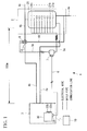
- the hot-water supply unit 1 includes a heat source device 3, a hot-water storage unit 2, water pipes 4a, 4b, 4c, 4d, and 4e, electrical wires 5a and 5b, a communication line 6, an interface unit (interface means) 7, and a temperature detecting unit (temperature detecting means) 8.
- the CO 2 refrigerant absorbs heat in the air, the refrigerant is compressed by a compressor to raise its temperature, and heat is transferred from the high-temperature refrigerant to boil water to a specified temperature.
- the heat source device 3 in this embodiment is a supercritical-cycle heat pump filled with CO 2 refrigerant as a working medium, and this heat pump itself may be a known heat pump.
- a supercritical-cycle heat pump utilizing CO 2 refrigerant is described here as an example of the heat source device 3
- the heat source device 3 need not necessarily be implemented by a heat pump in this embodiment and may instead be implemented by other equipment, such as a boiler or a fuel cell.
- the heat source device 3 is connected to the water pipe 4a for introducing water that is supplied from the side of the hot-water storage unit 2 and to the water pipe 4b for discharging high-temperature water.
- the heat source device 3 heats low-temperature water supplied from the water pipe 4a and supplies the heated high-temperature water (e.g., about 60 to 70 °C, hereinafter also referred to as "hot water") to the water pipe 4b.
- heated high-temperature water e.g., about 60 to 70 °C, hereinafter also referred to as "hot water
- the water pipe 4c is a hot-water supply path for supplying hot water stored in a hot-water storage tank 20 to a supply destination.
- the water pipe 4d is a path through which the hot water discharged from the heat source device 3 is introduced to the bottom side of the hot-water storage tank 20 in the case where the temperature of the discharged hot water is below a desired temperature (specified temperature), whereby the hot water is bypassed to the water pipe 4e.
- the water pipe 4e is a pipe for supplying low-temperature water to the hot-water storage tank 20 and is connected to a water supply.
- the hot-water storage unit 2 includes the hot-water storage tank 20 and hot-water-stored-amount detecting units (hot-water-stored-amount detecting means) 21a, 21b ..., and 21n. Unless explicitly specified, these hot-water-stored-amount detecting units will be simply referred to as hot-water-stored-amount detecting units 21.
- the hot-water storage tank 20 receives water (e.g., 10 °C) from the water supply via the water pipe 4e and also receives hot water (e.g., about 60 to 70 °C) heated by the heat source device 3 from the top side via the water pipe 4b. Thus, temperature layers constituted of water on the lower side and the hot water on the upper side are formed in the hot-water storage tank 20.
- the hot-water-stored-amount detecting units 21 are provided in the hot-water storage tank 20 and detect the boundary between the temperature layers.
- the multiple hot-water-stored-amount detecting units 21 are provided in the hot-water storage tank 20 and detect the amount of hot water stored in the hot-water storage tank 20, which stores hot water heated by the heat source device 3.
- thermistors that serve as temperature sensors are provided along the vertical direction (top-bottom direction) to constitute the hot-water-stored-amount detecting units 21a, 21b, ..., and 21n.
- the hot-water-stored-amount detecting unit 21a is a temperature sensor installed at a position corresponding to 100% of the hot-water storage capacity.
- the hot-water-stored-amount detecting unit 21b is a temperature sensor installed at a position corresponding to 90% of the hot-water storage capacity
- the hot-water-stored-amount detecting unit 21n is a temperature sensor installed at a position corresponding to 10% of the hot-water storage capacity.
- Information about the temperatures detected by the individual hot-water-stored-amount detecting units (temperature sensors) 21a, 21b, ..., and 21n is output to the interface unit 7. Furthermore, when the information about the temperatures detected by the individual temperature sensors is output to the control unit 30 (described later in detail), the control unit 30 is able to detect the boundary of the temperature and detect the amount of stored hot water based on the position of the temperature sensor that has detected the temperature at the boundary.
- the thermistors have characteristics such that their resistances decrease as the temperatures become higher and their resistances increase as the temperatures become lower.
- hot-water-stored-amount detecting units 21 Although nine hot-water-stored-amount detecting units 21 are provided in this embodiment as an example, the number of the hot-water-stored-amount detecting units 21 is not particularly limited.
- the electrical valve 9 is provided in the path of the water pipe 4b for supplying hot water heated by the heat source device 3 to the hot-water storage tank 20 and adjusts the flow level of the hot water supplied to the hot-water storage tank 20 according to a control signal. More specifically, the electrical valve 9 is controlled so as to distribute hot water to the water pipe 4d connected to the bottom of the hot-water storage tank 20 according to the control signal output from the control unit 30 in the case where the temperature of the hot water discharged from the heat source device 3 is below a desired temperature.
- the electrical valve 9 is controlled so as to distribute hot water to the water pipe 4b connected to the top of the hot-water storage tank 20 according to the control signal output from the control unit 30 in the case where the temperature of the hot water discharged from the heat source device 3 is at or above the desired temperature.
- the distance between the heat source device 3 and the hot-water storage tank 20 of the hot-water storage unit 2 is 100 m in this embodiment, there is no limitation as to the distance.
- the interface unit 7 is connected to the hot-water-stored-amount detecting units 21 via an electrical wire 5a and obtains information about the amount of stored hot water detected by the hot-water-stored-amount detecting units 21.
- the interface unit 7 is also connected to the electrical valve 9 via an electrical wire 5b to allow input and output of a degree-of-opening signal of the electrical valve 9.
- the interface unit 7 is provided in the vicinity of the hot-water storage tank 20, but its position is not particularly limited.
- the interface unit 7 is connected to the control unit 30 via a communication line 6.
- the interface unit 7 converts the information about the amount of stored hot water and the degree-of-opening signal of the electrical valve 9 input via the electrical wires 5a and 5b into signals that can be sent to and received from the control unit 30 and outputs these signals to the control unit 30 via the communication line 6.
- the interface unit 7 also converts the control signal obtained from the control unit 30 via the communication line 6 into a signal that can be sent to and received from the electrical valve 9 and outputs the signal to the electrical valve 9 via the electrical wire 5b.
- the heat source device 3 includes the control unit (controlling means) 30.
- the control unit 30 is connected such that information can be sent to and received from various devices provided in the heat source device 3, the temperature detecting unit (temperature detecting means) 8, the electrical valve 9, etc. and outputs control signals to these devices, etc.
- control unit 30 is implemented by a microcomputer whose main components include a central processing unit (CPU) 33 that executes programs, a main memory 34 such as a random access memory (RAM) that temporarily stores the results of computation by the CPU 33, etc., an auxiliary storage device 35 that stores the programs executed by the CPU 33, an input and output interface 36 such as a digital I/O, and a communication interface 37.
- CPU central processing unit
- main memory 34 such as a random access memory (RAM) that temporarily stores the results of computation by the CPU 33, etc.
- auxiliary storage device 35 that stores the programs executed by the CPU 33
- input and output interface 36 such as a digital I/O
- communication interface 37 such as a digital I/O
- the control unit 30 is connected to an instruction input device such as a remote controller 10.
- the control unit 30 obtains information about the specified temperature (requested temperature) and the requested amount of hot water to be stored in the hot-water storage tank 20 input via the remote controller 10 by a user of the hot-water supply system 1.
- control unit 30 controls the hot-water producing level to produce high-temperature water at the specified temperature (requested temperature) by controlling the rotation rates of a compressor and a water pump (not shown) of the heat source device 3 based on values detected by temperature sensors (not shown) individually installed on the side of the water pipe 4a for introducing low-temperature water and on the side of the water pipe 4b for discharging high-temperature water.
- control unit 30 controls the activation and deactivation of the heat source device 3 and the water pump for the purpose of what are called routine boiling and additional boiling based on values detected by the hot-water-stored-amount detecting units 21a, 21b, ..., and 21n.
- the control unit 30 is provided in the heat source device 3 and controls the heat source device 3 based on the information about the amount of stored hot water detected by the hot-water-stored-amount detecting units 21 and the degree-of-opening signal of the electrical valve 9. More specifically, the control unit 30 has a first connector (first connecting means) 31 that allows connection such that information can be sent to and received from the interface unit 7 via the communication line 6. When the control unit is connected to the interface unit 7 via the communication line 6, the control unit 30 obtains, via the communication line 6, the information about the amount of stored hot water and the degree-of-opening signal of the electrical valve 9 that have been converted by the interface unit 7 into the format that can be sent and received via the communication line 6.
- control unit 30 may have a second connector (second connecting means) 32a that makes it possible to send information to and receive information from the hot-water-stored-amount detecting units 21 via the electrical wire 5a without the involvement of the interface unit 7 and a third connector (third connecting means) 32b that makes it possible to send information to and receive information from the electrical valve 9 via the electrical wire 5b without the involvement of the interface unit 7.
- second connecting means second connecting means
- third connecting means third connecting means
- the control unit 30 detects the boundary of the temperature between hot water and cold water in the hot-water storage tank 20 based on information about the temperatures at the individual temperature sensors detected by the hot-water-stored-amount detecting units 21, thereby estimating the amount of hot water stored in the hot-water storage tank 20.
- the temperature detecting unit 8 is installed in the vicinity of the inlet for hot water that flows into the hot-water storage tank 20.
- the temperature detecting unit 8 detects the temperature of the pipe at the inlet of the hot-water storage tank 20 and outputs information about the detected temperature to the control unit 30.
- the temperature detecting unit 8 detects the temperature of the pipe instead of detecting the temperature of the fluid (hot water) flowing through the pipe.
- the temperature detecting unit 8 is a thermistor that serves as a temperature sensor.
- the temperature detecting unit 8 and the control unit 30 are connected to each other via the interface unit 7, without limitation to this configuration, the temperature detecting unit 8 and the control unit 30 may be connected to each other directly without the interface unit 7 being provided in between. More specifically, in the case where the interface unit 7 is provided in between, the temperature detecting unit 8 and the interface unit 7 are connected to each other via an electrical wire, and the interface unit 7 and the control unit 30 are connected to each other via a communication line. In the case where the interface unit 7 is not provided in between, the temperature detecting unit 8 and the control unit 30 are connected to each other via an electrical wire.
- the control unit 30 controls the compressor and water pump of the heat source device 3 based on the detected temperature.
- the control unit 30 controls the compressor and water pump of the heat source device 3 based on the detected temperature.
- a user of the hot-water supply system 1 operates the remote controller 10 to enter information about the specified temperature (requested temperature) at the tap side (the point where hot water is supplied from the water pipe 4c, e.g., the point of usage for a shower, a cleaning line, etc.) and/or the amount of hot water stored in the hot-water storage tank 20.
- the specified temperature quested temperature
- the tap side the point where hot water is supplied from the water pipe 4c, e.g., the point of usage for a shower, a cleaning line, etc.
- Water is supplied from the water supply to the hot-water storage tank 20 via the water pipe 4e.
- the water supplied from the hot-water storage tank 20 to the heat source device 3 via the water pipe 4a is heated by the heat source device 3 to become hot water (e.g., 70 °C), and the hot water heated by the heat source device 3 is discharged to the water pipe 4b.
- hot water e.g. 70 °C
- the electrical valve 9 is controlled so that the hot water discharged from the heat source device 3 is supplied from the water pipe 4b to the hot-water storage tank 20 from the bottom of the hot-water storage tank 20 via the water pipe 4d until the temperature of the hot water discharged from the heat source device 3 reaches the specified temperature (requested temperature).
- the electrical valve 9 is controlled so that the hot water discharged from the heat source device 3 is flowed into the water pipe 4b connected to the top of the hot-water storage tank 20 from the water pipe 4b via the electrical valve 9, whereby the hot water is supplied to the hot-water storage tank 20 from the top of the hot-water storage tank 20.
- the temperature information detected by the multiple temperature sensors that detect the amount of stored hot water is output to the interface unit 7 via the electrical wire 5a. Furthermore, the degree-of-opening signal of the electrical valve 9 is output to the interface unit 7 via the electrical wire 5b.
- the information about the amount of stored hot water (temperature information) and the degree-of-opening signal of the electrical valve 9, obtained via the electrical wires 5a and 5b, are converted into signals that can be sent and received via the communication line 6.
- the information about the amount of stored hot water and the degree-of-opening signal of the electrical valve 9, converted by the interface unit 7, are sent to the control unit 30 via the communication line 6 interconnecting the interface unit 7 and the control unit 30.
- the control unit 30 detects the boundary of the temperature in the hot-water storage tank 20 based on information about the temperatures individually detected by the multiple temperature sensors and estimates the amount of stored hot water by considering that the vicinity of the position of the temperature sensor detected as the boundary of the temperature is the interface between temperature layers. In the case where the estimated amount of stored hot water has not reached the amount of stored hot water requested by the user (remote controller), the water continues to be heated by the hot-water storage tank 20, and water is supplied repeatedly until the requested amount of stored hot water is reached.
- control unit 30 controls the heat source device 3 as needed and controls the electrical valve 9 based on the temperature of the hot water discharged from the heat source device 3 and the specified temperature at the hot-water supply side.
- the temperature of the pipe at the inlet of the hot-water storage tank 20 is detected in the vicinity of the inlet of the hot-water storage tank 20, and information about the detected temperature is output to the control unit 30.
- the heat source device 3 is controlled based on the temperature of the pipe in the vicinity of the inlet of the hot-water storage tank 20 so that the specified temperature will be reached on the tap side.
- the heat source device 3 is controlled so that the temperature of the hot water discharged from the heat source device 3 to the water pipe 4b becomes 70 °C.
- the distance between the heat source device 3 and the hot-water storage tank 20 is long (e.g., 100 m)
- the temperature of the hot water flowing through the water pipe 4b drops due to heat dissipation in the path of the water pipe 4b, and the temperature of the pipe at the temperature detecting unit 8 sometimes drops to about 65 °C.
- the temperature of the pipe detected by the temperature detecting unit 8 is fed back to the controller 30, the temperature of the hot water discharged from the heat source device 3 is set to 75 °C so that the temperature of the pipe at the temperature detecting unit 8 will reach the temperature specified by the user in view of heat dissipation in the water pipe 4b, and the heat source device 3 is controlled accordingly.
- the temperature setting described here is only an example and does not limit the present invention.
- the interface unit 7 is provided between the heat source device 3 and the hot-water storage tank 20
- the interface unit 7 and the heat source device 3 are connected to each other via the communication line 6, and information about the amount of stored hot water and information about the degree-of-opening signal of the electrical valve 9 are input to the heat source device 3 via the communication line 6, even in the case where the heat source device 3 and the hot-water storage tank 20 are remote from each other, it is possible to deliver the information about the amount of stored hot water and the information about the degree-of-opening signal of the electrical valve 9 more reliably and accurately to the heat source device 3 compared with the case of extending electrical wires.
- the temperature detecting unit 8 is provided to feed back the temperature in the vicinity of the inlet of the hot-water storage tank 20, even if the heat source device 3 and the hot-water storage tank 20 are remote from each other, it is possible to control the heat source device 3 in consideration of heat dissipation that occurs between the heat source device 3 and the hot-water storage tank 20. Thus, it is possible to obtain hot water at a desired temperature on the hot-water supply side.
- the control unit 30 has a first connector 31 that allows connection with the interface unit 7 via the communication line 6, a second connector 32a that allows connection with the hot-water-stored-amount detecting units 21 via the electrical wire 5a without the interface unit 7 being provided in between, and a third connector 32b that allows connection with the electrical valve 9 via the electrical wire 5b without the interface unit 7 being provided in between.
- the interface unit 7 serves to reduce this complexity since it suffices to provide the electrical wires 5a and 5b just up to the interface unit 7.
- the type of tank used in the present invention is not limited to this example.
- the tank may be a tank 22 of the open type, as shown in Fig. 3 .
- the vicinity of the hot-water storage tank 22 is shown as enlarged, and parts that are common to those in the embodiment described above are omitted.
- the water pipes 4a and 4b are so denoted since these pipes correspond to the water pipes 4a and 4b shown in Fig. 1 , respectively.
- the open tank 22 may have one temperature sensor A (that detects the temperature) and one water-level sensor B (that detects the water pressure).
- the temperature sensor A and the water-level sensor B individually output their detected sensor values to the control unit 30, and the control unit 30 detects the amount of hot water stored.
- the water-level sensor B is installed in the vicinity of the bottom of the tank as a hot-water-stored-amount detecting unit, and the water level in the state where the hot-water storage tank is fully filled with hot water is defined in advance as 100%. This makes it possible to ascertain the amount of stored hot water based on changes in the water level.
- the temperature sensor A and the water-level sensor B may be connected to the control unit 30 either by means of the communication line 6 via the interface unit 7 or by means of electrical wires without the interface unit 7 being provided in between.
- a second embodiment of the present invention will be described below with reference to Fig. 4 .
- a hot-water supply system 1' according to the second embodiment differs from the hot-water supply system 1 according to the first embodiment in that multiple heat source devices and multiple hot-water storage tanks are provided and in that an interface unit and the hot-water storage tanks are connected to each other also via a communication line.
- the following description will be directed mainly to differences, while omitting description about commonalities with the first embodiment.
- parts that are common to those shown in Fig. 1 are denoted by the same reference signs.
- a heat source device 3a is connected to a hot-water storage tank 20a via water pipes 4a and 4b.
- a heat source device 3b is connected to a hot-water storage tank 20b via water pipes 4a and 4b.
- a heat source device 3c is connected to a hot-water storage tank 20c via water pipes 4a and 4b.
- the water pipes 4a and 4b interconnecting each set of heat source device and hot-water storage tank are indicated by a single line in order to simplify the drawing, the form of connection is the same as that shown in Fig. 1 .
- An interface unit 7' is connected to the heat source devices 3a, 3b, and 3c via a communication line 6' and is connected in series to the hot-water storage tanks 20a, 20b, and 20c via the communication line 6'.
- the interface unit 7' has an address setting function for assigning hot-water-storage-tank addresses [1], [2], and [3] for identifying the associated hot-water storage tanks to the individual heat source devices 3a, 3b, and 3c.
- Information that is output from each hot-water storage tank includes its own hot-water-storage-tank address.
- the interface unit 7' when the interface unit 7' obtains information about the amounts of stored hot water detected by the hot-water-stored-amount detecting units for the individual hot-water storage tanks 20a, 20b, and 20c and degree-of-opening signals detected from the individual electrical valves, the interface unit 7' refers to the hot-water-storage-tank addresses designated in the information obtained, thereby identifying the source hot-water storage tanks 20a, 20b, and 20c. This makes it possible for the interface unit 7' to readily identify the associated destination heat source devices 3a, 3b, and 3c and to send the information about the amounts of stored hot water and the degree-of-opening signals detected from the individual electrical valves to the suitable heat source devices 3a, 3b, and 3c.
Landscapes
- Engineering & Computer Science (AREA)
- Physics & Mathematics (AREA)
- Thermal Sciences (AREA)
- Chemical & Material Sciences (AREA)
- Combustion & Propulsion (AREA)
- Mechanical Engineering (AREA)
- General Engineering & Computer Science (AREA)
- Heat-Pump Type And Storage Water Heaters (AREA)
Abstract
Description
- The present invention relates to a hot-water supply system and a method of controlling the same.
- Recently, with the growing concern for environmental problems, in order to prevent global warming, there is interest in the shift to electrical heat pumps, which discharge less CO2 (carbon dioxide). In particular, heat-pump hot-water supply apparatuses utilizing CO2 refrigerant are increasingly being used since they enable a considerable reduction in CO2 emissions, it is possible to attain high-temperature supplied hot water owing to the refrigerant characteristics, and running costs can be reduced compared with conventional combustion-type boilers.
- According to
Patent Document 1 cited below, a domestic heat-pump hot-water supply apparatus includes a heat source device (heat pump unit) constituting a refrigerant circuit through which refrigerant circulates so that heat is exchanged between outdoor air and the refrigerant, and a hot-water storage tank that stores hot water heated by the heat source device. In this machine, a hot-water-supply control unit provided in a tank unit containing the hot-water storage tank receives outputs from individual sensors in the tank unit and controls the operation of individual devices, which enables hot-water supply and bath operation according to settings made from a remote controller connected to the hot-water-supply control unit. -
- {PTL 1}
Japanese Unexamined Patent Application, Publication No.2012-149795 - With heat-pump hot-water supply apparatuses for commercial/industrial use, there are problems about space due to the large sizes of heat source devices and hot-water storage tanks, problems about load bearing limits due to the large volumes of hot water stored in hot-water storage tanks, and so forth. Thus, there are cases where it is not possible to install a hot-water storage tank in the vicinity of a heat source device, and the hot-water storage tank and the heat source device are installed far from each other. Furthermore, in a heat-pump hot-water supply apparatus for commercial/industrial use, an extended electrical wire connected to a temperature sensor or a water-level sensor installed in a hot-water storage tank is provided between a heat source device and the hot-water storage tank, and is connected to a control unit provided on the side of the heat source device, and the control unit on the side of the heat source device controls the heat source device based on information obtained from various sensors via electrical wires.
- In the case where the distance between the positions of the heat source device and the hot-water storage tank is long, however, due to problems with the noise endurance of the electrical wire, there have been concerns about the risks of incorrect detection of the temperature or water level of water in the hot-water storage tank on the side of the heat source device. Furthermore, since the technology described in
Patent Document 1 described above involves doubly connecting the heat-pump control unit on the side of the heat source device with the hot-water-supply control unit in the tank unit by using a communication line and a power line, it is not possible to suppress the risks of incorrect detection when information from a stored-hot-water temperature sensor that detects the temperature of hot water stored in the hot-water storage tank is obtained at the heat source device. - The present invention has been made in view of the situation described above, and it is an object thereof to provide a hot-water supply system and a method of controlling the same with which it is possible to convey information obtained from the side of a hot-water storage tank correctly to the side of a heat source device.
- In order to achieve the above object, the present invention employs the following solutions.
- A first aspect of the present invention is a hot-water supply system including a heat source device; a hot-water-stored-amount detecting means that detects the amount of hot water stored in a hot-water storage tank that stores hot water heated by the heat source device; an electrical valve that is provided in a path of supplying the hot water heated by the heat source device to the hot-water storage tank and that adjusts the flow level of hot water supplied to the hot-water storage tank according to a control signal; a controlling means that is provided in the heat source device and that controls the heat source device based on information about the amount of stored hot water detected by the hot-water-stored-amount detecting means and based on a degree-of-opening signal of the electrical valve; and an interface means that is connected to the hot-water-stored-amount detecting means and the electrical valve via electrical wires so that the information about the amount of stored hot water detected by the hot-water-stored-amount detecting means and the degree-of-opening signal of the electrical valve can be input and output via the electrical wires, and that is also connected to the controlling means via a communication line and that converts the information about the amount of stored hot water and the degree-of-opening signal of the electrical valve input and output via the electrical wires into signals that can be sent to and received from the controlling means via the communication line, wherein the controlling means includes a first connecting means that allows connection with the interface means so that information can be sent and received via the communication line.
- According to the first aspect of the present invention, when the amount of hot water stored in the hot-water storage tank that stores hot water heated by the heat source device is detected, the information is sent to the interface means via the electrical wires, and the degree-of-opening signal of the electrical valve on the path for supplying the hot water heated by the heat source device to the hot-water storage tank is sent to the interface means via the electrical wires. The information about the amount of stored hot water and the degree-of-opening signal of the electrical valve, obtained via the electrical wires, are converted into signals that can be sent and received via the communication line and sent to the controlling means via the communication line interconnecting the interface means and the controlling means. The controlling means controls the heat source device based on the information about the amount of stored hot water and the degree-of-opening signal of the electrical valve, obtained via the communication line.
- Conventionally, it has been the case that measured values representing information about the amount of stored hot water detected from a hot-water storage tank and a degree-of-opening signal of an electrical valve are input to the side of a heat source device via extended electrical wires that are connected thereto. In this case, attenuation becomes large in the case where the heat source device and the hot-water storage tank are remote from each other, which results in a failure to accurately deliver the information about the amount of stored hot water and the degree-of-opening signal of the electrical valve. According to the present invention, the interface means is provided between the heat source device and the hot-water storage tank, the interface means and the heat source device are connected to each other via the communication line, and information about the amount of stored hot water and information about the degree-of-opening signal of the electrical valve are input to the heat source device via the communication line. Thus, even in the case where the heat source device and the hot-water storage tank are remote from each other, the information about the amount of stored hot water and the information about the degree-of-opening signal of the electrical valve are delivered to the heat source device more reliably compared with before.
- The case where the heat source device and the hot-water storage tank are remote from each other refers to the case where, for example, the distance therebetween is 20 m or longer.
- In the above hot-water supply system, the controlling means may include a second connecting means that makes it possible to send information to and receive information from the hot-water-stored-amount detecting means via the electrical wires and a third connecting means that makes it possible to send information to and receive information from the electrical valve via the electrical wires.
- Depending on the execution pattern required for installing the heat source device, it is possible to choose whether the communication line or the electrical wires are to be used for input and output of information to and from the controlling means provided in the heat source device.
- The above hot-water supply system may further include a temperature detecting means that is installed in the vicinity of an inlet for hot water that flows into the hot-water storage tank, that detects the temperature at the inlet of the hot-water storage tank, and that outputs information about the detected temperature to the controlling means, and the controlling means may control the heat source device based on the temperature detected by the temperature detecting means.
- In the case where the heat source device and the hot-water storage tank are remote from each other, it is conceivable that hot water heated by the heat source device dissipates heat in the middle of the path and that its temperature becomes lower than the temperature reached by being heated by the heat source device at the time when the hot water is supplied to the hot-water storage tank. According to the present invention, since the heat source device is controlled in accordance with the temperature at the inlet of the hot-water storage tank, it is possible to supply hot water at a desired temperature to the hot-water storage tank in consideration of heat dissipation even in the case where the heat source device and the hot-water storage tank are remote from each other.
- A second aspect of the present invention is a method of controlling a hot-water supply system, including a first step of detecting the amount of hot water stored in a hot-water storage tank that stores hot water heated by a heat source device; a second step of adjusting the flow level of hot water supplied to the hot-water storage tank according to a control signal for an electrical valve that is provided in a path of supplying hot water heated by the heat source device to the hot-water storage tank; a third step of controlling the heat source device at the side of the heat source device based on information about the amount of stored hot water detected and a degree-of-opening signal of the electrical valve; and a fourth step of inputting and outputting the information about the amount of stored hot water detected in the first step and the degree-of-opening signal of the electrical valve via electrical wires and converting the information about the amount of stored hot water and the degree-of-opening signal of the electrical valve input and output via the electrical wires into signals that can be sent and received via a communication line.
- According to the present invention, an advantage is afforded in that it is possible to convey information that is obtained from the side of a hot-water storage tank correctly to the side of a heat source device.
-
- {
Fig. 1 }
Fig. 1 is a schematic diagram showing the configuration of a hot-water supply system according to a first embodiment of the present invention. - {
Fig. 2 }
Fig. 2 schematically shows the configuration of a control unit according to the first embodiment of the present invention. - {
Fig. 3 }
Fig. 3 shows an example of a hot-water storage tank in a hot-water supply system according to a modification of the first embodiment of the present invention. - {
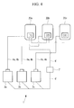
Fig. 4 }
Fig. 4 is a schematic diagram showing the configuration of a hot-water supply system according to a second embodiment of the present invention. - Hot-water supply systems and methods of controlling the same according to embodiments of the present invention will be described below with reference to the drawings.
- This embodiment will be described in the context of an example where a hot-water supply system according to the present invention is a commercial/industrial-use EcoCute (registered trademark) system that can supply an amount of hot water adequate for a large-scale facility by using a heat source device (heat pump unit) utilizing natural CO2 refrigerant in combination with a hot-water storage unit. However, the present invention is not limited to this example.
- As shown in
Fig. 1 , the hot-water supply unit 1 includes aheat source device 3, a hot-water storage unit 2,water pipes electrical wires communication line 6, an interface unit (interface means) 7, and a temperature detecting unit (temperature detecting means) 8. - In the
heat source device 3, the CO2 refrigerant absorbs heat in the air, the refrigerant is compressed by a compressor to raise its temperature, and heat is transferred from the high-temperature refrigerant to boil water to a specified temperature. Theheat source device 3 in this embodiment is a supercritical-cycle heat pump filled with CO2 refrigerant as a working medium, and this heat pump itself may be a known heat pump. Furthermore, although a supercritical-cycle heat pump utilizing CO2 refrigerant is described here as an example of theheat source device 3, theheat source device 3 need not necessarily be implemented by a heat pump in this embodiment and may instead be implemented by other equipment, such as a boiler or a fuel cell. - The
heat source device 3 is connected to thewater pipe 4a for introducing water that is supplied from the side of the hot-water storage unit 2 and to thewater pipe 4b for discharging high-temperature water. Theheat source device 3 heats low-temperature water supplied from thewater pipe 4a and supplies the heated high-temperature water (e.g., about 60 to 70 °C, hereinafter also referred to as "hot water") to thewater pipe 4b. - The
water pipe 4c is a hot-water supply path for supplying hot water stored in a hot-water storage tank 20 to a supply destination. - The
water pipe 4d is a path through which the hot water discharged from theheat source device 3 is introduced to the bottom side of the hot-water storage tank 20 in the case where the temperature of the discharged hot water is below a desired temperature (specified temperature), whereby the hot water is bypassed to thewater pipe 4e. - The
water pipe 4e is a pipe for supplying low-temperature water to the hot-water storage tank 20 and is connected to a water supply. - The hot-
water storage unit 2 includes the hot-water storage tank 20 and hot-water-stored-amount detecting units (hot-water-stored-amount detecting means) 21a, 21b ..., and 21n. Unless explicitly specified, these hot-water-stored-amount detecting units will be simply referred to as hot-water-stored-amount detecting units 21. - The hot-
water storage tank 20 receives water (e.g., 10 °C) from the water supply via thewater pipe 4e and also receives hot water (e.g., about 60 to 70 °C) heated by theheat source device 3 from the top side via thewater pipe 4b. Thus, temperature layers constituted of water on the lower side and the hot water on the upper side are formed in the hot-water storage tank 20. The hot-water-stored-amount detecting units 21 are provided in the hot-water storage tank 20 and detect the boundary between the temperature layers. - The multiple hot-water-stored-amount detecting units 21 are provided in the hot-
water storage tank 20 and detect the amount of hot water stored in the hot-water storage tank 20, which stores hot water heated by theheat source device 3. For example, thermistors that serve as temperature sensors are provided along the vertical direction (top-bottom direction) to constitute the hot-water-stored-amount detecting units amount detecting units amount detecting unit 21a is a temperature sensor installed at a position corresponding to 100% of the hot-water storage capacity. Furthermore, for example, the hot-water-stored-amount detecting unit 21b is a temperature sensor installed at a position corresponding to 90% of the hot-water storage capacity, and the hot-water-stored-amount detecting unit 21n is a temperature sensor installed at a position corresponding to 10% of the hot-water storage capacity. - Information about the temperatures detected by the individual hot-water-stored-amount detecting units (temperature sensors) 21a, 21b, ..., and 21n is output to the
interface unit 7. Furthermore, when the information about the temperatures detected by the individual temperature sensors is output to the control unit 30 (described later in detail), thecontrol unit 30 is able to detect the boundary of the temperature and detect the amount of stored hot water based on the position of the temperature sensor that has detected the temperature at the boundary. The thermistors have characteristics such that their resistances decrease as the temperatures become higher and their resistances increase as the temperatures become lower. - Although nine hot-water-stored-amount detecting units 21 are provided in this embodiment as an example, the number of the hot-water-stored-amount detecting units 21 is not particularly limited.
- The electrical valve 9 is provided in the path of the
water pipe 4b for supplying hot water heated by theheat source device 3 to the hot-water storage tank 20 and adjusts the flow level of the hot water supplied to the hot-water storage tank 20 according to a control signal. More specifically, the electrical valve 9 is controlled so as to distribute hot water to thewater pipe 4d connected to the bottom of the hot-water storage tank 20 according to the control signal output from thecontrol unit 30 in the case where the temperature of the hot water discharged from theheat source device 3 is below a desired temperature. The electrical valve 9 is controlled so as to distribute hot water to thewater pipe 4b connected to the top of the hot-water storage tank 20 according to the control signal output from thecontrol unit 30 in the case where the temperature of the hot water discharged from theheat source device 3 is at or above the desired temperature. - Although the distance between the
heat source device 3 and the hot-water storage tank 20 of the hot-water storage unit 2 is 100 m in this embodiment, there is no limitation as to the distance. - The
interface unit 7 is connected to the hot-water-stored-amount detecting units 21 via anelectrical wire 5a and obtains information about the amount of stored hot water detected by the hot-water-stored-amount detecting units 21. Theinterface unit 7 is also connected to the electrical valve 9 via anelectrical wire 5b to allow input and output of a degree-of-opening signal of the electrical valve 9. Theinterface unit 7 is provided in the vicinity of the hot-water storage tank 20, but its position is not particularly limited. - The
interface unit 7 is connected to thecontrol unit 30 via acommunication line 6. Theinterface unit 7 converts the information about the amount of stored hot water and the degree-of-opening signal of the electrical valve 9 input via theelectrical wires control unit 30 and outputs these signals to thecontrol unit 30 via thecommunication line 6. Theinterface unit 7 also converts the control signal obtained from thecontrol unit 30 via thecommunication line 6 into a signal that can be sent to and received from the electrical valve 9 and outputs the signal to the electrical valve 9 via theelectrical wire 5b. - The
heat source device 3 includes the control unit (controlling means) 30. - The
control unit 30 is connected such that information can be sent to and received from various devices provided in theheat source device 3, the temperature detecting unit (temperature detecting means) 8, the electrical valve 9, etc. and outputs control signals to these devices, etc. - For example, as shown in
Fig. 2 , thecontrol unit 30 is implemented by a microcomputer whose main components include a central processing unit (CPU) 33 that executes programs, amain memory 34 such as a random access memory (RAM) that temporarily stores the results of computation by theCPU 33, etc., anauxiliary storage device 35 that stores the programs executed by theCPU 33, an input andoutput interface 36 such as a digital I/O, and acommunication interface 37. - The
control unit 30 is connected to an instruction input device such as aremote controller 10. Thecontrol unit 30 obtains information about the specified temperature (requested temperature) and the requested amount of hot water to be stored in the hot-water storage tank 20 input via theremote controller 10 by a user of the hot-water supply system 1. - During the operation of the hot-
water supply system 1, thecontrol unit 30 controls the hot-water producing level to produce high-temperature water at the specified temperature (requested temperature) by controlling the rotation rates of a compressor and a water pump (not shown) of theheat source device 3 based on values detected by temperature sensors (not shown) individually installed on the side of thewater pipe 4a for introducing low-temperature water and on the side of thewater pipe 4b for discharging high-temperature water. Furthermore, during the operation of the hot-water supply system 1, thecontrol unit 30 controls the activation and deactivation of theheat source device 3 and the water pump for the purpose of what are called routine boiling and additional boiling based on values detected by the hot-water-stored-amount detecting units - The
control unit 30 is provided in theheat source device 3 and controls theheat source device 3 based on the information about the amount of stored hot water detected by the hot-water-stored-amount detecting units 21 and the degree-of-opening signal of the electrical valve 9. More specifically, thecontrol unit 30 has a first connector (first connecting means) 31 that allows connection such that information can be sent to and received from theinterface unit 7 via thecommunication line 6. When the control unit is connected to theinterface unit 7 via thecommunication line 6, thecontrol unit 30 obtains, via thecommunication line 6, the information about the amount of stored hot water and the degree-of-opening signal of the electrical valve 9 that have been converted by theinterface unit 7 into the format that can be sent and received via thecommunication line 6. - Furthermore, the
control unit 30 may have a second connector (second connecting means) 32a that makes it possible to send information to and receive information from the hot-water-stored-amount detecting units 21 via theelectrical wire 5a without the involvement of theinterface unit 7 and a third connector (third connecting means) 32b that makes it possible to send information to and receive information from the electrical valve 9 via theelectrical wire 5b without the involvement of theinterface unit 7. This makes it possible to apply the present invention to an existing hot-water storage tank and to a hot-water supply system not equipped with theinterface unit 7. - The
control unit 30 detects the boundary of the temperature between hot water and cold water in the hot-water storage tank 20 based on information about the temperatures at the individual temperature sensors detected by the hot-water-stored-amount detecting units 21, thereby estimating the amount of hot water stored in the hot-water storage tank 20. - The temperature detecting unit 8 is installed in the vicinity of the inlet for hot water that flows into the hot-
water storage tank 20. The temperature detecting unit 8 detects the temperature of the pipe at the inlet of the hot-water storage tank 20 and outputs information about the detected temperature to thecontrol unit 30. In this embodiment, the temperature detecting unit 8 detects the temperature of the pipe instead of detecting the temperature of the fluid (hot water) flowing through the pipe. For example, the temperature detecting unit 8 is a thermistor that serves as a temperature sensor. - Although it is assumed here that the temperature detecting unit 8 and the
control unit 30 are connected to each other via theinterface unit 7, without limitation to this configuration, the temperature detecting unit 8 and thecontrol unit 30 may be connected to each other directly without theinterface unit 7 being provided in between. More specifically, in the case where theinterface unit 7 is provided in between, the temperature detecting unit 8 and theinterface unit 7 are connected to each other via an electrical wire, and theinterface unit 7 and thecontrol unit 30 are connected to each other via a communication line. In the case where theinterface unit 7 is not provided in between, the temperature detecting unit 8 and thecontrol unit 30 are connected to each other via an electrical wire. - Upon obtaining the information about the temperature at the inlet of the hot-
water storage tank 20 from the temperature detecting unit 8, thecontrol unit 30 controls the compressor and water pump of theheat source device 3 based on the detected temperature. By thus controlling theheat source device 3 in accordance with the temperature at the inlet of the hot-water storage tank 20, it is possible to supply hot water of a desired temperature to the hot-water storage tank 20 in consideration of heat dissipation even in the case where theheat source device 3 and the hot-water storage tank 20 are remote from each other. - The operation of the hot-
water supply system 1 according to the present invention will be described below. - A user of the hot-
water supply system 1 operates theremote controller 10 to enter information about the specified temperature (requested temperature) at the tap side (the point where hot water is supplied from thewater pipe 4c, e.g., the point of usage for a shower, a cleaning line, etc.) and/or the amount of hot water stored in the hot-water storage tank 20. - Water is supplied from the water supply to the hot-
water storage tank 20 via thewater pipe 4e. The water supplied from the hot-water storage tank 20 to theheat source device 3 via thewater pipe 4a is heated by theheat source device 3 to become hot water (e.g., 70 °C), and the hot water heated by theheat source device 3 is discharged to thewater pipe 4b. - The electrical valve 9 is controlled so that the hot water discharged from the
heat source device 3 is supplied from thewater pipe 4b to the hot-water storage tank 20 from the bottom of the hot-water storage tank 20 via thewater pipe 4d until the temperature of the hot water discharged from theheat source device 3 reaches the specified temperature (requested temperature). When the temperature of the hot water heated by theheat source device 3 reaches the specified temperature, the electrical valve 9 is controlled so that the hot water discharged from theheat source device 3 is flowed into thewater pipe 4b connected to the top of the hot-water storage tank 20 from thewater pipe 4b via the electrical valve 9, whereby the hot water is supplied to the hot-water storage tank 20 from the top of the hot-water storage tank 20. - The temperature information detected by the multiple temperature sensors that detect the amount of stored hot water is output to the
interface unit 7 via theelectrical wire 5a. Furthermore, the degree-of-opening signal of the electrical valve 9 is output to theinterface unit 7 via theelectrical wire 5b. - The information about the amount of stored hot water (temperature information) and the degree-of-opening signal of the electrical valve 9, obtained via the
electrical wires communication line 6. The information about the amount of stored hot water and the degree-of-opening signal of the electrical valve 9, converted by theinterface unit 7, are sent to thecontrol unit 30 via thecommunication line 6 interconnecting theinterface unit 7 and thecontrol unit 30. - The
control unit 30 detects the boundary of the temperature in the hot-water storage tank 20 based on information about the temperatures individually detected by the multiple temperature sensors and estimates the amount of stored hot water by considering that the vicinity of the position of the temperature sensor detected as the boundary of the temperature is the interface between temperature layers. In the case where the estimated amount of stored hot water has not reached the amount of stored hot water requested by the user (remote controller), the water continues to be heated by the hot-water storage tank 20, and water is supplied repeatedly until the requested amount of stored hot water is reached. - Furthermore, the degree-of-opening signal of the electrical valve 9 is fed back to the
control unit 30. Thecontrol unit 30 controls theheat source device 3 as needed and controls the electrical valve 9 based on the temperature of the hot water discharged from theheat source device 3 and the specified temperature at the hot-water supply side. - Furthermore, the temperature of the pipe at the inlet of the hot-
water storage tank 20 is detected in the vicinity of the inlet of the hot-water storage tank 20, and information about the detected temperature is output to thecontrol unit 30. - The
heat source device 3 is controlled based on the temperature of the pipe in the vicinity of the inlet of the hot-water storage tank 20 so that the specified temperature will be reached on the tap side. - For example, in the case where the specified temperature (at the
water pipe 4c) requested by the user is 70 °C, theheat source device 3 is controlled so that the temperature of the hot water discharged from theheat source device 3 to thewater pipe 4b becomes 70 °C. In the case where the distance between theheat source device 3 and the hot-water storage tank 20 is long (e.g., 100 m), the temperature of the hot water flowing through thewater pipe 4b drops due to heat dissipation in the path of thewater pipe 4b, and the temperature of the pipe at the temperature detecting unit 8 sometimes drops to about 65 °C. Thus, the temperature of the pipe detected by the temperature detecting unit 8 is fed back to thecontroller 30, the temperature of the hot water discharged from theheat source device 3 is set to 75 °C so that the temperature of the pipe at the temperature detecting unit 8 will reach the temperature specified by the user in view of heat dissipation in thewater pipe 4b, and theheat source device 3 is controlled accordingly. The temperature setting described here is only an example and does not limit the present invention. - As described hereinabove, with the hot-
water supply system 1 and a method of controlling the same according to the present invention, since theinterface unit 7 is provided between theheat source device 3 and the hot-water storage tank 20, theinterface unit 7 and theheat source device 3 are connected to each other via thecommunication line 6, and information about the amount of stored hot water and information about the degree-of-opening signal of the electrical valve 9 are input to theheat source device 3 via thecommunication line 6, even in the case where theheat source device 3 and the hot-water storage tank 20 are remote from each other, it is possible to deliver the information about the amount of stored hot water and the information about the degree-of-opening signal of the electrical valve 9 more reliably and accurately to theheat source device 3 compared with the case of extending electrical wires. - Furthermore, since the temperature detecting unit 8 is provided to feed back the temperature in the vicinity of the inlet of the hot-
water storage tank 20, even if theheat source device 3 and the hot-water storage tank 20 are remote from each other, it is possible to control theheat source device 3 in consideration of heat dissipation that occurs between theheat source device 3 and the hot-water storage tank 20. Thus, it is possible to obtain hot water at a desired temperature on the hot-water supply side. - The
control unit 30 has afirst connector 31 that allows connection with theinterface unit 7 via thecommunication line 6, asecond connector 32a that allows connection with the hot-water-stored-amount detecting units 21 via theelectrical wire 5a without theinterface unit 7 being provided in between, and athird connector 32b that allows connection with the electrical valve 9 via theelectrical wire 5b without theinterface unit 7 being provided in between. Thus, it is possible to apply the present invention, having theinterface 7, in an environment where the hot-water storage tank 20 and theheat source device 3 are remote from each other (20 m or more), and it is also possible to apply the present invention to an existing hot-water supply system. - Furthermore, as shown in
Fig. 1 , although the number of electrical wires increases with the number of hot-water-stored-amount detecting units provided in the hot-water storage tank 20, which makes the wiring complex, theinterface unit 7 serves to reduce this complexity since it suffices to provide theelectrical wires interface unit 7. - Although the hot-
water storage tank 20 that has been described as an example is of the closed type, the type of tank used in the present invention is not limited to this example. For example, the tank may be atank 22 of the open type, as shown inFig. 3 . In order to simplify the drawing, the vicinity of the hot-water storage tank 22 is shown as enlarged, and parts that are common to those in the embodiment described above are omitted. Thewater pipes water pipes Fig. 1 , respectively. - Furthermore, as shown in
Fig. 3 , theopen tank 22 may have one temperature sensor A (that detects the temperature) and one water-level sensor B (that detects the water pressure). - The temperature sensor A and the water-level sensor B individually output their detected sensor values to the
control unit 30, and thecontrol unit 30 detects the amount of hot water stored. For example, the water-level sensor B is installed in the vicinity of the bottom of the tank as a hot-water-stored-amount detecting unit, and the water level in the state where the hot-water storage tank is fully filled with hot water is defined in advance as 100%. This makes it possible to ascertain the amount of stored hot water based on changes in the water level. - Similarly to the embodiment described above, the temperature sensor A and the water-level sensor B may be connected to the
control unit 30 either by means of thecommunication line 6 via theinterface unit 7 or by means of electrical wires without theinterface unit 7 being provided in between. - A second embodiment of the present invention will be described below with reference to
Fig. 4 . A hot-water supply system 1' according to the second embodiment differs from the hot-water supply system 1 according to the first embodiment in that multiple heat source devices and multiple hot-water storage tanks are provided and in that an interface unit and the hot-water storage tanks are connected to each other also via a communication line. The following description will be directed mainly to differences, while omitting description about commonalities with the first embodiment. Furthermore, parts that are common to those shown inFig. 1 are denoted by the same reference signs. - A
heat source device 3a is connected to a hot-water storage tank 20a viawater pipes heat source device 3b is connected to a hot-water storage tank 20b viawater pipes heat source device 3c is connected to a hot-water storage tank 20c viawater pipes water pipes Fig. 1 . - An interface unit 7' is connected to the
heat source devices water storage tanks - The interface unit 7' has an address setting function for assigning hot-water-storage-tank addresses [1], [2], and [3] for identifying the associated hot-water storage tanks to the individual
heat source devices - Thus, when the interface unit 7' obtains information about the amounts of stored hot water detected by the hot-water-stored-amount detecting units for the individual hot-
water storage tanks water storage tanks heat source devices heat source devices -
- 1
- hot-water supply system
- 2
- hot-water storage unit
- 3, 3a, 3b, 3c
- heat source device
- 4a, 4b, 4c, 4d, 4e
- water pipe
- 5a, 5b
- electrical wire
- 6, 6'
- communication line
- 7, 7'
- interface unit
- 8
- temperature detecting unit
- 9
- electrical valve
- 20, 20a, 20b, 20c
- hot-water storage tank (closed type)
- 21a, 21b ..., 21n
- hot-water-stored-amount detecting unit
- 22
- open-type tank
- 30
- control unit
- 31
- first connector
- 32a
- second connector
- 32b
- third connector
- A
- temperature sensor
- B
- water-level sensor
Claims (5)
- A hot-water supply system (1) comprising:a heat source device (3);a hot-water-stored-amount detecting means (21a,21b,...21n) configured to detect an amount of hot water stored in a hot-water storage tank (20) configured to store hot water heated by the heat source device (3);an electrical valve (9) that is provided in a path of supplying the hot water heated by the heat source device (3) to the hot-water storage tank (20) and that is configured to adjust a flow level of hot water supplied to the hot-water storage tank (20) according to a control signal;a controlling means (30) that is provided in the heat source device (3) and that is configured to control the heat source device (3) based on information about the amount of stored hot water detected by the hot-water-stored-amount detecting means (21a,21b,...21n) and based on a degree-of-opening signal of the electrical valve (9); andan interface means (7) that is connected to the hot-water-stored-amount detecting means (21a,21b,...21n) and the electrical valve (9) via electrical wires (5a,5b) so that the information about the amount of stored hot water detected by the hot-water-stored-amount detecting means and the degree-of-opening signal of the electrical valve (9) can be input and output via the electrical wires, and that is also connected to the controlling means (30) via a communication line (6) and that is configured to convert the information about the amount of stored hot water and the degree-of-opening signal of the electrical valve input and output via the electrical wires (5a,5b) into signals that can be sent to and received from the controlling means (30) via the communication line (6),wherein the controlling means (30) includes a first connecting means (31) configured to allow connection with the interface means (7) so that information can be sent and received via the communication line (6).
- A hot-water supply system according to Claim 1, wherein the controlling means (30) includes a second connecting means (32a) configured to make it possible to send information to and receive information from the hot-water-stored-amount detecting means via the electrical wires (5a,5b) and a third connecting means (32b) configured to make it possible to send information to and receive information from the electrical valve via the electrical wires (5a,5b).
- A hot-water supply system according to Claim 1 or 2, further comprising a temperature detecting means (8) that is installed in the vicinity of an inlet for hot water that flows into the hot-water storage tank (20), that is configured to detect the temperature at the inlet of the hot-water storage tank, and that outputs information about the detected temperature to the controlling means (30),
wherein the controlling means (30) is configured to control the heat source device based on the temperature detected by the temperature detecting means (8). - A hot-water supply system according to any one of Claims 1 to 3, comprising
a plurality of heat source devices (3,3a,3b,3c) including the heat source device (3) and a plurality of hot-water storage tanks (20,20a,20b,20c) including the hot-water storage tank (20), wherein
the interface means (7) and the hot-water storage tanks are connected via the communication line (6), and
the interface means (7) has an address setting function for assigning hot-water-storage tank addresses for identifying the associate hot-water storage tanks to the individual heat source devices. - A method of controlling a hot-water supply system, comprising:a first step of detecting an amount of hot water stored in a hot-water storage tank (20) that stores hot water heated by a heat source device (3);a second step of adjusting a flow level of hot water supplied to the hot-water storage tank according to a control signal for an electrical valve (9) that is provided in a path of supplying hot water heated by the heat source device (3) to the hot-water storage tank (20);a third step of controlling the heat source device (3) at the side of the heat source device based on information about the amount of stored hot water detected and a degree-of-opening signal of the electrical valve (9); anda fourth step of inputting and outputting the information about the amount of stored hot water detected in the first step and the degree-of-opening signal of the electrical valve via electrical wires (5a,5b) and converting the information about the amount of stored hot water and the degree-of-opening signal of the electrical valve input and output via the electrical wires into signals that can be sent and received via a communication line (6).
Applications Claiming Priority (1)
| Application Number | Priority Date | Filing Date | Title |
|---|---|---|---|
| JP2014053369A JP6400310B2 (en) | 2014-03-17 | 2014-03-17 | Hot water supply system and control method thereof |
Publications (3)
| Publication Number | Publication Date |
|---|---|
| EP2921789A1 true EP2921789A1 (en) | 2015-09-23 |
| EP2921789B1 EP2921789B1 (en) | 2017-11-08 |
| EP2921789B8 EP2921789B8 (en) | 2017-12-27 |
Family
ID=52684042
Family Applications (1)
| Application Number | Title | Priority Date | Filing Date |
|---|---|---|---|
| EP15158680.7A Active EP2921789B8 (en) | 2014-03-17 | 2015-03-11 | Hot-water supply system and method of controlling the same |
Country Status (2)
| Country | Link |
|---|---|
| EP (1) | EP2921789B8 (en) |
| JP (1) | JP6400310B2 (en) |
Families Citing this family (1)
| Publication number | Priority date | Publication date | Assignee | Title |
|---|---|---|---|---|
| JP2017051247A (en) * | 2015-09-07 | 2017-03-16 | 京楽産業.株式会社 | Game machine |
Citations (7)
| Publication number | Priority date | Publication date | Assignee | Title |
|---|---|---|---|---|
| EP1898160A1 (en) * | 2006-08-30 | 2008-03-12 | Uwe Wendler | Method for controlling a heating system and heating system for carying out said method |
| EP2085706A2 (en) * | 2008-02-01 | 2009-08-05 | Daikin Industries, Ltd. | Hot water storage type heat pump unit |
| EP2151578A1 (en) * | 2008-08-04 | 2010-02-10 | Grundfos Management A/S | Circulation pump system |
| US20100083950A1 (en) * | 2008-09-25 | 2010-04-08 | Bloxam Michael J | Solar energy water heating system |
| EP2213949A2 (en) * | 2009-01-30 | 2010-08-04 | Panasonic Corporation | Liquid circulation heating system |
| US20110282498A1 (en) * | 2010-05-11 | 2011-11-17 | FLS Solar Technologies, Inc. | Solar thermal data acquisition systems and methods and systems using the same |
| JP2012149795A (en) | 2011-01-18 | 2012-08-09 | Corona Corp | Heat pump water heater |
Family Cites Families (2)
| Publication number | Priority date | Publication date | Assignee | Title |
|---|---|---|---|---|
| JP2008116131A (en) * | 2006-11-06 | 2008-05-22 | Sanden Corp | Freezing prevention device for water heater |
| JP5796707B2 (en) * | 2011-08-26 | 2015-10-21 | 株式会社ノーリツ | Heat pump heat source machine |
-
2014
- 2014-03-17 JP JP2014053369A patent/JP6400310B2/en active Active
-
2015
- 2015-03-11 EP EP15158680.7A patent/EP2921789B8/en active Active
Patent Citations (7)
| Publication number | Priority date | Publication date | Assignee | Title |
|---|---|---|---|---|
| EP1898160A1 (en) * | 2006-08-30 | 2008-03-12 | Uwe Wendler | Method for controlling a heating system and heating system for carying out said method |
| EP2085706A2 (en) * | 2008-02-01 | 2009-08-05 | Daikin Industries, Ltd. | Hot water storage type heat pump unit |
| EP2151578A1 (en) * | 2008-08-04 | 2010-02-10 | Grundfos Management A/S | Circulation pump system |
| US20100083950A1 (en) * | 2008-09-25 | 2010-04-08 | Bloxam Michael J | Solar energy water heating system |
| EP2213949A2 (en) * | 2009-01-30 | 2010-08-04 | Panasonic Corporation | Liquid circulation heating system |
| US20110282498A1 (en) * | 2010-05-11 | 2011-11-17 | FLS Solar Technologies, Inc. | Solar thermal data acquisition systems and methods and systems using the same |
| JP2012149795A (en) | 2011-01-18 | 2012-08-09 | Corona Corp | Heat pump water heater |
Also Published As
| Publication number | Publication date |
|---|---|
| JP2015175563A (en) | 2015-10-05 |
| EP2921789B1 (en) | 2017-11-08 |
| EP2921789B8 (en) | 2017-12-27 |
| JP6400310B2 (en) | 2018-10-03 |
Similar Documents
| Publication | Publication Date | Title |
|---|---|---|
| US9664415B2 (en) | Hot-water heat pump and method of controlling the same | |
| CN105229310B (en) | Circulate pump assembly and solar-heating equipment | |
| EP3412985A1 (en) | Method for controlling water-heating system, and water-heating system | |
| CN102119278A (en) | Circulating pump unit | |
| CN103953964B (en) | Gas heating hot water furnace parallel connection heat supply system | |
| KR20130119349A (en) | Storage type hot water supply device | |
| CN103270375B (en) | Straight-through heater | |
| CN103868243B (en) | Water temperature control method of hot water system and hot water system | |
| US10801751B2 (en) | Water consuming appliance and a method for operating the same | |
| KR20150106831A (en) | Heat source device controller and air conditioning system | |
| EP2921789B1 (en) | Hot-water supply system and method of controlling the same | |
| EP3540324B1 (en) | Heating medium circulation system | |
| EP2985535A1 (en) | Fluid-heating system | |
| CN106766130A (en) | The control method and control system of hot water storage tank and hot water storage tank | |
| CN105066433A (en) | Hot-water system, constant-temperature device and control method of constant-temperature device | |
| EP4055328B1 (en) | Method and control unit for controlling a control valve controlling a flow of heat transfer fluid into a thermal energy extraction unit | |
| JP6137666B2 (en) | Hot water system | |
| EP3779285A1 (en) | Heating system | |
| JP6225630B2 (en) | Hot water system | |
| US20250102153A1 (en) | Hot-water supply apparatus | |
| JP2006234248A (en) | Heat pump type hot water supply device | |
| JP5746564B2 (en) | Reduction amount calculation apparatus and sensor abnormality detection method thereof | |
| JP5178115B2 (en) | Hot water storage water heater | |
| JP6146317B2 (en) | Fuel gas tank mounting device | |
| JP5161628B2 (en) | Hot water system |
Legal Events
| Date | Code | Title | Description |
|---|---|---|---|
| PUAI | Public reference made under article 153(3) epc to a published international application that has entered the european phase |
Free format text: ORIGINAL CODE: 0009012 |
|
| AK | Designated contracting states |
Kind code of ref document: A1 Designated state(s): AL AT BE BG CH CY CZ DE DK EE ES FI FR GB GR HR HU IE IS IT LI LT LU LV MC MK MT NL NO PL PT RO RS SE SI SK SM TR |
|
| AX | Request for extension of the european patent |
Extension state: BA ME |
|
| 17P | Request for examination filed |
Effective date: 20160322 |
|
| RBV | Designated contracting states (corrected) |
Designated state(s): AL AT BE BG CH CY CZ DE DK EE ES FI FR GB GR HR HU IE IS IT LI LT LU LV MC MK MT NL NO PL PT RO RS SE SI SK SM TR |
|
| GRAP | Despatch of communication of intention to grant a patent |
Free format text: ORIGINAL CODE: EPIDOSNIGR1 |
|
| INTG | Intention to grant announced |
Effective date: 20170622 |
|
| GRAS | Grant fee paid |
Free format text: ORIGINAL CODE: EPIDOSNIGR3 |
|
| GRAA | (expected) grant |
Free format text: ORIGINAL CODE: 0009210 |
|
| AK | Designated contracting states |
Kind code of ref document: B1 Designated state(s): AL AT BE BG CH CY CZ DE DK EE ES FI FR GB GR HR HU IE IS IT LI LT LU LV MC MK MT NL NO PL PT RO RS SE SI SK SM TR |
|
| REG | Reference to a national code |
Ref country code: GB Ref legal event code: FG4D |
|
| REG | Reference to a national code |
Ref country code: CH Ref legal event code: EP Ref country code: AT Ref legal event code: REF Ref document number: 944496 Country of ref document: AT Kind code of ref document: T Effective date: 20171115 |
|
| REG | Reference to a national code |
Ref country code: IE Ref legal event code: FG4D |
|
| RAP2 | Party data changed (patent owner data changed or rights of a patent transferred) |
Owner name: MITSUBISHI HEAVY INDUSTRIES THERMAL SYSTEMS, LTD. |
|
| REG | Reference to a national code |
Ref country code: DE Ref legal event code: R096 Ref document number: 602015005781 Country of ref document: DE |
|
| REG | Reference to a national code |
Ref country code: NL Ref legal event code: MP Effective date: 20171108 |
|
| REG | Reference to a national code |
Ref country code: FR Ref legal event code: PLFP Year of fee payment: 4 |
|
| REG | Reference to a national code |
Ref country code: LT Ref legal event code: MG4D |
|
| REG | Reference to a national code |
Ref country code: AT Ref legal event code: MK05 Ref document number: 944496 Country of ref document: AT Kind code of ref document: T Effective date: 20171108 |
|
| PG25 | Lapsed in a contracting state [announced via postgrant information from national office to epo] |
Ref country code: LT Free format text: LAPSE BECAUSE OF FAILURE TO SUBMIT A TRANSLATION OF THE DESCRIPTION OR TO PAY THE FEE WITHIN THE PRESCRIBED TIME-LIMIT Effective date: 20171108 Ref country code: SE Free format text: LAPSE BECAUSE OF FAILURE TO SUBMIT A TRANSLATION OF THE DESCRIPTION OR TO PAY THE FEE WITHIN THE PRESCRIBED TIME-LIMIT Effective date: 20171108 Ref country code: NO Free format text: LAPSE BECAUSE OF FAILURE TO SUBMIT A TRANSLATION OF THE DESCRIPTION OR TO PAY THE FEE WITHIN THE PRESCRIBED TIME-LIMIT Effective date: 20180208 Ref country code: ES Free format text: LAPSE BECAUSE OF FAILURE TO SUBMIT A TRANSLATION OF THE DESCRIPTION OR TO PAY THE FEE WITHIN THE PRESCRIBED TIME-LIMIT Effective date: 20171108 Ref country code: NL Free format text: LAPSE BECAUSE OF FAILURE TO SUBMIT A TRANSLATION OF THE DESCRIPTION OR TO PAY THE FEE WITHIN THE PRESCRIBED TIME-LIMIT Effective date: 20171108 Ref country code: FI Free format text: LAPSE BECAUSE OF FAILURE TO SUBMIT A TRANSLATION OF THE DESCRIPTION OR TO PAY THE FEE WITHIN THE PRESCRIBED TIME-LIMIT Effective date: 20171108 |
|
| PG25 | Lapsed in a contracting state [announced via postgrant information from national office to epo] |
Ref country code: LV Free format text: LAPSE BECAUSE OF FAILURE TO SUBMIT A TRANSLATION OF THE DESCRIPTION OR TO PAY THE FEE WITHIN THE PRESCRIBED TIME-LIMIT Effective date: 20171108 Ref country code: HR Free format text: LAPSE BECAUSE OF FAILURE TO SUBMIT A TRANSLATION OF THE DESCRIPTION OR TO PAY THE FEE WITHIN THE PRESCRIBED TIME-LIMIT Effective date: 20171108 Ref country code: AT Free format text: LAPSE BECAUSE OF FAILURE TO SUBMIT A TRANSLATION OF THE DESCRIPTION OR TO PAY THE FEE WITHIN THE PRESCRIBED TIME-LIMIT Effective date: 20171108 Ref country code: RS Free format text: LAPSE BECAUSE OF FAILURE TO SUBMIT A TRANSLATION OF THE DESCRIPTION OR TO PAY THE FEE WITHIN THE PRESCRIBED TIME-LIMIT Effective date: 20171108 Ref country code: BG Free format text: LAPSE BECAUSE OF FAILURE TO SUBMIT A TRANSLATION OF THE DESCRIPTION OR TO PAY THE FEE WITHIN THE PRESCRIBED TIME-LIMIT Effective date: 20180208 Ref country code: IS Free format text: LAPSE BECAUSE OF FAILURE TO SUBMIT A TRANSLATION OF THE DESCRIPTION OR TO PAY THE FEE WITHIN THE PRESCRIBED TIME-LIMIT Effective date: 20180308 Ref country code: GR Free format text: LAPSE BECAUSE OF FAILURE TO SUBMIT A TRANSLATION OF THE DESCRIPTION OR TO PAY THE FEE WITHIN THE PRESCRIBED TIME-LIMIT Effective date: 20180209 |
|
| PG25 | Lapsed in a contracting state [announced via postgrant information from national office to epo] |
Ref country code: CZ Free format text: LAPSE BECAUSE OF FAILURE TO SUBMIT A TRANSLATION OF THE DESCRIPTION OR TO PAY THE FEE WITHIN THE PRESCRIBED TIME-LIMIT Effective date: 20171108 Ref country code: SK Free format text: LAPSE BECAUSE OF FAILURE TO SUBMIT A TRANSLATION OF THE DESCRIPTION OR TO PAY THE FEE WITHIN THE PRESCRIBED TIME-LIMIT Effective date: 20171108 Ref country code: DK Free format text: LAPSE BECAUSE OF FAILURE TO SUBMIT A TRANSLATION OF THE DESCRIPTION OR TO PAY THE FEE WITHIN THE PRESCRIBED TIME-LIMIT Effective date: 20171108 Ref country code: CY Free format text: LAPSE BECAUSE OF FAILURE TO SUBMIT A TRANSLATION OF THE DESCRIPTION OR TO PAY THE FEE WITHIN THE PRESCRIBED TIME-LIMIT Effective date: 20171108 Ref country code: EE Free format text: LAPSE BECAUSE OF FAILURE TO SUBMIT A TRANSLATION OF THE DESCRIPTION OR TO PAY THE FEE WITHIN THE PRESCRIBED TIME-LIMIT Effective date: 20171108 |
|
| REG | Reference to a national code |
Ref country code: DE Ref legal event code: R097 Ref document number: 602015005781 Country of ref document: DE |
|
| PG25 | Lapsed in a contracting state [announced via postgrant information from national office to epo] |
Ref country code: PL Free format text: LAPSE BECAUSE OF FAILURE TO SUBMIT A TRANSLATION OF THE DESCRIPTION OR TO PAY THE FEE WITHIN THE PRESCRIBED TIME-LIMIT Effective date: 20171108 Ref country code: RO Free format text: LAPSE BECAUSE OF FAILURE TO SUBMIT A TRANSLATION OF THE DESCRIPTION OR TO PAY THE FEE WITHIN THE PRESCRIBED TIME-LIMIT Effective date: 20171108 Ref country code: SM Free format text: LAPSE BECAUSE OF FAILURE TO SUBMIT A TRANSLATION OF THE DESCRIPTION OR TO PAY THE FEE WITHIN THE PRESCRIBED TIME-LIMIT Effective date: 20171108 |
|
| PLBE | No opposition filed within time limit |
Free format text: ORIGINAL CODE: 0009261 |
|
| STAA | Information on the status of an ep patent application or granted ep patent |
Free format text: STATUS: NO OPPOSITION FILED WITHIN TIME LIMIT |
|
| 26N | No opposition filed |
Effective date: 20180809 |
|
| REG | Reference to a national code |
Ref country code: CH Ref legal event code: PL |
|
| PG25 | Lapsed in a contracting state [announced via postgrant information from national office to epo] |
Ref country code: SI Free format text: LAPSE BECAUSE OF FAILURE TO SUBMIT A TRANSLATION OF THE DESCRIPTION OR TO PAY THE FEE WITHIN THE PRESCRIBED TIME-LIMIT Effective date: 20171108 Ref country code: MC Free format text: LAPSE BECAUSE OF FAILURE TO SUBMIT A TRANSLATION OF THE DESCRIPTION OR TO PAY THE FEE WITHIN THE PRESCRIBED TIME-LIMIT Effective date: 20171108 |
|
| REG | Reference to a national code |
Ref country code: BE Ref legal event code: MM Effective date: 20180331 |
|
| REG | Reference to a national code |
Ref country code: IE Ref legal event code: MM4A |
|
| PG25 | Lapsed in a contracting state [announced via postgrant information from national office to epo] |
Ref country code: LU Free format text: LAPSE BECAUSE OF NON-PAYMENT OF DUE FEES Effective date: 20180311 |
|
| PG25 | Lapsed in a contracting state [announced via postgrant information from national office to epo] |
Ref country code: IE Free format text: LAPSE BECAUSE OF NON-PAYMENT OF DUE FEES Effective date: 20180311 |
|
| PG25 | Lapsed in a contracting state [announced via postgrant information from national office to epo] |
Ref country code: BE Free format text: LAPSE BECAUSE OF NON-PAYMENT OF DUE FEES Effective date: 20180331 Ref country code: CH Free format text: LAPSE BECAUSE OF NON-PAYMENT OF DUE FEES Effective date: 20180331 Ref country code: LI Free format text: LAPSE BECAUSE OF NON-PAYMENT OF DUE FEES Effective date: 20180331 |
|
| GBPC | Gb: european patent ceased through non-payment of renewal fee |
Effective date: 20190311 |
|
| PG25 | Lapsed in a contracting state [announced via postgrant information from national office to epo] |
Ref country code: MT Free format text: LAPSE BECAUSE OF NON-PAYMENT OF DUE FEES Effective date: 20180311 Ref country code: GB Free format text: LAPSE BECAUSE OF NON-PAYMENT OF DUE FEES Effective date: 20190311 |
|
| PG25 | Lapsed in a contracting state [announced via postgrant information from national office to epo] |
Ref country code: TR Free format text: LAPSE BECAUSE OF FAILURE TO SUBMIT A TRANSLATION OF THE DESCRIPTION OR TO PAY THE FEE WITHIN THE PRESCRIBED TIME-LIMIT Effective date: 20171108 |
|
| PG25 | Lapsed in a contracting state [announced via postgrant information from national office to epo] |
Ref country code: PT Free format text: LAPSE BECAUSE OF FAILURE TO SUBMIT A TRANSLATION OF THE DESCRIPTION OR TO PAY THE FEE WITHIN THE PRESCRIBED TIME-LIMIT Effective date: 20171108 |
|
| PG25 | Lapsed in a contracting state [announced via postgrant information from national office to epo] |
Ref country code: HU Free format text: LAPSE BECAUSE OF FAILURE TO SUBMIT A TRANSLATION OF THE DESCRIPTION OR TO PAY THE FEE WITHIN THE PRESCRIBED TIME-LIMIT; INVALID AB INITIO Effective date: 20150311 Ref country code: MK Free format text: LAPSE BECAUSE OF NON-PAYMENT OF DUE FEES Effective date: 20171108 |
|
| PG25 | Lapsed in a contracting state [announced via postgrant information from national office to epo] |
Ref country code: AL Free format text: LAPSE BECAUSE OF FAILURE TO SUBMIT A TRANSLATION OF THE DESCRIPTION OR TO PAY THE FEE WITHIN THE PRESCRIBED TIME-LIMIT Effective date: 20171108 |
|
| REG | Reference to a national code |
Ref country code: DE Ref legal event code: R082 Ref document number: 602015005781 Country of ref document: DE Representative=s name: CBDL PATENTANWAELTE GBR, DE Ref country code: DE Ref legal event code: R082 Ref document number: 602015005781 Country of ref document: DE Representative=s name: CBDL PATENTANWAELTE EGBR, DE |
|
| PGFP | Annual fee paid to national office [announced via postgrant information from national office to epo] |
Ref country code: DE Payment date: 20260128 Year of fee payment: 12 |
|
| PGFP | Annual fee paid to national office [announced via postgrant information from national office to epo] |
Ref country code: IT Payment date: 20260220 Year of fee payment: 12 |
|
| PGFP | Annual fee paid to national office [announced via postgrant information from national office to epo] |
Ref country code: FR Payment date: 20260209 Year of fee payment: 12 |