EP2921659A1 - Exhaust-heat recovery system and exhaust-heat recovery method - Google Patents
Exhaust-heat recovery system and exhaust-heat recovery method Download PDFInfo
- Publication number
- EP2921659A1 EP2921659A1 EP13862912.6A EP13862912A EP2921659A1 EP 2921659 A1 EP2921659 A1 EP 2921659A1 EP 13862912 A EP13862912 A EP 13862912A EP 2921659 A1 EP2921659 A1 EP 2921659A1
- Authority
- EP
- European Patent Office
- Prior art keywords
- exhaust
- control valve
- flow
- engine
- turbine
- Prior art date
- Legal status (The legal status is an assumption and is not a legal conclusion. Google has not performed a legal analysis and makes no representation as to the accuracy of the status listed.)
- Granted
Links
Images


Classifications
-
- F—MECHANICAL ENGINEERING; LIGHTING; HEATING; WEAPONS; BLASTING
- F01—MACHINES OR ENGINES IN GENERAL; ENGINE PLANTS IN GENERAL; STEAM ENGINES
- F01N—GAS-FLOW SILENCERS OR EXHAUST APPARATUS FOR MACHINES OR ENGINES IN GENERAL; GAS-FLOW SILENCERS OR EXHAUST APPARATUS FOR INTERNAL-COMBUSTION ENGINES
- F01N5/00—Exhaust or silencing apparatus combined or associated with devices profiting by exhaust energy
- F01N5/02—Exhaust or silencing apparatus combined or associated with devices profiting by exhaust energy the devices using heat
-
- F—MECHANICAL ENGINEERING; LIGHTING; HEATING; WEAPONS; BLASTING
- F01—MACHINES OR ENGINES IN GENERAL; ENGINE PLANTS IN GENERAL; STEAM ENGINES
- F01K—STEAM ENGINE PLANTS; STEAM ACCUMULATORS; ENGINE PLANTS NOT OTHERWISE PROVIDED FOR; ENGINES USING SPECIAL WORKING FLUIDS OR CYCLES
- F01K23/00—Plants characterised by more than one engine delivering power external to the plant, the engines being driven by different fluids
- F01K23/02—Plants characterised by more than one engine delivering power external to the plant, the engines being driven by different fluids the engine cycles being thermally coupled
- F01K23/06—Plants characterised by more than one engine delivering power external to the plant, the engines being driven by different fluids the engine cycles being thermally coupled combustion heat from one cycle heating the fluid in another cycle
- F01K23/065—Plants characterised by more than one engine delivering power external to the plant, the engines being driven by different fluids the engine cycles being thermally coupled combustion heat from one cycle heating the fluid in another cycle the combustion taking place in an internal combustion piston engine, e.g. a diesel engine
-
- F—MECHANICAL ENGINEERING; LIGHTING; HEATING; WEAPONS; BLASTING
- F01—MACHINES OR ENGINES IN GENERAL; ENGINE PLANTS IN GENERAL; STEAM ENGINES
- F01N—GAS-FLOW SILENCERS OR EXHAUST APPARATUS FOR MACHINES OR ENGINES IN GENERAL; GAS-FLOW SILENCERS OR EXHAUST APPARATUS FOR INTERNAL-COMBUSTION ENGINES
- F01N5/00—Exhaust or silencing apparatus combined or associated with devices profiting by exhaust energy
- F01N5/04—Exhaust or silencing apparatus combined or associated with devices profiting by exhaust energy the devices using kinetic energy
-
- F—MECHANICAL ENGINEERING; LIGHTING; HEATING; WEAPONS; BLASTING
- F02—COMBUSTION ENGINES; HOT-GAS OR COMBUSTION-PRODUCT ENGINE PLANTS
- F02B—INTERNAL-COMBUSTION PISTON ENGINES; COMBUSTION ENGINES IN GENERAL
- F02B41/00—Engines characterised by special means for improving conversion of heat or pressure energy into mechanical power
- F02B41/02—Engines with prolonged expansion
- F02B41/10—Engines with prolonged expansion in exhaust turbines
-
- F—MECHANICAL ENGINEERING; LIGHTING; HEATING; WEAPONS; BLASTING
- F02—COMBUSTION ENGINES; HOT-GAS OR COMBUSTION-PRODUCT ENGINE PLANTS
- F02G—HOT GAS OR COMBUSTION-PRODUCT POSITIVE-DISPLACEMENT ENGINE PLANTS; USE OF WASTE HEAT OF COMBUSTION ENGINES; NOT OTHERWISE PROVIDED FOR
- F02G5/00—Profiting from waste heat of combustion engines, not otherwise provided for
- F02G5/02—Profiting from waste heat of exhaust gases
-
- F—MECHANICAL ENGINEERING; LIGHTING; HEATING; WEAPONS; BLASTING
- F01—MACHINES OR ENGINES IN GENERAL; ENGINE PLANTS IN GENERAL; STEAM ENGINES
- F01N—GAS-FLOW SILENCERS OR EXHAUST APPARATUS FOR MACHINES OR ENGINES IN GENERAL; GAS-FLOW SILENCERS OR EXHAUST APPARATUS FOR INTERNAL-COMBUSTION ENGINES
- F01N2240/00—Combination or association of two or more different exhaust treating devices, or of at least one such device with an auxiliary device, not covered by indexing codes F01N2230/00 or F01N2250/00, one of the devices being
- F01N2240/02—Combination or association of two or more different exhaust treating devices, or of at least one such device with an auxiliary device, not covered by indexing codes F01N2230/00 or F01N2250/00, one of the devices being a heat exchanger
-
- Y—GENERAL TAGGING OF NEW TECHNOLOGICAL DEVELOPMENTS; GENERAL TAGGING OF CROSS-SECTIONAL TECHNOLOGIES SPANNING OVER SEVERAL SECTIONS OF THE IPC; TECHNICAL SUBJECTS COVERED BY FORMER USPC CROSS-REFERENCE ART COLLECTIONS [XRACs] AND DIGESTS
- Y02—TECHNOLOGIES OR APPLICATIONS FOR MITIGATION OR ADAPTATION AGAINST CLIMATE CHANGE
- Y02E—REDUCTION OF GREENHOUSE GAS [GHG] EMISSIONS, RELATED TO ENERGY GENERATION, TRANSMISSION OR DISTRIBUTION
- Y02E20/00—Combustion technologies with mitigation potential
- Y02E20/16—Combined cycle power plant [CCPP], or combined cycle gas turbine [CCGT]
-
- Y—GENERAL TAGGING OF NEW TECHNOLOGICAL DEVELOPMENTS; GENERAL TAGGING OF CROSS-SECTIONAL TECHNOLOGIES SPANNING OVER SEVERAL SECTIONS OF THE IPC; TECHNICAL SUBJECTS COVERED BY FORMER USPC CROSS-REFERENCE ART COLLECTIONS [XRACs] AND DIGESTS
- Y02—TECHNOLOGIES OR APPLICATIONS FOR MITIGATION OR ADAPTATION AGAINST CLIMATE CHANGE
- Y02T—CLIMATE CHANGE MITIGATION TECHNOLOGIES RELATED TO TRANSPORTATION
- Y02T10/00—Road transport of goods or passengers
- Y02T10/10—Internal combustion engine [ICE] based vehicles
- Y02T10/12—Improving ICE efficiencies
Definitions
- the present invention relates to an exhaust-heat recovery system and an exhaust-heat recovery method.
- An exhaust-heat recovery system is installed in ships in some cases, and the exhaust-heat recovery system includes a main engine, such as a diesel engine, a power turbine (gas turbine), a steam turbine, and an exhaust gas economizer.
- the power turbine and the steam turbine are driven by using, as a power source, exhaust energy of exhaust gas (combustion gas) discharged from the main engine, and a generator connected to the power turbine and the steam turbine generates power.
- PTL 1 discloses a technology, for use in an exhaust-heat recovery system, relating to a turbine-generator control method and apparatus that are capable of reducing generation power without wastefully consuming diesel engine fuel when demand power is reduced, and generation power becomes excessive.
- the main engine In marine transportation, in order to reduce the fuel consumption, the main engine is not made to perform rated operation but is made to perform reduced-speed operation in which the speed is reduced, for cruising. As a result, the cost of fuel can be significantly reduced.
- an exhaust-heat recovery system generally built into ships is designed such that the main-engine load is 90% in a high-load range, for example.
- a power turbine uses exhaust gas from a main engine as a driving source, and, when the main-engine load becomes about 50%, for example, the exhaust gas is introduced to the power turbine, thereby making it possible to operate the power turbine.
- the main engine is operated with the main-engine load being set at 50% or lower. Therefore, the exhaust-gas temperature of exhaust gas discharged from the main engine is low, and thus the amount of steam evaporated at an exhaust gas economizer is also small. Therefore, during reduced-speed operation, in the exhaust-heat recovery system, the power turbine is not driven, and, in addition, the amount of power generated by driving the steam turbine is small, or it becomes impossible to operate the steam turbine, and thus no power is generated.
- the present invention has been made in view of such circumstances, and an object thereof is to provide an exhaust-heat recovery system and an exhaust-heat recovery method that are capable of generating power by finding conditions for allowing the steam turbine and the gas turbine to be driven even when the main engine is operated in a low-load range and capable of recovering exhaust heat.
- the exhaust-heat recovery system and the exhaust-heat recovery method of the present invention employ the following solutions.
- the present invention provides an exhaust-heat recovery system including: an engine part; a gas turbine that is driven by exhaust gas discharged from the engine part; a heat exchange part that generates steam by performing heat exchange with exhaust gas discharged from the engine part; a steam turbine that is driven by the steam supplied from the heat exchange part; a first flow-rate control valve that adjusts the flow rate of the exhaust gas supplied from the engine part to the heat exchange part via the gas turbine; a second flow-rate control valve that adjusts the flow rate of the exhaust gas supplied from the engine part to the heat exchange part without passing through the gas turbine; and a control part that controls a degree-of-opening of the first flow-rate control valve and a degree-of-opening of the second flow-rate control valve, in which the control part adjusts the degree-of-opening of the second flow-rate control valve according to a scavenging pressure of the engine part and opens or closes the first flow-rate control valve.
- the degree-of-opening of the second flow-rate control valve is adjusted, thereby supplying exhaust gas from the engine part to the heat exchange part without making it pass through the gas turbine.
- the degree-of-opening of the second flow-rate control valve is adjusted according to the scavenging pressure of the engine part, the minimum allowable scavenging pressure of the engine part can also be ensured.
- control part may adjust the degree-of-opening of the second flow-rate control valve so as to increase the degree-of-opening thereof as the scavenging pressure of the engine part is increased when the first flow-rate control valve is closed and may adjust the degree-of-opening of the second flow-rate control valve so as to reduce the degree-of-opening thereof as the scavenging pressure of the engine part is reduced when first flow-rate control valve is closed.
- control part may close the first flow-rate control valve, in an engine load range in which a rotating speed of the gas turbine is lower than a rotating speed of the steam turbine, and may adjust the degree-of-opening of the second flow-rate control valve according to the scavenging pressure of the engine part.
- control part may close the second flow-rate control valve when the first flow-rate control valve is open.
- control part may open the first flow-rate control valve, in an engine load range in which the rotating speed of the gas turbine is higher than the rotating speed of the steam turbine, and may close the degree-of-opening of the second flow-rate control valve irrespective of the scavenging pressure of the engine part.
- the present invention provides an exhaust-heat recovery method including: a step of driving an engine part; a step of driving a gas turbine by using exhaust gas discharged from the engine part; a step of generating steam at a heat exchange part by using exhaust gas discharged from the engine part; a step of driving a steam turbine by using the steam generated at the heat exchange part; a step of adjusting the flow rate of the exhaust gas supplied from the engine part to the heat exchange part via the gas turbine; and a step of adjusting the flow rate of the exhaust gas supplied from the engine part to the heat exchange part without passing through the gas turbine, in which the flow rate of the exhaust gas supplied from the engine part to the heat exchange part is adjusted according to the scavenging pressure of the engine part, without causing the exhaust gas to flow into the gas turbine.
- the present invention it is possible to generate power by finding conditions for allowing the steam turbine and the gas turbine to be driven even when the main engine is operated in a low-load range and to recover exhaust heat.
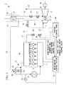
- Fig. 1 shows, in outline, the configuration of an exhaust-heat recovery system according to the embodiment of the present invention.
- a ship-propulsion diesel engine 3 is used as a main engine.
- An exhaust-heat recovery system 1 includes the ship-propulsion diesel engine (main engine) 3, an exhaust turbocharger 5 that is driven by exhaust gas from the diesel engine 3, a power turbine (gas turbine) 7 that is driven by exhaust gas from the diesel engine 3, the exhaust gas being extracted from an upstream side of the exhaust turbocharger 5, an exhaust gas economizer (exhaust gas boiler) 11 that generates steam from exhaust gas from the diesel engine 3, and a steam turbine 9 that is driven by the steam generated by the exhaust gas economizer 11.
- the output from the diesel engine 3 is directly or indirectly connected to a screw propeller via a propeller shaft. Furthermore, exhaust ports of cylinder parts 13 of respective cylinders in the diesel engine 3 are connected to an exhaust manifold 15 serving as an exhaust-gas collecting pipe, and the exhaust manifold 15 is connected to an inlet side of a turbine part 5a of the exhaust turbocharger 5 via a first exhaust pipe L1. Furthermore, the exhaust manifold 15 is connected to an inlet side of the power turbine 7 via a second exhaust pipe L2 (extracted-gas pathway), so that part of the exhaust gas is extracted before being supplied to the exhaust turbocharger 5 and is supplied to the power turbine 7.
- air-supply ports of the cylinder parts 13 are connected to an air-supply manifold 17, and the air-supply manifold 17 is connected to a compressor part 5b of the exhaust turbocharger 5 via an air-supply pipe K1. Furthermore, an air cooler (intercooler) 19 is provided on the air-supply pipe K1.
- the exhaust turbocharger 5 is composed of the turbine part 5a, the compressor part 5b, and a rotary shaft 5c that couples the turbine part 5a with the compressor part 5b.
- the power turbine 7 is rotationally driven by exhaust gas extracted from the exhaust manifold 15 via the second exhaust pipe L2. Furthermore, the steam turbine 9 is rotationally driven by being supplied with steam generated by the exhaust gas economizer 11.
- Exhaust gas discharged from an outlet side of the turbine part 5a of the exhaust turbocharger 5 via a third exhaust pipe L3 and exhaust gas discharged from an outlet side of the power turbine 7 via a fourth exhaust pipe L4 are introduced to the exhaust gas economizer 11.
- a heat exchange part 21 in the exhaust gas economizer 11 generates steam by evaporating water supplied via a water supply pipe 23 using the heat of the exhaust gas. Then, steam generated at the exhaust gas economizer 11 is introduced to the steam turbine 9 via a first steam pipe J1, and steam that has been utilized at the steam turbine 9 is discharged via a second steam pipe J2 and is introduced to a condenser (not shown).
- the power turbine 7 and the steam turbine 9 are coupled in series to drive a generator 25.
- a rotary shaft 29 of the steam turbine 9 is connected to the generator 25 via a reducer and a coupling (not shown).
- a rotary shaft 27 of the power turbine 7 is coupled with the rotary shaft 29 of the steam turbine 9 via a reducer (not shown) and a clutch 31.
- a clutch that connects or disconnects the shafts at a predetermined rotating speed is used as the clutch 31, and an SSS (Synchro-Self-Shifting) clutch is preferably used, for example.
- the generator may be connected to each of the power turbine 7 and the steam turbine 9.
- the second exhaust pipe L2 is provided with an exhaust-gas-amount control valve 33 that controls the amount of exhaust gas to be introduced to the power turbine 7 and an emergency-stop emergency shutoff valve 35 that shuts off the supply of exhaust gas to the power turbine 7 in the event of an emergency.
- an exhaust-gas bypass pipe L5 is provided by being branched off from the second exhaust pipe L2 and joins the fourth exhaust pipe L4.
- the exhaust-gas bypass pipe L5 is provided with an exhaust-gas bypass-amount control valve 34.
- a throttle mechanism for example, an orifice 40, is provided at a downstream side of the exhaust-gas bypass-amount control valve 34 so as to control the flow rate of exhaust gas flowing in the exhaust-gas bypass pipe L5.
- the exhaust-gas bypass-amount control valve 34 is controlled such that the scavenging pressure of the diesel engine 3 is kept at a minimum allowable scavenging pressure.
- the minimum allowable scavenging pressure is a minimum scavenging pressure that is set in advance according to the engine load and a scavenging pressure that is required for fuel combustion in the diesel engine 3.
- the exhaust-gas bypass-amount control valve 34 is controlled so as to ensure the minimum allowable scavenging pressure, which is set in advance according to the engine load.
- the exhaust-gas bypass-amount control valve 34 is adjusted so as to be open during reduced-speed operation, thereby increasing the amount of exhaust gas to be discharged to the exhaust gas economizer 11 without passing through the power turbine 7. As a result, it is possible to increase the amount of steam evaporated at the exhaust gas economizer 11, thus accelerating start-up of the steam turbine 9 during low-load operation. Furthermore, it is possible to increase the amount of power generated at the generator 25 during the low-load operation.
- the first steam pipe J1 is provided with a steam-amount control valve 37 that controls the amount of steam to be introduced to the steam turbine 9 and an emergency-stop emergency shutoff valve 39 that shuts off the supply of steam to the steam turbine 9 in the event of an emergency.
- the degree-of-opening of each of the above-described exhaust-gas-amount control valve 33, the exhaust-gas bypass-amount control valve 34, and the steam-amount control valve 37 is controlled by a control device 43.
- the generator 25 is driven by using, as power, exhaust energy of exhaust gas (combustion gas) from the ship-propulsion diesel engine 3 and forms an exhaust energy recovery apparatus.
- exhaust gas combustion gas
- the rotating speed of the power turbine 7 needs to be increased up to the rotating speed of the steam turbine 9. Furthermore, the power turbine 7 needs to take the lowest load during operation. To start outputting power from the power turbine 7, a large amount of exhaust gas is required, and the load of the main engine needs to be somewhat high.
- the exhaust-gas-amount control valve 33 is opened to supply exhaust gas to the power turbine 7, thereby making it possible to start outputting power from the power turbine 7.
- the power turbine 7 is started up.
- the main-engine load for starting up the power turbine 7 is 50%
- the present invention is not limited to this example case and can be applied to a case in which such a main-engine load is lower than 50%, for example, 45%.
- the exhaust-gas-amount control valve 33 is opened, thereby starting the operation of the power turbine 7. Then, as shown in Fig. 3 , in order to maintain a constant output of the power turbine 7 irrespective of the increase in the main-engine load, the amount of exhaust gas that is to be supplied to the power turbine 7 is maintained constant, and the amount of exhaust gas that is not to be supplied to the power turbine 7 is sent to the turbine part 5a of the exhaust turbocharger 5.
- the amount of exhaust gas that is to be supplied to the power turbine 7 may be set to a constant amount to make it easy to control or is adjusted at a predetermined flow rate using a turbine control panel 44 to make it optimal from the viewpoint of overall energy balance.
- exhaust gas that is discharged from the outlet side of the turbine part 5a of the exhaust turbocharger 5 via the third exhaust pipe L3 and exhaust gas that is discharged from the outlet side of the power turbine 7 via the fourth exhaust pipe L4 are introduced to the exhaust gas economizer 11. Then, steam generated at the exhaust gas economizer 11 is introduced to the steam turbine 9 to drive the steam turbine 9.
- an open limit for the exhaust-gas-amount control valve 33 is sent from a main-engine control system 43 to the turbine control panel 44, the exhaust-gas-amount control valve 33 is closed, and the supply of exhaust gas to the power turbine 7 is stopped.
- the output of the power turbine 7 becomes 0 (zero).
- an open request for the exhaust-gas bypass-amount control valve 34 is sent from the turbine control panel 44 to the main-engine control system 43, and the exhaust-gas bypass-amount control valve 34 is opened.
- the degree-of-opening of the exhaust-gas bypass-amount control valve 34 is adjusted by the main-engine control system 43 such that the scavenging pressure of the diesel engine 3 is kept at the minimum allowable scavenging pressure (see Fig. 4 ).
- the main-engine control system 43 and the turbine control panel 44 are example control parts.
- exhaust gas that is discharged from the outlet side of the turbine part 5a of the exhaust turbocharger 5 via the third exhaust pipe L3 and exhaust gas that is discharged via the exhaust-gas bypass pipe L5, on which the exhaust-gas bypass-amount control valve 34 is provided, are introduced to the exhaust gas economizer 11.
- steam generated at the exhaust gas economizer 11 is introduced to the steam turbine 9 to drive the steam turbine 9.
- the main-engine control system 43 starts to open the exhaust-gas bypass-amount control valve 34 such that the scavenging pressure of the diesel engine 3 is kept at the minimum allowable scavenging pressure. Accordingly, it is possible to introduce exhaust gas to the exhaust gas economizer 11 while preventing the scavenging pressure of the diesel engine 3 from becoming lower than the minimum allowable scavenging pressure. As a result, it is possible to drive the steam turbine 9 to generate power even during low-load operation.
- the exhaust-gas bypass-amount control valve 34 is controlled so as to ensure the minimum allowable scavenging pressure, which is set in advance according to the main-engine load. Specifically, it is determined whether there is an allowance for the air pressure at the outlet of the compressor part 5b of the exhaust turbocharger 5. Then, the degree-of-opening of the exhaust-gas bypass-amount control valve 34 is adjusted according to the degree-of-allowance for the air pressure at the outlet of the compressor part 5b.
- valve provided on the exhaust-gas bypass pipe L5 when a valve provided on the exhaust-gas bypass pipe L5 is used during low-load operation, the degree-of-opening thereof is not adjusted, and just switching between opening and closing is performed.
- the valve provided on the exhaust-gas bypass pipe L5 can be opened for the first time when the main-engine load becomes about 35%, for example.
- the degree-of-opening of the exhaust-gas bypass-amount control valve 34 which is provided on the exhaust-gas bypass pipe L5, can be adjusted. Then, the exhaust-gas bypass-amount control valve 34 is controlled such that the scavenging pressure of the diesel engine 3 is kept at the minimum allowable scavenging pressure. Therefore, even when the main-engine load is about 25%, for example, exhaust gas can be discharged to the exhaust gas economizer 11 via the exhaust-gas bypass pipe L5. As a result, it is possible to drive the steam turbine 9 when the main-engine load is lower than in conventional technologies. When the main-engine load is increased from zero or from a state in which it is close to zero, it is possible to accelerate start-up of the steam turbine 9 compared with conventional technologies and to increase the amount of power generated by the steam turbine 9 during low-load operation.
- the exhaust-gas-amount control valve 33 when the main-engine load is equal to or higher than about 50%, for example, the exhaust-gas-amount control valve 33 is open, and the exhaust-gas bypass-amount control valve 34 is closed. Therefore, it is possible to achieve stable utilization of exhaust gas extracted from the diesel engine 3.
- the exhaust-gas bypass pipe L5 may be connected to the third exhaust pipe L3, and exhaust gas that does not pass through the power turbine 7 may be supplied to the exhaust gas economizer 11 via the exhaust-gas bypass pipe L5 and the third exhaust pipe L3.
Landscapes
- Engineering & Computer Science (AREA)
- Chemical & Material Sciences (AREA)
- Combustion & Propulsion (AREA)
- Mechanical Engineering (AREA)
- General Engineering & Computer Science (AREA)
- Engine Equipment That Uses Special Cycles (AREA)
- Control Of Turbines (AREA)
- Supercharger (AREA)
Abstract
Description
- The present invention relates to an exhaust-heat recovery system and an exhaust-heat recovery method.
- An exhaust-heat recovery system is installed in ships in some cases, and the exhaust-heat recovery system includes a main engine, such as a diesel engine, a power turbine (gas turbine), a steam turbine, and an exhaust gas economizer. The power turbine and the steam turbine are driven by using, as a power source, exhaust energy of exhaust gas (combustion gas) discharged from the main engine, and a generator connected to the power turbine and the steam turbine generates power.
-
PTL 1 discloses a technology, for use in an exhaust-heat recovery system, relating to a turbine-generator control method and apparatus that are capable of reducing generation power without wastefully consuming diesel engine fuel when demand power is reduced, and generation power becomes excessive. - {PTL1} Japanese Unexamined Patent Application, Publication No.
2011-27053 - In marine transportation, in order to reduce the fuel consumption, the main engine is not made to perform rated operation but is made to perform reduced-speed operation in which the speed is reduced, for cruising. As a result, the cost of fuel can be significantly reduced.
- On the other hand, an exhaust-heat recovery system generally built into ships is designed such that the main-engine load is 90% in a high-load range, for example. A power turbine uses exhaust gas from a main engine as a driving source, and, when the main-engine load becomes about 50%, for example, the exhaust gas is introduced to the power turbine, thereby making it possible to operate the power turbine.
- However, during cruising with reduced-speed operation, the main engine is operated with the main-engine load being set at 50% or lower. Therefore, the exhaust-gas temperature of exhaust gas discharged from the main engine is low, and thus the amount of steam evaporated at an exhaust gas economizer is also small. Therefore, during reduced-speed operation, in the exhaust-heat recovery system, the power turbine is not driven, and, in addition, the amount of power generated by driving the steam turbine is small, or it becomes impossible to operate the steam turbine, and thus no power is generated.
- The present invention has been made in view of such circumstances, and an object thereof is to provide an exhaust-heat recovery system and an exhaust-heat recovery method that are capable of generating power by finding conditions for allowing the steam turbine and the gas turbine to be driven even when the main engine is operated in a low-load range and capable of recovering exhaust heat.
- In order to solve the above-described problems, the exhaust-heat recovery system and the exhaust-heat recovery method of the present invention employ the following solutions.
- Specifically, according to a first aspect, the present invention provides an exhaust-heat recovery system including: an engine part; a gas turbine that is driven by exhaust gas discharged from the engine part; a heat exchange part that generates steam by performing heat exchange with exhaust gas discharged from the engine part; a steam turbine that is driven by the steam supplied from the heat exchange part; a first flow-rate control valve that adjusts the flow rate of the exhaust gas supplied from the engine part to the heat exchange part via the gas turbine; a second flow-rate control valve that adjusts the flow rate of the exhaust gas supplied from the engine part to the heat exchange part without passing through the gas turbine; and a control part that controls a degree-of-opening of the first flow-rate control valve and a degree-of-opening of the second flow-rate control valve, in which the control part adjusts the degree-of-opening of the second flow-rate control valve according to a scavenging pressure of the engine part and opens or closes the first flow-rate control valve.
- According to this configuration, in a case in which the first flow-rate control valve is closed, and thus there is no exhaust gas to be supplied from the engine part to the heat exchange part via the gas turbine, the degree-of-opening of the second flow-rate control valve is adjusted, thereby supplying exhaust gas from the engine part to the heat exchange part without making it pass through the gas turbine. As a result, even when the gas turbine is not driven, it is possible to generate steam at the heat exchange part and to drive the steam turbine. Then, because the degree-of-opening of the second flow-rate control valve is adjusted according to the scavenging pressure of the engine part, the minimum allowable scavenging pressure of the engine part can also be ensured.
- In the first aspect of the present invention, the control part may adjust the degree-of-opening of the second flow-rate control valve so as to increase the degree-of-opening thereof as the scavenging pressure of the engine part is increased when the first flow-rate control valve is closed and may adjust the degree-of-opening of the second flow-rate control valve so as to reduce the degree-of-opening thereof as the scavenging pressure of the engine part is reduced when first flow-rate control valve is closed.
- In the first aspect of the present invention, the control part may close the first flow-rate control valve, in an engine load range in which a rotating speed of the gas turbine is lower than a rotating speed of the steam turbine, and may adjust the degree-of-opening of the second flow-rate control valve according to the scavenging pressure of the engine part.
- In the first aspect of the present invention, the control part may close the second flow-rate control valve when the first flow-rate control valve is open.
- In the first aspect of the present invention, the control part may open the first flow-rate control valve, in an engine load range in which the rotating speed of the gas turbine is higher than the rotating speed of the steam turbine, and may close the degree-of-opening of the second flow-rate control valve irrespective of the scavenging pressure of the engine part.
- According to a second aspect, the present invention provides an exhaust-heat recovery method including: a step of driving an engine part; a step of driving a gas turbine by using exhaust gas discharged from the engine part; a step of generating steam at a heat exchange part by using exhaust gas discharged from the engine part; a step of driving a steam turbine by using the steam generated at the heat exchange part; a step of adjusting the flow rate of the exhaust gas supplied from the engine part to the heat exchange part via the gas turbine; and a step of adjusting the flow rate of the exhaust gas supplied from the engine part to the heat exchange part without passing through the gas turbine, in which the flow rate of the exhaust gas supplied from the engine part to the heat exchange part is adjusted according to the scavenging pressure of the engine part, without causing the exhaust gas to flow into the gas turbine.
- According to the present invention, it is possible to generate power by finding conditions for allowing the steam turbine and the gas turbine to be driven even when the main engine is operated in a low-load range and to recover exhaust heat.
-
- {
Fig. 1} Fig. 1 is a view showing the configuration of an exhaust-heat recovery system according to one embodiment of the present invention. - {
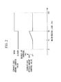
Fig. 2} Fig. 2 is a timing chart showing opening/closing of an exhaust-gas-amount control valve and an exhaust-gas bypass-amount control valve of the exhaust-heat recovery system according to the embodiment of the present invention. - {
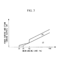
Fig. 3} Fig. 3 is a graph showing the relationship between the outputs of a power turbine and a steam turbine and a main-engine load, in the exhaust-heat recovery system according to the embodiment of the present invention. - {
Fig. 4} Fig. 4 is a graph showing the relationship between the main-engine scavenging pressure and the main-engine load, in the exhaust-heat recovery system according to the embodiment of the present invention. - {
Fig. 5} Fig. 5 is a view showing the configuration of an exhaust-heat recovery system according to the embodiment of the present invention. - An embodiment of the present invention will be described below with reference to the drawings.
-
Fig. 1 shows, in outline, the configuration of an exhaust-heat recovery system according to the embodiment of the present invention. In this embodiment, a ship-propulsion diesel engine 3 is used as a main engine. - An exhaust-
heat recovery system 1 includes the ship-propulsion diesel engine (main engine) 3, anexhaust turbocharger 5 that is driven by exhaust gas from the diesel engine 3, a power turbine (gas turbine) 7 that is driven by exhaust gas from the diesel engine 3, the exhaust gas being extracted from an upstream side of theexhaust turbocharger 5, an exhaust gas economizer (exhaust gas boiler) 11 that generates steam from exhaust gas from the diesel engine 3, and asteam turbine 9 that is driven by the steam generated by theexhaust gas economizer 11. - The output from the diesel engine 3 is directly or indirectly connected to a screw propeller via a propeller shaft. Furthermore, exhaust ports of
cylinder parts 13 of respective cylinders in the diesel engine 3 are connected to anexhaust manifold 15 serving as an exhaust-gas collecting pipe, and theexhaust manifold 15 is connected to an inlet side of aturbine part 5a of theexhaust turbocharger 5 via a first exhaust pipe L1. Furthermore, theexhaust manifold 15 is connected to an inlet side of the power turbine 7 via a second exhaust pipe L2 (extracted-gas pathway), so that part of the exhaust gas is extracted before being supplied to theexhaust turbocharger 5 and is supplied to the power turbine 7. - On the other hand, air-supply ports of the
cylinder parts 13 are connected to an air-supply manifold 17, and the air-supply manifold 17 is connected to acompressor part 5b of theexhaust turbocharger 5 via an air-supply pipe K1. Furthermore, an air cooler (intercooler) 19 is provided on the air-supply pipe K1. - The
exhaust turbocharger 5 is composed of theturbine part 5a, thecompressor part 5b, and arotary shaft 5c that couples theturbine part 5a with thecompressor part 5b. - The power turbine 7 is rotationally driven by exhaust gas extracted from the
exhaust manifold 15 via the second exhaust pipe L2. Furthermore, thesteam turbine 9 is rotationally driven by being supplied with steam generated by theexhaust gas economizer 11. - Exhaust gas discharged from an outlet side of the
turbine part 5a of theexhaust turbocharger 5 via a third exhaust pipe L3 and exhaust gas discharged from an outlet side of the power turbine 7 via a fourth exhaust pipe L4 are introduced to theexhaust gas economizer 11. Aheat exchange part 21 in theexhaust gas economizer 11 generates steam by evaporating water supplied via awater supply pipe 23 using the heat of the exhaust gas. Then, steam generated at the exhaust gas economizer 11 is introduced to thesteam turbine 9 via a first steam pipe J1, and steam that has been utilized at thesteam turbine 9 is discharged via a second steam pipe J2 and is introduced to a condenser (not shown). - The power turbine 7 and the
steam turbine 9 are coupled in series to drive agenerator 25. Arotary shaft 29 of thesteam turbine 9 is connected to thegenerator 25 via a reducer and a coupling (not shown). Furthermore, arotary shaft 27 of the power turbine 7 is coupled with therotary shaft 29 of thesteam turbine 9 via a reducer (not shown) and aclutch 31. A clutch that connects or disconnects the shafts at a predetermined rotating speed is used as theclutch 31, and an SSS (Synchro-Self-Shifting) clutch is preferably used, for example. Note that, instead of coupling the power turbine 7 and thesteam turbine 9 in series, the generator may be connected to each of the power turbine 7 and thesteam turbine 9. - Furthermore, the second exhaust pipe L2 is provided with an exhaust-gas-
amount control valve 33 that controls the amount of exhaust gas to be introduced to the power turbine 7 and an emergency-stopemergency shutoff valve 35 that shuts off the supply of exhaust gas to the power turbine 7 in the event of an emergency. Furthermore, an exhaust-gas bypass pipe L5 is provided by being branched off from the second exhaust pipe L2 and joins the fourth exhaust pipe L4. The exhaust-gas bypass pipe L5 is provided with an exhaust-gas bypass-amount control valve 34. Furthermore, a throttle mechanism, for example, anorifice 40, is provided at a downstream side of the exhaust-gas bypass-amount control valve 34 so as to control the flow rate of exhaust gas flowing in the exhaust-gas bypass pipe L5. The exhaust-gas bypass-amount control valve 34 is controlled such that the scavenging pressure of the diesel engine 3 is kept at a minimum allowable scavenging pressure. Here, the minimum allowable scavenging pressure is a minimum scavenging pressure that is set in advance according to the engine load and a scavenging pressure that is required for fuel combustion in the diesel engine 3. Specifically, while always monitoring the scavenging pressure of the diesel engine 3, the exhaust-gas bypass-amount control valve 34 is controlled so as to ensure the minimum allowable scavenging pressure, which is set in advance according to the engine load. The exhaust-gas bypass-amount control valve 34 is adjusted so as to be open during reduced-speed operation, thereby increasing the amount of exhaust gas to be discharged to theexhaust gas economizer 11 without passing through the power turbine 7. As a result, it is possible to increase the amount of steam evaporated at theexhaust gas economizer 11, thus accelerating start-up of thesteam turbine 9 during low-load operation. Furthermore, it is possible to increase the amount of power generated at thegenerator 25 during the low-load operation. - Furthermore, the first steam pipe J1 is provided with a steam-
amount control valve 37 that controls the amount of steam to be introduced to thesteam turbine 9 and an emergency-stopemergency shutoff valve 39 that shuts off the supply of steam to thesteam turbine 9 in the event of an emergency. The degree-of-opening of each of the above-described exhaust-gas-amount control valve 33, the exhaust-gas bypass-amount control valve 34, and the steam-amount control valve 37 is controlled by acontrol device 43. - As described above, the
generator 25 is driven by using, as power, exhaust energy of exhaust gas (combustion gas) from the ship-propulsion diesel engine 3 and forms an exhaust energy recovery apparatus. - Next, adjustment of the exhaust-gas bypass amount and the operation of the power turbine 7 or the
steam turbine 9 will be described with reference toFigs. 2 and3 . - In order to start up the power turbine 7, the rotating speed of the power turbine 7 needs to be increased up to the rotating speed of the
steam turbine 9. Furthermore, the power turbine 7 needs to take the lowest load during operation. To start outputting power from the power turbine 7, a large amount of exhaust gas is required, and the load of the main engine needs to be somewhat high. - Therefore, in a state where the rotating speed of the power turbine 7 becomes equal to or higher than the rotating speed of the
steam turbine 9, the exhaust-gas-amount control valve 33 is opened to supply exhaust gas to the power turbine 7, thereby making it possible to start outputting power from the power turbine 7. - For example, when an operation in which the main-engine load exceeds 50% is performed, and the rotating speed of the power turbine 7 is increased up to the rotating speed of the
steam turbine 9, the power turbine 7 is started up. Note that, although a description will be given below of a case in which the main-engine load for starting up the power turbine 7 is 50%, the present invention is not limited to this example case and can be applied to a case in which such a main-engine load is lower than 50%, for example, 45%. - When the main-engine load is increased from a state in which it is lower than 50% to reach 50%, the exhaust-gas-
amount control valve 33 is opened, thereby starting the operation of the power turbine 7. Then, as shown inFig. 3 , in order to maintain a constant output of the power turbine 7 irrespective of the increase in the main-engine load, the amount of exhaust gas that is to be supplied to the power turbine 7 is maintained constant, and the amount of exhaust gas that is not to be supplied to the power turbine 7 is sent to theturbine part 5a of theexhaust turbocharger 5. Here, the amount of exhaust gas that is to be supplied to the power turbine 7 may be set to a constant amount to make it easy to control or is adjusted at a predetermined flow rate using aturbine control panel 44 to make it optimal from the viewpoint of overall energy balance. - Note that, in order to achieve stable utilization of main-engine exhaust, when the main-engine load is equal to or higher than 50%, the exhaust-gas bypass-
amount control valve 34 is kept closed. - When the main-engine load is equal to or higher than 50%, exhaust gas that is discharged from the outlet side of the
turbine part 5a of theexhaust turbocharger 5 via the third exhaust pipe L3 and exhaust gas that is discharged from the outlet side of the power turbine 7 via the fourth exhaust pipe L4 are introduced to theexhaust gas economizer 11. Then, steam generated at theexhaust gas economizer 11 is introduced to thesteam turbine 9 to drive thesteam turbine 9. - On the other hand, when the main-engine load is decreased from a state in which it is high to become lower than 50%, an open limit for the exhaust-gas-
amount control valve 33 is sent from a main-engine control system 43 to theturbine control panel 44, the exhaust-gas-amount control valve 33 is closed, and the supply of exhaust gas to the power turbine 7 is stopped. As a result, as shown inFig. 3 , the output of the power turbine 7 becomes 0 (zero). Furthermore, an open request for the exhaust-gas bypass-amount control valve 34 is sent from theturbine control panel 44 to the main-engine control system 43, and the exhaust-gas bypass-amount control valve 34 is opened. - Then, when the main-engine load is lower than 50%, the degree-of-opening of the exhaust-gas bypass-
amount control valve 34 is adjusted by the main-engine control system 43 such that the scavenging pressure of the diesel engine 3 is kept at the minimum allowable scavenging pressure (seeFig. 4 ). Here, the main-engine control system 43 and theturbine control panel 44 are example control parts. - As a result, exhaust gas that is discharged from the outlet side of the
turbine part 5a of theexhaust turbocharger 5 via the third exhaust pipe L3 and exhaust gas that is discharged via the exhaust-gas bypass pipe L5, on which the exhaust-gas bypass-amount control valve 34 is provided, are introduced to theexhaust gas economizer 11. Then, steam generated at theexhaust gas economizer 11 is introduced to thesteam turbine 9 to drive thesteam turbine 9. - Therefore, by opening the exhaust-gas bypass-
amount control valve 34, the amount of steam evaporated at theexhaust gas economizer 11 is increased, thus making it possible to drive thesteam turbine 9 during low-load operation. - For example, when the main-engine load is increased from a state in which it is lower than 25% to become equal to or higher than 25%, the main-
engine control system 43 starts to open the exhaust-gas bypass-amount control valve 34 such that the scavenging pressure of the diesel engine 3 is kept at the minimum allowable scavenging pressure. Accordingly, it is possible to introduce exhaust gas to theexhaust gas economizer 11 while preventing the scavenging pressure of the diesel engine 3 from becoming lower than the minimum allowable scavenging pressure. As a result, it is possible to drive thesteam turbine 9 to generate power even during low-load operation. - When the main-engine load is equal to or higher than 25% and is lower than 50%, while always monitoring the scavenging pressure of the diesel engine 3 during operation, the exhaust-gas bypass-
amount control valve 34 is controlled so as to ensure the minimum allowable scavenging pressure, which is set in advance according to the main-engine load. Specifically, it is determined whether there is an allowance for the air pressure at the outlet of thecompressor part 5b of theexhaust turbocharger 5. Then, the degree-of-opening of the exhaust-gas bypass-amount control valve 34 is adjusted according to the degree-of-allowance for the air pressure at the outlet of thecompressor part 5b. - On the other hand, when the main-engine load is decreased from a state in which it is higher than 25% to become lower than 25%, the exhaust-gas bypass-
amount control valve 34 is closed. As a result, the scavenging pressure of the diesel engine 3 is kept higher than the minimum allowable scavenging pressure. - In conventional technologies, when a valve provided on the exhaust-gas bypass pipe L5 is used during low-load operation, the degree-of-opening thereof is not adjusted, and just switching between opening and closing is performed. For example, in order to ensure the minimum allowable scavenging pressure at the diesel engine 3, the valve provided on the exhaust-gas bypass pipe L5 can be opened for the first time when the main-engine load becomes about 35%, for example.
- On the other hand, in this embodiment, the degree-of-opening of the exhaust-gas bypass-
amount control valve 34, which is provided on the exhaust-gas bypass pipe L5, can be adjusted. Then, the exhaust-gas bypass-amount control valve 34 is controlled such that the scavenging pressure of the diesel engine 3 is kept at the minimum allowable scavenging pressure. Therefore, even when the main-engine load is about 25%, for example, exhaust gas can be discharged to theexhaust gas economizer 11 via the exhaust-gas bypass pipe L5. As a result, it is possible to drive thesteam turbine 9 when the main-engine load is lower than in conventional technologies. When the main-engine load is increased from zero or from a state in which it is close to zero, it is possible to accelerate start-up of thesteam turbine 9 compared with conventional technologies and to increase the amount of power generated by thesteam turbine 9 during low-load operation. - As described above, according to this embodiment, it is possible to introduce high-temperature exhaust gas extracted from the
exhaust manifold 15 to theexhaust gas economizer 11, whereas it is impossible, with conventional technologies, to drive thesteam turbine 9 to generate power in thegenerator 25 because the temperature of exhaust gas is low during reduced-speed sailing. Then, because the amount of exhaust gas extracted from theexhaust manifold 15 is controlled by the exhaust-gas bypass-amount control valve 34, the scavenging pressure of the diesel engine 3 can be kept higher than the minimum allowable scavenging pressure. Furthermore, because the amount of steam evaporated at theexhaust gas economizer 11 can be significantly increased during reduced-speed sailing compared with conventional technologies, the power generating capacity of thesteam turbine 9 can be enhanced even during reduced-speed operation. - Furthermore, in this embodiment, when the main-engine load is equal to or higher than about 50%, for example, the exhaust-gas-
amount control valve 33 is open, and the exhaust-gas bypass-amount control valve 34 is closed. Therefore, it is possible to achieve stable utilization of exhaust gas extracted from the diesel engine 3. - Note that, although a description has been given of the example case shown in
Fig. 1 in which the exhaust-gas bypass pipe L5 is connected to the fourth exhaust pipe L4, the present invention is not limited to this example case. For example, as shown inFig. 5 , the exhaust-gas bypass pipe L5 may be connected to the third exhaust pipe L3, and exhaust gas that does not pass through the power turbine 7 may be supplied to theexhaust gas economizer 11 via the exhaust-gas bypass pipe L5 and the third exhaust pipe L3. -
- 1
- exhaust-heat recovery system
- 3
- diesel engine (engine part)
- 7
- power turbine (gas turbine)
- 9
- steam turbine
- 11
- exhaust gas economizer (heat exchange part)
- 25
- generator
- 33
- exhaust-gas-amount control valve (first flow-rate control valve)
- 34
- exhaust-gas bypass-amount control valve (second flow-rate control valve)
- 43
- main-engine control system (control part)
- 44
- turbine control panel (control part)
Claims (6)
- An exhaust-heat recovery system comprising:an engine part;a gas turbine that is driven by exhaust gas discharged from the engine part;a heat exchange part that generates steam by performing heat exchange with exhaust gas discharged from the engine part;a steam turbine that is driven by the steam supplied from the heat exchange part;a first flow-rate control valve that adjusts the flow rate of the exhaust gas supplied from the engine part to the heat exchange part via the gas turbine;a second flow-rate control valve that adjusts the flow rate of the exhaust gas supplied from the engine part to the heat exchange part without passing through the gas turbine; anda control part that controls a degree-of-opening of the first flow-rate control valve and a degree-of-opening of the second flow-rate control valve,wherein the control part adjusts the degree-of-opening of the second flow-rate control valve according to a scavenging pressure of the engine part and opens or closes the first flow-rate control valve.
- An exhaust-heat recovery system according to claim 1, wherein the control part adjusts the degree-of-opening of the second flow-rate control valve so as to increase the degree-of-opening thereof as the scavenging pressure of the engine part is increased when the first flow-rate control valve is closed and adjusts the degree-of-opening of the second flow-rate control valve so as to reduce the degree-of-opening thereof as the scavenging pressure of the engine part is reduced when the first flow-rate control valve is closed.
- An exhaust-heat recovery system according to claim 1 or 2, wherein the control part closes the first flow-rate control valve, in an engine load range in which a rotating speed of the gas turbine is lower than a rotating speed of the steam turbine, and adjusts the degree-of-opening of the second flow-rate control valve according to the scavenging pressure of the engine part.
- An exhaust-heat recovery system according to one of claims 1 to 3, wherein the control part closes the second flow-rate control valve when the first flow-rate control valve is open.
- An exhaust-heat recovery system according to one of claims 1 to 4, wherein the control part opens the first flow-rate control valve, in an engine load range in which the rotating speed of the gas turbine is higher than the rotating speed of the steam turbine, and closes the degree-of-opening of the second flow-rate control valve irrespective of the scavenging pressure of the engine part.
- An exhaust-heat recovery method comprising:a step of driving an engine part;a step of driving a gas turbine by using exhaust gas discharged from the engine part;a step of generating steam at a heat exchange part by using exhaust gas discharged from the engine part;a step of driving a steam turbine by using the steam generated at the heat exchange part;a step of adjusting the flow rate of the exhaust gas supplied from the engine part to the heat exchange part via the gas turbine; anda step of adjusting the flow rate of the exhaust gas supplied from the engine part to the heat exchange part without passing through the gas turbine,wherein the flow rate of the exhaust gas supplied from the engine part to the heat exchange part is adjusted according to the scavenging pressure of the engine part, without causing the exhaust gas to flow into the gas turbine.
Applications Claiming Priority (2)
| Application Number | Priority Date | Filing Date | Title |
|---|---|---|---|
| JP2012273877A JP5563052B2 (en) | 2012-12-14 | 2012-12-14 | Waste heat recovery system and waste heat recovery method |
| PCT/JP2013/069118 WO2014091786A1 (en) | 2012-12-14 | 2013-07-12 | Exhaust heat recovery system and exhaust heat recovery method |
Publications (3)
| Publication Number | Publication Date |
|---|---|
| EP2921659A1 true EP2921659A1 (en) | 2015-09-23 |
| EP2921659A4 EP2921659A4 (en) | 2015-12-23 |
| EP2921659B1 EP2921659B1 (en) | 2017-03-29 |
Family
ID=50934089
Family Applications (1)
| Application Number | Title | Priority Date | Filing Date |
|---|---|---|---|
| EP13862912.6A Not-in-force EP2921659B1 (en) | 2012-12-14 | 2013-07-12 | Exhaust-heat recovery system and exhaust-heat recovery method |
Country Status (5)
| Country | Link |
|---|---|
| EP (1) | EP2921659B1 (en) |
| JP (1) | JP5563052B2 (en) |
| KR (1) | KR101692173B1 (en) |
| CN (1) | CN104838094B (en) |
| WO (1) | WO2014091786A1 (en) |
Families Citing this family (5)
| Publication number | Priority date | Publication date | Assignee | Title |
|---|---|---|---|---|
| JP6869780B2 (en) * | 2017-03-31 | 2021-05-12 | 三菱重工業株式会社 | How to operate a waste treatment plant and a waste treatment plant |
| CN107387217A (en) * | 2017-07-31 | 2017-11-24 | 中国船舶重工集团公司第七研究所 | Power turbine TRT |
| CN111570089B (en) * | 2019-02-19 | 2025-02-11 | 上海必修福企业管理有限公司 | Tail heat power generation device and method |
| JP7178159B2 (en) * | 2019-02-21 | 2022-11-25 | ジャパンマリンユナイテッド株式会社 | Energy recovery device control method |
| CN114876630A (en) * | 2022-01-25 | 2022-08-09 | 侯杰 | Turbo charger of cold pressure boost in high efficiency |
Family Cites Families (8)
| Publication number | Priority date | Publication date | Assignee | Title |
|---|---|---|---|---|
| JPS62607A (en) * | 1985-06-27 | 1987-01-06 | Mitsubishi Heavy Ind Ltd | Power generation plant |
| JPH062607A (en) * | 1992-06-17 | 1994-01-11 | Nippondenso Co Ltd | Detecting device for engine knocking |
| JP5249866B2 (en) * | 2009-06-25 | 2013-07-31 | 三菱重工業株式会社 | Engine exhaust energy recovery device |
| JP5138643B2 (en) | 2009-07-28 | 2013-02-06 | 三菱重工業株式会社 | Turbine generator, turbine generator control method, control device, and ship equipped with the turbine generator |
| JP5155977B2 (en) * | 2009-09-30 | 2013-03-06 | 三菱重工業株式会社 | Power generation system control device, power generation system, and power generation system control method |
| JP5155980B2 (en) * | 2009-10-23 | 2013-03-06 | 三菱重工業株式会社 | Turbo compound system and operation method thereof |
| JP2011148399A (en) * | 2010-01-21 | 2011-08-04 | Mitsubishi Heavy Ind Ltd | Ship and method for operating ship |
| JP2012047094A (en) * | 2010-08-26 | 2012-03-08 | Mitsubishi Heavy Ind Ltd | Marine denitration system and marine vessel comprising the same, and control method for marine denitration system |
-
2012
- 2012-12-14 JP JP2012273877A patent/JP5563052B2/en not_active Expired - Fee Related
-
2013
- 2013-07-12 EP EP13862912.6A patent/EP2921659B1/en not_active Not-in-force
- 2013-07-12 KR KR1020157012442A patent/KR101692173B1/en active Active
- 2013-07-12 WO PCT/JP2013/069118 patent/WO2014091786A1/en not_active Ceased
- 2013-07-12 CN CN201380058282.4A patent/CN104838094B/en active Active
Also Published As
| Publication number | Publication date |
|---|---|
| EP2921659A4 (en) | 2015-12-23 |
| JP2014118864A (en) | 2014-06-30 |
| KR20150065895A (en) | 2015-06-15 |
| CN104838094B (en) | 2016-09-14 |
| JP5563052B2 (en) | 2014-07-30 |
| EP2921659B1 (en) | 2017-03-29 |
| KR101692173B1 (en) | 2017-01-02 |
| WO2014091786A1 (en) | 2014-06-19 |
| CN104838094A (en) | 2015-08-12 |
Similar Documents
| Publication | Publication Date | Title |
|---|---|---|
| EP2492458B1 (en) | Turbo compound system and method for operating same | |
| CN103026037B (en) | engine exhaust energy recovery device | |
| EP2484873B1 (en) | Control device for power generation system, power generation system, and control method for power generation system | |
| EP2610455A1 (en) | Marine vessil denitration system, marine vessel equipped with same, and control method for marine vessel denitration system | |
| EP2921659B1 (en) | Exhaust-heat recovery system and exhaust-heat recovery method | |
| CN102959185B (en) | Turbine generator control method and device | |
| JP2012097716A5 (en) | ||
| JP5138643B2 (en) | Turbine generator, turbine generator control method, control device, and ship equipped with the turbine generator | |
| JP2011027053A5 (en) | ||
| CN104487661B (en) | Internal combustion engine system, ship equipped with the internal combustion engine system, and operation method of the internal combustion engine system | |
| JP2782680B2 (en) | Multi-engine equipment for ships | |
| JP2013029111A (en) | Power generation method, turbine power generator, method of controlling turbine power generator, control device, and ship including the turbine power generator | |
| KR101589424B1 (en) | Power generation system and method for controlling power generation system | |
| JP2016130474A (en) | Supercharging system and method for operating supercharging system | |
| EP3263864B1 (en) | Engine start-up device, start-up method, and ship equipped with start-up device | |
| GB2463641A (en) | Making use of the waste heat from an internal combustion engine | |
| JP5675932B2 (en) | Power generation method, turbine generator, turbine generator control method, control apparatus, and ship equipped with the turbine generator | |
| KR20140124517A (en) | Complement system for performance of turbo charger |
Legal Events
| Date | Code | Title | Description |
|---|---|---|---|
| PUAI | Public reference made under article 153(3) epc to a published international application that has entered the european phase |
Free format text: ORIGINAL CODE: 0009012 |
|
| 17P | Request for examination filed |
Effective date: 20150519 |
|
| AK | Designated contracting states |
Kind code of ref document: A1 Designated state(s): AL AT BE BG CH CY CZ DE DK EE ES FI FR GB GR HR HU IE IS IT LI LT LU LV MC MK MT NL NO PL PT RO RS SE SI SK SM TR |
|
| AX | Request for extension of the european patent |
Extension state: BA ME |
|
| RA4 | Supplementary search report drawn up and despatched (corrected) |
Effective date: 20151119 |
|
| RIC1 | Information provided on ipc code assigned before grant |
Ipc: F02G 5/02 20060101ALI20151113BHEP Ipc: F01N 5/02 20060101ALI20151113BHEP Ipc: F01N 5/04 20060101ALI20151113BHEP Ipc: F01K 23/06 20060101ALI20151113BHEP Ipc: F02B 41/10 20060101ALI20151113BHEP Ipc: F01K 23/10 20060101AFI20151113BHEP |
|
| DAX | Request for extension of the european patent (deleted) | ||
| GRAP | Despatch of communication of intention to grant a patent |
Free format text: ORIGINAL CODE: EPIDOSNIGR1 |
|
| RIC1 | Information provided on ipc code assigned before grant |
Ipc: F01K 23/10 20060101AFI20160920BHEP Ipc: F02G 5/02 20060101ALI20160920BHEP Ipc: F01N 5/02 20060101ALI20160920BHEP Ipc: F01K 23/06 20060101ALI20160920BHEP Ipc: F01N 5/04 20060101ALI20160920BHEP Ipc: F02B 41/10 20060101ALI20160920BHEP |
|
| INTG | Intention to grant announced |
Effective date: 20161007 |
|
| GRAS | Grant fee paid |
Free format text: ORIGINAL CODE: EPIDOSNIGR3 |
|
| GRAJ | Information related to disapproval of communication of intention to grant by the applicant or resumption of examination proceedings by the epo deleted |
Free format text: ORIGINAL CODE: EPIDOSDIGR1 |
|
| GRAL | Information related to payment of fee for publishing/printing deleted |
Free format text: ORIGINAL CODE: EPIDOSDIGR3 |
|
| GRAR | Information related to intention to grant a patent recorded |
Free format text: ORIGINAL CODE: EPIDOSNIGR71 |
|
| INTC | Intention to grant announced (deleted) | ||
| GRAA | (expected) grant |
Free format text: ORIGINAL CODE: 0009210 |
|
| INTG | Intention to grant announced |
Effective date: 20170209 |
|
| AK | Designated contracting states |
Kind code of ref document: B1 Designated state(s): AL AT BE BG CH CY CZ DE DK EE ES FI FR GB GR HR HU IE IS IT LI LT LU LV MC MK MT NL NO PL PT RO RS SE SI SK SM TR |
|
| REG | Reference to a national code |
Ref country code: GB Ref legal event code: FG4D |
|
| REG | Reference to a national code |
Ref country code: CH Ref legal event code: EP |
|
| REG | Reference to a national code |
Ref country code: AT Ref legal event code: REF Ref document number: 879980 Country of ref document: AT Kind code of ref document: T Effective date: 20170415 |
|
| REG | Reference to a national code |
Ref country code: IE Ref legal event code: FG4D |
|
| REG | Reference to a national code |
Ref country code: DE Ref legal event code: R096 Ref document number: 602013019300 Country of ref document: DE |
|
| REG | Reference to a national code |
Ref country code: FR Ref legal event code: PLFP Year of fee payment: 5 |
|
| PG25 | Lapsed in a contracting state [announced via postgrant information from national office to epo] |
Ref country code: GR Free format text: LAPSE BECAUSE OF FAILURE TO SUBMIT A TRANSLATION OF THE DESCRIPTION OR TO PAY THE FEE WITHIN THE PRESCRIBED TIME-LIMIT Effective date: 20170630 Ref country code: HR Free format text: LAPSE BECAUSE OF FAILURE TO SUBMIT A TRANSLATION OF THE DESCRIPTION OR TO PAY THE FEE WITHIN THE PRESCRIBED TIME-LIMIT Effective date: 20170329 Ref country code: FI Free format text: LAPSE BECAUSE OF FAILURE TO SUBMIT A TRANSLATION OF THE DESCRIPTION OR TO PAY THE FEE WITHIN THE PRESCRIBED TIME-LIMIT Effective date: 20170329 Ref country code: LT Free format text: LAPSE BECAUSE OF FAILURE TO SUBMIT A TRANSLATION OF THE DESCRIPTION OR TO PAY THE FEE WITHIN THE PRESCRIBED TIME-LIMIT Effective date: 20170329 Ref country code: NO Free format text: LAPSE BECAUSE OF FAILURE TO SUBMIT A TRANSLATION OF THE DESCRIPTION OR TO PAY THE FEE WITHIN THE PRESCRIBED TIME-LIMIT Effective date: 20170629 |
|
| REG | Reference to a national code |
Ref country code: NL Ref legal event code: MP Effective date: 20170329 |
|
| REG | Reference to a national code |
Ref country code: AT Ref legal event code: MK05 Ref document number: 879980 Country of ref document: AT Kind code of ref document: T Effective date: 20170329 |
|
| PG25 | Lapsed in a contracting state [announced via postgrant information from national office to epo] |
Ref country code: LV Free format text: LAPSE BECAUSE OF FAILURE TO SUBMIT A TRANSLATION OF THE DESCRIPTION OR TO PAY THE FEE WITHIN THE PRESCRIBED TIME-LIMIT Effective date: 20170329 Ref country code: SE Free format text: LAPSE BECAUSE OF FAILURE TO SUBMIT A TRANSLATION OF THE DESCRIPTION OR TO PAY THE FEE WITHIN THE PRESCRIBED TIME-LIMIT Effective date: 20170329 Ref country code: BG Free format text: LAPSE BECAUSE OF FAILURE TO SUBMIT A TRANSLATION OF THE DESCRIPTION OR TO PAY THE FEE WITHIN THE PRESCRIBED TIME-LIMIT Effective date: 20170629 Ref country code: RS Free format text: LAPSE BECAUSE OF FAILURE TO SUBMIT A TRANSLATION OF THE DESCRIPTION OR TO PAY THE FEE WITHIN THE PRESCRIBED TIME-LIMIT Effective date: 20170329 |
|
| PG25 | Lapsed in a contracting state [announced via postgrant information from national office to epo] |
Ref country code: NL Free format text: LAPSE BECAUSE OF FAILURE TO SUBMIT A TRANSLATION OF THE DESCRIPTION OR TO PAY THE FEE WITHIN THE PRESCRIBED TIME-LIMIT Effective date: 20170329 |
|
| PG25 | Lapsed in a contracting state [announced via postgrant information from national office to epo] |
Ref country code: SK Free format text: LAPSE BECAUSE OF FAILURE TO SUBMIT A TRANSLATION OF THE DESCRIPTION OR TO PAY THE FEE WITHIN THE PRESCRIBED TIME-LIMIT Effective date: 20170329 Ref country code: IT Free format text: LAPSE BECAUSE OF FAILURE TO SUBMIT A TRANSLATION OF THE DESCRIPTION OR TO PAY THE FEE WITHIN THE PRESCRIBED TIME-LIMIT Effective date: 20170329 Ref country code: RO Free format text: LAPSE BECAUSE OF FAILURE TO SUBMIT A TRANSLATION OF THE DESCRIPTION OR TO PAY THE FEE WITHIN THE PRESCRIBED TIME-LIMIT Effective date: 20170329 Ref country code: CZ Free format text: LAPSE BECAUSE OF FAILURE TO SUBMIT A TRANSLATION OF THE DESCRIPTION OR TO PAY THE FEE WITHIN THE PRESCRIBED TIME-LIMIT Effective date: 20170329 Ref country code: AT Free format text: LAPSE BECAUSE OF FAILURE TO SUBMIT A TRANSLATION OF THE DESCRIPTION OR TO PAY THE FEE WITHIN THE PRESCRIBED TIME-LIMIT Effective date: 20170329 Ref country code: ES Free format text: LAPSE BECAUSE OF FAILURE TO SUBMIT A TRANSLATION OF THE DESCRIPTION OR TO PAY THE FEE WITHIN THE PRESCRIBED TIME-LIMIT Effective date: 20170329 Ref country code: EE Free format text: LAPSE BECAUSE OF FAILURE TO SUBMIT A TRANSLATION OF THE DESCRIPTION OR TO PAY THE FEE WITHIN THE PRESCRIBED TIME-LIMIT Effective date: 20170329 |
|
| PG25 | Lapsed in a contracting state [announced via postgrant information from national office to epo] |
Ref country code: PL Free format text: LAPSE BECAUSE OF FAILURE TO SUBMIT A TRANSLATION OF THE DESCRIPTION OR TO PAY THE FEE WITHIN THE PRESCRIBED TIME-LIMIT Effective date: 20170329 Ref country code: SM Free format text: LAPSE BECAUSE OF FAILURE TO SUBMIT A TRANSLATION OF THE DESCRIPTION OR TO PAY THE FEE WITHIN THE PRESCRIBED TIME-LIMIT Effective date: 20170329 Ref country code: IS Free format text: LAPSE BECAUSE OF FAILURE TO SUBMIT A TRANSLATION OF THE DESCRIPTION OR TO PAY THE FEE WITHIN THE PRESCRIBED TIME-LIMIT Effective date: 20170729 |
|
| REG | Reference to a national code |
Ref country code: DE Ref legal event code: R097 Ref document number: 602013019300 Country of ref document: DE |
|
| PG25 | Lapsed in a contracting state [announced via postgrant information from national office to epo] |
Ref country code: DK Free format text: LAPSE BECAUSE OF FAILURE TO SUBMIT A TRANSLATION OF THE DESCRIPTION OR TO PAY THE FEE WITHIN THE PRESCRIBED TIME-LIMIT Effective date: 20170329 |
|
| PLBE | No opposition filed within time limit |
Free format text: ORIGINAL CODE: 0009261 |
|
| STAA | Information on the status of an ep patent application or granted ep patent |
Free format text: STATUS: NO OPPOSITION FILED WITHIN TIME LIMIT |
|
| REG | Reference to a national code |
Ref country code: CH Ref legal event code: PL |
|
| 26N | No opposition filed |
Effective date: 20180103 |
|
| GBPC | Gb: european patent ceased through non-payment of renewal fee |
Effective date: 20170712 |
|
| REG | Reference to a national code |
Ref country code: IE Ref legal event code: MM4A |
|
| PG25 | Lapsed in a contracting state [announced via postgrant information from national office to epo] |
Ref country code: IE Free format text: LAPSE BECAUSE OF NON-PAYMENT OF DUE FEES Effective date: 20170712 Ref country code: CH Free format text: LAPSE BECAUSE OF NON-PAYMENT OF DUE FEES Effective date: 20170731 Ref country code: GB Free format text: LAPSE BECAUSE OF NON-PAYMENT OF DUE FEES Effective date: 20170712 Ref country code: LI Free format text: LAPSE BECAUSE OF NON-PAYMENT OF DUE FEES Effective date: 20170731 |
|
| PG25 | Lapsed in a contracting state [announced via postgrant information from national office to epo] |
Ref country code: SI Free format text: LAPSE BECAUSE OF FAILURE TO SUBMIT A TRANSLATION OF THE DESCRIPTION OR TO PAY THE FEE WITHIN THE PRESCRIBED TIME-LIMIT Effective date: 20170329 |
|
| REG | Reference to a national code |
Ref country code: BE Ref legal event code: MM Effective date: 20170731 |
|
| REG | Reference to a national code |
Ref country code: FR Ref legal event code: PLFP Year of fee payment: 6 |
|
| PG25 | Lapsed in a contracting state [announced via postgrant information from national office to epo] |
Ref country code: LU Free format text: LAPSE BECAUSE OF NON-PAYMENT OF DUE FEES Effective date: 20170712 |
|
| PG25 | Lapsed in a contracting state [announced via postgrant information from national office to epo] |
Ref country code: BE Free format text: LAPSE BECAUSE OF NON-PAYMENT OF DUE FEES Effective date: 20170731 |
|
| PG25 | Lapsed in a contracting state [announced via postgrant information from national office to epo] |
Ref country code: MT Free format text: LAPSE BECAUSE OF NON-PAYMENT OF DUE FEES Effective date: 20170712 |
|
| PG25 | Lapsed in a contracting state [announced via postgrant information from national office to epo] |
Ref country code: MC Free format text: LAPSE BECAUSE OF FAILURE TO SUBMIT A TRANSLATION OF THE DESCRIPTION OR TO PAY THE FEE WITHIN THE PRESCRIBED TIME-LIMIT Effective date: 20170329 Ref country code: HU Free format text: LAPSE BECAUSE OF FAILURE TO SUBMIT A TRANSLATION OF THE DESCRIPTION OR TO PAY THE FEE WITHIN THE PRESCRIBED TIME-LIMIT; INVALID AB INITIO Effective date: 20130712 |
|
| PG25 | Lapsed in a contracting state [announced via postgrant information from national office to epo] |
Ref country code: CY Free format text: LAPSE BECAUSE OF FAILURE TO SUBMIT A TRANSLATION OF THE DESCRIPTION OR TO PAY THE FEE WITHIN THE PRESCRIBED TIME-LIMIT Effective date: 20170329 |
|
| PG25 | Lapsed in a contracting state [announced via postgrant information from national office to epo] |
Ref country code: MK Free format text: LAPSE BECAUSE OF FAILURE TO SUBMIT A TRANSLATION OF THE DESCRIPTION OR TO PAY THE FEE WITHIN THE PRESCRIBED TIME-LIMIT Effective date: 20170329 |
|
| PG25 | Lapsed in a contracting state [announced via postgrant information from national office to epo] |
Ref country code: TR Free format text: LAPSE BECAUSE OF FAILURE TO SUBMIT A TRANSLATION OF THE DESCRIPTION OR TO PAY THE FEE WITHIN THE PRESCRIBED TIME-LIMIT Effective date: 20170329 |
|
| PG25 | Lapsed in a contracting state [announced via postgrant information from national office to epo] |
Ref country code: PT Free format text: LAPSE BECAUSE OF FAILURE TO SUBMIT A TRANSLATION OF THE DESCRIPTION OR TO PAY THE FEE WITHIN THE PRESCRIBED TIME-LIMIT Effective date: 20170329 |
|
| PG25 | Lapsed in a contracting state [announced via postgrant information from national office to epo] |
Ref country code: AL Free format text: LAPSE BECAUSE OF FAILURE TO SUBMIT A TRANSLATION OF THE DESCRIPTION OR TO PAY THE FEE WITHIN THE PRESCRIBED TIME-LIMIT Effective date: 20170329 |
|
| PGFP | Annual fee paid to national office [announced via postgrant information from national office to epo] |
Ref country code: FR Payment date: 20240611 Year of fee payment: 12 |
|
| PGFP | Annual fee paid to national office [announced via postgrant information from national office to epo] |
Ref country code: DE Payment date: 20240529 Year of fee payment: 12 |
|
| REG | Reference to a national code |
Ref country code: DE Ref legal event code: R119 Ref document number: 602013019300 Country of ref document: DE |
|
| PG25 | Lapsed in a contracting state [announced via postgrant information from national office to epo] |
Ref country code: DE Free format text: LAPSE BECAUSE OF NON-PAYMENT OF DUE FEES Effective date: 20260203 |
|
| PG25 | Lapsed in a contracting state [announced via postgrant information from national office to epo] |
Ref country code: FR Free format text: LAPSE BECAUSE OF NON-PAYMENT OF DUE FEES Effective date: 20250731 |