EP2921532A1 - Pigment for ink-jet recording, pigment ink for ink-jet recording, and method for producing pigment for ink-jet recording - Google Patents
Pigment for ink-jet recording, pigment ink for ink-jet recording, and method for producing pigment for ink-jet recording Download PDFInfo
- Publication number
- EP2921532A1 EP2921532A1 EP15156905.0A EP15156905A EP2921532A1 EP 2921532 A1 EP2921532 A1 EP 2921532A1 EP 15156905 A EP15156905 A EP 15156905A EP 2921532 A1 EP2921532 A1 EP 2921532A1
- Authority
- EP
- European Patent Office
- Prior art keywords
- ink
- pigment
- jet recording
- porous
- particle
- Prior art date
- Legal status (The legal status is an assumption and is not a legal conclusion. Google has not performed a legal analysis and makes no representation as to the accuracy of the status listed.)
- Granted
Links
Images



Classifications
-
- C—CHEMISTRY; METALLURGY
- C09—DYES; PAINTS; POLISHES; NATURAL RESINS; ADHESIVES; COMPOSITIONS NOT OTHERWISE PROVIDED FOR; APPLICATIONS OF MATERIALS NOT OTHERWISE PROVIDED FOR
- C09D—COATING COMPOSITIONS, e.g. PAINTS, VARNISHES OR LACQUERS; FILLING PASTES; CHEMICAL PAINT OR INK REMOVERS; INKS; CORRECTING FLUIDS; WOODSTAINS; PASTES OR SOLIDS FOR COLOURING OR PRINTING; USE OF MATERIALS THEREFOR
- C09D11/00—Inks
- C09D11/30—Inkjet printing inks
- C09D11/32—Inkjet printing inks characterised by colouring agents
-
- C—CHEMISTRY; METALLURGY
- C09—DYES; PAINTS; POLISHES; NATURAL RESINS; ADHESIVES; COMPOSITIONS NOT OTHERWISE PROVIDED FOR; APPLICATIONS OF MATERIALS NOT OTHERWISE PROVIDED FOR
- C09D—COATING COMPOSITIONS, e.g. PAINTS, VARNISHES OR LACQUERS; FILLING PASTES; CHEMICAL PAINT OR INK REMOVERS; INKS; CORRECTING FLUIDS; WOODSTAINS; PASTES OR SOLIDS FOR COLOURING OR PRINTING; USE OF MATERIALS THEREFOR
- C09D11/00—Inks
- C09D11/30—Inkjet printing inks
- C09D11/32—Inkjet printing inks characterised by colouring agents
- C09D11/322—Pigment inks
-
- B—PERFORMING OPERATIONS; TRANSPORTING
- B01—PHYSICAL OR CHEMICAL PROCESSES OR APPARATUS IN GENERAL
- B01J—CHEMICAL OR PHYSICAL PROCESSES, e.g. CATALYSIS OR COLLOID CHEMISTRY; THEIR RELEVANT APPARATUS
- B01J13/00—Colloid chemistry, e.g. the production of colloidal materials or their solutions, not otherwise provided for; Making microcapsules or microballoons
- B01J13/02—Making microcapsules or microballoons
-
- C—CHEMISTRY; METALLURGY
- C08—ORGANIC MACROMOLECULAR COMPOUNDS; THEIR PREPARATION OR CHEMICAL WORKING-UP; COMPOSITIONS BASED THEREON
- C08K—Use of inorganic or non-macromolecular organic substances as compounding ingredients
- C08K9/00—Use of pretreated ingredients
- C08K9/02—Ingredients treated with inorganic substances
-
- C—CHEMISTRY; METALLURGY
- C08—ORGANIC MACROMOLECULAR COMPOUNDS; THEIR PREPARATION OR CHEMICAL WORKING-UP; COMPOSITIONS BASED THEREON
- C08K—Use of inorganic or non-macromolecular organic substances as compounding ingredients
- C08K9/00—Use of pretreated ingredients
- C08K9/04—Ingredients treated with organic substances
- C08K9/06—Ingredients treated with organic substances with silicon-containing compounds
-
- C—CHEMISTRY; METALLURGY
- C09—DYES; PAINTS; POLISHES; NATURAL RESINS; ADHESIVES; COMPOSITIONS NOT OTHERWISE PROVIDED FOR; APPLICATIONS OF MATERIALS NOT OTHERWISE PROVIDED FOR
- C09C—TREATMENT OF INORGANIC MATERIALS, OTHER THAN FIBROUS FILLERS, TO ENHANCE THEIR PIGMENTING OR FILLING PROPERTIES ; PREPARATION OF CARBON BLACK ; PREPARATION OF INORGANIC MATERIALS WHICH ARE NO SINGLE CHEMICAL COMPOUNDS AND WHICH ARE MAINLY USED AS PIGMENTS OR FILLERS
- C09C1/00—Treatment of specific inorganic materials other than fibrous fillers; Preparation of carbon black
- C09C1/28—Compounds of silicon
- C09C1/30—Silicic acid
- C09C1/3045—Treatment with inorganic compounds
- C09C1/3054—Coating
-
- C—CHEMISTRY; METALLURGY
- C09—DYES; PAINTS; POLISHES; NATURAL RESINS; ADHESIVES; COMPOSITIONS NOT OTHERWISE PROVIDED FOR; APPLICATIONS OF MATERIALS NOT OTHERWISE PROVIDED FOR
- C09C—TREATMENT OF INORGANIC MATERIALS, OTHER THAN FIBROUS FILLERS, TO ENHANCE THEIR PIGMENTING OR FILLING PROPERTIES ; PREPARATION OF CARBON BLACK ; PREPARATION OF INORGANIC MATERIALS WHICH ARE NO SINGLE CHEMICAL COMPOUNDS AND WHICH ARE MAINLY USED AS PIGMENTS OR FILLERS
- C09C1/00—Treatment of specific inorganic materials other than fibrous fillers; Preparation of carbon black
- C09C1/28—Compounds of silicon
- C09C1/30—Silicic acid
- C09C1/309—Combinations of treatments provided for in groups C09C1/3009 - C09C1/3081
-
- C—CHEMISTRY; METALLURGY
- C09—DYES; PAINTS; POLISHES; NATURAL RESINS; ADHESIVES; COMPOSITIONS NOT OTHERWISE PROVIDED FOR; APPLICATIONS OF MATERIALS NOT OTHERWISE PROVIDED FOR
- C09C—TREATMENT OF INORGANIC MATERIALS, OTHER THAN FIBROUS FILLERS, TO ENHANCE THEIR PIGMENTING OR FILLING PROPERTIES ; PREPARATION OF CARBON BLACK ; PREPARATION OF INORGANIC MATERIALS WHICH ARE NO SINGLE CHEMICAL COMPOUNDS AND WHICH ARE MAINLY USED AS PIGMENTS OR FILLERS
- C09C1/00—Treatment of specific inorganic materials other than fibrous fillers; Preparation of carbon black
- C09C1/40—Compounds of aluminium
- C09C1/405—Compounds of aluminium containing combined silica, e.g. mica
-
- C—CHEMISTRY; METALLURGY
- C09—DYES; PAINTS; POLISHES; NATURAL RESINS; ADHESIVES; COMPOSITIONS NOT OTHERWISE PROVIDED FOR; APPLICATIONS OF MATERIALS NOT OTHERWISE PROVIDED FOR
- C09C—TREATMENT OF INORGANIC MATERIALS, OTHER THAN FIBROUS FILLERS, TO ENHANCE THEIR PIGMENTING OR FILLING PROPERTIES ; PREPARATION OF CARBON BLACK ; PREPARATION OF INORGANIC MATERIALS WHICH ARE NO SINGLE CHEMICAL COMPOUNDS AND WHICH ARE MAINLY USED AS PIGMENTS OR FILLERS
- C09C1/00—Treatment of specific inorganic materials other than fibrous fillers; Preparation of carbon black
- C09C1/40—Compounds of aluminium
- C09C1/407—Aluminium oxides or hydroxides
-
- C—CHEMISTRY; METALLURGY
- C09—DYES; PAINTS; POLISHES; NATURAL RESINS; ADHESIVES; COMPOSITIONS NOT OTHERWISE PROVIDED FOR; APPLICATIONS OF MATERIALS NOT OTHERWISE PROVIDED FOR
- C09C—TREATMENT OF INORGANIC MATERIALS, OTHER THAN FIBROUS FILLERS, TO ENHANCE THEIR PIGMENTING OR FILLING PROPERTIES ; PREPARATION OF CARBON BLACK ; PREPARATION OF INORGANIC MATERIALS WHICH ARE NO SINGLE CHEMICAL COMPOUNDS AND WHICH ARE MAINLY USED AS PIGMENTS OR FILLERS
- C09C3/00—Treatment in general of inorganic materials, other than fibrous fillers, to enhance their pigmenting or filling properties
- C09C3/06—Treatment with inorganic compounds
- C09C3/063—Coating
-
- C—CHEMISTRY; METALLURGY
- C09—DYES; PAINTS; POLISHES; NATURAL RESINS; ADHESIVES; COMPOSITIONS NOT OTHERWISE PROVIDED FOR; APPLICATIONS OF MATERIALS NOT OTHERWISE PROVIDED FOR
- C09D—COATING COMPOSITIONS, e.g. PAINTS, VARNISHES OR LACQUERS; FILLING PASTES; CHEMICAL PAINT OR INK REMOVERS; INKS; CORRECTING FLUIDS; WOODSTAINS; PASTES OR SOLIDS FOR COLOURING OR PRINTING; USE OF MATERIALS THEREFOR
- C09D17/00—Pigment pastes, e.g. for mixing in paints
-
- D—TEXTILES; PAPER
- D06—TREATMENT OF TEXTILES OR THE LIKE; LAUNDERING; FLEXIBLE MATERIALS NOT OTHERWISE PROVIDED FOR
- D06P—DYEING OR PRINTING TEXTILES; DYEING LEATHER, FURS OR SOLID MACROMOLECULAR SUBSTANCES IN ANY FORM
- D06P1/00—General processes of dyeing or printing textiles, or general processes of dyeing leather, furs, or solid macromolecular substances in any form, classified according to the dyes, pigments, or auxiliary substances employed
- D06P1/0004—General aspects of dyeing
- D06P1/0016—Dye baths containing a dyeing agent in a special form such as for instance in melted or solid form, as a floating film or gel, spray or aerosol, or atomised dyes
-
- D—TEXTILES; PAPER
- D06—TREATMENT OF TEXTILES OR THE LIKE; LAUNDERING; FLEXIBLE MATERIALS NOT OTHERWISE PROVIDED FOR
- D06P—DYEING OR PRINTING TEXTILES; DYEING LEATHER, FURS OR SOLID MACROMOLECULAR SUBSTANCES IN ANY FORM
- D06P1/00—General processes of dyeing or printing textiles, or general processes of dyeing leather, furs, or solid macromolecular substances in any form, classified according to the dyes, pigments, or auxiliary substances employed
- D06P1/44—General processes of dyeing or printing textiles, or general processes of dyeing leather, furs, or solid macromolecular substances in any form, classified according to the dyes, pigments, or auxiliary substances employed using insoluble pigments or auxiliary substances, e.g. binders
-
- D—TEXTILES; PAPER
- D06—TREATMENT OF TEXTILES OR THE LIKE; LAUNDERING; FLEXIBLE MATERIALS NOT OTHERWISE PROVIDED FOR
- D06P—DYEING OR PRINTING TEXTILES; DYEING LEATHER, FURS OR SOLID MACROMOLECULAR SUBSTANCES IN ANY FORM
- D06P5/00—Other features in dyeing or printing textiles, or dyeing leather, furs, or solid macromolecular substances in any form
- D06P5/30—Ink jet printing
-
- C—CHEMISTRY; METALLURGY
- C01—INORGANIC CHEMISTRY
- C01P—INDEXING SCHEME RELATING TO STRUCTURAL AND PHYSICAL ASPECTS OF SOLID INORGANIC COMPOUNDS
- C01P2004/00—Particle morphology
- C01P2004/60—Particles characterised by their size
- C01P2004/64—Nanometer sized, i.e. from 1-100 nanometer
-
- C—CHEMISTRY; METALLURGY
- C01—INORGANIC CHEMISTRY
- C01P—INDEXING SCHEME RELATING TO STRUCTURAL AND PHYSICAL ASPECTS OF SOLID INORGANIC COMPOUNDS
- C01P2004/00—Particle morphology
- C01P2004/80—Particles consisting of a mixture of two or more inorganic phases
- C01P2004/82—Particles consisting of a mixture of two or more inorganic phases two phases having the same anion, e.g. both oxidic phases
- C01P2004/84—Particles consisting of a mixture of two or more inorganic phases two phases having the same anion, e.g. both oxidic phases one phase coated with the other
-
- C—CHEMISTRY; METALLURGY
- C01—INORGANIC CHEMISTRY
- C01P—INDEXING SCHEME RELATING TO STRUCTURAL AND PHYSICAL ASPECTS OF SOLID INORGANIC COMPOUNDS
- C01P2006/00—Physical properties of inorganic compounds
- C01P2006/11—Powder tap density
-
- C—CHEMISTRY; METALLURGY
- C01—INORGANIC CHEMISTRY
- C01P—INDEXING SCHEME RELATING TO STRUCTURAL AND PHYSICAL ASPECTS OF SOLID INORGANIC COMPOUNDS
- C01P2006/00—Physical properties of inorganic compounds
- C01P2006/60—Optical properties, e.g. expressed in CIELAB-values
- C01P2006/62—L* (lightness axis)
Definitions
- an inorganic pigment for use in a pigment ink a multilayer pigment obtained by coating a base material such as titanium oxide or SiO 2 with layers each having a high refractive index such as TiO 2 is known (see JP 2010-507009 A ).
- sedimentation of the above-mentioned inorganic pigment in the pigment ink is generated over time. Therefore, for example, in the case where printing is performed after it has not been performed for a long period of time, the user shakes an ink cartridge to stir the pigment ink before using.
- the pigment for ink-jet recording comprises: a porous particle; a sealing agent; and an inorganic pigment layer comprising an inorganic pigment, the sealing agent is arranged in a pore opening of the porous particle, and the inorganic pigment layer is formed on the surface of the porous particle.
- the pigment for ink-jet recording comprises: a porous particle; and an inorganic pigment layer comprising an inorganic pigment, the inorganic pigment layer is formed on the surface of the porous particle, and the inorganic pigment is not present in a pore opening of the porous particle inside the inorganic pigment layer.
- the sealing agent is arranged in a pore opening of the porous particle, and the porous particle is coated with the inorganic pigment layer.
- the pigment for ink-jet recording becomes a hollow pigment with a low density and is superior in dispersibility in a solvent.
- the inorganic pigment is not substantially present in a pore opening of the porous particle” means that the pigment for ink-jet recording may contain a small amount of the inorganic pigment in the pore opening within the favorable range of the pigment density described below.
- the pigment for ink-jet recording comprises: a porous particle; a sealing agent; and an inorganic pigment layer comprising an inorganic pigment, the sealing agent is arranged in a pore opening of the porous particle, and the inorganic pigment layer is formed on the surface of the porous particle.
- porous particle examples include a porous silicon oxide particle such as porous silica (SiO 2 ) particle, a porous alminosilicate particle such as zeolite, a porous aluminium oxide particle, a porous zirconium oxide particle, and active carbon, and the porous particle is, for example, a porous silica particle.
- a porous silicon oxide particle such as porous silica (SiO 2 ) particle
- a porous alminosilicate particle such as zeolite
- zeolite zeolite
- aluminium oxide particle a porous aluminium oxide particle
- porous zirconium oxide particle a porous zirconium oxide particle
- active carbon examples include a porous silica particle.
- the sealing agent is not particularly limited as long as it is arranged in a pore opening of the porous particle and is, for example, a chemical compound of organic silicon.
- the chemical compound of organic silicon include alkoxysilane such as tetraethoxysilane (TEOS), trialkylmonosilane such as trimethylmonosilane, alkylsilane such as hexamethyldisilane, and fluoroalkylsilane such as a silane coupling agent having a perfluoroalkyl group.
- the inorganic pigment is not particularly limited, and examples thereof include titanium oxide, sulfate of alkali earth metal, carbonate of alkali earth metal, silica (for example, fine-powdered silicic acid, synthesized silicate), calcium silicate, alumina, hydrated alumina, zinc oxide, talc, and clay. Any one of them may be used alone, or two or more of them may be used in combination. Among them, the inorganic pigment is, for example, titanium oxide.
- the method for producing a pigment for ink-jet recording is described below with reference to (a) to (c) in FIG. 1 .
- the method is merely an example and the pigment for ink-jet recording may be produced by another method.
- a sealing agent 4 is arranged on the entire surface including the outer peripheral surface 2 of a porous particle 1 and the inner surface 3a of a pore opening 3.
- porous particle 1 a commercially available porous particle or a self-prepared porous particle may be used.
- the porous silica particle may be prepared by causing the inside and the surface of an aggregate of ultrafine powder such as as calcium carbonate or the like as a base particle (core) to be immersed in and coated with silica, then dissolving the ultrafine powder in acid, and thereafter drying the ultrafine powder, for example.
- the arrangement of the sealing agent 4 may be performed by a reflux method or a supercritical method using an autoclave, for example.
- the inorganic pigment layer 5 comprising an inorganic pigment is formed on the surface of the porous particle 1.
- the inorganic pigment layer 5 may be formed by stirring a solution containing the porous particle 1 and the inorganic pigment with ultrasound, then subjecting the solution to centrifugal separation, and thereafter washing, drying, and firing the obtained precipitate, for example.
- the sealing agent 4 is arranged in the pore opening 3 of the porous particle 1.
- the density of the pigment for ink-jet recording is, for example, 1.7 g/cm 3 to 2.8 g/cm 3 .
- the sedimentation velocity in a solvent may be about 1/2 or less of the case where the inorganic pigment is entered into the pore opening 3 of the porous particle 1, and the pore opening 3 is completely filled with the inorganic pigment, and the pigment for ink-jet recording may be further superior in dispersibility in a solvent.
- the pigment for ink-jet recording with further superior brightness (L*) may be obtained.
- the application of the pigment for ink-jet recording is not particularly limited, and the pigment for ink-jet recording may be applied widely in various inks, various paints, and the like as well as a pigment ink for ink-jet recording described below, for example.
- the pigment ink for ink-jet recording comprises the pigment for ink-jet recording.
- the pigment ink for ink-jet recording may be used in ink-jet recording on recording paper, a transparent sheet such as an OHP sheet, or the like or may be used in ink-jet recording on fabric.
- the amount of the pigment for ink-jet recording to be added in the pigment ink for ink-jet recording is not particularly limited and is, for example, 1 wt% to 25 wt%, 3 wt% to 20 wt%, 5 wt% to 15 wt%, relative to the total amount of the pigment ink.
- the pigment ink for ink-jet recording may further contain a coloring agent other than the pigment for ink-jet recording.
- a coloring agent other than the pigment for ink-jet recording include a pigment other than the pigment for ink-jet recording and a dye.
- the pigment ink for ink-jet recording may further contain a pigment dispersant in order to further improve dispersibility of the pigment.
- the pigment dispersant may be, for example, a polyacrylic resin.
- the amount of the pigment dispersant to be added relative to the total amount of the pigment ink is, for example, 0 wt% to 10 wt%, 2 wt% to 7 wt%.
- the pigment ink for ink-jet recording may further contain water.
- the water is, for example, distilled water, ion-exchange water, or pure water.
- the amount of the water to be added relative to the total amount of the pigment ink for ink-jet recording is, for example, the balance of the pigment ink for ink-jet recording, excluding other components.
- the pigment ink for ink-jet recording may further contain a humectant.
- the humectant prevents the ink from drying at the tip of the ink-jet head, for example.
- the humectant is not particularly limited, and examples thereof include lower alcohols such as methyl alcohol, ethyl alcohol, n-propyl alcohol, isopropyl alcohol, n-butyl alcohol, sec-butyl alcohol, or tert-butyl alcohol; amide such as dimethylformamide or dimethylacetamide; ketone such as acetone; ketoalcohol such as diacetone alcohol; ether such as tetrahydrofuran or dioxane; polyether such as polyalkylene glycol; polyhydric alcohol such as alkylene glycol, glycerin, or trimethylol propane; 2-pyrrolidone; N-methyl-2-pyrrolidone; and 1,3-dimethyl-2-imidazolidinone.
- polyalkylene glycol examples include polyethylene glycol and polypropylene glycol.
- alkylene glycol examples include ethylene glycol, propylene glycol, diethylene glycol, triethylene glycol, dipropylene glycol, tripropylene glycol, thiodiglycol, and hexylene glycol. Any one of them may be used alone, or two or more of them may be used in combination.
- the humectant is, for example, polyhydric alcohol such as alkylene glycol or glycerin.
- the amount of the humectant to be added relative to the total amount of the pigment ink for ink-jet recording is, for example, 0 wt% to 60 wt%, 3 wt% to 50 wt%.
- the pigment ink for ink-jet recording may further contain a surfactant.
- the surfactant may cause the surface tension of the pigment ink for ink-jet recording and the dispersibility of the pigment to be improved.
- the surfactant is not particularly limited, and examples thereof include: anionic surfactants produced by Kao Corporation such as EMAL® series, LATEMUL® series, VENOL® series, NEOPELEX® series, NS SOAP, KS SOAP, OS SOAP, and PELEX® series; anionic surfactants produced by Lion Corporation such as LIPOLAN® series, LIPON® series, SUNNOL® series, LIPOTAC® TE, ENAGICOL® series, LIPAL® series, and LOTAT® series; nonionic surfactants produced by Kao Corporation such as EMULGEN® series, RHEODOL® series, EMASOL® series, EXCEL® series, EMANON® series, AMIET® series, and AMINON® series; nonionic surfactants produced by Lion Corporation
- the amount of the surfactant to be added relative to the total amount of the pigment ink for ink-jet recording is, for example, 0 wt% to 2 wt%, 0.01 wt% to 1.5 wt%, 0.01 wt% to 1 wt%.
- the pigment ink for ink-jet recording may further contain a conventionally known additive if necessary.
- the additive include a pH adjuster, a viscosity modifier, a surface tension modifier, and a mildewproofing agent.
- the viscosity modifier include polyvinyl alcohol, cellulose, and a water-soluble resin.
- the pigment ink for ink-jet recording may further contain a resin emulsion.
- the resin emulsion is not particularly limited, and examples thereof include an acrylic resin emulsion, an urethane resin emulsion, and a styrene resin emulsion.
- the resin emulsion is, for example, an acrylic emulsion or an urethane resin emulsion.
- a commercially available resin emulsion may be used, for example. Any one of them may be used alone, or two or more of them may be used in combination.
- the amount of the resin emulsion to be added in the pigment ink for ink-jet recording is not particularly limited and is, for example, 0 wt% to 30 wt%, 1 wt% to 20 wt%, 2 wt% to 15 wt%, relative to the total amount of the pigment ink for ink-jet recording.
- the pigment ink for ink-jet recording may be prepared by uniformly mixing the pigment for ink-jet recording and other components to be added and removing an insoluble matter with a filter or the like, for example.
- the pigment ink for ink-jet recording comprises the pigment for ink-jet recording and is thus superior in dispersibility. Therefore, as mentioned below, in an ink cartridge containing the pigment ink for ink-jet recording, generation of a precipitate (sedimentation of the pigment) is suppressed. Moreover, by the use of the pigment ink for ink-jet recording, the deposition of the pigment in an ink flow path of an ink-jet recording apparatus and the clogging of an ink-jet head by the pigment are suppressed.
- An ink cartridge contains an ink, and the ink is the pigment ink.
- the pigment ink is superior in dispersibility, so that generation of the precipitate (sedimentation of the pigment) in the ink cartridge is suppressed.
- a main body of the ink cartridge a conventionally known main body may be used, for example.
- the ink-jet recording apparatus includes: an ink storing potion; and an ink ejection unit, an ink stored in the ink storing portion is ejected by the ink ejection unit, and the ink storing portion stores the pigment ink for ink-jet recording.
- the ink-jet recording method includes: ejecting an ink to a recording medium by an ink-jet recording to record, and the pigment ink for ink-jet recording is used as the ink.
- the ink-jet recording method may be performed using the ink-jet recording apparatus, for example.
- Examples of the recording include printing of letters and images and printing.
- An ink-jet recording apparatus 10 of the present example shown in FIG. 2 is for use in recording on recording paper, a transparent sheet such as an OHP sheet, or the like.
- this ink-jet recording apparatus 10 includes, as main components, five ink cartridges 12, an ink ejection unit (ink-jet head) 13, a head unit 14, a carriage 15, a drive unit 16, a platen roller 17, and a purge unit 18.
- Each of the five ink cartridges 12 contains any one of the yellow, magenta, cyan, black, and white inks.
- the white ink is the pigment ink for ink-jet recording.
- general inks may be used.
- the ink-jet head 13 set in the head unit 14 performs recording on a recording medium (for example, recording paper) P.
- the five ink cartridges 12 and the head unit 14 are mounted in the carriage 15.
- the drive unit 16 reciprocates the carriage 15 in a straight line direction.
- a conventionally known drive unit may be used, for example (for example, see JP 2008-246821 A ).
- the platen roller 17 extends in a reciprocating direction of the carriage 15 and is arranged so as to be opposed to the ink-jet head 13.
- the purge unit 18 draws poor inks containing air bubbles and the like trapped inside the ink-jet head 13.
- a conventionally known purge unit may be used, for example (for example, see JP 2008-246821 A ).
- a wiper member 20 is arranged at a predetermined position so as to be adjacent to the purge unit 18.
- the wiper member 20 is formed into a spatula shape and wipes a nozzle-formed surface of the ink-jet head 13 with the movement of the carriage 15.
- a cap 19 covers a plurality of nozzles of the ink-jet head 13, which returns to the reset position after completion of the recording, in order to prevent the inks from drying.
- the five ink cartridges 12 are mounted in one carriage 15 together with the head unit 14 in the ink-jet recording apparatus 10 of the present example.
- each of the five ink cartridges 12 may be mounted in a carriage that is different from a carriage in which the head unit 14 is mounted.
- Each of the five ink cartridges 12 may not be mounted in the carriage 15 and may be arranged and fixed in the ink-jet recording apparatus 10.
- each of the five ink cartridges 12 and the head unit 14 mounted in the carriage 15 are linked via a tube or the like, and the ink is supplied from each of the five ink cartridges 12 to the head unit 14.
- the ink-jet recording using this ink-jet recording apparatus 10 is performed as described below, for example.
- recording paper P is fed from a paper cassette (not shown) provided on or side of or under the ink-jet recording apparatus 10. Then, the recording paper P is introduced between the ink-jet head 13 and the platen roller 17. Thereafter, the introduced recording paper P is subjected to the predetermined recording with inks ejected from the ink-jet head 13.
- the pigment ink for ink-jet recording is superior in dispersibility. Thus, the user is not required to shake the ink cartridges 12 to stir the pigment ink for ink-jet recording.
- the pigment ink for ink-jet recording is favorably used in formation of a white base layer at the time when a color recording is performed on a transparent sheet such as an OHP sheet.
- a serial-type ink-jet head is employed in the apparatus shown in FIG. 2 .
- a line-type ink jet head may be employed in the ink-jet recording apparatus.
- An ink-jet recording apparatus 30 of the present example shown in FIG. 3 is for use in recording on fabric. As shown in FIG. 3 , this ink-jet recording apparatus 30 is configured so that an ink-jet printer 31 that performs recording of the predetermined image on fabric by ejecting inks and a recording control unit 70 that acquires image data of the predetermined image and controls the ink-jet printer 31 via an interface.
- the ink-jet printer 31 is provided with a frame 52.
- the frame 52 includes a horizontal portion 52h positioned on the bottom of the printer 31 and two vertical portions 52v extending perpendicularly to and upward from the respective ends of the horizontal portion 52h.
- identical parts to those in FIG. 3 are indicated by identical reference numerals, and the same applies to the subsequent figures.
- a slide rail 53 is supported in such a manner that the upper portions of the respective two vertical portions 52v are mutually linked.
- a carriage 54 is mounted on the side rail 53 slidably in a longitudinal direction (main scanning direction) of the slide rail 53.
- the lower surface of this carriage 54 is provided with five piezoelectric ink-jet heads (ink ejection units) 55 arranged at the respective predetermined positions in order to eject five color inks.
- Pulleys 56 and 57 are supported on the upper portions of the respective two vertical portions 52v, and a motor shaft of a motor 58 supported by the vertical portion 52v is linked to the pulley 56.
- An endless belt 59 is extended between the pulleys 56 and 57, and the carriage 54 is fixed to an appropriate portion of this endless belt 59.
- the carriage 54 reciprocates linearly along the longitudinal direction (main scanning direction) of the slide rail 53 as the motor 58 rotates the pulley 56 in the normal or reverse direction, and consequently the ink-jet heads 55 reciprocate.
- the respective mounting portions 50 that detachably mount ink cartridges 60 are formed on the two vertical portions 52v.
- one may hold two color ink cartridges 60, and the other may hold three color ink cartridges 60, and the ink bags (not shown) formed inside the respective ink cartridges 60 are connected to the respective five ink tanks 61 positioned in the upper parts of the ink-jet heads 55 via flexible tubes 62.
- the five ink tanks 61 are in communication with the respective ink-jet heads 55 as described below, so that the inks are supplied from the respective ink cartridges 60 to the respective ink-jet heads 55.
- a slide mechanism 41 is provided on the horizontal portion 52h of the frame 52, and a platen (support) 42 is supported on the slide mechanism 41.
- This platen 42 is provided with a fixing frame (fixing unit) 45 so that fabric is set to a position at which a portion on which recording is performed faces up in a flat state without creases.
- the ink-jet printer 31 of the present example performs ink-jet recording on a T-shirt that has been sewed, it may be applied to fabric in general.
- the number of platens 42 is one in the ink-jet printer 32 of the present example, the number is not limited to one and may be increased if necessary. For example, by using the ink-jet printer having two platens, fixation of a T-short to one of the platens may be performed while an image is recorded on another T-shirt fixed on another platen. Therefore, working efficiency may be increased.
- a platen moving mechanism (not shown) is arranged at a predetermined position in order to reciprocate the platen 42 in a direction perpendicular to the paper surface in FIG. 4 (the sliding direction of the slide mechanism 41, which forms an auxiliary scanning direction of the ink-jet printer 31).
- a rack, a pinion mechanism, a mechanism using an endless belt, or the like may be employed as the platen moving mechanism.
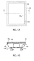
- FIGs. 5A and 5B show the state where fabric is set on a platen.
- FIG. 5A is a plan view
- FIG. 5B is a cross-sectional view taken along the line A-A of FIG. 5A .
- the platen 42 is a rectangle having the longitudinal direction in a direction orthogonal to the reciprocating direction of the carriage 54 from the planner view and includes a support surface 46 that supports a T-shirt 100.
- the lower surface of the platen 42 at the farthest side in a direction perpendicular to the paper surface in FIG. 5B is linked to the slide mechanism 41 at the facing position via a support member 47.
- each of upper parts of both ends of the platen 42, parallel with the longitudinal direction has an arc shape.
- the fixing frame 45 is configured so that a frame having a L-shaped cross section covers the four sides of the support surface 46 of the platen 42.
- An opening 45a having an opening area slightly smaller than the area of the support surface 46 of the platen 42 is formed on the surface facing the support surface 46 of the platen 42 in the fixing frame 45.
- the inner surface of the fixing frame 45 facing the side surface of the platen 42 is provided with an anti-slipping member 49 made of rubber.
- This anti-slipping member 49 allows the T-shirt 100 to be set in the state where the T-shirt is stretched in two directions of the longitudinal direction (longitudinal direction of the T-shirt 100) and the short direction (short direction of the T-shirt 100) of the support surface 46 of the platen 42 and allows the T-shirt 100 to be held without creases in the case where the T-shirt 100 is set on the platen 42.
- the T-shirt 100 is set from the hem side in such a manner that the T-shirt covers the support surface 46 of the platen 42 and is fixed with the fixing frame 45.
- the fixing frame 45 is provided rotatably by a rotation portion (not shown) provided at the end portion of the platen 42, positioned at the farthest side in a direction perpendicular to the paper surface in FIG. 5B , and the T-shirt 100 is fixed between the platen 42 and the fixing frame 45 by rotating the fixing frame 45 so as to fit to the platen 42 after covering the platen 42 with the T-shirt 100.
- the ink-jet printer 31 is provided with a cover 43, and the cover 43 covers the ink-jet heads 55, the slide mechanism 41, and the like to protect them.
- the cover 43 is diagramlly illustrated by chain double-dashed lines in FIG. 4 in order to show the inside of the cover 43 in detail.
- An operation panel 44 provided with a liquid crystal panel and operation buttons is arranged at a predetermined position of the right upper portion of the front cover 43.
- the five ink-jet heads 55 shown in FIG. 4 correspond to the respective five color inks (yellow, magenta, cyan, black, and white), are arranged in parallel along the reciprocating direction of the carriage 54, and are in communication with the respective ink cartridges 60 via the flexible tubes 62 and the ink tanks 61.
- the white ink is the pigment ink for ink-jet recording.
- the other inks may be inks in general.
- a conventionally known configuration may be employed, for example (for example, see JP 2004-291461 A ).
- a head unit including ejection units that eject the respective four color inks (yellow, magenta, cyan, and black) and a head unit including an ejection unit that ejects a white ink may be arranged in a direction orthogonal to the reciprocating direction of the carriage 54.
- the above-described linkage of the ink cartridges 60 and the ink tanks 61 via the flexible tubes 62 allows the inks in the ink cartridges 60 to be supplied to the ink tanks 61 and allows the ink cartridges 60 to be provided at the positions where they are easily exchangeable. Therefore, when the inks in the ink cartridges 60 run out, the ink cartridges 60 may be easily changed.
- the ink-jet heads 55 are arranged so as to form a small gap between the lower surfaces and the support surface 46 of the platen 42, and a portion to be recorded of the T-shirt 100 set on the platen 42 is fed to the gap when an image is recorded on the T-shirt 100.
- a desired color image may be recorded on the T-shirt.
- the recording control unit 70 shown in FIG. 3 is, for example, configured using a general-purpose personal computer (PC) and includes a main body 71, a display as a display section 72, and a keyboard 73 and a mouse (pointing device) 74 as an operation section 75.
- PC personal computer
- FIG. 6 is a block diagram showing a configuration of the recording control unit 70 shown in FIG. 3 .
- the recording control unit 70 includes a CPU (Central Processing Unit) 81, a ROM (Read Only Memory) 82, a RAM (Random Access Memory) 83, an HD (Hard Disk) 84, an operation section 75, a display section 72, and an interface (I/F) 85, and they are connected via a bus.
- the CPU 81, the ROM 82, the RAM 83, and the HD 84 are incorporated into the main body 71 of the recording control unit 70, and the operation section 75 is composed of the keyboard 73 and the mouse 74.
- the HD 84 stores various programs for use in control of the operation of the recording control unit 70.
- the HD 84 further stores various image data produced by software and various data according to the kind of fabric such as T-shirt.
- the CPU 81 performs various operations and processes on the basis of signals input with the operation section 75 and various programs and data stored in the ROM 82, the RAM 83, and the HD 84. Then, data and the like are sent to the ink-jet printer 31 via the interface 85.
- the RAM 83 is a volatile storage device which is readable and writable and stores results of the various operations and the like obtained in the CPU 81.
- the interface 85 is connected to an interface of the ink-jet printer 31 and allows the printing control apparatus 70 and the ink-jet printer 31 to communicate with each other.
- FIG. 7 is a functional block diagram of the recording control unit 70.
- the recording control unit 70 includes an image data acquisition section 90 and an image data storage section 91.
- the image data acquisition section 90 is realized by the CPU 81
- the image data storage section 91 is composed of the RAM 83 and/or the HD 84.
- the image data acquisition section 90 has a known function for use in production of image data and produces various image data on the basis of signals input from the keyboard 73 or the mouse 74 by an operator.
- the image data storage section 91 stores image data collected from removable storage media such as a CD-ROM, an FD, and an MO and the Internet and image data acquired by the image data acquisition section 90.
- a desired image is recorded on a T-shirt 100 using the ink-jet recording apparatus 30 of the present example as follows, for example.
- image data desired to be recorded on a T-shirt 100 are acquired using a keyboard 73 and a mouse 74 of a PC.
- image data is produced using software installed in the PC, or image data previously stored in a HD 84 is selected.
- the T-shirt 100 is fixed on a platen 42. That is, the T-shirt 100 is overlaid on the platen 42 from the hem of the T-shirt 100 and is fixed with a fixing frame 45 along a supporting surface 46 of the platen 42 without creases.
- the image data is sent to an ink-jet printer 31 via an interface 85, inks are ejected from ink-jet heads 55 on the basis of the image data, and the T-shirt 100 fixed on the platen 42 is subjected to recording.
- the pigment ink for ink-jet recording is superior in dispersibility.
- the user is not required to shake the ink cartridges 60 to stir the pigment ink for ink-jet recording.
- the deposition of the pigment in an ink flow path of the ink-jet printer 31 and the clogging of the ink-jet heads 55 by the pigment are suppressed.
- the pigment ink for ink-jet recording is favorably used in formation of a white base layer at the time when color recording is performed on a deep color fabric.
- porous silica (SiO 2 ) particles coated with an inorganic pigment layer containing titanium oxide (TiO 2 ) were produced.
- Thickness of TiO 2 film Thiickness of the inorganic pigment layer
- the thickness of the TiO 2 film was determined by actual measurement using a scanning electron microscope.
- the particle size was determined by dynamic light scattering using Microtrac UPA-EX150 manufactured by NIKKISO CO., LTD.
- the SiO 2 /TiO 2 was determined by actual measurement using a scanning electron microscope (EDS: energy dispersive X-ray spectrometry).
- the density was measured using Micro-Ultrapycnometer 1000 manufactured by Malvern.
- the sedimentation velocity in a solvent (water) was measured by centrifugal separation using LUMiSizer 610 manufactured by LUM.
- the pigments A to J had low sedimentation velocities in a solvent compared with the comparative pigments having the same TiO 2 film thicknesses and the same particle sizes as the pigments A to J, in which pore openings of the porous SiO 2 particles were completely filled with TiO 2 , the pigments A to J are superior in dispersibility in a solvent.
- the pigments B to G having densities of 1.7 g/cm 3 to 2.8 g/cm 3 had the sedimentation velocities of about 1/2 or less, compared with the comparative pigments, the pigments B to G are more superior in dispersibility in a solvent.
- the pigments B to G had L* of about 60 or more, the pigments B to G are more superior in also brightness.
Landscapes
- Chemical & Material Sciences (AREA)
- Organic Chemistry (AREA)
- Engineering & Computer Science (AREA)
- Textile Engineering (AREA)
- Chemical Kinetics & Catalysis (AREA)
- Wood Science & Technology (AREA)
- Life Sciences & Earth Sciences (AREA)
- Materials Engineering (AREA)
- Dispersion Chemistry (AREA)
- Health & Medical Sciences (AREA)
- Medicinal Chemistry (AREA)
- Polymers & Plastics (AREA)
- Inks, Pencil-Leads, Or Crayons (AREA)
- Ink Jet (AREA)
- Ink Jet Recording Methods And Recording Media Thereof (AREA)
- Pigments, Carbon Blacks, Or Wood Stains (AREA)
- Coloring (AREA)
Abstract
Description
- As an inorganic pigment for use in a pigment ink, a multilayer pigment obtained by coating a base material such as titanium oxide or SiO2 with layers each having a high refractive index such as TiO2 is known (see
JP 2010-507009 A - However, sedimentation of the above-mentioned inorganic pigment in the pigment ink is generated over time. Therefore, for example, in the case where printing is performed after it has not been performed for a long period of time, the user shakes an ink cartridge to stir the pigment ink before using.
- The pigment for ink-jet recording comprises: a porous particle; a sealing agent; and an inorganic pigment layer comprising an inorganic pigment, the sealing agent is arranged in a pore opening of the porous particle, and the inorganic pigment layer is formed on the surface of the porous particle.
- The pigment for ink-jet recording comprises: a porous particle; and an inorganic pigment layer comprising an inorganic pigment, the inorganic pigment layer is formed on the surface of the porous particle, and the inorganic pigment is not present in a pore opening of the porous particle inside the inorganic pigment layer.
- In the pigment for ink-jet recording, the sealing agent is arranged in a pore opening of the porous particle, and the porous particle is coated with the inorganic pigment layer. Thus, the pigment for ink-jet recording becomes a hollow pigment with a low density and is superior in dispersibility in a solvent.
-
- [
FIG. 1] FIG. 1 shows figures describing an example of a method for producing a pigment for ink-jet recording. - [
FIG. 2] FIG. 2 is a schematic perspective view showing an example of the configuration of an ink-jet recording apparatus. - [
FIG. 3] FIG. 3 is a schematic view showing another example of the configuration of an ink-jet recording apparatus. - [
FIG. 4] FIG. 4 is a front view showing an example of the configuration of an ink-jet printer in the ink-jet recording apparatus shown inFIG. 3 . - [
FIG. 5] FIG. 5A is a plan view showing the state where fabric is set to a platen of the ink-jet recording apparatus shown inFIG. 3 .FIG. 5B is a cross-sectional view taken along line A-A ofFIG. 5A . - [
FIG. 6] FIG. 6 is a block diagram showing the configuration of a recording control unit of the ink-jet recording apparatus shown inFIG. 3 . - [
FIG. 7] FIG. 7 is a functional block diagram of the recording control unit of the ink-jet recording apparatus shown inFIG. 3 . - In the present invention, "the inorganic pigment is not present in a pore opening of the porous particle" encompasses the case where "the inorganic pigment is not substantially present in a pore opening of the porous particle". "The inorganic pigment is not substantially present in a pore opening of the porous particle" means that the pigment for ink-jet recording may contain a small amount of the inorganic pigment in the pore opening within the favorable range of the pigment density described below.
- As mentioned above, the pigment for ink-jet recording comprises: a porous particle; a sealing agent; and an inorganic pigment layer comprising an inorganic pigment, the sealing agent is arranged in a pore opening of the porous particle, and the inorganic pigment layer is formed on the surface of the porous particle.
- Examples of the porous particle include a porous silicon oxide particle such as porous silica (SiO2) particle, a porous alminosilicate particle such as zeolite, a porous aluminium oxide particle, a porous zirconium oxide particle, and active carbon, and the porous particle is, for example, a porous silica particle.
- The sealing agent is not particularly limited as long as it is arranged in a pore opening of the porous particle and is, for example, a chemical compound of organic silicon. Examples of the chemical compound of organic silicon include alkoxysilane such as tetraethoxysilane (TEOS), trialkylmonosilane such as trimethylmonosilane, alkylsilane such as hexamethyldisilane, and fluoroalkylsilane such as a silane coupling agent having a perfluoroalkyl group.
- The inorganic pigment is not particularly limited, and examples thereof include titanium oxide, sulfate of alkali earth metal, carbonate of alkali earth metal, silica (for example, fine-powdered silicic acid, synthesized silicate), calcium silicate, alumina, hydrated alumina, zinc oxide, talc, and clay. Any one of them may be used alone, or two or more of them may be used in combination. Among them, the inorganic pigment is, for example, titanium oxide.
- The method for producing a pigment for ink-jet recording is described below with reference to (a) to (c) in
FIG. 1 . The method, however, is merely an example and the pigment for ink-jet recording may be produced by another method. - As shown in (a) and (b) in
FIG. 1 , asealing agent 4 is arranged on the entire surface including the outerperipheral surface 2 of aporous particle 1 and theinner surface 3a of apore opening 3. - As the
porous particle 1, a commercially available porous particle or a self-prepared porous particle may be used. The porous silica particle may be prepared by causing the inside and the surface of an aggregate of ultrafine powder such as as calcium carbonate or the like as a base particle (core) to be immersed in and coated with silica, then dissolving the ultrafine powder in acid, and thereafter drying the ultrafine powder, for example. - The arrangement of the
sealing agent 4 may be performed by a reflux method or a supercritical method using an autoclave, for example. - Then, as shown in (c) in
FIG. 1 , the inorganic pigment layer 5 comprising an inorganic pigment is formed on the surface of theporous particle 1. The inorganic pigment layer 5 may be formed by stirring a solution containing theporous particle 1 and the inorganic pigment with ultrasound, then subjecting the solution to centrifugal separation, and thereafter washing, drying, and firing the obtained precipitate, for example. At that time, thesealing agent 4 is arranged in the pore opening 3 of theporous particle 1. Thus, the entering of the inorganic pigment into thepore opening 3 is significantly suppressed, and a hollow pigment with a low density can be obtained. - The density of the pigment for ink-jet recording is, for example, 1.7 g/cm3 to 2.8 g/cm3. With the density range, the sedimentation velocity in a solvent may be about 1/2 or less of the case where the inorganic pigment is entered into the
pore opening 3 of theporous particle 1, and thepore opening 3 is completely filled with the inorganic pigment, and the pigment for ink-jet recording may be further superior in dispersibility in a solvent. Moreover, in the case where titanium oxide is used as the inorganic pigment, the pigment for ink-jet recording with further superior brightness (L*) may be obtained. - The application of the pigment for ink-jet recording is not particularly limited, and the pigment for ink-jet recording may be applied widely in various inks, various paints, and the like as well as a pigment ink for ink-jet recording described below, for example.
- Then, a pigment ink for ink-jet recording (hereinafter also referred to as a "pigment ink" or an "ink".) is described below. The pigment ink for ink-jet recording comprises the pigment for ink-jet recording. The pigment ink for ink-jet recording may be used in ink-jet recording on recording paper, a transparent sheet such as an OHP sheet, or the like or may be used in ink-jet recording on fabric.
- The amount of the pigment for ink-jet recording to be added in the pigment ink for ink-jet recording is not particularly limited and is, for example, 1 wt% to 25 wt%, 3 wt% to 20 wt%, 5 wt% to 15 wt%, relative to the total amount of the pigment ink.
- The pigment ink for ink-jet recording may further contain a coloring agent other than the pigment for ink-jet recording. Examples of the coloring agent other than the pigment for ink-jet recording include a pigment other than the pigment for ink-jet recording and a dye.
- The pigment ink for ink-jet recording may further contain a pigment dispersant in order to further improve dispersibility of the pigment. The pigment dispersant may be, for example, a polyacrylic resin. The amount of the pigment dispersant to be added relative to the total amount of the pigment ink is, for example, 0 wt% to 10 wt%, 2 wt% to 7 wt%.
- The pigment ink for ink-jet recording may further contain water. The water is, for example, distilled water, ion-exchange water, or pure water. The amount of the water to be added relative to the total amount of the pigment ink for ink-jet recording is, for example, the balance of the pigment ink for ink-jet recording, excluding other components.
- The pigment ink for ink-jet recording may further contain a humectant. The humectant prevents the ink from drying at the tip of the ink-jet head, for example. The humectant is not particularly limited, and examples thereof include lower alcohols such as methyl alcohol, ethyl alcohol, n-propyl alcohol, isopropyl alcohol, n-butyl alcohol, sec-butyl alcohol, or tert-butyl alcohol; amide such as dimethylformamide or dimethylacetamide; ketone such as acetone; ketoalcohol such as diacetone alcohol; ether such as tetrahydrofuran or dioxane; polyether such as polyalkylene glycol; polyhydric alcohol such as alkylene glycol, glycerin, or trimethylol propane; 2-pyrrolidone; N-methyl-2-pyrrolidone; and 1,3-dimethyl-2-imidazolidinone. Examples of the polyalkylene glycol include polyethylene glycol and polypropylene glycol. Examples of the alkylene glycol include ethylene glycol, propylene glycol, diethylene glycol, triethylene glycol, dipropylene glycol, tripropylene glycol, thiodiglycol, and hexylene glycol. Any one of them may be used alone, or two or more of them may be used in combination. Among them, the humectant is, for example, polyhydric alcohol such as alkylene glycol or glycerin. The amount of the humectant to be added relative to the total amount of the pigment ink for ink-jet recording is, for example, 0 wt% to 60 wt%, 3 wt% to 50 wt%.
- The pigment ink for ink-jet recording may further contain a surfactant. The surfactant may cause the surface tension of the pigment ink for ink-jet recording and the dispersibility of the pigment to be improved. The surfactant is not particularly limited, and examples thereof include: anionic surfactants produced by Kao Corporation such as EMAL® series, LATEMUL® series, VENOL® series, NEOPELEX® series, NS SOAP, KS SOAP, OS SOAP, and PELEX® series; anionic surfactants produced by Lion Corporation such as LIPOLAN® series, LIPON® series, SUNNOL® series, LIPOTAC® TE, ENAGICOL® series, LIPAL® series, and LOTAT® series; nonionic surfactants produced by Kao Corporation such as EMULGEN® series, RHEODOL® series, EMASOL® series, EXCEL® series, EMANON® series, AMIET® series, and AMINON® series; nonionic surfactants produced by Lion Corporation such as DOBANOX® series, LEOCOL® series, LEOX® series, LAOL, LEOCON® series, LIONOL® series, CADENAX® series, LIONON® series, and LEOFAT® series; and cationic surfactants produced by DAI-ICHI KOGYO SEIYAKU CO., Ltd. such as CATIOGEN® ES-OW and CATIOGEN® ES-L. Any one of them may be used alone, or two or more of them may be used in combination. The amount of the surfactant to be added relative to the total amount of the pigment ink for ink-jet recording is, for example, 0 wt% to 2 wt%, 0.01 wt% to 1.5 wt%, 0.01 wt% to 1 wt%.
- The pigment ink for ink-jet recording may further contain a conventionally known additive if necessary. Examples of the additive include a pH adjuster, a viscosity modifier, a surface tension modifier, and a mildewproofing agent. Examples of the viscosity modifier include polyvinyl alcohol, cellulose, and a water-soluble resin.
- In the case where the pigment ink for ink-jet recording is used in ink-jet recording on fabric, the pigment ink may further contain a resin emulsion.
- The resin emulsion is not particularly limited, and examples thereof include an acrylic resin emulsion, an urethane resin emulsion, and a styrene resin emulsion. The resin emulsion is, for example, an acrylic emulsion or an urethane resin emulsion. As the resin emulsion, a commercially available resin emulsion may be used, for example. Any one of them may be used alone, or two or more of them may be used in combination. The amount of the resin emulsion to be added in the pigment ink for ink-jet recording is not particularly limited and is, for example, 0 wt% to 30 wt%, 1 wt% to 20 wt%, 2 wt% to 15 wt%, relative to the total amount of the pigment ink for ink-jet recording.
- The pigment ink for ink-jet recording may be prepared by uniformly mixing the pigment for ink-jet recording and other components to be added and removing an insoluble matter with a filter or the like, for example.
- The pigment ink for ink-jet recording comprises the pigment for ink-jet recording and is thus superior in dispersibility. Therefore, as mentioned below, in an ink cartridge containing the pigment ink for ink-jet recording, generation of a precipitate (sedimentation of the pigment) is suppressed. Moreover, by the use of the pigment ink for ink-jet recording, the deposition of the pigment in an ink flow path of an ink-jet recording apparatus and the clogging of an ink-jet head by the pigment are suppressed.
- An ink cartridge contains an ink, and the ink is the pigment ink. The pigment ink is superior in dispersibility, so that generation of the precipitate (sedimentation of the pigment) in the ink cartridge is suppressed. As a main body of the ink cartridge, a conventionally known main body may be used, for example.
- The ink-jet recording apparatus and the ink-jet recording method are described below.
- The ink-jet recording apparatus includes: an ink storing potion; and an ink ejection unit, an ink stored in the ink storing portion is ejected by the ink ejection unit, and the ink storing portion stores the pigment ink for ink-jet recording.
- The ink-jet recording method includes: ejecting an ink to a recording medium by an ink-jet recording to record, and the pigment ink for ink-jet recording is used as the ink.
- The ink-jet recording method may be performed using the ink-jet recording apparatus, for example. Examples of the recording include printing of letters and images and printing.
- An ink-
jet recording apparatus 10 of the present example shown inFIG. 2 is for use in recording on recording paper, a transparent sheet such as an OHP sheet, or the like. As shown inFIG. 2 , this ink-jet recording apparatus 10 includes, as main components, fiveink cartridges 12, an ink ejection unit (ink-jet head) 13, ahead unit 14, acarriage 15, adrive unit 16, aplaten roller 17, and apurge unit 18. - Each of the five
ink cartridges 12 contains any one of the yellow, magenta, cyan, black, and white inks. For example, the white ink is the pigment ink for ink-jet recording. As the other inks, general inks may be used. The ink-jet head 13 set in thehead unit 14 performs recording on a recording medium (for example, recording paper) P. The fiveink cartridges 12 and thehead unit 14 are mounted in thecarriage 15. Thedrive unit 16 reciprocates thecarriage 15 in a straight line direction. As thedrive unit 16, a conventionally known drive unit may be used, for example (for example, seeJP 2008-246821 A platen roller 17 extends in a reciprocating direction of thecarriage 15 and is arranged so as to be opposed to the ink-jet head 13. - The
purge unit 18 draws poor inks containing air bubbles and the like trapped inside the ink-jet head 13. As thepurge unit 18, a conventionally known purge unit may be used, for example (for example, seeJP 2008-246821 A - On the
platen roller 17 side of thepurge unit 18, awiper member 20 is arranged at a predetermined position so as to be adjacent to thepurge unit 18. Thewiper member 20 is formed into a spatula shape and wipes a nozzle-formed surface of the ink-jet head 13 with the movement of thecarriage 15. InFIG. 2 , acap 19 covers a plurality of nozzles of the ink-jet head 13, which returns to the reset position after completion of the recording, in order to prevent the inks from drying. - The five
ink cartridges 12 are mounted in onecarriage 15 together with thehead unit 14 in the ink-jet recording apparatus 10 of the present example. However, in the ink-jet recording apparatus 10, each of the fiveink cartridges 12 may be mounted in a carriage that is different from a carriage in which thehead unit 14 is mounted. Each of the fiveink cartridges 12 may not be mounted in thecarriage 15 and may be arranged and fixed in the ink-jet recording apparatus 10. In these aspects, for example, each of the fiveink cartridges 12 and thehead unit 14 mounted in thecarriage 15 are linked via a tube or the like, and the ink is supplied from each of the fiveink cartridges 12 to thehead unit 14. - The ink-jet recording using this ink-
jet recording apparatus 10 is performed as described below, for example. First, recording paper P is fed from a paper cassette (not shown) provided on or side of or under the ink-jet recording apparatus 10. Then, the recording paper P is introduced between the ink-jet head 13 and theplaten roller 17. Thereafter, the introduced recording paper P is subjected to the predetermined recording with inks ejected from the ink-jet head 13. The pigment ink for ink-jet recording is superior in dispersibility. Thus, the user is not required to shake theink cartridges 12 to stir the pigment ink for ink-jet recording. Moreover, by using the pigment ink for ink-jet recording, the deposition of the pigment in an ink flow path of the ink-jet recording apparatus 10 and the clogging of the ink-jet head 13 by the pigment are suppressed. The recording paper P after the recording is discharged from the ink-jet recording apparatus 10. Mechanisms of feeding and discharging the recording paper P are omitted inFIG. 2 . The pigment ink for ink-jet recording is favorably used in formation of a white base layer at the time when a color recording is performed on a transparent sheet such as an OHP sheet. - In the apparatus shown in
FIG. 2 , a serial-type ink-jet head is employed. However, in the ink-jet recording apparatus, a line-type ink jet head may be employed. - An ink-
jet recording apparatus 30 of the present example shown inFIG. 3 is for use in recording on fabric. As shown inFIG. 3 , this ink-jet recording apparatus 30 is configured so that an ink-jet printer 31 that performs recording of the predetermined image on fabric by ejecting inks and arecording control unit 70 that acquires image data of the predetermined image and controls the ink-jet printer 31 via an interface. - As shown in
FIG. 4 , the ink-jet printer 31 is provided with aframe 52. Theframe 52 includes ahorizontal portion 52h positioned on the bottom of theprinter 31 and twovertical portions 52v extending perpendicularly to and upward from the respective ends of thehorizontal portion 52h. InFIG. 4 , identical parts to those inFIG. 3 are indicated by identical reference numerals, and the same applies to the subsequent figures. - A
slide rail 53 is supported in such a manner that the upper portions of the respective twovertical portions 52v are mutually linked. Acarriage 54 is mounted on theside rail 53 slidably in a longitudinal direction (main scanning direction) of theslide rail 53. The lower surface of thiscarriage 54 is provided with five piezoelectric ink-jet heads (ink ejection units) 55 arranged at the respective predetermined positions in order to eject five color inks. -
Pulleys vertical portions 52v, and a motor shaft of amotor 58 supported by thevertical portion 52v is linked to thepulley 56. Anendless belt 59 is extended between thepulleys carriage 54 is fixed to an appropriate portion of thisendless belt 59. - With such configuration, the
carriage 54 reciprocates linearly along the longitudinal direction (main scanning direction) of theslide rail 53 as themotor 58 rotates thepulley 56 in the normal or reverse direction, and consequently the ink-jet heads 55 reciprocate. - The
respective mounting portions 50 that detachably mountink cartridges 60 are formed on the twovertical portions 52v. Among the two mountingportions 50, one may hold twocolor ink cartridges 60, and the other may hold threecolor ink cartridges 60, and the ink bags (not shown) formed inside therespective ink cartridges 60 are connected to the respective fiveink tanks 61 positioned in the upper parts of the ink-jet heads 55 viaflexible tubes 62. The fiveink tanks 61 are in communication with the respective ink-jet heads 55 as described below, so that the inks are supplied from therespective ink cartridges 60 to the respective ink-jet heads 55. - A
slide mechanism 41 is provided on thehorizontal portion 52h of theframe 52, and a platen (support) 42 is supported on theslide mechanism 41. Thisplaten 42 is provided with a fixing frame (fixing unit) 45 so that fabric is set to a position at which a portion on which recording is performed faces up in a flat state without creases. Although the ink-jet printer 31 of the present example performs ink-jet recording on a T-shirt that has been sewed, it may be applied to fabric in general. Further, although the number ofplatens 42 is one in the ink-jet printer 32 of the present example, the number is not limited to one and may be increased if necessary. For example, by using the ink-jet printer having two platens, fixation of a T-short to one of the platens may be performed while an image is recorded on another T-shirt fixed on another platen. Therefore, working efficiency may be increased. - Further, a platen moving mechanism (not shown) is arranged at a predetermined position in order to reciprocate the
platen 42 in a direction perpendicular to the paper surface inFIG. 4 (the sliding direction of theslide mechanism 41, which forms an auxiliary scanning direction of the ink-jet printer 31). A rack, a pinion mechanism, a mechanism using an endless belt, or the like may be employed as the platen moving mechanism. -
FIGs. 5A and 5B show the state where fabric is set on a platen.FIG. 5A is a plan view, andFIG. 5B is a cross-sectional view taken along the line A-A ofFIG. 5A . As shown inFIGs. 5A and 5B , theplaten 42 is a rectangle having the longitudinal direction in a direction orthogonal to the reciprocating direction of thecarriage 54 from the planner view and includes asupport surface 46 that supports a T-shirt 100. The lower surface of theplaten 42 at the farthest side in a direction perpendicular to the paper surface inFIG. 5B is linked to theslide mechanism 41 at the facing position via asupport member 47. Further, each of upper parts of both ends of theplaten 42, parallel with the longitudinal direction, has an arc shape. - The fixing
frame 45 is configured so that a frame having a L-shaped cross section covers the four sides of thesupport surface 46 of theplaten 42. Anopening 45a having an opening area slightly smaller than the area of thesupport surface 46 of theplaten 42 is formed on the surface facing thesupport surface 46 of theplaten 42 in the fixingframe 45. Further, the inner surface of the fixingframe 45 facing the side surface of theplaten 42 is provided with ananti-slipping member 49 made of rubber. Thisanti-slipping member 49 allows the T-shirt 100 to be set in the state where the T-shirt is stretched in two directions of the longitudinal direction (longitudinal direction of the T-shirt 100) and the short direction (short direction of the T-shirt 100) of thesupport surface 46 of theplaten 42 and allows the T-shirt 100 to be held without creases in the case where the T-shirt 100 is set on theplaten 42. At the time of setting the T-shirt 100 on theplaten 42, the T-shirt 100 is set from the hem side in such a manner that the T-shirt covers thesupport surface 46 of theplaten 42 and is fixed with the fixingframe 45. Further, the fixingframe 45 is provided rotatably by a rotation portion (not shown) provided at the end portion of theplaten 42, positioned at the farthest side in a direction perpendicular to the paper surface inFIG. 5B , and the T-shirt 100 is fixed between theplaten 42 and the fixingframe 45 by rotating the fixingframe 45 so as to fit to theplaten 42 after covering theplaten 42 with the T-shirt 100. - The ink-
jet printer 31 is provided with acover 43, and thecover 43 covers the ink-jet heads 55, theslide mechanism 41, and the like to protect them. Note here that thecover 43 is perspectivally illustrated by chain double-dashed lines inFIG. 4 in order to show the inside of thecover 43 in detail. Anoperation panel 44 provided with a liquid crystal panel and operation buttons is arranged at a predetermined position of the right upper portion of thefront cover 43. - The five ink-jet heads 55 shown in
FIG. 4 correspond to the respective five color inks (yellow, magenta, cyan, black, and white), are arranged in parallel along the reciprocating direction of thecarriage 54, and are in communication with therespective ink cartridges 60 via theflexible tubes 62 and theink tanks 61. For example, the white ink is the pigment ink for ink-jet recording. The other inks may be inks in general. As the configuration for supplying inks to the ink-jet heads, a conventionally known configuration may be employed, for example (for example, seeJP 2004-291461 A carriage 54. - The above-described linkage of the
ink cartridges 60 and theink tanks 61 via theflexible tubes 62 allows the inks in theink cartridges 60 to be supplied to theink tanks 61 and allows theink cartridges 60 to be provided at the positions where they are easily exchangeable. Therefore, when the inks in theink cartridges 60 run out, theink cartridges 60 may be easily changed. - The ink-jet heads 55 are arranged so as to form a small gap between the lower surfaces and the
support surface 46 of theplaten 42, and a portion to be recorded of the T-shirt 100 set on theplaten 42 is fed to the gap when an image is recorded on the T-shirt 100. With this configuration, by reciprocating the ink-jet heads 55 by thecarriage 54 while ejecting each of the color inks from plural ejection nozzles with micro-diameters formed on the bottom surfaces of the ink-jet heads 55 on the T-shirt 100, a desired color image may be recorded on the T-shirt. - The
recording control unit 70 shown inFIG. 3 is, for example, configured using a general-purpose personal computer (PC) and includes amain body 71, a display as adisplay section 72, and akeyboard 73 and a mouse (pointing device) 74 as anoperation section 75. -
FIG. 6 is a block diagram showing a configuration of therecording control unit 70 shown inFIG. 3 . Therecording control unit 70 includes a CPU (Central Processing Unit) 81, a ROM (Read Only Memory) 82, a RAM (Random Access Memory) 83, an HD (Hard Disk) 84, anoperation section 75, adisplay section 72, and an interface (I/F) 85, and they are connected via a bus. TheCPU 81, theROM 82, theRAM 83, and theHD 84 are incorporated into themain body 71 of therecording control unit 70, and theoperation section 75 is composed of thekeyboard 73 and themouse 74. - The
HD 84 stores various programs for use in control of the operation of therecording control unit 70. TheHD 84 further stores various image data produced by software and various data according to the kind of fabric such as T-shirt. TheCPU 81 performs various operations and processes on the basis of signals input with theoperation section 75 and various programs and data stored in theROM 82, theRAM 83, and theHD 84. Then, data and the like are sent to the ink-jet printer 31 via theinterface 85. TheRAM 83 is a volatile storage device which is readable and writable and stores results of the various operations and the like obtained in theCPU 81. Theinterface 85 is connected to an interface of the ink-jet printer 31 and allows theprinting control apparatus 70 and the ink-jet printer 31 to communicate with each other. -
FIG. 7 is a functional block diagram of therecording control unit 70. As shown inFIG. 7 , therecording control unit 70 includes an imagedata acquisition section 90 and an imagedata storage section 91. In the present example, the imagedata acquisition section 90 is realized by theCPU 81, and the imagedata storage section 91 is composed of theRAM 83 and/or theHD 84. - The image
data acquisition section 90 has a known function for use in production of image data and produces various image data on the basis of signals input from thekeyboard 73 or themouse 74 by an operator. The imagedata storage section 91 stores image data collected from removable storage media such as a CD-ROM, an FD, and an MO and the Internet and image data acquired by the imagedata acquisition section 90. - A desired image is recorded on a T-
shirt 100 using the ink-jet recording apparatus 30 of the present example as follows, for example. First, image data desired to be recorded on a T-shirt 100 are acquired using akeyboard 73 and amouse 74 of a PC. In the acquisition of the image data, image data is produced using software installed in the PC, or image data previously stored in aHD 84 is selected. - Then, the T-
shirt 100 is fixed on aplaten 42. That is, the T-shirt 100 is overlaid on theplaten 42 from the hem of the T-shirt 100 and is fixed with a fixingframe 45 along a supportingsurface 46 of theplaten 42 without creases. - Subsequently, when an operator instructs that recording is performed, the image data is sent to an ink-
jet printer 31 via aninterface 85, inks are ejected from ink-jet heads 55 on the basis of the image data, and the T-shirt 100 fixed on theplaten 42 is subjected to recording. As in the apparatus shown inFIG. 2 , the pigment ink for ink-jet recording is superior in dispersibility. Thus, the user is not required to shake theink cartridges 60 to stir the pigment ink for ink-jet recording. Moreover, by using the pigment ink for ink-jet recording, the deposition of the pigment in an ink flow path of the ink-jet printer 31 and the clogging of the ink-jet heads 55 by the pigment are suppressed. The pigment ink for ink-jet recording is favorably used in formation of a white base layer at the time when color recording is performed on a deep color fabric. - The examples are described below. The present invention, however, is not limited by the following examples.
- As a pigment for ink-jet recording, porous silica (SiO2) particles coated with an inorganic pigment layer containing titanium oxide (TiO2) were produced.
- That is, first, 5.0 g of calcium carbonate having a particle size of 500 nm was weighed, and 18.00 ml of distilled water and 150.00 ml of ethanol were added thereto. The resultant mixture was then stirred with ultrasound for 10 minutes.
- Then, 15.0 ml of 25% aqueous ammonia solution and 4.0 ml of TEOS were added to the obtained dispersion liquid of the calcium carbonate, and the resultant mixture was refluxed at 50°C for 2 hours.
- Thereafter, the solution after the reflux was subjected to centrifugal separation, and the obtained precipitate was washed with ethanol. Then, the calcium carbonate was dissolved and removed with 3 mol/l hydrochloric acid. The precipitate was then again subjected to centrifugal separation, and the obtained precipitate was washed with ethanol and dried at 90°C for 24 hours.
- Subsequently, 1.0 ml of distilled water, 40 ml of ethanol, and 0.066 g of polyvinyl pyrolidone were added to the obtained porous SiO2 particle, which was then stirred with ultrasound for 15 minutes.
- Then, 40 ml of ethanol and tetrabutoxy titanium (TBOT) were added to a dispersion liquid of the obtained porous SiO2 particle, which was then stirred with ultrasound for 1 hour. By changing the charge amount of TBOT relative to the porous SiO2 particle, the thickness of the TiO2 film (the thickness of the inorganic pigment layer) was controlled. By increasing the charge amount of TBOT, the thickness of the TiO2 film (the thickness of the inorganic pigment layer) is increased.
- Subsequently, the solution after the stirring with ultrasound was subjected to centrifugal separation, and the obtained precipitate was then washed with ethanol and thereafter dried at 90°C for 24 hours. Thereafter, the precipitate was fired at 550°C for 3 hours. Thus, porous SiO2 particles (pigments A to J) coated with an inorganic pigment layer containing TiO2 were obtained.
- Various physical properties of the pigments A to J were measured by the following methods.
- The thickness of the TiO2 film was determined by actual measurement using a scanning electron microscope.
- The particle size was determined by dynamic light scattering using Microtrac UPA-EX150 manufactured by NIKKISO CO., LTD.
- The SiO2/TiO2 was determined by actual measurement using a scanning electron microscope (EDS: energy dispersive X-ray spectrometry).
- The density was measured using Micro-Ultrapycnometer 1000 manufactured by Malvern.
- The sedimentation velocity in a solvent (water) was measured by centrifugal separation using LUMiSizer 610 manufactured by LUM.
- 10 wt% of any of the pigments A to J, 15 wt% of a binder resin (MOWINYL (registered trademark) 6960, manufactured by Nippon Synthetic Chemical Industry Co., Ltd.), 20 wt% of a humectant (glycerin), and 50 wt% of water were uniformly mixed. Thus, each paint was prepared. Subsequently, the paint was drawn down onto a PET (polyethylene terephthalate) film using a bar coater #5, and the brightness (L*) was measured using a colorimeter.
- The measurement results of various physical properties of the pigments A to J are summarized in Table 1.
[Table 1] TiO2 film thickness (nm) Particle size (nm) SiO2/TiO2 (weight ratio) Density (g/cm3) Sedimentation velocity (cm/hr) Brightness (L*) Sedimentation velocity of Comparative pigment (cm/hr) Sedimentation velocity ratio to Comparative pigment Pigment A 4 508 6.530 1.5 0.025 54.2 0.166 0.151 Pigment B 10 520 2.551 1.7 0.036 59.3 0.173 0.209 Pigment C 21 542 1.163 2.0 0.057 63.9 0.188 0.301 Pigment D 25 550 0.962 2.1 0.064 69.2 0.194 0.331 Pigment E 30 560 0.787 2.2 0.074 72.5 0.201 0.367 Pigment F 44 588 0.508 2.5 0.100 76.3 0.222 0.453 Pigment G 64 628 0.325 2.8 0.139 77.3 0.253 0.551 Pigment H 80 660 0.245 3.0 0.171 78.1 0.279 0.613 Pigment J 97 694 0.190 3.2 0.206 78.8 0.309 0.667 - As summarized in Table 1, as can be seen from the fact that the pigments A to J had low sedimentation velocities in a solvent compared with the comparative pigments having the same TiO2 film thicknesses and the same particle sizes as the pigments A to J, in which pore openings of the porous SiO2 particles were completely filled with TiO2, the pigments A to J are superior in dispersibility in a solvent. Specifically, as can be seen from the fact that the pigments B to G having densities of 1.7 g/cm3 to 2.8 g/cm3 had the sedimentation velocities of about 1/2 or less, compared with the comparative pigments, the pigments B to G are more superior in dispersibility in a solvent. Moreover, as can be seen from the fact that the pigments B to G had L* of about 60 or more, the pigments B to G are more superior in also brightness.
- It will be obvious to those having skill in the art that many changes may be made in the above-described details of the particular aspects described herein without departing from the spirit or scope of the invention as defined in the appended claims.
Claims (12)
- A pigment for ink-jet recording, comprising:a porous particle;a sealing agent; andan inorganic pigment layer comprising an inorganic pigment, whereinthe sealing agent is arranged in a pore opening of the porous particle, andthe inorganic pigment layer is formed on the surface of the porous particle.
- A pigment for ink-jet recording, comprising:a porous particle; andan inorganic pigment layer comprising an inorganic pigment, whereinthe inorganic pigment layer is formed on the surface of the porous particle, andthe inorganic pigment is not present in a pore opening of the porous particle inside the inorganic pigment layer.
- The pigment for ink-jet recording according to claim 1 or 2, wherein
the inorganic pigment is at least one selected from the group consisting of titanium oxide, sulfate of alkali earth metal, carbonate of alkali earth metal, silica, calcium silicate, alumina, hydrated alumina, zinc oxide, talc, and clay. - The pigment for ink-jet recording according to any one of claims 1 to 3, wherein
the inorganic pigment comprises titanium oxide. - The pigment for ink-jet recording according to any one of claims 1 to 4, having a density of 1.7 g/cm3 to 2.8 g/cm3.
- The pigment for ink-jet recording according to any one of claims 1 to 5, wherein
the porous particle is at least one selected from the group consisting of a porous silicon oxide particle, a porous alminosilicate particle, a porous aluminium oxide particle, a porous zirconium oxide, and active carbon. - The pigment for ink-jet recording according to any one of claims 1 to 6, wherein
the porous particle is a porous silica particle. - The pigment for ink-jet recording according to any one of claims 1 to 7, wherein
the sealing agent is a chemical compound of organic silicon. - A pigment ink for ink-jet recording comprising the pigment for ink-jet recording according to any one of claims 1 and 3 to 8.
- The pigment ink for ink-jet recording according to claim 9, further comprising a resin emulsion, wherein
the pigment ink is used for forming an image on fabric. - The pigment ink for ink-jet recording according to claim 10, wherein
the resin emulsion comprises at least one of an acryl resin emulsion and an urethane resin emulsion. - A method for producing a pigment for ink-jet recording, comprising:sealing a pore opening of a porous particle with a sealing agent and thereafter forming an inorganic pigment layer comprising an inorganic pigment.
Applications Claiming Priority (1)
| Application Number | Priority Date | Filing Date | Title |
|---|---|---|---|
| JP2014053901A JP6152812B2 (en) | 2014-03-17 | 2014-03-17 | Inkjet recording pigment, inkjet recording pigment ink, and method for producing inkjet recording pigment |
Publications (2)
| Publication Number | Publication Date |
|---|---|
| EP2921532A1 true EP2921532A1 (en) | 2015-09-23 |
| EP2921532B1 EP2921532B1 (en) | 2025-09-24 |
Family
ID=52705950
Family Applications (1)
| Application Number | Title | Priority Date | Filing Date |
|---|---|---|---|
| EP15156905.0A Active EP2921532B1 (en) | 2014-03-17 | 2015-02-27 | Pigment for ink-jet recording, pigment ink for ink-jet recording, and method for producing pigment for ink-jet recording |
Country Status (4)
| Country | Link |
|---|---|
| US (1) | US9464200B2 (en) |
| EP (1) | EP2921532B1 (en) |
| JP (1) | JP6152812B2 (en) |
| CN (1) | CN104927486B (en) |
Families Citing this family (3)
| Publication number | Priority date | Publication date | Assignee | Title |
|---|---|---|---|---|
| JP2017179263A (en) | 2016-03-31 | 2017-10-05 | ブラザー工業株式会社 | Water-based white pigment ink for ink-jet recording and image-forming method |
| JP6414122B2 (en) | 2016-03-31 | 2018-10-31 | ブラザー工業株式会社 | Aqueous white pigment ink for inkjet recording |
| EP4282924A4 (en) * | 2021-04-13 | 2024-08-07 | Dic Corporation | Aqueous pigment dispersion and inkjet ink |
Citations (4)
| Publication number | Priority date | Publication date | Assignee | Title |
|---|---|---|---|---|
| JP2004291461A (en) | 2003-03-27 | 2004-10-21 | Brother Ind Ltd | Printing apparatus and printing method |
| US20070249736A1 (en) * | 2004-09-02 | 2007-10-25 | Catalysts & Chemicals Industries Co., Ltd. | Titanium-Containing Silica Sol and Process for Producing the Same, Antifouling Film and Base Material with Ink-Receptive Layer, and Method for Reproducing Recording Base Material |
| JP2008246821A (en) | 2007-03-30 | 2008-10-16 | Brother Ind Ltd | Pretreatment liquid, ink set, ink jet recording apparatus and ink jet recording method |
| JP2010507009A (en) | 2006-10-18 | 2010-03-04 | ビー・エイ・エス・エフ、コーポレーション | Multi-layer pigment showing color transfer |
Family Cites Families (15)
| Publication number | Priority date | Publication date | Assignee | Title |
|---|---|---|---|---|
| US5248556A (en) * | 1991-11-15 | 1993-09-28 | Manfred R. Kuehnle | Systhetic whitener pigment |
| JPH10152315A (en) * | 1996-11-21 | 1998-06-09 | Oji Yuka Synthetic Paper Co Ltd | Inorganic fine powder and its use |
| CN1735562A (en) * | 2003-01-17 | 2006-02-15 | 西巴特殊化学品控股有限公司 | A process for the production of porous inorganic materials or a matrix material containing nanoparticles |
| JP2005161583A (en) * | 2003-11-28 | 2005-06-23 | Brother Ind Ltd | White inkjet image forming method and apparatus on fabric |
| US7829161B2 (en) * | 2006-03-13 | 2010-11-09 | Eastman Kodak Company | Fusible inkjet recording element and related methods of coating and printing |
| JP5279065B2 (en) * | 2007-10-18 | 2013-09-04 | 国立大学法人 名古屋工業大学 | Surface-coated porous oxide particles and surface coating method of porous oxide particles |
| US8287637B2 (en) * | 2008-03-25 | 2012-10-16 | Xerox Corporation | Silica encapsulated organic nanopigments and method of making same |
| JP5342252B2 (en) * | 2009-01-28 | 2013-11-13 | 理想科学工業株式会社 | White ink for inkjet |
| JP5825640B2 (en) * | 2010-03-02 | 2015-12-02 | 大日精化工業株式会社 | Alkoxysilyl group-containing block copolymer, process for producing the block copolymer, resin-treated pigment, and pigment dispersion |
| JP2012007089A (en) * | 2010-06-25 | 2012-01-12 | Seiko Epson Corp | Ink composition, image recording method and laminate |
| US20140011954A1 (en) * | 2011-01-21 | 2014-01-09 | Dic Corporation | Method for producing porous silica particle, resin composition for antireflection coating, and article and antireflection film having antireflection coating |
| US8840719B2 (en) * | 2011-03-09 | 2014-09-23 | Tronox Llc | Titanium dioxide pigments and manufacturing method |
| JP2013082599A (en) * | 2011-10-13 | 2013-05-09 | Nagoya Institute Of Technology | Hollow silica nanoparticle complexed with nanoparticle and production method thereof |
| JP2013199603A (en) * | 2012-03-26 | 2013-10-03 | Seiko Epson Corp | Ink composition for inkjet printing |
| JP2013237601A (en) * | 2012-05-17 | 2013-11-28 | Nagoya Institute Of Technology | Hollow particle composed of surface-modified silica shell and method for producing the same |
-
2014
- 2014-03-17 JP JP2014053901A patent/JP6152812B2/en active Active
-
2015
- 2015-02-26 US US14/632,826 patent/US9464200B2/en active Active
- 2015-02-27 CN CN201510089198.XA patent/CN104927486B/en active Active
- 2015-02-27 EP EP15156905.0A patent/EP2921532B1/en active Active
Patent Citations (4)
| Publication number | Priority date | Publication date | Assignee | Title |
|---|---|---|---|---|
| JP2004291461A (en) | 2003-03-27 | 2004-10-21 | Brother Ind Ltd | Printing apparatus and printing method |
| US20070249736A1 (en) * | 2004-09-02 | 2007-10-25 | Catalysts & Chemicals Industries Co., Ltd. | Titanium-Containing Silica Sol and Process for Producing the Same, Antifouling Film and Base Material with Ink-Receptive Layer, and Method for Reproducing Recording Base Material |
| JP2010507009A (en) | 2006-10-18 | 2010-03-04 | ビー・エイ・エス・エフ、コーポレーション | Multi-layer pigment showing color transfer |
| JP2008246821A (en) | 2007-03-30 | 2008-10-16 | Brother Ind Ltd | Pretreatment liquid, ink set, ink jet recording apparatus and ink jet recording method |
Non-Patent Citations (1)
| Title |
|---|
| WANG C ET AL: "A facile method for the preparation of titania-coated magnetic porous silica and its photocatalytic activity under UV or visible light", COLLOIDS AND SURFACES. A, PHYSICACHEMICAL AND ENGINEERING ASPECTS, ELSEVIER, AMSTERDAM, NL, vol. 360, no. 1-3, 5 May 2010 (2010-05-05), pages 184 - 189, XP027009748, ISSN: 0927-7757, [retrieved on 20100303] * |
Also Published As
| Publication number | Publication date |
|---|---|
| CN104927486A (en) | 2015-09-23 |
| EP2921532B1 (en) | 2025-09-24 |
| JP6152812B2 (en) | 2017-06-28 |
| US9464200B2 (en) | 2016-10-11 |
| US20150259550A1 (en) | 2015-09-17 |
| CN104927486B (en) | 2019-04-02 |
| JP2015174960A (en) | 2015-10-05 |
Similar Documents
| Publication | Publication Date | Title |
|---|---|---|
| US10717297B2 (en) | Inkjet recording method and inkjet recording apparatus | |
| US10329443B2 (en) | Ink set and recording apparatus | |
| EP3219767B1 (en) | Ink set and ink-jet recording method | |
| DE60224422T2 (en) | Inkjet Recording Method, Logger, Ink, Logger Media, Record Material | |
| JP6308065B2 (en) | Inkjet ink set and inkjet recording method | |
| JP6638385B2 (en) | Aqueous ink set for inkjet recording and inkjet recording apparatus | |
| WO2004018211A1 (en) | Ink-jet recording apparatus and ink-jet recording method | |
| US20060272543A1 (en) | Pigment dispersion, inkjet ink using the pigment dispersion, method for preparing the pigment dispersion and image forming method using the inkjet ink | |
| JP2018172502A (en) | Aqueous ink for inkjet recording | |
| US11027556B2 (en) | Ink composition and ink jet recording set | |
| US9464200B2 (en) | Pigment for ink-jet recording, pigment ink for ink-jet recording, and method for producing pigment for ink-jet recording | |
| JP2016030776A (en) | Inkjet ink set and inkjet recording method | |
| JP2020105476A (en) | Ink set, image forming apparatus, and image forming method | |
| JP7451874B2 (en) | Recording method and recording device | |
| JP7792075B2 (en) | Recording method and recording device | |
| JP2023081488A (en) | Water-based ink for inkjet recording, inkjet recording method, inkjet recording apparatus, and ink container | |
| JP4700272B2 (en) | Inkjet recording method and recording apparatus | |
| CN114080435A (en) | Aqueous ink for inkjet recording and ink set | |
| JP2013121711A (en) | Recording device and recording method | |
| JP6228634B2 (en) | Ink jet recording ink and ink jet recording method | |
| CN1974687A (en) | Inkjet ink composition, inkjet cartridge including the same, and inkjet recording apparatus including the inkjet cartridge |
Legal Events
| Date | Code | Title | Description |
|---|---|---|---|
| PUAI | Public reference made under article 153(3) epc to a published international application that has entered the european phase |
Free format text: ORIGINAL CODE: 0009012 |
|
| AK | Designated contracting states |
Kind code of ref document: A1 Designated state(s): AL AT BE BG CH CY CZ DE DK EE ES FI FR GB GR HR HU IE IS IT LI LT LU LV MC MK MT NL NO PL PT RO RS SE SI SK SM TR |
|
| AX | Request for extension of the european patent |
Extension state: BA ME |
|
| 17P | Request for examination filed |
Effective date: 20160229 |
|
| RBV | Designated contracting states (corrected) |
Designated state(s): AL AT BE BG CH CY CZ DE DK EE ES FI FR GB GR HR HU IE IS IT LI LT LU LV MC MK MT NL NO PL PT RO RS SE SI SK SM TR |
|
| STAA | Information on the status of an ep patent application or granted ep patent |
Free format text: STATUS: EXAMINATION IS IN PROGRESS |
|
| 17Q | First examination report despatched |
Effective date: 20161115 |
|
| P01 | Opt-out of the competence of the unified patent court (upc) registered |
Effective date: 20230529 |
|
| GRAP | Despatch of communication of intention to grant a patent |
Free format text: ORIGINAL CODE: EPIDOSNIGR1 |
|
| STAA | Information on the status of an ep patent application or granted ep patent |
Free format text: STATUS: GRANT OF PATENT IS INTENDED |
|
| RIC1 | Information provided on ipc code assigned before grant |
Ipc: D06P 1/44 20060101ALI20250506BHEP Ipc: D06P 1/00 20060101ALI20250506BHEP Ipc: D06P 5/30 20060101ALI20250506BHEP Ipc: B01J 13/02 20060101ALI20250506BHEP Ipc: C09C 3/06 20060101ALI20250506BHEP Ipc: C09C 1/30 20060101ALI20250506BHEP Ipc: C09D 11/322 20140101ALI20250506BHEP Ipc: B01J 13/00 20060101ALI20250506BHEP Ipc: C09C 1/40 20060101AFI20250506BHEP |
|
| INTG | Intention to grant announced |
Effective date: 20250530 |
|
| GRAS | Grant fee paid |
Free format text: ORIGINAL CODE: EPIDOSNIGR3 |
|
| GRAA | (expected) grant |
Free format text: ORIGINAL CODE: 0009210 |
|
| STAA | Information on the status of an ep patent application or granted ep patent |
Free format text: STATUS: THE PATENT HAS BEEN GRANTED |
|
| AK | Designated contracting states |
Kind code of ref document: B1 Designated state(s): AL AT BE BG CH CY CZ DE DK EE ES FI FR GB GR HR HU IE IS IT LI LT LU LV MC MK MT NL NO PL PT RO RS SE SI SK SM TR |
|
| REG | Reference to a national code |
Ref country code: GB Ref legal event code: FG4D |
|
| REG | Reference to a national code |
Ref country code: CH Ref legal event code: EP |
|
| REG | Reference to a national code |
Ref country code: DE Ref legal event code: R096 Ref document number: 602015092413 Country of ref document: DE |
|
| REG | Reference to a national code |
Ref country code: IE Ref legal event code: FG4D |
|
| PG25 | Lapsed in a contracting state [announced via postgrant information from national office to epo] |
Ref country code: NO Free format text: LAPSE BECAUSE OF FAILURE TO SUBMIT A TRANSLATION OF THE DESCRIPTION OR TO PAY THE FEE WITHIN THE PRESCRIBED TIME-LIMIT Effective date: 20251224 |
|
| REG | Reference to a national code |
Ref country code: LT Ref legal event code: MG9D |
|
| PG25 | Lapsed in a contracting state [announced via postgrant information from national office to epo] |
Ref country code: FI Free format text: LAPSE BECAUSE OF FAILURE TO SUBMIT A TRANSLATION OF THE DESCRIPTION OR TO PAY THE FEE WITHIN THE PRESCRIBED TIME-LIMIT Effective date: 20250924 |
|
| PG25 | Lapsed in a contracting state [announced via postgrant information from national office to epo] |
Ref country code: HR Free format text: LAPSE BECAUSE OF FAILURE TO SUBMIT A TRANSLATION OF THE DESCRIPTION OR TO PAY THE FEE WITHIN THE PRESCRIBED TIME-LIMIT Effective date: 20250924 |
|
| PG25 | Lapsed in a contracting state [announced via postgrant information from national office to epo] |
Ref country code: GR Free format text: LAPSE BECAUSE OF FAILURE TO SUBMIT A TRANSLATION OF THE DESCRIPTION OR TO PAY THE FEE WITHIN THE PRESCRIBED TIME-LIMIT Effective date: 20251225 |
|
| PG25 | Lapsed in a contracting state [announced via postgrant information from national office to epo] |
Ref country code: SE Free format text: LAPSE BECAUSE OF FAILURE TO SUBMIT A TRANSLATION OF THE DESCRIPTION OR TO PAY THE FEE WITHIN THE PRESCRIBED TIME-LIMIT Effective date: 20250924 |
|
| PG25 | Lapsed in a contracting state [announced via postgrant information from national office to epo] |
Ref country code: LV Free format text: LAPSE BECAUSE OF FAILURE TO SUBMIT A TRANSLATION OF THE DESCRIPTION OR TO PAY THE FEE WITHIN THE PRESCRIBED TIME-LIMIT Effective date: 20250924 |
|
| PG25 | Lapsed in a contracting state [announced via postgrant information from national office to epo] |
Ref country code: BG Free format text: LAPSE BECAUSE OF FAILURE TO SUBMIT A TRANSLATION OF THE DESCRIPTION OR TO PAY THE FEE WITHIN THE PRESCRIBED TIME-LIMIT Effective date: 20250924 |
|
| PG25 | Lapsed in a contracting state [announced via postgrant information from national office to epo] |
Ref country code: RS Free format text: LAPSE BECAUSE OF FAILURE TO SUBMIT A TRANSLATION OF THE DESCRIPTION OR TO PAY THE FEE WITHIN THE PRESCRIBED TIME-LIMIT Effective date: 20251224 |
|
| PG25 | Lapsed in a contracting state [announced via postgrant information from national office to epo] |
Ref country code: NL Free format text: LAPSE BECAUSE OF FAILURE TO SUBMIT A TRANSLATION OF THE DESCRIPTION OR TO PAY THE FEE WITHIN THE PRESCRIBED TIME-LIMIT Effective date: 20250924 |
|
| REG | Reference to a national code |
Ref country code: AT Ref legal event code: MK05 Ref document number: 1840332 Country of ref document: AT Kind code of ref document: T Effective date: 20250924 |
|
| PG25 | Lapsed in a contracting state [announced via postgrant information from national office to epo] |
Ref country code: SM Free format text: LAPSE BECAUSE OF FAILURE TO SUBMIT A TRANSLATION OF THE DESCRIPTION OR TO PAY THE FEE WITHIN THE PRESCRIBED TIME-LIMIT Effective date: 20250924 |
|
| PGFP | Annual fee paid to national office [announced via postgrant information from national office to epo] |
Ref country code: GB Payment date: 20260213 Year of fee payment: 12 |
|
| PG25 | Lapsed in a contracting state [announced via postgrant information from national office to epo] |
Ref country code: ES Free format text: LAPSE BECAUSE OF FAILURE TO SUBMIT A TRANSLATION OF THE DESCRIPTION OR TO PAY THE FEE WITHIN THE PRESCRIBED TIME-LIMIT Effective date: 20250924 |
|
| PGFP | Annual fee paid to national office [announced via postgrant information from national office to epo] |
Ref country code: DE Payment date: 20260224 Year of fee payment: 12 |
|
| PG25 | Lapsed in a contracting state [announced via postgrant information from national office to epo] |
Ref country code: AT Free format text: LAPSE BECAUSE OF FAILURE TO SUBMIT A TRANSLATION OF THE DESCRIPTION OR TO PAY THE FEE WITHIN THE PRESCRIBED TIME-LIMIT Effective date: 20250924 |
|
| PGFP | Annual fee paid to national office [announced via postgrant information from national office to epo] |
Ref country code: IT Payment date: 20260219 Year of fee payment: 12 |
|
| PG25 | Lapsed in a contracting state [announced via postgrant information from national office to epo] |
Ref country code: IS Free format text: LAPSE BECAUSE OF FAILURE TO SUBMIT A TRANSLATION OF THE DESCRIPTION OR TO PAY THE FEE WITHIN THE PRESCRIBED TIME-LIMIT Effective date: 20260124 |
|
| PGFP | Annual fee paid to national office [announced via postgrant information from national office to epo] |
Ref country code: FR Payment date: 20260212 Year of fee payment: 12 |
|
| PG25 | Lapsed in a contracting state [announced via postgrant information from national office to epo] |
Ref country code: CZ Free format text: LAPSE BECAUSE OF FAILURE TO SUBMIT A TRANSLATION OF THE DESCRIPTION OR TO PAY THE FEE WITHIN THE PRESCRIBED TIME-LIMIT Effective date: 20250924 Ref country code: PT Free format text: LAPSE BECAUSE OF FAILURE TO SUBMIT A TRANSLATION OF THE DESCRIPTION OR TO PAY THE FEE WITHIN THE PRESCRIBED TIME-LIMIT Effective date: 20260126 |
|
| PG25 | Lapsed in a contracting state [announced via postgrant information from national office to epo] |
Ref country code: PL Free format text: LAPSE BECAUSE OF FAILURE TO SUBMIT A TRANSLATION OF THE DESCRIPTION OR TO PAY THE FEE WITHIN THE PRESCRIBED TIME-LIMIT Effective date: 20250924 |
|
| PG25 | Lapsed in a contracting state [announced via postgrant information from national office to epo] |
Ref country code: EE Free format text: LAPSE BECAUSE OF FAILURE TO SUBMIT A TRANSLATION OF THE DESCRIPTION OR TO PAY THE FEE WITHIN THE PRESCRIBED TIME-LIMIT Effective date: 20250924 Ref country code: SK Free format text: LAPSE BECAUSE OF FAILURE TO SUBMIT A TRANSLATION OF THE DESCRIPTION OR TO PAY THE FEE WITHIN THE PRESCRIBED TIME-LIMIT Effective date: 20250924 |
|
| REG | Reference to a national code |
Ref country code: DE Ref legal event code: R097 Ref document number: 602015092413 Country of ref document: DE |
|
| PG25 | Lapsed in a contracting state [announced via postgrant information from national office to epo] |
Ref country code: LT Free format text: LAPSE BECAUSE OF FAILURE TO SUBMIT A TRANSLATION OF THE DESCRIPTION OR TO PAY THE FEE WITHIN THE PRESCRIBED TIME-LIMIT Effective date: 20250924 |
|
| PG25 | Lapsed in a contracting state [announced via postgrant information from national office to epo] |
Ref country code: DK Free format text: LAPSE BECAUSE OF FAILURE TO SUBMIT A TRANSLATION OF THE DESCRIPTION OR TO PAY THE FEE WITHIN THE PRESCRIBED TIME-LIMIT Effective date: 20250924 |
|
| PLBE | No opposition filed within time limit |
Free format text: ORIGINAL CODE: 0009261 |
|
| STAA | Information on the status of an ep patent application or granted ep patent |
Free format text: STATUS: NO OPPOSITION FILED WITHIN TIME LIMIT |
|
| REG | Reference to a national code |
Ref country code: CH Ref legal event code: L10 Free format text: ST27 STATUS EVENT CODE: U-0-0-L10-L00 (AS PROVIDED BY THE NATIONAL OFFICE) Effective date: 20260805 |