EP2921405A1 - Joining structure for interior panel for aeroplane - Google Patents
Joining structure for interior panel for aeroplane Download PDFInfo
- Publication number
- EP2921405A1 EP2921405A1 EP13865424.9A EP13865424A EP2921405A1 EP 2921405 A1 EP2921405 A1 EP 2921405A1 EP 13865424 A EP13865424 A EP 13865424A EP 2921405 A1 EP2921405 A1 EP 2921405A1
- Authority
- EP
- European Patent Office
- Prior art keywords
- aircraft
- surface portion
- interior panels
- surface plate
- interior
- Prior art date
- Legal status (The legal status is an assumption and is not a legal conclusion. Google has not performed a legal analysis and makes no representation as to the accuracy of the status listed.)
- Granted
Links
- 230000003014 reinforcing effect Effects 0.000 claims description 14
- 239000000463 material Substances 0.000 claims description 8
- 230000006835 compression Effects 0.000 claims description 5
- 238000007906 compression Methods 0.000 claims description 5
- 239000000853 adhesive Substances 0.000 abstract description 6
- 230000001070 adhesive effect Effects 0.000 abstract description 6
- 229910052751 metal Inorganic materials 0.000 description 19
- 239000002184 metal Substances 0.000 description 19
- 230000000694 effects Effects 0.000 description 6
- 238000005192 partition Methods 0.000 description 4
- 229910000838 Al alloy Inorganic materials 0.000 description 3
- 229920002430 Fibre-reinforced plastic Polymers 0.000 description 3
- 239000011151 fibre-reinforced plastic Substances 0.000 description 3
- 239000002990 reinforced plastic Substances 0.000 description 3
- 238000005452 bending Methods 0.000 description 2
- 238000010008 shearing Methods 0.000 description 2
- 229920003002 synthetic resin Polymers 0.000 description 2
- 239000000057 synthetic resin Substances 0.000 description 2
- 230000001154 acute effect Effects 0.000 description 1
- 229920002803 thermoplastic polyurethane Polymers 0.000 description 1
Images







Classifications
-
- B—PERFORMING OPERATIONS; TRANSPORTING
- B64—AIRCRAFT; AVIATION; COSMONAUTICS
- B64C—AEROPLANES; HELICOPTERS
- B64C1/00—Fuselages; Constructional features common to fuselages, wings, stabilising surfaces or the like
- B64C1/06—Frames; Stringers; Longerons ; Fuselage sections
- B64C1/066—Interior liners
-
- B—PERFORMING OPERATIONS; TRANSPORTING
- B64—AIRCRAFT; AVIATION; COSMONAUTICS
- B64C—AEROPLANES; HELICOPTERS
- B64C1/00—Fuselages; Constructional features common to fuselages, wings, stabilising surfaces or the like
- B64C1/06—Frames; Stringers; Longerons ; Fuselage sections
- B64C1/068—Fuselage sections
- B64C1/069—Joining arrangements therefor
-
- B—PERFORMING OPERATIONS; TRANSPORTING
- B64—AIRCRAFT; AVIATION; COSMONAUTICS
- B64C—AEROPLANES; HELICOPTERS
- B64C1/00—Fuselages; Constructional features common to fuselages, wings, stabilising surfaces or the like
- B64C1/06—Frames; Stringers; Longerons ; Fuselage sections
- B64C1/12—Construction or attachment of skin panels
-
- B—PERFORMING OPERATIONS; TRANSPORTING
- B64—AIRCRAFT; AVIATION; COSMONAUTICS
- B64D—EQUIPMENT FOR FITTING IN OR TO AIRCRAFT; FLIGHT SUITS; PARACHUTES; ARRANGEMENT OR MOUNTING OF POWER PLANTS OR PROPULSION TRANSMISSIONS IN AIRCRAFT
- B64D11/00—Passenger or crew accommodation; Flight-deck installations not otherwise provided for
-
- B—PERFORMING OPERATIONS; TRANSPORTING
- B64—AIRCRAFT; AVIATION; COSMONAUTICS
- B64U—UNMANNED AERIAL VEHICLES [UAV]; EQUIPMENT THEREFOR
- B64U20/00—Constructional aspects of UAVs
-
- F—MECHANICAL ENGINEERING; LIGHTING; HEATING; WEAPONS; BLASTING
- F16—ENGINEERING ELEMENTS AND UNITS; GENERAL MEASURES FOR PRODUCING AND MAINTAINING EFFECTIVE FUNCTIONING OF MACHINES OR INSTALLATIONS; THERMAL INSULATION IN GENERAL
- F16B—DEVICES FOR FASTENING OR SECURING CONSTRUCTIONAL ELEMENTS OR MACHINE PARTS TOGETHER, e.g. NAILS, BOLTS, CIRCLIPS, CLAMPS, CLIPS OR WEDGES; JOINTS OR JOINTING
- F16B11/00—Connecting constructional elements or machine parts by sticking or pressing them together, e.g. cold pressure welding
- F16B11/006—Connecting constructional elements or machine parts by sticking or pressing them together, e.g. cold pressure welding by gluing
-
- Y—GENERAL TAGGING OF NEW TECHNOLOGICAL DEVELOPMENTS; GENERAL TAGGING OF CROSS-SECTIONAL TECHNOLOGIES SPANNING OVER SEVERAL SECTIONS OF THE IPC; TECHNICAL SUBJECTS COVERED BY FORMER USPC CROSS-REFERENCE ART COLLECTIONS [XRACs] AND DIGESTS
- Y02—TECHNOLOGIES OR APPLICATIONS FOR MITIGATION OR ADAPTATION AGAINST CLIMATE CHANGE
- Y02T—CLIMATE CHANGE MITIGATION TECHNOLOGIES RELATED TO TRANSPORTATION
- Y02T50/00—Aeronautics or air transport
- Y02T50/40—Weight reduction
Definitions
- the present invention relates to a joining structure for an interior panel for an aircraft, the interior panel being installed inside an aircraft.
- a lavatory unit, a galley, a hand baggage storage shelf, a divider, and the like are arranged inside an aircraft.
- a housing, which partitions the lavatory is formed by a plurality of interior panels for an aircraft being joined together.
- a housing, which partitions the goods storage space is formed by the plurality of interior panels for an aircraft being joined together, and the divider is formed by the plurality of interior panels for an aircraft being joined together, the plurality of interior panels forming partition plates.
- These interior panels for an aircraft, which are used inside an aircraft are formed by lightweight and rigid panels from the perspective of realizing reduction in weight.
- such an interior panel is formed by a honeycomb structured core formed of synthetic resin and by surface plates formed of fiber reinforced plastic, reinforced plastic, or metal being adhered to both sides of the core. Then, when the interior panels for an aircraft are joined together, a metal reinforcing frame having an L-shaped cross-section is arranged at an intersection portion at which the two interior panels for an aircraft intersect, metal insert nuts are embedded in end portions of the interior panels for an aircraft, and metal bolts, which are inserted through attachment holes of the reinforcing frame, are screwed into the insert nuts.
- the present invention has been devised in light of the above-described circumstances, and an object of the present invention is to provide a joining structure for an interior panel for an aircraft that is advantageous in terms of realizing reduction in weight of and cost reduction of the joining structure.
- the present invention provides a joining structure for an interior panel for an aircraft including: two interior panels for an aircraft including a plate-shaped core having a uniform thickness and a first surface plate and a second surface plate attached to both sides of the core, the two interior panels for an aircraft being joined so that the first surface plates intersect with each other and the second surface plates intersect with each other.
- the first surface plate and the second surface plate have a flat surface portion, the flat surface portions being parallel with each other;
- the second surface plate has an end surface portion that protrudes from an end portion of the flat surface portion and is connected with an end portion of the flat surface portion of the first surface plate as well as the flat surface portion;
- a corner portion is provided by the end portion of the flat surface portion of the first surface plate and an end portion of the end surface portion of the second surface plate being attached on the first surface plate, the corner portion extending in a direction the end portions extend;
- a plurality of strip-shaped connection pieces are provided, the connection pieces being formed across an entire length of the corner portions of the two interior panels for an aircraft by portions of the end portion of the flat surface portion of the first surface plate protruding from the corner portion and continuously protruding from the flat surface portion of the first surface plate or by portions of the end portion of the end surface portion of the second surface plate continuously protruding from the end surface portion, and the connection pieces having gaps therebetween in a direction the corner portion extends
- two interior panels for an aircraft can be joined using a simple structure in which the two interior panels for an aircraft are each provided with a plurality of connection pieces and the connection pieces are adhered to the other interior panel to be joined.
- the conventionally used metal reinforcing frame, metal bolts, and metal insert nuts can be omitted, and this becomes advantageous in terms of realizing reduction in weight of the joining structure.
- the interior panels for an aircraft 12, 14 are panels that form a housing of a lavatory unit, a galley, and a hand baggage storage space, or a partition plate of a divider, for example.
- Each of the interior panels for an aircraft 12, 14 has a rectangular shape and is formed by a core 16 and an internal-side surface plate 20 and an external-side surface plate 22 that are attached to both sides of the core 16 by an adhesive, from the perspective of realizing reduction in weight while maintaining rigidity.
- the interior panels for an aircraft 12, 14 form the housing of the lavatory unit for an aircraft, for example, the internal-side surface plate 20 is used so as to be positioned inside the lavatory and the external-side surface plate 22 is used so as to be positioned outside the lavatory.
- the same surface plate is used for the internal-side surface plate 20 and the external-side surface plate 22.
- the core 16 As a material of the core 16, a honeycomb structured material formed of synthetic resin material, aluminum alloy, or the like is used, for example.
- the core 16 has a plate shape with a uniform thickness.
- the internal-side surface plate 20 and the external-side surface plate 22 for example a fiber reinforced plastic, a reinforced plastic, a lightweight metal plate formed of aluminum alloy, or the like is used.
- the internal-side surface plate 20 and the external-side surface plate 22 each have a uniform thickness.
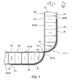
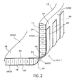
- the two interior panels for an aircraft 12, 14 are joined by the corner portions 24 of the two interior panels for an aircraft 12, 14 being brought together, and the connection pieces 26 of the two interior panels for an aircraft 12, 14 passing through the gaps 28 between the connection pieces 26 of the other interior panels for an aircraft 14, 12 to be joined, and being adhered to the external-side surface plates 22 of the other interior panels for an aircraft 14, 12 by an adhesive B (see FIG. 1 ).
- the two interior panels for an aircraft 12, 14 are joined so that the internal-side surface plates 20 intersect with each other at an angle of 90°.
- the internal-side surface plate 20 is provided with the flat surface portion 2002 that has an edge at the end portion thereof, and the connection pieces 26 are formed by the portions of the end portion of the flat surface portion 2002 protruding from the corner portion 24 and continuously protruding from the flat surface portion 2002.
- the external-side surface plate 22 has a flat surface portion 2202 that is parallel with the flat surface portion 2002 of the internal-side surface plate 20, and an end surface portion that protrudes from an end portion of the flat surface portion 2202 and is connected with the flat surface portion 2002 of the internal-side surface plate 20.
- the end surface portion is formed as a curved surface portion 30.
- the curved surface portion 30 is curved so as to gradually separate from the flat surface portion 2002 of the internal-side surface plate 20 as the curved surface portion 30 separates from the corner portion 24 and is connected with the end portion of the flat surface portion 2202 so as to gradually make the thickness of the interior panels for an aircraft 12, 14 larger.
- the connection pieces 26 of the two interior panels for an aircraft 12, 14 protrude with a uniform width.
- the connection pieces 26 of the two interior panels for an aircraft 12, 14 have a width in the direction orthogonal to the direction the connection pieces 26 protrude and a length in the direction the connection pieces 26 protrude.
- connection pieces 26 protrude with a uniform width
- the connection pieces 26 adjacent to each other are provided with the gap 28 therebetween, the gap 28 having the same dimension as the above-described width.
- the connection pieces 26 of the two interior panels for an aircraft 12, 14 pass through the gaps 28 between the connection pieces 26 of the other interior panels for an aircraft 14, 12 to be joined, and are attached by the adhesive B to the curved surface portion 30 and the flat surface portion 2202 of the external-side surface plate 22, of the other interior panels for an aircraft 14, 12.
- a base portion 2602 of the connection pieces 26 protruding from the corner portion 24 does not have any bent portion, and the connection pieces 26 extend continuously from the flat surface portion 2002 of the internal-side surface plate 20.
- a force in a direction Y1 acts on the one interior panel for an aircraft 12, in other words, when a force, in the direction toward a section at which the corner portions 24 of the two interior panels for an aircraft 12, 14 are brought together, acts in the direction along the surface of the one interior panel for an aircraft 12, portions of the connection pieces 26, which are attached to the curved surface portion 30 of the other interior panel for an aircraft 14, receive a compression force, so that this force is received.
- a force in a direction Y2 acts on the one interior panel for an aircraft 12, in other words, when a force, in the direction separating from the section at which the corner portions 24 of the two interior panels for an aircraft 12, 14 are brought together, acts in the direction along the surface of the one interior panel for an aircraft 12, the portions of the connection pieces 26, which are attached to the curved surface portion 30 of the other interior panel for an aircraft 14, receive a tensile force, so that this force is received. Furthermore, when a force in the direction orthogonal to the paper surface of FIG.
- connection pieces 26 which are attached to the curved surface portion 30 of the two interior panels for an aircraft 12, 14 receive a shearing force, so that this force is received.
- the internal-side surface plates 20 of the two interior panels for an aircraft 12, 14 are provided with the plurality of connection pieces 26, and the two interior panels for an aircraft 12, 14 can be joined by a simple structure in which the connection pieces 26 are adhered to the other interior panels for an aircraft 14, 12 to be joined.
- the conventionally used metal reinforcing frame, metal bolts, and metal insert nuts can be omitted, and this becomes advantageous in terms of realizing reduction in weight of the joining structure 10-1 for the two interior panels for an aircraft 12, 14.
- the number of parts can be reduced and the assembly becomes easy.
- FIGS. 5 to 8 a second embodiment will be described with reference to FIGS. 5 to 8 . Note that when the following embodiments are described below, the same reference numbers will be assigned to the same sections and components as those of the first embodiment, and descriptions for those sections and components will be omitted.
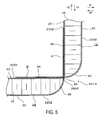
- the two interior panels for an aircraft 12, 14 are joined by a joining structure 10-2 of the second embodiment, as illustrated in FIG. 5 and FIG. 6 .
- connection pieces 26 of the two interior panels for an aircraft 12, 14 are provided on the external-side surface plates 22 and also in that the connection pieces 26 are adhered to sections of the internal-side surface plates 20 of the other interior panels for an aircraft 14, 12 to be joined.
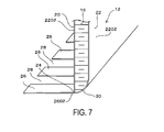
- the plurality of strip-shaped connection pieces 26 are provided, the connection pieces 26 being formed across the entire length of the corner portions 24 of the two interior panels for an aircraft 12, 14 by portions of the end portion of the external-side surface plate 22 protruding from the corner portions 24, in other words, formed by portions of an end portion of the curved surface portion 30 continuously protruding from the curved surface portion 30, with the gaps 28 between the strip-shaped connection pieces 26 in the direction the corner portions 24 extend.
- the two interior panels for an aircraft 12, 14 are joined by the corner portions 24 of the two interior panels for an aircraft 12, 14 being brought together, and the connection pieces 26 of the two interior panels for an aircraft 12, 14 passing through the gaps 28 between the connection pieces 26 of the other interior panels for an aircraft 14, 12 to be joined, and being attached to the flat surface portion 2002 of the internal-side surface plate 20 of the other interior panels for an aircraft 14, 12 by the adhesive B.
- the curved surface portion 30 of the other interior panel for an aircraft 14 receives a tensile force, so that this force is received. Furthermore, when the force in the direction orthogonal to the paper surface of FIG. 1 acts on the one interior panel for an aircraft 12, the connection pieces 26, which are attached to the flat surface portions 2002 of the two interior panels for an aircraft 12, 14, receive a shearing force, so that this force is absorbed.
- the conventionally used metal reinforcing frame, metal bolts, and metal insert nuts can be omitted, and this becomes advantageous in terms of realizing reduction in weight of the joining structure 10-2. Furthermore, as there is no need to reinforce the sections of the panels in which the insert nuts are embedded, as done conventionally and only the operation for adhering the connection pieces 26 is required, the number of parts can be reduced and the assembly becomes easy. This is also advantageous in terms of realizing cost reduction.
- the two interior panels for an aircraft 12, 14 are joined by a joining structure 10-3 of the third embodiment, as illustrated in FIG. 9 .
- a shape of the end portions of the interior panels for an aircraft 12, 14 is different from those of the first and second embodiments.
- the external-side surface plate 22 has the flat surface portion 2202 that is parallel with the flat surface portion 2002 of the internal-side surface plate 20 and the end surface portion that protrudes from the end portion of the flat surface portion 2202 and connects with the flat surface portion 2002 of the internal-side surface plate 20.
- This end surface portion is provided with a first end surface portion 32, which is formed by a flat surface that orthogonally intersects with the flat surface portion 2002 of the internal-side surface plate 20 at the corner portion 24, and a second end surface portion 34, which is connected with the first end surface portion 32 at an obtuse angle and is formed by a flat surface that connects with the flat surface portion 2202 of the external-side surface plate 22.
- the first end surface portion 32 and the second end surface portion 34 are connected via a curved portion 32A, and the second end surface portion 34 and the flat surface portion 2202 are connected via a curved portion 34A.
- connection pieces 26 are formed by the portions of the end portion of the flat surface portion 2002 of the internal-side surface plate 20 protruding from the corner portion 24.
- connection pieces 26 protruding from the corner portion 24 does not have any bent portion, and the connection pieces 26 extend continuously from the flat surface portion 2002 of the internal-side surface plate 20.
- connection pieces 26 do not have any bent portions, thereby preventing a reduction in strength of the connection pieces 26 caused by the bent portions.
- the two interior panels for an aircraft 12, 14 are joined by a joining structure 10-4 of the fourth embodiment, as illustrated in FIG. 10 .
- the fourth embodiment is different from the third embodiment in that the connection pieces 26 are provided on the external-side surface plate 22.
- connection pieces 26 are formed by portions of the external-side surface plate 22, namely, portions of the end portion of the first end surface portion 32 protruding from the corner portion 24.
- connection pieces 26 of the two interior panels for an aircraft 12, 14 pass through the gaps 28 between the connection pieces 26 of the other interior panels for an aircraft 14, 12 to be joined and are attached to the flat surface portion 2002 of the internal-side surface plate 20 of the other interior panels for an aircraft 14, 12.
- connection pieces 26 protruding from the corner portion 24 does not have any bent portion, and the connection pieces 26 extend continuously from the first end surface portion 32.
- the number of the second end surface portion 34 which connects the first end surface portion 32 with the flat surface portion 2202 of the external-side surface plate 22
- the number of the second end surface portion 34 may be two or more, and the end portions of the interior panels for an aircraft 12, 14 may have a polygonal cross-section, for example.
- the two interior panels for an aircraft 12, 14 are joined by a joining structure 10-5 of the fifth embodiment, as illustrated in FIG. 11 .
- the shape of the end portions of the interior panels for an aircraft 12, 14 is different from those of the first to fourth embodiments.
- the external-side surface plate 22 has the flat surface portion 2202 that is parallel with the flat surface portion 2002 of the internal-side surface plate 20 and the end surface portion that protrudes from the end portion of the flat surface portion 2202 and connects with the flat surface portion 2002 of the internal-side surface plate 20.
- the end surface portion is provided as an end surface portion 38 that is formed by a flat surface which orthogonally intersects with the flat surface portion 2002 of the internal-side surface plate 20 at the corner portion 24 and is orthogonally connected with the flat surface portion 2202 of the external-side surface plate 22.
- the end surface portion 38 and the flat surface portion 2202 are connected via a curved portion 38A.
- connection pieces 26 are formed by the portions of the end portion of the flat surface portion 2002 of the internal-side surface plate 20 protruding from the corner portion 24.
- connection pieces 26 of the two interior panels for an aircraft 12, 14 pass through the gaps 28 between the connection pieces 26 of the other interior panels for an aircraft 14, 12 to be joined and are attached to the end surface portion 38 and the flat surface portion 2202 of the external-side surface plate 22, of the other interior panels for an aircraft 14, 12.
- connection pieces 26 protruding from the corner portion 24 does not have any bent portion, and the connection pieces 26 extend continuously from the flat surface portion 2002 of the internal-side surface plate 20.
- connection pieces 26 do not have any bent portions, thereby preventing a reduction in strength of the connection pieces 26 caused by the bent portions.
- the two interior panels for an aircraft 12, 14 are joined by a joining structure 10-6 of the sixth embodiment, as illustrated in FIG. 12 .
- the sixth embodiment is different from the fifth embodiment in that the connection pieces 26 are provided on the external-side surface plate 22.
- connection pieces 26 are formed by the portions of the external-side surface plate 22, namely, portions of an end portion of the end surface portion 38 protruding from the corner portion 24.
- connection pieces 26 of the two interior panels for an aircraft 12, 14 pass through the gaps 28 between the connection pieces 26 of the other interior panels for an aircraft 14, 12 to be joined and are attached to the flat surface portion 2002 of the internal-side surface plate 20 of the other interior panels for an aircraft 14, 12.
- connection pieces 26 protruding from the corner portion 24 does not have any bent portion, and the connection pieces 26 extend continuously from the end surface portion 38.
- the two interior panels for an aircraft 12, 14 are joined by a joining structure 10-7 of the seventh embodiment, as illustrated in FIG. 13 .
- a material of the core 16 that forms the end portion of the interior panels for an aircraft 12, 14 is different from those of the first to sixth embodiments.
- cores 1602 which form the end portions at which the corner portions 24 of the interior panels for an aircraft 12, 14 are provided, are formed of a material having higher compression strength than that of the cores 16 forming the remaining portion of the interior panels for an aircraft 12, 14.
- Various conventionally known materials, such as urethane resin, can be used as such material having high compression strength.
- the seventh embodiment when a large load is applied in the direction Y1 or Y2, there is an advantage in which the load can be also received by the end portion of the interior panels for an aircraft 12, 14.
- the two interior panels for an aircraft 12, 14 are joined by a joining structure 10-8 of the eighth embodiment, as illustrated in FIG. 14 .
- the eighth embodiment is different from the first to seventh embodiments in that a reinforcing member 40 is provided.
- the two interior panels for an aircraft 12, 14 are joined by the joining structure 10-1 of the first embodiment so as to intersect at an angle of 90°, and the reinforcing member 40, having an L-shaped cross-section and formed by two flanges 4002, 4002 being orthogonal, is arranged in a section at which the two interior panels for an aircraft 12, 14 orthogonally intersect.
- Fiber reinforced plastic, reinforced plastic, a lightweight metal plate formed of aluminum alloy, or the like, is used as the reinforcing member 40.
- the two respective flanges 4002 are attached to the internal-side surface plates 20 of the two interior panels for an aircraft 12, 14 by the adhesive B.
- the reinforcing member 40 may extend over the entire length of the corner portion 24, or a plurality of reinforcing members 40 may be provided at intervals in the direction the corner portion 24 extends.
Landscapes
- Engineering & Computer Science (AREA)
- Aviation & Aerospace Engineering (AREA)
- Mechanical Engineering (AREA)
- Remote Sensing (AREA)
- Standing Axle, Rod, Or Tube Structures Coupled By Welding, Adhesion, Or Deposition (AREA)
- Connection Of Plates (AREA)
Abstract
Description
- The present invention relates to a joining structure for an interior panel for an aircraft, the interior panel being installed inside an aircraft.
- A lavatory unit, a galley, a hand baggage storage shelf, a divider, and the like are arranged inside an aircraft. For example, with respect to the lavatory unit, a housing, which partitions the lavatory, is formed by a plurality of interior panels for an aircraft being joined together. With respect to the galley and the hand baggage storage space, a housing, which partitions the goods storage space, is formed by the plurality of interior panels for an aircraft being joined together, and the divider is formed by the plurality of interior panels for an aircraft being joined together, the plurality of interior panels forming partition plates.
These interior panels for an aircraft, which are used inside an aircraft, are formed by lightweight and rigid panels from the perspective of realizing reduction in weight.
In many cases, such an interior panel is formed by a honeycomb structured core formed of synthetic resin and by surface plates formed of fiber reinforced plastic, reinforced plastic, or metal being adhered to both sides of the core.
Then, when the interior panels for an aircraft are joined together, a metal reinforcing frame having an L-shaped cross-section is arranged at an intersection portion at which the two interior panels for an aircraft intersect, metal insert nuts are embedded in end portions of the interior panels for an aircraft, and metal bolts, which are inserted through attachment holes of the reinforcing frame, are screwed into the insert nuts. -
- Patent Document 1:
- Japanese Unexamined Patent Application Publication No.
2009-73311A - Patent Document 2:
- Japanese Unexamined Patent Application Publication No.
2012-171568A - However, with a conventional joining structure as described above, as metal reinforcing frames, metal bolts, and metal insert nuts are used, there has been a disadvantage that the weight of the joining structure increases.
- Furthermore, as it is necessary to reinforce sections of the interior panel for an aircraft in which the insert nuts are embedded, the number of parts increases and assembly has become more time-consuming, and there is a disadvantage in terms of realizing cost reduction.
- The present invention has been devised in light of the above-described circumstances, and an object of the present invention is to provide a joining structure for an interior panel for an aircraft that is advantageous in terms of realizing reduction in weight of and cost reduction of the joining structure.
- In order to achieve the above-described object, the present invention provides a joining structure for an interior panel for an aircraft including: two interior panels for an aircraft including a plate-shaped core having a uniform thickness and a first surface plate and a second surface plate attached to both sides of the core, the two interior panels for an aircraft being joined so that the first surface plates intersect with each other and the second surface plates intersect with each other. In such a joining structure, the first surface plate and the second surface plate have a flat surface portion, the flat surface portions being parallel with each other; the second surface plate has an end surface portion that protrudes from an end portion of the flat surface portion and is connected with an end portion of the flat surface portion of the first surface plate as well as the flat surface portion; a corner portion is provided by the end portion of the flat surface portion of the first surface plate and an end portion of the end surface portion of the second surface plate being attached on the first surface plate, the corner portion extending in a direction the end portions extend; a plurality of strip-shaped connection pieces are provided, the connection pieces being formed across an entire length of the corner portions of the two interior panels for an aircraft by portions of the end portion of the flat surface portion of the first surface plate protruding from the corner portion and continuously protruding from the flat surface portion of the first surface plate or by portions of the end portion of the end surface portion of the second surface plate continuously protruding from the end surface portion, and the connection pieces having gaps therebetween in a direction the corner portion extends; and the two interior panels for an aircraft are joined by the corner portions of the two interior panels for an aircraft being brought together, and the connection pieces of the two interior panels for an aircraft passing through the gaps between the connection pieces of the other interior panels for an aircraft to be joined, and being adhered to one of the second surface plate and the first surface plate of the other interior panels for an aircraft.
- In the present invention, two interior panels for an aircraft can be joined using a simple structure in which the two interior panels for an aircraft are each provided with a plurality of connection pieces and the connection pieces are adhered to the other interior panel to be joined.
- Therefore, the conventionally used metal reinforcing frame, metal bolts, and metal insert nuts can be omitted, and this becomes advantageous in terms of realizing reduction in weight of the joining structure.
- Furthermore, as there is no need to reinforce the sections of the panels in which the insert nuts are embedded, as done conventionally and only an operation for adhering the connection pieces is required, the number of parts can be reduced and the assembly becomes easy. This is also advantageous in terms of realizing cost reduction.
-
- FIG. 1
- is a cross-sectional view illustrating a section in which two interior panels for an aircraft are joined by a joining structure according to a first embodiment.
- FIG. 2
- is a perspective cross-sectional view illustrating the section in which the two interior panels for an aircraft are joined.
- FIG. 3
- is a perspective cross-sectional view illustrating an end portion of one of the interior panels for an aircraft.
- FIG. 4
- is a perspective cross-sectional view illustrating an end portion of the other interior panel for an aircraft.
- FIG. 5
- is a cross-sectional view illustrating a section in which the two interior panels for an aircraft are joined by a joining structure according to a second embodiment.
- FIG. 6
- is a perspective cross-sectional view illustrating the section in which the two interior panels for an aircraft are joined.
- FIG. 7
- is a perspective cross-sectional view illustrating an end portion of one of the interior panels for an aircraft.
- FIG. 8
- is a perspective cross-sectional view illustrating an end portion of the other interior panel for an aircraft.
- FIG. 9
- is a cross-sectional view illustrating a section in which the two interior panels for an aircraft are joined by a joining structure according to a third embodiment.
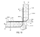
- FIG. 10
- is a cross-sectional view illustrating a section in which the two interior panels for an aircraft are joined by a joining structure according to a fourth embodiment.
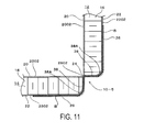
- FIG. 11
- is a cross-sectional view illustrating a section in which the two interior panels for an aircraft are joined by a joining structure according to a fifth embodiment.
- FIG. 12
- is a cross-sectional view illustrating a section in which the two interior panels for an aircraft are joined by a joining structure according to a sixth embodiment.
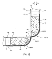
- FIG. 13
- is a cross-sectional view illustrating a section in which the two interior panels for an aircraft are joined by a joining structure according to a seventh embodiment.
- FIG. 14
- is a cross-sectional view illustrating a section in which the two interior panels for an aircraft are joined by a joining structure according to an eighth embodiment.
- Next, embodiments of the present invention will be described with reference to the drawings.
- First, a first embodiment will be described with reference to
FIGS. 1 to 4 . - Two interior panels for an
aircraft FIG. 1 andFIG. 2 . - The interior panels for an
aircraft - Each of the interior panels for an
aircraft core 16 and an internal-side surface plate 20 and an external-side surface plate 22 that are attached to both sides of thecore 16 by an adhesive, from the perspective of realizing reduction in weight while maintaining rigidity. When the interior panels for anaircraft side surface plate 20 is used so as to be positioned inside the lavatory and the external-side surface plate 22 is used so as to be positioned outside the lavatory. Depending on the usage, the same surface plate is used for the internal-side surface plate 20 and the external-side surface plate 22. - Note that in all embodiments including the present embodiment, the internal-
side surface plate 20 corresponds to a first surface plate and the external-side surface plate 22 corresponds to a second surface plate, and the two interior panels for an aircraft are joined so that the internal-side surface plates 20 intersect with each other and the external-side surface plates 22 intersect with each other. - As a material of the
core 16, a honeycomb structured material formed of synthetic resin material, aluminum alloy, or the like is used, for example. Thecore 16 has a plate shape with a uniform thickness. - Furthermore, as the internal-
side surface plate 20 and the external-side surface plate 22, for example a fiber reinforced plastic, a reinforced plastic, a lightweight metal plate formed of aluminum alloy, or the like is used. The internal-side surface plate 20 and the external-side surface plate 22 each have a uniform thickness. - Provided at the end portion (one side) of each of the two interior panels for an
aircraft corner portion 24 formed by an edge of an end portion of the internal-side surface plate 20 and an edge of an end portion of the external-side surface plate 22 being attached on the internal-side surface plate 20, thecorner portion 24 extending in the direction these edges extend.
At thecorner portion 24, a plurality of strip-shapedconnection pieces 26 are provided, theconnection pieces 26 being formed across the entire length of thecorner portion 24 by portions of an end portion of aflat surface portion 2002 of the internal-side surface plate 20 protruding from thecorner portion 24, withgaps 28 between the strip-shapedconnection pieces 26 in the direction thecorner portion 24 extends.
Then, the two interior panels for anaircraft corner portions 24 of the two interior panels for anaircraft connection pieces 26 of the two interior panels for anaircraft gaps 28 between theconnection pieces 26 of the other interior panels for anaircraft side surface plates 22 of the other interior panels for anaircraft FIG. 1 ).
In the present embodiment, the two interior panels for anaircraft side surface plates 20 intersect with each other at an angle of 90°. - Describing in more detail, the internal-
side surface plate 20 is provided with theflat surface portion 2002 that has an edge at the end portion thereof, and theconnection pieces 26 are formed by the portions of the end portion of theflat surface portion 2002 protruding from thecorner portion 24 and continuously protruding from theflat surface portion 2002.
The external-side surface plate 22 has aflat surface portion 2202 that is parallel with theflat surface portion 2002 of the internal-side surface plate 20, and an end surface portion that protrudes from an end portion of theflat surface portion 2202 and is connected with theflat surface portion 2002 of the internal-side surface plate 20.
The end surface portion is formed as acurved surface portion 30. Thecurved surface portion 30 is curved so as to gradually separate from theflat surface portion 2002 of the internal-side surface plate 20 as thecurved surface portion 30 separates from thecorner portion 24 and is connected with the end portion of theflat surface portion 2202 so as to gradually make the thickness of the interior panels for anaircraft
Theconnection pieces 26 of the two interior panels for anaircraft connection pieces 26 of the two interior panels for anaircraft connection pieces 26 protrude and a length in the direction theconnection pieces 26 protrude. When it is described that theconnection pieces 26 protrude with a uniform width, this means that the width of theconnection pieces 26 of the two interior panels for anaircraft
Furthermore, theconnection pieces 26 adjacent to each other are provided with thegap 28 therebetween, thegap 28 having the same dimension as the above-described width.
Theconnection pieces 26 of the two interior panels for anaircraft gaps 28 between theconnection pieces 26 of the other interior panels for anaircraft curved surface portion 30 and theflat surface portion 2202 of the external-side surface plate 22, of the other interior panels for anaircraft
Abase portion 2602 of theconnection pieces 26 protruding from thecorner portion 24 does not have any bent portion, and theconnection pieces 26 extend continuously from theflat surface portion 2002 of the internal-side surface plate 20. - As illustrated in
FIG. 1 , when a force in a direction X1 or a force in a direction X2 acts on the one interior panel for anaircraft 12, in other words, when a force in the orthogonal direction with respect to a surface of the one interior panel for anaircraft 12 acts thereon, a bending moment thus generated is released by thebase portions 2602 of theconnection pieces 26 of the two interior panels for anaircraft
More specifically, when the force in the direction X1 or X2 acts on the one interior panel for anaircraft 12, the joining structure 10-1 of the present embodiment functions as if it were a pin connection.
Furthermore, when a force in a direction Y1 acts on the one interior panel for anaircraft 12, in other words, when a force, in the direction toward a section at which thecorner portions 24 of the two interior panels for anaircraft aircraft 12, portions of theconnection pieces 26, which are attached to thecurved surface portion 30 of the other interior panel for anaircraft 14, receive a compression force, so that this force is received.
Furthermore, when a force in a direction Y2 acts on the one interior panel for anaircraft 12, in other words, when a force, in the direction separating from the section at which thecorner portions 24 of the two interior panels for anaircraft aircraft 12, the portions of theconnection pieces 26, which are attached to thecurved surface portion 30 of the other interior panel for anaircraft 14, receive a tensile force, so that this force is received.
Furthermore, when a force in the direction orthogonal to the paper surface ofFIG. 1 acts on the one interior panel for anaircraft 12, in other words, when a force, in the direction parallel with the direction the brought-together corner portions 24 of the two interior panels for anaircraft aircraft 12, theconnection pieces 26 which are attached to thecurved surface portion 30 of the two interior panels for anaircraft - According to the present embodiment, the internal-
side surface plates 20 of the two interior panels for anaircraft connection pieces 26, and the two interior panels for anaircraft connection pieces 26 are adhered to the other interior panels for anaircraft
Thus, the conventionally used metal reinforcing frame, metal bolts, and metal insert nuts can be omitted, and this becomes advantageous in terms of realizing reduction in weight of the joining structure 10-1 for the two interior panels for anaircraft
Furthermore, as there is no need to reinforce sections of the panels in which the insert nuts are embedded, as done conventionally, and only an operation for adhering theconnection pieces 26 is required, the number of parts can be reduced and the assembly becomes easy. This is also advantageous in terms of realizing cost reduction.
Furthermore, as the metal insert nuts can be omitted, sections of the core 16 that are conventionally discarded so as to have the insert nuts embedded are eliminated as well. As the discarded core is eliminated, this is also advantageous in terms of using thecore 16 efficiently. - Next, a second embodiment will be described with reference to
FIGS. 5 to 8 . Note that when the following embodiments are described below, the same reference numbers will be assigned to the same sections and components as those of the first embodiment, and descriptions for those sections and components will be omitted. - The two interior panels for an
aircraft FIG. 5 andFIG. 6 . - The second embodiment is different from the first embodiment in that the
connection pieces 26 of the two interior panels for anaircraft side surface plates 22 and also in that theconnection pieces 26 are adhered to sections of the internal-side surface plates 20 of the other interior panels for anaircraft - More specifically, in the second embodiment, the plurality of strip-shaped
connection pieces 26 are provided, theconnection pieces 26 being formed across the entire length of thecorner portions 24 of the two interior panels for anaircraft side surface plate 22 protruding from thecorner portions 24, in other words, formed by portions of an end portion of thecurved surface portion 30 continuously protruding from thecurved surface portion 30, with thegaps 28 between the strip-shapedconnection pieces 26 in the direction thecorner portions 24 extend. - Then, the two interior panels for an
aircraft corner portions 24 of the two interior panels for anaircraft connection pieces 26 of the two interior panels for anaircraft gaps 28 between theconnection pieces 26 of the other interior panels for anaircraft flat surface portion 2002 of the internal-side surface plate 20 of the other interior panels for anaircraft - The
base portion 2602 of theconnection pieces 26 protruding from thecorner portion 24 does not have any bent portion, and theconnection pieces 26 extend continuously from thecurved surface portion 30. - The same effects as the first embodiment are also exhibited by the second embodiment.
- More specifically, as illustrated in
FIG. 5 , when the force in the direction X1 or the force in the direction X2 acts on the one interior panel for anaircraft 12, the bending moment thus generated is released by thebase portions 2602 of theconnection pieces 26 of the two interior panels for anaircraft
More specifically, when the force in the direction X1 or X2 acts on the one interior panel for anaircraft 12, the joining structure 10-2 of the present embodiment functions as if it were a pin connection.
Furthermore, when the force in the direction Y1 acts on the one interior panel for anaircraft 12, thecurved surface portion 30 of the other interior panel for anaircraft 14 receives a compression force, so that this force is received. Furthermore, when the force in the Y2 direction acts on the one interior panel for anaircraft 12, thecurved surface portion 30 of the other interior panel for anaircraft 14 receives a tensile force, so that this force is received.
Furthermore, when the force in the direction orthogonal to the paper surface ofFIG. 1 acts on the one interior panel for anaircraft 12, theconnection pieces 26, which are attached to theflat surface portions 2002 of the two interior panels for anaircraft - Thus, according to the second embodiment also, the conventionally used metal reinforcing frame, metal bolts, and metal insert nuts can be omitted, and this becomes advantageous in terms of realizing reduction in weight of the joining structure 10-2. Furthermore, as there is no need to reinforce the sections of the panels in which the insert nuts are embedded, as done conventionally and only the operation for adhering the
connection pieces 26 is required, the number of parts can be reduced and the assembly becomes easy. This is also advantageous in terms of realizing cost reduction. - Next, a third embodiment will be described with reference to
FIG. 9 . - The two interior panels for an
aircraft FIG. 9 . - In the third embodiment, a shape of the end portions of the interior panels for an
aircraft - In the third embodiment, the external-
side surface plate 22 has theflat surface portion 2202 that is parallel with theflat surface portion 2002 of the internal-side surface plate 20 and the end surface portion that protrudes from the end portion of theflat surface portion 2202 and connects with theflat surface portion 2002 of the internal-side surface plate 20. This end surface portion is provided with a firstend surface portion 32, which is formed by a flat surface that orthogonally intersects with theflat surface portion 2002 of the internal-side surface plate 20 at thecorner portion 24, and a secondend surface portion 34, which is connected with the firstend surface portion 32 at an obtuse angle and is formed by a flat surface that connects with theflat surface portion 2202 of the external-side surface plate 22. - The first
end surface portion 32 and the secondend surface portion 34 are connected via acurved portion 32A, and the secondend surface portion 34 and theflat surface portion 2202 are connected via acurved portion 34A. - The
connection pieces 26 are formed by the portions of the end portion of theflat surface portion 2002 of the internal-side surface plate 20 protruding from thecorner portion 24. - The
connection pieces 26 of the two interior panels for anaircraft gaps 28 between theconnection pieces 26 of the other interior panels for anaircraft end surface portion 32, the secondend surface portion 34, and theflat surface portion 2202 of the external-side surface plate 22, of the other interior panels for anaircraft - The
base portion 2602 of theconnection pieces 26 protruding from thecorner portion 24 does not have any bent portion, and theconnection pieces 26 extend continuously from theflat surface portion 2002 of the internal-side surface plate 20. - As the
curved portions aircraft connection pieces 26 do not have any bent portions, thereby preventing a reduction in strength of theconnection pieces 26 caused by the bent portions. - The same effects as the first embodiment are also exhibited by the third embodiment.
- Next, a fourth embodiment will be described with reference to
FIG. 10 . - The two interior panels for an
aircraft FIG. 10 . - The fourth embodiment is different from the third embodiment in that the
connection pieces 26 are provided on the external-side surface plate 22. - More specifically, the
connection pieces 26 are formed by portions of the external-side surface plate 22, namely, portions of the end portion of the firstend surface portion 32 protruding from thecorner portion 24. - The
connection pieces 26 of the two interior panels for anaircraft gaps 28 between theconnection pieces 26 of the other interior panels for anaircraft flat surface portion 2002 of the internal-side surface plate 20 of the other interior panels for anaircraft - The
base portion 2602 of theconnection pieces 26 protruding from thecorner portion 24 does not have any bent portion, and theconnection pieces 26 extend continuously from the firstend surface portion 32. - The same effects as the second embodiment are also exhibited by the fourth embodiment.
- Note that, although cases have been described in which the number of the second
end surface portion 34, which connects the firstend surface portion 32 with theflat surface portion 2202 of the external-side surface plate 22, is one in the third and fourth embodiments, the number of the secondend surface portion 34 may be two or more, and the end portions of the interior panels for anaircraft - Next, a fifth embodiment will be described with reference to
FIG. 11 . - The two interior panels for an
aircraft FIG. 11 . - In the fifth embodiment, the shape of the end portions of the interior panels for an
aircraft - In the fifth embodiment, the external-
side surface plate 22 has theflat surface portion 2202 that is parallel with theflat surface portion 2002 of the internal-side surface plate 20 and the end surface portion that protrudes from the end portion of theflat surface portion 2202 and connects with theflat surface portion 2002 of the internal-side surface plate 20. The end surface portion is provided as anend surface portion 38 that is formed by a flat surface which orthogonally intersects with theflat surface portion 2002 of the internal-side surface plate 20 at thecorner portion 24 and is orthogonally connected with theflat surface portion 2202 of the external-side surface plate 22. - The
end surface portion 38 and theflat surface portion 2202 are connected via acurved portion 38A. - The
connection pieces 26 are formed by the portions of the end portion of theflat surface portion 2002 of the internal-side surface plate 20 protruding from thecorner portion 24. - The
connection pieces 26 of the two interior panels for anaircraft gaps 28 between theconnection pieces 26 of the other interior panels for anaircraft end surface portion 38 and theflat surface portion 2202 of the external-side surface plate 22, of the other interior panels for anaircraft - The
base portion 2602 of theconnection pieces 26 protruding from thecorner portion 24 does not have any bent portion, and theconnection pieces 26 extend continuously from theflat surface portion 2002 of the internal-side surface plate 20. - As the
curved portion 38A is provided on the end portion of the interior panels for anaircraft connection pieces 26 do not have any bent portions, thereby preventing a reduction in strength of theconnection pieces 26 caused by the bent portions. - The same effects as the first and third embodiments are also exhibited by the fifth embodiment.
- Next, a sixth embodiment will be described with reference to
FIG. 12 . - The two interior panels for an
aircraft FIG. 12 . - The sixth embodiment is different from the fifth embodiment in that the
connection pieces 26 are provided on the external-side surface plate 22. - More specifically, the
connection pieces 26 are formed by the portions of the external-side surface plate 22, namely, portions of an end portion of theend surface portion 38 protruding from thecorner portion 24. - The
connection pieces 26 of the two interior panels for anaircraft gaps 28 between theconnection pieces 26 of the other interior panels for anaircraft flat surface portion 2002 of the internal-side surface plate 20 of the other interior panels for anaircraft - The
base portion 2602 of theconnection pieces 26 protruding from thecorner portion 24 does not have any bent portion, and theconnection pieces 26 extend continuously from theend surface portion 38. - The same effects as the second and fourth embodiments are also exhibited by the sixth embodiment.
- Next, a seventh embodiment will be described with reference to
FIG. 13 . - The two interior panels for an
aircraft FIG. 13 . - In the seventh embodiment, a material of the core 16 that forms the end portion of the interior panels for an
aircraft - Although the two interior panels for an
aircraft FIG. 13 ,cores 1602, which form the end portions at which thecorner portions 24 of the interior panels for anaircraft cores 16 forming the remaining portion of the interior panels for anaircraft - According to the seventh embodiment, when a large load is applied in the direction Y1 or Y2, there is an advantage in which the load can be also received by the end portion of the interior panels for an
aircraft - Next, an eighth embodiment will be described with reference to
FIG. 14 . - The two interior panels for an
aircraft FIG. 14 . - The eighth embodiment is different from the first to seventh embodiments in that a reinforcing
member 40 is provided. - In an example illustrated in
FIG. 14 , the two interior panels for anaircraft member 40, having an L-shaped cross-section and formed by twoflanges aircraft - Fiber reinforced plastic, reinforced plastic, a lightweight metal plate formed of aluminum alloy, or the like, is used as the reinforcing
member 40. - The two
respective flanges 4002 are attached to the internal-side surface plates 20 of the two interior panels for anaircraft - Note that the reinforcing
member 40 may extend over the entire length of thecorner portion 24, or a plurality of reinforcingmembers 40 may be provided at intervals in the direction thecorner portion 24 extends. - According to the eighth embodiment, when a large load is applied in the direction X1 or X2, there is an advantage in which the load can be received by the reinforcing
member 40. - Note that although, in the above-described embodiments, cases have been described in which the two interior panels for an
aircraft aircraft -
- 10-1 to 10-7 Joining structure
- 12, 14 Interior panels for an aircraft
- 16 Core
- 20 Internal-side surface plate
- 2002 Flat surface portion
- 22 External-side surface plate
- 2202 Flat surface portion
- 24 Corner portion
- 26 Connection piece
- 28 Gap
- 30 Curved surface portion
- 32 First end surface portion
- 34 Second end surface portion
- 38 End surface portion
- 40 Reinforcing member
Claims (8)
- A joining structure for an interior panel for an aircraft, comprising:two interior panels for an aircraft each including a plate-shaped core having a uniform thickness anda first surface plate and a second surface plate attached to both sides of the core, the two interior panels for an aircraft being joined so that the first surface plates intersect with each other and the second surface plates intersect with each other; whereinthe first surface plate and the second surface plate have a flat surface portion, the flat surface portions being parallel with each other;
the second surface plate has an end surface portion that protrudes from an end portion of the flat surface portion and is connected with an end portion of the flat surface portion of the first surface plate as well as the flat surface portion;
a corner portion is provided by the end portion of the flat surface portion of the first surface plate and an end portion of the end surface portion of the second surface plate being attached, the corner portion extending in a direction the end portions extend;
a plurality of strip-shaped connection pieces are provided, the connection pieces being formed across an entire length of the corner portions of the two interior panels for an aircraft by portions of the end portion of the flat surface portion of the first surface plate protruding from the corner portion and continuously protruding from the flat surface portion of the first surface plate or by portions of the end portion of the end surface portion of the second surface plate continuously protruding from the end surface portion, and the connection pieces having gaps therebetween in a direction the corner portion extends; and
the two interior panels for an aircraft are joined by the corner portions of the two interior panels for an aircraft being brought together, and the connection pieces of the two interior panels for an aircraft passing through the gaps between the connection pieces of the other interior panels for an aircraft to be joined, and being adhered to one of the second surface plate and the first surface plate of the other interior panels for an aircraft. - The joining structure for an interior panel for an aircraft according to claim 1, wherein
the connection pieces of the two interior panels for an aircraft to be joined are formed having a uniform width. - The joining structure for an interior panel for an aircraft according to claim 1 or 2, wherein
the two interior panels for an aircraft to be joined are joined so that the first surface plates intersect with each other at an angle of 90°. - The joining structure for an interior panel for an aircraft according to any one of claims 1 to 3, wherein
the core forming the end portion, at which the corner portion of the interior panel for an aircraft is provided, is formed of a material having a higher compression strength than that of the core forming the remaining portion of the interior panel for an aircraft. - The joining structure for an interior panel for an aircraft according to any one of claims 1 to 4, wherein
a reinforcing member having two flanges is arranged in a section at which the two interior panels for an aircraft intersect, and
the two respective flanges are attached to the first surface plates of the two interior panels for an aircraft. - The joining structure for an interior panel for an aircraft according to any one of claims 1 to 5, wherein
the end surface portion is formed as a curved surface portion, the curved surface portion being curved so as to gradually separate from the flat surface portion of the first surface plate as the curved surface portion separates from the corner portion and connected with the flat surface portion of the second surface plate. - The joining structure for an interior panel for an aircraft according to any one of claims 1 to 5, wherein
the end surface portion is provided with a first end surface portion formed by a flat surface intersecting with the flat surface portion of the first surface plate at the corner portion and with a second end surface portion formed by at least one of one flat surface and a plurality of flat surfaces that connect the first end surface portion with the flat surface portion of the second surface plate. - The joining structure for an interior panel for an aircraft according to any one of claims 1 to 5, wherein
the end surface portion is provided with a flat surface portion that orthogonally intersect with the flat surface portion of the first surface plate at the corner portion.
Applications Claiming Priority (2)
| Application Number | Priority Date | Filing Date | Title |
|---|---|---|---|
| JP2012276374A JP5811082B2 (en) | 2012-12-19 | 2012-12-19 | Connection structure for aircraft interior panels |
| PCT/JP2013/007426 WO2014097619A1 (en) | 2012-12-19 | 2013-12-18 | Joining structure for interior panel for aeroplane |
Publications (3)
| Publication Number | Publication Date |
|---|---|
| EP2921405A1 true EP2921405A1 (en) | 2015-09-23 |
| EP2921405A4 EP2921405A4 (en) | 2016-09-14 |
| EP2921405B1 EP2921405B1 (en) | 2018-08-08 |
Family
ID=50977980
Family Applications (1)
| Application Number | Title | Priority Date | Filing Date |
|---|---|---|---|
| EP13865424.9A Not-in-force EP2921405B1 (en) | 2012-12-19 | 2013-12-18 | Joining structure for interior panel for aeroplane |
Country Status (4)
| Country | Link |
|---|---|
| US (1) | US9440726B2 (en) |
| EP (1) | EP2921405B1 (en) |
| JP (1) | JP5811082B2 (en) |
| WO (1) | WO2014097619A1 (en) |
Families Citing this family (3)
| Publication number | Priority date | Publication date | Assignee | Title |
|---|---|---|---|---|
| US10392132B2 (en) * | 2016-07-29 | 2019-08-27 | The Boeing Company | Curved aircraft substructure repair systems and methods |
| EP4461637A1 (en) | 2023-05-12 | 2024-11-13 | Airbus Operations GmbH | A cover for a transition from a lining to a monument |
| CN117508620B (en) * | 2023-12-11 | 2026-04-10 | 中国航空工业集团公司西安飞机设计研究所 | Dislocation plug-in type interior trim mounting structure |
Family Cites Families (10)
| Publication number | Priority date | Publication date | Assignee | Title |
|---|---|---|---|---|
| US4671470A (en) * | 1985-07-15 | 1987-06-09 | Beech Aircraft Corporation | Method for fastening aircraft frame elements to sandwich skin panels covering same using woven fiber connectors |
| US5212003A (en) * | 1992-01-22 | 1993-05-18 | General Electric Co. | Low stress panel joints |
| FR2711744B1 (en) * | 1993-10-25 | 1996-01-12 | Serap Industries | Method of assembling several composite panels, in particular sandwich panels. |
| JPH09131788A (en) * | 1995-11-13 | 1997-05-20 | Jamco Corp | Honeycomb panel processing method |
| JPH09131817A (en) * | 1995-11-13 | 1997-05-20 | Jamco Corp | End face treatment method for honeycomb panel |
| GB9903161D0 (en) | 1999-02-13 | 1999-04-07 | Secr Defence Brit | eland The SEE Sharp Kabushiki Kaisha retary of State for Defence, The Method of joining sandwich panels |
| WO2002028709A1 (en) * | 2000-10-02 | 2002-04-11 | Bell Helicopter Textron Inc. | Composite skin panel opening edge and method for manufacture |
| JP2004179730A (en) * | 2002-11-25 | 2004-06-24 | Yokohama Rubber Co Ltd:The | Joining structure of layered body in which frequency selecting element used for radome is incorporated |
| JP2009073311A (en) * | 2007-09-20 | 2009-04-09 | Yokohama Rubber Co Ltd:The | Lavatory unit |
| JP5655625B2 (en) | 2011-02-24 | 2015-01-21 | 横浜ゴム株式会社 | Mounting structure of the insert nut to the panel |
-
2012
- 2012-12-19 JP JP2012276374A patent/JP5811082B2/en not_active Expired - Fee Related
-
2013
- 2013-12-18 EP EP13865424.9A patent/EP2921405B1/en not_active Not-in-force
- 2013-12-18 US US14/652,448 patent/US9440726B2/en not_active Expired - Fee Related
- 2013-12-18 WO PCT/JP2013/007426 patent/WO2014097619A1/en not_active Ceased
Also Published As
| Publication number | Publication date |
|---|---|
| US9440726B2 (en) | 2016-09-13 |
| JP2014118091A (en) | 2014-06-30 |
| EP2921405B1 (en) | 2018-08-08 |
| JP5811082B2 (en) | 2015-11-11 |
| EP2921405A4 (en) | 2016-09-14 |
| WO2014097619A1 (en) | 2014-06-26 |
| US20150329192A1 (en) | 2015-11-19 |
Similar Documents
| Publication | Publication Date | Title |
|---|---|---|
| CA2320016C (en) | Wall joint configuration | |
| EP2921405B1 (en) | Joining structure for interior panel for aeroplane | |
| US8540099B2 (en) | Container sidewall connector | |
| US10556686B2 (en) | Cabin monument for an aircraft | |
| EP3369679A1 (en) | Frame structure, method of assembling | |
| EP2821340A1 (en) | Composite material structural body, aircraft wing and aircraft body provided with same, and method of manufacturing composite material structural body | |
| SE535297C2 (en) | Carrying frame | |
| EP3339677A1 (en) | Energy absorbing structure for attenuating the energy transmitted from an energy source | |
| JP2019503159A (en) | Solar cell assembly and solar cell module | |
| EP2942269A1 (en) | Method for manufacturing a load bearing structure and such a load bearing structure | |
| EP0396306B1 (en) | Sandwich panel core structure | |
| WO2017070014A1 (en) | Modular aviation equipment rack | |
| RU2661411C2 (en) | Symmetrical wings nervure with crossed cross-sections adjusted by central plane | |
| CN110406657B (en) | Civil aircraft wing upper wall plate root connecting corner box, connecting structure and wing | |
| EP2589634A2 (en) | Tape structure and solar module using the same | |
| US20120234842A1 (en) | Container Sidewall Connector | |
| EP2896498A1 (en) | Sandwich-structural composite apparatus with core joining and splicing method for retention of structural and acoustic capability | |
| KR20100010846U (en) | Frame structure for a exhibition booth | |
| US20190112074A1 (en) | Method For Assembling A Primary Structure Of An Aircraft Pylon | |
| US20130292351A1 (en) | Modular shelving and display system | |
| EP3884174B1 (en) | An improved joining system | |
| EP3130456A2 (en) | Honeycomb core for dimensionally stable sandwich components | |
| EP2666714B1 (en) | Aircraft, airframes and associated methods | |
| US20140255085A1 (en) | Structural brackets for flat pack frames | |
| EP2998588A1 (en) | Beam flange clamp, structural beam joint with beam flange clamps and method for forming a structural beam joint |
Legal Events
| Date | Code | Title | Description |
|---|---|---|---|
| PUAI | Public reference made under article 153(3) epc to a published international application that has entered the european phase |
Free format text: ORIGINAL CODE: 0009012 |
|
| 17P | Request for examination filed |
Effective date: 20150619 |
|
| AK | Designated contracting states |
Kind code of ref document: A1 Designated state(s): AL AT BE BG CH CY CZ DE DK EE ES FI FR GB GR HR HU IE IS IT LI LT LU LV MC MK MT NL NO PL PT RO RS SE SI SK SM TR |
|
| AX | Request for extension of the european patent |
Extension state: BA ME |
|
| DAX | Request for extension of the european patent (deleted) | ||
| RA4 | Supplementary search report drawn up and despatched (corrected) |
Effective date: 20160817 |
|
| RIC1 | Information provided on ipc code assigned before grant |
Ipc: F16B 11/00 20060101ALI20160810BHEP Ipc: B64D 11/00 20060101AFI20160810BHEP Ipc: B64C 1/06 20060101ALI20160810BHEP Ipc: B64C 1/12 20060101ALI20160810BHEP |
|
| STAA | Information on the status of an ep patent application or granted ep patent |
Free format text: STATUS: EXAMINATION IS IN PROGRESS |
|
| 17Q | First examination report despatched |
Effective date: 20170608 |
|
| GRAP | Despatch of communication of intention to grant a patent |
Free format text: ORIGINAL CODE: EPIDOSNIGR1 |
|
| STAA | Information on the status of an ep patent application or granted ep patent |
Free format text: STATUS: GRANT OF PATENT IS INTENDED |
|
| GRAJ | Information related to disapproval of communication of intention to grant by the applicant or resumption of examination proceedings by the epo deleted |
Free format text: ORIGINAL CODE: EPIDOSDIGR1 |
|
| GRAP | Despatch of communication of intention to grant a patent |
Free format text: ORIGINAL CODE: EPIDOSNIGR1 |
|
| INTG | Intention to grant announced |
Effective date: 20180213 |
|
| INTG | Intention to grant announced |
Effective date: 20180226 |
|
| GRAS | Grant fee paid |
Free format text: ORIGINAL CODE: EPIDOSNIGR3 |
|
| GRAA | (expected) grant |
Free format text: ORIGINAL CODE: 0009210 |
|
| STAA | Information on the status of an ep patent application or granted ep patent |
Free format text: STATUS: THE PATENT HAS BEEN GRANTED |
|
| AK | Designated contracting states |
Kind code of ref document: B1 Designated state(s): AL AT BE BG CH CY CZ DE DK EE ES FI FR GB GR HR HU IE IS IT LI LT LU LV MC MK MT NL NO PL PT RO RS SE SI SK SM TR |
|
| REG | Reference to a national code |
Ref country code: GB Ref legal event code: FG4D |
|
| REG | Reference to a national code |
Ref country code: CH Ref legal event code: EP Ref country code: AT Ref legal event code: REF Ref document number: 1026678 Country of ref document: AT Kind code of ref document: T Effective date: 20180815 |
|
| REG | Reference to a national code |
Ref country code: IE Ref legal event code: FG4D |
|
| REG | Reference to a national code |
Ref country code: DE Ref legal event code: R096 Ref document number: 602013041849 Country of ref document: DE |
|
| REG | Reference to a national code |
Ref country code: NL Ref legal event code: MP Effective date: 20180808 |
|
| REG | Reference to a national code |
Ref country code: LT Ref legal event code: MG4D |
|
| REG | Reference to a national code |
Ref country code: AT Ref legal event code: MK05 Ref document number: 1026678 Country of ref document: AT Kind code of ref document: T Effective date: 20180808 |
|
| PG25 | Lapsed in a contracting state [announced via postgrant information from national office to epo] |
Ref country code: BG Free format text: LAPSE BECAUSE OF FAILURE TO SUBMIT A TRANSLATION OF THE DESCRIPTION OR TO PAY THE FEE WITHIN THE PRESCRIBED TIME-LIMIT Effective date: 20181108 Ref country code: LT Free format text: LAPSE BECAUSE OF FAILURE TO SUBMIT A TRANSLATION OF THE DESCRIPTION OR TO PAY THE FEE WITHIN THE PRESCRIBED TIME-LIMIT Effective date: 20180808 Ref country code: NL Free format text: LAPSE BECAUSE OF FAILURE TO SUBMIT A TRANSLATION OF THE DESCRIPTION OR TO PAY THE FEE WITHIN THE PRESCRIBED TIME-LIMIT Effective date: 20180808 Ref country code: RS Free format text: LAPSE BECAUSE OF FAILURE TO SUBMIT A TRANSLATION OF THE DESCRIPTION OR TO PAY THE FEE WITHIN THE PRESCRIBED TIME-LIMIT Effective date: 20180808 Ref country code: IS Free format text: LAPSE BECAUSE OF FAILURE TO SUBMIT A TRANSLATION OF THE DESCRIPTION OR TO PAY THE FEE WITHIN THE PRESCRIBED TIME-LIMIT Effective date: 20181208 Ref country code: SE Free format text: LAPSE BECAUSE OF FAILURE TO SUBMIT A TRANSLATION OF THE DESCRIPTION OR TO PAY THE FEE WITHIN THE PRESCRIBED TIME-LIMIT Effective date: 20180808 Ref country code: PL Free format text: LAPSE BECAUSE OF FAILURE TO SUBMIT A TRANSLATION OF THE DESCRIPTION OR TO PAY THE FEE WITHIN THE PRESCRIBED TIME-LIMIT Effective date: 20180808 Ref country code: AT Free format text: LAPSE BECAUSE OF FAILURE TO SUBMIT A TRANSLATION OF THE DESCRIPTION OR TO PAY THE FEE WITHIN THE PRESCRIBED TIME-LIMIT Effective date: 20180808 Ref country code: GR Free format text: LAPSE BECAUSE OF FAILURE TO SUBMIT A TRANSLATION OF THE DESCRIPTION OR TO PAY THE FEE WITHIN THE PRESCRIBED TIME-LIMIT Effective date: 20181109 Ref country code: NO Free format text: LAPSE BECAUSE OF FAILURE TO SUBMIT A TRANSLATION OF THE DESCRIPTION OR TO PAY THE FEE WITHIN THE PRESCRIBED TIME-LIMIT Effective date: 20181108 Ref country code: FI Free format text: LAPSE BECAUSE OF FAILURE TO SUBMIT A TRANSLATION OF THE DESCRIPTION OR TO PAY THE FEE WITHIN THE PRESCRIBED TIME-LIMIT Effective date: 20180808 |
|
| PG25 | Lapsed in a contracting state [announced via postgrant information from national office to epo] |
Ref country code: HR Free format text: LAPSE BECAUSE OF FAILURE TO SUBMIT A TRANSLATION OF THE DESCRIPTION OR TO PAY THE FEE WITHIN THE PRESCRIBED TIME-LIMIT Effective date: 20180808 Ref country code: AL Free format text: LAPSE BECAUSE OF FAILURE TO SUBMIT A TRANSLATION OF THE DESCRIPTION OR TO PAY THE FEE WITHIN THE PRESCRIBED TIME-LIMIT Effective date: 20180808 Ref country code: LV Free format text: LAPSE BECAUSE OF FAILURE TO SUBMIT A TRANSLATION OF THE DESCRIPTION OR TO PAY THE FEE WITHIN THE PRESCRIBED TIME-LIMIT Effective date: 20180808 |
|
| PG25 | Lapsed in a contracting state [announced via postgrant information from national office to epo] |
Ref country code: EE Free format text: LAPSE BECAUSE OF FAILURE TO SUBMIT A TRANSLATION OF THE DESCRIPTION OR TO PAY THE FEE WITHIN THE PRESCRIBED TIME-LIMIT Effective date: 20180808 Ref country code: RO Free format text: LAPSE BECAUSE OF FAILURE TO SUBMIT A TRANSLATION OF THE DESCRIPTION OR TO PAY THE FEE WITHIN THE PRESCRIBED TIME-LIMIT Effective date: 20180808 Ref country code: IT Free format text: LAPSE BECAUSE OF FAILURE TO SUBMIT A TRANSLATION OF THE DESCRIPTION OR TO PAY THE FEE WITHIN THE PRESCRIBED TIME-LIMIT Effective date: 20180808 Ref country code: CZ Free format text: LAPSE BECAUSE OF FAILURE TO SUBMIT A TRANSLATION OF THE DESCRIPTION OR TO PAY THE FEE WITHIN THE PRESCRIBED TIME-LIMIT Effective date: 20180808 Ref country code: ES Free format text: LAPSE BECAUSE OF FAILURE TO SUBMIT A TRANSLATION OF THE DESCRIPTION OR TO PAY THE FEE WITHIN THE PRESCRIBED TIME-LIMIT Effective date: 20180808 |
|
| REG | Reference to a national code |
Ref country code: DE Ref legal event code: R097 Ref document number: 602013041849 Country of ref document: DE |
|
| PG25 | Lapsed in a contracting state [announced via postgrant information from national office to epo] |
Ref country code: SM Free format text: LAPSE BECAUSE OF FAILURE TO SUBMIT A TRANSLATION OF THE DESCRIPTION OR TO PAY THE FEE WITHIN THE PRESCRIBED TIME-LIMIT Effective date: 20180808 Ref country code: SK Free format text: LAPSE BECAUSE OF FAILURE TO SUBMIT A TRANSLATION OF THE DESCRIPTION OR TO PAY THE FEE WITHIN THE PRESCRIBED TIME-LIMIT Effective date: 20180808 Ref country code: DK Free format text: LAPSE BECAUSE OF FAILURE TO SUBMIT A TRANSLATION OF THE DESCRIPTION OR TO PAY THE FEE WITHIN THE PRESCRIBED TIME-LIMIT Effective date: 20180808 |
|
| PLBE | No opposition filed within time limit |
Free format text: ORIGINAL CODE: 0009261 |
|
| STAA | Information on the status of an ep patent application or granted ep patent |
Free format text: STATUS: NO OPPOSITION FILED WITHIN TIME LIMIT |
|
| 26N | No opposition filed |
Effective date: 20190509 |
|
| REG | Reference to a national code |
Ref country code: CH Ref legal event code: PL |
|
| GBPC | Gb: european patent ceased through non-payment of renewal fee |
Effective date: 20181218 |
|
| PG25 | Lapsed in a contracting state [announced via postgrant information from national office to epo] |
Ref country code: SI Free format text: LAPSE BECAUSE OF FAILURE TO SUBMIT A TRANSLATION OF THE DESCRIPTION OR TO PAY THE FEE WITHIN THE PRESCRIBED TIME-LIMIT Effective date: 20180808 Ref country code: LU Free format text: LAPSE BECAUSE OF NON-PAYMENT OF DUE FEES Effective date: 20181218 Ref country code: MC Free format text: LAPSE BECAUSE OF FAILURE TO SUBMIT A TRANSLATION OF THE DESCRIPTION OR TO PAY THE FEE WITHIN THE PRESCRIBED TIME-LIMIT Effective date: 20180808 |
|
| REG | Reference to a national code |
Ref country code: IE Ref legal event code: MM4A |
|
| REG | Reference to a national code |
Ref country code: BE Ref legal event code: MM Effective date: 20181231 |
|
| PG25 | Lapsed in a contracting state [announced via postgrant information from national office to epo] |
Ref country code: IE Free format text: LAPSE BECAUSE OF NON-PAYMENT OF DUE FEES Effective date: 20181218 |
|
| PG25 | Lapsed in a contracting state [announced via postgrant information from national office to epo] |
Ref country code: BE Free format text: LAPSE BECAUSE OF NON-PAYMENT OF DUE FEES Effective date: 20181231 |
|
| PG25 | Lapsed in a contracting state [announced via postgrant information from national office to epo] |
Ref country code: GB Free format text: LAPSE BECAUSE OF NON-PAYMENT OF DUE FEES Effective date: 20181218 Ref country code: LI Free format text: LAPSE BECAUSE OF NON-PAYMENT OF DUE FEES Effective date: 20181231 Ref country code: CH Free format text: LAPSE BECAUSE OF NON-PAYMENT OF DUE FEES Effective date: 20181231 |
|
| PG25 | Lapsed in a contracting state [announced via postgrant information from national office to epo] |
Ref country code: MT Free format text: LAPSE BECAUSE OF NON-PAYMENT OF DUE FEES Effective date: 20181218 |
|
| PGFP | Annual fee paid to national office [announced via postgrant information from national office to epo] |
Ref country code: FR Payment date: 20191115 Year of fee payment: 7 |
|
| PG25 | Lapsed in a contracting state [announced via postgrant information from national office to epo] |
Ref country code: TR Free format text: LAPSE BECAUSE OF FAILURE TO SUBMIT A TRANSLATION OF THE DESCRIPTION OR TO PAY THE FEE WITHIN THE PRESCRIBED TIME-LIMIT Effective date: 20180808 |
|
| PG25 | Lapsed in a contracting state [announced via postgrant information from national office to epo] |
Ref country code: PT Free format text: LAPSE BECAUSE OF FAILURE TO SUBMIT A TRANSLATION OF THE DESCRIPTION OR TO PAY THE FEE WITHIN THE PRESCRIBED TIME-LIMIT Effective date: 20180808 |
|
| PG25 | Lapsed in a contracting state [announced via postgrant information from national office to epo] |
Ref country code: HU Free format text: LAPSE BECAUSE OF FAILURE TO SUBMIT A TRANSLATION OF THE DESCRIPTION OR TO PAY THE FEE WITHIN THE PRESCRIBED TIME-LIMIT; INVALID AB INITIO Effective date: 20131218 Ref country code: CY Free format text: LAPSE BECAUSE OF FAILURE TO SUBMIT A TRANSLATION OF THE DESCRIPTION OR TO PAY THE FEE WITHIN THE PRESCRIBED TIME-LIMIT Effective date: 20180808 Ref country code: MK Free format text: LAPSE BECAUSE OF NON-PAYMENT OF DUE FEES Effective date: 20180808 |
|
| PG25 | Lapsed in a contracting state [announced via postgrant information from national office to epo] |
Ref country code: FR Free format text: LAPSE BECAUSE OF NON-PAYMENT OF DUE FEES Effective date: 20201231 |
|
| PGFP | Annual fee paid to national office [announced via postgrant information from national office to epo] |
Ref country code: DE Payment date: 20220622 Year of fee payment: 10 |
|
| P01 | Opt-out of the competence of the unified patent court (upc) registered |
Effective date: 20230512 |
|
| REG | Reference to a national code |
Ref country code: DE Ref legal event code: R119 Ref document number: 602013041849 Country of ref document: DE |
|
| PG25 | Lapsed in a contracting state [announced via postgrant information from national office to epo] |
Ref country code: DE Free format text: LAPSE BECAUSE OF NON-PAYMENT OF DUE FEES Effective date: 20240702 |
|
| PG25 | Lapsed in a contracting state [announced via postgrant information from national office to epo] |
Ref country code: DE Free format text: LAPSE BECAUSE OF NON-PAYMENT OF DUE FEES Effective date: 20240702 |