EP2921376A1 - A method and device for determining direction information for guiding a vehicle to a predetermined position - Google Patents
A method and device for determining direction information for guiding a vehicle to a predetermined position Download PDFInfo
- Publication number
- EP2921376A1 EP2921376A1 EP14305388.2A EP14305388A EP2921376A1 EP 2921376 A1 EP2921376 A1 EP 2921376A1 EP 14305388 A EP14305388 A EP 14305388A EP 2921376 A1 EP2921376 A1 EP 2921376A1
- Authority
- EP
- European Patent Office
- Prior art keywords
- radio signal
- predetermined radio
- receiver
- direction information
- predetermined
- Prior art date
- Legal status (The legal status is an assumption and is not a legal conclusion. Google has not performed a legal analysis and makes no representation as to the accuracy of the status listed.)
- Granted
Links
Images


Classifications
-
- B—PERFORMING OPERATIONS; TRANSPORTING
- B62—LAND VEHICLES FOR TRAVELLING OTHERWISE THAN ON RAILS
- B62D—MOTOR VEHICLES; TRAILERS
- B62D15/00—Steering not otherwise provided for
- B62D15/02—Steering position indicators ; Steering position determination; Steering aids
- B62D15/029—Steering assistants using warnings or proposing actions to the driver without influencing the steering system
-
- B—PERFORMING OPERATIONS; TRANSPORTING
- B60—VEHICLES IN GENERAL
- B60L—PROPULSION OF ELECTRICALLY-PROPELLED VEHICLES; SUPPLYING ELECTRIC POWER FOR AUXILIARY EQUIPMENT OF ELECTRICALLY-PROPELLED VEHICLES; ELECTRODYNAMIC BRAKE SYSTEMS FOR VEHICLES IN GENERAL; MAGNETIC SUSPENSION OR LEVITATION FOR VEHICLES; MONITORING OPERATING VARIABLES OF ELECTRICALLY-PROPELLED VEHICLES; ELECTRIC SAFETY DEVICES FOR ELECTRICALLY-PROPELLED VEHICLES
- B60L53/00—Methods of charging batteries, specially adapted for electric vehicles; Charging stations or on-board charging equipment therefor; Exchange of energy storage elements in electric vehicles
- B60L53/10—Methods of charging batteries, specially adapted for electric vehicles; Charging stations or on-board charging equipment therefor; Exchange of energy storage elements in electric vehicles characterised by the energy transfer between the charging station and the vehicle
- B60L53/12—Inductive energy transfer
- B60L53/126—Methods for pairing a vehicle and a charging station, e.g. establishing a one-to-one relation between a wireless power transmitter and a wireless power receiver
-
- B—PERFORMING OPERATIONS; TRANSPORTING
- B60—VEHICLES IN GENERAL
- B60L—PROPULSION OF ELECTRICALLY-PROPELLED VEHICLES; SUPPLYING ELECTRIC POWER FOR AUXILIARY EQUIPMENT OF ELECTRICALLY-PROPELLED VEHICLES; ELECTRODYNAMIC BRAKE SYSTEMS FOR VEHICLES IN GENERAL; MAGNETIC SUSPENSION OR LEVITATION FOR VEHICLES; MONITORING OPERATING VARIABLES OF ELECTRICALLY-PROPELLED VEHICLES; ELECTRIC SAFETY DEVICES FOR ELECTRICALLY-PROPELLED VEHICLES
- B60L53/00—Methods of charging batteries, specially adapted for electric vehicles; Charging stations or on-board charging equipment therefor; Exchange of energy storage elements in electric vehicles
- B60L53/30—Constructional details of charging stations
- B60L53/35—Means for automatic or assisted adjustment of the relative position of charging devices and vehicles
- B60L53/36—Means for automatic or assisted adjustment of the relative position of charging devices and vehicles by positioning the vehicle
-
- B—PERFORMING OPERATIONS; TRANSPORTING
- B60—VEHICLES IN GENERAL
- B60L—PROPULSION OF ELECTRICALLY-PROPELLED VEHICLES; SUPPLYING ELECTRIC POWER FOR AUXILIARY EQUIPMENT OF ELECTRICALLY-PROPELLED VEHICLES; ELECTRODYNAMIC BRAKE SYSTEMS FOR VEHICLES IN GENERAL; MAGNETIC SUSPENSION OR LEVITATION FOR VEHICLES; MONITORING OPERATING VARIABLES OF ELECTRICALLY-PROPELLED VEHICLES; ELECTRIC SAFETY DEVICES FOR ELECTRICALLY-PROPELLED VEHICLES
- B60L53/00—Methods of charging batteries, specially adapted for electric vehicles; Charging stations or on-board charging equipment therefor; Exchange of energy storage elements in electric vehicles
- B60L53/30—Constructional details of charging stations
- B60L53/35—Means for automatic or assisted adjustment of the relative position of charging devices and vehicles
- B60L53/38—Means for automatic or assisted adjustment of the relative position of charging devices and vehicles specially adapted for charging by inductive energy transfer
-
- B—PERFORMING OPERATIONS; TRANSPORTING
- B62—LAND VEHICLES FOR TRAVELLING OTHERWISE THAN ON RAILS
- B62D—MOTOR VEHICLES; TRAILERS
- B62D15/00—Steering not otherwise provided for
- B62D15/02—Steering position indicators ; Steering position determination; Steering aids
- B62D15/027—Parking aids, e.g. instruction means
- B62D15/028—Guided parking by providing commands to the driver, e.g. acoustically or optically
-
- G—PHYSICS
- G01—MEASURING; TESTING
- G01C—MEASURING DISTANCES, LEVELS OR BEARINGS; SURVEYING; NAVIGATION; GYROSCOPIC INSTRUMENTS; PHOTOGRAMMETRY OR VIDEOGRAMMETRY
- G01C21/00—Navigation; Navigational instruments not provided for in groups G01C1/00 - G01C19/00
- G01C21/26—Navigation; Navigational instruments not provided for in groups G01C1/00 - G01C19/00 specially adapted for navigation in a road network
-
- G—PHYSICS
- G05—CONTROLLING; REGULATING
- G05D—SYSTEMS FOR CONTROLLING OR REGULATING NON-ELECTRIC VARIABLES
- G05D1/00—Control of position, course, altitude or attitude of land, water, air or space vehicles, e.g. using automatic pilots
- G05D1/02—Control of position or course in two dimensions
- G05D1/021—Control of position or course in two dimensions specially adapted to land vehicles
- G05D1/0212—Control of position or course in two dimensions specially adapted to land vehicles with means for defining a desired trajectory
- G05D1/0225—Control of position or course in two dimensions specially adapted to land vehicles with means for defining a desired trajectory involving docking at a fixed facility, e.g. base station or loading bay
-
- G—PHYSICS
- G05—CONTROLLING; REGULATING
- G05D—SYSTEMS FOR CONTROLLING OR REGULATING NON-ELECTRIC VARIABLES
- G05D1/00—Control of position, course, altitude or attitude of land, water, air or space vehicles, e.g. using automatic pilots
- G05D1/02—Control of position or course in two dimensions
- G05D1/021—Control of position or course in two dimensions specially adapted to land vehicles
- G05D1/0259—Control of position or course in two dimensions specially adapted to land vehicles using magnetic or electromagnetic means
- G05D1/0261—Control of position or course in two dimensions specially adapted to land vehicles using magnetic or electromagnetic means using magnetic plots
-
- G—PHYSICS
- G06—COMPUTING OR CALCULATING; COUNTING
- G06K—GRAPHICAL DATA READING; PRESENTATION OF DATA; RECORD CARRIERS; HANDLING RECORD CARRIERS
- G06K7/00—Methods or arrangements for sensing record carriers, e.g. for reading patterns
- G06K7/10—Methods or arrangements for sensing record carriers, e.g. for reading patterns by electromagnetic radiation, e.g. optical sensing; by corpuscular radiation
- G06K7/10009—Methods or arrangements for sensing record carriers, e.g. for reading patterns by electromagnetic radiation, e.g. optical sensing; by corpuscular radiation sensing by radiation using wavelengths larger than 0.1 mm, e.g. radio-waves or microwaves
- G06K7/10366—Methods or arrangements for sensing record carriers, e.g. for reading patterns by electromagnetic radiation, e.g. optical sensing; by corpuscular radiation sensing by radiation using wavelengths larger than 0.1 mm, e.g. radio-waves or microwaves the interrogation device being adapted for miscellaneous applications
- G06K7/10475—Methods or arrangements for sensing record carriers, e.g. for reading patterns by electromagnetic radiation, e.g. optical sensing; by corpuscular radiation sensing by radiation using wavelengths larger than 0.1 mm, e.g. radio-waves or microwaves the interrogation device being adapted for miscellaneous applications arrangements to facilitate interaction with further interrogation devices, e.g. such that at least two interrogation devices may function and cooperate in a network of such devices
-
- Y—GENERAL TAGGING OF NEW TECHNOLOGICAL DEVELOPMENTS; GENERAL TAGGING OF CROSS-SECTIONAL TECHNOLOGIES SPANNING OVER SEVERAL SECTIONS OF THE IPC; TECHNICAL SUBJECTS COVERED BY FORMER USPC CROSS-REFERENCE ART COLLECTIONS [XRACs] AND DIGESTS
- Y02—TECHNOLOGIES OR APPLICATIONS FOR MITIGATION OR ADAPTATION AGAINST CLIMATE CHANGE
- Y02T—CLIMATE CHANGE MITIGATION TECHNOLOGIES RELATED TO TRANSPORTATION
- Y02T10/00—Road transport of goods or passengers
- Y02T10/60—Other road transportation technologies with climate change mitigation effect
- Y02T10/70—Energy storage systems for electromobility, e.g. batteries
-
- Y—GENERAL TAGGING OF NEW TECHNOLOGICAL DEVELOPMENTS; GENERAL TAGGING OF CROSS-SECTIONAL TECHNOLOGIES SPANNING OVER SEVERAL SECTIONS OF THE IPC; TECHNICAL SUBJECTS COVERED BY FORMER USPC CROSS-REFERENCE ART COLLECTIONS [XRACs] AND DIGESTS
- Y02—TECHNOLOGIES OR APPLICATIONS FOR MITIGATION OR ADAPTATION AGAINST CLIMATE CHANGE
- Y02T—CLIMATE CHANGE MITIGATION TECHNOLOGIES RELATED TO TRANSPORTATION
- Y02T10/00—Road transport of goods or passengers
- Y02T10/60—Other road transportation technologies with climate change mitigation effect
- Y02T10/7072—Electromobility specific charging systems or methods for batteries, ultracapacitors, supercapacitors or double-layer capacitors
-
- Y—GENERAL TAGGING OF NEW TECHNOLOGICAL DEVELOPMENTS; GENERAL TAGGING OF CROSS-SECTIONAL TECHNOLOGIES SPANNING OVER SEVERAL SECTIONS OF THE IPC; TECHNICAL SUBJECTS COVERED BY FORMER USPC CROSS-REFERENCE ART COLLECTIONS [XRACs] AND DIGESTS
- Y02—TECHNOLOGIES OR APPLICATIONS FOR MITIGATION OR ADAPTATION AGAINST CLIMATE CHANGE
- Y02T—CLIMATE CHANGE MITIGATION TECHNOLOGIES RELATED TO TRANSPORTATION
- Y02T90/00—Enabling technologies or technologies with a potential or indirect contribution to GHG emissions mitigation
- Y02T90/10—Technologies relating to charging of electric vehicles
- Y02T90/12—Electric charging stations
-
- Y—GENERAL TAGGING OF NEW TECHNOLOGICAL DEVELOPMENTS; GENERAL TAGGING OF CROSS-SECTIONAL TECHNOLOGIES SPANNING OVER SEVERAL SECTIONS OF THE IPC; TECHNICAL SUBJECTS COVERED BY FORMER USPC CROSS-REFERENCE ART COLLECTIONS [XRACs] AND DIGESTS
- Y02—TECHNOLOGIES OR APPLICATIONS FOR MITIGATION OR ADAPTATION AGAINST CLIMATE CHANGE
- Y02T—CLIMATE CHANGE MITIGATION TECHNOLOGIES RELATED TO TRANSPORTATION
- Y02T90/00—Enabling technologies or technologies with a potential or indirect contribution to GHG emissions mitigation
- Y02T90/10—Technologies relating to charging of electric vehicles
- Y02T90/14—Plug-in electric vehicles
-
- Y—GENERAL TAGGING OF NEW TECHNOLOGICAL DEVELOPMENTS; GENERAL TAGGING OF CROSS-SECTIONAL TECHNOLOGIES SPANNING OVER SEVERAL SECTIONS OF THE IPC; TECHNICAL SUBJECTS COVERED BY FORMER USPC CROSS-REFERENCE ART COLLECTIONS [XRACs] AND DIGESTS
- Y02—TECHNOLOGIES OR APPLICATIONS FOR MITIGATION OR ADAPTATION AGAINST CLIMATE CHANGE
- Y02T—CLIMATE CHANGE MITIGATION TECHNOLOGIES RELATED TO TRANSPORTATION
- Y02T90/00—Enabling technologies or technologies with a potential or indirect contribution to GHG emissions mitigation
- Y02T90/10—Technologies relating to charging of electric vehicles
- Y02T90/16—Information or communication technologies improving the operation of electric vehicles
Definitions
- the present invention relates to a method and a device for determining direction information for guiding a vehicle to a predetermined position.
- Global Positioning System Sensors are used to interact with geostationary satellites in order to determine the position of the vehicle, compare the position of the vehicle to the predetermined position using a map and to determine direction information such as navigation information depending thereon. This method often is restricted inside structures like parking decks because it depends on the availability of the satellite signals.
- radar or ultrasonic sensors mounted to a vehicle are used to detect the area surrounding the vehicle and to determine direction information such as acoustic proximity warnings or a graphical representation of the vehicle and its surrounding area.
- This method relies on detection of objects like other cars or posts elevated above the surface area the vehicle is driving on and is therefore restricted to structures having such elevated objects.
- a further implementation uses optical sensors such as to detect markings on the surface the vehicle is driving on to generate acoustic signals or graphical representations of the vehicle and its surrounding area. Such sensors are susceptible to weather conditions as optical reflections caused by rain or snow may impact the reliability of the detection of the markings.
- Another implementation makes use of triangulation of radio signals in order to determine the current position of the vehicle. Such implementation uses the triangulation to determine the position of the vehicle in order to determine the direction information. This implementation is limited regarding the accuracy of the direction information in particular for vehicle with one steerable axle at the front because the orientation of the vehicle is unknown from the position itself.
- the object of the invention is thus to provide a highly reliable and accurate method and device for determining direction information for guiding a vehicle to a predetermined position.
- the main idea of the invention is to determine direction information for guiding a vehicle to a predetermined position depending on the reception of a first predetermined radio signal comprising
- the direction information is determined from the reception of the first predetermined radio signal at the first receiver when the first predetermined radio signal is detected at the first receiver and the second predetermined radio signal is not detected at the first receiver. This improves the direction information further by adding another detectable orientation of the vehicle.
- a third predetermined radio signal is detected at the second receiver, and the direction information is determined depending on the difference between the reception of the first predetermined radio signal and a reception of the third predetermined radio signal at the second receiver. This improves the direction information by considering an additional predetermined radio signal when it is detected.
- a left or right steering instruction is determined depending on the reception of the first predetermined radio signal or the third predetermined radio signal. This allows to create an output of the direction information easily understandable to a human driver or easily implementable by an actuator of an autonomous driving system.
- a fourth predetermined radio signal is detected at the first receiver, and a forward or backward driving instruction is determined depending on the reception of the fourth predetermined radio signal. This further improves an output of the direction information easily understandable to a human driver or easily implementable by an actuator of an autonomous driving system.
- the reception is determined depending on the signal strength of the respective predetermined radio signal. This provides an easy determination of the position of sender and receiver and allows the use of low cost or low range sender such as devices having oscillating circuits like active or passive radio frequency identification tags.
- the direction information is determined from direction information previously determined and a current direction information, in particular the both combined depending on a predetermined value.
- This improves the direction information by increasing the robustness of the output generating either a continuous output by smoothing or averaging the direction information.
- an additive combination of the previously determined direction information and the current direction information is used in which the summands are weighted.
- the previously determined direction information is weighted by a factor corresponding to the predetermined value.
- the invention also concerns a device for determining direction information for guiding a vehicle to a predetermined position from the reception of a first predetermined radio signal comprising
- Figures 1 - 9 depict a parking structure 120 and a vehicle 100.
- the vehicle 100 comprises in the example radio frequency identification devices 101 to 109 that are adapted to send individual predetermined signals corresponding to the individual radio frequency identification device sending the signal.
- the radio frequency identification devices 101 to 109 are mounted depending on their identification at predetermined positions of the vehicle 100.
- the geometry of the vehicle 100 is approximately rectangular.
- the mounting position relative to the vehicle geometry and driving direction and the identification of the radio frequency identification devices 101 to 109 is in the example: RFID mounting position radio frequency identification device 101 1 front right radio frequency identification device 102 2 front left radio frequency identification device 103 3 mid to front right radio frequency identification device 104 4 mid to front left radio frequency identification device 105 5 middle right radio frequency identification device 106 6 middle left radio frequency identification device 107 7 mid to rear center radio frequency identification device 108 8 rear center radio frequency identification device 109 9 middle center
- radio frequency identification devices or mounting positions may be used. For example only two radio frequency identification devices may be placed within a certain distance on the vehicle 100.
- the radio frequency identification devices may comprise an active or passive oscillating circuit adapted to send the respective RFID. This way the respective mounting position is derivable from the received signals. Accordingly the individual predetermined signals allow to identify the mounting position of the sender on the vehicle 100.
- a parking structure 120 in the example of figures 1 - 9 is indicated by solid lines forming a rectangle that is open at one of the short ends. Markers of the parking structure indicate the dimensions of a parking lot for example using road marking color, pylons or curbs.
- the parking structure 120 in the example comprises a first receiver 121 and a second receiver 122.
- the first receiver 121 and the second receiver 122 are mounted on the parking structure 120 or underneath the surface.
- the first receiver 121 and the second receiver 122 may be mounted as depicted in figures 1 - 9 symmetrically on the longitudinal center axle of the rectangle indicating the parking structure 120.
- the first receiver 121 or the second receiver 122 may be mounted at any other position suitable to receive the signal of the radio frequency identification devices 101 - 109. They may for example be mounted on an axis connecting diagonally two corners of the rectangle as well as outside of the rectangle.
- the first receiver 121 or the second receiver 122 are adapted to receive the predetermined radio frequency identification signals from the radio frequency identification devices. To that end the first receiver 121 and the second receiver 122 are adapted to excite the active or passive oscillating circuit to send the respective RFID. Alternatively a separate sender not depicted in figures 1 - 9 may be used to excite the oscillating circuits as well.
- the mounting position of the first receiver 121 and the second receiver 122 is such that individual predetermined signals can be received when the vehicle 100 is driving on the parking structure 120.
- the maximum distance for reception of radio signals may vary depending on the radio signals, the mounting position or the surface properties.
- the mounting position is such that radio signals from radio frequency identification devices mounted to the vehicle 100 are receivable by the first receiver 121 or the second receiver 122 when the vehicle 100 approaches the parking structure 120.
- the predetermined radio signals of the radio frequency identification devices that are used in the respective situation for determining the direction information are depicted as circles filled solidly black.
- the predetermined radio signals of these are received by at least one of the receivers.
- Other predetermined radio signals still be received by one of the receivers.
- radio frequency identification devices 101 - 109 any other device suitable to transmit the same information may be used.
- the receivers that are mounted at the parking structure 120 may be adapted to receive the respective signals.
- Figures 1 - 9 schematically show states of a parking process of the vehicle 100 on the parking structure 120.
- the vehicle 100 is suitable to fit into the parking structure 120.
- a predetermined target position of the vehicle is in the example of figures 1 - 9 reached when the vehicle is parked regarding three sides of the vehicle equidistantly relative to the solid lines forming the rectangle limiting the parking structure 120. This is depicted in Figure 9 .
- This position results in a specific relative position of the radio frequency identification devices 101 - 108, the first receiver 121 and the second receiver 122.
- This specific relative position depends on individual parking structures 120, individual vehicles 100 and individual mounting positions of the radio frequency identification devices 101 - 108.
- the relative positions of the radio frequency identification devices 101 - 109 and the first receiver 121 and the second receiver 122 are identical. This may be achieved by installing the same set of radio frequency devices 101 - 109 at the same predetermined distances from each other on any vehicle equipped with this devices. Likewise the first receiver 121 and the second receiver 122 may be mounted at the same distance in a predetermined geometry regarding any parking structure.
- the predetermined position that the vehicle 100 is guided to describes an optimal parking position with respect to the alignment of a primary and secondary inductive coil of a wireless charging system.
- the relative position of the radio frequency identification devices 101 - 109 and the first receiver 121 and the second receiver 122 are selected such that the two inductive coils are aligned optimally when the vehicle 100 is parked on the parking structure 120.
- the alignment may be entirely independent of the parking structure 120 or vehicle 100.
- the predetermined position may depend only on the optimal alignment of the two inductive coils.
- a tolerance band for the relative positions of the radio frequency identification devices 101 - 108 and the first receiver 121 and the second receiver 122 may be used to allow some deviation from the predetermined position.
- the positions may be proportional by a predetermined factor or predetermined relation for different vehicles 100, parking structures or inductive coil sizes or shapes. In any case the situation in which the vehicle 100 reaches the predetermined position is identifiable from this relative positions.
- Figures 1 - 9 schematically depict an output 131, e.g. a human machine interface, operable to receive and output the direction information.
- the output 131 is for example mounted near the parking structure 120.
- the output 131 may be a display operable to receive and display the direction information as depicted figures 1 - 9 in form of an arrow 132.
- the arrow 132 in the example indicates the driving direction.
- the direction information may be implemented as instructions, i.e. a left or right driving instruction, e.g. including steering angle, a forward or backward driving instruction or a combination of them. Such instructions may be coded as voice audio or graphical video instructions as well.
- the display may be mounted near the parking structure 120 visible to a driver of the vehicle 100 when approaching the parking structure 120.
- the output 131 may be a display inside the vehicle 100.
- a sender not depicted in figures 1 - 9 may be used to send the direction information to the output 131.
- a sender for sending control commands to an autonomous driving system installed in the vehicle 100 may be used as well.
- the arrow 132 When a display is used, as depicted in figure 9 the arrow 132 is visible as a point to indicate that the optimal position has been reached. In the other pictures the position of the arrow 132 depends on the direction information and indicates the target driving direction relative to the current position of the vehicle 110. This means that in figure one the arrow 132 indicates straight forward driving. The direction the arrow 132 points as depicted in figure 1 indicates for example 0 or 360 degrees of steering angle as forward driving direction. Other steering angles are subsequently indicated on a clockwise oriented scale in that
- Figure 10 depicts a device 200 for determining direction information for guiding the vehicle 100 to the predetermined position.
- the device 200 comprises a first detector 201 connectable to the first receiver 121 and operable to detect the predetermined radio signals at the first receiver 121.
- the device 200 furthermore comprises a second detector 202 connectable to the second receiver 122 and operable to detect the predetermined radio signals at a second receiver 122.
- the output 131 when applicable the not depicted sender, and the device 200 as well as the first receiver 121 and second receiver 122 may be connected by wires. Alternatively any of this devices may be connected by wireless links.
- the connection may be for example via local area network (LAN), wireless local area network (WLAN, 802.11n) or wide area network (WAN). The connection can but must not be directly between the devices.
- the first detector 201 and the second detector 202 are in the example adapted to detect the presence of aforementioned predetermined radio signals from the respective radio frequency identification devices 101 - 109.
- the first detector 201 and the second detector 202 are in the example adapted to determine the reception of this signals.
- the signal strengths of the detected predetermined radio signals is determined, e.g. in form of the Received Signal Strength Indication well known as RSSI.
- the RSSI may be received from the any of the receivers in digital messages or as analog signals.
- the receivers comprise circuitry to generate the messages from signals received by an internal oscillating circuit.
- the receivers may be antennas directly connectable to the detectors of the device 200.
- the device 200 comprises a processing unit 203 operable to interact with the first detector 201 and the second detector 202 to receive information about the predetermined radio signals, e.g. each detected predetermined radio signal and the reception thereof.
- the RFID of the signal and its RSSI is received by the processing unit 203.
- the processing unit 203 is operable to select the predetermined radio signals that are used for the determination of the direction information. Furthermore the processing unit 203 is operable to determine if the first receiver 121 or the second receiver 122 is selected as source at which the predetermined radio signal is detected. For example the first detector 201 or the second detector 202 detects any predetermined signal that is received at the first receiver 121 and the second receiver 122 respectively and the processing unit 203 selects which of the detectors is used as input for which of the detected signals.
- the reception of a signal refers to the detected signal strength value, e.g. RSSI.
- detecting of the signal refers to identifying the source of the signal, e.g. RFID.
- the processing unit 203 is operable to determine the direction information from the reception of a first predetermined radio signal at the first receiver 121 when the first predetermined radio signal is detected at the first receiver 121 and a second predetermined radio signal is not detected at the first receiver 121.
- the second predetermined radio signal is defined as the signal from the middle center radio frequency identification device 109 identifiable by the RFID 9.
- the first predetermined radio signal may be any other of the signals from any of the other frequency identification devices 101 - 108 identifiable by their respective RFID 1 - 8. This information is for example available to the processing unit 203 from storage.
- FIG. 2 An example for this case is depicted in figure 2 .
- the first detector 201 detects the individual radio signal of the front left radio frequency identification device 102 by its RFID 2. Likewise the RSSI of this signal is detected by the first detector 201. Both are then provided to the processing unit 203.
- the processing unit 203 is then operable to upon receipt of this information, the RFID and RSSI, determine the direction information.
- the direction information is determined as a target angle of the steering wheel resulting the display 131 to depict the arrow 132 pointing forward left as shown in figure 2 .
- the processing unit 203 is further operable to determine the direction information from the reception, e.g. the RSSI, of the first predetermined radio signal at the second receiver 122, in particular independent of the reception, e.g. RSSI, of a second predetermined radio signal, when the second predetermined radio signal, e.g. the RFID, is detected at the first receiver 121.
- FIG. 6 An example for this case is depicted in figure 6 .
- the second predetermined radio signal identified in the example by the RFID of the center radio frequency identification device 109 is received by the first receiver 121.
- the predetermined signal of the front right radio frequency device 101 is received at the second receiver 122.
- the processing unit 203 is provided with the respective RFID and RSSI and independently of other radio signals detected by the first receiver 121 selects the predetermined radio signal received by the second receiver 122 as the first predetermined radio signal.
- the processing unit 203 determines the direction information from the first predetermined radio signal, which as depicted in figure 6 results in the output 131 depicting an arrow 132 indicating the front right direction.
- the difference between the signal strengths of a group of radio frequency identification devices is used to determine the direction information.
- a group consists in the example of predetermined signals from at least two radio frequency identification devices that are grouped for example depending on the mounting position of the sending radio frequency identification device. Any other number of signals from radio frequency identification devices may be grouped together as well.
- the processing unit 203 is operable to determine the grouping for example from the detected predetermined signals, e.g. their RFID, and stored information about the mounting positions. Likewise a mapping of RFID to predetermined groups may be used.
- the predetermined signals from the front left radio frequency identification device 102 and front right radio frequency identification device 101 belong to a first group. Furthermore the predetermined radio signals from the front to mid left radio frequency identification device 104 and front to mid right radio frequency identification device 103 belong to a second group. Furthermore the predetermined radio signals from the mid left radio frequency identification device 106 and mid right radio frequency identification device 105 belong to a third group. Furthermore the predetermined radio frequency signals from the mid to rear center radio frequency identification device 107 and rear center radio frequency identification device 108 belong to a fourth group.
- the processing unit 203 may be operable to determine the direction information depending on the difference between the reception of the first predetermined radio signal and a reception of a third predetermined radio signal at the first receiver 121 or the second receiver 122 when they belong to the same group.
- the first detector 201 or the second detector 202 are operable to detect the respective signals, e.g. by the RFID and the processing unit 203 is operable to group them depending on the RFID as described above.
- the processing unit 203 is further operable to group multiple predetermined radio signals detected into the appropriate group as well.
- the first detector 201, the second detector 202 and the processing unit 203 are operable to determine the difference between multiple groups of detected predetermined radio signals from information about the respective reception, e.g. RSSI.
- the signal strength of the individual predetermined radio signals may be compared to a predetermined threshold and tolerance respectively to decide whether to use the information or not.
- the threshold or tolerance is for example accessible by the processing unit 203 from storage of the device 200.
- the threshold or tolerance may be configurable via a human machine interface for example by an operator.
- the processing unit 203 in this case may be operable to determine forward as direction information default value in case the threshold is not exceeded or the difference is within the tolerance. This way to small signal strengths or differences thereof are ignored.
- the predetermined radio signal identified by the RFID 2 is selected as the first predetermined radio signal and the predetermined radio signal identified by the RFID 1 is selected as third predetermined radio signal.
- the processing unit 203 determines that they belong to the same group, i.e. the first group.
- the processing unit 203 is operable to determine the difference between the signal strengths of the two signals.
- the difference is compared to the threshold and only used when it exceeds the threshold. This way to small differences are ignored.
- the direction information default is driving forward. In the example the difference is not too small and the direction information is determined from the difference to indicate driving forward and slightly left using the arrow 132 and output 131 as depicted in figure 3 .
- the predetermined radio signal identified by the RFID 3 is selected as the first predetermined radio signal and the predetermined radio signal identified by the RFID 4 is selected as third predetermined radio signal because they belong to the same group, i.e. group 2.
- the predetermined radio signal identified by the RFID 2 is ignored in this example.
- the processing unit 203 is adapted to analyze the predetermined radio signals per group.
- the predetermined radio signal identified by the RFID 3 is selected as the first predetermined radio signal and the predetermined radio signal identified by the RFID 4 is selected as third predetermined radio signal because they belong to the same group, i.e. group 2.
- the predetermined radio signal identified by the RFID 5 is selected as the first predetermined radio signal and the predetermined radio signal identified by the RFID 6 is selected as third predetermined radio signal because they belong to the same group, i.e. group 3.
- the processing unit 203 is operable to determine the direction information from the direction information of the groups for example by averaging the direction information of the individual groups.
- the predetermined radio signals of aforementioned group 1 are received at the second receiver 122. Furthermore according to this situation, the predetermined radio signals identified by RFIDs 9 and 7 are received at the first receiver. Accordingly the direction information for group 1 is determined as described above and the radio signal identified by RFID 7 is ignored.
- the processing unit 203 may be operable to determining a left or right steering instruction as intermediate step or final result depending on the reception of the first predetermined radio signal and the third predetermined radio signal. This is particularly useful to indicate only steering wheel angle for a driver or autonomous driving system.
- the processing unit 303 may be operable to determine a forward or backward driving instruction depending on the reception of a fourth predetermined radio signal at the first receiver 121. This may be used in particular in combination with separate driving angle information to indicate only forward or backward driving instructions to a driver while steering wheel operation is performed by an autonomous driving system using the indicated steering wheel angle.
- the direction information may be a number, e.g. an integer between 0 and 360 indicating clockwise the driving target direction wherein 0 and 360 indicate straight forward driving. Any other coding, such as individual indication for left or right and front or backward may be used as well.
- the processing unit 203 is operable to store a previously determined direction information, e.g. the integer in storage.
- the processing unit 203 is operable to access a predetermined value from storage, e.g. a forgetting factor between 0 and 1.
- the invention is not limited to this shape and size of the parking structure 120 or vehicle 100 but may apply to any other size or form of parking structure 120 or vehicle 100 as well.
- the absolute value of the difference between the detected RSSI values hence ranges in the example between 40 and 60. However in other setups the absolute value may differ as well.
- the method for example starts whenever the vehicle 100 approaching the parking structure 120 is detected. This may be detected by a permanently processed detection routine using the first receiver 121 or another separate receiver adapted to detect any of the predetermined radio signals.
- the predetermined radio signals are in the exemplary method received from radio frequency identification devices labeled RFID transponder below.
- the direction information xt is determined based on a position correction calculation.
- the first receiver 121 is in the example an antenna 1 and in second receiver 122 is an antenna 2.
- Figure 11 depicts part of a first flow chart of a first method to handle a received RFID transponder and to start the position correction calculation.
- the goal of this method is to analyze the received transponder and assign it to one of the groups. To that end the first method determines if the RSSI values are received from antenna 1 or antenna 2.
- step 1 After the start in a step 1 a check is performed to determine if the transponder is the transponder with the RFID 8. If that is the case then step 2 is executed, else step 3 is executed.
- step 2 the transponder information is stored in a temporary variable to use it in later calculation steps. Afterwards step 10 is executed.
- step 3 a check is performed to determine if the transponder is the transponder with the RFID 7. If that is the case then step 4 is executed else step 5 is executed.
- step 4 the transponder information is stored in another temporary variable to use it in later calculation steps. Afterwards step 10 is executed.
- step 5 a check is performed to determine if the transponder is the transponder with the RFID 9. If this is the case step 6 is executed otherwise step 7 is executed.
- step 6 the input from antenna 2 is used for determining direction information xt.
- the input is switched from antenna 1 to antenna 2.
- the information from antenna 2 is used for determining direction information xt instead of antenna 1.
- this is only the case for left and right direction instructions.
- a step 8 is executed.
- step 7 the input from antenna 1 is used for determining direction information xt. When required it is switched from antenna 2 to use antenna 1. Preferably the input from antenna 1 is used for the left/right calculation and the information from antenna 2 is not processed for this purpose. Afterwards step 8 is executed.
- step 8 the received RFID transponder is not used for the forward/backward calculation but it is used for left/right calculation.
- information about the groups is accessed.
- step 9 the transponder is added to the transponder group corresponding to the RFID, e.g. by assigning one of the aforementioned groups to the RFID. Afterwards the step 10 executed.
- step 10 the position calculation method is started. This is described below referencing figure 12 . Afterwards the step 1 is executed unless any interrupt is received ending this method.
- the position calculation method triggers position calculation functions and combines the results from the actual calculation with previous results. To allow a smooth position change the previous results will be considered in combination with the new results by introducing the predetermined value, e.g. forgetting factor beta. This is explained referencing figure 12
- step 10 a procedure to calculate the left/right position correction information is called. This is described in detail referencing Figure 13 below.
- step 20 is executed.
- step 30 is executed.
- step 30 the forward/backward position information is determined. This is described below in detail referencing figure 14 .
- step 40 is executed.
- step 40 the direction information xt is output, e.g. shown on the drive direction display (e.g. vehicle display, smart phone or other display devices). Afterwards the method ends, i.e. reverts to step 10 of the first method.
- the drive direction display e.g. vehicle display, smart phone or other display devices.
- Figure 13 depicts a procedure using all left/right transponder groups to calculate a decision for the left/right correction. Therefore it uses only the RSSI values and transponder information from antennas selected as described before in the first method referencing figure 11 .
- step 1001 a check is performed to determine if a transponder group is available which is not in a predetermined ignore list.
- the ignore list is initialized as empty list at the beginning of the method and filled with information about transponder groups that were already analyzed in previous loop cycles. If no group was found a step 1016 is executed otherwise the transponder group found is selected and afterwards a step 1004 is executed.
- step 1004 a check is performed to determine if both transponders (left/right) of this group are received. If not step 1005 is executed otherwise step 1010 is executed.
- step 1005 a check is performed to determine if another group with both transponders (left/right) is available and this transponder group is not on ignore list. If the transponder group is on ignored list it was analyzed but no direction decision was found. If another transponder group with both transponders is available step 1001 is executed and select the next transponder group and put this transponder group on hold otherwise step 1006 is executed to start analyzes.
- step 1006 a check is performed to determine if the left transponder of this group was received. This is indicated by the RFID value of the transponder. If that is not the case step 1008 is executed otherwise step 1007 is executed.
- step 1008 a check is performed to determine if the right transponder of this group was received This is indicated by the RFID value of the transponder. If that is not the case step 1001 is executed to select the next transponder group. Otherwise step 1009 is executed.
- step 1011 is executed.
- step 1011 the difference is compared to a first tolerance toleranceEW.
- a step 1012 is executed. Otherwise the difference is too small and will be ignored. In that case the step 1013 is executed.
- the first tolerance value toleranceEW is set for example by an administrator during configuration.
- This value indicates a weight for moving into left direction and is temporarily stored. This value will be used in the final decision procedure as described in step 2 of figure 11 .
- step 1017 is executed
- step 1013 the difference is compared to the first tolerance toleranceEW.
- a step 1014 is executed. Otherwise the difference is too small and will be ignored. In that case step 1015 is executed.
- the first tolerance value toleranceEW is for example selected as 2 or 3 RSSI for high accuracy. Other first tolerance values may be used as well.
- This value indicates a weight for moving into right direction and is temporarily stored. This value will be used in the final decision procedure as described in step 2 of the first method according to figure 11 .
- step 1017 is executed.
- step 1015 a left/right correction is determined using this transponder group. Because there is no great difference of RSSI values in this transponder group is added to the ignore list that is temporarily stored.
- step 1001 is executed to check for additional transponder groups.
- step 1017 is executed.
- step 1017 the return value is handed over to the first method. Afterwards step 10 of the first method is continued.
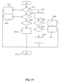
- Figure 14 depicts another procedure that calculates the forward and backward direction and finds the decision to stop the drive.
- step 2001 a check is performed to determine if the transponder with the RFID 7 and 8 are received. If not a step 2002 is executed, otherwise a step 2007 is executed.
- step 2002 a check is performed to determine if only the transponder with RFID 7 is received. In that case a step 2003 is executed, otherwise a step 2004 is executed.
- step 2004 a check is performed to determine if only the transponder with the RFID 8 is received. In that case a step 2005 is executed, otherwise a step 2006 is executed.
- step 2008 the difference of the signal strengths is compared to a second tolerance value tolerance NS.
- a step 2009 is executed. Otherwise the difference is too small and is ignored. In that case a step 2010 is executed.
- the second tolerance value toleranceNS is for example set by an administrator in the configuration.
- the second tolerance value toleranceNS is for example selected as 2 or 3 RSSI for high accuracy. Other second tolerance values may be used as well.
- This value indicates a weight for moving into forward direction and is temporarily stored. This value will be used in the final decision procedure as described in step 4 of the first method according to figure 11 .
- step 2013 is executed.
- step 2010 a check is performed to determine if the difference between the signal strengths DiffRSSI is less than the negative second tolerance value toleranceNS. In that case a step 2011 is executed. Otherwise the difference is too small and is ignored. In that case a step 2012 is executed.
- This value indicates a weight for moving into backward direction and is temporarily stored. This value will be used in the final decision procedure as described in step 4 of the first method according to figure 11 .
- step 2013 is executed.
- step 2012 a test is performed to determine if the RSSI values from the transponders with RFID 7 and RFID 8 are equal or within a predetermined third tolerance value.
- step 2013 is executed.
- step 2013 the return value is handed over and step 40 of the first method is continued.
- any functional blocks labelled as 'processors' may be provided through the use of dedicated hardware as well as hardware capable of executing software in association with appropriate software.
- the functions may be provided by a single dedicated processor, by a single shared processor, or by a plurality of individual processors, some of which may be shared.
- explicit use of the term 'processor' or 'controller' should not be construed to refer exclusively to hardware capable of executing software, and may implicitly include, without limitation, digital signal processor (DSP) hardware, network processor, application specific integrated circuit (ASIC), field programmable gate array (FPGA), read only memory (ROM) for storing software, random access memory (RAM), and non volatile storage.
- DSP digital signal processor
- ASIC application specific integrated circuit
- FPGA field programmable gate array
- ROM read only memory
- RAM random access memory
- any switches shown in the figures are conceptual only. Their function may be carried out through the operation of program logic, through dedicated logic, through the interaction of program control and dedicated logic, or even manually, the particular technique being selectable by the implementer as more specifically understood from the context.
- program storage devices e.g., digital data storage media, which are machine or computer readable and encode machine-executable or computer-executable programs of instructions, wherein said instructions perform some or all of the steps of said above-described methods.
- the program storage devices may be, e.g., digital memories, magnetic storage media such as a magnetic disks and magnetic tapes, hard drives, or optically readable digital data storage media.
- the embodiments are also intended to cover computers programmed to perform said steps of the above-described methods.
Landscapes
- Engineering & Computer Science (AREA)
- Transportation (AREA)
- Mechanical Engineering (AREA)
- Radar, Positioning & Navigation (AREA)
- Remote Sensing (AREA)
- Physics & Mathematics (AREA)
- Power Engineering (AREA)
- Automation & Control Theory (AREA)
- General Physics & Mathematics (AREA)
- Chemical & Material Sciences (AREA)
- Combustion & Propulsion (AREA)
- Computer Networks & Wireless Communication (AREA)
- Aviation & Aerospace Engineering (AREA)
- Electromagnetism (AREA)
- Position Fixing By Use Of Radio Waves (AREA)
Abstract
- detecting a second predetermined radio signal at a first receiver (121),
- detecting the first predetermined radio signal at a second receiver (122), and
determining the direction information depending on the reception of the first predetermined radio signal at the second receiver (122), in particular independent of the reception of the second predetermined radio signal, when the second predetermined radio signal is detected at the first receiver (121).
Description
- The present invention relates to a method and a device for determining direction information for guiding a vehicle to a predetermined position.
- In an implementation capable of determining direction information for guiding a vehicle to a predetermined position Global Positioning System Sensors are used to interact with geostationary satellites in order to determine the position of the vehicle, compare the position of the vehicle to the predetermined position using a map and to determine direction information such as navigation information depending thereon. This method often is restricted inside structures like parking decks because it depends on the availability of the satellite signals.
- In another implementation radar or ultrasonic sensors mounted to a vehicle are used to detect the area surrounding the vehicle and to determine direction information such as acoustic proximity warnings or a graphical representation of the vehicle and its surrounding area. This method relies on detection of objects like other cars or posts elevated above the surface area the vehicle is driving on and is therefore restricted to structures having such elevated objects.
- A further implementation uses optical sensors such as to detect markings on the surface the vehicle is driving on to generate acoustic signals or graphical representations of the vehicle and its surrounding area. Such sensors are susceptible to weather conditions as optical reflections caused by rain or snow may impact the reliability of the detection of the markings. Another implementation makes use of triangulation of radio signals in order to determine the current position of the vehicle. Such implementation uses the triangulation to determine the position of the vehicle in order to determine the direction information. This implementation is limited regarding the accuracy of the direction information in particular for vehicle with one steerable axle at the front because the orientation of the vehicle is unknown from the position itself.
- The object of the invention is thus to provide a highly reliable and accurate method and device for determining direction information for guiding a vehicle to a predetermined position.
- The main idea of the invention is to determine direction information for guiding a vehicle to a predetermined position depending on the reception of a first predetermined radio signal comprising
- detecting a second predetermined radio signal at a first receiver,
- detecting the first predetermined radio signal at a second receiver, and determining the direction information depending on the reception of the first predetermined radio signal at the second receiver, in particular independent of the reception of the second predetermined radio signal, when the second predetermined radio signal is detected at the first receiver. This way the orientation of the vehicle relative to the predetermined position is identified from the detection of the predetermined radio signals and is accounted for in the direction information.
- Advantageously the direction information is determined from the reception of the first predetermined radio signal at the first receiver when the first predetermined radio signal is detected at the first receiver and the second predetermined radio signal is not detected at the first receiver. This improves the direction information further by adding another detectable orientation of the vehicle.
- Advantageously a third predetermined radio signal is detected at the second receiver, and the direction information is determined depending on the difference between the reception of the first predetermined radio signal and a reception of the third predetermined radio signal at the second receiver. This improves the direction information by considering an additional predetermined radio signal when it is detected.
- Advantageously a left or right steering instruction is determined depending on the reception of the first predetermined radio signal or the third predetermined radio signal. This allows to create an output of the direction information easily understandable to a human driver or easily implementable by an actuator of an autonomous driving system.
- Advantageously a fourth predetermined radio signal is detected at the first receiver, and a forward or backward driving instruction is determined depending on the reception of the fourth predetermined radio signal. This further improves an output of the direction information easily understandable to a human driver or easily implementable by an actuator of an autonomous driving system.
- Advantageously the reception is determined depending on the signal strength of the respective predetermined radio signal. This provides an easy determination of the position of sender and receiver and allows the use of low cost or low range sender such as devices having oscillating circuits like active or passive radio frequency identification tags.
- Advantageously the direction information is determined from direction information previously determined and a current direction information, in particular the both combined depending on a predetermined value. This improves the direction information by increasing the robustness of the output generating either a continuous output by smoothing or averaging the direction information. Preferably an additive combination of the previously determined direction information and the current direction information is used in which the summands are weighted. For example the previously determined direction information is weighted by a factor corresponding to the predetermined value.
- The invention also concerns a device for determining direction information for guiding a vehicle to a predetermined position from the reception of a first predetermined radio signal comprising
- a first detector operable to detect a second predetermined radio signal at a first receiver,
- a second detector operable to detect the first predetermined radio signal at a second receiver, and
- a processing unit operable to determine the direction information from the reception of the first predetermined radio signal at the second receiver, in particular independent of the reception of the second predetermined radio signal, when the second predetermined radio signal is detected at the first receiver.
- Further developments of the invention can be gathered from dependent claims and the following description.
- In the following the invention will be explained further making reference to the attached drawings.
- Fig. 1-9
- schematically show states of a parking process of a vehicle on a parking structure;
- Fig. 10
- schematically shows a device for determining direction information;
- Fig. 11
- schematically shows a first flow chart of a part of a method for determining direction information.
- Fig. 12
- schematically shows a second flow chart of a part of a method for determining direction information.
- Fig. 13
- schematically shows a third flow chart of a part of a method for determining direction information,
- Fig. 14
- schematically shows a fourth flow chart of a part of a method for determining direction information.
-
Figures 1 - 9 depict aparking structure 120 and avehicle 100. Thevehicle 100 comprises in the example radiofrequency identification devices 101 to 109 that are adapted to send individual predetermined signals corresponding to the individual radio frequency identification device sending the signal. According to the example the radiofrequency identification devices 101 to 109 are mounted depending on their identification at predetermined positions of thevehicle 100. In the example the geometry of thevehicle 100 is approximately rectangular. The mounting position relative to the vehicle geometry and driving direction and the identification of the radiofrequency identification devices 101 to 109 is in the example:RFID mounting position radio frequency identification device 1011 front right radio frequency identification device 1022 front left radio frequency identification device 1033 mid to front right radio frequency identification device 1044 mid to front left radio frequency identification device 1055 middle right radio frequency identification device 1066 middle left radio frequency identification device 1077 mid to rear center radio frequency identification device 1088 rear center radio frequency identification device 1099 middle center - Any other amount of radio frequency identification devices or mounting positions may be used. For example only two radio frequency identification devices may be placed within a certain distance on the
vehicle 100. - The radio frequency identification devices may comprise an active or passive oscillating circuit adapted to send the respective RFID. This way the respective mounting position is derivable from the received signals. Accordingly the individual predetermined signals allow to identify the mounting position of the sender on the
vehicle 100. - A
parking structure 120 in the example offigures 1 - 9 is indicated by solid lines forming a rectangle that is open at one of the short ends. Markers of the parking structure indicate the dimensions of a parking lot for example using road marking color, pylons or curbs. - The
parking structure 120 in the example comprises afirst receiver 121 and asecond receiver 122. Thefirst receiver 121 and thesecond receiver 122 are mounted on theparking structure 120 or underneath the surface. Thefirst receiver 121 and thesecond receiver 122 may be mounted as depicted infigures 1 - 9 symmetrically on the longitudinal center axle of the rectangle indicating theparking structure 120. Likewise thefirst receiver 121 or thesecond receiver 122 may be mounted at any other position suitable to receive the signal of the radio frequency identification devices 101 - 109. They may for example be mounted on an axis connecting diagonally two corners of the rectangle as well as outside of the rectangle. - The
first receiver 121 or thesecond receiver 122 are adapted to receive the predetermined radio frequency identification signals from the radio frequency identification devices. To that end thefirst receiver 121 and thesecond receiver 122 are adapted to excite the active or passive oscillating circuit to send the respective RFID. Alternatively a separate sender not depicted infigures 1 - 9 may be used to excite the oscillating circuits as well. - In any way the mounting position of the
first receiver 121 and thesecond receiver 122 is such that individual predetermined signals can be received when thevehicle 100 is driving on theparking structure 120. - The maximum distance for reception of radio signals may vary depending on the radio signals, the mounting position or the surface properties. In the example the mounting position is such that radio signals from radio frequency identification devices mounted to the
vehicle 100 are receivable by thefirst receiver 121 or thesecond receiver 122 when thevehicle 100 approaches theparking structure 120. - In
figures 1 - 9 the predetermined radio signals of the radio frequency identification devices that are used in the respective situation for determining the direction information are depicted as circles filled solidly black. The predetermined radio signals of these are received by at least one of the receivers. Other predetermined radio signals still be received by one of the receivers. - Instead of using radio frequency identification devices 101 - 109 any other device suitable to transmit the same information may be used. Likewise the receivers that are mounted at the
parking structure 120 may be adapted to receive the respective signals. -
Figures 1 - 9 schematically show states of a parking process of thevehicle 100 on theparking structure 120. According tofigures 1 - 9 thevehicle 100 is suitable to fit into theparking structure 120. A predetermined target position of the vehicle is in the example offigures 1 - 9 reached when the vehicle is parked regarding three sides of the vehicle equidistantly relative to the solid lines forming the rectangle limiting theparking structure 120. This is depicted inFigure 9 . - This position, as depicted in
Figure 9 , results in a specific relative position of the radio frequency identification devices 101 - 108, thefirst receiver 121 and thesecond receiver 122. This specific relative position depends onindividual parking structures 120,individual vehicles 100 and individual mounting positions of the radio frequency identification devices 101 - 108. - In the example independent from the
vehicle 100 and theparking structure 120 the relative positions of the radio frequency identification devices 101 - 109 and thefirst receiver 121 and thesecond receiver 122 are identical. This may be achieved by installing the same set of radio frequency devices 101 - 109 at the same predetermined distances from each other on any vehicle equipped with this devices. Likewise thefirst receiver 121 and thesecond receiver 122 may be mounted at the same distance in a predetermined geometry regarding any parking structure. - Preferably the predetermined position that the
vehicle 100 is guided to describes an optimal parking position with respect to the alignment of a primary and secondary inductive coil of a wireless charging system. In this case the relative position of the radio frequency identification devices 101 - 109 and thefirst receiver 121 and thesecond receiver 122 are selected such that the two inductive coils are aligned optimally when thevehicle 100 is parked on theparking structure 120. - Optionally the alignment may be entirely independent of the
parking structure 120 orvehicle 100. In this case the predetermined position may depend only on the optimal alignment of the two inductive coils. - Likewise a tolerance band for the relative positions of the radio frequency identification devices 101 - 108 and the
first receiver 121 and thesecond receiver 122 may be used to allow some deviation from the predetermined position. - Instead of identical relative positions, the positions may be proportional by a predetermined factor or predetermined relation for
different vehicles 100, parking structures or inductive coil sizes or shapes. In any case the situation in which thevehicle 100 reaches the predetermined position is identifiable from this relative positions. -
Figures 1 - 9 schematically depict anoutput 131, e.g. a human machine interface, operable to receive and output the direction information. Theoutput 131 is for example mounted near theparking structure 120. Theoutput 131 may be a display operable to receive and display the direction information as depictedfigures 1 - 9 in form of anarrow 132. Thearrow 132 in the example indicates the driving direction. Likewise the direction information may be implemented as instructions, i.e. a left or right driving instruction, e.g. including steering angle, a forward or backward driving instruction or a combination of them. Such instructions may be coded as voice audio or graphical video instructions as well. - The display may be mounted near the
parking structure 120 visible to a driver of thevehicle 100 when approaching theparking structure 120. Likewise theoutput 131 may be a display inside thevehicle 100. In this case a sender not depicted infigures 1 - 9 may be used to send the direction information to theoutput 131. Optionally or alternatively instead of the display a sender for sending control commands to an autonomous driving system installed in thevehicle 100 may be used as well. - When a display is used, as depicted in
figure 9 thearrow 132 is visible as a point to indicate that the optimal position has been reached. In the other pictures the position of thearrow 132 depends on the direction information and indicates the target driving direction relative to the current position of the vehicle 110. This means that in figure one thearrow 132 indicates straight forward driving. The direction thearrow 132 points as depicted infigure 1 indicates for example 0 or 360 degrees of steering angle as forward driving direction. Other steering angles are subsequently indicated on a clockwise oriented scale in that - 1 to 90 degrees indicate right forward driving,
- 91 to 179 degrees indicate right backward driving,
- 180 degrees indicates straight backward driving,
- 181 to 269 degrees indicate left backward driving, and
- 270 to 359 degrees indicate left forward driving.
-
Figure 10 depicts adevice 200 for determining direction information for guiding thevehicle 100 to the predetermined position. - The
device 200 comprises afirst detector 201 connectable to thefirst receiver 121 and operable to detect the predetermined radio signals at thefirst receiver 121. - The
device 200 furthermore comprises asecond detector 202 connectable to thesecond receiver 122 and operable to detect the predetermined radio signals at asecond receiver 122. - The
output 131, when applicable the not depicted sender, and thedevice 200 as well as thefirst receiver 121 andsecond receiver 122 may be connected by wires. Alternatively any of this devices may be connected by wireless links. The connection may be for example via local area network (LAN), wireless local area network (WLAN, 802.11n) or wide area network (WAN). The connection can but must not be directly between the devices. - The
first detector 201 and thesecond detector 202 are in the example adapted to detect the presence of aforementioned predetermined radio signals from the respective radio frequency identification devices 101 - 109. - Furthermore the
first detector 201 and thesecond detector 202 are in the example adapted to determine the reception of this signals. Preferably the signal strengths of the detected predetermined radio signals is determined, e.g. in form of the Received Signal Strength Indication well known as RSSI. - The RSSI may be received from the any of the receivers in digital messages or as analog signals. In the first case the receivers comprise circuitry to generate the messages from signals received by an internal oscillating circuit. In the latter case the receivers may be antennas directly connectable to the detectors of the
device 200. - Furthermore the
device 200 comprises aprocessing unit 203 operable to interact with thefirst detector 201 and thesecond detector 202 to receive information about the predetermined radio signals, e.g. each detected predetermined radio signal and the reception thereof. Preferably the RFID of the signal and its RSSI is received by theprocessing unit 203. - The
processing unit 203 is operable to select the predetermined radio signals that are used for the determination of the direction information. Furthermore theprocessing unit 203 is operable to determine if thefirst receiver 121 or thesecond receiver 122 is selected as source at which the predetermined radio signal is detected. For example thefirst detector 201 or thesecond detector 202 detects any predetermined signal that is received at thefirst receiver 121 and thesecond receiver 122 respectively and theprocessing unit 203 selects which of the detectors is used as input for which of the detected signals. - According to the example the reception of a signal refers to the detected signal strength value, e.g. RSSI. In contrast, detecting of the signal refers to identifying the source of the signal, e.g. RFID.
- The
processing unit 203 is operable to determine the direction information from the reception of a first predetermined radio signal at thefirst receiver 121 when the first predetermined radio signal is detected at thefirst receiver 121 and a second predetermined radio signal is not detected at thefirst receiver 121. - In the example the second predetermined radio signal is defined as the signal from the middle center radio
frequency identification device 109 identifiable by theRFID 9. The first predetermined radio signal may be any other of the signals from any of the other frequency identification devices 101 - 108 identifiable by their respective RFID 1 - 8. This information is for example available to theprocessing unit 203 from storage. - An example for this case is depicted in
figure 2 . According tofigure 2 , due to the range of the radio signals being limited by design to a certain distance matching the aforementioned positions, only the front left radiofrequency identification device 102 is receipt by thefirst receiver 121. This means that in the example thefirst detector 201 detects the individual radio signal of the front left radiofrequency identification device 102 by itsRFID 2. Likewise the RSSI of this signal is detected by thefirst detector 201. Both are then provided to theprocessing unit 203. - The
processing unit 203 is then operable to upon receipt of this information, the RFID and RSSI, determine the direction information. In the example the direction information is determined as a target angle of the steering wheel resulting thedisplay 131 to depict thearrow 132 pointing forward left as shown infigure 2 . - The
processing unit 203 is further operable to determine the direction information from the reception, e.g. the RSSI, of the first predetermined radio signal at thesecond receiver 122, in particular independent of the reception, e.g. RSSI, of a second predetermined radio signal, when the second predetermined radio signal, e.g. the RFID, is detected at thefirst receiver 121. - An example for this case is depicted in
figure 6 . According to the situation depicted infigure 6 the second predetermined radio signal identified in the example by the RFID of the center radiofrequency identification device 109 is received by thefirst receiver 121. At the same time the predetermined signal of the front rightradio frequency device 101 is received at thesecond receiver 122. In this case theprocessing unit 203 is provided with the respective RFID and RSSI and independently of other radio signals detected by thefirst receiver 121 selects the predetermined radio signal received by thesecond receiver 122 as the first predetermined radio signal. As described before theprocessing unit 203 determines the direction information from the first predetermined radio signal, which as depicted infigure 6 results in theoutput 131 depicting anarrow 132 indicating the front right direction. - In a preferred example, the difference between the signal strengths of a group of radio frequency identification devices is used to determine the direction information. A group consists in the example of predetermined signals from at least two radio frequency identification devices that are grouped for example depending on the mounting position of the sending radio frequency identification device. Any other number of signals from radio frequency identification devices may be grouped together as well.
- The
processing unit 203 is operable to determine the grouping for example from the detected predetermined signals, e.g. their RFID, and stored information about the mounting positions. Likewise a mapping of RFID to predetermined groups may be used. - In a preferred example, the predetermined signals from the front left radio
frequency identification device 102 and front right radiofrequency identification device 101 belong to a first group. Furthermore the predetermined radio signals from the front to mid left radiofrequency identification device 104 and front to mid right radiofrequency identification device 103 belong to a second group. Furthermore the predetermined radio signals from the mid left radiofrequency identification device 106 and mid right radiofrequency identification device 105 belong to a third group. Furthermore the predetermined radio frequency signals from the mid to rear center radiofrequency identification device 107 and rear center radiofrequency identification device 108 belong to a fourth group. - The
processing unit 203 may be operable to determine the direction information depending on the difference between the reception of the first predetermined radio signal and a reception of a third predetermined radio signal at thefirst receiver 121 or thesecond receiver 122 when they belong to the same group. - To that end the
first detector 201 or thesecond detector 202 are operable to detect the respective signals, e.g. by the RFID and theprocessing unit 203 is operable to group them depending on the RFID as described above. Theprocessing unit 203 is further operable to group multiple predetermined radio signals detected into the appropriate group as well. - Likewise the
first detector 201, thesecond detector 202 and theprocessing unit 203 are operable to determine the difference between multiple groups of detected predetermined radio signals from information about the respective reception, e.g. RSSI. - When the signal strengths of individual predetermined radio signals, e.g. the RSSI, is used to determine the direction information directly or from the difference, the signal strength of the individual predetermined radio signal or the difference may be compared to a predetermined threshold and tolerance respectively to decide whether to use the information or not. The threshold or tolerance is for example accessible by the
processing unit 203 from storage of thedevice 200. The threshold or tolerance may be configurable via a human machine interface for example by an operator. Theprocessing unit 203 in this case may be operable to determine forward as direction information default value in case the threshold is not exceeded or the difference is within the tolerance. This way to small signal strengths or differences thereof are ignored. - Examples for such cases relating to the reception at the
first receiver 201 is depicted infigure 3 to 5 . Another example for such case relating to the reception at thesecond receiver 202 is depicted infigure 7 . - As depicted in
figure 3 , two predetermined radio signals are received at thefirst receiver 121. In this case the predetermined radio signal identified by theRFID 2 is selected as the first predetermined radio signal and the predetermined radio signal identified by the RFID 1 is selected as third predetermined radio signal. In this case theprocessing unit 203 determines that they belong to the same group, i.e. the first group. - In this case the
processing unit 203 is operable to determine the difference between the signal strengths of the two signals. Optionally the difference is compared to the threshold and only used when it exceeds the threshold. This way to small differences are ignored. In that case the direction information default is driving forward. In the example the difference is not too small and the direction information is determined from the difference to indicate driving forward and slightly left using thearrow 132 andoutput 131 as depicted infigure 3 . - As depicted in
figure 4 , three predetermined radio signals are received at thefirst receiver 121. In this case the predetermined radio signal identified by theRFID 3 is selected as the first predetermined radio signal and the predetermined radio signal identified by theRFID 4 is selected as third predetermined radio signal because they belong to the same group, i.e.group 2. The predetermined radio signal identified by theRFID 2 is ignored in this example. - Subsequently the direction information is determined as described above for
figure 3 . - As depicted in
figure 5 , four predetermined radio signals are received at thefirst receiver 121. In this case theprocessing unit 203 is adapted to analyze the predetermined radio signals per group. - Firstly for
group 2 the predetermined radio signal identified by theRFID 3 is selected as the first predetermined radio signal and the predetermined radio signal identified by theRFID 4 is selected as third predetermined radio signal because they belong to the same group, i.e.group 2. - Subsequently for
group 2 the direction information is determined as described above forfigure 3 . - Secondly for
group 3 the predetermined radio signal identified by theRFID 5 is selected as the first predetermined radio signal and the predetermined radio signal identified by theRFID 6 is selected as third predetermined radio signal because they belong to the same group, i.e.group 3. - Subsequently for
group 2 the direction information is determined as described above forfigure 3 . - Additionally when direction information from more than one group is available the
processing unit 203 is operable to determine the direction information from the direction information of the groups for example by averaging the direction information of the individual groups. - According to the situation depicted in
figure 7 , the predetermined radio signals of aforementioned group 1 are received at thesecond receiver 122. Furthermore according to this situation, the predetermined radio signals identified byRFIDs RFID 7 is ignored.
Preferably theprocessing unit 203 may be operable to determining a left or right steering instruction as intermediate step or final result depending on the reception of the first predetermined radio signal and the third predetermined radio signal. This is particularly useful to indicate only steering wheel angle for a driver or autonomous driving system. - Preferably the processing unit 303 may be operable to determine a forward or backward driving instruction depending on the reception of a fourth predetermined radio signal at the
first receiver 121. This may be used in particular in combination with separate driving angle information to indicate only forward or backward driving instructions to a driver while steering wheel operation is performed by an autonomous driving system using the indicated steering wheel angle. - In any case the direction information may be a number, e.g. an integer between 0 and 360 indicating clockwise the driving target direction wherein 0 and 360 indicate straight forward driving. Any other coding, such as individual indication for left or right and front or backward may be used as well.
- Preferably the
processing unit 203 is operable to store a previously determined direction information, e.g. the integer in storage. In this case theprocessing unit 203 is operable to access a predetermined value from storage, e.g. a forgetting factor between 0 and 1. In this example theprocessing unit 203 is operable to access the previously determined direction information from storage and determine a current direction information from the previously determined direction information and a current direction information by combining both depending on the predetermined value, e.g. by the formula
Xnew is the direction information,
beta is the predetermined value, e.g. the forgetting factor (0.0...1.0),
xt-1 is the previously determined direction information, and
xt is the currently calculated direction information. - The invention is not limited to this shape and size of the
parking structure 120 orvehicle 100 but may apply to any other size or form ofparking structure 120 orvehicle 100 as well. - The RSSI values in an example range between 60 and 120. Depending on the used RFID transponder or reader lower RSSI values may be used as well. The absolute value of the difference between the detected RSSI values hence ranges in the example between 40 and 60. However in other setups the absolute value may differ as well.
- A method for determining the direction information xt is described below. The resulting direction information xt is interpreted in an example as angles from 0 to 360 degrees where 0 and 360 degrees indicate straight forward driving and result in the examples of
figures 1 to 8 in the display of the arrow pointing into the respective directions. According the example infigure 9 the display of thearrow 132 as a point. This is mapped for example to the direction information xt = 999. - The direction information xt is for example initiated by the integer value xt=0 to indicate forward driving and may be stored in a temporary variable to be handed over between the first method and procedures called by this method.
- The method for example starts whenever the
vehicle 100 approaching theparking structure 120 is detected. This may be detected by a permanently processed detection routine using thefirst receiver 121 or another separate receiver adapted to detect any of the predetermined radio signals. - After the start the various parts of the method are executed as depicted in
figures 11 - 13 and explained below. The predetermined radio signals are in the exemplary method received from radio frequency identification devices labeled RFID transponder below. The direction information xt is determined based on a position correction calculation. Thefirst receiver 121 is in the example an antenna 1 and insecond receiver 122 is anantenna 2. -
Figure 11 depicts part of a first flow chart of a first method to handle a received RFID transponder and to start the position correction calculation. - The goal of this method is to analyze the received transponder and assign it to one of the groups. To that end the first method determines if the RSSI values are received from antenna 1 or
antenna 2. - After the start in a step 1 a check is performed to determine if the transponder is the transponder with the
RFID 8. If that is the case then step 2 is executed,else step 3 is executed. - In
step 2 the transponder information is stored in a temporary variable to use it in later calculation steps. Afterwards step 10 is executed. - In step 3 a check is performed to determine if the transponder is the transponder with the
RFID 7. If that is the case then step 4 is executedelse step 5 is executed. - In
step 4 the transponder information is stored in another temporary variable to use it in later calculation steps. Afterwards step 10 is executed. - In step 5 a check is performed to determine if the transponder is the transponder with the
RFID 9. If this is thecase step 6 is executed otherwisestep 7 is executed. - In
step 6 the input fromantenna 2 is used for determining direction information xt. When required the input is switched from antenna 1 toantenna 2. This means that the information fromantenna 2 is used for determining direction information xt instead of antenna 1. Preferably this is only the case for left and right direction instructions. Afterwards astep 8 is executed. - In
step 7 the input from antenna 1 is used for determining direction information xt. When required it is switched fromantenna 2 to use antenna 1. Preferably the input from antenna 1 is used for the left/right calculation and the information fromantenna 2 is not processed for this purpose. Afterwardsstep 8 is executed. - In
step 8 the received RFID transponder is not used for the forward/backward calculation but it is used for left/right calculation. In this step information about the groups is accessed. - In
step 9 the transponder is added to the transponder group corresponding to the RFID, e.g. by assigning one of the aforementioned groups to the RFID. Afterwards thestep 10 executed. - In
step 10 the position calculation method is started. This is described below referencingfigure 12 . Afterwards the step 1 is executed unless any interrupt is received ending this method. - The position calculation method triggers position calculation functions and combines the results from the actual calculation with previous results. To allow a smooth position change the previous results will be considered in combination with the new results by introducing the predetermined value, e.g. forgetting factor beta. This is explained referencing
figure 12 - After the start a
step 10 is executed. - In step 10 a procedure to calculate the left/right position correction information is called. This is described in detail referencing
Figure 13 below. - Afterwards a
step 20 is executed. - In
step 20 the current direction information xt is combined with the previously determined direction information xt-1 to a new direction information Xnew using the predetermined value, e.g. forgetting factor beta:
- Afterwards a
step 30 is executed. - In
step 30 the forward/backward position information is determined. This is described below in detail referencingfigure 14 . - Afterwards a
step 40 is executed. - In
step 40 the direction information xt is output, e.g. shown on the drive direction display (e.g. vehicle display, smart phone or other display devices). Afterwards the method ends, i.e. reverts to step 10 of the first method. -
Figure 13 depicts a procedure using all left/right transponder groups to calculate a decision for the left/right correction. Therefore it uses only the RSSI values and transponder information from antennas selected as described before in the first method referencingfigure 11 . - After the start a
step 1001 is executed. - In step 1001 a check is performed to determine if a transponder group is available which is not in a predetermined ignore list. The ignore list is initialized as empty list at the beginning of the method and filled with information about transponder groups that were already analyzed in previous loop cycles. If no group was found a
step 1016 is executed otherwise the transponder group found is selected and afterwards astep 1004 is executed. - In step 1004 a check is performed to determine if both transponders (left/right) of this group are received. If not step 1005 is executed otherwise
step 1010 is executed. - In step 1005 a check is performed to determine if another group with both transponders (left/right) is available and this transponder group is not on ignore list. If the transponder group is on ignored list it was analyzed but no direction decision was found. If another transponder group with both transponders is
available step 1001 is executed and select the next transponder group and put this transponder group on hold otherwise step 1006 is executed to start analyzes. - In step 1006 a check is performed to determine if the left transponder of this group was received. This is indicated by the RFID value of the transponder. If that is not the
case step 1008 is executed otherwisestep 1007 is executed. - In
step 1007 the direction information xt is determined to move left. This is for example indicated by setting xt = 270. Due to missing right transponder set the configured maximum aberrance value as return value which is defined by configuration and is a parameter to control the effect of this decision. This aberrance value is a maximum value that is used instead of the difference if only one transponder is received. In an example this value is set to an RSSI 15. It may depend on the forgetting factor, for example 15 at a forgetting factor 0.95. Tuning this value depending on the forgetting factor allows to improve the performance in varying setup of transponders. Afterwards step 1017 is executed. - In step 1008 a check is performed to determine if the right transponder of this group was received This is indicated by the RFID value of the transponder. If that is not the
case step 1001 is executed to select the next transponder group. Otherwise step 1009 is executed. - In
step 1009 the direction information is determined to move right. This is for example indicated by setting xt = 90. Due to missing left transponder set the configured maximum aberrance value as return value which is defined by configuration and is a parameter to control the effect of this decision. The maximum aberrance value is set for example as described above instep 1007. After thisstep 1017 is executed. - In
step 1010 the difference between the signal strengths is calculated from both available RSSI transponder values:
- Afterwards a
step 1011 is executed. - In
step 1011 the difference is compared to a first tolerance toleranceEW. In the example when the difference of signal strengths DiffRSSI is greater than a positive tolerance value astep 1012 is executed. Otherwise the difference is too small and will be ignored. In that case thestep 1013 is executed. - The first tolerance value toleranceEW is set for example by an administrator during configuration.
- In step 1012 a return value is determined depending on the difference between the signal strengths and the tolerance value. For example the return value is calculated as:

- This value indicates a weight for moving into left direction and is temporarily stored. This value will be used in the final decision procedure as described in
step 2 offigure 11 . - Afterwards the
step 1017 is executed - In
step 1013 the difference is compared to the first tolerance toleranceEW. In the example, when the difference between the signal strengths DiffRSSI is less than the negative first tolerance value toleranceEW astep 1014 is executed. Otherwise the difference is too small and will be ignored. In thatcase step 1015 is executed. - In
step 1014 the sum of the difference between the signal strengths DiffRSSI and the first tolerance value toleranceEW is determined as return value:
- The first tolerance value toleranceEW is for example selected as 2 or 3 RSSI for high accuracy. Other first tolerance values may be used as well.
- This value indicates a weight for moving into right direction and is temporarily stored. This value will be used in the final decision procedure as described in
step 2 of the first method according tofigure 11 . - Afterwards the
step 1017 is executed. - In step 1015 a left/right correction is determined using this transponder group. Because there is no great difference of RSSI values in this transponder group is added to the ignore list that is temporarily stored.
- Afterwards step 1001 is executed to check for additional transponder groups.
- In
step 1016 the direction information is determined to forward driving. This is for example indicated by setting xt=0. This is a default value that is used in this case because no decision to correct left/right position based on the available transponder group information can be made. - Afterwards step 1017 is executed.
- In
step 1017 the return value is handed over to the first method. Afterwards step 10 of the first method is continued. -
Figure 14 depicts another procedure that calculates the forward and backward direction and finds the decision to stop the drive. - In step 2001 a check is performed to determine if the transponder with the
RFID step 2002 is executed, otherwise astep 2007 is executed. - In step 2002 a check is performed to determine if only the transponder with
RFID 7 is received. In that case astep 2003 is executed, otherwise astep 2004 is executed. - In
step 2003 the direction information is set to move forward. This is for example indicated by setting xt=0. Afterwards astep 2013 is executed. - In step 2004 a check is performed to determine if only the transponder with the
RFID 8 is received. In that case astep 2005 is executed, otherwise astep 2006 is executed. - In
step 2005 the direction information is set to move backward. This is for example indicated by setting xt=180. Afterwards thestep 2013 is executed. - In
step 2006 the direction information is set to forward driving. This is for example indicated by setting xt=0. This is a default value because none of the transponders withRFID step 2013 is executed. - In
step 2007 the transponders withRFID 7 andRFID 8 are received and the difference of the RSSI values of both is calculated:
- Afterwards a
step 2008 is executed. - In
step 2008 the difference of the signal strengths is compared to a second tolerance value tolerance NS. When the difference DiffRSSI is greater than the positive second tolerance value toleranceNS astep 2009 is executed. Otherwise the difference is too small and is ignored. In that case astep 2010 is executed. - The second tolerance value toleranceNS is for example set by an administrator in the configuration.
- In
step 2009 another return value is determined depending on the difference between the signal strengths DiffRSSI and the second tolerance value toleranceNS:
- The second tolerance value toleranceNS is for example selected as 2 or 3 RSSI for high accuracy. Other second tolerance values may be used as well.
- This value indicates a weight for moving into forward direction and is temporarily stored. This value will be used in the final decision procedure as described in
step 4 of the first method according tofigure 11 . - Afterwards the
step 2013 is executed. - In step 2010 a check is performed to determine if the difference between the signal strengths DiffRSSI is less than the negative second tolerance value toleranceNS. In that case a
step 2011 is executed. Otherwise the difference is too small and is ignored. In that case astep 2012 is executed. - In
step 2011 the sum of the difference between the signal strengths DiffRSSI and the second tolerance value toleranceNS is determined as return value:
- This value indicates a weight for moving into backward direction and is temporarily stored. This value will be used in the final decision procedure as described in
step 4 of the first method according tofigure 11 . - Afterwards the
step 2013 is executed. - In step 2012 a test is performed to determine if the RSSI values from the transponders with
RFID 7 andRFID 8 are equal or within a predetermined third tolerance value. The third tolerance value is for example configured by an administrator. In case the RSSI values are equal or within the third tolerance value, the position is optimal. In that case the direction information is to stop the parking. This is for example indicated by setting xt=999. - This results in the example in the
arrow 132 being a point infigure 9 . - Afterwards step 2013 is executed.
- In
step 2013 the return value is handed over and step 40 of the first method is continued. - The description and drawings merely illustrate the principles of the invention. It will thus be appreciated that those skilled in the art will be able to devise various arrangements that, although not explicitly described or shown herein, embody the principles of the invention. All statements herein reciting principles, aspects, and embodiments of the invention, as well as specific examples thereof, are intended to encompass equivalents thereof.
- The functions of the various elements shown in the figures, including any functional blocks labelled as 'processors', may be provided through the use of dedicated hardware as well as hardware capable of executing software in association with appropriate software. When provided by a processor, the functions may be provided by a single dedicated processor, by a single shared processor, or by a plurality of individual processors, some of which may be shared. Moreover, explicit use of the term 'processor' or 'controller' should not be construed to refer exclusively to hardware capable of executing software, and may implicitly include, without limitation, digital signal processor (DSP) hardware, network processor, application specific integrated circuit (ASIC), field programmable gate array (FPGA), read only memory (ROM) for storing software, random access memory (RAM), and non volatile storage. Other hardware, conventional and/or custom, may also be included. Similarly, any switches shown in the figures are conceptual only. Their function may be carried out through the operation of program logic, through dedicated logic, through the interaction of program control and dedicated logic, or even manually, the particular technique being selectable by the implementer as more specifically understood from the context.
- It should be appreciated by those skilled in the art that any block diagrams herein represent conceptual views of illustrative circuitry embodying the principles of the invention. Similarly, it will be appreciated that the flow chart represents various processes which may be substantially represented in computer readable medium and so executed by a computer or processor, whether or not such computer or processor is explicitly shown.
- A person of skill in the art would readily recognize that steps of various above-described methods can be performed by programmed computers. Herein, some embodiments are also intended to cover program storage devices, e.g., digital data storage media, which are machine or computer readable and encode machine-executable or computer-executable programs of instructions, wherein said instructions perform some or all of the steps of said above-described methods. The program storage devices may be, e.g., digital memories, magnetic storage media such as a magnetic disks and magnetic tapes, hard drives, or optically readable digital data storage media. The embodiments are also intended to cover computers programmed to perform said steps of the above-described methods.
Claims (15)
- A method for determining direction information for guiding a vehicle (100) to a predetermined position depending on the reception of a first predetermined radio signal comprising- detecting (5) a second predetermined radio signal at a first receiver (121),- detecting (1,2,3,4) the first predetermined radio signal at a second receiver (122), and
determining (6) the direction information depending on the reception of the first predetermined radio signal at the second receiver (122), in particular independent of the reception of the second predetermined radio signal, when the second predetermined radio signal is detected at the first receiver (121). - The method according to claim 1, further comprising the step of determining (7) the direction information from the reception of the first predetermined radio signal at the first receiver (121) when the first predetermined radio signal is detected at the first receiver (121) and the second predetermined radio signal is not detected at the first receiver (121).
- The method according to claim 1 or 2, comprising detecting (1,2,3,4) a third predetermined radio signal at the second receiver (122), and determining (8) the direction information depending on the difference between the reception of the first predetermined radio signal and a reception of the third predetermined radio signal at the second receiver (122).
- The method according to any of the aforementioned claims, comprising determining (8) a left or right steering instruction depending on the reception of the first predetermined radio signal or the third predetermined radio signal.
- The method according to claim 3, comprising
detecting a fourth predetermined radio signal at the first receiver (121), and determining a forward or backward driving instruction depending on the reception of the fourth predetermined radio signal. - The method according to any of the aforementioned claims, wherein the reception is determined depending on the signal strength of the respective predetermined radio signal.
- The method according to any of the aforementioned claims, comprising determining the direction information from direction information previously determined and a current direction information, in particular the both combined depending on a predetermined value.
- A device (200) for determining direction information for guiding a vehicle (100) to a predetermined position from the reception of a first predetermined radio signal comprising- a first detector (201) operable to detect a second predetermined radio signal at a first receiver (121),- a second detector (202) operable to detect the first predetermined radio signal at a second receiver (122), and- a processing unit (203) operable to determine the direction information from the reception of the first predetermined radio signal at the second receiver (122), in particular independent of the reception of the second predetermined radio signal, when the second predetermined radio signal is detected at the first receiver (121).
- The device (200) according to claim 8, wherein the first detector (201) is further operable to detect the first predetermined radio signal at the first receiver (121), and the processing unit (203) is further operable to determine the direction information from the reception of the first predetermined radio signal at the first receiver (121) when the first predetermined radio signal is detected at the first receiver (121) and the second predetermined radio signal is not detected at the first receiver (121).
- The device (200) according to claim 8 or 9, wherein the second detector (202) is operable to detect a third predetermined radio signal at the second receiver (122), and the processing unit (203) is operable to determine the direction information depending on the difference between the reception of the first predetermined radio signal and a reception of the third predetermined radio signal at the second receiver (122).
- The device (200) according to any of claims 8 to 10, wherein the processing unit (203) is operable to determining a left or right steering instruction depending on the reception of the first predetermined radio signal or the third predetermined radio signal.
- The device (200) according to claim 11, wherein the first detector (201) is operable to detect a fourth predetermined radio signal at the first receiver (121), and the processing unit (203) is operable to determine a forward or backward driving instruction depending on the reception of the fourth predetermined radio signal.
- The device (200) according to any of claims 8 to 12, wherein the reception is determined depending on the signal strength of the respective predetermined radio signal.
- The device (200) according to any of claims 8 to 13, wherein the processing unit (203) is operable to store a previously determined the direction information and to determine the direction information from the previously determined direction information and a current direction, in particular the both combined depending on a predetermined value.
- A computer program for determining direction information for guiding a vehicle (100) into a predetermined position, wherein said computer program, when executed on a computer, causes the computer to perform the steps of the method according to any of claims 1 to 7.
Priority Applications (1)
| Application Number | Priority Date | Filing Date | Title |
|---|---|---|---|
| EP14305388.2A EP2921376B1 (en) | 2014-03-19 | 2014-03-19 | A method and device for determining direction information for guiding a vehicle to a predetermined position |
Applications Claiming Priority (1)
| Application Number | Priority Date | Filing Date | Title |
|---|---|---|---|
| EP14305388.2A EP2921376B1 (en) | 2014-03-19 | 2014-03-19 | A method and device for determining direction information for guiding a vehicle to a predetermined position |
Publications (2)
| Publication Number | Publication Date |
|---|---|
| EP2921376A1 true EP2921376A1 (en) | 2015-09-23 |
| EP2921376B1 EP2921376B1 (en) | 2017-12-13 |
Family
ID=50473225
Family Applications (1)
| Application Number | Title | Priority Date | Filing Date |
|---|---|---|---|
| EP14305388.2A Active EP2921376B1 (en) | 2014-03-19 | 2014-03-19 | A method and device for determining direction information for guiding a vehicle to a predetermined position |
Country Status (1)
| Country | Link |
|---|---|
| EP (1) | EP2921376B1 (en) |
Cited By (4)
| Publication number | Priority date | Publication date | Assignee | Title |
|---|---|---|---|---|
| CN109606149A (en) * | 2018-10-26 | 2019-04-12 | 惠州市德赛西威汽车电子股份有限公司 | A wireless charging positioning method and system |
| CN109765904A (en) * | 2019-02-28 | 2019-05-17 | 上海木木聚枞机器人科技有限公司 | A kind of guidance control method and mobile device of mobile device disengaging narrow space |
| EP3648303A1 (en) * | 2018-10-31 | 2020-05-06 | Hyundai Motor Company | Apparatus and method for measuring vehicle position based on low frequency signals |
| CN114089731A (en) * | 2020-08-07 | 2022-02-25 | 宝时得科技(中国)有限公司 | Outdoor robot access channel control method and device and storage medium |
Families Citing this family (1)
| Publication number | Priority date | Publication date | Assignee | Title |
|---|---|---|---|---|
| DE102018207394A1 (en) | 2018-05-14 | 2019-11-14 | Volkswagen Aktiengesellschaft | Positioning method for inductive charging of electric vehicles |
Citations (5)
| Publication number | Priority date | Publication date | Assignee | Title |
|---|---|---|---|---|
| US20010027360A1 (en) * | 2000-03-30 | 2001-10-04 | Kanazawa Institute Of Technology | Navigating method and device for an autonomus vehicle |
| US20040113787A1 (en) * | 2002-12-12 | 2004-06-17 | Smith Randall B. | Method and apparatus for using rfid tags to determine the postion of an object |
| WO2007057969A1 (en) * | 2005-11-18 | 2007-05-24 | Ajinomoto Co., Inc. | Position detection system, position detection program, position detection device, and position detection method |
| US20120095617A1 (en) * | 2011-10-06 | 2012-04-19 | Ford Global Technologies, Llc | Vehicle guidance system |
| US20120262002A1 (en) * | 2011-04-13 | 2012-10-18 | Qualcomm Incorporated | Antenna alignment and vehicle guidance for wireless charging of electric vehicles |
-
2014
- 2014-03-19 EP EP14305388.2A patent/EP2921376B1/en active Active
Patent Citations (5)
| Publication number | Priority date | Publication date | Assignee | Title |
|---|---|---|---|---|
| US20010027360A1 (en) * | 2000-03-30 | 2001-10-04 | Kanazawa Institute Of Technology | Navigating method and device for an autonomus vehicle |
| US20040113787A1 (en) * | 2002-12-12 | 2004-06-17 | Smith Randall B. | Method and apparatus for using rfid tags to determine the postion of an object |
| WO2007057969A1 (en) * | 2005-11-18 | 2007-05-24 | Ajinomoto Co., Inc. | Position detection system, position detection program, position detection device, and position detection method |
| US20120262002A1 (en) * | 2011-04-13 | 2012-10-18 | Qualcomm Incorporated | Antenna alignment and vehicle guidance for wireless charging of electric vehicles |
| US20120095617A1 (en) * | 2011-10-06 | 2012-04-19 | Ford Global Technologies, Llc | Vehicle guidance system |
Cited By (6)
| Publication number | Priority date | Publication date | Assignee | Title |
|---|---|---|---|---|
| CN109606149A (en) * | 2018-10-26 | 2019-04-12 | 惠州市德赛西威汽车电子股份有限公司 | A wireless charging positioning method and system |
| EP3648303A1 (en) * | 2018-10-31 | 2020-05-06 | Hyundai Motor Company | Apparatus and method for measuring vehicle position based on low frequency signals |
| US11264844B2 (en) | 2018-10-31 | 2022-03-01 | Hyundai Motor Company | Apparatus and method for measuring vehicle position based on low frequency signals |
| US11552509B2 (en) | 2018-10-31 | 2023-01-10 | Hyundai Motor Company | Apparatus and method for measuring vehicle position based on low frequency signals |
| CN109765904A (en) * | 2019-02-28 | 2019-05-17 | 上海木木聚枞机器人科技有限公司 | A kind of guidance control method and mobile device of mobile device disengaging narrow space |
| CN114089731A (en) * | 2020-08-07 | 2022-02-25 | 宝时得科技(中国)有限公司 | Outdoor robot access channel control method and device and storage medium |
Also Published As
| Publication number | Publication date |
|---|---|
| EP2921376B1 (en) | 2017-12-13 |
Similar Documents
| Publication | Publication Date | Title |
|---|---|---|
| US10558869B2 (en) | Location specifying apparatus and non-transitory computer-readable medium | |
| EP2921376B1 (en) | A method and device for determining direction information for guiding a vehicle to a predetermined position | |
| EP3637371B1 (en) | Map data correcting method and device | |
| US10821844B2 (en) | Method and device for determining the absolute position of a vehicle | |
| RU2720140C1 (en) | Method for self-position estimation and self-position estimation device | |
| US9802501B2 (en) | Guided vehicle positioning for inductive charging with the assistance of a vehicle camera | |
| KR102387774B1 (en) | Variable range and frame-rate radar operation for automated vehicles | |
| CN107272001B (en) | External-of-sight obstacle detection and location | |
| US20180347991A1 (en) | Method, device, map management apparatus, and system for precision-locating a motor vehicle in an environment | |
| US20220113139A1 (en) | Object recognition device, object recognition method and program | |
| US20200341111A1 (en) | Method and apparatus for radar detection confirmation | |
| JP6838365B2 (en) | Self-position estimation method and self-position estimation device | |
| CN112975976A (en) | Article checking method and system, robot control device and robot | |
| US9759575B2 (en) | Method for supporting a driver during the positioning of a motor vehicle | |
| JP2017117105A (en) | Line-of-sight judgment device | |
| JP2020087307A (en) | Self position estimating apparatus, self position estimating method, and cargo handling system | |
| US10969785B2 (en) | Automated vehicle operation to compensate for sensor field-of-view limitations | |
| EP3477259A1 (en) | Method and system for estimating quality of measuring results of one of more sensors mounted on a mobile platform | |
| US12097779B2 (en) | Relative pose determination of primary and secondary winding structures in inductive power transfer system | |
| JP7812476B2 (en) | Measurement device, measurement method, program, and storage medium | |
| JP2024177451A (en) | Measurement device, measurement method, and program | |
| CN116242334B (en) | Port lock station-oriented vehicle positioning method and system | |
| EP3796031B1 (en) | A method for reducing the amount of sensor data from a forward-looking vehicle sensor | |
| WO2018195741A1 (en) | Driving environment identification method and system | |
| KR20240147113A (en) | Method and apparatus for determining the initial position of a vehicle |
Legal Events
| Date | Code | Title | Description |
|---|---|---|---|
| PUAI | Public reference made under article 153(3) epc to a published international application that has entered the european phase |
Free format text: ORIGINAL CODE: 0009012 |
|
| AK | Designated contracting states |
Kind code of ref document: A1 Designated state(s): AL AT BE BG CH CY CZ DE DK EE ES FI FR GB GR HR HU IE IS IT LI LT LU LV MC MK MT NL NO PL PT RO RS SE SI SK SM TR |
|
| AX | Request for extension of the european patent |
Extension state: BA ME |
|
| 17P | Request for examination filed |
Effective date: 20160323 |
|
| RBV | Designated contracting states (corrected) |
Designated state(s): AL AT BE BG CH CY CZ DE DK EE ES FI FR GB GR HR HU IE IS IT LI LT LU LV MC MK MT NL NO PL PT RO RS SE SI SK SM TR |
|
| RIC1 | Information provided on ipc code assigned before grant |
Ipc: B62D 15/02 20060101AFI20160713BHEP Ipc: G01C 21/26 20060101ALI20160713BHEP Ipc: G05D 1/02 20060101ALI20160713BHEP Ipc: B60L 11/18 20060101ALI20160713BHEP Ipc: G06K 7/10 20060101ALI20160713BHEP |
|
| 17Q | First examination report despatched |
Effective date: 20160803 |
|
| GRAP | Despatch of communication of intention to grant a patent |
Free format text: ORIGINAL CODE: EPIDOSNIGR1 |
|
| INTG | Intention to grant announced |
Effective date: 20170728 |
|
| GRAS | Grant fee paid |
Free format text: ORIGINAL CODE: EPIDOSNIGR3 |
|
| GRAA | (expected) grant |
Free format text: ORIGINAL CODE: 0009210 |
|
| REG | Reference to a national code |
Ref country code: GB Ref legal event code: FG4D |
|
| REG | Reference to a national code |
Ref country code: AT Ref legal event code: REF Ref document number: 954073 Country of ref document: AT Kind code of ref document: T Effective date: 20171215 Ref country code: CH Ref legal event code: EP |
|
| REG | Reference to a national code |
Ref country code: IE Ref legal event code: FG4D |
|
| REG | Reference to a national code |
Ref country code: DE Ref legal event code: R096 Ref document number: 602014018425 Country of ref document: DE |
|
| REG | Reference to a national code |
Ref country code: FR Ref legal event code: PLFP Year of fee payment: 5 |
|
| REG | Reference to a national code |
Ref country code: CH Ref legal event code: PCOW Free format text: NEW ADDRESS: SITE NOKIA PARIS SACLAY ROUTE DE VILLEJUST, 91620 NOZAY (FR) |
|
| RAP2 | Party data changed (patent owner data changed or rights of a patent transferred) |
Owner name: ALCATEL LUCENT |
|
| REG | Reference to a national code |
Ref country code: NL Ref legal event code: MP Effective date: 20171213 |
|
| PG25 | Lapsed in a contracting state [announced via postgrant information from national office to epo] |
Ref country code: NO Free format text: LAPSE BECAUSE OF FAILURE TO SUBMIT A TRANSLATION OF THE DESCRIPTION OR TO PAY THE FEE WITHIN THE PRESCRIBED TIME-LIMIT Effective date: 20180313 Ref country code: SE Free format text: LAPSE BECAUSE OF FAILURE TO SUBMIT A TRANSLATION OF THE DESCRIPTION OR TO PAY THE FEE WITHIN THE PRESCRIBED TIME-LIMIT Effective date: 20171213 Ref country code: FI Free format text: LAPSE BECAUSE OF FAILURE TO SUBMIT A TRANSLATION OF THE DESCRIPTION OR TO PAY THE FEE WITHIN THE PRESCRIBED TIME-LIMIT Effective date: 20171213 |
|
| REG | Reference to a national code |
Ref country code: AT Ref legal event code: MK05 Ref document number: 954073 Country of ref document: AT Kind code of ref document: T Effective date: 20171213 |
|
| PG25 | Lapsed in a contracting state [announced via postgrant information from national office to epo] |
Ref country code: RS Free format text: LAPSE BECAUSE OF FAILURE TO SUBMIT A TRANSLATION OF THE DESCRIPTION OR TO PAY THE FEE WITHIN THE PRESCRIBED TIME-LIMIT Effective date: 20171213 Ref country code: HR Free format text: LAPSE BECAUSE OF FAILURE TO SUBMIT A TRANSLATION OF THE DESCRIPTION OR TO PAY THE FEE WITHIN THE PRESCRIBED TIME-LIMIT Effective date: 20171213 Ref country code: BG Free format text: LAPSE BECAUSE OF FAILURE TO SUBMIT A TRANSLATION OF THE DESCRIPTION OR TO PAY THE FEE WITHIN THE PRESCRIBED TIME-LIMIT Effective date: 20180313 Ref country code: GR Free format text: LAPSE BECAUSE OF FAILURE TO SUBMIT A TRANSLATION OF THE DESCRIPTION OR TO PAY THE FEE WITHIN THE PRESCRIBED TIME-LIMIT Effective date: 20180314 Ref country code: LV Free format text: LAPSE BECAUSE OF FAILURE TO SUBMIT A TRANSLATION OF THE DESCRIPTION OR TO PAY THE FEE WITHIN THE PRESCRIBED TIME-LIMIT Effective date: 20171213 |
|
| PG25 | Lapsed in a contracting state [announced via postgrant information from national office to epo] |
Ref country code: NL Free format text: LAPSE BECAUSE OF FAILURE TO SUBMIT A TRANSLATION OF THE DESCRIPTION OR TO PAY THE FEE WITHIN THE PRESCRIBED TIME-LIMIT Effective date: 20171213 |
|
| PG25 | Lapsed in a contracting state [announced via postgrant information from national office to epo] |
Ref country code: EE Free format text: LAPSE BECAUSE OF FAILURE TO SUBMIT A TRANSLATION OF THE DESCRIPTION OR TO PAY THE FEE WITHIN THE PRESCRIBED TIME-LIMIT Effective date: 20171213 Ref country code: CY Free format text: LAPSE BECAUSE OF FAILURE TO SUBMIT A TRANSLATION OF THE DESCRIPTION OR TO PAY THE FEE WITHIN THE PRESCRIBED TIME-LIMIT Effective date: 20171213 Ref country code: CZ Free format text: LAPSE BECAUSE OF FAILURE TO SUBMIT A TRANSLATION OF THE DESCRIPTION OR TO PAY THE FEE WITHIN THE PRESCRIBED TIME-LIMIT Effective date: 20171213 Ref country code: SK Free format text: LAPSE BECAUSE OF FAILURE TO SUBMIT A TRANSLATION OF THE DESCRIPTION OR TO PAY THE FEE WITHIN THE PRESCRIBED TIME-LIMIT Effective date: 20171213 Ref country code: ES Free format text: LAPSE BECAUSE OF FAILURE TO SUBMIT A TRANSLATION OF THE DESCRIPTION OR TO PAY THE FEE WITHIN THE PRESCRIBED TIME-LIMIT Effective date: 20171213 |
|
| PG25 | Lapsed in a contracting state [announced via postgrant information from national office to epo] |
Ref country code: SM Free format text: LAPSE BECAUSE OF FAILURE TO SUBMIT A TRANSLATION OF THE DESCRIPTION OR TO PAY THE FEE WITHIN THE PRESCRIBED TIME-LIMIT Effective date: 20171213 Ref country code: AT Free format text: LAPSE BECAUSE OF FAILURE TO SUBMIT A TRANSLATION OF THE DESCRIPTION OR TO PAY THE FEE WITHIN THE PRESCRIBED TIME-LIMIT Effective date: 20171213 Ref country code: IT Free format text: LAPSE BECAUSE OF FAILURE TO SUBMIT A TRANSLATION OF THE DESCRIPTION OR TO PAY THE FEE WITHIN THE PRESCRIBED TIME-LIMIT Effective date: 20171213 Ref country code: IS Free format text: LAPSE BECAUSE OF FAILURE TO SUBMIT A TRANSLATION OF THE DESCRIPTION OR TO PAY THE FEE WITHIN THE PRESCRIBED TIME-LIMIT Effective date: 20180413 Ref country code: RO Free format text: LAPSE BECAUSE OF FAILURE TO SUBMIT A TRANSLATION OF THE DESCRIPTION OR TO PAY THE FEE WITHIN THE PRESCRIBED TIME-LIMIT Effective date: 20171213 Ref country code: PL Free format text: LAPSE BECAUSE OF FAILURE TO SUBMIT A TRANSLATION OF THE DESCRIPTION OR TO PAY THE FEE WITHIN THE PRESCRIBED TIME-LIMIT Effective date: 20171213 |
|
| REG | Reference to a national code |
Ref country code: DE Ref legal event code: R097 Ref document number: 602014018425 Country of ref document: DE |
|
| PLBE | No opposition filed within time limit |
Free format text: ORIGINAL CODE: 0009261 |
|
| STAA | Information on the status of an ep patent application or granted ep patent |
Free format text: STATUS: NO OPPOSITION FILED WITHIN TIME LIMIT |
|
| REG | Reference to a national code |
Ref country code: CH Ref legal event code: PL |
|
| 26N | No opposition filed |
Effective date: 20180914 |
|
| PG25 | Lapsed in a contracting state [announced via postgrant information from national office to epo] |
Ref country code: DK Free format text: LAPSE BECAUSE OF FAILURE TO SUBMIT A TRANSLATION OF THE DESCRIPTION OR TO PAY THE FEE WITHIN THE PRESCRIBED TIME-LIMIT Effective date: 20171213 Ref country code: MC Free format text: LAPSE BECAUSE OF FAILURE TO SUBMIT A TRANSLATION OF THE DESCRIPTION OR TO PAY THE FEE WITHIN THE PRESCRIBED TIME-LIMIT Effective date: 20171213 |
|
| REG | Reference to a national code |
Ref country code: BE Ref legal event code: MM Effective date: 20180331 |
|
| REG | Reference to a national code |
Ref country code: IE Ref legal event code: MM4A |
|
| PG25 | Lapsed in a contracting state [announced via postgrant information from national office to epo] |
Ref country code: LU Free format text: LAPSE BECAUSE OF NON-PAYMENT OF DUE FEES Effective date: 20180319 |
|
| PG25 | Lapsed in a contracting state [announced via postgrant information from national office to epo] |
Ref country code: IE Free format text: LAPSE BECAUSE OF NON-PAYMENT OF DUE FEES Effective date: 20180319 |
|
| PG25 | Lapsed in a contracting state [announced via postgrant information from national office to epo] |
Ref country code: SI Free format text: LAPSE BECAUSE OF FAILURE TO SUBMIT A TRANSLATION OF THE DESCRIPTION OR TO PAY THE FEE WITHIN THE PRESCRIBED TIME-LIMIT Effective date: 20171213 Ref country code: LI Free format text: LAPSE BECAUSE OF NON-PAYMENT OF DUE FEES Effective date: 20180331 Ref country code: CH Free format text: LAPSE BECAUSE OF NON-PAYMENT OF DUE FEES Effective date: 20180331 Ref country code: BE Free format text: LAPSE BECAUSE OF NON-PAYMENT OF DUE FEES Effective date: 20180331 |
|
| PGFP | Annual fee paid to national office [announced via postgrant information from national office to epo] |
Ref country code: FR Payment date: 20190213 Year of fee payment: 6 |
|
| PG25 | Lapsed in a contracting state [announced via postgrant information from national office to epo] |
Ref country code: MT Free format text: LAPSE BECAUSE OF NON-PAYMENT OF DUE FEES Effective date: 20180319 |
|
| PG25 | Lapsed in a contracting state [announced via postgrant information from national office to epo] |
Ref country code: TR Free format text: LAPSE BECAUSE OF FAILURE TO SUBMIT A TRANSLATION OF THE DESCRIPTION OR TO PAY THE FEE WITHIN THE PRESCRIBED TIME-LIMIT Effective date: 20171213 |
|
| PG25 | Lapsed in a contracting state [announced via postgrant information from national office to epo] |
Ref country code: PT Free format text: LAPSE BECAUSE OF FAILURE TO SUBMIT A TRANSLATION OF THE DESCRIPTION OR TO PAY THE FEE WITHIN THE PRESCRIBED TIME-LIMIT Effective date: 20171213 |
|
| PG25 | Lapsed in a contracting state [announced via postgrant information from national office to epo] |
Ref country code: MK Free format text: LAPSE BECAUSE OF NON-PAYMENT OF DUE FEES Effective date: 20171213 Ref country code: HU Free format text: LAPSE BECAUSE OF FAILURE TO SUBMIT A TRANSLATION OF THE DESCRIPTION OR TO PAY THE FEE WITHIN THE PRESCRIBED TIME-LIMIT; INVALID AB INITIO Effective date: 20140319 Ref country code: LT Free format text: LAPSE BECAUSE OF FAILURE TO SUBMIT A TRANSLATION OF THE DESCRIPTION OR TO PAY THE FEE WITHIN THE PRESCRIBED TIME-LIMIT Effective date: 20171213 |
|
| PG25 | Lapsed in a contracting state [announced via postgrant information from national office to epo] |
Ref country code: AL Free format text: LAPSE BECAUSE OF FAILURE TO SUBMIT A TRANSLATION OF THE DESCRIPTION OR TO PAY THE FEE WITHIN THE PRESCRIBED TIME-LIMIT Effective date: 20171213 |
|
| PG25 | Lapsed in a contracting state [announced via postgrant information from national office to epo] |
Ref country code: FR Free format text: LAPSE BECAUSE OF NON-PAYMENT OF DUE FEES Effective date: 20200331 |
|
| PGFP | Annual fee paid to national office [announced via postgrant information from national office to epo] |
Ref country code: GB Payment date: 20260202 Year of fee payment: 13 |
|
| PGFP | Annual fee paid to national office [announced via postgrant information from national office to epo] |
Ref country code: DE Payment date: 20260204 Year of fee payment: 13 |