EP2921090A1 - Anti-rotational latch for a blending appliance - Google Patents
Anti-rotational latch for a blending appliance Download PDFInfo
- Publication number
- EP2921090A1 EP2921090A1 EP15159050.2A EP15159050A EP2921090A1 EP 2921090 A1 EP2921090 A1 EP 2921090A1 EP 15159050 A EP15159050 A EP 15159050A EP 2921090 A1 EP2921090 A1 EP 2921090A1
- Authority
- EP
- European Patent Office
- Prior art keywords
- jar
- articulating arm
- blender
- retainer mechanism
- blender jar
- Prior art date
- Legal status (The legal status is an assumption and is not a legal conclusion. Google has not performed a legal analysis and makes no representation as to the accuracy of the status listed.)
- Withdrawn
Links
- 238000002156 mixing Methods 0.000 title claims abstract description 49
- 230000007246 mechanism Effects 0.000 claims abstract description 44
- 230000008878 coupling Effects 0.000 claims description 17
- 238000010168 coupling process Methods 0.000 claims description 17
- 238000005859 coupling reaction Methods 0.000 claims description 17
- 230000000717 retained effect Effects 0.000 claims description 5
- 238000000034 method Methods 0.000 description 4
- 230000000694 effects Effects 0.000 description 2
- 230000009977 dual effect Effects 0.000 description 1
- 239000004615 ingredient Substances 0.000 description 1
- 239000000696 magnetic material Substances 0.000 description 1
- 239000000203 mixture Substances 0.000 description 1
- 230000002028 premature Effects 0.000 description 1
- 239000007787 solid Substances 0.000 description 1
Images





Classifications
-
- A—HUMAN NECESSITIES
- A47—FURNITURE; DOMESTIC ARTICLES OR APPLIANCES; COFFEE MILLS; SPICE MILLS; SUCTION CLEANERS IN GENERAL
- A47J—KITCHEN EQUIPMENT; COFFEE MILLS; SPICE MILLS; APPARATUS FOR MAKING BEVERAGES
- A47J43/00—Implements for preparing or holding food, not provided for in other groups of this subclass
- A47J43/04—Machines for domestic use not covered elsewhere, e.g. for grinding, mixing, stirring, kneading, emulsifying, whipping or beating foodstuffs, e.g. power-driven
- A47J43/046—Machines for domestic use not covered elsewhere, e.g. for grinding, mixing, stirring, kneading, emulsifying, whipping or beating foodstuffs, e.g. power-driven with tools driven from the bottom side
- A47J43/0465—Machines for domestic use not covered elsewhere, e.g. for grinding, mixing, stirring, kneading, emulsifying, whipping or beating foodstuffs, e.g. power-driven with tools driven from the bottom side with magnetic drive
-
- A—HUMAN NECESSITIES
- A47—FURNITURE; DOMESTIC ARTICLES OR APPLIANCES; COFFEE MILLS; SPICE MILLS; SUCTION CLEANERS IN GENERAL
- A47J—KITCHEN EQUIPMENT; COFFEE MILLS; SPICE MILLS; APPARATUS FOR MAKING BEVERAGES
- A47J43/00—Implements for preparing or holding food, not provided for in other groups of this subclass
- A47J43/04—Machines for domestic use not covered elsewhere, e.g. for grinding, mixing, stirring, kneading, emulsifying, whipping or beating foodstuffs, e.g. power-driven
- A47J43/046—Machines for domestic use not covered elsewhere, e.g. for grinding, mixing, stirring, kneading, emulsifying, whipping or beating foodstuffs, e.g. power-driven with tools driven from the bottom side
-
- A—HUMAN NECESSITIES
- A47—FURNITURE; DOMESTIC ARTICLES OR APPLIANCES; COFFEE MILLS; SPICE MILLS; SUCTION CLEANERS IN GENERAL
- A47J—KITCHEN EQUIPMENT; COFFEE MILLS; SPICE MILLS; APPARATUS FOR MAKING BEVERAGES
- A47J43/00—Implements for preparing or holding food, not provided for in other groups of this subclass
- A47J43/04—Machines for domestic use not covered elsewhere, e.g. for grinding, mixing, stirring, kneading, emulsifying, whipping or beating foodstuffs, e.g. power-driven
- A47J43/07—Parts or details, e.g. mixing tools, whipping tools
- A47J43/075—Safety devices
- A47J43/0761—Safety devices for machines with tools driven from the lower side
- A47J43/0766—Safety devices for machines with tools driven from the lower side activated by the proper positioning of the mixing bowl
Definitions
- the present concept generally relates to a blending appliance, and more particularly to a blending appliance having a magnetic coupler system and an anti-rotational latch mechanism retaining a blender jar on a housing of the blending appliance.
- Countertop blending appliances may be generally driven through a motor configured in a base unit of the appliance directly below a blender jar.
- the blender jar having a mixing chamber, may generally be removably configured on a top surface of the base unit.
- the mixing chamber may generally include a mixing element rotatively connected to the drive motor through a selectively engaging male gear extending from a base of the blender jar.
- the male gear is generally received in a corresponding female gear connected directly to the drive motor and configured to drive the mixing element when engaged with the male gear.
- One aspect of the present concept includes a jar retainer mechanism for a blending appliance, wherein the blending appliance includes a housing having an upper housing member and a base portion with a jar receiving portion defined therebetween.
- a blender jar is configured to be laterally received in the jar receiving portion and includes an engagement tab disposed on a base portion of the blender jar.
- An articulating arm is coupled to the base portion of the housing and is operable between engaged and disengaged positions.
- the articulating arm includes a latch member configured to engage the engagement tab of the blender jar when the articulating arm is in the engaged position and the blender jar is received in the jar receiving portion.
- a jar retainer mechanism for a blending appliance having an articulating arm pivotally coupled to a housing of the blending appliance.
- the articulating arm is operable between engaged and disengaged positions and includes a latch member disposed on a first end of the articulating arm.
- the latch member is configured to engage an engagement tab disposed on the blender jar when the articulating arm is in the engaged position and the blender jar is received laterally in the jar receiving portion.
- a push member is disposed on a second end of the articulating arm and is configured to displace the blender jar when the articulating arm is moved towards the disengaged position.
- Yet another aspect of the present concept includes a jar retainer mechanism for a blending appliance, wherein the blending appliance includes a housing having an upper housing member and a base portion with a jar receiving portion defined therebetween.
- a blender jar having a base portion with an outwardly extending engagement tab is configured to be laterally received in the jar receiving portion of the housing.
- An articulating arm is coupled to the base portion of the housing and is operable between engaged and disengaged positions.
- the articulating arm includes a latch member configured to engage the engagement tab of the blender jar when the articulating arm is in the engaged position and the blender jar is received laterally in the jar receiving portion.
- a magnetic coupling system includes upper and lower magnetic couplers, wherein the upper magnetic coupler is disposed in the base portion of the blender jar and the lower magnetic coupler is disposed in the base portion of the housing.
- the reference numeral 10 generally designates a blender jar having a side wall 12 which generally defines a blending cavity 14 accessible through an open upper end 16.
- the open upper end 16 includes a spout portion 18 and further has a generally teardrop shaped configuration T.
- the configuration of the side wall 12 gradually changes and tapers from the generally teardrop shaped configuration T to a generally rectangular configuration R at the lower portion 20.
- the blending cavity 14 has a changing dual configuration from the open upper end 16 to the lower portion 20.
- the side wall 12 further includes a plurality of ribs 22 which inwardly extend into the blending cavity 14 and taper from an upper portion 22A to a lower portion 22B.
- the inwardly extending ribs 22, in conjunction with the varied configuration of the blending cavity 14, are adapted to reduce a bridging effect of blender contents during a blending procedure.
- the inwardly extending ribs 22 along with the configuration of the blending cavity 14 help to fold blender contents into a blending path for subsequent blending by a blade assembly.
- a handle member 24 extends outwardly from the side wall 12 for engagement by a user.
- the blender jar 10 includes a jar base 26 which, in the embodiment of FIG.
- the engagement tab 30 is a generally circular dome shaped base having an engagement tab 30 extending outwardly therefrom.
- the engagement tab 30 is generally defined by a ramped surface 32 which culminates in a laterally extending abutment surface 34.
- the engagement tab 30 is adapted to couple to a latch mechanism of a blending appliance as further described below.
- the blender jar 10 is shown being received within a blending appliance 100.
- the blending appliance 100 includes a housing 102 which comprises an upper housing member 104, a motor compartment 106, and a base portion 108.
- the upper housing member 104 and base portion 108 generally extend outwardly from the housing 102 above and below the motor compartment 106.
- the base portion 108 includes a support pad 110 such that a jar receiving portion 112 is defined between the upper housing member 104 and the base portion 108 for receiving the blender jar 10 in a lateral or horizontal manner along a path as indicated by arrow A.
- the blender jar 10 is laterally received within the jar receiving portion 112 which is adjacent to the motor compartment 106.
- the blender jar 10 of the present disclosure is a low profile side drive blender appliance 100 which does not include a conventional stacked configuration of a blender jar over a motor housing and drive motor.
- a lid 114 is disposed over the open upper end 16 of the blender jar 10 and includes an aperture 116 which is aligned with a feed chute assembly 118 that is generally disposed through the upper housing member 104.
- the feed chute assembly 118 is aligned with the aperture 116 of the lid 114 for introducing ingredients into the blender cavity 14.
- the upper housing member 104 further includes a user interface 120 in the form of a rotary dial which is adapted to control various blending operations of the blending appliance 100.
- the blending appliance 100 includes a motor 122 having a drive shaft 124 which is coupled to a belt drive system 130 at a lower end and a ducted fan 132 at an upper end.
- the ducted fan 132 may also be disposed below the motor 122 and is generally adapted to draw air into and exhaust air out of the housing 102 through vents 134, 136, 138 disposed about the housing 102.
- the motor 122 is adapted to drive a blade assembly 140 disposed within the blending cavity 14 of the blender jar 10 when the blender jar 10 is fully received within the jar receiving portion 112 of the blending appliance 100.
- the motor 122 drives the blade assembly 140 through the belt drive system 130 and a magnetic coupling system 150 as further described below.
- FIG. 2 illustrates a belt drive system 130 which is used to translate torque from the motor 122 to the magnetic coupler system 150. It is contemplated that any number of torque translating features may be used in place of the belt drive system 130, so long as rotational power from the motor 122 is translated to the blade assembly 140.
- the magnetic coupler system 150 includes an upper magnetic coupler M1 and a lower magnetic coupler M2. The lower magnetic coupler M2 is engaged with a belt 131 of the belt drive system 130 for rotation therewith, as driven by the motor 122.
- the lower magnetic coupler M2 is coupled to a shaft 152 and is disposed within the base portion 108 of the blending appliance 100.
- the lower magnetic coupler M2 is disposed adjacent to the support pad 110 of the jar receiving portion 112.
- the support pad 110 generally encapsulates the lower magnetic coupler M2 within the base portion 108.
- the upper magnetic coupler M1 is disposed within the jar base 26 of the blender jar 10.
- the upper magnetic coupler M1, as coupled to the blender jar 10, is removable from the blending appliance 100 when the blender jar 10 is removed from the jar receiving portion 112.
- the upper magnetic coupler M1 is coupled to a shaft 154 which is further coupled to the blade assembly 140 which is fully disposed within a receptacle portion or blender cavity 14 of the blender jar 10.
- the magnetic coupling system 150 magnetically couples the blender jar 10 to the base portion 108 of the blending appliance 100 through magnetic attraction generated between upper and lower magnetic couplers M1, M2.
- the upper and lower magnetic couplers M1, M2 have a generally circular or disc-shaped configuration at a prescribed diameter, such that the blender jar 10 will properly seat on the support pad 110 due to the magnetic forces generated between the upper and lower magnetic couplers M1, M2.
- the motor 122 drives the drive belt drive system 130, as described above, thereby driving the shaft 152 in a direction as indicated by arrow R1.
- the upper magnetic coupler M1 Due to the magnetic attraction and magnetic coupling of the lower magnetic coupler M2 to the upper magnetic coupler M1, the upper magnetic coupler M1 also rotates along the rotational direction as indicated by arrow R1. In this way, the upper and lower magnetic couplers M1, M2 drive the blade assembly 140 disposed within the blender cavity 14 of the blender jar 10 through a magnetic torque coupling, rather than a conventional mechanical coupling.
- the upper and lower magnetic couplers M1, M2 may be comprised of a magnetic material or may be in the form of a polymeric housing which includes a plurality of magnetic elements or solid magnetic rings 160, 162 disposed along interfacing surfaces of the upper and lower magnetic couplers M1, M2 respectively.
- the magnetic coupling system 150 of the blending appliance 100 serves to translate torque to the blade assembly 140 without a conventional mechanical coupling between the blade assembly 140 and a gear mechanism operably coupled to the motor 122. Without this mechanical coupling, the blender jar 10 can be horizontally received within the jar receiving portion 112 along a path as indicated by arrow A, as the generally planar lower portion of the base 26 of the jar 10 is adapted to slide unimpeded along the support pad 110 disposed on an upper portion of the base portion 108.
- the magnetic coupling between the upper and lower coupling mechanisms M1, M2 of the magnetic coupling system 150 may cause the blender jar 10 to move on the planar support pad 110, such that the upper and lower magnetic couplers M1, M2 can become misaligned, thereby disrupting the translation of torque to the blade assembly 140.
- the blending appliance 100 of the present disclosure includes jar retaining mechanisms as further described below.
- the base portion 108 of the blending appliance 100 is shown having a rear portion 108b and a front portion 108a.
- the rear portion 108b includes an aperture 170 through which the drive shaft 124 of the motor 122 downwardly extends to the belt drive system 130 as shown in FIG. 2 .
- the base portion 108 further includes mounting features 172 disposed about the aperture 170 for coupling the base portion 108 to the motor housing 106, also shown in FIG. 2 .
- the support pad 110 is disposed on an upper portion of the front portion 108a of the base portion 108.
- the support pad 110 includes a lip 174 which surrounds a rear portion of the support pad 110.
- a jar retainer mechanism 180 includes an articulating arm 182 which is coupled to the base portion 108 at an aperture 184 via a fastener 186. In this way, the articulating arm 182 is adapted to pivot about a latch axis LA between a disengaged position D and an engaged position E along a path as indicated by arrow B.
- a biasing mechanism 188 shown in the form of a coil spring in FIG.
- the articulating arm 182 includes a latch member 200 at a first end having a ramped outer surface 202 and a generally planar abutment surface 204.
- the latch member 200 is supported on the articulating arm 182 by a latch support portion 206.
- a locating feature 208 is further disposed on the latch support portion 206 and generally engages a cradle feature 210 disposed on the base member 108 adjacent the lip 174.
- a push member 212 is disposed which is adapted to push or displace the blender jar 10 outwardly as the latch member 200 and articulating arm 182 are moved to the disengaged position D.
- the latch member 200 and the push member 212 are disposed on opposite sides of the latch axis LA, and therefore move in an inverse manner relative to one another away from and towards the blender jar 10 as received on the support pad 110.
- the jar retainer mechanism 180 is shown having the articulating arm 182 pivotally coupled to the base portion 108 via fastener 186, such that the articulating arm 182 pivots at the latch axis or pivot point LA.
- the blenderjar 10 includes a jar base 26. As the blenderjar 10 is laterally received on the support pad 110, the jar base 26 of the blender jar 10 will engage the ramped portion 202 of latch member 200, thereby urging the articulating arm 182 towards the disengaged position D.
- the movement of the articulating arm 182 to the disengaged position D is further advanced by the ramped portion 32 of the engagement tab 30 disposed on the base portion 26 of the blender jar 10 as shown in FIG. 1 .
- the engagement tab 30 will slide past an innermost portion 205 of the latch member 200, such that the articulating arm 182, as biased by the biasing mechanism 188, will snap-fit into the engaged position E, wherein abutment surface 34 of the engagement tab 30 is positioned to engage abutment portion 204 of the latch member 200 in an abutting relationship.
- the magnetic coupling system 150 shown in FIG.
- FIG. 2 is adapted to rotate the blade assembly 140 in a direction as indicated by arrow R1.
- the blender jar 10 will have a tendency to rotate in the direction as indicated by arrow R1 in FIG. 3C .
- abutment surface 34 of engagement tab 30 will abut generally planar abutment portion 204 of the latch member 200, such that the latch member 200 will retain the blender jar 10 in place for proper torque translation from the magnetic coupling system 150 to the blade assembly 140.
- the push member 212 moves along a path as indicated by arrow C as the articulating arm 182 moves to the disengaged position D. In this way, the push member 212 pushes the blender jar 10 outwardly from its fully received position on the support pad 110.
- the blender jar 10 is vertically retained in the jar receiving portion 112 by the support pad 110 of the base portion 108 of the housing 102 at a lower end, and further retained by the upper housing member 104 as disposed over the open end 16 and lid 114 of the blender jar 10.
- This vertical retainment of the blender jar 10 in the jar receiving portion 112 is further aided by the jar retainer mechanism 180, which resists against rotational and lateral movement of the blender jar 10 during a blending procedure.
- the blender jar 10 is shown fully received within the blender jar receiving portion 112 of the housing 102 of the blending appliance 100.
- the blender jar 10 has the engagement tab 30, disposed outwardly from the jar base 26 of the blender jar 10 in engagement with the latch member 200.
- abutment surface 34 of the engagement tab 30 is abuttingly engaged with abutment portion 204 of the latch member 200 when the articulating arm 182 is in the engaged position E.
- the jar retainer mechanism 180 retains the jar 10 against rotational forces imparted on the blender jar 10 in a direction as indicated by arrow R1 during a blending procedure.
- push member 212 disposed on an opposite end of the articulating arm 182 relative to the latch member 200, is in abutting engagement with the jar base 26 of the blender jar 10 when the articulating arm 182 is in the engaged position E and the blender jar 10 is fully received within the housing 102.
- the push member 212 will inversely move to impart an outward lateral force in the direction as indicated by arrow C on the jar base 26 of the blender jar 10 to aid in the ejection of the blender jar 10 from the jar receiving portion 112. Further, as biased by the biasing member 188 to the engaged position E, the articulating arm 182 imparts a constant force on the base portion 26 and engagement tab 30 of the blender jar 10.
- the ramped surface 32 of the engagement tab 30 allows the blender jar 10 to slide around the rounded innermost portion 205 of the latch 200, for a snap-fit engagement of the latch member 200 with the engagement tab 30 without the need for the user to separately move the articulating arm 182 to the disengaged position D. Further, this snap-fit engagement provides the user with tactile feedback that the blender jar 10 is properly received within the jar receiving portion 112 and is properly seated on the support pad 110 for consistent and efficient translation of torque through the magnetic coupling system 150.
- the jar retainer mechanism 180 is shown with the articulating arm 182 in the engaged position E, such that the latch member 200 is engaged with the engagement tab 30 in a manner as described above.
- the user will generally engage the ramped surface 202 of the latch member 200 to pivot the articulating arm 182 towards the disengaged position D along a path as indicated by arrow B. In this way, the latch member 200 moves laterally from the engaged position E to release the blender jar 10.
- the jar retainer mechanism 180 is shown with the articulating arm 182 pivoted to the disengaged position D along the path as indicated by arrow B. As shown in FIG.
- the latch member 200 of the articulating arm 182 is laterally spaced apart from the engagement tab 30 disposed on the jar base 26 of the blender jar 10. Further, as noted above, when moved to the disengaged position D, the push member 212, shown in FIG. 4B , will urge the blender jar 10 at the jar base 26 outwardly in a direction as indicated by arrow C. In this way, the jar retainer mechanism 180 serves to retain the blender jar 10 in an in-use position when the articulating arm 182 is in the engaged position E, and further aids in the release of the blender jar 10 from the jar receiving portion 112 via the push member 212 when the articulating arm 182 is moved to the disengaged position D.
Landscapes
- Engineering & Computer Science (AREA)
- Mechanical Engineering (AREA)
- Food Science & Technology (AREA)
- Food-Manufacturing Devices (AREA)
Abstract
Description
- The present concept generally relates to a blending appliance, and more particularly to a blending appliance having a magnetic coupler system and an anti-rotational latch mechanism retaining a blender jar on a housing of the blending appliance.
- Countertop blending appliances may be generally driven through a motor configured in a base unit of the appliance directly below a blender jar. The blender jar, having a mixing chamber, may generally be removably configured on a top surface of the base unit. The mixing chamber may generally include a mixing element rotatively connected to the drive motor through a selectively engaging male gear extending from a base of the blender jar. The male gear is generally received in a corresponding female gear connected directly to the drive motor and configured to drive the mixing element when engaged with the male gear. A problem exists where operators remove the blender jar from the base unit while the blender motor is actively rotating, resulting in wear and premature failure of at least one of the male and female gears. Therefore, there is a need in the countertop blender appliance market for a robust design that allows a user to remove the blender jar without damaging any of the drive gear components, while maintaining blend quality.
- One aspect of the present concept includes a jar retainer mechanism for a blending appliance, wherein the blending appliance includes a housing having an upper housing member and a base portion with a jar receiving portion defined therebetween. A blender jar is configured to be laterally received in the jar receiving portion and includes an engagement tab disposed on a base portion of the blender jar. An articulating arm is coupled to the base portion of the housing and is operable between engaged and disengaged positions. The articulating arm includes a latch member configured to engage the engagement tab of the blender jar when the articulating arm is in the engaged position and the blender jar is received in the jar receiving portion.
- Another aspect of the present concept includes a jar retainer mechanism for a blending appliance having an articulating arm pivotally coupled to a housing of the blending appliance. The articulating arm is operable between engaged and disengaged positions and includes a latch member disposed on a first end of the articulating arm. The latch member is configured to engage an engagement tab disposed on the blender jar when the articulating arm is in the engaged position and the blender jar is received laterally in the jar receiving portion. A push member is disposed on a second end of the articulating arm and is configured to displace the blender jar when the articulating arm is moved towards the disengaged position.
- Yet another aspect of the present concept includes a jar retainer mechanism for a blending appliance, wherein the blending appliance includes a housing having an upper housing member and a base portion with a jar receiving portion defined therebetween. A blender jar having a base portion with an outwardly extending engagement tab is configured to be laterally received in the jar receiving portion of the housing. An articulating arm is coupled to the base portion of the housing and is operable between engaged and disengaged positions. The articulating arm includes a latch member configured to engage the engagement tab of the blender jar when the articulating arm is in the engaged position and the blender jar is received laterally in the jar receiving portion. A magnetic coupling system includes upper and lower magnetic couplers, wherein the upper magnetic coupler is disposed in the base portion of the blender jar and the lower magnetic coupler is disposed in the base portion of the housing.
- These and other aspects, objects, and features of the present concept will be understood and appreciated by those skilled in the art upon studying the following specification, claims, and drawings.
- In the drawings:
-
FIG. 1 is a top perspective view of one embodiment of a blender jar of the present concept; -
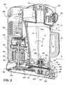
FIG. 2 is a cross-sectional view of a blending appliance having the blender jar ofFIG. 1 received therein; -
FIG. 3A is a fragmentary top perspective view of a base-portion of a blending appliance having an anti-rotational latch mechanism exploded away; -
FIG. 3B is a top perspective view of the base portion and anti-rotational latch mechanism ofFIG. 3A ; -
FIG. 3C is a top plan view of the base portion and anti-rotational latch mechanism ofFIG. 3B ; -
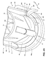
FIG. 4A is a fragmentary top perspective view of the blender jar ofFIG. 1 received within the blending appliance with the anti-rotational latch in a latch position; -
FIG. 4B is a fragmentary top perspective view of the blending appliance ofFIG. 4A having a portion of the housing removed; -
FIG. 5 is a fragmentary top perspective view of a blender jar with an anti-rotational latch mechanism in a latched position; and -
FIG. 6 is a top perspective view of the blender jar and anti-rotational latch mechanism ofFIG. 5 with the anti-rotational latch mechanism in an unlatched position. - Referring now to
FIG. 1 , thereference numeral 10 generally designates a blender jar having aside wall 12 which generally defines ablending cavity 14 accessible through an openupper end 16. The openupper end 16 includes aspout portion 18 and further has a generally teardrop shaped configuration T. Moving from the openupper end 16 of theblender jar 10 towards alower portion 20 of theblender jar 10, the configuration of theside wall 12 gradually changes and tapers from the generally teardrop shaped configuration T to a generally rectangular configuration R at thelower portion 20. Thus, theblending cavity 14 has a changing dual configuration from the openupper end 16 to thelower portion 20. Theside wall 12 further includes a plurality ofribs 22 which inwardly extend into theblending cavity 14 and taper from anupper portion 22A to alower portion 22B. The inwardly extendingribs 22, in conjunction with the varied configuration of theblending cavity 14, are adapted to reduce a bridging effect of blender contents during a blending procedure. The inwardly extendingribs 22 along with the configuration of theblending cavity 14 help to fold blender contents into a blending path for subsequent blending by a blade assembly. Ahandle member 24 extends outwardly from theside wall 12 for engagement by a user. As further shown inFIG. 1 , theblender jar 10 includes ajar base 26 which, in the embodiment ofFIG. 1 , is a generally circular dome shaped base having anengagement tab 30 extending outwardly therefrom. Theengagement tab 30 is generally defined by a rampedsurface 32 which culminates in a laterally extendingabutment surface 34. In use, theengagement tab 30 is adapted to couple to a latch mechanism of a blending appliance as further described below. - Referring now to
FIG. 2 , theblender jar 10 is shown being received within ablending appliance 100. Theblending appliance 100 includes ahousing 102 which comprises anupper housing member 104, amotor compartment 106, and abase portion 108. Theupper housing member 104 andbase portion 108 generally extend outwardly from thehousing 102 above and below themotor compartment 106. Thebase portion 108 includes asupport pad 110 such that ajar receiving portion 112 is defined between theupper housing member 104 and thebase portion 108 for receiving theblender jar 10 in a lateral or horizontal manner along a path as indicated by arrow A. Thus, as shown inFIG. 2 , theblender jar 10 is laterally received within thejar receiving portion 112 which is adjacent to themotor compartment 106. In this way, theblender jar 10 of the present disclosure is a low profile sidedrive blender appliance 100 which does not include a conventional stacked configuration of a blender jar over a motor housing and drive motor. In the embodiment shown inFIG. 2 , alid 114 is disposed over the openupper end 16 of theblender jar 10 and includes an aperture 116 which is aligned with afeed chute assembly 118 that is generally disposed through theupper housing member 104. Thus, when theblender jar 10 is horizontally received within the blenderjar receiving portion 112, thefeed chute assembly 118 is aligned with the aperture 116 of thelid 114 for introducing ingredients into theblender cavity 14. Theupper housing member 104 further includes auser interface 120 in the form of a rotary dial which is adapted to control various blending operations of theblending appliance 100. - As further shown in
FIG. 2 , theblending appliance 100 includes amotor 122 having adrive shaft 124 which is coupled to abelt drive system 130 at a lower end and a ductedfan 132 at an upper end. The ductedfan 132 may also be disposed below themotor 122 and is generally adapted to draw air into and exhaust air out of thehousing 102 throughvents housing 102. Themotor 122 is adapted to drive ablade assembly 140 disposed within theblending cavity 14 of theblender jar 10 when theblender jar 10 is fully received within thejar receiving portion 112 of theblending appliance 100. Themotor 122 drives theblade assembly 140 through thebelt drive system 130 and amagnetic coupling system 150 as further described below. As noted above, amagnetic coupler system 150 is used to drive theblade assembly 140 within theblender cavity 114 as powered by themotor 122.FIG. 2 illustrates abelt drive system 130 which is used to translate torque from themotor 122 to themagnetic coupler system 150. It is contemplated that any number of torque translating features may be used in place of thebelt drive system 130, so long as rotational power from themotor 122 is translated to theblade assembly 140. Themagnetic coupler system 150 includes an upper magnetic coupler M1 and a lower magnetic coupler M2. The lower magnetic coupler M2 is engaged with a belt 131 of thebelt drive system 130 for rotation therewith, as driven by themotor 122. - The lower magnetic coupler M2 is coupled to a
shaft 152 and is disposed within thebase portion 108 of the blendingappliance 100. The lower magnetic coupler M2 is disposed adjacent to thesupport pad 110 of thejar receiving portion 112. Thesupport pad 110 generally encapsulates the lower magnetic coupler M2 within thebase portion 108. The upper magnetic coupler M1 is disposed within thejar base 26 of theblender jar 10. The upper magnetic coupler M1, as coupled to theblender jar 10, is removable from the blendingappliance 100 when theblender jar 10 is removed from thejar receiving portion 112. The upper magnetic coupler M1 is coupled to ashaft 154 which is further coupled to theblade assembly 140 which is fully disposed within a receptacle portion orblender cavity 14 of theblender jar 10. Themagnetic coupling system 150 magnetically couples theblender jar 10 to thebase portion 108 of the blendingappliance 100 through magnetic attraction generated between upper and lower magnetic couplers M1, M2. As shown in the embodiment ofFIG. 2 , the upper and lower magnetic couplers M1, M2, have a generally circular or disc-shaped configuration at a prescribed diameter, such that theblender jar 10 will properly seat on thesupport pad 110 due to the magnetic forces generated between the upper and lower magnetic couplers M1, M2. In assembly and in use, themotor 122 drives the drivebelt drive system 130, as described above, thereby driving theshaft 152 in a direction as indicated by arrow R1. Due to the magnetic attraction and magnetic coupling of the lower magnetic coupler M2 to the upper magnetic coupler M1, the upper magnetic coupler M1 also rotates along the rotational direction as indicated by arrow R1. In this way, the upper and lower magnetic couplers M1, M2 drive theblade assembly 140 disposed within theblender cavity 14 of theblender jar 10 through a magnetic torque coupling, rather than a conventional mechanical coupling. - The upper and lower magnetic couplers M1, M2 may be comprised of a magnetic material or may be in the form of a polymeric housing which includes a plurality of magnetic elements or solid
magnetic rings - As described above, the
magnetic coupling system 150 of the blendingappliance 100 serves to translate torque to theblade assembly 140 without a conventional mechanical coupling between theblade assembly 140 and a gear mechanism operably coupled to themotor 122. Without this mechanical coupling, theblender jar 10 can be horizontally received within thejar receiving portion 112 along a path as indicated by arrow A, as the generally planar lower portion of thebase 26 of thejar 10 is adapted to slide unimpeded along thesupport pad 110 disposed on an upper portion of thebase portion 108. The magnetic coupling between the upper and lower coupling mechanisms M1, M2 of themagnetic coupling system 150 may cause theblender jar 10 to move on theplanar support pad 110, such that the upper and lower magnetic couplers M1, M2 can become misaligned, thereby disrupting the translation of torque to theblade assembly 140. To counter this effect and resist rotational movement of theblender jar 10, the blendingappliance 100 of the present disclosure includes jar retaining mechanisms as further described below. - Referring now to
FIGS. 3A-3C , thebase portion 108 of the blendingappliance 100 is shown having arear portion 108b and afront portion 108a. Therear portion 108b includes anaperture 170 through which thedrive shaft 124 of themotor 122 downwardly extends to thebelt drive system 130 as shown inFIG. 2 . Thebase portion 108 further includes mountingfeatures 172 disposed about theaperture 170 for coupling thebase portion 108 to themotor housing 106, also shown inFIG. 2 . Thesupport pad 110 is disposed on an upper portion of thefront portion 108a of thebase portion 108. Thesupport pad 110 includes alip 174 which surrounds a rear portion of thesupport pad 110. Thelip 174 further includes raised abutment features 176 which together with thelip 174 serve to properly locate theblender jar 10 as received within thejar receiving portion 112. As shown inFIG. 3A , ajar retainer mechanism 180 includes an articulatingarm 182 which is coupled to thebase portion 108 at anaperture 184 via afastener 186. In this way, the articulatingarm 182 is adapted to pivot about a latch axis LA between a disengaged position D and an engaged position E along a path as indicated by arrow B. Abiasing mechanism 188, shown in the form of a coil spring inFIG. 3A , includes first andsecond arms abutment portion 194 on the articulatingarm 182 and a mountingfeature 172 disposed adjacent toaperture 184. In this way, thebiasing mechanism 188 biases the articulatingarm 182 towards the engaged position E.The articulating arm 182 includes alatch member 200 at a first end having a rampedouter surface 202 and a generallyplanar abutment surface 204. Thelatch member 200 is supported on the articulatingarm 182 by alatch support portion 206. A locatingfeature 208 is further disposed on thelatch support portion 206 and generally engages acradle feature 210 disposed on thebase member 108 adjacent thelip 174. On an opposite second end of the articulatingarm 182 relative to thelatch member 200, apush member 212 is disposed which is adapted to push or displace theblender jar 10 outwardly as thelatch member 200 and articulatingarm 182 are moved to the disengaged position D. Thus, thelatch member 200 and thepush member 212 are disposed on opposite sides of the latch axis LA, and therefore move in an inverse manner relative to one another away from and towards theblender jar 10 as received on thesupport pad 110. - Referring now to
FIGS. 3B and3C , thejar retainer mechanism 180 is shown having the articulatingarm 182 pivotally coupled to thebase portion 108 viafastener 186, such that the articulatingarm 182 pivots at the latch axis or pivot point LA. As noted above, with reference toFIG. 2 , theblenderjar 10 includes ajar base 26. As theblenderjar 10 is laterally received on thesupport pad 110, thejar base 26 of theblender jar 10 will engage the rampedportion 202 oflatch member 200, thereby urging the articulatingarm 182 towards the disengaged position D. The movement of the articulatingarm 182 to the disengaged position D is further advanced by the rampedportion 32 of theengagement tab 30 disposed on thebase portion 26 of theblender jar 10 as shown inFIG. 1 . As thejar assembly 10 moves further along the path as indicated by arrow A into full engagement with thehousing 102 in thejar receiving portion 112, theengagement tab 30 will slide past aninnermost portion 205 of thelatch member 200, such that the articulatingarm 182, as biased by thebiasing mechanism 188, will snap-fit into the engaged position E, whereinabutment surface 34 of theengagement tab 30 is positioned to engageabutment portion 204 of thelatch member 200 in an abutting relationship. As noted above, themagnetic coupling system 150, shown inFIG. 2 , is adapted to rotate theblade assembly 140 in a direction as indicated by arrow R1. Thus, as the contents of theblender jar 10 impart a resistance force on theblade assembly 140 along the rotational path indicated by arrow R1, theblender jar 10 will have a tendency to rotate in the direction as indicated by arrow R1 inFIG. 3C . When this type of rotation of theblender jar 10 occurs,abutment surface 34 ofengagement tab 30 will abut generallyplanar abutment portion 204 of thelatch member 200, such that thelatch member 200 will retain theblender jar 10 in place for proper torque translation from themagnetic coupling system 150 to theblade assembly 140. As further shown inFIG. 3C , thepush member 212 moves along a path as indicated by arrow C as the articulatingarm 182 moves to the disengaged position D. In this way, thepush member 212 pushes theblender jar 10 outwardly from its fully received position on thesupport pad 110. In this way, and with reference toFIG. 2 , theblender jar 10 is vertically retained in thejar receiving portion 112 by thesupport pad 110 of thebase portion 108 of thehousing 102 at a lower end, and further retained by theupper housing member 104 as disposed over theopen end 16 andlid 114 of theblender jar 10. This vertical retainment of theblender jar 10 in thejar receiving portion 112 is further aided by thejar retainer mechanism 180, which resists against rotational and lateral movement of theblender jar 10 during a blending procedure. - Referring now to
FIGS. 4A and4B , theblender jar 10 is shown fully received within the blenderjar receiving portion 112 of thehousing 102 of the blendingappliance 100. As properly located for use in a blending procedure on thesupport pad 110, theblender jar 10 has theengagement tab 30, disposed outwardly from thejar base 26 of theblender jar 10 in engagement with thelatch member 200. Specifically,abutment surface 34 of theengagement tab 30 is abuttingly engaged withabutment portion 204 of thelatch member 200 when the articulatingarm 182 is in the engaged position E. In this way, thejar retainer mechanism 180 retains thejar 10 against rotational forces imparted on theblender jar 10 in a direction as indicated by arrow R1 during a blending procedure. As specifically shown inFIG. 4B ,push member 212, disposed on an opposite end of the articulatingarm 182 relative to thelatch member 200, is in abutting engagement with thejar base 26 of theblender jar 10 when the articulatingarm 182 is in the engaged position E and theblender jar 10 is fully received within thehousing 102. As the articulatingarm 182 moves to the disengaged position D along the path as indicated by arrow B, thepush member 212 will inversely move to impart an outward lateral force in the direction as indicated by arrow C on thejar base 26 of theblender jar 10 to aid in the ejection of theblender jar 10 from thejar receiving portion 112. Further, as biased by the biasingmember 188 to the engaged position E, the articulatingarm 182 imparts a constant force on thebase portion 26 andengagement tab 30 of theblender jar 10. Again, the rampedsurface 32 of theengagement tab 30 allows theblender jar 10 to slide around the roundedinnermost portion 205 of thelatch 200, for a snap-fit engagement of thelatch member 200 with theengagement tab 30 without the need for the user to separately move the articulatingarm 182 to the disengaged position D. Further, this snap-fit engagement provides the user with tactile feedback that theblender jar 10 is properly received within thejar receiving portion 112 and is properly seated on thesupport pad 110 for consistent and efficient translation of torque through themagnetic coupling system 150. - Referring now to
FIG. 5 , thejar retainer mechanism 180 is shown with the articulatingarm 182 in the engaged position E, such that thelatch member 200 is engaged with theengagement tab 30 in a manner as described above. When a user wishes to release theblender jar 10 from theretainer mechanism 180, the user will generally engage the rampedsurface 202 of thelatch member 200 to pivot the articulatingarm 182 towards the disengaged position D along a path as indicated by arrow B. In this way, thelatch member 200 moves laterally from the engaged position E to release theblender jar 10. With reference toFIG. 6 , thejar retainer mechanism 180 is shown with the articulatingarm 182 pivoted to the disengaged position D along the path as indicated by arrow B. As shown inFIG. 6 , thelatch member 200 of the articulatingarm 182 is laterally spaced apart from theengagement tab 30 disposed on thejar base 26 of theblender jar 10. Further, as noted above, when moved to the disengaged position D, thepush member 212, shown inFIG. 4B , will urge theblender jar 10 at thejar base 26 outwardly in a direction as indicated by arrow C. In this way, thejar retainer mechanism 180 serves to retain theblender jar 10 in an in-use position when the articulatingarm 182 is in the engaged position E, and further aids in the release of theblender jar 10 from thejar receiving portion 112 via thepush member 212 when the articulatingarm 182 is moved to the disengaged position D.
Claims (15)
- A jar retainer mechanism (180) for a blending appliance (100), comprising:a housing (102) having an upper housing member (104) and a base portion (108) with a jar receiving portion (112) defined therebetween;a blender jar (10) configured to be laterally received in the jar receiving portion (112), the blender jar (10) having an engagement tab (30) disposed on a jar base portion (26); andan articulating arm (182) coupled to the base portion (108) of the housing (102) and operable between engaged and disengaged positions, wherein the articulating arm (182) includes a latch member (200) configured to engage the engagement tab (30) of the blender jar (10) when the articulating arm (182) is in the engaged position.
- The jar retainer mechanism (180) of claim 1, wherein the engagement tab (30) includes a ramped surface (32) and an abutment surface (34).
- The jar retainer mechanism (180) of claim 2, wherein the latch member (200) includes an abutment portion (204) configured to be in abutting engagement with the abutment surface (34) of the engagement tab (30) when the blender jar (10) is received in the jar receiving portion (112).
- The jar retainer mechanism (180) of any one of claims 1-3, further comprising:a biasing mechanism (188) coupled to the articulating arm (182) and configured to bias the articulating arm (182) towards the engaged position.
- The jar retainer mechanism (180) of claim 4, wherein the biasing mechanism (188) comprises a coil spring (188) further coupled to the base portion (108) of the housing (102).
- The jar retainer mechanism (180) of any one of claims 1-5, wherein the blender jar (10) includes an open upper end (16) having a first configuration (T) and a lower portion (20) having a second configuration (R), and further wherein the second configuration (R) is varied relative to the first configuration (T).
- The jar retainer mechanism (180) of claim 6, wherein the first configuration (T) comprises a teardrop shape (T), and the second configuration (R) comprises a rectangular shape (R).
- The jar retainer mechanism (180) of any one of claims 1-7, further comprising:a push member (212) disposed on an opposite end of the articulating arm (182) relative to the latch member (200), the push member (212) configured to displace the blender jar (10) when the articulating arm (182) is moved towards the disengaged position.
- The jar retainer mechanism (180) of any one of claims 1-8, wherein the engagement tab (30) extends outwardly from a jar base portion (26) of the blender jar (10).
- The jar retainer mechanism (180) of any one of claims 1-2, wherein the ramped surface (32) is configured to engage the latch member (20) as the blender jar (10) is laterally received within the housing (102), and further wherein the engagement of the ramped surface (32) of the engagement tab (30) and the latch member (200) urges the articulating arm (182) towards the disengaged position.
- The jar retainer mechanism (180) of any one of claims 4-5, wherein the biasing mechanism (188) provides for a snap-fit engagement between the articulating arm (182) and the engagement tab (30).
- The jar retainer mechanism (180) of claim 8, wherein the push member (212) is configured to laterally displace the blender jar (10) away from the housing (102) as the articulating arm (182) is moved towards the disengaged position.
- The jar retainer mechanism (180) of claim 12, wherein the latch member (200) and the push member (212) are disposed on opposite sides of the articulating arm (182) with a pivot axis LA of the articulating arm (182) disposed therebetween.
- The jar retainer mechanism (180) of any one of claims 1-13, further comprising:a magnetic coupling system (150) having upper and lower magnetic couplers M1,M2, wherein the upper magnetic coupler M1 is disposed in the jar base portion (26) of the blender jar (10) and the lower magnetic coupler M2 is disposed in the base portion (108) of the housing (102).
- The jar retainer mechanism (180) of claim 1, wherein the blending jar (10) is vertically retained by upper housing member (104) at an open upper end (16) of the blender jar (10) and further retained by the base portion (108) of the blender jar (10) when the blender jar (10) is received in the jar receiving portion (112) of the housing (102), and further wherein the blender jar (10) is rotationally retained by the engagement of the engagement tab (30) of the blender jar (10) and the latch member (200) of the articulating arm (182) when the articulating arm (182) is in the engaged position and the blender jar (10) is received in the jar receiving portion (112).
Applications Claiming Priority (1)
| Application Number | Priority Date | Filing Date | Title |
|---|---|---|---|
| US14/208,234 US9763542B2 (en) | 2014-03-13 | 2014-03-13 | Anti-rotational latch for a blending appliance |
Publications (1)
| Publication Number | Publication Date |
|---|---|
| EP2921090A1 true EP2921090A1 (en) | 2015-09-23 |
Family
ID=53008259
Family Applications (1)
| Application Number | Title | Priority Date | Filing Date |
|---|---|---|---|
| EP15159050.2A Withdrawn EP2921090A1 (en) | 2014-03-13 | 2015-03-13 | Anti-rotational latch for a blending appliance |
Country Status (3)
| Country | Link |
|---|---|
| US (1) | US9763542B2 (en) |
| EP (1) | EP2921090A1 (en) |
| AU (1) | AU2015201252A1 (en) |
Cited By (1)
| Publication number | Priority date | Publication date | Assignee | Title |
|---|---|---|---|---|
| EP3146875A1 (en) * | 2015-09-28 | 2017-03-29 | Wen-Ching Lee | Food blender with safety protection mechanism |
Families Citing this family (3)
| Publication number | Priority date | Publication date | Assignee | Title |
|---|---|---|---|---|
| US9555384B2 (en) * | 2013-10-25 | 2017-01-31 | Whirlpool Corporation | Blender assembly |
| FR3111059B1 (en) * | 2020-06-05 | 2022-07-22 | Seb Sa | System for locking a bowl on a motorized base of a food processor |
| EP4445815B1 (en) * | 2023-04-14 | 2025-10-29 | Suntek Industries (Hong Kong) Company Limited | Cooking pot locking mechanism and food processor comprising the cooking pot locking mechanism |
Citations (1)
| Publication number | Priority date | Publication date | Assignee | Title |
|---|---|---|---|---|
| US4174073A (en) * | 1978-07-17 | 1979-11-13 | General Electric Company | Multi container interlocked food machine with a safety switch for each container |
Family Cites Families (13)
| Publication number | Priority date | Publication date | Assignee | Title |
|---|---|---|---|---|
| US4653519A (en) | 1985-07-09 | 1987-03-31 | Ryder International Corporation | Rinsing apparatus for contact lens cleaning system |
| BE1007431A3 (en) | 1993-08-04 | 1995-06-13 | Philips Electronics Nv | Food with a lid lock with centrifugal organ. |
| JPH08508669A (en) | 1994-02-07 | 1996-09-17 | フィリップス エレクトロニクス ネムローゼ フェンノートシャップ | Kitchen equipment with protected rotating bowl |
| FR2759273B1 (en) | 1997-02-11 | 1999-04-23 | Moulinex Sa | KITCHEN ROBOT WITH TWO RECEIVING OUTPUTS OF REMOVABLE WORK ACCESSORIES |
| US6095677A (en) | 1999-01-12 | 2000-08-01 | Island Oasis Frozen Cocktail Co., Inc. | Magnetic drive blender |
| JP2002534953A (en) | 1999-01-12 | 2002-10-15 | アイランド オアシス フローズン カクテル シーオー インク | Processing equipment including magnetic drive |
| US6793167B2 (en) | 1999-01-12 | 2004-09-21 | Island Oasis Cocktail Company, Inc. | Food processing apparatus including magnetic drive |
| DE10016294A1 (en) | 2000-03-31 | 2001-10-04 | Bsh Bosch Siemens Hausgeraete | Food processor |
| US6748853B1 (en) | 2000-09-13 | 2004-06-15 | Hamilton Beach/Proctor-Silex, Inc. | Food processing machine |
| US6632013B2 (en) | 2001-04-02 | 2003-10-14 | Sunbeam Products, Inc. | Blender with food processor capabilities |
| US6609821B2 (en) | 2001-04-13 | 2003-08-26 | Sunbeam Products, Inc. | Blender base with food processor capabilities |
| US8109668B2 (en) | 2007-03-01 | 2012-02-07 | Hamilton Beach Brands, Inc. | Blender having an invertable jar for compact storage |
| US7950842B2 (en) | 2007-03-05 | 2011-05-31 | Hamilton Beach Brands, Inc. | Durability monitoring and improvement of a blender |
-
2014
- 2014-03-13 US US14/208,234 patent/US9763542B2/en not_active Expired - Fee Related
-
2015
- 2015-03-11 AU AU2015201252A patent/AU2015201252A1/en not_active Abandoned
- 2015-03-13 EP EP15159050.2A patent/EP2921090A1/en not_active Withdrawn
Patent Citations (1)
| Publication number | Priority date | Publication date | Assignee | Title |
|---|---|---|---|---|
| US4174073A (en) * | 1978-07-17 | 1979-11-13 | General Electric Company | Multi container interlocked food machine with a safety switch for each container |
Cited By (1)
| Publication number | Priority date | Publication date | Assignee | Title |
|---|---|---|---|---|
| EP3146875A1 (en) * | 2015-09-28 | 2017-03-29 | Wen-Ching Lee | Food blender with safety protection mechanism |
Also Published As
| Publication number | Publication date |
|---|---|
| US20150257601A1 (en) | 2015-09-17 |
| AU2015201252A1 (en) | 2015-10-01 |
| US9763542B2 (en) | 2017-09-19 |
Similar Documents
| Publication | Publication Date | Title |
|---|---|---|
| CN110799076B (en) | Mixer with safety mechanism | |
| US10299629B2 (en) | Translatable interlocking mechanism for a blending system | |
| US12070159B2 (en) | Food processing apparatus and method | |
| EP3270751B1 (en) | Food processor | |
| KR102406964B1 (en) | Grinder attachment for blender system | |
| CN110198651A (en) | Food processing cover | |
| CN108697265A (en) | Cooking apparatus | |
| US9763542B2 (en) | Anti-rotational latch for a blending appliance | |
| JP2019535432A (en) | Blender connection mechanism | |
| EP2538798A2 (en) | Cup holding assembly for a food mixing machine | |
| JP2018507052A (en) | Food processor system | |
| CN110313817A (en) | Pressure culinary art and the cooking apparatus without pressure culinary art can be achieved | |
| CN110313816A (en) | Pressure culinary art and the cooking apparatus without pressure culinary art can be achieved | |
| KR101717011B1 (en) | Mixer composite apparatus | |
| US9468339B2 (en) | Low profile side drive blending appliance | |
| EP4183299A1 (en) | A kitchen appliance | |
| CN115486733A (en) | Electric enclosures for cooking and preparation appliances | |
| KR200485526Y1 (en) | Cooking machinery which is controlled by magnetic material | |
| CN211582585U (en) | Cooking utensil | |
| EP4429529B1 (en) | A kitchen appliance | |
| CN222828414U (en) | Cooking utensils | |
| CN211533878U (en) | Cooking utensil | |
| CN217723220U (en) | Mixer | |
| US20240324821A1 (en) | Kitchen appliance | |
| JP2003512118A (en) | Household device with spring suspended appliance |
Legal Events
| Date | Code | Title | Description |
|---|---|---|---|
| PUAI | Public reference made under article 153(3) epc to a published international application that has entered the european phase |
Free format text: ORIGINAL CODE: 0009012 |
|
| AK | Designated contracting states |
Kind code of ref document: A1 Designated state(s): AL AT BE BG CH CY CZ DE DK EE ES FI FR GB GR HR HU IE IS IT LI LT LU LV MC MK MT NL NO PL PT RO RS SE SI SK SM TR |
|
| AX | Request for extension of the european patent |
Extension state: BA ME |
|
| 17P | Request for examination filed |
Effective date: 20160323 |
|
| RBV | Designated contracting states (corrected) |
Designated state(s): AL AT BE BG CH CY CZ DE DK EE ES FI FR GB GR HR HU IE IS IT LI LT LU LV MC MK MT NL NO PL PT RO RS SE SI SK SM TR |
|
| STAA | Information on the status of an ep patent application or granted ep patent |
Free format text: STATUS: EXAMINATION IS IN PROGRESS |
|
| 17Q | First examination report despatched |
Effective date: 20180723 |
|
| STAA | Information on the status of an ep patent application or granted ep patent |
Free format text: STATUS: THE APPLICATION IS DEEMED TO BE WITHDRAWN |
|
| 18D | Application deemed to be withdrawn |
Effective date: 20181204 |