EP2920801B1 - Contact system - Google Patents
Contact system Download PDFInfo
- Publication number
- EP2920801B1 EP2920801B1 EP13789779.9A EP13789779A EP2920801B1 EP 2920801 B1 EP2920801 B1 EP 2920801B1 EP 13789779 A EP13789779 A EP 13789779A EP 2920801 B1 EP2920801 B1 EP 2920801B1
- Authority
- EP
- European Patent Office
- Prior art keywords
- contact
- finger
- deflector
- arcing
- switching device
- Prior art date
- Legal status (The legal status is an assumption and is not a legal conclusion. Google has not performed a legal analysis and makes no representation as to the accuracy of the status listed.)
- Active
Links
Images



Classifications
-
- H—ELECTRICITY
- H01—ELECTRIC ELEMENTS
- H01H—ELECTRIC SWITCHES; RELAYS; SELECTORS; EMERGENCY PROTECTIVE DEVICES
- H01H1/00—Contacts
- H01H1/12—Contacts characterised by the manner in which co-operating contacts engage
- H01H1/36—Contacts characterised by the manner in which co-operating contacts engage by sliding
- H01H1/38—Plug-and-socket contacts
- H01H1/385—Contact arrangements for high voltage gas blast circuit breakers
Definitions
- the invention relates to the field of medium and high voltage switching technologies and concerns an electrical switching device, a contact arrangement for the electrical switching device and a method for closing the electrical switching system according to the independent claims, particularly for a use as an earthing switch, fast-acting earthing switch, disconnector, combined disconnector and earthing switch, load break switch, circuit breaker or generator circuit breaker, in power transmission or distribution systems.
- Electrical switching devices are well known in the field of medium and high voltage switching applications. They are e.g. used for interrupting a current when an electrical fault occurs.
- circuit breakers have the task of opening contacts and keeping them far apart from one another in order to avoid a current flow, even in case of high electrical potential originating from the electrical fault itself.
- medium voltage refers to voltages from 1 kV to 72.5 kV
- high voltage refers to voltages higher than 72.5 kV.
- the electrical switching devices may have to be able to carry high nominal currents of 5000 A to 6300 A and to switch very high short circuit currents of 63 kA to 80 kA at very high voltages of 550 kV to 1200 kV.
- the electrical switching devices of today require many so-called nominal contact fingers for the nominal current.
- the current When disconnecting (opening) a nominal or short circuit current within the electrical switching devices, the current commutates from nominal contacts of the electrical switching device to its arcing contacts.
- the arcing contacts are connected. They normally comprise as a first arcing contact arcing contact fingers arranged around the longitudinal axis of the electrical switching device in a so-called arcing finger cage and, as a second arcing contact, a rod which is driven into the finger cage.
- the opening and closing processes of the nominal and the arcing contacts have to be carried out with a predefined speed, according to the specification of the electrical switching device.
- the impact force acting on the arcing contact fingers depends on the closing speed of the rod.
- a high contact speed is desired because it improves the performance of the electrical switching device when applying controlled switching in the sense that the switching device is closed or opened as accurate as possible in the instant of e.g. voltage or current zero-crossing.
- the arcing contact fingers may experience a permanent deformation. For example, they may be deformed radially outward with respect to the longitudinal axis. A contact force between the arcing contact finger and the second arcing contact has to be high enough to ensure a good electrical contact. Eventually, requirements regarding the contact force are not met anymore because of the deformation.
- EP 0 951 038 A1 discloses an arcing contact arrangement in a generator circuit breaker having a support body for arcing contact fingers.
- an electrical switching device having a longitudinal axis and comprising at least one contact arrangement.
- the contact arrangement comprises a first contact and a mating second contact, wherein the first contact comprises at least one contact finger.
- the electrical switching device further comprises a deflector elastically deflecting the at least one contact finger in a radial direction away from the axis prior to or while closing the electrical switching device.
- the deflector is movable parallel to the longitudinal axis z between a first position corresponding to a pre-deflection position of the contact finger, in which the contact finger is elastically deflected by the deflector radially outward with respect to the longitudinal axis z, when the electrical switching device is in an opened configuration, and a second position corresponding to an end position of the second arcing contact, in which the deflector does not deflect the contact finger, when the electrical switching device is in a closed configuration, and the deflector is adapted to be moved from the first position into the second position by the second arcing contact when the electrical switching device is being closed.
- the advantage of designing the contact arrangement to have a deflector elastically deflecting the contact finger in the way mentioned above is that the impact stress is diminished while the required contact force between the two contacts is maintained.
- the at least one contact arrangement is or comprises an arcing contact arrangement
- the first contact is or comprises a first arcing contact comprising at least one arcing contact finger
- the mating second contact is or comprises a mating second arcing contact.
- at least one of the arcing contacts is movable parallel to the longitudinal axis and cooperates with the other arcing contact.
- the at least one contact arrangement is or comprises a nominal contact arrangement
- the first contact is or comprises a first nominal contact comprising a plurality of nominal contact fingers and forming a finger cage concentric with respect to the longitudinal axis
- the mating second contact is or comprises a mating second nominal contact.
- at least one of the nominal contacts is movable parallel to the longitudinal axis and cooperates with the other nominal contact.
- the invention also relates to a contact arrangement for an electrical switching device as disclosed above.
- the contact arrangement has a longitudinal axis and comprises at least one contact finger.
- a deflector is provided, which elastically deflects the contact finger in a radial direction away from the axis prior to or while closing the electrical switching device.
- the contact arrangement is further characterized by the features of any of the dependent claims.
- the contact arrangement is or comprises an arcing contact arrangement and the contact finger is or comprises an arcing contact finger, and/or the contact arrangement is or comprises a nominal contact arrangement and the contact finger is or comprises a nominal contact finger.
- a third aspect of the invention concerns a method for closing a contact arrangement according to the second aspect of the invention of an electrical switching device according to the first aspect of the invention.
- the method comprises the steps of deflecting the contact finger radially outward by means of the deflector and connecting the second contact with the deflected first contact.
- the advantage of closing the electrical switching device in the way is that a reduction of the mechanical strain exerted on the contact fingers is attained by pre-opening the contact fingers before their first impact with the second contact. By this, the contact fingers are subjected to less mechanical stress and consequently their lifetime is prolonged.
- the invention is described for the example of a high voltage circuit breaker having nominal contacts and arcing contacts, but the principles described in the following also apply for the usage of the invention in other switching devices, e.g. of the type mentioned at the beginning, such as in an earthing switch, fast-acting earthing switch, disconnector, combined disconnector and earthing switch, load break switch, circuit breaker or generator circuit breaker, and generally in any switch for high voltage or medium voltage.
- the invention is fully applicable in switches having an arcing contact arrangement solely, a nominal contact arrangement solely, or both an arcing contact system and a nominal contact system.
- An arcing contact arrangement shall encompass a first arcing contact comprising at least one arcing contact finger 4a, and a mating second arcing contact 4b, both being movable relative to one another.
- a nominal contact arrangement shall encompass a first nominal contact comprising a plurality of nominal contact fingers 3a, and a mating second arcing contact 3b, both being movable relative to one another.
- Fig. 1 shows a partial sectional view of a simplified basic embodiment of a high voltage circuit breaker 1 in a closed configuration.
- "partial section view” means that only the upper half of a section of the circuit breaker is shown, for reasons of clarity.
- the device is rotationally symmetric about a longitudinal axis z. Only the elements of the circuit breaker 1 which are related to the present invention are described in the following. Other elements present in the figures are not relevant for understanding the invention and are known by the skilled person in high voltage electrical engineering.
- a "closed configuration” as used herein means that the nominal contacts and/or the arcing contacts of the circuit breaker are closed. Particularly, a closed configuration is interpreted as a motionless arrangement of said contacts.
- the term “being closed” or “closing process” refer to a moving state of the contact or contacts.
- an "opened configuration” as used herein means that the nominal contacts and/or the arcing contacts of the circuit breaker are opened. Particularly, an opened configuration is interpreted as a motionless arrangement of said contacts.
- the term “being opened” or “opening process” refer to a moving state of the contact or contacts.
- the circuit breaker 1 comprises a chamber enclosed by a shell or enclosure 5 which normally is cylindrical around the longitudinal axis z. It further comprises a nominal contact arrangement formed by a first nominal contact comprising a plurality of contact fingers 3a, of which only one is shown here for reasons of clarity.
- the nominal contact arrangement is formed as a finger cage around the longitudinal axis z.
- a shielding 9 can be arranged around the finger cage.
- the nominal contact arrangement further comprises a second mating contact 3b which normally is a metal tube.
- the contact fingers 3a and the second contact 3b are movable relatively to one other from the closed configuration shown in Fig. 1 , in which they are in electrical contact with one another, into an opened configuration, in which they are apart from one another, and vice versa. It is also possible that only one of the contacts 3a, 3b moves parallel to the longitudinal axis z and the other contact 3b, 3a is stationary along the longitudinal axis z.
- the contact fingers 3a are attached to or can be a part of a finger support 2, particularly a metal support cylinder.
- the circuit breaker 1 furthermore comprises an arcing contact arrangement formed by a first arcing contact 4a and a second arcing contact 4b.
- the first nominal contact and the first arcing contact 4a may be movable with respect to one another, as well as the second nominal contact and the second arcing contact 4b.
- the first nominal contact and the first arcing contact 4a are not movable relatively to one another.
- the second nominal contact 3b and the second arcing contact 4b are not movable with respect to one another.
- the latter embodiment it is assumed that only the second nominal contact 3b and the second arcing contact 4b are movable and the finger cage and the first arcing contact 4a are stationary along the z-axis.
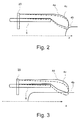
- Fig. 2 shows a sectional view of an arcing contact finger 4a of the first arcing contact with a first comparative embodiment of a deflector 6 in an idle position, in other words in an opened configuration of the electrical switching device 1.
- the deflector 6 is arranged radially between a longitudinal axis z of the electrical switching device 1 and the arcing contact finger 4a.
- the deflector 6 is a tube and has such a diameter that the arcing contact finger 4a is deflected outward with respect to the longitudinal axis z by not more than 0.05 cm. In other words an inner diameter of the arcing contact finger cage increases up to 0.1 cm.
- the arcing contact finger 4a is pre-opened by the deflector 6.
- the arcing contact finger 4a normally has a curvature towards the longitudinal axis z at its free end, also called tulip, as can be seen in the figures.
- the arcing contacts 4a, 4b are shown in Fig. 2 in an opened configuration and in Fig. 3 in a closed configuration.
- the arcing contact finger is shown with dashed lines and denoted by the reference numeral 4c in a non-deflected position as it would be arranged without the deflector 6. This is assumed for the subsequent embodiments, as well, but the corresponding illustration is not shown in these embodiments because of clarity reasons.
- Fig. 3 shows the sectional view of the arcing contact finger 4d of the first arcing contact of Fig. 2 with the deflector 6 in the closed configuration of the electrical switching device 1.
- the deflector 6 has substantially no more contact to the arcing contact finger 4d, as the second arcing contact 4b now elastically deflects the arcing contact finger radially outward with respect to the longitudinal axis z.
- a first deflection of the arcing contact finger 4a is caused by the deflector 6, subsequently called pre-deflection
- a further deflection of the arcing contact finger 4d is caused by the second arcing contact 4b, subsequently called final deflection.
- the electrical switching device 1 further comprises a finger support 20 carrying the at least one contact finger 4a.
- the deflector 6 is fixedly attached to the finger support 20 in a first position corresponding to the pre-deflection position of the arcing contact finger 4a, as shown in Fig. 2 .
- the arcing contact finger 4c is positioned as pre-deflected arcing contact finger 4a in the opened configuration of the electrical switching device 1 and it is positioned in the final deflection position 4d in the closed configuration of the electrical switching device 1.
- the deflector 6 has a higher stiffness than the arcing contact finger 4a. By this it is made sure that the deflector deflects the arcing contact finger 4a and not vice versa.
- the stiffness of the deflector 6 is chosen such that the highest deflection effect is attained, in other words such that the bending of the deflector 6 itself is minimal.
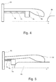
- Fig. 4 shows a sectional side view of an arcing contact finger 4a of the first arcing contact with a second embodiment of a deflector 7a in the opened configuration of the electrical switching device 1.
- the deflector 7a is also arranged between the longitudinal axis z and the arcing contact finger 4a, like in case of the first comparative embodiment of Fig. 2 .
- a spring 7b is provided, which connects the finger support 20 carrying the at least one contact finger 4a and the deflector 7a.
- the deflector 7a is movable parallel to the longitudinal axis z between a first position and a second position.
- the first position corresponds to a pre-deflection position of the arcing contact finger 4a, in which the deflector 7a abuts against the arcing contact finger 4a, particularly against a tulip of the arcing contact finger 4a, and elastically deflects the arcing contact finger 4a radially outward with respect to the longitudinal axis z when the electrical switching device 1 is in an opened configuration.
- the second position corresponds to an end position of the second arcing contact 4b in the closed configuration of the electrical switching device 1. In other words, after the second arcing contact 4b has started entering the arcing finger cage, the arcing contact finger 4a is further deflected until it reaches its final deflection position, being denoted by 4d in this position.
- the deflector 7a has substantially no more contact to the arcing contact 4a.
- the second arcing contact 4b is further pushed in the direction opposite to the arrow z it eventually reaches the deflector 7a and pushes it until the second arcing contact 4b has reached its end position inside the arcing finger cage.
- the deflector 7a does not deflect the arcing contact finger 4d.
- the arcing contact finger 4d is only deflected by the second arcing contact 4b.
- the deflector 7a is adapted to be moved from the first position into the second position by the second arcing contact 4b when the electrical switching device 1 is being closed.
- the deflector 7a is adapted to be moved from the second position into the first position by the spring 7b when the electrical switching device 1 is being opened and reaches the first position before the second arcing contact 4b has left the arcing finger cage.
- This embodiment of the deflector 7a in connection with the spring 7b has a similar effect like the comparative embodiment of the fixed deflector 6 of Fig. 2 and 3 , as the arcing contact finger 4a is always kept in a pre-deflected state in the opened configuration of the electrical switching device 1.
- the deflector 7a is star-shaped and advantageously comprises Teflon or is made of Teflon.
- the advantage of the star shape is that an extinguishing medium inside the switching device 1, which cools down the electric arc forming between the two arcing contacts 4a, 4b when closing or opening the electrical switching device 1, can flow faster through the deflector 7a and thus it can escape through the "channels" formed between the star teeth of the deflector 7a, which in this embodiment has a larger opening.
- the deflector 7a is guided on an inner surface of the arcing contact finger 4a.
- the inner surface denotes a surface facing the longitudinal axis z.
- the radial dimensions of the deflector 7a are chosen in such a way that its edge or edges opposed to the edge or edges sliding on the inner surface of the arcing contact finger 4a are closer to the longitudinal axis z than the lowermost extremity of the free end of the tulip of the arcing contact finger 4a.
- the term "lower” or “lowermost” is interpreted as "closer” or "closest” to the longitudinal axis z.
- the second arcing contact 4b which is shifted parallel to the longitudinal axis z in a contrary direction to the arrow of the axis z, is capable of pushing the deflector 7a back towards the finger support 20.
- the diameter of the deflector 7a is chosen to have such a value that the deflector 7a can move freely, in particular parallel to the longitudinal axis z, after a first contact of the first and the second arcing contacts 4a, 4b while closing the electrical switching device 1 or until a last contact of the first and the second arcing contacts 4a, 4b while opening the electrical switching device 1 respectively.
- the spring 7b is arranged inside a protecting tube 7c, in particular inside a hollow protecting tube 7c, which is fixedly attached to the deflector 7a.
- the protecting tube 7c moves along with the deflector 7a when the deflector 7a is shifted between the first and the second positions.
- the deflector 7a can be supported by the finger support 20 in order to make sure that the finger support 20 moves substantially parallel to the longitudinal axis z.
- a support element not shown here is movably supported by the finger support 20.
- the support element may be shifted back and forth through a hole in the finger support 20.
- the deflector 7a has a higher stiffness than the arcing contact finger 4a. By this it is made sure that the deflector 7c deflects the arcing contact finger 4a and not vice versa.
- the stiffness of the deflector 7a is chosen such that the highest deflection effect is attained, in other words such that the bending of the protecting tube 7c itself is minimal.
- Fig. 5 shows the sectional side view of the arcing contact finger 4a of the first arcing contact of Fig. 4 with the second embodiment of the deflector 7a in the closed configuration of the electrical switching device 1, thus in the final deflection position of the arcing contact finger 4d.
- the arcing contact finger 4a is positioned in a pre-deflection position, as a deflected arcing contact finger 4a, in the opened configuration of the electrical switching device 1, and it is positioned in the final deflection position in the closed configuration of the electrical switching device 1.
- Fig. 6 shows a sectional top view of two arcing contact fingers 4a of the first arcing contact with the embodiment of the deflector 7a of Fig. 4 and 5 in a closed configuration of the electrical switching device 1.
- the deflector 7a has been pushed back by the tip of the second arcing contact 4b in an opposite direction with respect to the direction of the arrow z.
- a spring fixation tube 7d is coupled to the spring 7b and serves as a support for the spring 7b.
- the spring fixation tube 7d is made of Teflon.
- the protecting tube 7c has a first section with a thick wall extending between the spring 7b and the deflector 7a, and a second section with a thin wall following the first section.
- the spring 7b is arranged outside the protecting tube 7c.
- the protecting tube 7c has an outside radius, with respect to the longitudinal axis z, which is slightly smaller than the inside radius of the arcing contact finger 4a, such that it can be moved inside the finger cage of the arcing contact fingers 4a after a first contact between the arcing contact finger 4a and the second arcing contact 4b when the electrical switching device 1 is being closed.
- the protecting tube 7c may be made of or comprise steel and/or titanium and/or tungsten-copper.
- Fig. 7 shows a sectional top view of the arcing contact fingers 4a of the first arcing contact with the embodiment of the deflector 7a of Fig. 4, 5 and 6 in an opened configuration of the electrical switching device 1.
- the second arcing contact 4b doesn't act on the deflector 7a in this position.
- the second arcing contact 4b is moved in the direction of the arrow z.
- the deflector 7a follows this movement together with the protecting tube 7c, being pushed by the spring 7b.
- Fig. 8 shows a front view of the deflector 7a of Fig. 4 to 7 as seen in the direction of the plane AA of Fig. 6 and 7 .
- the advantageous star shape of the deflector 7a can be seen well.
- the dashed surfaces are only illustrated in this way in order to differentiate them from the empty spaces in the middle.
- the empty spaces in the middle of the deflector 7a denote the "channels" mentioned above, formed between the star teeth.
- the hot extinguishing medium inside the electrical switching device 1 can escape faster through the channels from the contact area of the arcing contacts 4a, 4b when using this advantageous shape of the deflector 7a. It is understood that other shapes yielding the same effect are readily conceivable.
- Fig. 9 to 12 show a sectional view of an arcing contact finger 4a of the first arcing contact with a third embodiment of a deflector 11, 12, 14 in different stages of a closing or opening process respectively.
- the electrical switching device 1 comprises a finger support 20 carrying the at least one arcing contact finger 4a.
- the deflector comprises a first deflection element 11.
- the arcing contact finger 4a is arranged between the first deflection element 11 and the longitudinal axis z.
- the first deflection element 11 is arranged between the first nominal contact 3a (shown in Fig. 1 ) and the arcing contact finger 4a.
- the first deflection element 11 is arranged radially not more than 1 cm away from the arcing contact finger 4a in an opened configuration of the electrical switching device 1.
- the first deflection element 11 comprises a first and a second abutment member 11a, 11b.
- the deflector further comprises a second deflection element 14 located at one end of the arcing contact finger 4a.
- a stop element 12 is provided, which may be attached to a fixed part of the electrical switching device 1. This is not shown in Fig. 9 to 12 because of clarity reasons.
- the first deflection element 11 is movable substantially parallel to the longitudinal axis z between a first position in which the first abutment member 11a abuts against the stop element 12 ( Fig.
- the first and the second deflection elements 11, 14 are shaped to engage each other upon a mutual displacement along the longitudinal axis z, thereby urging the second deflection element 14 and the arcing contact finger 4a away from the longitudinal axis z.
- the first deflection element 11 comprises at its free end a first protrusion 15 and the second deflection element 14 comprises at its free end a second protrusion 16.
- the first and the second protrusions 15, 16 are intermeshed in an opened configuration of the electrical switching device 1.
- the second protrusion 16 slides over the first protrusion 15 during a deflection of the arcing contact finger 4a.
- the protrusions 15, 16 may be replaced by other shapes which generate the same effect.
- the first deflection element 11 and the second deflection element 14 have a higher stiffness than the arcing contact finger 4a.
- the stiffness of the deflector 11, 14 is chosen such that the highest deflection effect is attained, in other words such that the bending of the deflector 11, 14 itself is minimal.
- the deflector comprises steel or titanium. This confers the required stiffness and durability to the deflector.
- the embodiment of the deflector according to Fig. 9 to 12 is particularly suitable for full double motion interrupters, but it can also be implemented in other types of interrupters.
- first nominal contact 3a and the first arcing contact 4a are moved parallel to the longitudinal axis z towards the second nominal contact 3b and the second arcing contact 4b, respectively.
- Fig. 9 the electrical switching device 1 is in an opened configuration.
- the first deflection element 11 is engaged with the second deflection element 14.
- the first and the second protrusions 15, 16 are intermeshed.
- the arcing contact finger 4a moves to the right in the figure, towards the second arcing contact 4b.
- the second deflection element 14 drags along the first deflection element 11 up to the point immediately before impacting the second arcing contact 4b by means of the first protrusion 15 being engaged with the second protrusion 16.
- Fig. 10 the first deflection element 11 is stopped by the stop element 12 which abuts against the first abutment member 11a.
- the arcing contact finger 4a moves further in the same direction. This causes the second protrusion 16 to start sliding up on the slope 15a of the first protrusion 15. By this, the entire arcing contact finger 4a is lifted up; in more general words it is radially displaced outwards with respect to the longitudinal axis z. Subsequently, the first and the second deflection elements 11, 14 are not engaged anymore, as can be seen in Fig. 11 .
- the location of the stop element 12 in Fig. 11 reflects one step further, in which the electrical switching device 1 is being opened. In the opening process the arcing contact finger 4a is moved to the left in the figure, i.e. away from the second arcing contact 4b.
- the second deflection element 14 pushes the first deflection element 11 to the left by means of the second protrusion 16 interacting with the first protrusion 15.
- the stop element 12 has reached the second abutment member 11b ( Fig. 11 )
- the first deflection element 11 cannot move further to the left, thus forcing the second protrusion 16 to slide over the first protrusion 15 and re-engage with it.
- Fig. 12 The total distance of the shifting of the first and second deflection elements 11, 14 is given by the distance between the first and the second abutment members 11a, 11b.
- the position of at least one of the first and the second abutment members 11a, 11b is changeable in order to provide a possibility of variation of the distance.
- Fig. 13 shows a sectional view of an arcing contact finger 4a of the first arcing contact with a deflection limiting element 8, wherein the arcing contact finger 4a is arranged between the deflection limiting element 8 and the longitudinal axis z.
- the deflection limiting element 11 is arranged between the first nominal contact 3a and the arcing contact finger 4a.
- the deflection limiting element 8 is arranged not more than 0.5 cm radially away from the arcing contact finger 4a.
- Fig. 14 shows a sectional view of an arcing contact finger 4a of the first arcing contact with another embodiment of the deflection limiting element 8a.
- the deflection limiting element 8a is formed in such a way that it matches the outer surface, as seen with respect to the longitudinal axis z, of the arcing contact finger 4a.
- the deflection limiting element 8 or 8a advantageously limits the radial deflection of the arcing contact finger 4a in order to minimize the risk of exceeding a yield stress of the finger material at the finger root.
- the deflection limiting element is a tube 8 or 8a around the arcing contact fingers, in other words around the arcing finger cage of the electrical switching device 1.
Landscapes
- Arc-Extinguishing Devices That Are Switches (AREA)
Description
- The invention relates to the field of medium and high voltage switching technologies and concerns an electrical switching device, a contact arrangement for the electrical switching device and a method for closing the electrical switching system according to the independent claims, particularly for a use as an earthing switch, fast-acting earthing switch, disconnector, combined disconnector and earthing switch, load break switch, circuit breaker or generator circuit breaker, in power transmission or distribution systems.
- Electrical switching devices are well known in the field of medium and high voltage switching applications. They are e.g. used for interrupting a current when an electrical fault occurs. As an example for an electrical switching device, circuit breakers have the task of opening contacts and keeping them far apart from one another in order to avoid a current flow, even in case of high electrical potential originating from the electrical fault itself. For the purposes of this disclosure the term medium voltage refers to voltages from 1 kV to 72.5 kV and the term high voltage refers to voltages higher than 72.5 kV. The electrical switching devices, like the circuit breakers, may have to be able to carry high nominal currents of 5000 A to 6300 A and to switch very high short circuit currents of 63 kA to 80 kA at very high voltages of 550 kV to 1200 kV.
- Because of the high nominal current, the electrical switching devices of today require many so-called nominal contact fingers for the nominal current. When disconnecting (opening) a nominal or short circuit current within the electrical switching devices, the current commutates from nominal contacts of the electrical switching device to its arcing contacts. Thus, when connecting (closing) the nominal contacts of the electric switching device, also the arcing contacts are connected. They normally comprise as a first arcing contact arcing contact fingers arranged around the longitudinal axis of the electrical switching device in a so-called arcing finger cage and, as a second arcing contact, a rod which is driven into the finger cage.
- The opening and closing processes of the nominal and the arcing contacts have to be carried out with a predefined speed, according to the specification of the electrical switching device. During the closing of the electrical switching device particularly the arcing contact fingers are subjected to an impact caused by the incoming rod. The impact force acting on the arcing contact fingers depends on the closing speed of the rod. Thus, the higher the speed, the higher is the force acting on the arcing contact fingers. However, a high contact speed is desired because it improves the performance of the electrical switching device when applying controlled switching in the sense that the switching device is closed or opened as accurate as possible in the instant of e.g. voltage or current zero-crossing. As a consequence of higher impact forces acting on the arcing contact fingers, the arcing contact fingers may experience a permanent deformation. For example, they may be deformed radially outward with respect to the longitudinal axis. A contact force between the arcing contact finger and the second arcing contact has to be high enough to ensure a good electrical contact. Eventually, requirements regarding the contact force are not met anymore because of the deformation.
-
EP 0 951 038 A1 (closest prior art) discloses an arcing contact arrangement in a generator circuit breaker having a support body for arcing contact fingers. - It is an objective of the present invention to enhance an electrical switching device in terms of robustness by preventing damage of its contact fingers. This objective is achieved by the subject-matter of the independent claims.
- In a first aspect of the invention the objective is solved by the features of
claim 1 by an electrical switching device having a longitudinal axis and comprising at least one contact arrangement. The contact arrangement comprises a first contact and a mating second contact, wherein the first contact comprises at least one contact finger. For closing and opening the electric switching device at least one of the contacts is movable parallel to the longitudinal axis and cooperates with the other contact. The electrical switching device further comprises a deflector elastically deflecting the at least one contact finger in a radial direction away from the axis prior to or while closing the electrical switching device. Furthermore, the deflector is movable parallel to the longitudinal axis z between a first position corresponding to a pre-deflection position of the contact finger, in which the contact finger is elastically deflected by the deflector radially outward with respect to the longitudinal axis z, when the electrical switching device is in an opened configuration, and a second position corresponding to an end position of the second arcing contact, in which the deflector does not deflect the contact finger, when the electrical switching device is in a closed configuration, and the deflector is adapted to be moved from the first position into the second position by the second arcing contact when the electrical switching device is being closed. - The advantage of designing the contact arrangement to have a deflector elastically deflecting the contact finger in the way mentioned above is that the impact stress is diminished while the required contact force between the two contacts is maintained.
- In embodiments, the at least one contact arrangement is or comprises an arcing contact arrangement, the first contact is or comprises a first arcing contact comprising at least one arcing contact finger, and the mating second contact is or comprises a mating second arcing contact. In particular, for closing and opening the electric switching device at least one of the arcing contacts is movable parallel to the longitudinal axis and cooperates with the other arcing contact.
- In alternative or additional embodiments, the at least one contact arrangement is or comprises a nominal contact arrangement, the first contact is or comprises a first nominal contact comprising a plurality of nominal contact fingers and forming a finger cage concentric with respect to the longitudinal axis, and the mating second contact is or comprises a mating second nominal contact. In particular, for closing and opening the electric switching device at least one of the nominal contacts is movable parallel to the longitudinal axis and cooperates with the other nominal contact.
- In a second aspect, the invention also relates to a contact arrangement for an electrical switching device as disclosed above. The contact arrangement has a longitudinal axis and comprises at least one contact finger. A deflector is provided, which elastically deflects the contact finger in a radial direction away from the axis prior to or while closing the electrical switching device.
- In embodiments, the contact arrangement is further characterized by the features of any of the dependent claims.
- In other embodiments, the contact arrangement is or comprises an arcing contact arrangement and the contact finger is or comprises an arcing contact finger, and/or the contact arrangement is or comprises a nominal contact arrangement and the contact finger is or comprises a nominal contact finger.
- A third aspect of the invention concerns a method for closing a contact arrangement according to the second aspect of the invention of an electrical switching device according to the first aspect of the invention. The method comprises the steps of deflecting the contact finger radially outward by means of the deflector and connecting the second contact with the deflected first contact.
- The advantage of closing the electrical switching device in the way is that a reduction of the mechanical strain exerted on the contact fingers is attained by pre-opening the contact fingers before their first impact with the second contact. By this, the contact fingers are subjected to less mechanical stress and consequently their lifetime is prolonged.
- Further embodiments, advantages and applications of the invention result from the dependent claims and from the now following description by means of the figures. It is shown in:
-
Fig. 1 a partial sectional view of a simplified basic embodiment of a high voltage circuit breaker; -
Fig. 2 and 3 sectional side views of an arcing contact finger of the first arcing contact of the circuit breaker ofFig. 1 with a first comparative embodiment of a deflector; -
Fig. 4 and 5 sectional side views of an arcing contact finger of the first arcing contact of the circuit breaker ofFig. 1 with a second embodiment of a deflector; -
Fig. 6 and 7 sectional top views of the arcing contact fingers of the first arcing contact with the embodiment of the deflector ofFig. 4 and 5 ; -
Fig. 8 a front view of the deflector ofFig. 4 and 5 as seen in the direction of the longitudinal axis z; -
Fig. 9 to 12 sectional views of an arcing contact finger of the first arcing contact of the circuit breaker ofFig. 1 with a third embodiment of a deflector; and -
Fig. 13 and 14 sectional views of an arcing contact finger of the first arcing contact of the circuit breaker ofFig. 1 with a deflection limiting element. - The invention is described for the example of a high voltage circuit breaker having nominal contacts and arcing contacts, but the principles described in the following also apply for the usage of the invention in other switching devices, e.g. of the type mentioned at the beginning, such as in an earthing switch, fast-acting earthing switch, disconnector, combined disconnector and earthing switch, load break switch, circuit breaker or generator circuit breaker, and generally in any switch for high voltage or medium voltage. In particular, the invention is fully applicable in switches having an arcing contact arrangement solely, a nominal contact arrangement solely, or both an arcing contact system and a nominal contact system. An arcing contact arrangement shall encompass a first arcing contact comprising at least one arcing
contact finger 4a, and a mating second arcingcontact 4b, both being movable relative to one another. A nominal contact arrangement shall encompass a first nominal contact comprising a plurality ofnominal contact fingers 3a, and a mating second arcingcontact 3b, both being movable relative to one another. - In the following same reference numerals denote structurally or functionally same elements of the various embodiments of the invention.
-
Fig. 1 shows a partial sectional view of a simplified basic embodiment of a highvoltage circuit breaker 1 in a closed configuration. InFig. 1 "partial section view" means that only the upper half of a section of the circuit breaker is shown, for reasons of clarity. The device is rotationally symmetric about a longitudinal axis z. Only the elements of thecircuit breaker 1 which are related to the present invention are described in the following. Other elements present in the figures are not relevant for understanding the invention and are known by the skilled person in high voltage electrical engineering. - A "closed configuration" as used herein means that the nominal contacts and/or the arcing contacts of the circuit breaker are closed. Particularly, a closed configuration is interpreted as a motionless arrangement of said contacts. The term "being closed" or "closing process" refer to a moving state of the contact or contacts. Accordingly, an "opened configuration" as used herein means that the nominal contacts and/or the arcing contacts of the circuit breaker are opened. Particularly, an opened configuration is interpreted as a motionless arrangement of said contacts. The term "being opened" or "opening process" refer to a moving state of the contact or contacts.
- The
circuit breaker 1 comprises a chamber enclosed by a shell orenclosure 5 which normally is cylindrical around the longitudinal axis z. It further comprises a nominal contact arrangement formed by a first nominal contact comprising a plurality ofcontact fingers 3a, of which only one is shown here for reasons of clarity. The nominal contact arrangement is formed as a finger cage around the longitudinal axis z. A shielding 9 can be arranged around the finger cage. The nominal contact arrangement further comprises asecond mating contact 3b which normally is a metal tube. Thecontact fingers 3a and thesecond contact 3b are movable relatively to one other from the closed configuration shown inFig. 1 , in which they are in electrical contact with one another, into an opened configuration, in which they are apart from one another, and vice versa. It is also possible that only one of thecontacts other contact - The
contact fingers 3a are attached to or can be a part of afinger support 2, particularly a metal support cylinder. - The
circuit breaker 1 furthermore comprises an arcing contact arrangement formed by afirst arcing contact 4a and asecond arcing contact 4b. - In one embodiment of the switching device the first nominal contact and the
first arcing contact 4a may be movable with respect to one another, as well as the second nominal contact and thesecond arcing contact 4b. In another embodiment of the switching device the first nominal contact and thefirst arcing contact 4a are not movable relatively to one another. In the same way, the secondnominal contact 3b and thesecond arcing contact 4b are not movable with respect to one another. For the explanatory purposes of the present invention the latter embodiment it is assumed that only the secondnominal contact 3b and thesecond arcing contact 4b are movable and the finger cage and thefirst arcing contact 4a are stationary along the z-axis. -
Fig. 2 shows a sectional view of anarcing contact finger 4a of the first arcing contact with a first comparative embodiment of adeflector 6 in an idle position, in other words in an opened configuration of theelectrical switching device 1. Thedeflector 6 is arranged radially between a longitudinal axis z of theelectrical switching device 1 and thearcing contact finger 4a. Advantageously, thedeflector 6 is a tube and has such a diameter that thearcing contact finger 4a is deflected outward with respect to the longitudinal axis z by not more than 0.05 cm. In other words an inner diameter of the arcing contact finger cage increases up to 0.1 cm. Thus, thearcing contact finger 4a is pre-opened by thedeflector 6. Thearcing contact finger 4a normally has a curvature towards the longitudinal axis z at its free end, also called tulip, as can be seen in the figures. The arcingcontacts Fig. 2 in an opened configuration and inFig. 3 in a closed configuration. Furthermore, inFig. 2 and 3 the arcing contact finger is shown with dashed lines and denoted by thereference numeral 4c in a non-deflected position as it would be arranged without thedeflector 6. This is assumed for the subsequent embodiments, as well, but the corresponding illustration is not shown in these embodiments because of clarity reasons. -
Fig. 3 shows the sectional view of thearcing contact finger 4d of the first arcing contact ofFig. 2 with thedeflector 6 in the closed configuration of theelectrical switching device 1. In the closed configuration thedeflector 6 has substantially no more contact to thearcing contact finger 4d, as thesecond arcing contact 4b now elastically deflects the arcing contact finger radially outward with respect to the longitudinal axis z. Thus, a first deflection of thearcing contact finger 4a is caused by thedeflector 6, subsequently called pre-deflection, and a further deflection of thearcing contact finger 4d is caused by thesecond arcing contact 4b, subsequently called final deflection. Because of its elasticity, thearcing contact finger 4d in the final deflection position exerts a force on thesecond arcing contact 4b in the closed configuration, thus ensuring a good electrical contact. This is assumed for all embodiments of the invention as well. The end of thedeflector 6 facing the tulip of thearcing contact finger 4a may have a rounded shape. Theelectrical switching device 1 further comprises afinger support 20 carrying the at least onecontact finger 4a. - In this comparative embodiment of the
electrical switching device 1 thedeflector 6 is fixedly attached to thefinger support 20 in a first position corresponding to the pre-deflection position of thearcing contact finger 4a, as shown inFig. 2 . Thus, in this embodiment thearcing contact finger 4c is positioned as pre-deflectedarcing contact finger 4a in the opened configuration of theelectrical switching device 1 and it is positioned in thefinal deflection position 4d in the closed configuration of theelectrical switching device 1. - This advantageously simplifies the construction of the
electrical switching device 1 because thedeflector 6 has merely to be fixed only once to its support, advantageously to thefinger support 20, when theelectrical switching device 1 is being assembled. - Advantageously, the
deflector 6 has a higher stiffness than the arcingcontact finger 4a. By this it is made sure that the deflector deflects thearcing contact finger 4a and not vice versa. The stiffness of thedeflector 6 is chosen such that the highest deflection effect is attained, in other words such that the bending of thedeflector 6 itself is minimal. -
Fig. 4 shows a sectional side view of anarcing contact finger 4a of the first arcing contact with a second embodiment of adeflector 7a in the opened configuration of theelectrical switching device 1. Thedeflector 7a is also arranged between the longitudinal axis z and thearcing contact finger 4a, like in case of the first comparative embodiment ofFig. 2 . Aspring 7b is provided, which connects thefinger support 20 carrying the at least onecontact finger 4a and thedeflector 7a. Thedeflector 7a is movable parallel to the longitudinal axis z between a first position and a second position. The first position corresponds to a pre-deflection position of thearcing contact finger 4a, in which thedeflector 7a abuts against the arcingcontact finger 4a, particularly against a tulip of thearcing contact finger 4a, and elastically deflects thearcing contact finger 4a radially outward with respect to the longitudinal axis z when theelectrical switching device 1 is in an opened configuration. The second position corresponds to an end position of thesecond arcing contact 4b in the closed configuration of theelectrical switching device 1. In other words, after thesecond arcing contact 4b has started entering the arcing finger cage, thearcing contact finger 4a is further deflected until it reaches its final deflection position, being denoted by 4d in this position. Already now thedeflector 7a has substantially no more contact to thearcing contact 4a. When thesecond arcing contact 4b is further pushed in the direction opposite to the arrow z it eventually reaches thedeflector 7a and pushes it until thesecond arcing contact 4b has reached its end position inside the arcing finger cage. Thus, in the second position thedeflector 7a does not deflect thearcing contact finger 4d. In the final deflection position thearcing contact finger 4d is only deflected by thesecond arcing contact 4b. Thus, thedeflector 7a is adapted to be moved from the first position into the second position by thesecond arcing contact 4b when theelectrical switching device 1 is being closed. Advantageously, there is no additional element required for moving thedeflector 7a from the first position into the second position, as this task is carried out by thesecond arcing contact 4b itself. Thedeflector 7a is adapted to be moved from the second position into the first position by thespring 7b when theelectrical switching device 1 is being opened and reaches the first position before thesecond arcing contact 4b has left the arcing finger cage. This embodiment of thedeflector 7a in connection with thespring 7b has a similar effect like the comparative embodiment of the fixeddeflector 6 ofFig. 2 and 3 , as thearcing contact finger 4a is always kept in a pre-deflected state in the opened configuration of theelectrical switching device 1. - In one embodiment the
deflector 7a is star-shaped and advantageously comprises Teflon or is made of Teflon. The advantage of the star shape is that an extinguishing medium inside theswitching device 1, which cools down the electric arc forming between the twoarcing contacts electrical switching device 1, can flow faster through thedeflector 7a and thus it can escape through the "channels" formed between the star teeth of thedeflector 7a, which in this embodiment has a larger opening. - As can be seen in
Fig. 4 , thedeflector 7a is guided on an inner surface of thearcing contact finger 4a. The inner surface denotes a surface facing the longitudinal axis z. The radial dimensions of thedeflector 7a are chosen in such a way that its edge or edges opposed to the edge or edges sliding on the inner surface of thearcing contact finger 4a are closer to the longitudinal axis z than the lowermost extremity of the free end of the tulip of thearcing contact finger 4a. In the context of the present document the term "lower" or "lowermost" is interpreted as "closer" or "closest" to the longitudinal axis z. By choosing such dimensions of thedeflector 7a it is made sure that, during the closing process of theelectrical switching device 1, thesecond arcing contact 4b, which is shifted parallel to the longitudinal axis z in a contrary direction to the arrow of the axis z, is capable of pushing thedeflector 7a back towards thefinger support 20. The diameter of thedeflector 7a is chosen to have such a value that thedeflector 7a can move freely, in particular parallel to the longitudinal axis z, after a first contact of the first and thesecond arcing contacts electrical switching device 1 or until a last contact of the first and thesecond arcing contacts electrical switching device 1 respectively. - In an embodiment the
spring 7b is arranged inside a protectingtube 7c, in particular inside ahollow protecting tube 7c, which is fixedly attached to thedeflector 7a. Thus, the protectingtube 7c moves along with thedeflector 7a when thedeflector 7a is shifted between the first and the second positions. By providing the protectingtube 7c it is avoided that hot gases come into contact with thespring 7b and potentially damage it or affect its stiffness or elasticity, respectively. Thedeflector 7a can be supported by thefinger support 20 in order to make sure that thefinger support 20 moves substantially parallel to the longitudinal axis z. For this, a support element not shown here is movably supported by thefinger support 20. For example, the support element may be shifted back and forth through a hole in thefinger support 20. - Advantageously, like in comparative embodiment according to
Fig. 2 and 3 , thedeflector 7a has a higher stiffness than the arcingcontact finger 4a. By this it is made sure that thedeflector 7c deflects thearcing contact finger 4a and not vice versa. The stiffness of thedeflector 7a is chosen such that the highest deflection effect is attained, in other words such that the bending of the protectingtube 7c itself is minimal. -
Fig. 5 shows the sectional side view of thearcing contact finger 4a of the first arcing contact ofFig. 4 with the second embodiment of thedeflector 7a in the closed configuration of theelectrical switching device 1, thus in the final deflection position of thearcing contact finger 4d. As can be seen fromFig. 4 and Fig. 5 and analogous to the comparative embodiment ofFig. 2 and 3 , thearcing contact finger 4a is positioned in a pre-deflection position, as a deflectedarcing contact finger 4a, in the opened configuration of theelectrical switching device 1, and it is positioned in the final deflection position in the closed configuration of theelectrical switching device 1. -
Fig. 6 shows a sectional top view of two arcingcontact fingers 4a of the first arcing contact with the embodiment of thedeflector 7a ofFig. 4 and 5 in a closed configuration of theelectrical switching device 1. Thedeflector 7a has been pushed back by the tip of thesecond arcing contact 4b in an opposite direction with respect to the direction of the arrow z. Aspring fixation tube 7d is coupled to thespring 7b and serves as a support for thespring 7b. In one embodiment thespring fixation tube 7d is made of Teflon. - The protecting
tube 7c has a first section with a thick wall extending between thespring 7b and thedeflector 7a, and a second section with a thin wall following the first section. Thespring 7b is arranged outside the protectingtube 7c. In the first section, the protectingtube 7c has an outside radius, with respect to the longitudinal axis z, which is slightly smaller than the inside radius of thearcing contact finger 4a, such that it can be moved inside the finger cage of thearcing contact fingers 4a after a first contact between the arcingcontact finger 4a and thesecond arcing contact 4b when theelectrical switching device 1 is being closed. The protectingtube 7c may be made of or comprise steel and/or titanium and/or tungsten-copper. -
Fig. 7 shows a sectional top view of thearcing contact fingers 4a of the first arcing contact with the embodiment of thedeflector 7a ofFig. 4, 5 and6 in an opened configuration of theelectrical switching device 1. Thesecond arcing contact 4b doesn't act on thedeflector 7a in this position. During the opening process, starting from the position of thesecond arcing contact 4b shown inFig. 6 , thesecond arcing contact 4b is moved in the direction of the arrow z. Thedeflector 7a follows this movement together with the protectingtube 7c, being pushed by thespring 7b. As soon as thedeflector 7a reaches the "tulip" section of thearcing contact fingers 4a, which has smaller diameters, it is stopped by the tulip section of thearcing contact fingers 4a, as can be seen inFig. 7 . -
Fig. 8 shows a front view of thedeflector 7a ofFig. 4 to 7 as seen in the direction of the plane AA ofFig. 6 and 7 . In this figure the advantageous star shape of thedeflector 7a can be seen well. The dashed surfaces are only illustrated in this way in order to differentiate them from the empty spaces in the middle. The empty spaces in the middle of thedeflector 7a denote the "channels" mentioned above, formed between the star teeth. The hot extinguishing medium inside theelectrical switching device 1 can escape faster through the channels from the contact area of the arcingcontacts deflector 7a. It is understood that other shapes yielding the same effect are readily conceivable. -
Fig. 9 to 12 show a sectional view of anarcing contact finger 4a of the first arcing contact with a third embodiment of adeflector electrical switching device 1 comprises afinger support 20 carrying the at least onearcing contact finger 4a. The deflector comprises afirst deflection element 11. Thearcing contact finger 4a is arranged between thefirst deflection element 11 and the longitudinal axis z. In this example thefirst deflection element 11 is arranged between the firstnominal contact 3a (shown inFig. 1 ) and thearcing contact finger 4a. Advantageously, thefirst deflection element 11 is arranged radially not more than 1 cm away from thearcing contact finger 4a in an opened configuration of theelectrical switching device 1. Thefirst deflection element 11 comprises a first and asecond abutment member second deflection element 14 located at one end of thearcing contact finger 4a. Astop element 12 is provided, which may be attached to a fixed part of theelectrical switching device 1. This is not shown inFig. 9 to 12 because of clarity reasons. Thefirst deflection element 11 is movable substantially parallel to the longitudinal axis z between a first position in which thefirst abutment member 11a abuts against the stop element 12 (Fig. 10 ) and a second position in which thesecond abutment member 11b abuts against the stop element (Fig. 11, 12 ). Advantageously, the first and thesecond deflection elements second deflection element 14 and thearcing contact finger 4a away from the longitudinal axis z. - In embodiments, the
first deflection element 11 comprises at its free end afirst protrusion 15 and thesecond deflection element 14 comprises at its free end asecond protrusion 16. The first and thesecond protrusions electrical switching device 1. Thesecond protrusion 16 slides over thefirst protrusion 15 during a deflection of thearcing contact finger 4a. In other embodiments theprotrusions - In embodiments, the
first deflection element 11 and thesecond deflection element 14 have a higher stiffness than the arcingcontact finger 4a. By this it is made sure, as also mentioned in conjunction withFig. 3 , that thedeflector arcing contact finger 4a and not vice versa. The stiffness of thedeflector deflector - It is advantageous for all embodiments of the deflector explained above that the deflector comprises steel or titanium. This confers the required stiffness and durability to the deflector.
- The embodiment of the deflector according to
Fig. 9 to 12 , is particularly suitable for full double motion interrupters, but it can also be implemented in other types of interrupters. For the following explanation it is assumed that in the present example the firstnominal contact 3a and thefirst arcing contact 4a are moved parallel to the longitudinal axis z towards the secondnominal contact 3b and thesecond arcing contact 4b, respectively. - In
Fig. 9 theelectrical switching device 1 is in an opened configuration. In this state thefirst deflection element 11 is engaged with thesecond deflection element 14. Thus, the first and thesecond protrusions arcing contact finger 4a moves to the right in the figure, towards thesecond arcing contact 4b. During this movement thesecond deflection element 14 drags along thefirst deflection element 11 up to the point immediately before impacting thesecond arcing contact 4b by means of thefirst protrusion 15 being engaged with thesecond protrusion 16. This is shown inFig. 10 . At this point thefirst deflection element 11 is stopped by thestop element 12 which abuts against thefirst abutment member 11a. However, thearcing contact finger 4a moves further in the same direction. This causes thesecond protrusion 16 to start sliding up on theslope 15a of thefirst protrusion 15. By this, the entirearcing contact finger 4a is lifted up; in more general words it is radially displaced outwards with respect to the longitudinal axis z. Subsequently, the first and thesecond deflection elements Fig. 11 . The location of thestop element 12 inFig. 11 reflects one step further, in which theelectrical switching device 1 is being opened. In the opening process the arcingcontact finger 4a is moved to the left in the figure, i.e. away from thesecond arcing contact 4b. In the course of this movement thesecond deflection element 14 pushes thefirst deflection element 11 to the left by means of thesecond protrusion 16 interacting with thefirst protrusion 15. As soon as thestop element 12 has reached thesecond abutment member 11b (Fig. 11 ), thefirst deflection element 11 cannot move further to the left, thus forcing thesecond protrusion 16 to slide over thefirst protrusion 15 and re-engage with it. This is shown inFig. 12 . The total distance of the shifting of the first andsecond deflection elements second abutment members second abutment members -
Fig. 13 shows a sectional view of anarcing contact finger 4a of the first arcing contact with adeflection limiting element 8, wherein thearcing contact finger 4a is arranged between thedeflection limiting element 8 and the longitudinal axis z. In this example in conjunction withFig. 1 thedeflection limiting element 11 is arranged between the firstnominal contact 3a and thearcing contact finger 4a. In one embodiment thedeflection limiting element 8 is arranged not more than 0.5 cm radially away from thearcing contact finger 4a. -
Fig. 14 shows a sectional view of anarcing contact finger 4a of the first arcing contact with another embodiment of thedeflection limiting element 8a. In this embodiment thedeflection limiting element 8a is formed in such a way that it matches the outer surface, as seen with respect to the longitudinal axis z, of thearcing contact finger 4a. - The
deflection limiting element arcing contact finger 4a in order to minimize the risk of exceeding a yield stress of the finger material at the finger root. In a simple embodiment the deflection limiting element is atube electrical switching device 1. - While there are shown and described presently preferred embodiments of the invention, it is to be distinctly understood that the invention is not limited thereto but may otherwise variously be embodied and practised within the scope of the following claims. Therefore, terms like "preferred" or "in particular" or "particularly" or "advantageously" or the like signify optional and exemplary embodiments only.
-
- 1
- = basic circuit breaker
- 2
- = finger support
- 3a
- = contact finger of first nominal contact
- 3b
- = second nominal contact
- 4a
- = pre-opened first arcing contact, arcing contact finger
- 4b
- = second arcing contact
- 4c
- = arcing contact finger without deflector
- 4d
- = arcing contact finger in the closed configuration
- 5
- = enclosure, shell
- 6
- = deflector according to a first comparative embodiment
- 7a
- = deflector according to a second embodiment
- 7b
- = spring
- 7c
- = protecting tube
- 7d
- = spring fixation tube
- 8
- = deflection limiting element
- 9
- = shielding
- 11
- = first deflection element
- 11a
- = first abutment member
- 11b
- = second abutment member
- 12
- = stop element
- 14
- = second deflection element
- 15
- = first protrusion
- 15a
- = slope of first protrusion
- 16
- = second protrusion
- 20
- = finger support
- z
- = longitudinal axis (of switching device or of contact arrangement)
Claims (20)
- Contact arrangement for an electrical switching device (1) having a longitudinal axis (z), wherein the contact arrangement comprises a first contact (3a, 4a) and a mating second contact (3b, 4b), wherein the first contact comprises at least one contact finger (3a, 4a),
wherein for closing and opening the electric switching device (1) at least one of the first contact and the mating second contact (3a, 3b; 4a, 4b) is movable parallel to the longitudinal axis (z) and cooperates with the other contact (3b, 3a; 4b, 4a), characterized in that
a deflector (6; 7a; 11, 14) is provided, which elastically deflects the at least one contact finger (3a, 4a) in a radial direction away from the axis (z) prior to or while closing the electrical switching device (1), that
further the deflector (7a) is movable parallel to the longitudinal axis (z) between a first position corresponding to a pre-deflection position of the contact finger (3a, 4a), in which the contact finger (3a, 4a) is elastically deflected by the deflector (7a) radially outward with respect to the longitudinal axis (z), when the electrical switching device (1) is in an opened configuration, and a second position corresponding to an end position of the second arcing contact (4b), in which the deflector (7a) does not deflect the contact finger (3a, 4a), when the electrical switching device is in a closed configuration, and that
the deflector (7a) is adapted to be moved from the first position into the second position by the second arcing contact (4b) when the electrical switching device (1) is being closed. - Contact arrangement according to claim 1, wherein the at least one contact arrangement is or comprises an arcing contact arrangement, the first contact is or comprises a first arcing contact comprising at least one arcing contact finger (4a), in particular a plurality of arcing contact fingers (4a) forming an arcing contact finger cage concentrically with respect to the longitudinal axis (z), and the mating second contact is or comprises a mating second arcing contact (4b),
in particular wherein for closing and opening the electric switching device (1) at least one of the arcing contacts is movable parallel to the longitudinal axis (z) and cooperates with the other arcing contact. - Contact arrangement according to any one of the preceding claims, wherein the at least one contact arrangement is or comprises a nominal contact arrangement, the first contact is or comprises a first nominal contact comprising a plurality of nominal contact fingers (3a) and forming a finger cage concentrically with respect to the longitudinal axis (z), and the mating second contact is or comprises a mating second nominal contact (3b),
in particular wherein for closing and opening the electric switching device (1) at least one of the nominal contacts is movable parallel to the longitudinal axis (z) and cooperates with the other nominal contact. - Contact arrangement according to any one of the preceding claims, wherein the deflector (6) is arranged between the longitudinal axis (z) and the contact finger (3a, 4a), particularly wherein the deflector (6) is a tube having such a diameter that the contact finger (3a, 4a) is deflected outward with respect to the longitudinal axis (z) by not more than 0.05 cm.
- Contact arrangement according to any one of the preceding claims, wherein the deflector (6; 7a) abuts against the contact finger (3a, 4a), particularly against a tulip of the contact finger (4a), and elastically deflects the contact finger (3a, 4a) radially outward with respect to the longitudinal axis (z), in particular when the electrical switching device (1) is in an opened configuration, particularly wherein the deflector (6; 7a) has a higher stiffness than the contact finger (3a, 4a).
- Contact arrangement according to claim 5, further comprising a finger support (20) carrying the at least one contact finger (4a) and the deflector (7a).
- Contact arrangement according to claim 1, wherein in the first position corresponding to the pre-deflection position of the contact finger (3a, 4a) the deflector (7) abuts against the arcing contact finger (4a) and elastically deflects the arcing contact finger (4a) radially outward with respect to the longitudinal axis z when the electrical switching device (1) is in the opened configuration,
wherein further after the second arcing contact (4b) has started entering the arcing finger cage, the arcing contact finger (4a) is further deflected until it reaches its final deflection position (4d), and
wherein further in the second position corresponding to the end position of the second arcing contact (4b) the deflector (7a) does not deflect the arcing contact finger (4d) and the arcing contact finger (4d) is only deflected by the second arcing contact (4b). - Contact arrangement according to claim 1 or 7, wherein a spring (7b) is provided, which connects a finger support (20) carrying the at least one contact finger (4a) and the deflector (7a),
wherein the deflector (7a) is adapted to be moved from the first position into the second position by the second contact (3b, 4b) when the electrical switching device is being closed, and
wherein the deflector (7a) is adapted to be moved from the second position into the first position by the spring (7b), when the electrical switching device is being opened,
particularly wherein the deflector (7a) is star-shaped. - Contact arrangement according to claim 8, wherein the spring (7b) is arranged inside a protecting tube (7c) which is fixedly attached to the deflector (7a).
- Contact arrangement for an electrical switching device (1) having a longitudinal axis (z), wherein the contact arrangement comprises a first contact (3a, 4a) and a mating second contact (3b, 4b), wherein the first contact comprises at least one contact finger (3a, 4a),
wherein for closing and opening the electric switching device (1) at least one of the first contact and the mating second contact (3a, 3b; 4a, 4b) is movable parallel to the longitudinal axis (z) and cooperates with the other contact (3b, 3a; 4b, 4a), characterized in that
a deflector (11, 14) is provided that elastically deflects the at least one contact finger (3a, 4a) in a radial direction away from the axis (z) prior to or while closing the electrical switching device (1), that
the electrical switching device (1) further comprises a finger support (20) carrying the at least one contact finger (3a, 4a), wherein the deflector (11, 14) comprises:(i) a first deflection element (11), wherein the contact finger (3a, 4a) is arranged between the first deflection element (11) and the longitudinal axis (z), particularly wherein the first deflection element (11) is arranged radially not more than 1 cm away from the contact finger (3a, 4a) in an opened configuration of the electrical switching device, wherein the first deflection element (11) comprises a first and a second abutment member (11a, 11b), and(ii) a second deflection element (14) located at one end of the contact finger (3a, 4a), and thatthe first and the second deflection elements (11, 14) are shaped to engage each other upon a mutual displacement along the longitudinal axis (z), thereby urging the second deflection element (14) and the contact finger (3a, 4a) away from the longitudinal axis (z). - Contact arrangement according to claim 10, further comprising a stop element (12), particularly attached to the finger support (20), wherein the first deflection element (11) is movable substantially parallel to the longitudinal axis (z) between a first position in which the first abutment member (11a) abuts against the stop element (12) and a second position in which the second abutment member (11b) abuts against the stop element (12).
- Contact arrangement according to any one of the claims 10 to 11, wherein the first deflection element (11) comprises at its free end a first protrusion (15) and the second deflection element (14) comprises at its free end a second protrusion (16), wherein the first and the second protrusions (15, 16) are intermeshed in an opened configuration of the electrical switching device (1) and wherein the second protrusion (16) slides over the first protrusion (15) during a deflection of the contact finger (3a, 4a).
- Contact arrangement according to any one of the claims 10 to 12, wherein the first deflection element (11) and/or the second deflection element (14) has or have a higher stiffness than the at least one contact finger (3a, 4a).
- Contact arrangement according to any one of the claims 10 to 13, it being or comprising an arcing contact arrangement and the contact finger being or comprising an arcing contact finger (4a), and/or it being or comprising a nominal contact arrangement and the contact finger being or comprising a nominal contact finger (3a).
- Contact arrangement according to any one of the preceding claims, wherein a deflection limiting element (8; 8a) is provided, wherein the contact finger (3a, 4a) is arranged between the deflection limiting element (8; 8a) and the longitudinal axis (z), particularly wherein the deflection limiting element (8; 8a) is arranged not more than 0.5 cm radially away from the at least one contact finger (3a, 4a),
in particular wherein the deflection limiting element (8a) is formed in such a way that it matches the outer surface, as seen with respect to the longitudinal axis (z), of the contact finger (3a, 4a). - Contact arrangement according to any one of the preceding claim, wherein the deflector (6; 7a; 11, 14) comprises steel or titanium.
- Contact arrangement according to any one of the preceding claims, wherein the contact arrangement comprises a plurality of contact fingers forming a contact finger cage (3a, 4a) concentrically to the longitudinal axis (z).
- Electrical switching device (1) having a longitudinal axis (z) and comprising at least one contact arrangement according to any one of the preceding claims.
- Electrical switching device (1) according to claim 18, it being an earthing device, a fast-acting earthing device, a circuit breaker, a generator circuit breaker, a switch disconnector, a combined disconnector and earthing switch, or a load break switch.
- Method for closing a contact arrangement according to one of the claims 1 to 17 of an electrical switching device (1) according to any one of the claims 18 to 19, comprising the steps of:- deflecting the at least one contact finger (3a, 4a) radially outward by means of the deflector (6; 7a; 11, 14), and- connecting the second contact (3b, 4b) with the deflected first contact (3a, 4a).
Priority Applications (1)
| Application Number | Priority Date | Filing Date | Title |
|---|---|---|---|
| EP13789779.9A EP2920801B1 (en) | 2012-11-13 | 2013-11-12 | Contact system |
Applications Claiming Priority (4)
| Application Number | Priority Date | Filing Date | Title |
|---|---|---|---|
| EP12192470 | 2012-11-13 | ||
| EP12193720 | 2012-11-22 | ||
| EP13789779.9A EP2920801B1 (en) | 2012-11-13 | 2013-11-12 | Contact system |
| PCT/EP2013/073528 WO2014076040A1 (en) | 2012-11-13 | 2013-11-12 | Contact system |
Publications (2)
| Publication Number | Publication Date |
|---|---|
| EP2920801A1 EP2920801A1 (en) | 2015-09-23 |
| EP2920801B1 true EP2920801B1 (en) | 2016-09-07 |
Family
ID=49582740
Family Applications (1)
| Application Number | Title | Priority Date | Filing Date |
|---|---|---|---|
| EP13789779.9A Active EP2920801B1 (en) | 2012-11-13 | 2013-11-12 | Contact system |
Country Status (3)
| Country | Link |
|---|---|
| EP (1) | EP2920801B1 (en) |
| CN (1) | CN104995707B (en) |
| WO (1) | WO2014076040A1 (en) |
Families Citing this family (3)
| Publication number | Priority date | Publication date | Assignee | Title |
|---|---|---|---|---|
| US10002733B2 (en) * | 2016-03-02 | 2018-06-19 | General Electric Technology Gmbh | Internal tulip sleeve of the female arcing contact of a high voltage electric circuit breaker |
| CN114628193A (en) * | 2021-12-21 | 2022-06-14 | 平高集团有限公司 | Contact assembly of arc extinguish chamber and manufacturing method of moving arc contact of arc extinguish chamber |
| CN114709092B (en) * | 2021-12-24 | 2024-05-31 | 平高集团有限公司 | A static contact, circuit breaker and gas-insulated metal-enclosed switchgear |
Family Cites Families (5)
| Publication number | Priority date | Publication date | Assignee | Title |
|---|---|---|---|---|
| DE2935202A1 (en) * | 1979-08-31 | 1981-03-26 | Licentia Patent-Verwaltungs-Gmbh, 60596 Frankfurt | CONTACT SYSTEM FOR SWITCHGEAR WITH HIGH SHORT CIRCUIT CURRENTS |
| DE19816508A1 (en) * | 1998-04-14 | 1999-10-21 | Asea Brown Boveri | Burn-up switching arrangement |
| DE19816509B4 (en) * | 1998-04-14 | 2006-08-10 | Abb Schweiz Ag | consumable |
| CN102013356B (en) * | 2010-11-30 | 2012-12-19 | 中国西电电气股份有限公司 | Arc extinguish chambers of high voltage alternating current SF6 pot-type breaker |
| CN102306559B (en) * | 2011-09-02 | 2013-10-09 | 平高集团有限公司 | Movable and static contact connection assembly and high-voltage isolation grounding switch |
-
2013
- 2013-11-12 EP EP13789779.9A patent/EP2920801B1/en active Active
- 2013-11-12 WO PCT/EP2013/073528 patent/WO2014076040A1/en not_active Ceased
- 2013-11-12 CN CN201380059259.7A patent/CN104995707B/en active Active
Also Published As
| Publication number | Publication date |
|---|---|
| WO2014076040A1 (en) | 2014-05-22 |
| CN104995707A (en) | 2015-10-21 |
| EP2920801A1 (en) | 2015-09-23 |
| CN104995707B (en) | 2017-12-08 |
Similar Documents
| Publication | Publication Date | Title |
|---|---|---|
| EP2936531B1 (en) | Electrical switching device with a triple motion contact arrangement | |
| EP2450930A1 (en) | Gas circuit breaker with reset ohmic contact, and method for resetting and tripping same | |
| JP5236902B2 (en) | Operating mechanism of AC circuit breaker by cylindrical cam | |
| US20130008873A1 (en) | Electrical high-voltage on-load disconnector and method for opening the same | |
| WO2014076040A1 (en) | Contact system | |
| US8410388B2 (en) | Self-blowout circuit breaker having a filling and overpressure valve | |
| JP5175322B2 (en) | Circuit breaker with parallel rated current path | |
| EP3709325A1 (en) | Breaking device | |
| EP2369608B1 (en) | High-voltage circuit breaker | |
| EP2731116B1 (en) | Electrical medium or high voltage switching device | |
| WO2024261056A1 (en) | Switching device | |
| CN108885957A (en) | Disconnecting switch for high voltage appearance and the disconnection method by the disconnecting switch | |
| WO2014075992A1 (en) | Contact system | |
| EP2815414B1 (en) | Gas-insulated circuit breaker with nominal contact shielding arrangement | |
| EP3776616B1 (en) | Spring loaded auxiliary contact system for bus transfer switching in a center break switch | |
| EP2731117A1 (en) | High voltage electrical switching device with supporting tube | |
| EP2797095A1 (en) | Tulip contact for circuit breaker | |
| KR20170113981A (en) | Gas insulated circuit breaker | |
| EP3091547B1 (en) | Circuit breaker | |
| KR20230003585A (en) | Contact bounce reduction system | |
| JP2017034921A (en) | Switchgear | |
| JP2019102413A (en) | Gas circuit breaker |
Legal Events
| Date | Code | Title | Description |
|---|---|---|---|
| PUAI | Public reference made under article 153(3) epc to a published international application that has entered the european phase |
Free format text: ORIGINAL CODE: 0009012 |
|
| 17P | Request for examination filed |
Effective date: 20150416 |
|
| AK | Designated contracting states |
Kind code of ref document: A1 Designated state(s): AL AT BE BG CH CY CZ DE DK EE ES FI FR GB GR HR HU IE IS IT LI LT LU LV MC MK MT NL NO PL PT RO RS SE SI SK SM TR |
|
| AX | Request for extension of the european patent |
Extension state: BA ME |
|
| DAX | Request for extension of the european patent (deleted) | ||
| GRAP | Despatch of communication of intention to grant a patent |
Free format text: ORIGINAL CODE: EPIDOSNIGR1 |
|
| INTG | Intention to grant announced |
Effective date: 20160429 |
|
| GRAS | Grant fee paid |
Free format text: ORIGINAL CODE: EPIDOSNIGR3 |
|
| GRAA | (expected) grant |
Free format text: ORIGINAL CODE: 0009210 |
|
| RAP1 | Party data changed (applicant data changed or rights of an application transferred) |
Owner name: ABB SCHWEIZ AG |
|
| AK | Designated contracting states |
Kind code of ref document: B1 Designated state(s): AL AT BE BG CH CY CZ DE DK EE ES FI FR GB GR HR HU IE IS IT LI LT LU LV MC MK MT NL NO PL PT RO RS SE SI SK SM TR |
|
| REG | Reference to a national code |
Ref country code: GB Ref legal event code: FG4D |
|
| REG | Reference to a national code |
Ref country code: CH Ref legal event code: EP |
|
| REG | Reference to a national code |
Ref country code: IE Ref legal event code: FG4D |
|
| REG | Reference to a national code |
Ref country code: AT Ref legal event code: REF Ref document number: 827512 Country of ref document: AT Kind code of ref document: T Effective date: 20161015 |
|
| REG | Reference to a national code |
Ref country code: DE Ref legal event code: R096 Ref document number: 602013011228 Country of ref document: DE |
|
| REG | Reference to a national code |
Ref country code: FR Ref legal event code: PLFP Year of fee payment: 4 |
|
| REG | Reference to a national code |
Ref country code: LT Ref legal event code: MG4D |
|
| REG | Reference to a national code |
Ref country code: NL Ref legal event code: MP Effective date: 20160907 |
|
| PG25 | Lapsed in a contracting state [announced via postgrant information from national office to epo] |
Ref country code: HR Free format text: LAPSE BECAUSE OF FAILURE TO SUBMIT A TRANSLATION OF THE DESCRIPTION OR TO PAY THE FEE WITHIN THE PRESCRIBED TIME-LIMIT Effective date: 20160907 Ref country code: LT Free format text: LAPSE BECAUSE OF FAILURE TO SUBMIT A TRANSLATION OF THE DESCRIPTION OR TO PAY THE FEE WITHIN THE PRESCRIBED TIME-LIMIT Effective date: 20160907 Ref country code: NO Free format text: LAPSE BECAUSE OF FAILURE TO SUBMIT A TRANSLATION OF THE DESCRIPTION OR TO PAY THE FEE WITHIN THE PRESCRIBED TIME-LIMIT Effective date: 20161207 Ref country code: RS Free format text: LAPSE BECAUSE OF FAILURE TO SUBMIT A TRANSLATION OF THE DESCRIPTION OR TO PAY THE FEE WITHIN THE PRESCRIBED TIME-LIMIT Effective date: 20160907 Ref country code: FI Free format text: LAPSE BECAUSE OF FAILURE TO SUBMIT A TRANSLATION OF THE DESCRIPTION OR TO PAY THE FEE WITHIN THE PRESCRIBED TIME-LIMIT Effective date: 20160907 |
|
| REG | Reference to a national code |
Ref country code: AT Ref legal event code: MK05 Ref document number: 827512 Country of ref document: AT Kind code of ref document: T Effective date: 20160907 |
|
| PG25 | Lapsed in a contracting state [announced via postgrant information from national office to epo] |
Ref country code: BE Free format text: LAPSE BECAUSE OF NON-PAYMENT OF DUE FEES Effective date: 20161130 Ref country code: ES Free format text: LAPSE BECAUSE OF FAILURE TO SUBMIT A TRANSLATION OF THE DESCRIPTION OR TO PAY THE FEE WITHIN THE PRESCRIBED TIME-LIMIT Effective date: 20160907 Ref country code: NL Free format text: LAPSE BECAUSE OF FAILURE TO SUBMIT A TRANSLATION OF THE DESCRIPTION OR TO PAY THE FEE WITHIN THE PRESCRIBED TIME-LIMIT Effective date: 20160907 Ref country code: SE Free format text: LAPSE BECAUSE OF FAILURE TO SUBMIT A TRANSLATION OF THE DESCRIPTION OR TO PAY THE FEE WITHIN THE PRESCRIBED TIME-LIMIT Effective date: 20160907 Ref country code: GR Free format text: LAPSE BECAUSE OF FAILURE TO SUBMIT A TRANSLATION OF THE DESCRIPTION OR TO PAY THE FEE WITHIN THE PRESCRIBED TIME-LIMIT Effective date: 20161208 Ref country code: LV Free format text: LAPSE BECAUSE OF FAILURE TO SUBMIT A TRANSLATION OF THE DESCRIPTION OR TO PAY THE FEE WITHIN THE PRESCRIBED TIME-LIMIT Effective date: 20160907 |
|
| PG25 | Lapsed in a contracting state [announced via postgrant information from national office to epo] |
Ref country code: RO Free format text: LAPSE BECAUSE OF FAILURE TO SUBMIT A TRANSLATION OF THE DESCRIPTION OR TO PAY THE FEE WITHIN THE PRESCRIBED TIME-LIMIT Effective date: 20160907 Ref country code: EE Free format text: LAPSE BECAUSE OF FAILURE TO SUBMIT A TRANSLATION OF THE DESCRIPTION OR TO PAY THE FEE WITHIN THE PRESCRIBED TIME-LIMIT Effective date: 20160907 |
|
| PG25 | Lapsed in a contracting state [announced via postgrant information from national office to epo] |
Ref country code: AT Free format text: LAPSE BECAUSE OF FAILURE TO SUBMIT A TRANSLATION OF THE DESCRIPTION OR TO PAY THE FEE WITHIN THE PRESCRIBED TIME-LIMIT Effective date: 20160907 Ref country code: CZ Free format text: LAPSE BECAUSE OF FAILURE TO SUBMIT A TRANSLATION OF THE DESCRIPTION OR TO PAY THE FEE WITHIN THE PRESCRIBED TIME-LIMIT Effective date: 20160907 Ref country code: BE Free format text: LAPSE BECAUSE OF FAILURE TO SUBMIT A TRANSLATION OF THE DESCRIPTION OR TO PAY THE FEE WITHIN THE PRESCRIBED TIME-LIMIT Effective date: 20160907 Ref country code: BG Free format text: LAPSE BECAUSE OF FAILURE TO SUBMIT A TRANSLATION OF THE DESCRIPTION OR TO PAY THE FEE WITHIN THE PRESCRIBED TIME-LIMIT Effective date: 20161207 Ref country code: IS Free format text: LAPSE BECAUSE OF FAILURE TO SUBMIT A TRANSLATION OF THE DESCRIPTION OR TO PAY THE FEE WITHIN THE PRESCRIBED TIME-LIMIT Effective date: 20170107 Ref country code: SM Free format text: LAPSE BECAUSE OF FAILURE TO SUBMIT A TRANSLATION OF THE DESCRIPTION OR TO PAY THE FEE WITHIN THE PRESCRIBED TIME-LIMIT Effective date: 20160907 Ref country code: SK Free format text: LAPSE BECAUSE OF FAILURE TO SUBMIT A TRANSLATION OF THE DESCRIPTION OR TO PAY THE FEE WITHIN THE PRESCRIBED TIME-LIMIT Effective date: 20160907 Ref country code: PL Free format text: LAPSE BECAUSE OF FAILURE TO SUBMIT A TRANSLATION OF THE DESCRIPTION OR TO PAY THE FEE WITHIN THE PRESCRIBED TIME-LIMIT Effective date: 20160907 Ref country code: PT Free format text: LAPSE BECAUSE OF FAILURE TO SUBMIT A TRANSLATION OF THE DESCRIPTION OR TO PAY THE FEE WITHIN THE PRESCRIBED TIME-LIMIT Effective date: 20170109 |
|
| REG | Reference to a national code |
Ref country code: DE Ref legal event code: R097 Ref document number: 602013011228 Country of ref document: DE |
|
| PG25 | Lapsed in a contracting state [announced via postgrant information from national office to epo] |
Ref country code: IT Free format text: LAPSE BECAUSE OF FAILURE TO SUBMIT A TRANSLATION OF THE DESCRIPTION OR TO PAY THE FEE WITHIN THE PRESCRIBED TIME-LIMIT Effective date: 20160907 |
|
| REG | Reference to a national code |
Ref country code: CH Ref legal event code: PL |
|
| PLBE | No opposition filed within time limit |
Free format text: ORIGINAL CODE: 0009261 |
|
| STAA | Information on the status of an ep patent application or granted ep patent |
Free format text: STATUS: NO OPPOSITION FILED WITHIN TIME LIMIT |
|
| PG25 | Lapsed in a contracting state [announced via postgrant information from national office to epo] |
Ref country code: CH Free format text: LAPSE BECAUSE OF NON-PAYMENT OF DUE FEES Effective date: 20161130 Ref country code: LI Free format text: LAPSE BECAUSE OF NON-PAYMENT OF DUE FEES Effective date: 20161130 Ref country code: DK Free format text: LAPSE BECAUSE OF FAILURE TO SUBMIT A TRANSLATION OF THE DESCRIPTION OR TO PAY THE FEE WITHIN THE PRESCRIBED TIME-LIMIT Effective date: 20160907 |
|
| 26N | No opposition filed |
Effective date: 20170608 |
|
| REG | Reference to a national code |
Ref country code: IE Ref legal event code: MM4A |
|
| PG25 | Lapsed in a contracting state [announced via postgrant information from national office to epo] |
Ref country code: SI Free format text: LAPSE BECAUSE OF FAILURE TO SUBMIT A TRANSLATION OF THE DESCRIPTION OR TO PAY THE FEE WITHIN THE PRESCRIBED TIME-LIMIT Effective date: 20160907 |
|
| PG25 | Lapsed in a contracting state [announced via postgrant information from national office to epo] |
Ref country code: LU Free format text: LAPSE BECAUSE OF NON-PAYMENT OF DUE FEES Effective date: 20161130 |
|
| REG | Reference to a national code |
Ref country code: FR Ref legal event code: PLFP Year of fee payment: 5 |
|
| PG25 | Lapsed in a contracting state [announced via postgrant information from national office to epo] |
Ref country code: IE Free format text: LAPSE BECAUSE OF NON-PAYMENT OF DUE FEES Effective date: 20161112 |
|
| PG25 | Lapsed in a contracting state [announced via postgrant information from national office to epo] |
Ref country code: HU Free format text: LAPSE BECAUSE OF FAILURE TO SUBMIT A TRANSLATION OF THE DESCRIPTION OR TO PAY THE FEE WITHIN THE PRESCRIBED TIME-LIMIT; INVALID AB INITIO Effective date: 20131112 |
|
| PG25 | Lapsed in a contracting state [announced via postgrant information from national office to epo] |
Ref country code: MC Free format text: LAPSE BECAUSE OF FAILURE TO SUBMIT A TRANSLATION OF THE DESCRIPTION OR TO PAY THE FEE WITHIN THE PRESCRIBED TIME-LIMIT Effective date: 20160907 Ref country code: MK Free format text: LAPSE BECAUSE OF FAILURE TO SUBMIT A TRANSLATION OF THE DESCRIPTION OR TO PAY THE FEE WITHIN THE PRESCRIBED TIME-LIMIT Effective date: 20160907 Ref country code: CY Free format text: LAPSE BECAUSE OF FAILURE TO SUBMIT A TRANSLATION OF THE DESCRIPTION OR TO PAY THE FEE WITHIN THE PRESCRIBED TIME-LIMIT Effective date: 20160907 |
|
| GBPC | Gb: european patent ceased through non-payment of renewal fee |
Effective date: 20171112 |
|
| PG25 | Lapsed in a contracting state [announced via postgrant information from national office to epo] |
Ref country code: MT Free format text: LAPSE BECAUSE OF NON-PAYMENT OF DUE FEES Effective date: 20161112 |
|
| PG25 | Lapsed in a contracting state [announced via postgrant information from national office to epo] |
Ref country code: TR Free format text: LAPSE BECAUSE OF FAILURE TO SUBMIT A TRANSLATION OF THE DESCRIPTION OR TO PAY THE FEE WITHIN THE PRESCRIBED TIME-LIMIT Effective date: 20160907 Ref country code: AL Free format text: LAPSE BECAUSE OF FAILURE TO SUBMIT A TRANSLATION OF THE DESCRIPTION OR TO PAY THE FEE WITHIN THE PRESCRIBED TIME-LIMIT Effective date: 20160907 |
|
| PG25 | Lapsed in a contracting state [announced via postgrant information from national office to epo] |
Ref country code: GB Free format text: LAPSE BECAUSE OF NON-PAYMENT OF DUE FEES Effective date: 20171112 |
|
| REG | Reference to a national code |
Ref country code: DE Ref legal event code: R081 Ref document number: 602013011228 Country of ref document: DE Owner name: HITACHI ENERGY SWITZERLAND AG, CH Free format text: FORMER OWNER: ABB SCHWEIZ AG, BADEN, CH Ref country code: DE Ref legal event code: R082 Ref document number: 602013011228 Country of ref document: DE Representative=s name: DENNEMEYER & ASSOCIATES RECHTSANWALTSGESELLSCH, DE Ref country code: DE Ref legal event code: R081 Ref document number: 602013011228 Country of ref document: DE Owner name: HITACHI ENERGY LTD, CH Free format text: FORMER OWNER: ABB SCHWEIZ AG, BADEN, CH Ref country code: DE Ref legal event code: R082 Ref document number: 602013011228 Country of ref document: DE Representative=s name: DENNEMEYER & ASSOCIATES S.A., DE Ref country code: DE Ref legal event code: R081 Ref document number: 602013011228 Country of ref document: DE Owner name: ABB POWER GRIDS SWITZERLAND AG, CH Free format text: FORMER OWNER: ABB SCHWEIZ AG, BADEN, CH |
|
| REG | Reference to a national code |
Ref country code: DE Ref legal event code: R081 Ref document number: 602013011228 Country of ref document: DE Owner name: HITACHI ENERGY SWITZERLAND AG, CH Free format text: FORMER OWNER: ABB POWER GRIDS SWITZERLAND AG, BADEN, CH Ref country code: DE Ref legal event code: R081 Ref document number: 602013011228 Country of ref document: DE Owner name: HITACHI ENERGY LTD, CH Free format text: FORMER OWNER: ABB POWER GRIDS SWITZERLAND AG, BADEN, CH |
|
| P01 | Opt-out of the competence of the unified patent court (upc) registered |
Effective date: 20230527 |
|
| REG | Reference to a national code |
Ref country code: DE Ref legal event code: R082 Ref document number: 602013011228 Country of ref document: DE Representative=s name: DENNEMEYER & ASSOCIATES RECHTSANWALTSGESELLSCH, DE Ref country code: DE Ref legal event code: R082 Ref document number: 602013011228 Country of ref document: DE Representative=s name: DENNEMEYER & ASSOCIATES S.A., DE Ref country code: DE Ref legal event code: R081 Ref document number: 602013011228 Country of ref document: DE Owner name: HITACHI ENERGY LTD, CH Free format text: FORMER OWNER: HITACHI ENERGY SWITZERLAND AG, BADEN, CH |
|
| REG | Reference to a national code |
Ref country code: DE Ref legal event code: R082 Ref document number: 602013011228 Country of ref document: DE Representative=s name: DENNEMEYER & ASSOCIATES RECHTSANWALTSGESELLSCH, DE |
|
| PGFP | Annual fee paid to national office [announced via postgrant information from national office to epo] |
Ref country code: DE Payment date: 20251119 Year of fee payment: 13 |
|
| PGFP | Annual fee paid to national office [announced via postgrant information from national office to epo] |
Ref country code: FR Payment date: 20251125 Year of fee payment: 13 |