EP2919892B1 - Method for scouring immersed membranes using multiple channel delivery device - Google Patents
Method for scouring immersed membranes using multiple channel delivery device Download PDFInfo
- Publication number
- EP2919892B1 EP2919892B1 EP13717600.4A EP13717600A EP2919892B1 EP 2919892 B1 EP2919892 B1 EP 2919892B1 EP 13717600 A EP13717600 A EP 13717600A EP 2919892 B1 EP2919892 B1 EP 2919892B1
- Authority
- EP
- European Patent Office
- Prior art keywords
- flow rate
- cycle
- aeration
- gas
- permeation
- Prior art date
- Legal status (The legal status is an assumption and is not a legal conclusion. Google has not performed a legal analysis and makes no representation as to the accuracy of the status listed.)
- Active
Links
Images



Classifications
-
- B—PERFORMING OPERATIONS; TRANSPORTING
- B01—PHYSICAL OR CHEMICAL PROCESSES OR APPARATUS IN GENERAL
- B01D—SEPARATION
- B01D29/00—Filters with filtering elements stationary during filtration, e.g. pressure or suction filters, not covered by groups B01D24/00 - B01D27/00; Filtering elements therefor
- B01D29/62—Regenerating the filter material in the filter
- B01D29/66—Regenerating the filter material in the filter by flushing, e.g. counter-current air-bumps
-
- B—PERFORMING OPERATIONS; TRANSPORTING
- B01—PHYSICAL OR CHEMICAL PROCESSES OR APPARATUS IN GENERAL
- B01D—SEPARATION
- B01D61/00—Processes of separation using semi-permeable membranes, e.g. dialysis, osmosis or ultrafiltration; Apparatus, accessories or auxiliary operations specially adapted therefor
- B01D61/14—Ultrafiltration; Microfiltration
- B01D61/20—Accessories; Auxiliary operations
-
- B—PERFORMING OPERATIONS; TRANSPORTING
- B01—PHYSICAL OR CHEMICAL PROCESSES OR APPARATUS IN GENERAL
- B01D—SEPARATION
- B01D61/00—Processes of separation using semi-permeable membranes, e.g. dialysis, osmosis or ultrafiltration; Apparatus, accessories or auxiliary operations specially adapted therefor
- B01D61/14—Ultrafiltration; Microfiltration
- B01D61/22—Controlling or regulating
-
- B—PERFORMING OPERATIONS; TRANSPORTING
- B01—PHYSICAL OR CHEMICAL PROCESSES OR APPARATUS IN GENERAL
- B01D—SEPARATION
- B01D63/00—Apparatus in general for separation processes using semi-permeable membranes
- B01D63/02—Hollow fibre modules
-
- B—PERFORMING OPERATIONS; TRANSPORTING
- B01—PHYSICAL OR CHEMICAL PROCESSES OR APPARATUS IN GENERAL
- B01D—SEPARATION
- B01D65/00—Accessories or auxiliary operations, in general, for separation processes or apparatus using semi-permeable membranes
- B01D65/08—Prevention of membrane fouling or of concentration polarisation
-
- B—PERFORMING OPERATIONS; TRANSPORTING
- B01—PHYSICAL OR CHEMICAL PROCESSES OR APPARATUS IN GENERAL
- B01F—MIXING, e.g. DISSOLVING, EMULSIFYING OR DISPERSING
- B01F23/00—Mixing according to the phases to be mixed, e.g. dispersing or emulsifying
- B01F23/20—Mixing gases with liquids
- B01F23/23—Mixing gases with liquids by introducing gases into liquid media, e.g. for producing aerated liquids
- B01F23/231—Mixing gases with liquids by introducing gases into liquid media, e.g. for producing aerated liquids by bubbling
- B01F23/23105—Arrangement or manipulation of the gas bubbling devices
- B01F23/2312—Diffusers
-
- B—PERFORMING OPERATIONS; TRANSPORTING
- B01—PHYSICAL OR CHEMICAL PROCESSES OR APPARATUS IN GENERAL
- B01D—SEPARATION
- B01D2313/00—Details relating to membrane modules or apparatus
- B01D2313/26—Specific gas distributors or gas intakes
-
- B—PERFORMING OPERATIONS; TRANSPORTING
- B01—PHYSICAL OR CHEMICAL PROCESSES OR APPARATUS IN GENERAL
- B01D—SEPARATION
- B01D2315/00—Details relating to the membrane module operation
- B01D2315/20—Operation control schemes defined by a periodically repeated sequence comprising filtration cycles combined with cleaning or gas supply, e.g. aeration
-
- B—PERFORMING OPERATIONS; TRANSPORTING
- B01—PHYSICAL OR CHEMICAL PROCESSES OR APPARATUS IN GENERAL
- B01D—SEPARATION
- B01D2321/00—Details relating to membrane cleaning, regeneration, sterilization or to the prevention of fouling
- B01D2321/04—Backflushing
-
- B—PERFORMING OPERATIONS; TRANSPORTING
- B01—PHYSICAL OR CHEMICAL PROCESSES OR APPARATUS IN GENERAL
- B01D—SEPARATION
- B01D2321/00—Details relating to membrane cleaning, regeneration, sterilization or to the prevention of fouling
- B01D2321/18—Use of gases
- B01D2321/185—Aeration
-
- B—PERFORMING OPERATIONS; TRANSPORTING
- B01—PHYSICAL OR CHEMICAL PROCESSES OR APPARATUS IN GENERAL
- B01D—SEPARATION
- B01D29/00—Filters with filtering elements stationary during filtration, e.g. pressure or suction filters, not covered by groups B01D24/00 - B01D27/00; Filtering elements therefor
- B01D29/62—Regenerating the filter material in the filter
- B01D29/66—Regenerating the filter material in the filter by flushing, e.g. counter-current air-bumps
- B01D29/663—Regenerating the filter material in the filter by flushing, e.g. counter-current air-bumps by using membranes
-
- B—PERFORMING OPERATIONS; TRANSPORTING
- B01—PHYSICAL OR CHEMICAL PROCESSES OR APPARATUS IN GENERAL
- B01D—SEPARATION
- B01D65/00—Accessories or auxiliary operations, in general, for separation processes or apparatus using semi-permeable membranes
- B01D65/02—Membrane cleaning or sterilisation ; Membrane regeneration
-
- C—CHEMISTRY; METALLURGY
- C02—TREATMENT OF WATER, WASTE WATER, SEWAGE, OR SLUDGE
- C02F—TREATMENT OF WATER, WASTE WATER, SEWAGE, OR SLUDGE
- C02F1/00—Treatment of water, waste water, or sewage
- C02F1/44—Treatment of water, waste water, or sewage by dialysis, osmosis or reverse osmosis
- C02F1/444—Treatment of water, waste water, or sewage by dialysis, osmosis or reverse osmosis by ultrafiltration or microfiltration
-
- C—CHEMISTRY; METALLURGY
- C02—TREATMENT OF WATER, WASTE WATER, SEWAGE, OR SLUDGE
- C02F—TREATMENT OF WATER, WASTE WATER, SEWAGE, OR SLUDGE
- C02F1/00—Treatment of water, waste water, or sewage
- C02F1/72—Treatment of water, waste water, or sewage by oxidation
- C02F1/727—Treatment of water, waste water, or sewage by oxidation using pure oxygen or oxygen rich gas
-
- C—CHEMISTRY; METALLURGY
- C02—TREATMENT OF WATER, WASTE WATER, SEWAGE, OR SLUDGE
- C02F—TREATMENT OF WATER, WASTE WATER, SEWAGE, OR SLUDGE
- C02F1/00—Treatment of water, waste water, or sewage
- C02F1/72—Treatment of water, waste water, or sewage by oxidation
- C02F1/74—Treatment of water, waste water, or sewage by oxidation with air
-
- C—CHEMISTRY; METALLURGY
- C02—TREATMENT OF WATER, WASTE WATER, SEWAGE, OR SLUDGE
- C02F—TREATMENT OF WATER, WASTE WATER, SEWAGE, OR SLUDGE
- C02F1/00—Treatment of water, waste water, or sewage
- C02F1/72—Treatment of water, waste water, or sewage by oxidation
- C02F1/78—Treatment of water, waste water, or sewage by oxidation with ozone
-
- C—CHEMISTRY; METALLURGY
- C02—TREATMENT OF WATER, WASTE WATER, SEWAGE, OR SLUDGE
- C02F—TREATMENT OF WATER, WASTE WATER, SEWAGE, OR SLUDGE
- C02F2303/00—Specific treatment goals
- C02F2303/14—Maintenance of water treatment installations
-
- Y—GENERAL TAGGING OF NEW TECHNOLOGICAL DEVELOPMENTS; GENERAL TAGGING OF CROSS-SECTIONAL TECHNOLOGIES SPANNING OVER SEVERAL SECTIONS OF THE IPC; TECHNICAL SUBJECTS COVERED BY FORMER USPC CROSS-REFERENCE ART COLLECTIONS [XRACs] AND DIGESTS
- Y02—TECHNOLOGIES OR APPLICATIONS FOR MITIGATION OR ADAPTATION AGAINST CLIMATE CHANGE
- Y02W—CLIMATE CHANGE MITIGATION TECHNOLOGIES RELATED TO WASTEWATER TREATMENT OR WASTE MANAGEMENT
- Y02W10/00—Technologies for wastewater treatment
- Y02W10/10—Biological treatment of water, waste water, or sewage
Definitions
- This specification relates to a gas delivery device for use, for example, in supplying bubbles to inhibit fouling of an immersed filtering membrane.
- Gas Sparger for a Filtering Membrane describes a gas sparger that produces an intermittent flow of bubbles even if provided with a continuous gas flow.
- the sparger has a housing to collect a pocket of gas and a conduit to release some of the gas from the pocket when the pocket reaches a sufficient size.
- a large sparger can be divided into a plurality of units each having a conduit.
- a gas supply pipe has at least one hole aligned with each unit to deliver air to each of the units.
- US 2011/0049047 is directed to a gas sparger for an immersed membrane and claims the same priority as International Publication Number 2011/028341 .
- US 2005/000608 is directed to an inverted cavity aerator for a membrane module which instead of a sparger, makes use of an aerator shell in the shape of an inverted box which has a series of holes. Similar to the sparger of US 2011/0049047 and International Publication Number 2011/028341 , a gas supply pipe having a plurality of holes is used to deliver air to the inverted cavity aerator. More simply, International Publication Number 00/21899 discloses the simple use of aerators comprising holes in a gas supply pipe.
- a method of air scouring an immersed membrane comprises scouring an immersed membrane module comprising adjusting one or more aeration parameters; between successive permeation cycles, successive back pulse cycles or successive relaxation cycles; during a permeation cycle; between a permeation cycle and a backpulse cycle; or, between a permeation cycle and a relaxation cycle; further comprising steps of,
- a unit of the sparger that receives a larger flow rate of input gas will produce pulses of bubbles at a higher frequency.
- each unit operate at near the same frequency.
- the holes of the gas supply pipe are made small to help equalize the gas flow rate between holes feeding different units of the sparger. However, if the gas supply pipe is installed out of level by as few as 6 mm over a length of about 500 mm, the holes at higher elevation will have a noticeably larger gas flow rate.
- solids entering the gas supply pipe during maintenance periods when the gas supply is turned off can dry out or agglomerate when the gas is turned back.
- a solid particle is formed in the gas supply tube that is large or rigid enough to be lodged into one of the holes and to restrict or block the hole.
- a partially or completely blocked hole will in turn lead to poor distribution of gas to the membranes and allow solids to accumulate on the membranes.
- a gas delivery device will be described below that can be used as an alternative to such a gas supply pipe either with or without a further gas sparger.
- Figures 1 to 4 show different views of a gas delivery device 10.
- the gas delivery device 10 may be called an aerator or a sparger.
- the gas delivery device 10 is immersed in a liquid, typically water, for example activated sludge.
- Pressurized gas is supplied to an inlet 12 of the gas delivery device and is emitted as bubbles from a plurality of outlets 14.
- the gas is typically air, but in some applications another gas, for example biogas, nitrogen, ozone or oxygen may be used.
- the gas delivery device 10 shown has four outlets 14, but there may alternatively be more or less outlets 14.
- the inlet 12 is separated from the outlets 14 by a plurality of ports 16. Each outlet 14 communicates with a port 16 through a channel 18. Part of the gas delivery device 10 from the inlet 12 to the ports 16 functions as a manifold 15, alternatively called a plenum, to distribute the gas entering through the inlet 12 among the channels 18.
- the inlet 12, ports 16 and outlets 14 are located at generally the same elevation but spaced horizontally. The gas flows generally horizontally in the channels 18.
- the area of the ports 16 is less than the area of the channels 18, or less than the area of the smallest of the channels 18 if they have different areas.
- the channels 14 may have a cross sectional area that is three times or more than the cross sectional area of the ports 16.
- the ports 16 restrict the flow of gas into the channels 14. The restriction provided by the ports 16 helps to distribute the total airflow more nearly equally among the channels 18. Decreasing the area of the ports 16 produces a more nearly equal flow in the channels 18 but also increases head loss through the ports 16.
- the ports 16 may be made all of the same area. The area of the ports 16 may be reduced until the flow is adequately distributed among the channels 18.
- a port 16 opening into a long or narrow channel 18 may be larger than a port 16 opening into a short or wide channel 18 to help equalize the flow among the channels 18.
- one or more ports 16 may be made larger than other ports 16 to intentionally increase the relative airflow through one or more channels 18. This may be done, for example, to provide more air to the extremities of an immersed membrane cassette to counteract a tendency for water to be lifted preferentially through the center of a cassette.
- the ports 16 are located close to each other in the horizontal direction. In this way, if the gas delivery device 10 is mounted a few degrees out of level, there is very little difference in elevation between the ports 16.
- the largest horizontal distance between two ports 16 is less than the average horizontal distance between adjacent outlets 14, or less than half of the average horizontal distance between adjacent outlets 14.
- the largest horizontal distance between the ports 16 is also less than 25%, or less than 10%, of the largest distance from a port 16 to an outlet 14. This helps produce a more nearly equal distribution of the gas among the channels 18 compared to an ordinary aerator in the form of a tube with holes when the gas delivery device 10 is mounted out of level. Because the ports 16 are primarily responsible for equalizing flow between channels 18, the outlets 14 can be made larger, for example as large as the cross sectional area of the channels 18, so that any solids that accumulate in a channel 18 are unlikely to block the outlet 14.
- the gas delivery device 10 has its outlets 14 spaced generally in a line.
- outlets 14 spaced generally in a line.
- channels 18 could extend along a line but in both directions from the inlet 12.
- the channels 18 could radiate from the inlet 12 like spokes from a wheel hub.
- the top of the channels 18 may be pointed slightly upwards. In this way, if the gas delivery device is inadvertently mounted with a slightly downwards slant, then gas will not be trapped in the channels 18 when the supply of gas is off. A slight upwards slant may also help compensate for differences between the lengths of the channels 18.
- the gas delivery device 10 may be used, for example, to provide bubbles for scouring an immersed membrane module 50.
- the membrane module 50 contains a plurality of ultrafiltration or microfiltration membranes. Permeate is withdrawn from the membrane module by way of a suction pump in communication with the inside of the membranes.
- a typical filtration cycle comprises periods of filtration interrupted by backwashing, alternatively called backpulsing, procedures or relaxation periods in which there is no filtration.
- a device with a line of outlets 14 is particular suited for providing bubbles to membrane modules with rectangular elements such as flat sheet modules or ZeeWeed TM hollow fiber elements sold by GE Water & Process Technologies.
- the gas delivery device 10 is immersed in a tank 52 containing one or more membrane modules 50.
- the gas delivery device 10 may be mounted separately in the tank 52 or attached to the membrane modules 50. Gas may be brought down into the tank from a riser pipe 54 and then spread horizontally through as header 56. Saddles 58 attached to the header 56 receive gas from the header and carry the gas to a line of gas deliver devices 10 oriented perpendicularly to the header 56 in a generally horizontal plane.
- a gas delivery device 10 may be connected directly to a header 56 or riser pipe 54. Streams of bubbles 30 are discharged from the outlets 14 at various lateral positions relative to a membrane module 50. The gas flowing to each lateral position bypasses any intermediate lateral positions.
- the bubbles 30 may be allowed to rise directly to the membranes to clean them or inhibit fouling.
- a transducer may be placed above the gas delivery device 10 to modify its output before the bubbles reach the membranes.
- a diffuser may be placed over an outlet to disperse the bubbles over a wider area.
- Figure 5 illustrates another transducer option in which an intermittent gas sparger 20, for example of the type shown in International Publication Number 2011/028341 , is associated with the gas delivery device.
- Pressurized gas 28 is split in the gas delivery device into four bubble streams 30.
- Each bubble stream 30 rises into a different cavity 32 of the intermittent air sparger 20. Gas flowing through a conduit 18 to a particular cavity 32 bypasses any intervening cavities 32.
- Each cavity 32 has a discharge conduit 34, in the form a J-shaped tube in the example of Figure 5 , which acts like an inverted siphon to discharge intermittent pulses of air from the cavity 32.
- Bubbles emitted from the gas delivery device 10 first collect in the cavity 32 forming a pocket of gas in the top of the cavity 32. No gas is emitted from the cavity 32 until the pocket of gas expands to reach the low point of the discharge conduit 34. At that time, the pocket of gas empties out of the cavity 32 through the conduit 34 and the process repeats. In this way, a continuous stream of bubbles 30 from the gas delivery device 10 is converted into an intermittent flow of bubbles from the intermittent gas sparger 20.
- the gas delivery device 10 is shown mounted separately and below the intermittent gas sparger 20.
- the gas delivery device 10 may be mounted to the intermittent gas sparger 20.
- the inlet 12 may be fitted into a receptacle 26 of the intermittent gas sparger 20.
- a fastener (not shown) is then placed through an eyelet 22 on the gas delivery device 10 and into an abutment 24 on the intermittent gas sparger 20. This results in the gas delivery device 10 being located partially within the intermittent gas sparger 20.
- the outlets 14 are below the conduits 34 and still discharge into water below the lower limit of the pockets of gas in the cavities 32.
- FIG. 6 is an isometric cross sectional view of the bottom of an alternative intermittent sparger 40.
- multi-port conduits 42 provide two or more outlet paths extending upwards from the low point of each multi-port conduits 42.
- a divider 44 between adjacent multi-port conduits 42 has a slot 46 extending from the bottom of the divider 44 to above the low point of the multi-port conduits 42.
- Each cavity with a multi-port conduit 42 replaces two cavities with a single outlet conduit and so avoids a need to balance the supply of gas between the two replaced cavities.
- the slot 46 in the divider 44 helps equalize the air supply to the cavities. Gas may flow in either direction through the slot 46 but the net flow will be from a cavity that receives a larger gas flow to a cavity that receives a lower air flow.
- the gas delivery device 10 is preferably an open-bottomed structure.
- the channels 18 are formed by side walls and a top.
- the channels 18 are open at the bottom and, preferably, at their ends.
- the outlets 14 are defined by the open end of the channels 18.
- the manifold 15 between the inlet 12 and the ports 16 is preferably also open at the bottom.
- the ports 16 are preferably slots also open at the bottom of the gas delivery device 10. In this way, solids caught anywhere in the gas delivery device 10 beyond the inlet 12 can fall or be expelled downwards out of the gas delivery device 10. Having such a short and simple pathway for solids to leave helps prevent fouling in the gas delivery device 10. In the event that solids somehow still accumulate in the gas delivery device, the open-bottomed structure makes it easy to locate and remove the solids, for example by spraying water into the bottom of the gas delivery device 10.
- the open-bottomed construction of the gas delivery device 10 also helps accommodate a range of input gas flow rates. At low flow rates, water enters into the gas delivery device 10 and reduces the size of the ports 16 and channels 18. At higher gas flow rates, less water enters into the gas delivery device 10 and the ports 16 and channels 18 increase in size.
- the gas delivery device 10 can be made to provide a well distributed flow of air at supplied air flow rates that vary, for example, from a low flow rate to a high flow rate that is two or more times as large as the low flow rate.
- the gas delivery device 10 may also be operated at one or more distinct intermediate flow rates or at flow rates that vary smoothly over time. This is done without the gas delivery device 10 fouling rapidly or providing excessive back pressure at either flow rate. In comparison, aerators in the form of a horizontal tube with a series of holes can foul and provide a poor distribution of air at low flow rates and excessive back pressure at high flow rates.
- FIG 8 shows a method of operating a membrane filtration system having a membrane module 50 immersed in a tank 50 as shown in Figure 7 .
- the filtration system may be part of a membrane bioreactor (MBR).
- MLR membrane bioreactor
- the operation consists of periods of permeation followed by periods of either relaxation or backpulse, alternatively call backwash.
- the periods of permeation may be from 10 to 50 times as long as the periods of backwashing or relaxation.
- the membranes are scoured with bubbles from a gas delivery device 10, optionally in combination with an intermittent gas sparger 20. Scouring is used during both the permeation and the backpulse/relaxation cycles to control the accumulation of solids on the membranes and to reduce membrane fouling.
- FIG 8 illustrates of a method of air scouring in which the air flow rate remains the same throughout the permeation cycle and between permeation and relaxation cycles.
- TMP transmembrane pressure
- Figures 9 to 13 show alternative methods of operating a membrane filtration system having a membrane module 50 immersed in a tank 50 as shown in Figure 7 .
- the aeration flow rates in Figure 8 to 13 represent both the air flow input to the gas delivery device 10 and the output of the gas delivery device 10.
- the aeration flow rates in Figures 8 to 13 represent the air flow input to, and output from, the gas delivery device 10 and the time-averaged output of the intermittent gas sparger 20.
- the instantaneous flow rate of the output of the intermittent gas sparger 20 does not change much, or at all, with the input flow rate.
- the frequency at which bursts of bubbles are released from the intermittent gas sparger 20 increases with the input gas flow rate. Accordingly, in a system having intermittent gas spargers 20, the aeration flow rates shown in Figures 8 to 13 may alternatively be thought of as representing the frequency of bursts of bubbles being released from the intermittent gas sparger 20.
- air scouring during backpulse/relaxation cycles is more effective in preventing solids accumulation and controlling membrane fouling compared to air scouring during permeation cycles.
- the aeration flow rate remains constant at a first aeration flow rate during the permeation cycle.
- the aeration flow rate is increased during the backpulse/relaxation cycle to a second aeration flow rate which is greater than the first aeration flow rate.
- the aeration flow rate is decreased to the first aeration flow rate.
- the amount of energy consumed by a membrane filtration system may be reduced by using the method of Figure 9 rather than the method of Figure 8 .
- the aeration flow rate can also be increased during the permeation cycle so that the aeration rate is higher during a later part of the cycle.
- Figure 10 illustrates a method wherein the aeration flow rate at the beginning of the permeation cycle is gradually increased from a first aeration flow rate to a second aeration flow rate over the course of the permeation cycle and as solids build up.
- the aeration flow rate can go through one or more abrupt or step form changes from the first aeration flow rate to the second aeration flow rate within the permeation cycle.
- the aeration flow rate is increased to a third aeration flow rate.
- the aeration flow rate is decreased to the first aeration flow rate.
- Figure 11 illustrates a method wherein the aeration flow rate varies one or more times within a permeation cycle from a first aeration flow rate to a second aeration flow rate.
- the second aeration flow rate or an even higher third aeration flow rate may be used.
- the aeration flow rate remains constant at a first aeration flow rate from the beginning of the permeation cycle.
- the flow rate is increased from the first aeration flow rate to a second aeration flow rate for a predetermined period of time.
- the aeration flow rate is reduced to the first aeration flow rate.
- the aeration flow rate is increased to a third aeration flow rate, wherein the third aeration flow rate is greater than the second aeration flow rate.
- the aeration flow rate is decreased to the first aeration flow rate.
- Figure 11 illustrates two occurrences of an increase of the aeration flow rate from the first flow rate to the second flow rate
- any number of occurrences of an increase of the aeration flow rate may be applied during the permeation cycle.
- the first aeration flow rate illustrated in Figure 11 may be any flow rate.
- the first aeration flow rate of the air scouring method illustrated in Figure 11 may be zero.
- Figure 12 illustrates a method wherein aeration is provided in distinct periods of time during the permeation cycle.
- the aeration flow rate increases from one distinct period of time to the next and then the aeration flow rate may be further increased during the backpulse/relaxation cycle.
- a lower aeration flow rate, or no air flow may be provided between the distinct periods of time.
- the aeration flow rate remains constant at a first aeration flow rate from the beginning of the permeation cycle. After a predetermined period of time during the course of the permeation cycle, the flow rate is increased from the first aeration flow rate to a second aeration flow rate for a predetermined period of time.
- the aeration flow rate is reduced to the first aeration flow rate.
- the flow rate is increased from the first aeration flow rate to a third aeration flow rate for a predetermined period of time, wherein the third aeration flow rate is greater than the second aeration flow rate.
- the aeration flow rate is increased to a fourth aeration flow rate, wherein the fourth aeration flow rate is greater than the third aeration flow rate.
- the aeration flow rate is decreased to the first aeration flow rate.
- Figure 12 illustrates two occurrences of an increase of the aeration flow rate during the permeation cycle
- any number of occurrences of an increase of the aeration flow rate may be applied during the permeation cycle.
- the first aeration flow rate illustrated in Figure 12 may be any flow rate.
- the first aeration flow rate of the air scouring method illustrated in Figure 12 may be zero.
- Figure 13 illustrates a method wherein air scouring is only used during the backpulse/relaxation cycle and all aeration is discontinued during the permeation cycle. As illustrated, an aeration flow rate of zero is applied during the permeation cycle. At the end of the permeation cycle and at the beginning of the backpulse/relaxation cycle, the aeration flow rate is increased to a first aeration flow rate. After the completion of the backpulse/relaxation cycle and at the beginning of a new permeation cycle, the aeration flow rate is decreased to zero.
- one or more aeration flow rates are said to begin with the beginning of a backwash/relaxation cycle and to end with the completion of a backwash/relaxation cycle. This is meant to be approximate.
- the stated aeration flow rate preferably includes at least the period of time occupied by the backwash or relaxation but may begin before the backwash or relaxation, or continue after the backwash or relaxation, or both.
- Figures 8 to 13 do not have specific time scales. However, permeation cycles typically last for 15 minutes or more, sometime 30 minutes or more. Backwash/relaxation cycles are typically at least one minute long and sometimes more than two minutes long. Changes in aeration flow rate between discrete aeration flow rates during the permeation period are preferably applied for at least one minute, more preferably for at least two minutes or five minutes. In contrast, an intermittent gas sparger 20 typically releases bursts of bubbles once every 4 to 30 seconds, more often once every 4 to 15 seconds. Accordingly, the changes in aeration flow rate shown in Figures 8 to 13 do not represent individual bursts of bubbles from an intermittent gas sparger 20. Instead, if an intermittent gas sparger 20 is used, it typically releases a plurality of bursts of bubbles within a period of time shown as having a particular aeration flow rate.
- the aeration flow rate (or frequency of bursts of bubbles from an intermittent gas sparger 20) could also be controlled considering one or more properties of feed water, of water in a process tank of a bioreactor or the tank 52 containing a membrane module 50, or considering the performance of the membrane module 50.
- Viscosity, mixed liquor suspended solids (MLSS) concentrations, extracellular polymer (ECP) concentrations, soluble microbial product (SMP) concentrations, a fouling index, temperature, and a rate of membrane fouling or recovery of flux after backwashing are some of the properties that could be used to control aeration flow rate, to determine when to change between one or more of the methods shown in Figures 8 to 13 , or to control the timing of changes between aeration flow rates in a method shown in Figures 9 to 13 .
- a higher aeration flow rate, or more time at a higher aeration flow rate, or a change to a more intensive aeration process may be applied as the viscosity of water being fed to the filtration system of the tank 52 increases or its temperature decreases.
- a higher aeration flow rate, or more time at a higher aeration flow rate, or a change to a more intensive aeration process may be applied at higher MLSS concentrations.
- a higher aeration flow rate, or more time at a higher aeration flow rate, or a change to a more intensive aeration process may be applied when electricity may be obtained at a lower cost.
- a valve set may be provided between a blower and the gas delivery devices 10.
- the valve set distributes the flow provided by the blower between two or more distinct branches of an air delivery system connected to the gas delivery devices such that flow in one distinct branch may vary in a time period during which the blower output does nto vary.
- the blower may provide air at a generally constant rate to a pressure tank or other accumulator while a valve between the pressure tank and the gas delivery device 10 is modulated to provide the required variation in aeration flow rate.
- gas delivery devices 10 may also be connected to a cyclic aeration system as used in some ZeeWeed MBRs sold by GE Water and Process Technologies.
- the gas delivery device 10 produces a flow of bubbles for a period of about 2 to 20 seconds followed by a period in which the gas delivery device 10 produces a lesser flow of bubbles or no bubbles for a period of about 2 to 60 seconds, these periods alternating in repeated cycles over time.
- one gas delivery device 10 can produce bubbles for 10 seconds and then be off for 10 seconds while a second gas delivery device is off for 10 seconds and then produces bubbles for 10 seconds.
- the aeration flow rate can be interpreted as a time averaged aeration flow rate.
Landscapes
- Chemical & Material Sciences (AREA)
- Chemical Kinetics & Catalysis (AREA)
- Engineering & Computer Science (AREA)
- Water Supply & Treatment (AREA)
- Separation Using Semi-Permeable Membranes (AREA)
- Life Sciences & Earth Sciences (AREA)
- Hydrology & Water Resources (AREA)
- Environmental & Geological Engineering (AREA)
- Organic Chemistry (AREA)
- Accessories For Mixers (AREA)
Description
- For the United States of America, this application claims the benefit of
U.S. Provisional Application No. 61/726,092, filed November 14, 2012 - This specification relates to a gas delivery device for use, for example, in supplying bubbles to inhibit fouling of an immersed filtering membrane.
- International Publication Number
2011/028341 , Gas Sparger for a Filtering Membrane, describes a gas sparger that produces an intermittent flow of bubbles even if provided with a continuous gas flow. The sparger has a housing to collect a pocket of gas and a conduit to release some of the gas from the pocket when the pocket reaches a sufficient size. A large sparger can be divided into a plurality of units each having a conduit. A gas supply pipe has at least one hole aligned with each unit to deliver air to each of the units.US 2011/0049047 is directed to a gas sparger for an immersed membrane and claims the same priority as International Publication Number2011/028341 .US 2005/000608 is directed to an inverted cavity aerator for a membrane module which instead of a sparger, makes use of an aerator shell in the shape of an inverted box which has a series of holes. Similar to the sparger ofUS 2011/0049047 and International Publication Number2011/028341 , a gas supply pipe having a plurality of holes is used to deliver air to the inverted cavity aerator. More simply, International Publication Number00/21899 discloses the simple use of aerators comprising holes in a gas supply pipe. - A method of air scouring an immersed membrane is described in this specification. The method comprises scouring an immersed membrane module comprising adjusting one or more aeration parameters; between successive permeation cycles, successive back pulse cycles or successive relaxation cycles; during a permeation cycle; between a permeation cycle and a backpulse cycle; or, between a permeation cycle and a relaxation cycle; further comprising steps of,
- a) bringing aflow of pressurized gas into a tank to below the bottom of a membrane module;
- b) supplying the pressurized gas to an
inlet 12 and splitting the flow of pressurized gas with a plurality ofports 16 into multiple flows of pressurized gas below the membrane module; - c) directing each of the multiple flows of pressurized gas through
channels 18 to a different lateral position having anoutlet 14, theoutlet 14 being defined by an open end of thechannel 18; - d)releasing bubbles only from the
outlet 14 of the different lateral positions, -
-
Figure 1 is a top view of a gas delivery device. -
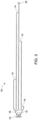
Figure 2 is a side view of the gas delivery device ofFigure 1 . -
Figure 3 is a bottom view of the gas delivery device ofFigure 1 . -
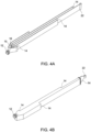
Figure 4A is an isometric view of the bottom of the gas delivery device ofFigure 1 . -
Figure 4B is an isometric view of the top of the gas delivery device ofFigure 1 . -
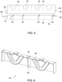
Figure 5 is a side view of the gas delivery device ofFigure 1 in combination with an intermittent gas sparger. -
Figure 6 is an isometric cross sectional view of the bottom of an alternative intermittent gas sparger. -
Figure 7 is a schematic cross section of a tank having a suction driven membrane module and an aeration system immersed in the tank. -
Figure 8 illustrates a method of aerating an immersed membrane module outside the scope of the claims. -
Figures 9-13 illustrate alternative methods of aerating an immerse module. - In a gas sparger as described in International Publication Number
2011/028341 , a unit of the sparger that receives a larger flow rate of input gas will produce pulses of bubbles at a higher frequency. In order to uniformly clean a membrane cassette, it may be desirable to have each unit operate at near the same frequency. The holes of the gas supply pipe are made small to help equalize the gas flow rate between holes feeding different units of the sparger. However, if the gas supply pipe is installed out of level by as few as 6 mm over a length of about 500 mm, the holes at higher elevation will have a noticeably larger gas flow rate. In addition, solids entering the gas supply pipe during maintenance periods when the gas supply is turned off can dry out or agglomerate when the gas is turned back. Occasionally, a solid particle is formed in the gas supply tube that is large or rigid enough to be lodged into one of the holes and to restrict or block the hole. A partially or completely blocked hole will in turn lead to poor distribution of gas to the membranes and allow solids to accumulate on the membranes. A gas delivery device will be described below that can be used as an alternative to such a gas supply pipe either with or without a further gas sparger. -
Figures 1 to 4 show different views of agas delivery device 10. Alternatively, thegas delivery device 10 may be called an aerator or a sparger. In use, thegas delivery device 10 is immersed in a liquid, typically water, for example activated sludge. Pressurized gas is supplied to aninlet 12 of the gas delivery device and is emitted as bubbles from a plurality ofoutlets 14. The gas is typically air, but in some applications another gas, for example biogas, nitrogen, ozone or oxygen may be used. Thegas delivery device 10 shown has fouroutlets 14, but there may alternatively be more orless outlets 14. - The
inlet 12 is separated from theoutlets 14 by a plurality ofports 16. Eachoutlet 14 communicates with aport 16 through achannel 18. Part of thegas delivery device 10 from theinlet 12 to theports 16 functions as amanifold 15, alternatively called a plenum, to distribute the gas entering through theinlet 12 among thechannels 18. Theinlet 12,ports 16 andoutlets 14 are located at generally the same elevation but spaced horizontally. The gas flows generally horizontally in thechannels 18. - The area of the
ports 16 is less than the area of thechannels 18, or less than the area of the smallest of thechannels 18 if they have different areas. For example, thechannels 14 may have a cross sectional area that is three times or more than the cross sectional area of theports 16. Theports 16 restrict the flow of gas into thechannels 14. The restriction provided by theports 16 helps to distribute the total airflow more nearly equally among thechannels 18. Decreasing the area of theports 16 produces a more nearly equal flow in thechannels 18 but also increases head loss through theports 16. Theports 16 may be made all of the same area. The area of theports 16 may be reduced until the flow is adequately distributed among thechannels 18. Optionally, aport 16 opening into a long ornarrow channel 18 may be larger than aport 16 opening into a short orwide channel 18 to help equalize the flow among thechannels 18. Alternatively, one ormore ports 16 may be made larger thanother ports 16 to intentionally increase the relative airflow through one ormore channels 18. This may be done, for example, to provide more air to the extremities of an immersed membrane cassette to counteract a tendency for water to be lifted preferentially through the center of a cassette. - As shown in
Figure 1 and Figure 2 , theports 16 are located close to each other in the horizontal direction. In this way, if thegas delivery device 10 is mounted a few degrees out of level, there is very little difference in elevation between theports 16. In particular, the largest horizontal distance between twoports 16 is less than the average horizontal distance betweenadjacent outlets 14, or less than half of the average horizontal distance betweenadjacent outlets 14. The largest horizontal distance between theports 16 is also less than 25%, or less than 10%, of the largest distance from aport 16 to anoutlet 14. This helps produce a more nearly equal distribution of the gas among thechannels 18 compared to an ordinary aerator in the form of a tube with holes when thegas delivery device 10 is mounted out of level. Because theports 16 are primarily responsible for equalizing flow betweenchannels 18, theoutlets 14 can be made larger, for example as large as the cross sectional area of thechannels 18, so that any solids that accumulate in achannel 18 are unlikely to block theoutlet 14. - The
gas delivery device 10 has itsoutlets 14 spaced generally in a line. Alternatively, other configurations may be used. For example,channels 18 could extend along a line but in both directions from theinlet 12. In another example, thechannels 18 could radiate from theinlet 12 like spokes from a wheel hub. - Optionally, the top of the
channels 18 may be pointed slightly upwards. In this way, if the gas delivery device is inadvertently mounted with a slightly downwards slant, then gas will not be trapped in thechannels 18 when the supply of gas is off. A slight upwards slant may also help compensate for differences between the lengths of thechannels 18. - Referring to
Figure 7 , thegas delivery device 10 may be used, for example, to provide bubbles for scouring an immersedmembrane module 50. Themembrane module 50 contains a plurality of ultrafiltration or microfiltration membranes. Permeate is withdrawn from the membrane module by way of a suction pump in communication with the inside of the membranes. A typical filtration cycle comprises periods of filtration interrupted by backwashing, alternatively called backpulsing, procedures or relaxation periods in which there is no filtration. A device with a line ofoutlets 14 is particular suited for providing bubbles to membrane modules with rectangular elements such as flat sheet modules or ZeeWeed™ hollow fiber elements sold by GE Water & Process Technologies. - The
gas delivery device 10 is immersed in atank 52 containing one ormore membrane modules 50. Thegas delivery device 10 may be mounted separately in thetank 52 or attached to themembrane modules 50. Gas may be brought down into the tank from ariser pipe 54 and then spread horizontally through asheader 56.Saddles 58 attached to theheader 56 receive gas from the header and carry the gas to a line of gas deliverdevices 10 oriented perpendicularly to theheader 56 in a generally horizontal plane. Optionally, agas delivery device 10 may be connected directly to aheader 56 orriser pipe 54. Streams ofbubbles 30 are discharged from theoutlets 14 at various lateral positions relative to amembrane module 50. The gas flowing to each lateral position bypasses any intermediate lateral positions. Thebubbles 30 may be allowed to rise directly to the membranes to clean them or inhibit fouling. Alternatively, a transducer may be placed above thegas delivery device 10 to modify its output before the bubbles reach the membranes. For example, a diffuser may be placed over an outlet to disperse the bubbles over a wider area. -
Figure 5 illustrates another transducer option in which anintermittent gas sparger 20, for example of the type shown in International Publication Number2011/028341 , is associated with the gas delivery device.Pressurized gas 28 is split in the gas delivery device into four bubble streams 30. Eachbubble stream 30 rises into adifferent cavity 32 of theintermittent air sparger 20. Gas flowing through aconduit 18 to aparticular cavity 32 bypasses any interveningcavities 32. - Each
cavity 32 has adischarge conduit 34, in the form a J-shaped tube in the example ofFigure 5 , which acts like an inverted siphon to discharge intermittent pulses of air from thecavity 32. Bubbles emitted from thegas delivery device 10 first collect in thecavity 32 forming a pocket of gas in the top of thecavity 32. No gas is emitted from thecavity 32 until the pocket of gas expands to reach the low point of thedischarge conduit 34. At that time, the pocket of gas empties out of thecavity 32 through theconduit 34 and the process repeats. In this way, a continuous stream ofbubbles 30 from thegas delivery device 10 is converted into an intermittent flow of bubbles from theintermittent gas sparger 20. - In
Figure 5 , thegas delivery device 10 is shown mounted separately and below theintermittent gas sparger 20. Alternatively, thegas delivery device 10 may be mounted to theintermittent gas sparger 20. In the example shown, theinlet 12 may be fitted into areceptacle 26 of theintermittent gas sparger 20. A fastener (not shown) is then placed through aneyelet 22 on thegas delivery device 10 and into anabutment 24 on theintermittent gas sparger 20. This results in thegas delivery device 10 being located partially within theintermittent gas sparger 20. However, theoutlets 14 are below theconduits 34 and still discharge into water below the lower limit of the pockets of gas in thecavities 32. -
Figure 6 is an isometric cross sectional view of the bottom of an alternativeintermittent sparger 40. In this example,multi-port conduits 42 provide two or more outlet paths extending upwards from the low point of eachmulti-port conduits 42. Adivider 44 between adjacentmulti-port conduits 42 has aslot 46 extending from the bottom of thedivider 44 to above the low point of themulti-port conduits 42. Each cavity with amulti-port conduit 42 replaces two cavities with a single outlet conduit and so avoids a need to balance the supply of gas between the two replaced cavities. Theslot 46 in thedivider 44 helps equalize the air supply to the cavities. Gas may flow in either direction through theslot 46 but the net flow will be from a cavity that receives a larger gas flow to a cavity that receives a lower air flow. - The
gas delivery device 10 is preferably an open-bottomed structure. For example, thechannels 18 are formed by side walls and a top. Thechannels 18 are open at the bottom and, preferably, at their ends. Theoutlets 14 are defined by the open end of thechannels 18. The manifold 15 between theinlet 12 and theports 16 is preferably also open at the bottom. Theports 16 are preferably slots also open at the bottom of thegas delivery device 10. In this way, solids caught anywhere in thegas delivery device 10 beyond theinlet 12 can fall or be expelled downwards out of thegas delivery device 10. Having such a short and simple pathway for solids to leave helps prevent fouling in thegas delivery device 10. In the event that solids somehow still accumulate in the gas delivery device, the open-bottomed structure makes it easy to locate and remove the solids, for example by spraying water into the bottom of thegas delivery device 10. - The open-bottomed construction of the
gas delivery device 10 also helps accommodate a range of input gas flow rates. At low flow rates, water enters into thegas delivery device 10 and reduces the size of theports 16 andchannels 18. At higher gas flow rates, less water enters into thegas delivery device 10 and theports 16 andchannels 18 increase in size. Thegas delivery device 10 can be made to provide a well distributed flow of air at supplied air flow rates that vary, for example, from a low flow rate to a high flow rate that is two or more times as large as the low flow rate. Thegas delivery device 10 may also be operated at one or more distinct intermediate flow rates or at flow rates that vary smoothly over time. This is done without thegas delivery device 10 fouling rapidly or providing excessive back pressure at either flow rate. In comparison, aerators in the form of a horizontal tube with a series of holes can foul and provide a poor distribution of air at low flow rates and excessive back pressure at high flow rates. -
Figure 8 shows a method of operating a membrane filtration system having amembrane module 50 immersed in atank 50 as shown inFigure 7 . The filtration system may be part of a membrane bioreactor (MBR). The operation consists of periods of permeation followed by periods of either relaxation or backpulse, alternatively call backwash. The periods of permeation may be from 10 to 50 times as long as the periods of backwashing or relaxation. The membranes are scoured with bubbles from agas delivery device 10, optionally in combination with anintermittent gas sparger 20. Scouring is used during both the permeation and the backpulse/relaxation cycles to control the accumulation of solids on the membranes and to reduce membrane fouling.Figure 8 illustrates of a method of air scouring in which the air flow rate remains the same throughout the permeation cycle and between permeation and relaxation cycles. During the permeation cycle, transmembrane pressure (TMP) slowly builds until the backpulse/relaxation cycle where at least some solids fouling the membrane are removed from themembrane module 50. When the next permeate cycle is begun, the TMP is reduced but begins to rise throughout the permeate cycle as more solids foul the membranes. -
Figures 9 to 13 show alternative methods of operating a membrane filtration system having amembrane module 50 immersed in atank 50 as shown inFigure 7 . When thegas delivery device 10 is used alone, the aeration flow rates inFigure 8 to 13 represent both the air flow input to thegas delivery device 10 and the output of thegas delivery device 10. When thegas delivery device 10 is used in combination with anintermittent gas sparger 20, the aeration flow rates inFigures 8 to 13 represent the air flow input to, and output from, thegas delivery device 10 and the time-averaged output of theintermittent gas sparger 20. However, the instantaneous flow rate of the output of theintermittent gas sparger 20 does not change much, or at all, with the input flow rate. Instead, the frequency at which bursts of bubbles are released from theintermittent gas sparger 20 increases with the input gas flow rate. Accordingly, in a system havingintermittent gas spargers 20, the aeration flow rates shown inFigures 8 to 13 may alternatively be thought of as representing the frequency of bursts of bubbles being released from theintermittent gas sparger 20. - In at least some situations, air scouring during backpulse/relaxation cycles is more effective in preventing solids accumulation and controlling membrane fouling compared to air scouring during permeation cycles. In one method, illustrated in
Figure 9 , the aeration flow rate remains constant at a first aeration flow rate during the permeation cycle. The aeration flow rate is increased during the backpulse/relaxation cycle to a second aeration flow rate which is greater than the first aeration flow rate. After the completion of the backpulse/relaxation cycle and at the beginning of a new permeation cycle, the aeration flow rate is decreased to the first aeration flow rate. In some cases, the amount of energy consumed by a membrane filtration system may be reduced by using the method ofFigure 9 rather than the method ofFigure 8 . - Solids build up in the module during the permeation cycle. The aeration flow rate can also be increased during the permeation cycle so that the aeration rate is higher during a later part of the cycle.
Figure 10 illustrates a method wherein the aeration flow rate at the beginning of the permeation cycle is gradually increased from a first aeration flow rate to a second aeration flow rate over the course of the permeation cycle and as solids build up. Alternatively, the aeration flow rate can go through one or more abrupt or step form changes from the first aeration flow rate to the second aeration flow rate within the permeation cycle. At the end of the permeation cycle and at the beginning of the backpulse/relaxation cycle, the aeration flow rate is increased to a third aeration flow rate. After the completion of the backpulse/relaxation cycle and at the beginning of a new permeation cycle, the aeration flow rate is decreased to the first aeration flow rate. -
Figure 11 illustrates a method wherein the aeration flow rate varies one or more times within a permeation cycle from a first aeration flow rate to a second aeration flow rate. During the backpulse/relaxation cycle, the second aeration flow rate or an even higher third aeration flow rate may be used. In the example illustrated, the aeration flow rate remains constant at a first aeration flow rate from the beginning of the permeation cycle. After a predetermined period of time during the course of the permeation cycle, the flow rate is increased from the first aeration flow rate to a second aeration flow rate for a predetermined period of time. After the completion of the predetermined period of time, the aeration flow rate is reduced to the first aeration flow rate. At the end of the permeation cycle and at the beginning of the backpulse/relaxation cycle, the aeration flow rate is increased to a third aeration flow rate, wherein the third aeration flow rate is greater than the second aeration flow rate. After the completion of the backpulse/relaxation cycle and at the beginning of a new permeation cycle, the aeration flow rate is decreased to the first aeration flow rate. - While
Figure 11 illustrates two occurrences of an increase of the aeration flow rate from the first flow rate to the second flow rate, any number of occurrences of an increase of the aeration flow rate may be applied during the permeation cycle. The first aeration flow rate illustrated inFigure 11 may be any flow rate. For example, the first aeration flow rate of the air scouring method illustrated inFigure 11 may be zero. -
Figure 12 illustrates a method wherein aeration is provided in distinct periods of time during the permeation cycle. The aeration flow rate increases from one distinct period of time to the next and then the aeration flow rate may be further increased during the backpulse/relaxation cycle. Optionally, a lower aeration flow rate, or no air flow, may be provided between the distinct periods of time. In the example shown, the aeration flow rate remains constant at a first aeration flow rate from the beginning of the permeation cycle. After a predetermined period of time during the course of the permeation cycle, the flow rate is increased from the first aeration flow rate to a second aeration flow rate for a predetermined period of time. After the completion of the predetermined period of time, the aeration flow rate is reduced to the first aeration flow rate. After another predetermined period of time, the flow rate is increased from the first aeration flow rate to a third aeration flow rate for a predetermined period of time, wherein the third aeration flow rate is greater than the second aeration flow rate. At the end of the permeation cycle and at the beginning of the backpulse/relaxation cycle, the aeration flow rate is increased to a fourth aeration flow rate, wherein the fourth aeration flow rate is greater than the third aeration flow rate. After the completion of the backpulse/relaxation cycle and at the beginning of a new permeation cycle, the aeration flow rate is decreased to the first aeration flow rate. - While
Figure 12 illustrates two occurrences of an increase of the aeration flow rate during the permeation cycle, any number of occurrences of an increase of the aeration flow rate may be applied during the permeation cycle. The first aeration flow rate illustrated inFigure 12 may be any flow rate. According to one embodiment, the first aeration flow rate of the air scouring method illustrated inFigure 12 may be zero. -
Figure 13 illustrates a method wherein air scouring is only used during the backpulse/relaxation cycle and all aeration is discontinued during the permeation cycle. As illustrated, an aeration flow rate of zero is applied during the permeation cycle. At the end of the permeation cycle and at the beginning of the backpulse/relaxation cycle, the aeration flow rate is increased to a first aeration flow rate. After the completion of the backpulse/relaxation cycle and at the beginning of a new permeation cycle, the aeration flow rate is decreased to zero. - In the description above, one or more aeration flow rates are said to begin with the beginning of a backwash/relaxation cycle and to end with the completion of a backwash/relaxation cycle. This is meant to be approximate. The stated aeration flow rate preferably includes at least the period of time occupied by the backwash or relaxation but may begin before the backwash or relaxation, or continue after the backwash or relaxation, or both.
-
Figures 8 to 13 do not have specific time scales. However, permeation cycles typically last for 15 minutes or more, sometime 30 minutes or more. Backwash/relaxation cycles are typically at least one minute long and sometimes more than two minutes long. Changes in aeration flow rate between discrete aeration flow rates during the permeation period are preferably applied for at least one minute, more preferably for at least two minutes or five minutes. In contrast, anintermittent gas sparger 20 typically releases bursts of bubbles once every 4 to 30 seconds, more often once every 4 to 15 seconds. Accordingly, the changes in aeration flow rate shown inFigures 8 to 13 do not represent individual bursts of bubbles from anintermittent gas sparger 20. Instead, if anintermittent gas sparger 20 is used, it typically releases a plurality of bursts of bubbles within a period of time shown as having a particular aeration flow rate. - The aeration flow rate (or frequency of bursts of bubbles from an intermittent gas sparger 20) could also be controlled considering one or more properties of feed water, of water in a process tank of a bioreactor or the
tank 52 containing amembrane module 50, or considering the performance of themembrane module 50. Viscosity, mixed liquor suspended solids (MLSS) concentrations, extracellular polymer (ECP) concentrations, soluble microbial product (SMP) concentrations, a fouling index, temperature, and a rate of membrane fouling or recovery of flux after backwashing are some of the properties that could be used to control aeration flow rate, to determine when to change between one or more of the methods shown inFigures 8 to 13 , or to control the timing of changes between aeration flow rates in a method shown inFigures 9 to 13 . For example, a higher aeration flow rate, or more time at a higher aeration flow rate, or a change to a more intensive aeration process may be applied as the viscosity of water being fed to the filtration system of thetank 52 increases or its temperature decreases. In another example, a higher aeration flow rate, or more time at a higher aeration flow rate, or a change to a more intensive aeration process may be applied at higher MLSS concentrations. In another example, a higher aeration flow rate, or more time at a higher aeration flow rate, or a change to a more intensive aeration process may be applied when electricity may be obtained at a lower cost. - Optionally, to reduce the frequency of changes in the speed of a blower proving gas to a plurality of gas delivery devices 10 (alone or in combination with intermittent gas spargers 20), a valve set may be provided between a blower and the
gas delivery devices 10. The valve set distributes the flow provided by the blower between two or more distinct branches of an air delivery system connected to the gas delivery devices such that flow in one distinct branch may vary in a time period during which the blower output does nto vary. For example, at one period of time a higher aeration flow rate is applied to a first distinct branch and a lower aeration flow rate is applied to a second distinct branch, while at a second period of time the higher aeration flow rate is applied to the second distinct branch and the lower aeration flow rate is applied to the first distinct branch. Alternatively or additionally, the blower may provide air at a generally constant rate to a pressure tank or other accumulator while a valve between the pressure tank and thegas delivery device 10 is modulated to provide the required variation in aeration flow rate. - Optionally,
gas delivery devices 10 may also be connected to a cyclic aeration system as used in some ZeeWeed MBRs sold by GE Water and Process Technologies. In this case, even without anintermittent gas sparger 20, thegas delivery device 10 produces a flow of bubbles for a period of about 2 to 20 seconds followed by a period in which thegas delivery device 10 produces a lesser flow of bubbles or no bubbles for a period of about 2 to 60 seconds, these periods alternating in repeated cycles over time. For example, onegas delivery device 10 can produce bubbles for 10 seconds and then be off for 10 seconds while a second gas delivery device is off for 10 seconds and then produces bubbles for 10 seconds. In this case, in the methods ofFigures 8 to 13 , the aeration flow rate can be interpreted as a time averaged aeration flow rate. - This written description uses examples to disclose the invention, including the best mode, and also to enable any person skilled in the art to practice the invention, including making and using any devices or systems and performing any incorporated methods.
Claims (8)
- A method of air scouring an immersed membrane module comprising adjusting one or more aeration parameters; between successive permeation cycles, successive back pulse cycles or successive relaxation cycles; during a permeation cycle; between a permeation cycle and a backpulse cycle; or, between a permeation cycle and a relaxation cycle; further comprising steps of,a) bringing a flow of pressurized gas into a tank to below the bottom of a membrane module;b) supplying the pressurized gas to an inlet 12 and splitting the flow of pressurized gas with a plurality of ports 16 into multiple flows of pressurized gas below the membrane module;c) directing each of the multiple flows of pressurized gas through channels 18 to a different lateral position having an outlet 14, the outlet 14 being defined by an open end of the channel 18;d) releasing bubbles only from the outlet 14 of the different lateral positions,the inlet 12, port 16 and outlets 14 being located at generally the same elevation but spaced horizontally and the pressurized gas flows generally horizontally in the channels.
- The method of claim 1 wherein an aeration flow rate is varied between successive permeation cycles.
- The method of any of claims 1 to 2 wherein an aeration flow rate is increased during a backpulse or relaxation cycle relative to the aeration flow rate during a preceding permeation cycle.
- The method of any of claims 1 to 3 wherein an aeration flow rate is increased within a permeation cycle.
- The method of any of claims 1 to 4 wherein aeration is provided intermittently during a permeation cycle.
- The method of claim 1 wherein aeration is provided only during a backpulse or a relaxation cycle.
- The method of claim 1 wherein a continuous or instantaneous aeration flow rate increases generally linearly over time during a permeation cycle.
- The method of claim 7 wherein the aeration flow rate increases further during a backpulse or relaxation cycle.
Applications Claiming Priority (2)
| Application Number | Priority Date | Filing Date | Title |
|---|---|---|---|
| US201261726092P | 2012-11-14 | 2012-11-14 | |
| PCT/US2013/032213 WO2014077888A1 (en) | 2012-11-14 | 2013-03-15 | Method for scouring immersed membranes using a open bottom multiple channel delivery device |
Publications (2)
| Publication Number | Publication Date |
|---|---|
| EP2919892A1 EP2919892A1 (en) | 2015-09-23 |
| EP2919892B1 true EP2919892B1 (en) | 2024-09-18 |
Family
ID=48142924
Family Applications (1)
| Application Number | Title | Priority Date | Filing Date |
|---|---|---|---|
| EP13717600.4A Active EP2919892B1 (en) | 2012-11-14 | 2013-03-15 | Method for scouring immersed membranes using multiple channel delivery device |
Country Status (13)
| Country | Link |
|---|---|
| US (2) | US10765976B2 (en) |
| EP (1) | EP2919892B1 (en) |
| KR (1) | KR102069929B1 (en) |
| CN (1) | CN104768632B (en) |
| AU (1) | AU2013345397B2 (en) |
| BR (1) | BR112015009721A2 (en) |
| CA (1) | CA2891409A1 (en) |
| ES (1) | ES2997632T3 (en) |
| HU (1) | HUE069558T2 (en) |
| PL (1) | PL2919892T3 (en) |
| PT (1) | PT2919892T (en) |
| RU (1) | RU2620056C2 (en) |
| WO (1) | WO2014077888A1 (en) |
Families Citing this family (6)
| Publication number | Priority date | Publication date | Assignee | Title |
|---|---|---|---|---|
| US10828607B2 (en) | 2012-08-09 | 2020-11-10 | Lotte Chemical Corporation | Aerator device, filter system including an aerator device, and method of aerating a filter using an aerator device |
| KR102706720B1 (en) | 2013-02-22 | 2024-09-12 | 비엘 테크놀러지스 인크. | Membrane assembly for supporting a biofilm |
| KR101704864B1 (en) * | 2013-12-31 | 2017-02-08 | 롯데케미칼 주식회사 | Aerator device and filter system including the same |
| US10160679B2 (en) * | 2014-03-20 | 2018-12-25 | Bl Technologies, Inc. | Wastewater treatment with primary treatment and MBR or MABR-IFAS reactor |
| CN110015751B (en) * | 2019-03-07 | 2022-04-29 | 博天环境集团股份有限公司 | Membrane component energy-saving aeration method of MBR system |
| CN114394663B (en) * | 2022-03-01 | 2024-04-19 | 浙江长兴求是膜技术有限公司 | Air distribution device |
Citations (3)
| Publication number | Priority date | Publication date | Assignee | Title |
|---|---|---|---|---|
| US20110049047A1 (en) * | 2009-09-03 | 2011-03-03 | Jeff Cumin | Gas sparger for an immersed membrane |
| US20120091602A1 (en) * | 2010-10-15 | 2012-04-19 | Jeffrey Ronald Cumin | Integrated gas sparger for an immersed membrane |
| US20130069256A1 (en) * | 2011-09-15 | 2013-03-21 | Zenon Technology Partnership | Method and apparatus to keep an aerator full of air |
Family Cites Families (9)
| Publication number | Priority date | Publication date | Assignee | Title |
|---|---|---|---|---|
| US3424443A (en) * | 1967-04-11 | 1969-01-28 | Water Pollution Control Corp | Apparatus for diffusing gas into a liquid |
| US7087173B2 (en) * | 1995-08-11 | 2006-08-08 | Zenon Environmental Inc. | Inverted cavity aerator for membrane module |
| DE69916479T2 (en) * | 1998-10-09 | 2005-03-24 | Zenon Environmental Inc., Oakville | CYCLIC WORKING VENTILATION SYSTEM FOR DIVE MEMBRANE MODULE |
| US6547968B1 (en) * | 1999-07-30 | 2003-04-15 | Zenon Environmental Inc. | Pulsed backwash for immersed membranes |
| WO2005082498A1 (en) * | 2004-02-27 | 2005-09-09 | Zenon Environmental Inc. | Water filtration using immersed membranes |
| US8377305B2 (en) * | 2004-09-15 | 2013-02-19 | Siemens Industry, Inc. | Continuously variable aeration |
| JP4906269B2 (en) * | 2005-04-27 | 2012-03-28 | 前澤工業株式会社 | Filtration device |
| US20070095754A1 (en) * | 2005-10-28 | 2007-05-03 | Dennis Livingston | Efficient MBR operation in wastewater treatment |
| US20120103892A1 (en) | 2010-10-28 | 2012-05-03 | General Electric Company | Separation module |
-
2013
- 2013-03-15 WO PCT/US2013/032213 patent/WO2014077888A1/en not_active Ceased
- 2013-03-15 KR KR1020157015217A patent/KR102069929B1/en active Active
- 2013-03-15 RU RU2015116948A patent/RU2620056C2/en active
- 2013-03-15 CN CN201380059578.8A patent/CN104768632B/en active Active
- 2013-03-15 BR BR112015009721A patent/BR112015009721A2/en not_active Application Discontinuation
- 2013-03-15 EP EP13717600.4A patent/EP2919892B1/en active Active
- 2013-03-15 ES ES13717600T patent/ES2997632T3/en active Active
- 2013-03-15 US US14/442,807 patent/US10765976B2/en active Active
- 2013-03-15 HU HUE13717600A patent/HUE069558T2/en unknown
- 2013-03-15 AU AU2013345397A patent/AU2013345397B2/en active Active
- 2013-03-15 CA CA2891409A patent/CA2891409A1/en active Pending
- 2013-03-15 PT PT137176004T patent/PT2919892T/en unknown
- 2013-03-15 PL PL13717600.4T patent/PL2919892T3/en unknown
-
2020
- 2020-02-27 US US16/803,837 patent/US20200197840A1/en active Pending
Patent Citations (3)
| Publication number | Priority date | Publication date | Assignee | Title |
|---|---|---|---|---|
| US20110049047A1 (en) * | 2009-09-03 | 2011-03-03 | Jeff Cumin | Gas sparger for an immersed membrane |
| US20120091602A1 (en) * | 2010-10-15 | 2012-04-19 | Jeffrey Ronald Cumin | Integrated gas sparger for an immersed membrane |
| US20130069256A1 (en) * | 2011-09-15 | 2013-03-21 | Zenon Technology Partnership | Method and apparatus to keep an aerator full of air |
Also Published As
| Publication number | Publication date |
|---|---|
| PT2919892T (en) | 2024-12-02 |
| HUE069558T2 (en) | 2025-03-28 |
| AU2013345397A1 (en) | 2015-05-21 |
| EP2919892A1 (en) | 2015-09-23 |
| AU2013345397B2 (en) | 2018-01-04 |
| US20200197840A1 (en) | 2020-06-25 |
| CA2891409A1 (en) | 2014-05-22 |
| CN104768632B (en) | 2016-11-09 |
| WO2014077888A1 (en) | 2014-05-22 |
| CN104768632A (en) | 2015-07-08 |
| US10765976B2 (en) | 2020-09-08 |
| KR20150084040A (en) | 2015-07-21 |
| BR112015009721A2 (en) | 2017-07-04 |
| KR102069929B1 (en) | 2020-01-23 |
| RU2015116948A (en) | 2017-01-10 |
| ES2997632T3 (en) | 2025-02-17 |
| US20150290563A1 (en) | 2015-10-15 |
| PL2919892T3 (en) | 2025-02-03 |
| RU2620056C2 (en) | 2017-05-22 |
Similar Documents
| Publication | Publication Date | Title |
|---|---|---|
| US20200197840A1 (en) | Open bottom multiple channel gas delivery device for immersed membranes | |
| US10173175B2 (en) | Integrated gas sparger for an immersed membrane | |
| JP6200931B2 (en) | Gas sparger for filtration membrane | |
| EP2882525B1 (en) | Aerator device, filter system, and method of aerating a filter | |
| CN106040002A (en) | Membrane cleaning with pulsed airlift pump | |
| EP2919891B1 (en) | Open bottom multiple channel gas delivery device for immersed membranes | |
| US9463419B2 (en) | Pulse aeration for immersed membranes | |
| US20130015130A1 (en) | Pulse aeration for immersed membranes |
Legal Events
| Date | Code | Title | Description |
|---|---|---|---|
| PUAI | Public reference made under article 153(3) epc to a published international application that has entered the european phase |
Free format text: ORIGINAL CODE: 0009012 |
|
| 17P | Request for examination filed |
Effective date: 20150615 |
|
| AK | Designated contracting states |
Kind code of ref document: A1 Designated state(s): AL AT BE BG CH CY CZ DE DK EE ES FI FR GB GR HR HU IE IS IT LI LT LU LV MC MK MT NL NO PL PT RO RS SE SI SK SM TR |
|
| AX | Request for extension of the european patent |
Extension state: BA ME |
|
| DAX | Request for extension of the european patent (deleted) | ||
| RAP1 | Party data changed (applicant data changed or rights of an application transferred) |
Owner name: BL TECHNOLOGIES, INC. |
|
| STAA | Information on the status of an ep patent application or granted ep patent |
Free format text: STATUS: EXAMINATION IS IN PROGRESS |
|
| 17Q | First examination report despatched |
Effective date: 20190328 |
|
| P01 | Opt-out of the competence of the unified patent court (upc) registered |
Effective date: 20230521 |
|
| GRAP | Despatch of communication of intention to grant a patent |
Free format text: ORIGINAL CODE: EPIDOSNIGR1 |
|
| STAA | Information on the status of an ep patent application or granted ep patent |
Free format text: STATUS: GRANT OF PATENT IS INTENDED |
|
| INTG | Intention to grant announced |
Effective date: 20240415 |
|
| GRAS | Grant fee paid |
Free format text: ORIGINAL CODE: EPIDOSNIGR3 |
|
| GRAA | (expected) grant |
Free format text: ORIGINAL CODE: 0009210 |
|
| STAA | Information on the status of an ep patent application or granted ep patent |
Free format text: STATUS: THE PATENT HAS BEEN GRANTED |
|
| AK | Designated contracting states |
Kind code of ref document: B1 Designated state(s): AL AT BE BG CH CY CZ DE DK EE ES FI FR GB GR HR HU IE IS IT LI LT LU LV MC MK MT NL NO PL PT RO RS SE SI SK SM TR |
|
| REG | Reference to a national code |
Ref country code: GB Ref legal event code: FG4D |
|
| REG | Reference to a national code |
Ref country code: CH Ref legal event code: EP |
|
| REG | Reference to a national code |
Ref country code: DE Ref legal event code: R096 Ref document number: 602013086099 Country of ref document: DE |
|
| REG | Reference to a national code |
Ref country code: IE Ref legal event code: FG4D |
|
| REG | Reference to a national code |
Ref country code: SE Ref legal event code: TRGR |
|
| REG | Reference to a national code |
Ref country code: NL Ref legal event code: FP |
|
| REG | Reference to a national code |
Ref country code: PT Ref legal event code: SC4A Ref document number: 2919892 Country of ref document: PT Date of ref document: 20241202 Kind code of ref document: T Free format text: AVAILABILITY OF NATIONAL TRANSLATION Effective date: 20241126 |
|
| REG | Reference to a national code |
Ref country code: LT Ref legal event code: MG9D |
|
| PG25 | Lapsed in a contracting state [announced via postgrant information from national office to epo] |
Ref country code: NO Free format text: LAPSE BECAUSE OF FAILURE TO SUBMIT A TRANSLATION OF THE DESCRIPTION OR TO PAY THE FEE WITHIN THE PRESCRIBED TIME-LIMIT Effective date: 20241218 |
|
| PG25 | Lapsed in a contracting state [announced via postgrant information from national office to epo] |
Ref country code: GR Free format text: LAPSE BECAUSE OF FAILURE TO SUBMIT A TRANSLATION OF THE DESCRIPTION OR TO PAY THE FEE WITHIN THE PRESCRIBED TIME-LIMIT Effective date: 20241219 Ref country code: FI Free format text: LAPSE BECAUSE OF FAILURE TO SUBMIT A TRANSLATION OF THE DESCRIPTION OR TO PAY THE FEE WITHIN THE PRESCRIBED TIME-LIMIT Effective date: 20240918 |
|
| PG25 | Lapsed in a contracting state [announced via postgrant information from national office to epo] |
Ref country code: BG Free format text: LAPSE BECAUSE OF FAILURE TO SUBMIT A TRANSLATION OF THE DESCRIPTION OR TO PAY THE FEE WITHIN THE PRESCRIBED TIME-LIMIT Effective date: 20240918 |
|
| PG25 | Lapsed in a contracting state [announced via postgrant information from national office to epo] |
Ref country code: LV Free format text: LAPSE BECAUSE OF FAILURE TO SUBMIT A TRANSLATION OF THE DESCRIPTION OR TO PAY THE FEE WITHIN THE PRESCRIBED TIME-LIMIT Effective date: 20240918 |
|
| PG25 | Lapsed in a contracting state [announced via postgrant information from national office to epo] |
Ref country code: HR Free format text: LAPSE BECAUSE OF FAILURE TO SUBMIT A TRANSLATION OF THE DESCRIPTION OR TO PAY THE FEE WITHIN THE PRESCRIBED TIME-LIMIT Effective date: 20240918 |
|
| PG25 | Lapsed in a contracting state [announced via postgrant information from national office to epo] |
Ref country code: RS Free format text: LAPSE BECAUSE OF FAILURE TO SUBMIT A TRANSLATION OF THE DESCRIPTION OR TO PAY THE FEE WITHIN THE PRESCRIBED TIME-LIMIT Effective date: 20241218 |
|
| PG25 | Lapsed in a contracting state [announced via postgrant information from national office to epo] |
Ref country code: RS Free format text: LAPSE BECAUSE OF FAILURE TO SUBMIT A TRANSLATION OF THE DESCRIPTION OR TO PAY THE FEE WITHIN THE PRESCRIBED TIME-LIMIT Effective date: 20241218 Ref country code: NO Free format text: LAPSE BECAUSE OF FAILURE TO SUBMIT A TRANSLATION OF THE DESCRIPTION OR TO PAY THE FEE WITHIN THE PRESCRIBED TIME-LIMIT Effective date: 20241218 Ref country code: LV Free format text: LAPSE BECAUSE OF FAILURE TO SUBMIT A TRANSLATION OF THE DESCRIPTION OR TO PAY THE FEE WITHIN THE PRESCRIBED TIME-LIMIT Effective date: 20240918 Ref country code: HR Free format text: LAPSE BECAUSE OF FAILURE TO SUBMIT A TRANSLATION OF THE DESCRIPTION OR TO PAY THE FEE WITHIN THE PRESCRIBED TIME-LIMIT Effective date: 20240918 Ref country code: GR Free format text: LAPSE BECAUSE OF FAILURE TO SUBMIT A TRANSLATION OF THE DESCRIPTION OR TO PAY THE FEE WITHIN THE PRESCRIBED TIME-LIMIT Effective date: 20241219 Ref country code: FI Free format text: LAPSE BECAUSE OF FAILURE TO SUBMIT A TRANSLATION OF THE DESCRIPTION OR TO PAY THE FEE WITHIN THE PRESCRIBED TIME-LIMIT Effective date: 20240918 Ref country code: BG Free format text: LAPSE BECAUSE OF FAILURE TO SUBMIT A TRANSLATION OF THE DESCRIPTION OR TO PAY THE FEE WITHIN THE PRESCRIBED TIME-LIMIT Effective date: 20240918 |
|
| REG | Reference to a national code |
Ref country code: AT Ref legal event code: MK05 Ref document number: 1724210 Country of ref document: AT Kind code of ref document: T Effective date: 20240918 |
|
| REG | Reference to a national code |
Ref country code: ES Ref legal event code: FG2A Ref document number: 2997632 Country of ref document: ES Kind code of ref document: T3 Effective date: 20250217 |
|
| REG | Reference to a national code |
Ref country code: HU Ref legal event code: AG4A Ref document number: E069558 Country of ref document: HU |
|
| PG25 | Lapsed in a contracting state [announced via postgrant information from national office to epo] |
Ref country code: IS Free format text: LAPSE BECAUSE OF FAILURE TO SUBMIT A TRANSLATION OF THE DESCRIPTION OR TO PAY THE FEE WITHIN THE PRESCRIBED TIME-LIMIT Effective date: 20250118 |
|
| PG25 | Lapsed in a contracting state [announced via postgrant information from national office to epo] |
Ref country code: RO Free format text: LAPSE BECAUSE OF FAILURE TO SUBMIT A TRANSLATION OF THE DESCRIPTION OR TO PAY THE FEE WITHIN THE PRESCRIBED TIME-LIMIT Effective date: 20240918 Ref country code: SM Free format text: LAPSE BECAUSE OF FAILURE TO SUBMIT A TRANSLATION OF THE DESCRIPTION OR TO PAY THE FEE WITHIN THE PRESCRIBED TIME-LIMIT Effective date: 20240918 |
|
| PG25 | Lapsed in a contracting state [announced via postgrant information from national office to epo] |
Ref country code: AT Free format text: LAPSE BECAUSE OF FAILURE TO SUBMIT A TRANSLATION OF THE DESCRIPTION OR TO PAY THE FEE WITHIN THE PRESCRIBED TIME-LIMIT Effective date: 20240918 Ref country code: EE Free format text: LAPSE BECAUSE OF FAILURE TO SUBMIT A TRANSLATION OF THE DESCRIPTION OR TO PAY THE FEE WITHIN THE PRESCRIBED TIME-LIMIT Effective date: 20240918 |
|
| PG25 | Lapsed in a contracting state [announced via postgrant information from national office to epo] |
Ref country code: CZ Free format text: LAPSE BECAUSE OF FAILURE TO SUBMIT A TRANSLATION OF THE DESCRIPTION OR TO PAY THE FEE WITHIN THE PRESCRIBED TIME-LIMIT Effective date: 20240918 |
|
| PG25 | Lapsed in a contracting state [announced via postgrant information from national office to epo] |
Ref country code: SK Free format text: LAPSE BECAUSE OF FAILURE TO SUBMIT A TRANSLATION OF THE DESCRIPTION OR TO PAY THE FEE WITHIN THE PRESCRIBED TIME-LIMIT Effective date: 20240918 |
|
| REG | Reference to a national code |
Ref country code: DE Ref legal event code: R097 Ref document number: 602013086099 Country of ref document: DE |
|
| PG25 | Lapsed in a contracting state [announced via postgrant information from national office to epo] |
Ref country code: DK Free format text: LAPSE BECAUSE OF FAILURE TO SUBMIT A TRANSLATION OF THE DESCRIPTION OR TO PAY THE FEE WITHIN THE PRESCRIBED TIME-LIMIT Effective date: 20240918 |
|
| PLBE | No opposition filed within time limit |
Free format text: ORIGINAL CODE: 0009261 |
|
| STAA | Information on the status of an ep patent application or granted ep patent |
Free format text: STATUS: NO OPPOSITION FILED WITHIN TIME LIMIT |
|
| 26N | No opposition filed |
Effective date: 20250619 |
|
| PG25 | Lapsed in a contracting state [announced via postgrant information from national office to epo] |
Ref country code: MC Free format text: LAPSE BECAUSE OF FAILURE TO SUBMIT A TRANSLATION OF THE DESCRIPTION OR TO PAY THE FEE WITHIN THE PRESCRIBED TIME-LIMIT Effective date: 20240918 |
|
| REG | Reference to a national code |
Ref country code: CH Ref legal event code: H13 Free format text: ST27 STATUS EVENT CODE: U-0-0-H10-H13 (AS PROVIDED BY THE NATIONAL OFFICE) Effective date: 20251023 |
|
| PG25 | Lapsed in a contracting state [announced via postgrant information from national office to epo] |
Ref country code: LU Free format text: LAPSE BECAUSE OF NON-PAYMENT OF DUE FEES Effective date: 20250315 |
|
| PG25 | Lapsed in a contracting state [announced via postgrant information from national office to epo] |
Ref country code: CH Free format text: LAPSE BECAUSE OF NON-PAYMENT OF DUE FEES Effective date: 20250331 |
|
| PG25 | Lapsed in a contracting state [announced via postgrant information from national office to epo] |
Ref country code: IE Free format text: LAPSE BECAUSE OF NON-PAYMENT OF DUE FEES Effective date: 20250315 |
|
| PGFP | Annual fee paid to national office [announced via postgrant information from national office to epo] |
Ref country code: SE Payment date: 20260327 Year of fee payment: 14 |
|
| PGFP | Annual fee paid to national office [announced via postgrant information from national office to epo] |
Ref country code: GB Payment date: 20260327 Year of fee payment: 14 |
|
| PGFP | Annual fee paid to national office [announced via postgrant information from national office to epo] |
Ref country code: DE Payment date: 20260327 Year of fee payment: 14 |
|
| PGFP | Annual fee paid to national office [announced via postgrant information from national office to epo] |
Ref country code: BE Payment date: 20260327 Year of fee payment: 14 Ref country code: IT Payment date: 20260319 Year of fee payment: 14 |
|
| PGFP | Annual fee paid to national office [announced via postgrant information from national office to epo] |
Ref country code: HU Payment date: 20260225 Year of fee payment: 14 Ref country code: NL Payment date: 20260326 Year of fee payment: 14 |
|
| PGFP | Annual fee paid to national office [announced via postgrant information from national office to epo] |
Ref country code: FR Payment date: 20260325 Year of fee payment: 14 |
|
| PGFP | Annual fee paid to national office [announced via postgrant information from national office to epo] |
Ref country code: TR Payment date: 20260220 Year of fee payment: 14 |
|
| PGFP | Annual fee paid to national office [announced via postgrant information from national office to epo] |
Ref country code: PT Payment date: 20260224 Year of fee payment: 14 |
|
| PGFP | Annual fee paid to national office [announced via postgrant information from national office to epo] |
Ref country code: PL Payment date: 20260219 Year of fee payment: 14 |
|
| PG25 | Lapsed in a contracting state [announced via postgrant information from national office to epo] |
Ref country code: CY Free format text: LAPSE BECAUSE OF FAILURE TO SUBMIT A TRANSLATION OF THE DESCRIPTION OR TO PAY THE FEE WITHIN THE PRESCRIBED TIME-LIMIT Effective date: 20240918 |
|
| PG25 | Lapsed in a contracting state [announced via postgrant information from national office to epo] |
Ref country code: LT Free format text: LAPSE BECAUSE OF FAILURE TO SUBMIT A TRANSLATION OF THE DESCRIPTION OR TO PAY THE FEE WITHIN THE PRESCRIBED TIME-LIMIT Effective date: 20240918 |
|
| PGFP | Annual fee paid to national office [announced via postgrant information from national office to epo] |
Ref country code: ES Payment date: 20260401 Year of fee payment: 14 |