EP2919480A1 - Cable management arm assembly - Google Patents
Cable management arm assembly Download PDFInfo
- Publication number
- EP2919480A1 EP2919480A1 EP14158474.8A EP14158474A EP2919480A1 EP 2919480 A1 EP2919480 A1 EP 2919480A1 EP 14158474 A EP14158474 A EP 14158474A EP 2919480 A1 EP2919480 A1 EP 2919480A1
- Authority
- EP
- European Patent Office
- Prior art keywords
- supporting member
- arm
- base
- supporting
- connecting unit
- Prior art date
- Legal status (The legal status is an assumption and is not a legal conclusion. Google has not performed a legal analysis and makes no representation as to the accuracy of the status listed.)
- Granted
Links
Images





Classifications
-
- H—ELECTRICITY
- H04—ELECTRIC COMMUNICATION TECHNIQUE
- H04Q—SELECTING
- H04Q1/00—Details of selecting apparatus or arrangements
- H04Q1/02—Constructional details
- H04Q1/06—Cable ducts or mountings specially adapted for exchange installations
-
- H—ELECTRICITY
- H05—ELECTRIC TECHNIQUES NOT OTHERWISE PROVIDED FOR
- H05K—PRINTED CIRCUITS; CASINGS OR CONSTRUCTIONAL DETAILS OF ELECTRIC APPARATUS; MANUFACTURE OF ASSEMBLAGES OF ELECTRICAL COMPONENTS
- H05K7/00—Constructional details common to different types of electric apparatus
- H05K7/14—Mounting supporting structure in casing or on frame or rack
- H05K7/1485—Servers; Data center rooms, e.g. 19-inch computer racks
- H05K7/1488—Cabinets therefor, e.g. chassis or racks or mechanical interfaces between blades and support structures
- H05K7/1491—Cabinets therefor, e.g. chassis or racks or mechanical interfaces between blades and support structures having cable management arrangements
Definitions
- the present invention relates to a cable management arm assembly and more particularly to a supporting structure for cable management.
- the present invention relates to a cable management arm assembly. More particularly, the present invention relates to a structurally simple design for holding, managing, and securely supporting cables.
- a cable management arm assembly includes: a first arm; a second arm; a cable base pivotally connected between the first arm and the second arm; a plate fixedly connected to the bottom of the cable base; a supporting base; a first connecting unit connected to the first arm; a second connecting unit connected to the second arm; a third connecting unit connected to the supporting base; a first supporting member pivotally connected to the supporting base and abutting against the supporting base; a second supporting member movably connected to the first supporting member and extensible/retractable relative to the first supporting member; and a sliding base connected to the plate and movably connected to the second supporting member.
- the first arm is mounted at a fixed first predetermined position via the first connecting unit.
- the second arm is mounted at a variable second predetermined position via the second connecting unit.
- the supporting base is mounted at a fixed third predetermined position via the third connecting unit.
- the cable management arm assembly further includes an elastic element connected between the first supporting member and the second supporting member so that the second supporting member can be elastically pulled relative to the first supporting member by the elastic element.
- the second supporting member has a first stop block and a second stop block, both corresponding in position to the sliding base so that the sliding base can slide between the first stop block and the second stop block.
- the sliding base drives the second supporting member to displace relative to the first supporting member.
- the first supporting member has a first hook
- the second supporting member has a second hook
- the elastic element is connected to the first hook and the second hook.
- the supporting base has a first supporting portion and a second supporting portion substantially perpendicular to the first supporting portion.
- the third connecting unit is pivotally connected to the first supporting portion, and the first supporting member is pivotally connected to the second supporting portion.
- the first supporting portion of the supporting base has a first projection and a second projection
- the third connecting unit has a first positioning hole and a second positioning hole.
- the plate has a curved sliding groove, and the sliding base is connected to the curved sliding groove via a first connecting element so as to rotate relative to the plate in a limited manner.
- the cable management arm assembly further includes: a first slide rail assembly at least including a first fixed rail and a first movable rail longitudinally and slidably displaceable relative to the first fixed rail; and a second slide rail assembly at least including a second fixed rail and a second movable rail longitudinally and slidably displaceable relative to the second fixed rail.
- the first connecting unit is mounted on the first fixed rail of the first slide rail assembly and is thereby fixed at the first predetermined position.
- the second connecting unit is mounted on the first movable rail of the first slide rail assembly and is thus located at the second predetermined position, wherein the second predetermined position is variable in response to sliding of the first movable rail relative to the first fixed rail.
- the third connecting unit is mounted on the second fixed rail of the second slide rail assembly and is thereby fixed at the third predetermined position.
- a cable management system of the present invention includes a first slide rail assembly, a second slide rail assembly, a first arm, a second arm, a cable base, a supporting base, a first supporting member, a second supporting member, an elastic element, and a sliding base.
- the first slide rail assembly at least includes a first fixed rail and a first movable rail.
- the first movable rail can be longitudinally and slidably displaced relative to the first fixed rail.
- the second slide rail assembly at least includes a second fixed rail and a second movable rail.
- the second movable rail can be longitudinally and slidably displaced relative to the second fixed rail.
- the first arm is connected to the first fixed rail of the first slide rail assembly.
- the second arm is connected to the first movable rail of the first slide rail assembly.
- the cable base is pivotally connected between the first arm and the second arm.
- the supporting base is connected to the second fixed rail of the second slide rail assembly.
- the first supporting member is pivotally connected to the supporting base and abuts against the supporting base.
- the second supporting member is slidably connected to the first supporting member.
- the elastic element is connected between the first supporting member and the second supporting member.
- the sliding base is pivotally connected to the cable base and is slidably connected to the second supporting member.
- the second arm When the first slide rail assembly and the second slide rail assembly are extended, the second arm is displaced away from the first arm, the sliding base moves away from the supporting base by sliding on the second supporting member, and the sliding base drives the second supporting member to extend from the first supporting member and drives the first supporting member to rotate relative to the supporting base.
- the first slide rail assembly and the second slide rail assembly are retracted, the second arm is brought close to the first arm, and the second supporting member is displaced relative to the first supporting member in response to the elastic force generated by the elastic element.
- the cable management arm assembly in one embodiment of the present invention includes a first arm 10, a second arm 12, a cable base 14, a supporting base 16, a first connecting unit 18, a second connecting unit 20, a third connecting unit 22, a first supporting member 24, a second supporting member 26, an elastic element 28, a sliding base 30, and a plurality of cable holders 32.
- the cable holders 32 are configured for holding cables (not shown) and are provided on the first arm 10, the second arm 12, and the cable base 14.
- the cable base 14 is pivotally connected between the first arm 10 and the second arm 12.
- the cable base 14 includes a plate 34.
- the plate 34 is a separate component fixedly connected to the bottom of the cable base 14.
- the plate 34 is integrally formed with the cable base 14. Therefore, the plate 34 can be viewed as a portion of the cable base 14.
- the plate 34 has a curved sliding groove 36.
- the supporting base 16 has a first supporting portion 38 and a second supporting portion 40 substantially perpendicular to the first supporting portion 38.
- the first connecting unit 18 is connected to the first arm 10 and includes a first engaging base 42 and a first connecting base 44 pivotally connected to the first engaging base 42.
- the first connecting base 44 is pivotally connected to the first arm 10.
- the second connecting unit 20 is connected to the second arm 12 and includes a second engaging base 43 and a second connecting base 46 pivotally connected to the second engaging base 43.
- the second connecting base 46 is pivotally connected to the second arm 12.
- the third connecting unit 22 is pivotally connected to the first supporting portion 38 of the supporting base 16 via a first pivoting element 48.
- the first supporting member 24 is pivotally connected to the second supporting portion 40 of the supporting base 16 via a second pivoting element 50. In addition, the first supporting member 24 abuts against the second supporting portion 40 of the supporting base 16.
- the second supporting member 26 is movably connected to the first supporting member 24. More specifically, the second supporting member 26 has a channel 52, and the first supporting member 24 is disposed in the channel 52 such that the second supporting member 26 is displaceable relative to the first supporting member 24.
- the first supporting member 24 has a first hook 54, which preferably extends integrally from the first supporting member 24, and the second supporting member 26 has a second hook 56, which preferably extends integrally from the second supporting member 26.
- the second supporting member 26 is provided with a first stop block 58 and a second stop block 60 at two ends respectively.
- the elastic element 28 is connected to the first hook 54 of the first supporting member 24 and the second hook 56 of the second supporting member 26, so that the second supporting member 26 can be elastically pulled relative to the first supporting member 24 by the elastic element 28.
- the second supporting member 26 can be displaced relative to the first supporting member 24 in response to the elastic force generated by the elastic element 28.
- the second supporting member 26 can be pulled relative to the first supporting member 24 from an extended state to a retracted state by the elastic force generated by the elastic element 28.
- the sliding base 30 has a first end portion 31a and a second end portion 31b.
- a first connecting element 33a passes through the curved sliding groove 36 of the plate 34 and is connected adjacent to the first end portion 31a of the sliding base 30 so that the sliding base 30 can rotate relative to the plate 34 in a limited space defined by the curved sliding groove 36.
- the second end portion 31b of the sliding base 30 is pivotally connected to the plate 34 via a second connecting element 33b.
- the sliding base 30 is movably located between the first stop block 58 and the second stop block 60 of the second supporting member 26. It should be noted that, as stated above, the plate 34 can be viewed as a portion of the cable base 14, and so can the sliding base 30 connected to the cable base 14.
- the cable management arm assembly of the present invention is mounted on a first slide rail assembly 62 and a second slide rail assembly 64, which are provided in pairs.
- the first slide rail assembly 62 at least includes a first fixed rail 66 and a first movable rail 68, wherein the first movable rail 68 is longitudinally and slidably displaceable relative to the first fixed rail 66.
- the second slide rail assembly 64 at least includes a second fixed rail 70 and a second movable rail 72, wherein the second movable rail 72 is longitudinally and slidably displaceable relative to the second fixed rail 70.
- a server apparatus 74 can be mounted on the first movable rail 68 of the first slide rail assembly 62 and the second movable rail 72 of the second slide rail assembly 64 and have its cables (not shown) arranged by means of the first arm 10, the second arm 12, and the cable base 14.
- the first arm 10 is connected to the first fixed rail 66 of the first slide rail assembly 62 via the first engaging base 42 of the first connecting unit 18 such that one end of the first arm 10 is fixed at a first predetermined position.
- the second arm 12 is connected to the first movable rail 68 of the first slide rail assembly 62 via the second engaging base 43 of the second connecting unit 20 such that one end of the second arm 12 is located at a second predetermined position.
- the second predetermined position is variable because the first movable rail 68 of the first slide rail assembly 62 can slide relative to the first fixed rail 66.
- the supporting base 16 is connected to the second fixed rail 70 of the second slide rail assembly 64 via the third connecting unit 22 and is thereby fixed at a third predetermined position.
- the first slide rail assembly 62 and the second slide rail assembly 64 are in the retracted state, as shown in FIG. 3 , the second arm 12 and the first arm 10 are brought close to each other, forming a suspended member spanning a large distance. In this state, the center of gravity of the entire cable management arm assembly is located at P1. More specifically, the second supporting member 26 is retracted relative to the first supporting member 24, and the first supporting member 24 abuts against the supporting base 16. Therefore, when the first arm 10 and the second arm 12 are in a closed state in which they are close to each other, it is mainly the supporting base 16 that supports the cable management arm assembly; the load on the first connecting unit 18 and the second connecting unit 20 is relatively small.
- the sliding base 30 is pivotally connected to the cable base 14 via the second connecting element 33b, the sliding base 30 itself has rotated relative to the cable base 14 and the plate 34 in a limited space defined by the curved sliding groove 36, thanks to the first connecting element 33a.
- the center of gravity of the entire cable management arm assembly is located at P2, with the supporting base 16 and the second supporting member 26 (together with the first supporting member 24) jointly providing effective support.
- the second connecting unit 20 of the second arm 12 has been further displaced relative to the first connecting unit 18 of the first arm 10 such that the second connecting unit 20 is spaced from the first connecting unit 18 by a second distance L2.
- the cable base 14 and the plate 34 have slid along the second supporting member 26 to the first stop block 58, and after being stopped at the first stop block 58, the sliding base 30 has driven the second supporting member 26 to extend from the first supporting member 24 and has driven the first supporting member 24 to rotate relative to the supporting base 16.
- the elastic element 28 is stretched by the second supporting member 26 and generates an elastic force for pulling back the second supporting member 26.
- the center of gravity of the entire cable management arm assembly in this state is situated at P3.
- the second connecting unit 20 of the second arm 12 is spaced from the first connecting unit 18 of the first arm 10 by a third distance L3 after being further displaced relative to the first connecting unit 18.
- the cable base 14 and the plate 34 have, by means of the sliding base 30, driven the second supporting member 26 to extend further from the first supporting member 24 while the elastic element 28 continues applying an elastic force to the second supporting member 26.
- the center of gravity of the entire cable management arm assembly is located at P4, which is close to the center of the cable management arm assembly; therefore, the weight of the cable management arm assembly is jointly supported by the supporting base 16, the first connecting unit 18, and the second connecting unit 20.
- the second connecting unit 20 of the second arm 12 has been further displaced relative to the first connecting unit 18 of the first arm 10 to a fully extended position, where the second connecting unit 20 is spaced from the first connecting unit 18 by a fourth distance L4.
- the cable base 14 and the plate 34 have, by means of the sliding base 30, driven the second supporting member 26 to extend fully from the first supporting member 24, with the second supporting member 26 still subjected to the elastic force of the elastic element 28.
- the gravity center of the entire cable management arm assembly is located at P5, which is close to the first slide rail assembly 62. Consequently, most of the weight of the cable management arm assembly is jointly borne by the first connecting unit 18 and the second connecting unit 20.
- the second supporting member 26 is automatically pulled back relative to the first supporting member 24 due to the elastic force generated by the elastic element 28.
- the sliding base 30 will be displaced along the second supporting member 26 toward the supporting base 16, stop at the second stop block 60, and stay there until the second supporting member 26 is fully retracted relative to the first supporting member 24, i.e., when the cable management arm assembly is fully closed.
- the sliding base 30 may be directly fixed to the plate 34 of the cable base 14, provided that the length of the first arm 10 is extensible, allowing the sliding base 30 to slide along the second supporting member 26.
- the supporting base 16 is connected to the second movable rail 72 of the second slide rail assembly 64 via the third connecting unit 22.
- the working principle of the cable management arm assembly in this configuration is similar to when the third connecting unit 22 is connected to the second fixed rail 70 and therefore will not be stated repeatedly.
- the first supporting portion 38 of the supporting base 16 has a first projection 76 and a second projection 78
- the third connecting unit 22 has a first positioning hole 80 and a second positioning hole 82.
- the cable management arm assembly of the present invention not only can provide stable static support when in the closed state, but also can redistribute its own weight between its components when extended to different degrees and thereby provide dynamic support. Hence, the cable management arm assembly will not sag excessively when loaded with cables.
Landscapes
- Engineering & Computer Science (AREA)
- Computer Networks & Wireless Communication (AREA)
- Computer Hardware Design (AREA)
- General Engineering & Computer Science (AREA)
- Microelectronics & Electronic Packaging (AREA)
- Electric Cable Arrangement Between Relatively Moving Parts (AREA)
Abstract
Description
- The present invention relates to a cable management arm assembly and more particularly to a supporting structure for cable management.
- The supporting structure of cable management arms has been disclosed in
US Patent No. 7,472,795 B2, granted to Dubon et al. ;US Patent No. 7,654,398 B2, granted to Bridges et al. ;US Patent No. 7,746,667 B1, granted to Baiza et al. ; andUS Patent Nos. 7,554,819 B2 ;7,712,615 B2 ;8,231,014 B2 ; and8,251,321 B2, granted to Chen et al . - However, the foregoing supporting structures for cable management arms leave room for improvement especially in terms of the convenience of installation and use. In view of this, the inventor of the present invention envisioned designing a more simple supporting structure.
- The present invention relates to a cable management arm assembly. More particularly, the present invention relates to a structurally simple design for holding, managing, and securely supporting cables.
- According to one aspect of the present invention, a cable management arm assembly includes: a first arm; a second arm; a cable base pivotally connected between the first arm and the second arm; a plate fixedly connected to the bottom of the cable base; a supporting base; a first connecting unit connected to the first arm; a second connecting unit connected to the second arm; a third connecting unit connected to the supporting base; a first supporting member pivotally connected to the supporting base and abutting against the supporting base; a second supporting member movably connected to the first supporting member and extensible/retractable relative to the first supporting member; and a sliding base connected to the plate and movably connected to the second supporting member. The first arm is mounted at a fixed first predetermined position via the first connecting unit. The second arm is mounted at a variable second predetermined position via the second connecting unit. The supporting base is mounted at a fixed third predetermined position via the third connecting unit. When the second connecting unit of the second arm is displaced away from the first connecting unit of the first arm, the cable base is moved away from the supporting base due to the sliding base sliding on the second supporting member, and the sliding base drives the second supporting member to extend relative to the first supporting member and drives the first supporting member to rotate relative to the supporting base.
- Preferably, the cable management arm assembly further includes an elastic element connected between the first supporting member and the second supporting member so that the second supporting member can be elastically pulled relative to the first supporting member by the elastic element.
- Preferably, the second supporting member has a first stop block and a second stop block, both corresponding in position to the sliding base so that the sliding base can slide between the first stop block and the second stop block. Once stopped at the first stop block, the sliding base drives the second supporting member to displace relative to the first supporting member.
- Preferably, the first supporting member has a first hook, the second supporting member has a second hook, and the elastic element is connected to the first hook and the second hook.
- Preferably, the supporting base has a first supporting portion and a second supporting portion substantially perpendicular to the first supporting portion. The third connecting unit is pivotally connected to the first supporting portion, and the first supporting member is pivotally connected to the second supporting portion.
- Preferably, the first supporting portion of the supporting base has a first projection and a second projection, and the third connecting unit has a first positioning hole and a second positioning hole. When the third connecting unit is rotated in a first direction relative to the supporting base to a first position, the first projection of the third connecting unit is engaged in the first positioning hole such that the third connecting unit is fixed in position. When the third connecting unit is rotated in a second direction relative to the supporting base to a second position, the second projection of the third connecting unit is engaged in the second positioning hole such that the third connecting unit is fixed in position.
- Preferably, the plate has a curved sliding groove, and the sliding base is connected to the curved sliding groove via a first connecting element so as to rotate relative to the plate in a limited manner.
- Preferably, the cable management arm assembly further includes: a first slide rail assembly at least including a first fixed rail and a first movable rail longitudinally and slidably displaceable relative to the first fixed rail; and a second slide rail assembly at least including a second fixed rail and a second movable rail longitudinally and slidably displaceable relative to the second fixed rail. The first connecting unit is mounted on the first fixed rail of the first slide rail assembly and is thereby fixed at the first predetermined position. The second connecting unit is mounted on the first movable rail of the first slide rail assembly and is thus located at the second predetermined position, wherein the second predetermined position is variable in response to sliding of the first movable rail relative to the first fixed rail. The third connecting unit is mounted on the second fixed rail of the second slide rail assembly and is thereby fixed at the third predetermined position.
- According to another aspect of the present invention, a cable management system of the present invention includes a first slide rail assembly, a second slide rail assembly, a first arm, a second arm, a cable base, a supporting base, a first supporting member, a second supporting member, an elastic element, and a sliding base. The first slide rail assembly at least includes a first fixed rail and a first movable rail. The first movable rail can be longitudinally and slidably displaced relative to the first fixed rail. The second slide rail assembly at least includes a second fixed rail and a second movable rail. The second movable rail can be longitudinally and slidably displaced relative to the second fixed rail. The first arm is connected to the first fixed rail of the first slide rail assembly. The second arm is connected to the first movable rail of the first slide rail assembly. The cable base is pivotally connected between the first arm and the second arm. The supporting base is connected to the second fixed rail of the second slide rail assembly. The first supporting member is pivotally connected to the supporting base and abuts against the supporting base. The second supporting member is slidably connected to the first supporting member. The elastic element is connected between the first supporting member and the second supporting member. The sliding base is pivotally connected to the cable base and is slidably connected to the second supporting member. When the first slide rail assembly and the second slide rail assembly are extended, the second arm is displaced away from the first arm, the sliding base moves away from the supporting base by sliding on the second supporting member, and the sliding base drives the second supporting member to extend from the first supporting member and drives the first supporting member to rotate relative to the supporting base. When the first slide rail assembly and the second slide rail assembly are retracted, the second arm is brought close to the first arm, and the second supporting member is displaced relative to the first supporting member in response to the elastic force generated by the elastic element.
- The invention as well as a preferred mode of use and the advantages thereof will be best understood by referring to the following detailed description of some illustrative embodiments in conjunction with the accompanying drawings, wherein:
-
FIG. 1 is an exploded perspective view of an embodiment of the present invention; -
FIG. 2 is a partial view of the embodiment depicted inFIG. 1 ; -
FIG. 3 is a schematic drawing in which the cable management arm assembly in the embodiment depicted inFIG. 1 is in a closed position; -
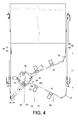
FIG. 4 is a schematic drawing in which the second connecting unit of the second arm in the embodiment depicted inFIG. 1 is spaced apart from the first connecting unit of the first arm by a first distance; -
FIG. 5 is a schematic drawing in which the second connecting unit of the second arm in the embodiment depicted inFIG. 1 is spaced apart from the first connecting unit of the first arm by a second distance; -
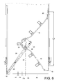
FIG. 6 is a schematic drawing in which the second connecting unit of the second arm in the embodiment depicted inFIG. 1 is spaced apart from the first connecting unit of the first arm by a third distance; -
FIG. 7 is a schematic drawing in which the second connecting unit of the second arm in the embodiment depicted inFIG. 1 is spaced apart from the first connecting unit of the first arm by a fourth distance; -
FIG. 8 is a schematic drawing in which the third connecting unit in the embodiment depicted inFIG. 1 is connected to the second movable rail of the second slide rail assembly; and -
FIG. 9 shows that the third connecting unit in the embodiment depicted inFIG. 1 can be switched between different positions relative to the supporting base. - As shown in
FIG. 1 andFIG. 2 , the cable management arm assembly in one embodiment of the present invention includes afirst arm 10, asecond arm 12, acable base 14, a supportingbase 16, a first connectingunit 18, a second connectingunit 20, a third connectingunit 22, a first supportingmember 24, a second supportingmember 26, anelastic element 28, asliding base 30, and a plurality ofcable holders 32. Thecable holders 32 are configured for holding cables (not shown) and are provided on thefirst arm 10, thesecond arm 12, and thecable base 14. - The
cable base 14 is pivotally connected between thefirst arm 10 and thesecond arm 12. Thecable base 14 includes aplate 34. In one preferred embodiment, theplate 34 is a separate component fixedly connected to the bottom of thecable base 14. Alternatively, theplate 34 is integrally formed with thecable base 14. Therefore, theplate 34 can be viewed as a portion of thecable base 14. In one preferred embodiment, theplate 34 has a curved slidinggroove 36. - The supporting
base 16 has a first supportingportion 38 and a second supportingportion 40 substantially perpendicular to the first supportingportion 38. - The first connecting
unit 18 is connected to thefirst arm 10 and includes a first engagingbase 42 and a first connectingbase 44 pivotally connected to the first engagingbase 42. In one preferred embodiment, the first connectingbase 44 is pivotally connected to thefirst arm 10. - The second connecting
unit 20 is connected to thesecond arm 12 and includes a second engagingbase 43 and a second connectingbase 46 pivotally connected to the second engagingbase 43. In one preferred embodiment, the second connectingbase 46 is pivotally connected to thesecond arm 12. - The third connecting
unit 22 is pivotally connected to the first supportingportion 38 of the supportingbase 16 via afirst pivoting element 48. - The first supporting
member 24 is pivotally connected to the second supportingportion 40 of the supportingbase 16 via asecond pivoting element 50. In addition, the first supportingmember 24 abuts against the second supportingportion 40 of the supportingbase 16. - The second supporting
member 26 is movably connected to the first supportingmember 24. More specifically, the second supportingmember 26 has achannel 52, and the first supportingmember 24 is disposed in thechannel 52 such that the second supportingmember 26 is displaceable relative to the first supportingmember 24. In one preferred embodiment, the first supportingmember 24 has afirst hook 54, which preferably extends integrally from the first supportingmember 24, and the second supportingmember 26 has asecond hook 56, which preferably extends integrally from the second supportingmember 26. Moreover, the second supportingmember 26 is provided with afirst stop block 58 and asecond stop block 60 at two ends respectively. - The
elastic element 28 is connected to thefirst hook 54 of the first supportingmember 24 and thesecond hook 56 of the second supportingmember 26, so that the second supportingmember 26 can be elastically pulled relative to the first supportingmember 24 by theelastic element 28. In other words, the second supportingmember 26 can be displaced relative to the first supportingmember 24 in response to the elastic force generated by theelastic element 28. For example, the second supportingmember 26 can be pulled relative to the first supportingmember 24 from an extended state to a retracted state by the elastic force generated by theelastic element 28. - The sliding
base 30 has afirst end portion 31a and asecond end portion 31b. A first connectingelement 33a passes through the curved slidinggroove 36 of theplate 34 and is connected adjacent to thefirst end portion 31a of the slidingbase 30 so that the slidingbase 30 can rotate relative to theplate 34 in a limited space defined by the curved slidinggroove 36. Preferably, thesecond end portion 31b of the slidingbase 30 is pivotally connected to theplate 34 via a second connectingelement 33b. Further, the slidingbase 30 is movably located between thefirst stop block 58 and thesecond stop block 60 of the second supportingmember 26. It should be noted that, as stated above, theplate 34 can be viewed as a portion of thecable base 14, and so can the slidingbase 30 connected to thecable base 14. - In
FIG. 3 , the cable management arm assembly of the present invention is mounted on a firstslide rail assembly 62 and a secondslide rail assembly 64, which are provided in pairs. The firstslide rail assembly 62 at least includes a first fixedrail 66 and a firstmovable rail 68, wherein the firstmovable rail 68 is longitudinally and slidably displaceable relative to the first fixedrail 66. Similarly, the secondslide rail assembly 64 at least includes a second fixedrail 70 and a secondmovable rail 72, wherein the secondmovable rail 72 is longitudinally and slidably displaceable relative to the second fixedrail 70. Aserver apparatus 74 can be mounted on the firstmovable rail 68 of the firstslide rail assembly 62 and the secondmovable rail 72 of the secondslide rail assembly 64 and have its cables (not shown) arranged by means of thefirst arm 10, thesecond arm 12, and thecable base 14. Thefirst arm 10 is connected to the first fixedrail 66 of the firstslide rail assembly 62 via the first engagingbase 42 of the first connectingunit 18 such that one end of thefirst arm 10 is fixed at a first predetermined position. Thesecond arm 12 is connected to the firstmovable rail 68 of the firstslide rail assembly 62 via the second engagingbase 43 of the second connectingunit 20 such that one end of thesecond arm 12 is located at a second predetermined position. The second predetermined position is variable because the firstmovable rail 68 of the firstslide rail assembly 62 can slide relative to the first fixedrail 66. The supportingbase 16 is connected to the second fixedrail 70 of the secondslide rail assembly 64 via the third connectingunit 22 and is thereby fixed at a third predetermined position. When the firstslide rail assembly 62 and the secondslide rail assembly 64 are in the retracted state, as shown inFIG. 3 , thesecond arm 12 and thefirst arm 10 are brought close to each other, forming a suspended member spanning a large distance. In this state, the center of gravity of the entire cable management arm assembly is located at P1. More specifically, the second supportingmember 26 is retracted relative to the first supportingmember 24, and the first supportingmember 24 abuts against the supportingbase 16. Therefore, when thefirst arm 10 and thesecond arm 12 are in a closed state in which they are close to each other, it is mainly the supportingbase 16 that supports the cable management arm assembly; the load on the first connectingunit 18 and the second connectingunit 20 is relatively small. - In
FIG 4 , the firstmovable rail 68 of the firstslide rail assembly 62 and the secondmovable rail 72 of the secondslide rail assembly 64 have been pulled out preliminarily. As a result, the second connectingunit 20 of thesecond arm 12 is displaced relative to the first connectingunit 18 of thefirst arm 10 by a first distance L1. Limited by theelastic element 28, the second supportingmember 26 in this state has yet to extend from the first supportingmember 24. Thecable base 14 and theplate 34, on the other hand, have slid linearly along the second supportingmember 26 via the slidingbase 30, and thecable base 14 has displaced in response to the displacement of thesecond arm 12. Through the slidingbase 30 and the second supportingmember 26, thecable base 14 has driven the first supportingmember 24 to rotate relative to the supportingbase 16. Meanwhile, due to the fact that the slidingbase 30 is pivotally connected to thecable base 14 via the second connectingelement 33b, the slidingbase 30 itself has rotated relative to thecable base 14 and theplate 34 in a limited space defined by the curved slidinggroove 36, thanks to the first connectingelement 33a. In this state, the center of gravity of the entire cable management arm assembly is located at P2, with the supportingbase 16 and the second supporting member 26 (together with the first supporting member 24) jointly providing effective support. - In
FIG 5 , the second connectingunit 20 of thesecond arm 12 has been further displaced relative to the first connectingunit 18 of thefirst arm 10 such that the second connectingunit 20 is spaced from the first connectingunit 18 by a second distance L2. With the help of the slidingbase 30, thecable base 14 and theplate 34 have slid along the second supportingmember 26 to thefirst stop block 58, and after being stopped at thefirst stop block 58, the slidingbase 30 has driven the second supportingmember 26 to extend from the first supportingmember 24 and has driven the first supportingmember 24 to rotate relative to the supportingbase 16. Meanwhile, theelastic element 28 is stretched by the second supportingmember 26 and generates an elastic force for pulling back the second supportingmember 26. The center of gravity of the entire cable management arm assembly in this state is situated at P3. - In
FIG. 6 , the second connectingunit 20 of thesecond arm 12 is spaced from the first connectingunit 18 of thefirst arm 10 by a third distance L3 after being further displaced relative to the first connectingunit 18. Thecable base 14 and theplate 34 have, by means of the slidingbase 30, driven the second supportingmember 26 to extend further from the first supportingmember 24 while theelastic element 28 continues applying an elastic force to the second supportingmember 26. In this state, the center of gravity of the entire cable management arm assembly is located at P4, which is close to the center of the cable management arm assembly; therefore, the weight of the cable management arm assembly is jointly supported by the supportingbase 16, the first connectingunit 18, and the second connectingunit 20. - In
FIG 7 , the second connectingunit 20 of thesecond arm 12 has been further displaced relative to the first connectingunit 18 of thefirst arm 10 to a fully extended position, where the second connectingunit 20 is spaced from the first connectingunit 18 by a fourth distance L4. Thecable base 14 and theplate 34 have, by means of the slidingbase 30, driven the second supportingmember 26 to extend fully from the first supportingmember 24, with the second supportingmember 26 still subjected to the elastic force of theelastic element 28. In this state, the gravity center of the entire cable management arm assembly is located at P5, which is close to the firstslide rail assembly 62. Consequently, most of the weight of the cable management arm assembly is jointly borne by the first connectingunit 18 and the second connectingunit 20. - It should be pointed out that, while the cable management arm assembly returns to the closed state, the second supporting
member 26 is automatically pulled back relative to the first supportingmember 24 due to the elastic force generated by theelastic element 28. The slidingbase 30 will be displaced along the second supportingmember 26 toward the supportingbase 16, stop at thesecond stop block 60, and stay there until the second supportingmember 26 is fully retracted relative to the first supportingmember 24, i.e., when the cable management arm assembly is fully closed. - Apart from being pivotally connected to the
plate 34 in a rotatable configuration, the slidingbase 30 may be directly fixed to theplate 34 of thecable base 14, provided that the length of thefirst arm 10 is extensible, allowing the slidingbase 30 to slide along the second supportingmember 26. - In one preferred embodiment as shown in
FIG 8 , the supportingbase 16 is connected to the secondmovable rail 72 of the secondslide rail assembly 64 via the third connectingunit 22. The working principle of the cable management arm assembly in this configuration is similar to when the third connectingunit 22 is connected to the second fixedrail 70 and therefore will not be stated repeatedly. - Referring to
FIG. 9 , the first supportingportion 38 of the supportingbase 16 has afirst projection 76 and asecond projection 78, and the third connectingunit 22 has afirst positioning hole 80 and asecond positioning hole 82. When the third connectingunit 22 is rotated in a first direction F1 relative to the supportingbase 16 to a first position, thefirst projection 76 of the third connectingunit 22 is engaged in thefirst positioning hole 80 to fix the third connectingunit 22 in position. When the third connectingunit 22 is rotated in a second direction F2 relative to the supportingbase 16 to a second position, thesecond projection 78 of the third connectingunit 22 is engaged in thesecond positioning hole 82 to fix the third connectingunit 22 in position. This technical feature allows the cable management arm assembly to be used when laterally reversed. - As stated above, the cable management arm assembly of the present invention not only can provide stable static support when in the closed state, but also can redistribute its own weight between its components when extended to different degrees and thereby provide dynamic support. Hence, the cable management arm assembly will not sag excessively when loaded with cables.
- It is understood that the preferred embodiments provided herein are intended only to demonstrate the present invention by way of example and should not be construed as restrictive of the scope of the present invention. The scope of the present invention is defined only by the appended claims.
Claims (10)
- A cable management arm assembly comprising:a first arm (10);a second arm (12);a cable base (14) pivotally connected between the first arm (10) and the second arm (12);a plate (34) fixedly connected to a bottom of the cable base (14); anda supporting base (16); characterized in that said cable management arm assembly further comprises:a first supporting member (24) pivotally connected to the supporting base (16) and abutting against the supporting base (16);a second supporting member (26) movably connected to the first supporting member (24); anda sliding base (30) connected to the plate (34) and movably connected to the second supporting member (26);wherein when the second arm (12) is displaced away from the first arm (10), the sliding base (30) moves away from the supporting base (16) by sliding on the second supporting member (26), and the sliding base (30) drives the second supporting member (26) to extend relative to the first supporting member (24) and drives the first supporting member (24) to rotate relative to the supporting base (16).
- The cable management arm assembly of claim 1, further comprising:a first connecting unit (18) connected to the first arm (10);a second connecting unit (20) connected to the second arm (12); anda third connecting unit (22) connected to the supporting base (16);wherein the second supporting member (26) is extensible and retractable relative to the first supporting member (24); the first arm (10) is mounted at a fixed first predetermined position via the first connecting unit (18); the second arm (12) is mounted at a variable second predetermined position via the second connecting unit (20); and the supporting base (16) is mounted at a fixed third predetermined position via the third connecting unit (22); andwherein when the second arm (12) is displaced away from the first arm (10), the second connecting unit (20) of the second arm (12) is displaced away from the first connecting unit (18) of the first arm (10), and the cable base (14) is moved away from the supporting base (16) due to the sliding base (30) sliding on the second supporting member (26).
- The cable management arm assembly of claim 2, further comprising an elastic element (28) connected between the first supporting member (24) and the second supporting member (26) so that the second supporting member (26) can be elastically pulled relative to the first supporting member (24) by the elastic element (28).
- The cable management arm assembly of claim 2, wherein the second supporting member (26) has a first stop block (58) and a second stop block (60), both said stop blocks (58, 60) corresponding in position to the sliding base (30) so that the sliding base (30) is slidable between the first stop block (58) and the second stop block (60); and the sliding base (30), once stopped at the first stop block (58), drives the second supporting member (26) to displace relative to the first supporting member (24).
- The cable management arm assembly of claim 3, wherein the first supporting member (24) has a first hook (54), the second supporting member (26) has a second hook (56), and the elastic element (28) is connected to the first hook (54) and the second hook (56).
- The cable management arm assembly of claim 2, wherein the supporting base (16) has a first supporting portion (38) and a second supporting portion (40) substantially perpendicular to the first supporting portion (38), the third connecting unit (22) being pivotally connected to the first supporting portion (38), the first supporting member (24) being pivotally connected to the second supporting portion (40).
- The cable management arm assembly of claim 6, wherein the first supporting portion (38) of the supporting base (16) has a first projection (76) and a second projection (78); the third connecting unit (22) has a first positioning hole (80) and a second positioning hole (82); when the third connecting unit (22) is rotated in a first direction (F1) relative to the supporting base (16) to a first position, the first projection (76) of the third connecting unit (22) is engaged in the first positioning hole (80) to fix the third connecting unit (22) in position; and when the third connecting unit (22) is rotated in a second direction (F2) relative to the supporting base (16) to a second position, the second projection (78) of the third connecting unit (22) is engaged in the second positioning hole (82) to fix the third connecting unit (22) in position.
- The cable management arm assembly of claim 2, wherein the plate (34) has a curved sliding groove (36), and the sliding base (30) is connected to the curved sliding groove (36) via a first connecting element (33a) so as to rotate relative to the plate (34) in a limited manner.
- The cable management arm assembly of claim 2, further comprising:a first slide rail assembly (62) comprising a first fixed rail (66) and a first movable rail (68) longitudinally and slidably displaceable relative to the first fixed rail (66); anda second slide rail assembly (64) comprising a second fixed rail (70) and a second movable rail (72) longitudinally and slidably displaceable relative to the second fixed rail (70);wherein the first connecting unit (18) is mounted on the first fixed rail (66) of the first slide rail assembly (62) to be fixed at the first predetermined position; the second connecting unit (20) is mounted on the first movable rail (68) of the first slide rail assembly (62) to be located at the second predetermined position, the second predetermined position being variable in response to sliding of the first movable rail (68) relative to the first fixed rail (66); and the third connecting unit (22) is mounted on the second fixed rail (70) of the second slide rail assembly (64) and to be fixed at the third predetermined position.
- A cable management system comprising the cable management arm assembly according to claim 1 and further comprising:a first slide rail assembly (62) comprising a first fixed rail (66) and a first movable rail (68), the first movable rail (68) being longitudinally slidable relative to the first fixed rail (66); anda second slide rail assembly (64) comprising a second fixed rail (70) and a second movable rail (72), the second movable rail (72) being longitudinally slidable relative to the second fixed rail (70); characterized in that the cable management system further comprises an elastic element (28) connected between the first supporting member (24) and the second supporting member (26);wherein the first arm (10) is connected to the first fixed rail (66) of the first slide rail assembly (62); the second arm (12) is connected to the first movable rail (68) of the first slide rail assembly (62); and the supporting base (16) is connected to the second fixed rail (70) of the second slide rail assembly (64);wherein when the first slide rail assembly (62) and the second slide rail assembly (64) are extended, the second arm (12) is displaced away from the first arm (10), the sliding base (30) moves away from the supporting base (16) by sliding on the second supporting member (26), and the sliding base (30) drives the second supporting member (26) to extend relative to the first supporting member (24) and drives the first supporting member (24) to rotate relative to the supporting base (16); andwherein when the first slide rail assembly (62) and the second slide rail assembly (64) are retracted, the second arm (12) is brought close to the first arm (10), and the second supporting member (26) is displaced relative to the first supporting member (24) in response to an elastic force generated by the elastic element (28).
Priority Applications (1)
| Application Number | Priority Date | Filing Date | Title |
|---|---|---|---|
| EP14158474.8A EP2919480B1 (en) | 2014-03-10 | 2014-03-10 | Cable management arm assembly |
Applications Claiming Priority (1)
| Application Number | Priority Date | Filing Date | Title |
|---|---|---|---|
| EP14158474.8A EP2919480B1 (en) | 2014-03-10 | 2014-03-10 | Cable management arm assembly |
Publications (2)
| Publication Number | Publication Date |
|---|---|
| EP2919480A1 true EP2919480A1 (en) | 2015-09-16 |
| EP2919480B1 EP2919480B1 (en) | 2016-09-21 |
Family
ID=50238236
Family Applications (1)
| Application Number | Title | Priority Date | Filing Date |
|---|---|---|---|
| EP14158474.8A Active EP2919480B1 (en) | 2014-03-10 | 2014-03-10 | Cable management arm assembly |
Country Status (1)
| Country | Link |
|---|---|
| EP (1) | EP2919480B1 (en) |
Cited By (2)
| Publication number | Priority date | Publication date | Assignee | Title |
|---|---|---|---|---|
| CN111629557A (en) * | 2019-02-27 | 2020-09-04 | 川湖科技股份有限公司 | Slide rail mechanism and its support assembly |
| CN112449541A (en) * | 2019-09-05 | 2021-03-05 | 川湖科技股份有限公司 | Connection assembly and wire arranging device thereof |
Citations (7)
| Publication number | Priority date | Publication date | Assignee | Title |
|---|---|---|---|---|
| US7472795B2 (en) | 2003-12-05 | 2009-01-06 | Pentair Electronic Packaging Company | Anti-sag management assembly |
| US20090078834A1 (en) * | 2004-10-15 | 2009-03-26 | King Slide Works Co., Ltd. | Support slide assembly for cable management arm |
| US7554819B2 (en) | 2004-10-15 | 2009-06-30 | King Slide Works Co., Ltd. | Cable management arm assembly |
| US7654398B2 (en) | 2005-07-19 | 2010-02-02 | International Business Machines Corporation | Cable management system with adjustable length arm |
| US7746667B1 (en) | 2007-12-05 | 2010-06-29 | Central Industrial Supply Company | Telescoping support crossbar for a cable management arm |
| US8231014B2 (en) | 2008-09-03 | 2012-07-31 | King Slide Works Co., Ltd. | Support slide assembly for a cable management arm |
| US8251321B2 (en) | 2007-07-11 | 2012-08-28 | King Slide Works Co., Ltd. | Cable management arm connection system |
-
2014
- 2014-03-10 EP EP14158474.8A patent/EP2919480B1/en active Active
Patent Citations (8)
| Publication number | Priority date | Publication date | Assignee | Title |
|---|---|---|---|---|
| US7472795B2 (en) | 2003-12-05 | 2009-01-06 | Pentair Electronic Packaging Company | Anti-sag management assembly |
| US20090078834A1 (en) * | 2004-10-15 | 2009-03-26 | King Slide Works Co., Ltd. | Support slide assembly for cable management arm |
| US7554819B2 (en) | 2004-10-15 | 2009-06-30 | King Slide Works Co., Ltd. | Cable management arm assembly |
| US7712615B2 (en) | 2004-10-15 | 2010-05-11 | King Slide Works Co., Ltd. | Support slide assembly for cable management arm |
| US7654398B2 (en) | 2005-07-19 | 2010-02-02 | International Business Machines Corporation | Cable management system with adjustable length arm |
| US8251321B2 (en) | 2007-07-11 | 2012-08-28 | King Slide Works Co., Ltd. | Cable management arm connection system |
| US7746667B1 (en) | 2007-12-05 | 2010-06-29 | Central Industrial Supply Company | Telescoping support crossbar for a cable management arm |
| US8231014B2 (en) | 2008-09-03 | 2012-07-31 | King Slide Works Co., Ltd. | Support slide assembly for a cable management arm |
Cited By (2)
| Publication number | Priority date | Publication date | Assignee | Title |
|---|---|---|---|---|
| CN111629557A (en) * | 2019-02-27 | 2020-09-04 | 川湖科技股份有限公司 | Slide rail mechanism and its support assembly |
| CN112449541A (en) * | 2019-09-05 | 2021-03-05 | 川湖科技股份有限公司 | Connection assembly and wire arranging device thereof |
Also Published As
| Publication number | Publication date |
|---|---|
| EP2919480B1 (en) | 2016-09-21 |
Similar Documents
| Publication | Publication Date | Title |
|---|---|---|
| US9144174B2 (en) | Cable management arm assembly | |
| US9668372B2 (en) | Cable management device | |
| US8231014B2 (en) | Support slide assembly for a cable management arm | |
| US7712615B2 (en) | Support slide assembly for cable management arm | |
| US7472795B2 (en) | Anti-sag management assembly | |
| US9640961B2 (en) | Cable management assembly | |
| EP3445140B1 (en) | Cable management device and coupling assembly for rack system | |
| US20130146727A1 (en) | Three-Stage Display Panel Mount | |
| EP3291659A1 (en) | Cable management device | |
| US20130299658A1 (en) | Support Apparatus for Suspending a Display | |
| US10333286B2 (en) | Slide rail assembly and cable management device thereof | |
| US10156318B2 (en) | Monitor suspension system with gas spring and pulley block | |
| TWI524615B (en) | Support device for cable management arm and mounting assembly thereof | |
| CN105530793A (en) | Cable management support device and installation components | |
| EP2919480B1 (en) | Cable management arm assembly | |
| TW201434224A (en) | Cable management arm | |
| US8789575B2 (en) | Stringless blinds | |
| CN107801348B (en) | Slide rail assembly and its cable management device | |
| CN104767160B (en) | cable management rack | |
| EP3051929B1 (en) | Cable management assembly | |
| EP3030065B1 (en) | Cable management arm supporting device and mounting assembly thereof | |
| CN104010468B (en) | Cable management frame and cable management system | |
| JP4466614B2 (en) | A one-touch open / close leg type tripod that uses the same method to open the tripod. | |
| EA201892544A1 (en) | SLIDING CARRYING DESIGN AND METHOD FOR DEPLOYMENT OF SLIDING CARRYING DESIGN | |
| JP3191020U (en) | Cable management arm |
Legal Events
| Date | Code | Title | Description |
|---|---|---|---|
| PUAI | Public reference made under article 153(3) epc to a published international application that has entered the european phase |
Free format text: ORIGINAL CODE: 0009012 |
|
| 17P | Request for examination filed |
Effective date: 20150521 |
|
| AK | Designated contracting states |
Kind code of ref document: A1 Designated state(s): AL AT BE BG CH CY CZ DE DK EE ES FI FR GB GR HR HU IE IS IT LI LT LU LV MC MK MT NL NO PL PT RO RS SE SI SK SM TR |
|
| AX | Request for extension of the european patent |
Extension state: BA ME |
|
| GRAP | Despatch of communication of intention to grant a patent |
Free format text: ORIGINAL CODE: EPIDOSNIGR1 |
|
| INTG | Intention to grant announced |
Effective date: 20160405 |
|
| GRAS | Grant fee paid |
Free format text: ORIGINAL CODE: EPIDOSNIGR3 |
|
| GRAA | (expected) grant |
Free format text: ORIGINAL CODE: 0009210 |
|
| AK | Designated contracting states |
Kind code of ref document: B1 Designated state(s): AL AT BE BG CH CY CZ DE DK EE ES FI FR GB GR HR HU IE IS IT LI LT LU LV MC MK MT NL NO PL PT RO RS SE SI SK SM TR |
|
| REG | Reference to a national code |
Ref country code: GB Ref legal event code: FG4D |
|
| REG | Reference to a national code |
Ref country code: CH Ref legal event code: EP |
|
| REG | Reference to a national code |
Ref country code: AT Ref legal event code: REF Ref document number: 831887 Country of ref document: AT Kind code of ref document: T Effective date: 20161015 |
|
| REG | Reference to a national code |
Ref country code: IE Ref legal event code: FG4D |
|
| REG | Reference to a national code |
Ref country code: DE Ref legal event code: R096 Ref document number: 602014003720 Country of ref document: DE |
|
| REG | Reference to a national code |
Ref country code: NL Ref legal event code: FP |
|
| REG | Reference to a national code |
Ref country code: LT Ref legal event code: MG4D |
|
| PG25 | Lapsed in a contracting state [announced via postgrant information from national office to epo] |
Ref country code: FI Free format text: LAPSE BECAUSE OF FAILURE TO SUBMIT A TRANSLATION OF THE DESCRIPTION OR TO PAY THE FEE WITHIN THE PRESCRIBED TIME-LIMIT Effective date: 20160921 Ref country code: RS Free format text: LAPSE BECAUSE OF FAILURE TO SUBMIT A TRANSLATION OF THE DESCRIPTION OR TO PAY THE FEE WITHIN THE PRESCRIBED TIME-LIMIT Effective date: 20160921 Ref country code: NO Free format text: LAPSE BECAUSE OF FAILURE TO SUBMIT A TRANSLATION OF THE DESCRIPTION OR TO PAY THE FEE WITHIN THE PRESCRIBED TIME-LIMIT Effective date: 20161221 Ref country code: LT Free format text: LAPSE BECAUSE OF FAILURE TO SUBMIT A TRANSLATION OF THE DESCRIPTION OR TO PAY THE FEE WITHIN THE PRESCRIBED TIME-LIMIT Effective date: 20160921 |
|
| REG | Reference to a national code |
Ref country code: AT Ref legal event code: MK05 Ref document number: 831887 Country of ref document: AT Kind code of ref document: T Effective date: 20160921 |
|
| PG25 | Lapsed in a contracting state [announced via postgrant information from national office to epo] |
Ref country code: LV Free format text: LAPSE BECAUSE OF FAILURE TO SUBMIT A TRANSLATION OF THE DESCRIPTION OR TO PAY THE FEE WITHIN THE PRESCRIBED TIME-LIMIT Effective date: 20160921 Ref country code: SE Free format text: LAPSE BECAUSE OF FAILURE TO SUBMIT A TRANSLATION OF THE DESCRIPTION OR TO PAY THE FEE WITHIN THE PRESCRIBED TIME-LIMIT Effective date: 20160921 |
|
| PG25 | Lapsed in a contracting state [announced via postgrant information from national office to epo] |
Ref country code: RO Free format text: LAPSE BECAUSE OF FAILURE TO SUBMIT A TRANSLATION OF THE DESCRIPTION OR TO PAY THE FEE WITHIN THE PRESCRIBED TIME-LIMIT Effective date: 20160921 Ref country code: EE Free format text: LAPSE BECAUSE OF FAILURE TO SUBMIT A TRANSLATION OF THE DESCRIPTION OR TO PAY THE FEE WITHIN THE PRESCRIBED TIME-LIMIT Effective date: 20160921 |
|
| PG25 | Lapsed in a contracting state [announced via postgrant information from national office to epo] |
Ref country code: BG Free format text: LAPSE BECAUSE OF FAILURE TO SUBMIT A TRANSLATION OF THE DESCRIPTION OR TO PAY THE FEE WITHIN THE PRESCRIBED TIME-LIMIT Effective date: 20161221 Ref country code: SM Free format text: LAPSE BECAUSE OF FAILURE TO SUBMIT A TRANSLATION OF THE DESCRIPTION OR TO PAY THE FEE WITHIN THE PRESCRIBED TIME-LIMIT Effective date: 20160921 Ref country code: SK Free format text: LAPSE BECAUSE OF FAILURE TO SUBMIT A TRANSLATION OF THE DESCRIPTION OR TO PAY THE FEE WITHIN THE PRESCRIBED TIME-LIMIT Effective date: 20160921 Ref country code: ES Free format text: LAPSE BECAUSE OF FAILURE TO SUBMIT A TRANSLATION OF THE DESCRIPTION OR TO PAY THE FEE WITHIN THE PRESCRIBED TIME-LIMIT Effective date: 20160921 Ref country code: AT Free format text: LAPSE BECAUSE OF FAILURE TO SUBMIT A TRANSLATION OF THE DESCRIPTION OR TO PAY THE FEE WITHIN THE PRESCRIBED TIME-LIMIT Effective date: 20160921 Ref country code: BE Free format text: LAPSE BECAUSE OF FAILURE TO SUBMIT A TRANSLATION OF THE DESCRIPTION OR TO PAY THE FEE WITHIN THE PRESCRIBED TIME-LIMIT Effective date: 20160921 Ref country code: CZ Free format text: LAPSE BECAUSE OF FAILURE TO SUBMIT A TRANSLATION OF THE DESCRIPTION OR TO PAY THE FEE WITHIN THE PRESCRIBED TIME-LIMIT Effective date: 20160921 Ref country code: PT Free format text: LAPSE BECAUSE OF FAILURE TO SUBMIT A TRANSLATION OF THE DESCRIPTION OR TO PAY THE FEE WITHIN THE PRESCRIBED TIME-LIMIT Effective date: 20170123 Ref country code: PL Free format text: LAPSE BECAUSE OF FAILURE TO SUBMIT A TRANSLATION OF THE DESCRIPTION OR TO PAY THE FEE WITHIN THE PRESCRIBED TIME-LIMIT Effective date: 20160921 Ref country code: IS Free format text: LAPSE BECAUSE OF FAILURE TO SUBMIT A TRANSLATION OF THE DESCRIPTION OR TO PAY THE FEE WITHIN THE PRESCRIBED TIME-LIMIT Effective date: 20170121 |
|
| REG | Reference to a national code |
Ref country code: DE Ref legal event code: R097 Ref document number: 602014003720 Country of ref document: DE |
|
| PG25 | Lapsed in a contracting state [announced via postgrant information from national office to epo] |
Ref country code: IT Free format text: LAPSE BECAUSE OF FAILURE TO SUBMIT A TRANSLATION OF THE DESCRIPTION OR TO PAY THE FEE WITHIN THE PRESCRIBED TIME-LIMIT Effective date: 20160921 |
|
| PLBE | No opposition filed within time limit |
Free format text: ORIGINAL CODE: 0009261 |
|
| STAA | Information on the status of an ep patent application or granted ep patent |
Free format text: STATUS: NO OPPOSITION FILED WITHIN TIME LIMIT |
|
| PG25 | Lapsed in a contracting state [announced via postgrant information from national office to epo] |
Ref country code: DK Free format text: LAPSE BECAUSE OF FAILURE TO SUBMIT A TRANSLATION OF THE DESCRIPTION OR TO PAY THE FEE WITHIN THE PRESCRIBED TIME-LIMIT Effective date: 20160921 |
|
| 26N | No opposition filed |
Effective date: 20170622 |
|
| REG | Reference to a national code |
Ref country code: CH Ref legal event code: PL |
|
| PG25 | Lapsed in a contracting state [announced via postgrant information from national office to epo] |
Ref country code: MC Free format text: LAPSE BECAUSE OF FAILURE TO SUBMIT A TRANSLATION OF THE DESCRIPTION OR TO PAY THE FEE WITHIN THE PRESCRIBED TIME-LIMIT Effective date: 20160921 Ref country code: SI Free format text: LAPSE BECAUSE OF FAILURE TO SUBMIT A TRANSLATION OF THE DESCRIPTION OR TO PAY THE FEE WITHIN THE PRESCRIBED TIME-LIMIT Effective date: 20160921 |
|
| REG | Reference to a national code |
Ref country code: IE Ref legal event code: MM4A |
|
| REG | Reference to a national code |
Ref country code: FR Ref legal event code: ST Effective date: 20171130 |
|
| PG25 | Lapsed in a contracting state [announced via postgrant information from national office to epo] |
Ref country code: FR Free format text: LAPSE BECAUSE OF NON-PAYMENT OF DUE FEES Effective date: 20170331 Ref country code: LU Free format text: LAPSE BECAUSE OF NON-PAYMENT OF DUE FEES Effective date: 20170310 |
|
| PG25 | Lapsed in a contracting state [announced via postgrant information from national office to epo] |
Ref country code: CH Free format text: LAPSE BECAUSE OF NON-PAYMENT OF DUE FEES Effective date: 20170331 Ref country code: LI Free format text: LAPSE BECAUSE OF NON-PAYMENT OF DUE FEES Effective date: 20170331 Ref country code: IE Free format text: LAPSE BECAUSE OF NON-PAYMENT OF DUE FEES Effective date: 20170310 |
|
| PG25 | Lapsed in a contracting state [announced via postgrant information from national office to epo] |
Ref country code: MT Free format text: LAPSE BECAUSE OF NON-PAYMENT OF DUE FEES Effective date: 20170310 |
|
| PG25 | Lapsed in a contracting state [announced via postgrant information from national office to epo] |
Ref country code: AL Free format text: LAPSE BECAUSE OF FAILURE TO SUBMIT A TRANSLATION OF THE DESCRIPTION OR TO PAY THE FEE WITHIN THE PRESCRIBED TIME-LIMIT Effective date: 20160921 |
|
| PG25 | Lapsed in a contracting state [announced via postgrant information from national office to epo] |
Ref country code: HU Free format text: LAPSE BECAUSE OF FAILURE TO SUBMIT A TRANSLATION OF THE DESCRIPTION OR TO PAY THE FEE WITHIN THE PRESCRIBED TIME-LIMIT; INVALID AB INITIO Effective date: 20140310 |
|
| PG25 | Lapsed in a contracting state [announced via postgrant information from national office to epo] |
Ref country code: CY Free format text: LAPSE BECAUSE OF FAILURE TO SUBMIT A TRANSLATION OF THE DESCRIPTION OR TO PAY THE FEE WITHIN THE PRESCRIBED TIME-LIMIT Effective date: 20160921 |
|
| PG25 | Lapsed in a contracting state [announced via postgrant information from national office to epo] |
Ref country code: MK Free format text: LAPSE BECAUSE OF FAILURE TO SUBMIT A TRANSLATION OF THE DESCRIPTION OR TO PAY THE FEE WITHIN THE PRESCRIBED TIME-LIMIT Effective date: 20160921 |
|
| PG25 | Lapsed in a contracting state [announced via postgrant information from national office to epo] |
Ref country code: TR Free format text: LAPSE BECAUSE OF FAILURE TO SUBMIT A TRANSLATION OF THE DESCRIPTION OR TO PAY THE FEE WITHIN THE PRESCRIBED TIME-LIMIT Effective date: 20160921 |
|
| PG25 | Lapsed in a contracting state [announced via postgrant information from national office to epo] |
Ref country code: GR Free format text: LAPSE BECAUSE OF FAILURE TO SUBMIT A TRANSLATION OF THE DESCRIPTION OR TO PAY THE FEE WITHIN THE PRESCRIBED TIME-LIMIT Effective date: 20160921 Ref country code: HR Free format text: LAPSE BECAUSE OF FAILURE TO SUBMIT A TRANSLATION OF THE DESCRIPTION OR TO PAY THE FEE WITHIN THE PRESCRIBED TIME-LIMIT Effective date: 20160921 |
|
| PGFP | Annual fee paid to national office [announced via postgrant information from national office to epo] |
Ref country code: NL Payment date: 20260116 Year of fee payment: 13 |
|
| PGFP | Annual fee paid to national office [announced via postgrant information from national office to epo] |
Ref country code: GB Payment date: 20260108 Year of fee payment: 13 |
|
| PGFP | Annual fee paid to national office [announced via postgrant information from national office to epo] |
Ref country code: DE Payment date: 20260109 Year of fee payment: 13 |