EP2919078A1 - Navier-Stokes based indoor climate control - Google Patents
Navier-Stokes based indoor climate control Download PDFInfo
- Publication number
- EP2919078A1 EP2919078A1 EP14158662.8A EP14158662A EP2919078A1 EP 2919078 A1 EP2919078 A1 EP 2919078A1 EP 14158662 A EP14158662 A EP 14158662A EP 2919078 A1 EP2919078 A1 EP 2919078A1
- Authority
- EP
- European Patent Office
- Prior art keywords
- climate
- vector
- matrix
- values
- setpoint
- Prior art date
- Legal status (The legal status is an assumption and is not a legal conclusion. Google has not performed a legal analysis and makes no representation as to the accuracy of the status listed.)
- Withdrawn
Links
Images


Classifications
-
- F—MECHANICAL ENGINEERING; LIGHTING; HEATING; WEAPONS; BLASTING
- F24—HEATING; RANGES; VENTILATING
- F24F—AIR-CONDITIONING; AIR-HUMIDIFICATION; VENTILATION; USE OF AIR CURRENTS FOR SCREENING
- F24F11/00—Control or safety arrangements
- F24F11/30—Control or safety arrangements for purposes related to the operation of the system, e.g. for safety or monitoring
-
- F—MECHANICAL ENGINEERING; LIGHTING; HEATING; WEAPONS; BLASTING
- F24—HEATING; RANGES; VENTILATING
- F24F—AIR-CONDITIONING; AIR-HUMIDIFICATION; VENTILATION; USE OF AIR CURRENTS FOR SCREENING
- F24F11/00—Control or safety arrangements
- F24F11/30—Control or safety arrangements for purposes related to the operation of the system, e.g. for safety or monitoring
- F24F11/46—Improving electric energy efficiency or saving
-
- F—MECHANICAL ENGINEERING; LIGHTING; HEATING; WEAPONS; BLASTING
- F24—HEATING; RANGES; VENTILATING
- F24F—AIR-CONDITIONING; AIR-HUMIDIFICATION; VENTILATION; USE OF AIR CURRENTS FOR SCREENING
- F24F11/00—Control or safety arrangements
- F24F11/62—Control or safety arrangements characterised by the type of control or by internal processing, e.g. using fuzzy logic, adaptive control or estimation of values
-
- F—MECHANICAL ENGINEERING; LIGHTING; HEATING; WEAPONS; BLASTING
- F24—HEATING; RANGES; VENTILATING
- F24F—AIR-CONDITIONING; AIR-HUMIDIFICATION; VENTILATION; USE OF AIR CURRENTS FOR SCREENING
- F24F11/00—Control or safety arrangements
- F24F11/62—Control or safety arrangements characterised by the type of control or by internal processing, e.g. using fuzzy logic, adaptive control or estimation of values
- F24F11/63—Electronic processing
-
- G—PHYSICS
- G05—CONTROLLING; REGULATING
- G05B—CONTROL OR REGULATING SYSTEMS IN GENERAL; FUNCTIONAL ELEMENTS OF SUCH SYSTEMS; MONITORING OR TESTING ARRANGEMENTS FOR SUCH SYSTEMS OR ELEMENTS
- G05B19/00—Program-control systems
- G05B19/02—Program-control systems electric
- G05B19/04—Program control other than numerical control, i.e. in sequence controllers or logic controllers
- G05B19/048—Monitoring; Safety
-
- G—PHYSICS
- G05—CONTROLLING; REGULATING
- G05D—SYSTEMS FOR CONTROLLING OR REGULATING NON-ELECTRIC VARIABLES
- G05D23/00—Control of temperature
- G05D23/19—Control of temperature characterised by the use of electric means
- G05D23/1917—Control of temperature characterised by the use of electric means using digital means
-
- G—PHYSICS
- G05—CONTROLLING; REGULATING
- G05D—SYSTEMS FOR CONTROLLING OR REGULATING NON-ELECTRIC VARIABLES
- G05D23/00—Control of temperature
- G05D23/19—Control of temperature characterised by the use of electric means
- G05D23/1927—Control of temperature characterised by the use of electric means using a plurality of sensors
- G05D23/1928—Control of temperature characterised by the use of electric means using a plurality of sensors sensing the temperature of one space
-
- G—PHYSICS
- G05—CONTROLLING; REGULATING
- G05B—CONTROL OR REGULATING SYSTEMS IN GENERAL; FUNCTIONAL ELEMENTS OF SUCH SYSTEMS; MONITORING OR TESTING ARRANGEMENTS FOR SUCH SYSTEMS OR ELEMENTS
- G05B13/00—Adaptive control systems, i.e. systems automatically adjusting themselves to have a performance which is optimum according to some preassigned criterion
- G05B13/02—Adaptive control systems, i.e. systems automatically adjusting themselves to have a performance which is optimum according to some preassigned criterion electric
- G05B13/04—Adaptive control systems, i.e. systems automatically adjusting themselves to have a performance which is optimum according to some preassigned criterion electric involving the use of models or simulators
-
- G—PHYSICS
- G05—CONTROLLING; REGULATING
- G05B—CONTROL OR REGULATING SYSTEMS IN GENERAL; FUNCTIONAL ELEMENTS OF SUCH SYSTEMS; MONITORING OR TESTING ARRANGEMENTS FOR SUCH SYSTEMS OR ELEMENTS
- G05B17/00—Systems involving the use of models or simulators of said systems
- G05B17/02—Systems involving the use of models or simulators of said systems electric
-
- G—PHYSICS
- G05—CONTROLLING; REGULATING
- G05B—CONTROL OR REGULATING SYSTEMS IN GENERAL; FUNCTIONAL ELEMENTS OF SUCH SYSTEMS; MONITORING OR TESTING ARRANGEMENTS FOR SUCH SYSTEMS OR ELEMENTS
- G05B2219/00—Program-control systems
- G05B2219/20—Pc systems
- G05B2219/26—Pc applications
- G05B2219/2614—HVAC, heating, ventillation, climate control
-
- Y—GENERAL TAGGING OF NEW TECHNOLOGICAL DEVELOPMENTS; GENERAL TAGGING OF CROSS-SECTIONAL TECHNOLOGIES SPANNING OVER SEVERAL SECTIONS OF THE IPC; TECHNICAL SUBJECTS COVERED BY FORMER USPC CROSS-REFERENCE ART COLLECTIONS [XRACs] AND DIGESTS
- Y02—TECHNOLOGIES OR APPLICATIONS FOR MITIGATION OR ADAPTATION AGAINST CLIMATE CHANGE
- Y02A—TECHNOLOGIES FOR ADAPTATION TO CLIMATE CHANGE
- Y02A40/00—Adaptation technologies in agriculture, forestry, livestock or agroalimentary production
- Y02A40/10—Adaptation technologies in agriculture, forestry, livestock or agroalimentary production in agriculture
- Y02A40/25—Greenhouse technology, e.g. cooling systems therefor
Definitions
- the present invention relates to a method for controlling an indoor climate.
- the present invention further relates to a data processor for controlling an indoor climate.
- the present invention further relates to system comprising such a data processor.
- the present invention further relates to a system for designing an indoor climate control system.
- the present invention further relates to a method for designing an indoor climate control system.
- the present invention further relates to a computer program product.
- An indoor climate includes various aspects that may have to be controlled, such as temperature, humidity, air movement, and CO2 concentration.
- An indoor climate is subject to various spatial and temporal dynamics that are in particular determined by air circulation. This phenomenon renders it difficult to provide for a homogeneous setting of climate variables as temperature, humidity, air movement, CO2 concentration in the indoor space for which the climates has to be controlled.
- air leakage through walls, windows, etc.
- forced ventilation fans, air conditioning etc.
- a feedback loop that receives input for a climate variable, such as the temperature, from a single sensor and that controls an actuator, e.g. a heater, on the basis of the sensed value for the variable and a set point.
- a climate variable such as the temperature
- Modern greenhouses apply zoned climate control. Therein several sensor-loop actuator systems are distributed in the controlled indoor space that operate mutually independent of each other. This can lead to inefficiencies, in particular if sensor-loop actuator systems are provided that control mutually different conditions, such as a temperature and a humidity.
- a common strategy to achieve, particularly in the horticultural industry, a common environment is active mixing of air by artificially induced air flows. Therewith it is attempted to stir the air in order to obtain spatially uniformly distributed climate conditions as temperature and humidity. In practice, however, the effects are usually mediocre. Often natural air flows tend to dominate artificially induced air flows. Moreover, the equipment such as fans used to artificially induce air flows is not properly regulated and tend to be used on a continuous basis regardless the instantaneous state of the indoor climate, therewith consumes a substantial amount of power.
- CFD Computational Fluid Dynamic
- FVM Finite Volume Method
- SIMPLE Semi-Implicit Method for Pressure Linked Equations
- the "SIMPLE” method is described in more detail in: Suhas V. Patankar, "Numerical Heat Transfer and Fluid Flow", ISBN 0-07-1980 048740-S, pp. 126-131 .
- the equations include the following discretized Navier-Stokes equations with an additional energy equation.
- a u uvwP ⁇ u ⁇ b u u k ⁇ q u k ⁇ e u k
- a v uvwP ⁇ v ⁇ b v v k ⁇ q v k ⁇ e v k
- a w uvwP ⁇ w ⁇ b w T ⁇ w k ⁇ q w k ⁇ e w k
- the vectors T, u, v, w, P contain the temperature field, the air velocity in x, y, and z directions and pressure field respectively, for time step k+1.
- the results obtained for k+1 may be one of a series of results being followed by the results for k+2, k+3 etc. Alternatively the results for k+1 may be considered as a steady state solution.
- the symbol ⁇ will also be used to denote a field in general and this symbol may be provided with an index referring to a specific type of field. For example ⁇ T k indicates a temperature field at time step k (which is assumed known as it results from the previous simulation step).
- the vectors û , v ⁇ , ⁇ are uncorrected velocity vectors, i.e. velocity vectors that jointly do not meet the law of conservation of mass.
- the vector P' is a pressure correction field. This field serves to correct û , v ⁇ , ⁇ into fields u,v,w that do adhere to mass conservation.
- the source terms are denoted by the character "q".
- E.g. q T is a vector of thermal source terms, like power added through the floor heating and heating and power extracted by the airconditioning.
- Exogenous inputs or boundary conditions are indicated by the symbol “e”, e.g. the outside weather conditions, an opened or closed state of windows etc.
- Each matrix A is of size NxN, with N the amount of cells in the grid.
- the amount of cells may range from thousands to millions. Accordingly, these matrices can become very large. They are largely sparse, but their structure can be time dependent. E.g. in the energy equation, not only the entries of A T change as air flow changes, but also their location. I.e. the temperature of a certain cell might depend on the temperature of its left neighbor if u is positive there, but it will depend on the temperature of its right neighbor if the flow changes direction.
- update ⁇ with w ⁇
- the known method allows the skilled person to simulate the effect of climate control measures as is illustrated in FIG. 1A .
- the skilled person desiring to achieve a particular indoor climate can specify certain control measures according to a design d, such as heaters and air conditioning devices, as well as their settings and simulate the effect thereof on the indoor climate to be controlled.
- FVM block CFD
- the skilled person may for example verify if the estimated values for the climate variables sufficiently comply with the desired values for those variables and if this is achieved within an available energy budget. In this way the skilled person can by trial and error provide specifications d* for a climate control system that sufficiently achieves the desired indoor climate conditions.
- This known method still has a disadvantage that it requires intensive human effort to arrive at a reasonable system specification and that it is not guaranteed that the specifications found in this way indeed provide for a globally optimal solution. Also, this method requires many simulation steps, each of which might require long computation times. Moreover, the known method is not suitable to adapt the settings of the system to the prevailing conditions, the current outdoor temperature, incoming solar radiation, the changes in air flow during a longer period caused by crop growth in the indoor space.
- Sequential Quadratic Programming is a known technique for this purpose.
- the optimal q is found by simulating the system with iterant q i , leading to indoor climate x i .
- Q and R are weighting matrices for tracking and energy consumption respectively
- the combination (q i ,x i ) leads to scalar cost J i .
- a new iterant q i+1 is found by a gradient descent method.
- the derivative of J(x,q) to q i is calculated and q i+1 is taken as a function of this derivative.
- the process stops when there is no significant change between subsequent iterants.
- the method has the following drawbacks. Firstly, calculating the derivative of J(x,q) to q is generally only possible by numerical approximation and this requires much computational effort. Secondly, the method requires multiple simulation steps to be performed. Since simulation steps are computationally expensive it is likely that this method will not be able to run in real-time. Various efforts exist for simplifying the approximation of the derivative, for instance with the Adjoint SQP method as schematically illustrated in FIG. 1B , but the requirement of multiple simulation steps remains. Accordingly, there is a need for improvement.
- a data processor is provided as claimed in claim 1.
- a design system is provided as claimed in claim 7. It is a fourth object of the present invention to provide a data processing method that renders it possible to at least alleviate one or more of these problems. In accordance therewith a data processing method is provided as claimed in claim 8.
- the augmented state vector comprises an estimated optimum field vector ⁇ k +1 for the field ⁇ at point in time k+1 that is expected to be achieved with an estimated optimum source term q ⁇ k for the source term q ⁇ to be optimized respectively.
- the term e ⁇ k represents boundary conditions relevant for said climate related variable at point in time k.
- the augmented state vector only has a modestly increased dimension as compared to the original state vector for the field ⁇ , as the number of source terms typically is substantially smaller than the number of cells of the space. For example for a space portioned in thousands we may for example have in the order of a few or a few tens of source terms.
- Vector ⁇ k specifies setpoints for said climate related variable at point in time k for at least a part of said plurality of cells.
- S ⁇ is a selection matrix, selecting cells for said distribution having a setpoint
- O is the zero matrix
- I is the identity matrix
- Q ⁇ k and R ⁇ k are weighting matrices for tracking and energy consumption.
- a ⁇ is a matrix that defines the development of vector ⁇ as a function of one or more other vectors of climate related variables.
- the matrix B ⁇ k maps the source terms q ⁇ for field ⁇ to the field values directly affected by those source terms.
- the resolution of the linearly constrained quadratic optimization problem according to the present invention results in a solution z ⁇ * that includes both the values for source terms q ⁇ and the values of the controlled climate vector ⁇ that are expected to be achieved with those values of the source terms.
- a set of actuators may then be controlled at point in time k in accordance with the values for source terms q ⁇ k found, which is expected to result in the field ⁇ k +1 at the subsequent point in time k+1.
- results obtained for k may be one of a series of results being followed by the results for k+1, k+2 etc. Alternatively the results for k+1 may be considered as a steady state solution.
- vector ⁇ specifies the field to be controlled and q ⁇ comprises the source terms for that field to be optimized. In the following way this enables a redefinition of the optimization problem.
- the boundary conditions "e” may be provided in various ways.
- the walls enclosing the indoor space are represented by cells in the model, and the boundary conditions are the conditions prevailing outside the walls, such as the weather conditions.
- the walls may not be represented by cells in the model and the wall temperatures may be part of the boundary conditions.
- B T k is a matrix that maps the thermal source terms to the cell temperatures or wall temperatures directly actuated by the actuators.
- This matrix although possibly a function of point in time k, usually is constant and can be easily derived from the energy equation.
- the three equations for the momentum can be replaced by the equations 8a, 8b, 9a, 9b and 10a, 10c below.
- the functions b u (), b v (), b w () are rewritten as a linear combination in a manner similarly to those presented for the energy equation. It is noted that the vector b w () is also a function of the temperature T.
- the pattern matrix S P k may be the same in each of the above-mentioned equations, when it is presumed that the same cells are selected for setting the thermal setpoint and for the setpoints of the momentum. Alternatively mutually different cells may be selected for the setpoints of the various climate related variables by defining different pattern matrices S T k , S u k , S v k and S W k for example.
- the linearly constrained quadratic optimization problem reduces to a linear equation.
- the climate variable fields u,v,w may be directly controlled by fans, while the pressure field P is indirectly affected by these actuators.
- the weighting matrices Q ⁇ and R ⁇ which may be changed as a function of time, respectively specify the relative importance that is attached to the accuracy with which the solution approaches the specified setpoint and the degree to which the solution complies with energy consumption budgets.
- a weighting matrix Q ⁇ is also denoted as a tracking matrix as it influences the tracking of the setpoints specified for the relevant field ⁇ . This matrix usually only has entries on the diagonal.
- the other elements on the diagonal means that the climate control system will focus more on the setpoint corresponding to that matrix element.
- R ⁇ will typically be diagonal, for example in the form of a scaled identity matrix with one scalar scaling factor.
- These matrices may have a predetermined values but alternatively an operator may be allowed to changes these matrices.
- the weighting matrix Q ⁇ may be specified that guarantees that the controlled field accurately matches the specified field.
- the weighting matrix R ⁇ may be specified in accordance with this desire.
- the setting of the weighting matrices for the various fields may differ. For example, because given a certain energy budget a field ⁇ 1 may be more easily controlled to match the setpoint than another field ⁇ 2.
- the user may have a control input to set the scalar scaling factor referred to above to tune the climate control system between 'quality' and 'eco' mode.
- the matrices Q ⁇ and R ⁇ may be set as a function of time, in which they are denoted as Q ⁇ k , R ⁇ k .
- climate control method, climate control system and the data processor serving as a controller therein can either be used in a steady state mode or in a dynamic mode.
- the setpoints for the climate related variables and/or the values of the boundary conditions may change as a function of time.
- the setpoints for the climate related variables as well as the values of the boundary conditions are presumed constant.
- the steady state operational mode does not require a measurement facility to measure the state. Nor are processing facilities required to process the measured values.
- the climate control system may be operated according to various use modes.
- the vector ⁇ specifying a setpoint and the boundary conditions e ⁇ k are provided as constants. Therewith a steady state solution can be calculated.
- the vector ⁇ specifying a setpoint and/or the boundary conditions e ⁇ k are provided as variables so that the climate control system can respond to changing circumstances e.g changes in boundary requirements.
- the climate control system can take into account measured values for the climate variables to be controlled, therewith allowing for a correction due to possible mismatches between the real indoor climate and the model thereof used in the calculations. To that end the climate control system may look ahead one time step. I.e.
- the set of equations is jointly resolved for one time step at a time.
- the climate control system will attempt to achieve the setpoints in a single time step. This may lead to overshoots if a change in boundary conditions for example a rising sun already would have contributed to achieving the setpoints or because of delayed effects after k+1 of the actuation that are not taken into account.
- predicted values may be used to even better respond to changing circumstances.
- the set of equations is jointly resolved for a plurality of time steps and based on predicted values for the vector ⁇ specifying the setpoint and/or the boundary conditions e ⁇ k .
- MPC Model Predictive Control
- hybrid solutions are possible, wherein the climate controller operates for example according to the last use mode to efficiently and rapidly obtain a desired state of the climate and subsequently operates according the first mentioned use mode to maintain that desired state.
- FIG. 2 schematically shows a climate control system 1 for controlling a climate in an indoor space 10.
- the climate control system comprises a plurality of sensors 2a, ...2ns to sense climate related variables in said indoor space, and to provide sensory data Sa, ..Sn indicative for sensed values for said variables.
- the climate control system further comprises a plurality of actuators 3a, ...,3na for controlling climate related variables in said environment.
- a data processor 4, here serving as a controller controls the actuators 3a,...,3na on the basis of the sensory data Sa, ..Sns.
- z ⁇ k arg min z ⁇ ⁇ S ⁇ k + 1 O ⁇ z ⁇ - ⁇ ⁇ k + 1 T ⁇ Q ⁇ k ⁇ S ⁇ k + 1 O ⁇ z ⁇ - ⁇ ⁇ k + 1 + O I ⁇ z ⁇ T ⁇ R ⁇ k O I ⁇ z ⁇
- z ⁇ k ⁇ k + 1 q ⁇ k is an estimated optimum value for the augmented state vector, ⁇ * specifying the spatial distribution of a climate related variable with respect to a plurality of spatial cells and q ⁇ k being a source term to be resolved that is associated with said vector.
- ⁇ is a vector specifying a setpoint for said climate related variable for at least a part of said plurality of cells.
- S is a selection matrix, selecting cells for said distribution having a setpoint, O is the zero matrix, I is the identity matrix and Q and R are weighting matrices.
- Q, R respectively specify the relative weighting applied to the accuracy with which the vector found as a result of the solution of the optimization problem matches the set-points and the accuracy with which the energy consumption restrictions are met by the solution.
- a ⁇ is a matrix that defines the development of a vector ⁇ as a function of one or more other vectors of climate related variables and B ⁇ is a matrix that maps the source terms for field ⁇ to the cell field values affected by those source terms.
- the controller controls the plurality of the actuators 3a to 3m in accordance with the source term q ⁇ found by resolving the above-mentioned optimization problem.
- the climate control system 1 may control one or more variables s of the indoor climate in the indoor space 10.
- Example of said variables are a temperature distribution, a pressure distribution, flow fields, an air humidity distribution etc.
- the actuators 3a,...,3na of the climate control system 1 to control one or more of these variables may include for example one or more of heaters, air-conditioners, ventilators, pumps, humidifiers, dryers, etc.
- the sensors 2a,...,2n used to measure a current state of the climate may include thermal sensors, flow sensors, pressure sensors, air humidity sensors etc.
- the climate control system 1 further includes a mapping unit 5 that estimates a current value of a field for each cell on the basis of the sensed values for the field as obtained from the sensors.
- the mapping unit 5 may for example provide the estimation on the basis of an interpolation of sensed values.
- the controller 4 and the mapping unit 5 are programmable devices.
- the system 1 as shown includes a computer program product 6 that comprises a program for controlling the controller 4 and the mapping unit 5.
- the controller 4 and/or the mapping unit 5 may be provided as dedicated hardware or as a combination of dedicated hardware and programmable elements.
- the controller 4 may include a different number of modules that are mutually inter connected.
- the controller 4 comprises a temperature monitor module 41, a first, a second and a third flow monitor module 42, 43, 44 and a pressure monitor module 45.
- These modules each include a preparation unit (411, 421, 431, 441 and 451 respectively), a solve unit (412, 422, 432, 442 and 452 respectively), and an update unit (413, 423, 433, 443 and 453 respectively).
- FIG. 4 shows the temperature monitor module 41 in more detail.
- FIG. 4 shows the temperature monitor module 41 in more detail.
- FIG. 5 shows the first flow monitor module 42 in more detail.
- the other two flow monitor modules 43, 44 substantially correspond to the first flow monitor module 41.
- the components of the vector b' w are also dependent on the temperature field to take into account buoyant convection effects.
- FIG. 6 shows the pressure data processing module 45 in more detail.
- the controller further includes a correction module 46 that corrects the flow fields estimated by the flow monitor modules 42, 43, 44.
- the controller 4 further includes a source mapping module 47 that generates matrix data that map the source terms to the variables directly actuated by the actuators represented by the source terms.
- the controller 4 further includes an input module 48, enabling a user to control operation of the system.
- the controller 4 further comprises datapath facilities 4R, 4I, 4C, 4B, 4U and datapath control elements 491, 492, 493, 494,
- the flow chart illustrates an iterative procedure with which the values for the source terms that are required to approach the specified set points for climate related variables. Upon convergence of the procedure the values for the source terms for a time step k become available, and the procedure can be repeated to determine the source term values for the next time step k+1.
- the controller 4 is arranged as a programmable general purpose processor.
- the controller 4 is coupled to memory 6 comprising a computer program that causes the programmable processor to carry out the climate control method.
- all variables are assigned an estimated or known initial value where possible.
- step S12 the sequence of steps S2-S11 is iterated until convergence is detected in step S12. Therewith the results for the next time step k+1 are obtained.
- step S2 the value for z u * , i.e. the estimated optimum value for z u is calculated using equations (8a) and (8b), together forming a linearly constrained quadratic problem with a solve unit 422 of flow data processing module 42.
- the value z u * is an estimation for the optimum value.
- the actual value for the optimum will in practice deviate from this deviation due to the mutual influences of the various climate related fields. Upon convergence during subsequent iterations the estimated optimum approaches the actual optimum.
- the solve unit 422 has two mutually cooperating parts 4221 and 4222, wherein part 4221 searches for the value z u * that minimizes the result of equation 7a, and wherein part 4222 restricts the possible solutions to the linear constraint set by equation 7b.
- Parts 4211 and 4212 of the preparation unit respectively compute the vector b' u and the matrix A u to be used by part 4222.
- different implementations are possible and known to solve a linearly constrained quadratic problem.
- the matrices Su, Qu and Ru, as well as the set point for ⁇ for the field u are provided by the user input module 48.
- the matrix Bu is provided by source mapping module 47 via bus 4B.
- the vector b ⁇ u u k ⁇ e u k is calculated by preparation part 4221 from the flow field u k and the prevailing boundary conditions e u k at point in time k. It suffices to perform these calculations at the onset of each series of iterations as the values for u k and e u k are defined as constants during time step k.
- Part 4212 of preparation unit 421 calculates matrix A from the current values of the iterands u,v,w and P available on iterand bus 4I.
- the optimum value z u * found by solve unit 422 is provided to the update unit 423.
- ⁇ is a relaxation parameter, which is for example selected in the range of 0 to 1, preferably in the range of 0.1 to 0.6, for example a value of about 0.4.
- the units 442 and 443 of flow data processing module 44 correspond to the units 422 and 423 of flow data processing module 42.
- the unit 441 of flow data processing module 44 corresponds to the units 421 of flow data processing module 42 except for the fact that the part of preparation unit 441 that corresponds to the part 4112 of preparation unit 411 differs in that it also uses the current value of the iterand T for the calculation of vector b' w . This is because a relatively strong relationship exists between flows in a vertical direction and the temperature distribution.
- the corrected values u,v,w of the iterands for the flow fields as determined by correction module 46 are used for the calculation of the matrices Au, Av, Aw.
- the uncorrected values û , v ⁇ , ⁇ may be used instead to calculate these matrices, as upon convergence, the corrected and uncorrected velocities are equal to each other. This may however slightly slow down convergence.
- the solve unit 412 having parts 4121 and 4122 provides the solution z T * .
- Parts 4111 and 4112 of preparation unit 411 respectively calculate the vector b' T and matrix A T used by the solve unit 412.
- the update step is conducted by update unit 413 having an adder 4131 and a storage element 4132 for storing the value z T .
- step S10 the value for P' is calculated as follows:
- a P u ⁇ ⁇ v ⁇ ⁇ w ⁇ ⁇ P ⁇ b P u ⁇ ⁇ v ⁇ ⁇ w ⁇ Parts 4511 and 4512 of preparation unit respectively calculate the vector b' P and the matrix A P .
- the pressure P is not actively controlled. Accordingly, it suffices to solve the above-mentioned linear equation.
- the solve unit 452 of the pressure data processing module only has a linear equation solving part 4522 as schematically illustrated in FIG. 6 . Nevertheless in other embodiments the pressure P may be actively controlled. In that case the solve unit 452 of the pressure data processing module may also have an optimization part 4521 analogous to those used in the flow data processing modules and the temperature data processing modules.
- ⁇ P is a relaxation parameter, which is for example selected in the range of 0 to 1, preferably in the range of 0.1 to 0.6, for example a value of about 0.4.
- the above-mentioned steps may also be performed according to another sequence, provided that the update step follows the step for calculating the *value for the estimated optimum.
- this correction step is performed by the correction module 46.
- Step S13 it is verified whether the procedure has converged or not. Verification may take place, for example by comparing the differences between the updated values for the variables to be optimized and their previous values z ⁇ prev with respective threshold values..
- control element 494 as shown in more detail in FIG. 7B is arranged to issue a signal "k++" indicating global convergence if each of the converge indication signals E T , Eu,Ev, Ew, Ep from the respective field data processing modules 41-45 indicates that convergence occurred for the corresponding monitored field.
- the iterand values present on bus 4C are transferred to results bus 4R.
- the source terms q ⁇ that are transferred as part of the transferred iterand values than can be used for control the actuators at point in time k.
- the values of the iterands for the various augmented state vectors z u , z v , z w , z T , z P are transmitted from the iterand bus 4I via gate 493 as the results z u k , z v k , z w k , z T k , z P k for the next point in time k on the results bus 4R.
- z ⁇ k denote the augmented state vector ⁇ k ⁇ q ⁇ k
- the respective source terms q ⁇ k of the results z u k , z v k , z w k , z T k can be used to control the actuators 3a, ..., 3m.
- the source terms q T k may for example control a respective driver that powers heating elements with a supply power that is proportional to the value of q T k .
- the source terms q u k , q v k , q w k may control further respective drivers that drive respective fans at a speed proportional to the supplied value for those source terms. In case only stepwise controlled actuators are available, these may be switched on and off in accordance with a duty cycle corresponding to the values of the supplied source terms.
- a further embodiment is now described which does not only take into account but also uses predicted input values for the boundary conditions, e.g. based on a weather forecast. In this way the controller may better anticipate to changes of said boundary conditions and/or with more modest energy requirements. This is in particular attractive for control of the temperature as the temperature field of an indoor space reacts relatively slowly to a change in the source settings unless high amounts of energy are allowed.
- k' denotes the number of time steps that is included in the prediction.
- a system, method and controller analogous to those disclosed above, with reference to FIG. 2-8 , can be used to perform the above-mentioned optimization
- FIG. 9 shows a design system according to the present invention.
- the design system comprises a data processor 4 similar to the data processor 4 as described with reference to FIG. 2-8 .
- a set of values for controlling an indoor climate are calculated. Contrary to the situation as described with reference to FIG. 8 however, the values are not used for actual control of actuators, but to simulate the effect of actuators in a model of the indoor climate for which the control system is to be designed. On its turn, the simulated values of the climate related variables that are achieved therewith are provided as input data to the method, instead of using sensed values.
- the control values q k that are obtained upon global convergence of the procedure are an indication for the resources that are to be used in an actual control system.
- the elements listed in the claims related to the system and the data processor are meant to include any hardware (such as separate or integrated circuits or electronic elements) or software (such as programs or parts of programs) which reproduce in operation or are designed to reproduce a specified function, be it solely or in conjunction with other functions, be it in isolation or in co-operation with other elements.
- the invention can be implemented by means of hardware comprising several distinct elements, and by means of a suitably programmed computer. Various steps may be implemented in a sequential manner, but may alternatively be implemented in parallel.
- the data processor 4 and the simulation processor 8 may be formed by a single hardware item.
- Such a hardware item may for example alternately compute the data processing steps described in claim 8, and the additional simulation steps described in claim 10.
- 'Computer program product' is to be understood to mean any software product stored on a computer-readable medium, such as a floppy disk, downloadable via a network, such as the Internet, or marketable in any other manner.
Landscapes
- Engineering & Computer Science (AREA)
- Physics & Mathematics (AREA)
- General Engineering & Computer Science (AREA)
- Mechanical Engineering (AREA)
- Combustion & Propulsion (AREA)
- Chemical & Material Sciences (AREA)
- Signal Processing (AREA)
- Automation & Control Theory (AREA)
- General Physics & Mathematics (AREA)
- Mathematical Physics (AREA)
- Fuzzy Systems (AREA)
- Air Conditioning Control Device (AREA)
- Feedback Control In General (AREA)
Abstract
A data processor (4) is disclosed that can be used in a climate control system (10) for controlling a climate in an indoor space (10) or in a design system (20) for designing such a climate control system.
The data processor jointly resolves a set of coupled optimization problems of the following form: 
subject to 
wherein: 
is an augmented state-vector comprising a vector Φ specifying the spatial distribution of a climate related variable with respect to a plurality of spatial cells, and a source term q Φ to be resolved, and wherein 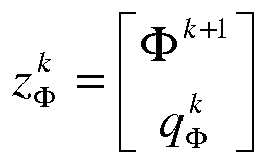
is the solution found for point in time k+1, Φ̃ k+1 being a vector specifying a setpoint specified for said climate related variable at point in time k+1 for at least a part of said plurality of cells, 
are boundary conditions relevant for said climate related variable at point in time k,
S is a selection matrix, selecting cells for said distribution having a setpoint, O is the zero matrix, I is the identity matrix and Q and R are weighting matrices for tracking and energy consumption,
wherein AΦ is a matrix that defines the development of vector Φ as a function of one or more other vectors of climate related variables,
wherein BΦ is a matrix that maps the source terms for field Φ to the cell field values affected by those source terms, and wherein the controller (4) controls the plurality of said actuators in accordance with the source term q Φ.
S is a selection matrix, selecting cells for said distribution having a setpoint, O is the zero matrix, I is the identity matrix and Q and R are weighting matrices for tracking and energy consumption,
wherein AΦ is a matrix that defines the development of vector Φ as a function of one or more other vectors of climate related variables,
wherein BΦ is a matrix that maps the source terms for field Φ to the cell field values affected by those source terms, and wherein the controller (4) controls the plurality of said actuators in accordance with the source term q Φ.
Description
- The present invention relates to a method for controlling an indoor climate.
- The present invention further relates to a data processor for controlling an indoor climate.
- The present invention further relates to system comprising such a data processor.
- The present invention further relates to a system for designing an indoor climate control system.
- The present invention further relates to a method for designing an indoor climate control system.
- The present invention further relates to a computer program product.
- An indoor climate includes various aspects that may have to be controlled, such as temperature, humidity, air movement, and CO2 concentration. An indoor climate is subject to various spatial and temporal dynamics that are in particular determined by air circulation. This phenomenon renders it difficult to provide for a homogeneous setting of climate variables as temperature, humidity, air movement, CO2 concentration in the indoor space for which the climates has to be controlled. As a result of temperature differences, air leakage (through walls, windows, etc.) and forced ventilation (fans, air conditioning etc.) air currents occur. Even a slight change in, for example, the weather conditions, the geometry of the space and the climate installations, may have substantial effects on the flow field and hence on the entire indoor climate.
The spatial dynamics are particularly evident in large open spaces. A greenhouse is a telling example. In a greenhouse of some hectares significant temperature and humidity differences can easily occur that lead to inconsistent quality and growth rate of the crop. As a result of the temperature differences water vapor may locally condense and can cause mold. Condensation of water and the resulting mold may also occur due to a local lack of air movement. Preventing this by air-conditioning systems is power consuming. Providing for additional ventilation, by opening windows for example, reduces the CO2 concentration and also may result in energy losses. - Current climate control systems do not adequately address these problems. According to one known approach a feedback loop is provided that receives input for a climate variable, such as the temperature, from a single sensor and that controls an actuator, e.g. a heater, on the basis of the sensed value for the variable and a set point.
- Modern greenhouses apply zoned climate control. Therein several sensor-loop actuator systems are distributed in the controlled indoor space that operate mutually independent of each other. This can lead to inefficiencies, in particular if sensor-loop actuator systems are provided that control mutually different conditions, such as a temperature and a humidity.
- Climate control arrangements are known that adapt their operation to current and predicted weather conditions outside the controlled indoor space. These arrangements however do not address the dynamical interactions inside the controlled indoor space.
- A common strategy to achieve, particularly in the horticultural industry, a common environment is active mixing of air by artificially induced air flows. Therewith it is attempted to stir the air in order to obtain spatially uniformly distributed climate conditions as temperature and humidity. In practice, however, the effects are usually mediocre. Often natural air flows tend to dominate artificially induced air flows. Moreover, the equipment such as fans used to artificially induce air flows is not properly regulated and tend to be used on a continuous basis regardless the instantaneous state of the indoor climate, therewith consumes a substantial amount of power.
- Computational Fluid Dynamic (CFD) methods are known to simulate the indoor climate given boundary conditions as outside temperature, sun, floor and wall temperatures and source terms such as heaters and air conditioning devices. These methods typically apply a Finite Volume Method (FVM)) wherein the indoor space is discretized into cells, each of which has its own temperature, 3D flow velocity and pressure. For example, in the implementation known as "SIMPLE" (Semi-Implicit Method for Pressure Linked Equations) the following sets of equations for energy, momentum and pressure correction are used. The "SIMPLE" method is described in more detail in: Suhas V. Patankar, "Numerical Heat Transfer and Fluid Flow", ISBN 0-07-1980 048740-S, pp. 126-131. The equations include the following discretized Navier-Stokes equations with an additional energy equation.
Energy:
Momentum


Pressure correction
- Therein the vectors T, u, v, w, P contain the temperature field, the air velocity in x, y, and z directions and pressure field respectively, for time step k+1. The results obtained for k+1 may be one of a series of results being followed by the results for k+2, k+3 etc. Alternatively the results for k+1 may be considered as a steady state solution. In the sequel of this descript the symbol Φ will also be used to denote a field in general and this symbol may be provided with an index referring to a specific type of field. For example

- The vectors û, v̂, ŵ are uncorrected velocity vectors, i.e. velocity vectors that jointly do not meet the law of conservation of mass.
- The vector P' is a pressure correction field. This field serves to correct û, v̂, ŵ into fields u,v,w that do adhere to mass conservation.
- The source terms are denoted by the character "q". E.g. qT is a vector of thermal source terms, like power added through the floor heating and heating and power extracted by the airconditioning. Exogenous inputs or boundary conditions are indicated by the symbol "e", e.g. the outside weather conditions, an opened or closed state of windows etc.
- Each matrix A is of size NxN, with N the amount of cells in the grid. In practice, the amount of cells may range from thousands to millions. Accordingly, these matrices can become very large. They are largely sparse, but their structure can be time dependent. E.g. in the energy equation, not only the entries of AT change as air flow changes, but also their location. I.e. the temperature of a certain cell might depend on the temperature of its left neighbor if u is positive there, but it will depend on the temperature of its right neighbor if the flow changes direction.
- The SIMPLE method solves these 5 sets jointly.This is an iterative method involving the following sequence of steps that is repeated until convergence of the this set of equations occurred.
Step 1: solve u* from
Step 2: update û, with
Step 3: solve v* from
Step 4: update v̂, with
Step 5: solve w* from
Step 6: update ŵ with
Step 7: solve P' from
Step 8: update P with
Step 9: update u,v,w with the correction
Step 10: solve T* from
Step 11: Update T with
In the equations above, the variables xk are the variables for which values are determined for point in time k. The remaining variables are part of the iteration procedure for computation of the result for k+1. As becomes apparent from the above, the joint set of equations can be solved in a sequential manner. Alternatively one or more equations may be solved in a parallel manner. - The known method allows the skilled person to simulate the effect of climate control measures as is illustrated in
FIG. 1A . The skilled person desiring to achieve a particular indoor climate can specify certain control measures according to a design d, such as heaters and air conditioning devices, as well as their settings and simulate the effect thereof on the indoor climate to be controlled. The above-mentioned simulation method, symbolically indicated as block CFD (FVM), then simulates the effect of the specified measures as indicated by the vector x = (T, u, v, w, P) on the indoor climate. Based on this outcome and his expert knowledge the skilled person can choose a new design di+1 and verify if this more closely achieves a desired result. The skilled person may for example verify if the estimated values for the climate variables sufficiently comply with the desired values for those variables and if this is achieved within an available energy budget. In this way the skilled person can by trial and error provide specifications d* for a climate control system that sufficiently achieves the desired indoor climate conditions. - This known method still has a disadvantage that it requires intensive human effort to arrive at a reasonable system specification and that it is not guaranteed that the specifications found in this way indeed provide for a globally optimal solution. Also, this method requires many simulation steps, each of which might require long computation times. Moreover, the known method is not suitable to adapt the settings of the system to the prevailing conditions, the current outdoor temperature, incoming solar radiation, the changes in air flow during a longer period caused by crop growth in the indoor space.
- To overcome this last problem, a real-time control system can be used. Sequential Quadratic Programming (SQP) is a known technique for this purpose. In this method, a cost function J (x, q) = (x - x̃) T Q(x - x̃)+ qTRq is to be minimized by proper choice of q. The optimal q is found by simulating the system with iterant qi, leading to indoor climate xi. Q and R are weighting matrices for tracking and energy consumption respectively The combination (qi,xi) leads to scalar cost Ji. A new iterant qi+1 is found by a gradient descent method. The derivative of J(x,q) to qi is calculated and qi+1 is taken as a function of this derivative. The process stops when there is no significant change between subsequent iterants. The method has the following drawbacks. Firstly, calculating the derivative of J(x,q) to q is generally only possible by numerical approximation and this requires much computational effort. Secondly, the method requires multiple simulation steps to be performed. Since simulation steps are computationally expensive it is likely that this method will not be able to run in real-time. Various efforts exist for simplifying the approximation of the derivative, for instance with the Adjoint SQP method as schematically illustrated in
FIG. 1B , but the requirement of multiple simulation steps remains. Accordingly, there is a need for improvement. - It is a first object of the present invention to provide a data processor that renders it possible to at least alleviate one or more of these problems. In accordance therewith a data processor is provided as claimed in
claim 1. - It is a second object of the present invention to provide a climate control system that at least alleviate one or more of these problems.
- In accordance therewith a climate control system is provided as claimed in claim 3.
- It is a third object of the present invention to provide a design system including the data processor that renders it possible to at least alleviate one or more of these problems.
- In accordance therewith a design system is provided as claimed in claim 7. It is a fourth object of the present invention to provide a data processing method that renders it possible to at least alleviate one or more of these problems. In accordance therewith a data processing method is provided as claimed in claim 8.
- It is a fifth object of the present invention to provide a climate control method that at least alleviates one or more of the problems identified above.
- In accordance therewith a method is provided as claimed in claim 9.
- It is a sixth object of the present invention to provide a design method that at least alleviates one or more of the problems identified above. In accordance therewith a method is provided as claimed in claim 14.
- It is a seventh object of the present invention to provide a computer program product comprising a computer program, which when executed by a programmable processor enables the programmable processor to at least alleviate one or more of the problems identified above.
- In accordance therewith a computer program product is provided as claimed in claim 15.
- According to the present invention a method is provided that jointly resolves a set of coupled optimization problems of the following form:


Therein,


time k+ 1. As the values for the source terms are obtained as a solution of a linearly constrained quadratic problem, it is guaranteed that the found solution is indeed the globally optimal solution that could be reached. The results obtained for k may be one of a series of results being followed by the results for k+1, k+2 etc. Alternatively the results for k+1 may be considered as a steady state solution. - As recognized by the inventor the following approach of the problem of properly controlling an indoor climate is possible is based on the introduction of an augmented state vector

- Therein vector Φ specifies the field to be controlled and q Φ comprises the source terms for that field to be optimized. In the following way this enables a redefinition of the optimization problem.
- In a first step, the energy equation (1) is rewritten as follows:
- When written out (arguments for the components of matrix AT and for the components of vector bT not shown)
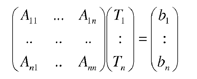
- The vector


- The boundary conditions "e" may be provided in various ways. In an embodiment the walls enclosing the indoor space are represented by cells in the model, and the boundary conditions are the conditions prevailing outside the walls, such as the weather conditions. Alternatively, the walls may not be represented by cells in the model and the wall temperatures may be part of the boundary conditions.
- Substituting this in equation (1) gives the following result :

- Therewith the original problem can be rewritten as an optimization problem in an n+m dimensional space (which has an only modestly increased dimension) wherein a state, for example the state of the temperature field is represented by a state vector


- Therein

- The energy equation is then rewritten as an optimization problem, as follows:

Subject to
Therein ST is a pattern matrix selecting those cells having a thermal setpoint, I is the identity matrix, O is the 0 matrix and

- Similarly, the three equations for the momentum can be replaced by the equations 8a, 8b, 9a, 9b and 10a, 10c below. Therein the functions bu(), bv(), bw() are rewritten as a linear combination in a manner similarly to those presented for the energy equation. It is noted that the vector bw() is also a function of the temperature T.



Subject to:

Subject to:
Furthermore the equation for calculating the pressure p is rewritten as
Subject to:
- The pattern matrix


- It is noted that for those fields that are not directly controlled, the linearly constrained quadratic optimization problem reduces to a linear equation. By way of example the climate variable fields u,v,w may be directly controlled by fans, while the pressure field P is indirectly affected by these actuators. As indicated above, the weighting matrices QΦ and RΦ, which may be changed as a function of time, respectively specify the relative importance that is attached to the accuracy with which the solution approaches the specified setpoint and the degree to which the solution complies with energy consumption budgets. A weighting matrix QΦ is also denoted as a tracking matrix as it influences the tracking of the setpoints specified for the relevant field Φ. This matrix usually only has entries on the diagonal. Having a higher entry on a particular element of the diagonal w.r.t, the other elements on the diagonal means that the climate control system will focus more on the setpoint corresponding to that matrix element. Also RΦ will typically be diagonal, for example in the form of a scaled identity matrix with one scalar scaling factor. These matrices may have a predetermined values but alternatively an operator may be allowed to changes these matrices. For example, in a greenhouse accommodating a climate sensitive crop the weighting matrix QΦ may be specified that guarantees that the controlled field accurately matches the specified field. Alternatively, if it is known that a relatively insensitive crop is grown and a low energy consumption is desired the weighting matrix RΦ may be specified in accordance with this desire. The setting of the weighting matrices for the various fields may differ. For example, because given a certain energy budget a field Φ1 may be more easily controlled to match the setpoint than another field Φ2. In an embodiment the user may have a control input to set the scalar scaling factor referred to above to tune the climate control system between 'quality' and 'eco' mode. The matrices QΦ and RΦ may be set as a function of time, in which they are denoted as

- It is noted that the climate control method, climate control system and the data processor serving as a controller therein can either be used in a steady state mode or in a dynamic mode. In the dynamic mode the setpoints for the climate related variables and/or the values of the boundary conditions may change as a function of time. In the steady state mode, the setpoints for the climate related variables as well as the values of the boundary conditions are presumed constant. As the steady state solution is independent on the initial state of the indoor climate the steady state operational mode does not require a measurement facility to measure the state. Nor are processing facilities required to process the measured values. For the equations 7b, 8b, 9b, 10b, 11b this implies that the matrices Bx are zero matrices for the respective variables T,u,v,w and P indicated by x. The steady state solution will indicate the source terms with which the climate control system will eventually reach the setpoints. (This may be on a large time scale)
- It is noted that the climate control system may be operated according to various use modes. In one of these use modes the vector Φ specifying a setpoint and the boundary conditions


- Alternatively, predicted values may be used to even better respond to changing circumstances. I.e. according to this alternative the set of equations is jointly resolved for a plurality of time steps and based on predicted values for the vector Φ̃ specifying the setpoint and/or the boundary conditions

- These and other aspects are described in more detail with reference to the drawing. Therein:
-
FIG. 1A schematically shows a prior art method for designing an indoor climate control system, -
Fig 1B : schematically shows a prior art method for real-time control of an indoor climate, -
FIG. 2 schematically shows an embodiment of a climate control system according to the first aspect of the present invention, -
FIG. 3 shows a data processor according to the second aspect of the invention for use in a climate control system according to the first aspect of the invention, -
FIG. 4 shows an embodiment of a module of the data processor according toFIG. 3 , -
FIG. 5 shows an embodiment of another module of the data processor according toFIG. 3 , -
FIG. 6 shows an embodiment of again another module of the data processor according toFIG. 3 , -
FIG. 7A, 7B schematically show parts of the data processor according toFIG. 3 , -
FIG. 8 shows a control method according to the third aspect of the present invention, -
FIG. 9 shows a design system according to the present invention. - Like reference symbols in the various drawings indicate like elements unless otherwise indicated.
-
FIG. 2 schematically shows aclimate control system 1 for controlling a climate in anindoor space 10. The climate control system comprises a plurality ofsensors 2a, ...2ns to sense climate related variables in said indoor space, and to provide sensory data Sa, ..Sn indicative for sensed values for said variables. The climate control system further comprises a plurality ofactuators 3a, ...,3na for controlling climate related variables in said environment. Adata processor 4, here serving as a controller controls theactuators 3a,...,3na on the basis of the sensory data Sa, ..Sns. To that end thecontroller 4 jointly resolves a set of coupled optimization problems of the following form.:
Subject to
Therein,

- Furthermore, AΦ is a matrix that defines the development of a vector Φ as a function of one or more other vectors of climate related variables and BΦ is a matrix that maps the source terms for field Φ to the cell field values affected by those source terms. The controller controls the plurality of the
actuators 3a to 3m in accordance with the source term q Φ found by resolving the above-mentioned optimization problem. - The
climate control system 1 may control one or more variables s of the indoor climate in theindoor space 10. Example of said variables, are a temperature distribution, a pressure distribution, flow fields, an air humidity distribution etc. Theactuators 3a,...,3na of theclimate control system 1 to control one or more of these variables may include for example one or more of heaters, air-conditioners, ventilators, pumps, humidifiers, dryers, etc. Thesensors 2a,...,2n used to measure a current state of the climate may include thermal sensors, flow sensors, pressure sensors, air humidity sensors etc. - Typically, the number of
sensors 2a,...,2n is less than the number of cells involved in the computation. In the embodiment shown, theclimate control system 1 further includes amapping unit 5 that estimates a current value of a field for each cell on the basis of the sensed values for the field as obtained from the sensors. Themapping unit 5 may for example provide the estimation on the basis of an interpolation of sensed values. - In the embodiment the
controller 4 and themapping unit 5 are programmable devices. In this case thesystem 1 as shown includes acomputer program product 6 that comprises a program for controlling thecontroller 4 and themapping unit 5. Alternatively, thecontroller 4 and/or themapping unit 5 may be provided as dedicated hardware or as a combination of dedicated hardware and programmable elements. - An embodiment of the
controller 4 is shown in more detail inFIG. 3 . Dependent on the number of climate variables that have to be controlled, thecontroller 4 may include a different number of modules that are mutually inter connected. In the embodiment shown thecontroller 4 comprises atemperature monitor module 41, a first, a second and a thirdflow monitor module pressure monitor module 45. These modules each include a preparation unit (411, 421, 431, 441 and 451 respectively), a solve unit (412, 422, 432, 442 and 452 respectively), and an update unit (413, 423, 433, 443 and 453 respectively). Embodiments of these modules are described with reference toFIG. 4 ,5 and6 . ThereinFIG. 4 shows thetemperature monitor module 41 in more detail.FIG. 5 shows the firstflow monitor module 42 in more detail. The other twoflow monitor modules flow monitor module 41. However, in the thirdflow monitor module 44 the components of the vector b'w are also dependent on the temperature field to take into account buoyant convection effects.FIG. 6 shows the pressuredata processing module 45 in more detail. - The controller further includes a
correction module 46 that corrects the flow fields estimated by theflow monitor modules - The
controller 4 further includes asource mapping module 47 that generates matrix data that map the source terms to the variables directly actuated by the actuators represented by the source terms. - The
controller 4 further includes aninput module 48, enabling a user to control operation of the system. - The
controller 4 further comprisesdatapath facilities datapath control elements - Operation of the
controller 4 in thesystem 1 is now described with reference to a flow chart shown inFIG. 8 . The flow chart illustrates an iterative procedure with which the values for the source terms that are required to approach the specified set points for climate related variables. Upon convergence of the procedure the values for the source terms for a time step k become available, and the procedure can be repeated to determine the source term values for the next time step k+1.
In the embodiment shown thecontroller 4 is arranged as a programmable general purpose processor. Thecontroller 4 is coupled tomemory 6 comprising a computer program that causes the programmable processor to carry out the climate control method.
In an optional first step S1 all variables are assigned an estimated or known initial value where possible. Variables for which a value is not known or can be estimated, are assigned a random value. If available, however, the known or estimated value should be used to obtain a more rapid convergence. In the embodiment ofFIG. 3 , this is achieved by transferring the initial values via data path controlelement 491, responsive to signal "k=0", to aresults bus 4R. Subsequently these values are gated to the iterands bus 4I by data path controlelement 492, responsive to signal "init". - If values are available that are obtained in a previous time step k, it suffices to gate these values to the iterands bus 4I by data path control
element 492. - Subsequently the sequence of steps S2-S11 is iterated until convergence is detected in step S12. Therewith the results for the next time step k+1 are obtained.
- In step S2 the value for

unit 422 of flowdata processing module 42. The value
- Schematically it is shown that the solve
unit 422 has two mutually cooperatingparts part 4221 searches for the value
part 4222 restricts the possible solutions to the linear constraint set by equation 7b.Parts part 4222. In practice however, different implementations are possible and known to solve a linearly constrained quadratic problem. - The matrices Su, Qu and Ru, as well as the set point for ũ for the field u are provided by the
user input module 48. The matrix Bu is provided bysource mapping module 47 viabus 4B. The vector
preparation part 4221 from the flow field uk and the prevailing boundary conditions

Part 4212 ofpreparation unit 421 calculates matrix A from the current values of the iterands u,v,w and P available on iterand bus 4I. - The optimum value

unit 422 is provided to theupdate unit 423. - In step S3 the update unit 423 (having
adder 4231 and storage element 4232) uses this value

- Therein α is a relaxation parameter, which is for example selected in the range of 0 to 1, preferably in the range of 0.1 to 0.6, for example a value of about 0.4.
- Similarly, flow
data processing module 43 calculates the value for

- The
units data processing module 43 correspond to theunits data processing module 42. Similarly, flowdata processing module 44 calculates the value for

- The
units data processing module 44 correspond to theunits data processing module 42. - The
unit 441 of flowdata processing module 44 corresponds to theunits 421 of flowdata processing module 42 except for the fact that the part ofpreparation unit 441 that corresponds to thepart 4112 ofpreparation unit 411 differs in that it also uses the current value of the iterand T for the calculation of vector b'w. This is because a relatively strong relationship exists between flows in a vertical direction and the temperature distribution. - It is noted that in the embodiment shown the corrected values u,v,w of the iterands for the flow fields as determined by
correction module 46 are used for the calculation of the matrices Au, Av, Aw. However, in an alternative embodiment, the uncorrected values û, v̂, ŵ may be used instead to calculate these matrices, as upon convergence, the corrected and uncorrected velocities are equal to each other. This may however slightly slow down convergence. - Next in step S8 temperature
data processing module 41 calculates the value for

In the embodiment shown the solveunit 412 havingparts 
Parts preparation unit 411 respectively calculate the vector b'T and matrix AT used by the solveunit 412. The update step is conducted byupdate unit 413 having anadder 4131 and astorage element 4132 for storing the value zT. - These calculations substantially correspond to those described for the calculations relating to the flow fields u, v, w described above. Also the components of the temperature
data processing module 41 as shown inFIG. 4 correspond to those of the flowdata processing module 42 as shown inFIG. 5 . Therein components of the temperaturedata processing module 41 that correspond to those of the flowdata processing module 42 are referred by a reference number having a second digit that is 1 instead of 2. - Next in step S10 the value for P' is calculated as follows:

Parts - In the present embodiment, the pressure P is not actively controlled. Accordingly, it suffices to solve the above-mentioned linear equation. Hence the solve
unit 452 of the pressure data processing module only has a linearequation solving part 4522 as schematically illustrated inFIG. 6 . Nevertheless in other embodiments the pressure P may be actively controlled. In that case the solveunit 452 of the pressure data processing module may also have an optimization part 4521 analogous to those used in the flow data processing modules and the temperature data processing modules. - And in step S11 the value for P is updated by update unit 453 (having
adder 4331 and a storage element 4332 for the value P) as:
- Therein αP is a relaxation parameter, which is for example selected in the range of 0 to 1, preferably in the range of 0.1 to 0.6, for example a value of about 0.4.
- The above-mentioned steps may also be performed according to another sequence, provided that the update step follows the step for calculating the *value for the estimated optimum.
- The above-mentioned steps are followed by a correction step S12 involving the following calculation for updating the values for u,v and w:

- This correction step is described in more detail in: Suhas V. Patankar, "Numerical Heat Transfer and Fluid Flow", ISBN 0-07-1980 048740-S, pp. 123-134.
- In the embodiment of the
controller 4 shown inFIG. 3 , this correction step is performed by thecorrection module 46. - In Step S13 it is verified whether the procedure has converged or not. Verification may take place, for example by comparing the differences between the updated values for the variables to be optimized and their previous values

- According to a more reliable test it is verified if the previously found values for the state vector

- I.e. it is verified if

- Additionally to verify the convergence of the pressure equation it is determined if the computational error of mass conservation is less than a predetermined threshold value ηP. In the embodiment shown this is verified by the circuit shown in
FIG. 7A , which generates the signal Ep = True iff
- The procedure terminates if the verifications indicate for each of the equations that convergence has occurred, otherwise a following iteration is performed. To that
end control element 494, as shown in more detail inFIG. 7B is arranged to issue a signal "k++" indicating global convergence if each of the converge indication signals ET, Eu,Ev, Ew, Ep from the respective field data processing modules 41-45 indicates that convergence occurred for the corresponding monitored field. In response to the signal "k++", the iterand values present onbus 4C are transferred toresults bus 4R. The source terms q Φ that are transferred as part of the transferred iterand values than can be used for control the actuators at point in time k. - Upon detection of global convergence the values of the iterands for the various augmented state vectors zu, zv, zw, zT, zP are transmitted from the iterand bus 4I via
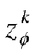
gate 493 as the results
results bus 4R. Therein the terms
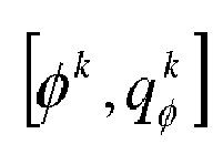


actuators 3a, ..., 3m. - At the next point in time k, the source terms


- A further embodiment is now described which does not only take into account but also uses predicted input values for the boundary conditions, e.g. based on a weather forecast. In this way the controller may better anticipate to changes of said boundary conditions and/or with more modest energy requirements. This is in particular attractive for control of the temperature as the temperature field of an indoor space reacts relatively slowly to a change in the source settings unless high amounts of energy are allowed.
- In this embodiment the augmented state vector

- Therein the value k' denotes the number of time steps that is included in the prediction. For k' = 0, the predictive augmented state vector reduces to the augmented state vector, i.e.:

- The optimization problem to be resolved is now generalized to:

Subject to
- The matrices k'S Φ ,k'O,k'I,k'Q Φ ,k'R Φ used in the upper equation are obvious extensions to the matrices S Φ, O, I, Q Φ , R Φ used in equation 5a.
- Furthermore the matrices


- Therein:

Hence:
And
- A system, method and controller analogous to those disclosed above, with reference to
FIG. 2-8 , can be used to perform the above-mentioned optimization -
FIG. 9 shows a design system according to the present invention. The design system comprises adata processor 4 similar to thedata processor 4 as described with reference toFIG. 2-8 . - During operation the following steps are performed. In a way analogous to the method described with reference to
FIG. 8 , a set of values for controlling an indoor climate are calculated. Contrary to the situation as described with reference toFIG. 8 however, the values are not used for actual control of actuators, but to simulate the effect of actuators in a model of the indoor climate for which the control system is to be designed. On its turn, the simulated values of the climate related variables that are achieved therewith are provided as input data to the method, instead of using sensed values. The control values qk that are obtained upon global convergence of the procedure are an indication for the resources that are to be used in an actual control system. For example if it follows from the design process that a certain simulated actuator requires a certain amount of power to achieve the setpoints, it follows that the actuator in question should at least be capable of operation in that power range. Alternatively if it becomes apparent that a certain simulated actuator requires no power at all, it may be concluded that the actuator is not necessary. - As will be apparent to a person skilled in the art, the elements listed in the claims related to the system and the data processor are meant to include any hardware (such as separate or integrated circuits or electronic elements) or software (such as programs or parts of programs) which reproduce in operation or are designed to reproduce a specified function, be it solely or in conjunction with other functions, be it in isolation or in co-operation with other elements. The invention can be implemented by means of hardware comprising several distinct elements, and by means of a suitably programmed computer. Various steps may be implemented in a sequential manner, but may alternatively be implemented in parallel.
- In the apparatus claim enumerating several means, several of these means can be embodied by one and the same item of hardware. For example in the design system the
data processor 4 and the simulation processor 8 may be formed by a single hardware item. Such a hardware item may for example alternately compute the data processing steps described in claim 8, and the additional simulation steps described inclaim 10. 'Computer program product' is to be understood to mean any software product stored on a computer-readable medium, such as a floppy disk, downloadable via a network, such as the Internet, or marketable in any other manner.
Claims (15)
- A data processor (4), the data processor comprising inputs to receive input data (Sa, ..Sns) indicative for values of indoor climate related variables and comprising outputs to provide control signals (Ca,...,Cna) suitable for control of the indoor climate related variables on the basis of said input data (Sa, ..Sns), wherein said data processor jointly resolves a set of coupled optimization problems of the following form

subject to
wherein:


wherein BΦ is a matrix that maps the source terms for field Φ to the cell field values affected by those source terms, and wherein the data processor provides the control signals (Ca,...,Cna) in accordance with the source term q Φ. - The data processor (4) according to claim 1, wherein jointly resolving the set of coupled optimization problems involves the following steps:- An update step, comprising the following sub-steps to be carried out in arbitrary order- update (S1u) the air velocity field u and associated source term field qu for a first spatial direction (x) by optimizing the air velocity field u for said direction,- update (S1v) the air velocity field v and associated source term field qv for a second spatial direction (y) by optimizing the air velocity field v for said direction,- update (S1w) the air velocity field w and associated source term field qw for a third spatial direction (z) by optimizing the air velocity field z for said direction,- update (S1T) the temperature field T and associated source term field qT by optimizing the temperature field T,- Calculate (S2) the pressure field (P)- Apply a relaxation step (S3),- Check for convergence, otherwise repeat the previous steps S1-S3
- Climate control system (10) for controlling a climate in an indoor space (10), comprising a data processor as claimed in claim 1 or 2, the climate control system further comprising- a plurality of sensors (2a, ...2n) to sense climate related variables in said indoor space, and to provide sensory data (Sa, ..Sn) indicative for sensed values for said variables as the input data (Sa, ..Sns) to said data processor,- a plurality of actuators (3a, ...,3m), for controlling climate related variables in said environment, which actuators are controlled by said data processor (4) in accordance with the source term q Φ.
- Climate control system according to claim 3, further comprising a mapping unit (5) for mapping said sensory data onto the plurality of cells.
- Climate control system according to claim 3 or 4, wherein the vector Φ̃ specifying the setpoint for said climate related variable for at least a part of said plurality of cells is uniform.
- Climate control system according to claim 3 or 4, wherein the vector Φ̃ specifying the setpoint for said climate related variable for at least a part of said plurality of cells is non-uniform.
- A design system comprising a data processor (4) according to claim 1 or 2, wherein the source terms (qk) calculated by the design system in response to the provided setpoint values (Φ̃ k ) and boundary conditions

- A data processing method relating to control of a climate in an indoor space (10), the data processing method comprising- receiving data (Sa, ..Sn) indicative for values of indoor climate related variables,- jointly resolving a set of coupled optimization problems of the following form:

subject to
wherein:
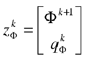

the method further comprising providing control signals in accordance with said source terms. - A method according to claim 8, further comprising- receiving sensory data (Sa, ..Sn) indicative for sensed values from climate related variables in an indoor space as the data indicative for values of indoor climate related variables,
driving a plurality of actuators (3a,...,3m) by said control signals (Ca,...Cna) - The method according to claim 9, comprising providing the vector Φ̃ specifying a setpoint and the boundary conditions

- The method according to claim 9, comprising providing the vector Φ̃ specifying a setpoint and/or the boundary conditions

- The method according to claim 11, comprising jointly resolving the set of equations for one time step at a time.
- The method according to claim 11, comprising jointly resolving the set of equations for a plurality of time steps and based on predicted values for the vector Φ̃ specifying the setpoint and/or the boundary conditions

- The method according to claim 8, wherein the source terms (qk) that are calculated in response to the provided setpoint values (Φ̃ k ) and boundary conditions

- A computer program product (6) comprising a computer program, which when executed by a programmable processor causes the programmable processor to carry out any of the steps of the method of claim 8.
Priority Applications (4)
| Application Number | Priority Date | Filing Date | Title |
|---|---|---|---|
| EP14158662.8A EP2919078A1 (en) | 2014-03-10 | 2014-03-10 | Navier-Stokes based indoor climate control |
| EP15715477.4A EP3117275B1 (en) | 2014-03-10 | 2015-03-10 | Navier-stokes based indoor climate control |
| PCT/NL2015/050150 WO2015137803A1 (en) | 2014-03-10 | 2015-03-10 | Navier-stokes based indoor climate control |
| US15/123,706 US10208971B2 (en) | 2014-03-10 | 2015-03-10 | Navier-stokes based indoor climate control |
Applications Claiming Priority (1)
| Application Number | Priority Date | Filing Date | Title |
|---|---|---|---|
| EP14158662.8A EP2919078A1 (en) | 2014-03-10 | 2014-03-10 | Navier-Stokes based indoor climate control |
Publications (1)
| Publication Number | Publication Date |
|---|---|
| EP2919078A1 true EP2919078A1 (en) | 2015-09-16 |
Family
ID=50287876
Family Applications (2)
| Application Number | Title | Priority Date | Filing Date |
|---|---|---|---|
| EP14158662.8A Withdrawn EP2919078A1 (en) | 2014-03-10 | 2014-03-10 | Navier-Stokes based indoor climate control |
| EP15715477.4A Active EP3117275B1 (en) | 2014-03-10 | 2015-03-10 | Navier-stokes based indoor climate control |
Family Applications After (1)
| Application Number | Title | Priority Date | Filing Date |
|---|---|---|---|
| EP15715477.4A Active EP3117275B1 (en) | 2014-03-10 | 2015-03-10 | Navier-stokes based indoor climate control |
Country Status (3)
| Country | Link |
|---|---|
| US (1) | US10208971B2 (en) |
| EP (2) | EP2919078A1 (en) |
| WO (1) | WO2015137803A1 (en) |
Cited By (2)
| Publication number | Priority date | Publication date | Assignee | Title |
|---|---|---|---|---|
| JP2018155729A (en) * | 2016-12-23 | 2018-10-04 | ロレックス・ソシエテ・アノニムRolex Sa | Clock button |
| CN110848896A (en) * | 2019-11-12 | 2020-02-28 | 深圳孚沃德斯科技有限公司 | Intelligent energy-saving control system and method for air conditioner cooling system based on neural network |
Families Citing this family (2)
| Publication number | Priority date | Publication date | Assignee | Title |
|---|---|---|---|---|
| WO2021194369A1 (en) * | 2020-03-27 | 2021-09-30 | Siemens Schweiz Ag | Computerized device and computer-implemented method for controlling a hvac system |
| CN114508784B (en) * | 2022-02-16 | 2024-09-24 | 重庆邮电大学 | Multi-source complementary heating system and optimal control method thereof |
Citations (3)
| Publication number | Priority date | Publication date | Assignee | Title |
|---|---|---|---|---|
| US20130035794A1 (en) * | 2011-08-03 | 2013-02-07 | Behzad Imani | Method and system for controlling building energy use |
| US20130144444A1 (en) * | 2010-08-25 | 2013-06-06 | Schneider Electric Industries Sas | Method for determining parameters for controlling an hvca system |
| WO2013130956A1 (en) * | 2012-03-02 | 2013-09-06 | Vigilent Corporation | Multi-dimensional optimization for controlling environmental maintenance modules |
Family Cites Families (48)
| Publication number | Priority date | Publication date | Assignee | Title |
|---|---|---|---|---|
| US7542885B1 (en) * | 1999-05-07 | 2009-06-02 | The United States Of America As Represented By The Administrator Of The National Aeronautics And Space Administration | Method and apparatus for predicting unsteady pressure and flow rate distribution in a fluid network |
| US6698663B2 (en) * | 2002-02-04 | 2004-03-02 | Delphi Technologies, Inc. | Model-based method of generating control algorithms for an automatic climate control system |
| US6718277B2 (en) * | 2002-04-17 | 2004-04-06 | Hewlett-Packard Development Company, L.P. | Atmospheric control within a building |
| US7114555B2 (en) * | 2002-05-31 | 2006-10-03 | Hewlett-Packard Development Company, L.P. | Controlled cooling of a data center |
| US20040254686A1 (en) * | 2003-05-28 | 2004-12-16 | Masaru Matsui | Energy consumption prediction apparatus and energy consumption prediction method |
| US7031870B2 (en) * | 2004-05-28 | 2006-04-18 | Hewlett-Packard Development Company, L.P. | Data center evaluation using an air re-circulation index |
| DE102005006410A1 (en) * | 2005-02-11 | 2006-08-17 | Siemens Ag | Method for optimizing the operation of several compressor units and apparatus for this purpose |
| US7881910B2 (en) * | 2005-05-02 | 2011-02-01 | American Power Conversion Corporation | Methods and systems for managing facility power and cooling |
| US20070055392A1 (en) * | 2005-09-06 | 2007-03-08 | D Amato Fernando J | Method and system for model predictive control of a power plant |
| US7389151B2 (en) * | 2006-03-06 | 2008-06-17 | General Electric Company | Systems and methods for multi-level optimizing control systems for boilers |
| US7558649B1 (en) * | 2006-05-03 | 2009-07-07 | Hewlett-Packard Development Company, L.P. | Method for predicting airflow rates |
| US7644051B1 (en) | 2006-07-28 | 2010-01-05 | Hewlett-Packard Development Company, L.P. | Management of data centers using a model |
| US7620613B1 (en) * | 2006-07-28 | 2009-11-17 | Hewlett-Packard Development Company, L.P. | Thermal management of data centers |
| US7676280B1 (en) * | 2007-01-29 | 2010-03-09 | Hewlett-Packard Development Company, L.P. | Dynamic environmental management |
| US7904209B2 (en) * | 2007-03-01 | 2011-03-08 | Syracuse University | Open web services-based indoor climate control system |
| US7991488B2 (en) * | 2007-03-29 | 2011-08-02 | Colorado State University Research Foundation | Apparatus and method for use in computational fluid dynamics |
| US8224489B2 (en) * | 2008-03-03 | 2012-07-17 | Federspiel, Corporation | Method and apparatus for coordinating the control of HVAC units |
| US8209056B2 (en) * | 2008-11-25 | 2012-06-26 | American Power Conversion Corporation | System and method for assessing and managing data center airflow and energy usage |
| JP5218279B2 (en) * | 2009-05-21 | 2013-06-26 | 富士通株式会社 | Panel aperture ratio calculation device, panel aperture ratio calculation method, and panel aperture ratio calculation program |
| US8436489B2 (en) * | 2009-06-29 | 2013-05-07 | Lightsail Energy, Inc. | Compressed air energy storage system utilizing two-phase flow to facilitate heat exchange |
| US8196395B2 (en) * | 2009-06-29 | 2012-06-12 | Lightsail Energy, Inc. | Compressed air energy storage system utilizing two-phase flow to facilitate heat exchange |
| JP5492522B2 (en) * | 2009-10-21 | 2014-05-14 | アズビル株式会社 | Air conditioning control apparatus and method |
| US8639651B2 (en) * | 2009-10-30 | 2014-01-28 | Hewlett-Packard Development Company, L. P. | Manipulating environmental conditions in an infrastructure |
| US9086488B2 (en) * | 2010-04-20 | 2015-07-21 | Michigan Aerospace Corporation | Atmospheric measurement system and method |
| US8352085B2 (en) * | 2010-04-29 | 2013-01-08 | Hewlett-Packard Development Company L.P. | Distribution of cooling resources using hierarchically identified cooling microgrids |
| US8504175B2 (en) * | 2010-06-02 | 2013-08-06 | Honeywell International Inc. | Using model predictive control to optimize variable trajectories and system control |
| JP5525960B2 (en) * | 2010-08-10 | 2014-06-18 | アズビル株式会社 | Air conditioning control apparatus and method |
| US8996180B2 (en) * | 2010-09-17 | 2015-03-31 | Schneider Electric It Corporation | System and method for predicting perforated tile airflow in a data center |
| US20120072181A1 (en) | 2010-09-22 | 2012-03-22 | Behzad Imani | Method and apparatus for optimizing hvac systems in buildings |
| GB2483887B (en) * | 2010-09-23 | 2013-01-09 | 4Energy Ltd | Air flow estimation |
| US20120078417A1 (en) * | 2010-09-28 | 2012-03-29 | International Business Machines Corporartion | Detecting Energy and Environmental Leaks In Indoor Environments Using a Mobile Robot |
| US8744631B2 (en) * | 2011-01-28 | 2014-06-03 | Hewlett-Packard Development Company, L.P. | Manipulating environmental conditions in an infrastructure |
| US9176483B2 (en) * | 2011-05-10 | 2015-11-03 | International Business Machines Corporation | Unified and flexible control of multiple data center cooling mechanisms |
| JP5793350B2 (en) * | 2011-06-14 | 2015-10-14 | アズビル株式会社 | Air conditioning control apparatus and method |
| US20120323382A1 (en) * | 2011-06-15 | 2012-12-20 | Expanergy, Llc | Systems and methods to assess and optimize energy usage for a facility |
| US8725307B2 (en) * | 2011-06-28 | 2014-05-13 | Schneider Electric It Corporation | System and method for measurement aided prediction of temperature and airflow values in a data center |
| US8755943B2 (en) * | 2011-09-30 | 2014-06-17 | Johnson Controls Technology Company | Systems and methods for controlling energy use in a building management system using energy budgets |
| AU2011383986B2 (en) * | 2011-12-23 | 2017-04-20 | Schneider Electric It Corporation | Dropped ceiling system cooling prediction |
| WO2013145810A1 (en) * | 2012-03-26 | 2013-10-03 | 三菱電機株式会社 | Air conditioner control device and air conditioner control program |
| US9122261B2 (en) * | 2012-04-24 | 2015-09-01 | Honeywell International Inc. | Apparatus and method for real-time sequential quadratic programming in industrial process control systems |
| JP5973829B2 (en) * | 2012-08-01 | 2016-08-23 | アズビル株式会社 | Air conditioning control apparatus and method |
| JP5973830B2 (en) * | 2012-08-01 | 2016-08-23 | アズビル株式会社 | Air conditioning control solution display device and method |
| US8996193B2 (en) * | 2012-08-20 | 2015-03-31 | International Business Machines Corporation | Computer room cooling control |
| JP6216390B2 (en) * | 2012-11-30 | 2017-10-18 | レンセレイアー ポリテクニック インスティテュート | Method and system for modifying air flow in a building structure |
| US9791872B2 (en) * | 2013-03-14 | 2017-10-17 | Pelco, Inc. | Method and apparatus for an energy saving heating, ventilation, and air conditioning (HVAC) control system |
| US10101048B2 (en) * | 2013-03-15 | 2018-10-16 | Honeywell International Inc. | Supervisory controller for HVAC systems |
| US9529641B2 (en) * | 2013-08-26 | 2016-12-27 | Cisco Technology, Inc. | Data center thermal model |
| US9753892B2 (en) * | 2014-02-20 | 2017-09-05 | Mitsubishi Electric Research Laboratories, Inc. | Method for solving quadratic programs for convex sets with linear equalities by an alternating direction method of multipliers with optimized step sizes |
-
2014
- 2014-03-10 EP EP14158662.8A patent/EP2919078A1/en not_active Withdrawn
-
2015
- 2015-03-10 US US15/123,706 patent/US10208971B2/en active Active
- 2015-03-10 EP EP15715477.4A patent/EP3117275B1/en active Active
- 2015-03-10 WO PCT/NL2015/050150 patent/WO2015137803A1/en not_active Ceased
Patent Citations (3)
| Publication number | Priority date | Publication date | Assignee | Title |
|---|---|---|---|---|
| US20130144444A1 (en) * | 2010-08-25 | 2013-06-06 | Schneider Electric Industries Sas | Method for determining parameters for controlling an hvca system |
| US20130035794A1 (en) * | 2011-08-03 | 2013-02-07 | Behzad Imani | Method and system for controlling building energy use |
| WO2013130956A1 (en) * | 2012-03-02 | 2013-09-06 | Vigilent Corporation | Multi-dimensional optimization for controlling environmental maintenance modules |
Non-Patent Citations (4)
| Title |
|---|
| JIRI CIGLER ET AL: "Subspace identification and model predictive control for buildings", CONTROL AUTOMATION ROBOTICS&VISION (ICARCV), 2010 11TH INTERNATIONAL CONFERENCE ON, IEEE, 7 December 2010 (2010-12-07), pages 750 - 755, XP031900045, ISBN: 978-1-4244-7814-9, DOI: 10.1109/ICARCV.2010.5707821 * |
| SUHAS V. PATANKAR, NUMERICAL HEAT TRANSFER AND FLUID FLOW, 1 January 1981 (1981-01-01), pages 126 - 131, XP002728327, ISBN: 0070487405 * |
| SUHAS V. PATANKAR, NUMERICAL HEAT TRANSFER AND FLUID FLOW, pages 123 - 134 |
| SUHAS V. PATANKAR, NUMERICAL HEAT TRANSFER AND FLUID FLOW, pages 126 - 131 |
Cited By (2)
| Publication number | Priority date | Publication date | Assignee | Title |
|---|---|---|---|---|
| JP2018155729A (en) * | 2016-12-23 | 2018-10-04 | ロレックス・ソシエテ・アノニムRolex Sa | Clock button |
| CN110848896A (en) * | 2019-11-12 | 2020-02-28 | 深圳孚沃德斯科技有限公司 | Intelligent energy-saving control system and method for air conditioner cooling system based on neural network |
Also Published As
| Publication number | Publication date |
|---|---|
| EP3117275B1 (en) | 2022-09-21 |
| EP3117275A1 (en) | 2017-01-18 |
| US10208971B2 (en) | 2019-02-19 |
| US20170074535A1 (en) | 2017-03-16 |
| WO2015137803A1 (en) | 2015-09-17 |
Similar Documents
| Publication | Publication Date | Title |
|---|---|---|
| EP3137865B1 (en) | System and method for monitoring a state of a fluid in an indoor space as well as a climate control system | |
| Picard et al. | Impact of the controller model complexity on model predictive control performance for buildings | |
| JP7693120B2 (en) | CALIBRATION SYSTEM AND METHOD FOR CALIBRATING INDUSTRIAL SYSTEM MODELS USING SIMULATION FAILURE - Patent application | |
| Liao et al. | A simplified physical model for estimating the average air temperature in multi-zone heating systems | |
| Hazyuk et al. | Model Predictive Control of thermal comfort as a benchmark for controller performance | |
| Hu et al. | A state-space modeling approach and multi-level optimization algorithm for predictive control of multi-zone buildings with mixed-mode cooling | |
| EP2998803B1 (en) | Simulation method | |
| EP3265726B1 (en) | Air-conditioning system and system and method for controlling an operation of an air-conditioning system | |
| US7024258B2 (en) | System and method for model-based control of a building fluid distribution system | |
| US20160146491A1 (en) | Building thermal control techniques | |
| US20110022193A1 (en) | Method and apparatus of a self-configured, model-based adaptive, predictive controller for multi-zone regulation systems | |
| EP3117275B1 (en) | Navier-stokes based indoor climate control | |
| Kontes et al. | Intelligent BEMS design using detailed thermal simulation models and surrogate-based stochastic optimization | |
| Sampaio et al. | Simulation and optimal control of heating and cooling systems: A case study of a commercial building | |
| US12571556B2 (en) | Adaptive model predictive control of building HVAC using moving horizon estimation | |
| Rao et al. | Modeling of room temperature dynamics for efficient building energy management | |
| Yu et al. | Comparison of time-invariant and adaptive linear grey-box models for model predictive control of residential buildings | |
| JP2023160722A (en) | Time-varying reinforcement learning for robust adaptive estimator design with application to HVAC flow control | |
| Li et al. | Thermal comfort control based on MEC algorithm for HVAC systems | |
| Reuscher et al. | Control oriented modeling and nonlinear model predictive temperature control of a vehicle cabin | |
| Zhou et al. | Accelerating Reinforcement Learning controller training for building energy management: A hybrid co-simulation approach | |
| US11328099B2 (en) | Thermal model creation device, method, and program of building | |
| Javed et al. | Modelling and optimization of residential heating system using random neural networks | |
| Chen | A methodology for thermal analysis and predictive control of building envelope heating systems | |
| WO2012162332A1 (en) | Control-oriented models for building control and energy management |
Legal Events
| Date | Code | Title | Description |
|---|---|---|---|
| PUAI | Public reference made under article 153(3) epc to a published international application that has entered the european phase |
Free format text: ORIGINAL CODE: 0009012 |
|
| AK | Designated contracting states |
Kind code of ref document: A1 Designated state(s): AL AT BE BG CH CY CZ DE DK EE ES FI FR GB GR HR HU IE IS IT LI LT LU LV MC MK MT NL NO PL PT RO RS SE SI SK SM TR |
|
| AX | Request for extension of the european patent |
Extension state: BA ME |
|
| STAA | Information on the status of an ep patent application or granted ep patent |
Free format text: STATUS: THE APPLICATION IS DEEMED TO BE WITHDRAWN |
|
| 18D | Application deemed to be withdrawn |
Effective date: 20160317 |