EP2919018A1 - Airspeed calculation system for an aircraft - Google Patents
Airspeed calculation system for an aircraft Download PDFInfo
- Publication number
- EP2919018A1 EP2919018A1 EP14198277.7A EP14198277A EP2919018A1 EP 2919018 A1 EP2919018 A1 EP 2919018A1 EP 14198277 A EP14198277 A EP 14198277A EP 2919018 A1 EP2919018 A1 EP 2919018A1
- Authority
- EP
- European Patent Office
- Prior art keywords
- aircraft
- static pressure
- time history
- pressure
- airspeed
- Prior art date
- Legal status (The legal status is an assumption and is not a legal conclusion. Google has not performed a legal analysis and makes no representation as to the accuracy of the status listed.)
- Granted
Links
Images


Classifications
-
- G—PHYSICS
- G01—MEASURING; TESTING
- G01P—MEASURING LINEAR OR ANGULAR SPEED, ACCELERATION, DECELERATION, OR SHOCK; INDICATING PRESENCE, ABSENCE, OR DIRECTION, OF MOVEMENT
- G01P5/00—Measuring speed of fluids, e.g. of air stream; Measuring speed of bodies relative to fluids, e.g. of ship, of aircraft
- G01P5/14—Measuring speed of fluids, e.g. of air stream; Measuring speed of bodies relative to fluids, e.g. of ship, of aircraft by measuring differences of pressure in the fluid
-
- G—PHYSICS
- G01—MEASURING; TESTING
- G01C—MEASURING DISTANCES, LEVELS OR BEARINGS; SURVEYING; NAVIGATION; GYROSCOPIC INSTRUMENTS; PHOTOGRAMMETRY OR VIDEOGRAMMETRY
- G01C21/00—Navigation; Navigational instruments not provided for in groups G01C1/00 - G01C19/00
- G01C21/20—Instruments for performing navigational calculations
-
- G—PHYSICS
- G01—MEASURING; TESTING
- G01P—MEASURING LINEAR OR ANGULAR SPEED, ACCELERATION, DECELERATION, OR SHOCK; INDICATING PRESENCE, ABSENCE, OR DIRECTION, OF MOVEMENT
- G01P21/00—Testing or calibrating of apparatus or devices covered by the preceding groups
- G01P21/02—Testing or calibrating of apparatus or devices covered by the preceding groups of speedometers
- G01P21/025—Testing or calibrating of apparatus or devices covered by the preceding groups of speedometers for measuring speed of fluids; for measuring speed of bodies relative to fluids
-
- G—PHYSICS
- G01—MEASURING; TESTING
- G01P—MEASURING LINEAR OR ANGULAR SPEED, ACCELERATION, DECELERATION, OR SHOCK; INDICATING PRESENCE, ABSENCE, OR DIRECTION, OF MOVEMENT
- G01P5/00—Measuring speed of fluids, e.g. of air stream; Measuring speed of bodies relative to fluids, e.g. of ship, of aircraft
-
- G—PHYSICS
- G01—MEASURING; TESTING
- G01P—MEASURING LINEAR OR ANGULAR SPEED, ACCELERATION, DECELERATION, OR SHOCK; INDICATING PRESENCE, ABSENCE, OR DIRECTION, OF MOVEMENT
- G01P5/00—Measuring speed of fluids, e.g. of air stream; Measuring speed of bodies relative to fluids, e.g. of ship, of aircraft
- G01P5/10—Measuring speed of fluids, e.g. of air stream; Measuring speed of bodies relative to fluids, e.g. of ship, of aircraft by measuring thermal variables
-
- G—PHYSICS
- G01—MEASURING; TESTING
- G01P—MEASURING LINEAR OR ANGULAR SPEED, ACCELERATION, DECELERATION, OR SHOCK; INDICATING PRESENCE, ABSENCE, OR DIRECTION, OF MOVEMENT
- G01P5/00—Measuring speed of fluids, e.g. of air stream; Measuring speed of bodies relative to fluids, e.g. of ship, of aircraft
- G01P5/14—Measuring speed of fluids, e.g. of air stream; Measuring speed of bodies relative to fluids, e.g. of ship, of aircraft by measuring differences of pressure in the fluid
- G01P5/16—Measuring speed of fluids, e.g. of air stream; Measuring speed of bodies relative to fluids, e.g. of ship, of aircraft by measuring differences of pressure in the fluid using Pitot tubes, e.g. Machmeter
Definitions
- This disclosure relates to an airspeed calculation system for determining the airspeed of an aircraft.
- a system and method is needed to decrease or resolve one or more issues of one or more of the current systems or methods for determining the airspeed of an aircraft.
- an airspeed calculation system for determining the airspeed of an aircraft.
- the airspeed calculation system includes a static pressure device, a global positioning system device (GPS), an inertial measurement unit device (IMU), an angle of attack device, a total pressure sensor, a total air temperature sensor, at least one processor, and a memory.
- the static pressure device is configured to determine a static pressure acting on the aircraft.
- the global positioning system device is configured to determine an inertial position such as geometric altitude of the aircraft referenced to the 1984 World Geodetic System (WGS84).
- the inertial measurement unit device is configured to determine inertial measurements such as load factors, body angular rates and Euler angles of the aircraft.
- the angle of attack device is configured to determine an angle of attack of the aircraft.
- the total pressure sensor is configured to determine a total pressure that the aircraft experiences while the aircraft is moving.
- the total air temperature sensor is configured to determine a total air temperature that the aircraft experiences while the aircraft is moving.
- the at least one processor is in electronic communication with the static pressure device, the global positioning system device, the inertial measurement unit device, the angle of attack device, the total pressure sensor, and the total air temperature sensor.
- the memory is in electronic communication with the at least one processor.
- the memory includes programming code for execution by the at least one processor.
- the programming code is configured to determine an airspeed of the aircraft using data obtained from each of the static pressure device, the global positioning system device, the inertial measurement unit device, the angle of attack device, the total pressure sensor, and the total air temperature sensor.
- a method for determining an airspeed of an aircraft determines the airspeed of the aircraft based on each of a static pressure acting on the aircraft, an inertial position of the aircraft, an inertial measurement of the aircraft, an angle of attack of the aircraft, a total pressure that the aircraft experiences while the aircraft is moving, and a total air temperature that the aircraft experiences while the aircraft is moving.
- a non-transitory computer readable medium includes instructions to command a processor to determine an airspeed of an aircraft based on each of a static pressure acting on the aircraft, an inertial position of the aircraft, an inertial measurement of the aircraft, an angle of attack of the aircraft, a total pressure that the aircraft experiences while the aircraft is moving, and a total air temperature that the aircraft experiences while the aircraft is moving.
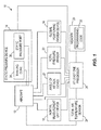
- Figure 1 illustrates a box diagram for one embodiment of a system 10 that may be used to determine the airspeed of an aircraft 12.
- the system 10 includes a static pressure device 14, a global positioning system device 16, an inertial measurement unit device 18, an angle of attack device 20, a total pressure sensor 22, a total air temperature sensor 24, at least one processor 26, and a memory 28.
- the static pressure device 14 is configured to determine a static pressure acting on the aircraft 12.
- the global positioning system device 16 is configured to determine an inertial position of the aircraft 12.
- the inertial measurement unit device 18 is configured to determine inertial measurements of the aircraft 12.
- the angle of attack device 20 is configured to determine an angle of attack of the aircraft 12.
- the total pressure sensor 22 is configured to determine a total pressure that the aircraft 12 experiences while the aircraft 12 is moving.
- the total air temperature sensor 24 is configured to determine a total air temperature that the aircraft 12 experiences while the aircraft 12 is moving.
- the at least one processor 26 is in electronic communication with the static pressure device 14, the global positioning system device 16, the inertial measurement unit device 18, the angle of attack device 20, the total pressure sensor 22, and the total air temperature sensor 24.
- the memory 28 is in electronic communication with the at least one processor 26.
- the memory 28 contains programming code 32 for execution by the at least one processor 26.
- the programming code 32 is configured to determine the airspeed of the aircraft 12 using data obtained from each of the static pressure device 14, the global positioning system device 16, the inertial measurement unit device 18, the angle of attack device 20, the total pressure sensor 22, and the total air temperature sensor 24.
- the static pressure device 14 comprises a trailing cone 34 or a static pressure port 36. In other embodiments, the static pressure device 14 may vary.
- the programming code 32 may be configured to determine a pressure altitude time history and a static pressure time history for the aircraft 12 using the data obtained from the static pressure device 14.
- the programming code 32 may be configured to determine a geometric altitude time history and a flight path angle time history for the aircraft 12 using the data obtained from the inertial measurement unit device 18 and the global positioning system device 16.
- the programming code 32 may be configured to determine a pressure altitude at a virtual trapped static point and a geometric altitude at a virtual trapped static point for the aircraft 12 using the data obtained from each of the static pressure device 14, the global positioning system device 16, the inertial measurement unit device 18, and the angle of attack device 20.
- the programming code 32 may be configured to determine a temperature deviation from a standard day and a temperature lapse rate deviation from a standard day using the data obtained from each of the static pressure device 14, the global positioning system device 16, the inertial measurement unit device 18, the total pressure sensor 22, and the total air temperature sensor 24.
- the programming code 32 may be configured to determine a calculated static pressure time history and a calculated pressure altitude time history for the aircraft 12 using the data obtained from each of the static pressure device 14, the global positioning system device 16, the inertial measurement unit device 18, the angle of attack device 20, the total pressure sensor 22, and the total air temperature sensor 24. In other embodiments, the programming code 32 may be configured to determine varying information.
- the airspeed of the aircraft 12 determined by the programming code 32 may comprise a calculated calibrated airspeed time history and a calculated Mach number time history for the aircraft 12. In other embodiments, the airspeed of the aircraft 12 determined by the programming code 32 may comprise varying information. In other embodiments, the system 10 of Figure 1 may vary.
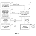
- Figure 2 illustrates a box diagram flowchart 40 for one embodiment of a method for determining an airspeed of an aircraft.
- an in-air virtual trapped static point determination determines the pressure altitude at a virtual trapped static point hp TRAP and the geometric altitude at a virtual trapped static point hz TRAP of the aircraft.
- the method shown in Figure 3 may be used to make the determination of box 42.
- a determination is made as to a temperature deviation from a standard day ⁇ T and a temperature lapse rate deviation from a standard day ⁇ L p for the ambient outside the aircraft.
- the method shown in Figure 6 may be used to make the determination of box 44.
- a global positioning system device and an inertial measurement unit device may be used to determine a geometric altitude time history hz(t) and a flight path angle time history ⁇ (t) for the aircraft. As discussed later in this disclosure, the method shown in Figure 5 may be used to make the determination of box 46.
- a total pressure sensor may be used to determine a total pressure time history pt(t) that the aircraft experiences while moving.
- the determinations of boxes 42, 44, and 46 may be used to determine a calculated static pressure time history ps CAL (t) and a calculated pressure altitude time history hp CAL (t) for the aircraft.
- the determinations of boxes 48 and 50 may be used to determine an airspeed calculation for the aircraft comprising a calculated calibrated airspeed time history VCAS CAL (t) and a calculated Mach number time history M CAL (t) for the aircraft.
- the method of Figure 2 may be varied.
- Figure 3 illustrates a box diagram flowchart 60 for one embodiment of a method for making the determination of box 42 of Figure 2 comprising the in-air virtual trapped static point determination for the aircraft.
- a determination is made using a static pressure system as to the pressure altitude time history hp(t) and the static pressure time history ps(t).
- the method shown in Figure 4 may be used to make the determination of box 62.
- a determination is made using a global positioning system device and an inertial measurement unit device as to a geometric altitude time history hz(t) and a flight path angle time history ⁇ (t) for the aircraft.
- the method shown in Figure 5 may be used to make the determination of box 64.
- the determinations of boxes 62, 64, and 66 may be used to determine the in-air virtual trapped static point determination comprising the pressure altitude at a virtual trapped static point hp TRAP and the geometric altitude at a virtual trapped static point hz TRAP for the aircraft.
- the method of Figure 3 may be varied.
- Figure 4 illustrates a box diagram flowchart 70 for one embodiment of a method for determining, using a static pressure system, the determination of box 62 of Figure 3 comprising a pressure altitude time history hp(t) and a static pressure time history ps(t) for the aircraft.
- a trailing cone is used to determine a raw static pressure for the aircraft.
- an acceleration and acoustic lag correction is applied to the determined raw static pressure to determine the pressure altitude time history hp(t) and the static pressure time history ps(t) for the aircraft.
- the steps of boxes 76 and 78 may be followed to determine the pressure altitude time history hp(t) and the static pressure time history ps(t) for the aircraft.
- a static pressure port is used to determine the raw static pressure for the aircraft.
- a static source error correction is applied to the determined raw static pressure to determine the pressure altitude time history hp(t) and the static pressure time history ps(t) for the aircraft.
- the method of Figure 4 may be varied.
- Figure 5 illustrates a box diagram flowchart 80 for one embodiment of a method for determining, using a global positioning system device and an inertial measurement unit device, the determination of box 46 of Figure 2 and the determination of box 64 of Figure 3 comprising a geometric altitude time history hz(t) and a flight path angle time history ⁇ (t) for the aircraft.
- an inertial measurement unit device is used to determine an inertial measurement unit ground speed time history Vg IMU (t), an inertial measurement unit drift angle time history ⁇ (t), inertial measurement unit Euler angles, and inertial measurement unit load factors for the aircraft.
- a summation is made summing the inertial measurement load factors determined by box 82 and load factor biases determined by a translational kinematic consistency algorithm of box 100 to determine corrected load factors.
- an Euler transformation is applied to the corrected load factors determined by box 84 using the inertial measurement unit Euler angles determined by box 82 to determine an aircraft north acceleration, an aircraft east acceleration, and an aircraft vertical acceleration.
- the determination of box 86 is integrated to determine a drift angle time history ⁇ (t), a ground speed time history V g (t), an aircraft vertical speed time history hzdot(t), and a flight path angle time history ⁇ (t).
- a summation is made summing the inertial measurement unit drift angle time history ⁇ IMU (t) determination of box 82, and the drift angle time history ⁇ (t) determination of box 88 to determine a drift angle error.
- a summation is made summing the inertial measurement ground speed time history Vg IMU (t) determination of box 82 and the ground speed time history Vg(t) determination of box 88 to determine a ground speed error.
- the aircraft vertical speed time history hzdot(t) is integrated to determine the geometric altitude time history hz(t).
- a global positioning system unit device is used to determine a WGS84 geometric altitude time history h GPS (t).
- a summation is made summing the WGS84 geometric altitude time history h GPS (t) determination of box 96 and the geometric altitude time history hz(t) determination of box 94 to determine a geometric altitude error.
- a translational kinematic consistency algorithm is applied to the geometric altitude error determination of box 98, to the drift angle error determination of box 90, and to the ground speed error determination of box 92 to determine the load factor biases.
- the method of Figure 5 may be varied.
- Figure 6 illustrates a box diagram flowchart 110 for one embodiment of a method for determining the determination of box 44 of Figure 2 comprising a temperature deviation from a standard day ⁇ T and a temperature lapse rate deviation from a standard day ⁇ Lp.
- the static pressure system of Figure 4 is used to determine a pressure altitude time history hp(t) and a static pressure time history ps(t).
- a total pressure sensor is used to determine a total pressure time history pt(t).
- a total air temperature sensor is used to determine a total air temperature time history T TOTAL (t).
- the global positioning system device and the inertial measurement unit device of Figure 5 is used to determine load factors and Euler angles.
- an airspeed system is used to determine a Mach number time history M(t) based on the static pressure time history ps(t) determination of box 112 and on the total pressure time history pt(t) determination of box 114.
- an actual ambient temperature calculation is made using the Mach number time history M(t) determination of box 120, a total air temperature TAT recovery factor f R , and the total temperature time history T TOTAL (T) determination of box 116 to determine the actual temperature time history T ACT (T).
- the pressure altitude time history hp(t) determination of box 112 is used to determine a standard day temperature calculation comprising a standard day temperature time history T STD (t).
- the load factors and Euler angles determined by box 118 are used along with an angle of attack time history ⁇ (t) and a side-slip angle time history ⁇ (t) to determine a tangential acceleration calculation comprising a tangential acceleration time history a ⁇ (t).
- the actual temperature time history T ACT (t) determination of box 122, the standard day temperature time history T STD (t) determination of box 124, and the tangential acceleration time history a ⁇ (t) determination of box 126 are used to determine the temperature deviation from a standard day ⁇ T and the temperature lapse rate deviation from a standard day ⁇ Lp.
- the method of Figure 6 may be varied.
- Figure 7 is a flowchart 130 illustrating one embodiment of a method for determining an airspeed of an aircraft.
- the airspeed of an aircraft may be determined with a processor based on each of a static pressure acting on the aircraft, an inertial position of the aircraft, an inertial measurement of the aircraft, an angle of attack of the aircraft, a total pressure that the aircraft experiences while the aircraft is moving, and a total air temperature that the aircraft experiences while the aircraft is moving.
- step 132 may comprise determining a calculated calibrated airspeed time history and a calculated Mach number time history for the aircraft.
- step 132 may further comprise making a determination as to the static pressure acting on the aircraft using a trailing cone or a static pressure port. In other embodiments, the determination as to the static pressure acting on the aircraft may be made using varying components.
- step 132 may further comprise making a determination as to a pressure altitude time history and as to a static pressure time history for the aircraft based on the static pressure acting on the aircraft.
- step 132 may further comprise making a determination as to the geometric altitude time history and as to a flight path angle time history for the aircraft based on the inertial measurement and on the inertial position of the aircraft.
- step 132 may further comprise making a determination as to a pressure altitude at a virtual trapped static point and as to a geometric altitude at a virtual trapped static point for the aircraft based on the static pressure, the inertial position, the inertial measurement, and the angle of attack of the aircraft.
- step 132 may further comprise making a determination as to a temperature deviation from a standard day and as to a temperature lapse rate deviation from a standard day based on each of the static pressure, the total pressure, the total air temperature, the inertial position, and the inertial measurement of the aircraft.
- step 132 may comprise making a determination as to a calculated static pressure time history and as to a calculated pressure altitude time history for the aircraft based on each of the static pressure, the inertial position, the inertial measurement, the angle of attack, the total pressure, and the total air temperature.
- any of the steps of the method of Figure 7 may not be followed, may be altered in substance or in order, or one or more additional steps may be followed in varying orders.
- Figure 8 illustrates a box diagram for one embodiment of a non-transitory computer readable medium 140 which includes instructions 142 to command a processor 144 to determine an airspeed of an aircraft 146.
- the instructions 142 may be configured to determine a calculated calibrated airspeed time history and a calculated Mach number time history for the aircraft 146.
- the instructions 142 may be configured to command the processor 144 to determine the airspeed of the aircraft 146 based on each of a static pressure acting on the aircraft 146, an inertial position of the aircraft 146, an inertial measurement of the aircraft 146, an angle of attack of the aircraft 146, a total pressure that the aircraft 146 experiences while the aircraft 146 is moving, and a total air temperature that the aircraft 146 experiences while the aircraft 146 is moving.
- the instructions 142 may further command the processor 144 to determine the static pressure acting on the aircraft 146 based on data from a trailing cone or a static pressure port. In another embodiment, the instructions 142 may further command the processor 144 to determine a pressure altitude time history and a static pressure time history for the aircraft 146 based on the raw static pressure measurements of the aircraft 146.
- the instructions 142 may further command the processor 144 to determine a geometric altitude time history and a flight path angle time history for the aircraft 146 based on the inertial measurement and the inertial position of the aircraft 146. In another embodiment, the instructions 142 may further command the processor 144 to determine a pressure altitude at a virtual trapped static point and a geometric altitude at a virtual trapped static point for the aircraft 146 based on the static pressure, the inertial position, the inertial measurement, and the angle of attack of the aircraft 146.
- the instructions 142 may further command the processor 144 to determine a temperature deviation from a standard day and a temperature lapse rate deviation from a standard day based on each of the static pressure, the total pressure, the total air temperature, the inertial position, and the inertial measurement of the aircraft 146.
- the instructions 142 may further command the processor 144 to determine a calculated static pressure time history and a calculated pressure altitude time history for the aircraft based on each of the static pressure, the inertial position, the inertial measurement, the angle of attack, the total pressure, and the total air temperature.
- the instructions 142 may be configured to command the processor 144 to take varying actions to determine varying information.
- One or more embodiments of the disclosure may reduce one or more issues associated with the current systems or methods for determining the airspeed of an aircraft. For instance, the use of trailing cones can be eliminated if desired which may reduce cost, and may increase reliability and accuracy. In other embodiments of the disclosure, one or more additional issues of one or more of the current systems or methods may be reduced or eliminated.
Landscapes
- Engineering & Computer Science (AREA)
- Physics & Mathematics (AREA)
- General Physics & Mathematics (AREA)
- Aviation & Aerospace Engineering (AREA)
- Radar, Positioning & Navigation (AREA)
- Remote Sensing (AREA)
- Automation & Control Theory (AREA)
- Navigation (AREA)
- Traffic Control Systems (AREA)
- Indicating Or Recording The Presence, Absence, Or Direction Of Movement (AREA)
Abstract
Description
- This disclosure relates to an airspeed calculation system for determining the airspeed of an aircraft.
- Current systems and methods for determining the airspeed of an aircraft typically use trailing cones to calibrate static pressure and airspeed. This is expensive and can experience reliability and accuracy issues.
- A system and method is needed to decrease or resolve one or more issues of one or more of the current systems or methods for determining the airspeed of an aircraft.
- In one embodiment, an airspeed calculation system is disclosed for determining the airspeed of an aircraft. The airspeed calculation system includes a static pressure device, a global positioning system device (GPS), an inertial measurement unit device (IMU), an angle of attack device, a total pressure sensor, a total air temperature sensor, at least one processor, and a memory. The static pressure device is configured to determine a static pressure acting on the aircraft. The global positioning system device is configured to determine an inertial position such as geometric altitude of the aircraft referenced to the 1984 World Geodetic System (WGS84). The inertial measurement unit device is configured to determine inertial measurements such as load factors, body angular rates and Euler angles of the aircraft. The angle of attack device is configured to determine an angle of attack of the aircraft. The total pressure sensor is configured to determine a total pressure that the aircraft experiences while the aircraft is moving. The total air temperature sensor is configured to determine a total air temperature that the aircraft experiences while the aircraft is moving. The at least one processor is in electronic communication with the static pressure device, the global positioning system device, the inertial measurement unit device, the angle of attack device, the total pressure sensor, and the total air temperature sensor. The memory is in electronic communication with the at least one processor. The memory includes programming code for execution by the at least one processor. The programming code is configured to determine an airspeed of the aircraft using data obtained from each of the static pressure device, the global positioning system device, the inertial measurement unit device, the angle of attack device, the total pressure sensor, and the total air temperature sensor.
- In another embodiment, a method for determining an airspeed of an aircraft is disclosed. A processor determines the airspeed of the aircraft based on each of a static pressure acting on the aircraft, an inertial position of the aircraft, an inertial measurement of the aircraft, an angle of attack of the aircraft, a total pressure that the aircraft experiences while the aircraft is moving, and a total air temperature that the aircraft experiences while the aircraft is moving.
- In still another embodiment, a non-transitory computer readable medium is disclosed. The non-transitory computer readable medium includes instructions to command a processor to determine an airspeed of an aircraft based on each of a static pressure acting on the aircraft, an inertial position of the aircraft, an inertial measurement of the aircraft, an angle of attack of the aircraft, a total pressure that the aircraft experiences while the aircraft is moving, and a total air temperature that the aircraft experiences while the aircraft is moving.
- The scope of the present disclosure is defined solely by the appended claims and is not affected by the statements within this summary.
- The disclosure can be better understood with reference to the following drawings and description. The components in the figures are not necessarily to scale, emphasis instead being placed upon illustrating the principles of the disclosure.
-
Figure 1 illustrates a box diagram for one embodiment of a system that may be used to determine the airspeed of an aircraft; -
Figure 2 illustrates a box diagram flowchart for one embodiment of a method for determining an airspeed of an aircraft; -
Figure 3 illustrates a box diagram flowchart for one embodiment of a method for making an in-air virtual trapped static point determination for an aircraft; -
Figure 4 illustrates a box diagram flowchart for one embodiment of a method for determining a pressure altitude time history hp(t) and a static pressure time history ps(t) for an aircraft; -
Figure 5 illustrates a box diagram flowchart for one embodiment of a method for determining a geometric altitude time history hz(t) and a flight path angle time history γ(t) for an aircraft; -
Figure 6 illustrates a box diagram flowchart for one embodiment of a method for determining a temperature deviation from a standard day ΔT and a temperature lapse rate deviation from a standard day ΔLp; -
Figure 7 is a flowchart illustrating one embodiment of a method for determining an airspeed of an aircraft; and -
Figure 8 illustrates a box diagram for one embodiment of a non-transitory computer readable medium which includes instructions to command a processor to determine an airspeed of an aircraft. -
Figure 1 illustrates a box diagram for one embodiment of asystem 10 that may be used to determine the airspeed of anaircraft 12. Thesystem 10 includes astatic pressure device 14, a globalpositioning system device 16, an inertialmeasurement unit device 18, an angle ofattack device 20, atotal pressure sensor 22, a totalair temperature sensor 24, at least oneprocessor 26, and amemory 28. - The
static pressure device 14 is configured to determine a static pressure acting on theaircraft 12. The globalpositioning system device 16 is configured to determine an inertial position of theaircraft 12. The inertialmeasurement unit device 18 is configured to determine inertial measurements of theaircraft 12. The angle ofattack device 20 is configured to determine an angle of attack of theaircraft 12. Thetotal pressure sensor 22 is configured to determine a total pressure that theaircraft 12 experiences while theaircraft 12 is moving. The totalair temperature sensor 24 is configured to determine a total air temperature that theaircraft 12 experiences while theaircraft 12 is moving. The at least oneprocessor 26 is in electronic communication with thestatic pressure device 14, the globalpositioning system device 16, the inertialmeasurement unit device 18, the angle ofattack device 20, thetotal pressure sensor 22, and the totalair temperature sensor 24. Thememory 28 is in electronic communication with the at least oneprocessor 26. Thememory 28 containsprogramming code 32 for execution by the at least oneprocessor 26. Theprogramming code 32 is configured to determine the airspeed of theaircraft 12 using data obtained from each of thestatic pressure device 14, the globalpositioning system device 16, the inertialmeasurement unit device 18, the angle ofattack device 20, thetotal pressure sensor 22, and the totalair temperature sensor 24. - In one embodiment, the
static pressure device 14 comprises atrailing cone 34 or astatic pressure port 36. In other embodiments, thestatic pressure device 14 may vary. Theprogramming code 32 may be configured to determine a pressure altitude time history and a static pressure time history for theaircraft 12 using the data obtained from thestatic pressure device 14. Theprogramming code 32 may be configured to determine a geometric altitude time history and a flight path angle time history for theaircraft 12 using the data obtained from the inertialmeasurement unit device 18 and the globalpositioning system device 16. Theprogramming code 32 may be configured to determine a pressure altitude at a virtual trapped static point and a geometric altitude at a virtual trapped static point for theaircraft 12 using the data obtained from each of thestatic pressure device 14, the globalpositioning system device 16, the inertialmeasurement unit device 18, and the angle ofattack device 20. Theprogramming code 32 may be configured to determine a temperature deviation from a standard day and a temperature lapse rate deviation from a standard day using the data obtained from each of thestatic pressure device 14, the globalpositioning system device 16, the inertialmeasurement unit device 18, thetotal pressure sensor 22, and the totalair temperature sensor 24. Theprogramming code 32 may be configured to determine a calculated static pressure time history and a calculated pressure altitude time history for theaircraft 12 using the data obtained from each of thestatic pressure device 14, the globalpositioning system device 16, the inertialmeasurement unit device 18, the angle ofattack device 20, thetotal pressure sensor 22, and the totalair temperature sensor 24. In other embodiments, theprogramming code 32 may be configured to determine varying information. The airspeed of theaircraft 12 determined by theprogramming code 32 may comprise a calculated calibrated airspeed time history and a calculated Mach number time history for theaircraft 12. In other embodiments, the airspeed of theaircraft 12 determined by theprogramming code 32 may comprise varying information. In other embodiments, thesystem 10 ofFigure 1 may vary. -
Figure 2 illustrates abox diagram flowchart 40 for one embodiment of a method for determining an airspeed of an aircraft. Inbox 42, an in-air virtual trapped static point determination determines the pressure altitude at a virtual trapped static point hpTRAP and the geometric altitude at a virtual trapped static point hzTRAP of the aircraft. As discussed later in this disclosure, the method shown inFigure 3 may be used to make the determination ofbox 42. Inbox 44, a determination is made as to a temperature deviation from a standard day ΔT and a temperature lapse rate deviation from a standard day ΔLp for the ambient outside the aircraft. As discussed later in this disclosure, the method shown inFigure 6 may be used to make the determination ofbox 44. Inbox 46, a global positioning system device and an inertial measurement unit device may be used to determine a geometric altitude time history hz(t) and a flight path angle time history γ(t) for the aircraft. As discussed later in this disclosure, the method shown inFigure 5 may be used to make the determination ofbox 46. Inbox 48, a total pressure sensor may be used to determine a total pressure time history pt(t) that the aircraft experiences while moving. Inbox 50, the determinations ofboxes box 52, the determinations ofboxes Figure 2 may be varied. -
Figure 3 illustrates abox diagram flowchart 60 for one embodiment of a method for making the determination ofbox 42 ofFigure 2 comprising the in-air virtual trapped static point determination for the aircraft. Inbox 62, a determination is made using a static pressure system as to the pressure altitude time history hp(t) and the static pressure time history ps(t). As discussed later in this disclosure, the method shown inFigure 4 may be used to make the determination ofbox 62. Inbox 64, a determination is made using a global positioning system device and an inertial measurement unit device as to a geometric altitude time history hz(t) and a flight path angle time history γ(t) for the aircraft. As discussed later in this disclosure, the method shown inFigure 5 may be used to make the determination ofbox 64. Inbox 66, a determination is made using an angle of attack system as to an angle of attack time history α(t) for the aircraft. Inbox 68, the determinations ofboxes Figure 3 may be varied. -
Figure 4 illustrates abox diagram flowchart 70 for one embodiment of a method for determining, using a static pressure system, the determination ofbox 62 ofFigure 3 comprising a pressure altitude time history hp(t) and a static pressure time history ps(t) for the aircraft. Inbox 72, a trailing cone is used to determine a raw static pressure for the aircraft. Inbox 74, an acceleration and acoustic lag correction is applied to the determined raw static pressure to determine the pressure altitude time history hp(t) and the static pressure time history ps(t) for the aircraft. Alternatively, instead of following the steps ofboxes boxes box 76, a static pressure port is used to determine the raw static pressure for the aircraft. Inbox 78, a static source error correction is applied to the determined raw static pressure to determine the pressure altitude time history hp(t) and the static pressure time history ps(t) for the aircraft. In other embodiments, the method ofFigure 4 may be varied. -
Figure 5 illustrates abox diagram flowchart 80 for one embodiment of a method for determining, using a global positioning system device and an inertial measurement unit device, the determination ofbox 46 ofFigure 2 and the determination ofbox 64 ofFigure 3 comprising a geometric altitude time history hz(t) and a flight path angle time history γ(t) for the aircraft. Inbox 82, an inertial measurement unit device is used to determine an inertial measurement unit ground speed time history VgIMU(t), an inertial measurement unit drift angle time history δ(t), inertial measurement unit Euler angles, and inertial measurement unit load factors for the aircraft. Inbox 84, a summation is made summing the inertial measurement load factors determined bybox 82 and load factor biases determined by a translational kinematic consistency algorithm ofbox 100 to determine corrected load factors. Inbox 86, an Euler transformation is applied to the corrected load factors determined bybox 84 using the inertial measurement unit Euler angles determined bybox 82 to determine an aircraft north acceleration, an aircraft east acceleration, and an aircraft vertical acceleration. Inbox 88, the determination ofbox 86 is integrated to determine a drift angle time history δ(t), a ground speed time history Vg(t), an aircraft vertical speed time history hzdot(t), and a flight path angle time history γ(t). Inbox 90, a summation is made summing the inertial measurement unit drift angle time history δIMU(t) determination ofbox 82, and the drift angle time history δ(t) determination ofbox 88 to determine a drift angle error. Inbox 92, a summation is made summing the inertial measurement ground speed time history VgIMU(t) determination ofbox 82 and the ground speed time history Vg(t) determination ofbox 88 to determine a ground speed error. Inbox 94, the aircraft vertical speed time history hzdot(t) is integrated to determine the geometric altitude time history hz(t). Inbox 96, a global positioning system unit device is used to determine a WGS84 geometric altitude time history hGPS(t). Inbox 98, a summation is made summing the WGS84 geometric altitude time history hGPS(t) determination ofbox 96 and the geometric altitude time history hz(t) determination ofbox 94 to determine a geometric altitude error. Inbox 100, a translational kinematic consistency algorithm is applied to the geometric altitude error determination ofbox 98, to the drift angle error determination ofbox 90, and to the ground speed error determination ofbox 92 to determine the load factor biases. In other embodiments, the method ofFigure 5 may be varied. -
Figure 6 illustrates abox diagram flowchart 110 for one embodiment of a method for determining the determination ofbox 44 ofFigure 2 comprising a temperature deviation from a standard day ΔT and a temperature lapse rate deviation from a standard day ΔLp. Inbox 112, the static pressure system ofFigure 4 is used to determine a pressure altitude time history hp(t) and a static pressure time history ps(t). - In
box 114, a total pressure sensor is used to determine a total pressure time history pt(t). Inbox 116, a total air temperature sensor is used to determine a total air temperature time history TTOTAL(t). Inbox 118, the global positioning system device and the inertial measurement unit device ofFigure 5 is used to determine load factors and Euler angles. Inbox 120, an airspeed system is used to determine a Mach number time history M(t) based on the static pressure time history ps(t) determination ofbox 112 and on the total pressure time history pt(t) determination ofbox 114. Inbox 122, an actual ambient temperature calculation is made using the Mach number time history M(t) determination ofbox 120, a total air temperature TAT recovery factor fR, and the total temperature time history TTOTAL(T) determination ofbox 116 to determine the actual temperature time history TACT(T). Inbox 124, the pressure altitude time history hp(t) determination ofbox 112 is used to determine a standard day temperature calculation comprising a standard day temperature time history TSTD(t). Inbox 126, the load factors and Euler angles determined bybox 118 are used along with an angle of attack time history α(t) and a side-slip angle time history β(t) to determine a tangential acceleration calculation comprising a tangential acceleration time history aτ(t). Inbox 128, the actual temperature time history TACT(t) determination ofbox 122, the standard day temperature time history TSTD(t) determination ofbox 124, and the tangential acceleration time history aτ(t) determination ofbox 126 are used to determine the temperature deviation from a standard day ΔT and the temperature lapse rate deviation from a standard day ΔLp. In other embodiments, the method ofFigure 6 may be varied. -
Figure 7 is aflowchart 130 illustrating one embodiment of a method for determining an airspeed of an aircraft. The systems and methods ofFigures 1-6 may be used to implement the method ofFigure 7 . Instep 132, the airspeed of an aircraft may be determined with a processor based on each of a static pressure acting on the aircraft, an inertial position of the aircraft, an inertial measurement of the aircraft, an angle of attack of the aircraft, a total pressure that the aircraft experiences while the aircraft is moving, and a total air temperature that the aircraft experiences while the aircraft is moving. In one embodiment, step 132 may comprise determining a calculated calibrated airspeed time history and a calculated Mach number time history for the aircraft. In another embodiment, step 132 may further comprise making a determination as to the static pressure acting on the aircraft using a trailing cone or a static pressure port. In other embodiments, the determination as to the static pressure acting on the aircraft may be made using varying components. - In another embodiment, step 132 may further comprise making a determination as to a pressure altitude time history and as to a static pressure time history for the aircraft based on the static pressure acting on the aircraft. In yet another embodiment, step 132 may further comprise making a determination as to the geometric altitude time history and as to a flight path angle time history for the aircraft based on the inertial measurement and on the inertial position of the aircraft. In an additional embodiment, step 132 may further comprise making a determination as to a pressure altitude at a virtual trapped static point and as to a geometric altitude at a virtual trapped static point for the aircraft based on the static pressure, the inertial position, the inertial measurement, and the angle of attack of the aircraft.
- In another embodiment, step 132 may further comprise making a determination as to a temperature deviation from a standard day and as to a temperature lapse rate deviation from a standard day based on each of the static pressure, the total pressure, the total air temperature, the inertial position, and the inertial measurement of the aircraft. In yet another embodiment, step 132 may comprise making a determination as to a calculated static pressure time history and as to a calculated pressure altitude time history for the aircraft based on each of the static pressure, the inertial position, the inertial measurement, the angle of attack, the total pressure, and the total air temperature. In other embodiments, any of the steps of the method of
Figure 7 may not be followed, may be altered in substance or in order, or one or more additional steps may be followed in varying orders. -
Figure 8 illustrates a box diagram for one embodiment of a non-transitory computerreadable medium 140 which includesinstructions 142 to command aprocessor 144 to determine an airspeed of anaircraft 146. In one embodiment, theinstructions 142 may be configured to determine a calculated calibrated airspeed time history and a calculated Mach number time history for theaircraft 146. Theinstructions 142 may be configured to command theprocessor 144 to determine the airspeed of theaircraft 146 based on each of a static pressure acting on theaircraft 146, an inertial position of theaircraft 146, an inertial measurement of theaircraft 146, an angle of attack of theaircraft 146, a total pressure that theaircraft 146 experiences while theaircraft 146 is moving, and a total air temperature that theaircraft 146 experiences while theaircraft 146 is moving. In one embodiment, theinstructions 142 may further command theprocessor 144 to determine the static pressure acting on theaircraft 146 based on data from a trailing cone or a static pressure port. In another embodiment, theinstructions 142 may further command theprocessor 144 to determine a pressure altitude time history and a static pressure time history for theaircraft 146 based on the raw static pressure measurements of theaircraft 146. - In still another embodiment, the
instructions 142 may further command theprocessor 144 to determine a geometric altitude time history and a flight path angle time history for theaircraft 146 based on the inertial measurement and the inertial position of theaircraft 146. In another embodiment, theinstructions 142 may further command theprocessor 144 to determine a pressure altitude at a virtual trapped static point and a geometric altitude at a virtual trapped static point for theaircraft 146 based on the static pressure, the inertial position, the inertial measurement, and the angle of attack of theaircraft 146. - In yet another embodiment, the
instructions 142 may further command theprocessor 144 to determine a temperature deviation from a standard day and a temperature lapse rate deviation from a standard day based on each of the static pressure, the total pressure, the total air temperature, the inertial position, and the inertial measurement of theaircraft 146. In an additional embodiment, theinstructions 142 may further command theprocessor 144 to determine a calculated static pressure time history and a calculated pressure altitude time history for the aircraft based on each of the static pressure, the inertial position, the inertial measurement, the angle of attack, the total pressure, and the total air temperature. In other embodiments, theinstructions 142 may be configured to command theprocessor 144 to take varying actions to determine varying information. - One or more embodiments of the disclosure may reduce one or more issues associated with the current systems or methods for determining the airspeed of an aircraft. For instance, the use of trailing cones can be eliminated if desired which may reduce cost, and may increase reliability and accuracy. In other embodiments of the disclosure, one or more additional issues of one or more of the current systems or methods may be reduced or eliminated.
- Further, the disclosure comprises embodiments according to the following clauses:
- Clause 1. An airspeed calculation system for determining the airspeed of an aircraft comprising:
- a static pressure device configured to determine a static pressure acting on the aircraft;
- a global positioning system device configured to determine an inertial position of the aircraft;
- an inertial measurement unit device configured to determine inertial measurements of the aircraft;
- an angle of attack device configured to determine an angle of attack of the aircraft;
- a total pressure sensor configured to determine a total pressure that the aircraft experiences while the aircraft is moving;
- a total air temperature sensor configured to determine a total air temperature that the aircraft experiences while the aircraft is moving;
- at least one processor in electronic communication with the static pressure device, the global positioning system device, the inertial measurement unit device, the angle of attack device, the total pressure sensor, and the total air temperature sensor; and
- a memory in electronic communication with the at least one processor, wherein the memory comprises programming code for execution by the at least one processor, and the programming code is configured to determine an airspeed of the aircraft using data obtained from each of the static pressure device, the global positioning system device, the inertial measurement unit device, the angle of attack device, the total pressure sensor, and the total air temperature sensor.
- Clause 2. The airspeed calculation system of clause 1 wherein the static pressure device comprises a trailing cone or a static pressure port.
- Clause 3. The airspeed calculation system of clause 1 wherein the programming code is configured to determine a pressure altitude time history and a static pressure time history for the aircraft using the data obtained from the static pressure device.
- Clause 4. The airspeed calculation system of clause 1 wherein the programming code is configured to determine a geometric altitude time history and a flight path angle time history for the aircraft using the data obtained from the inertial measurement unit device and the global positioning system device.
- Clause 5. The airspeed calculation system of clause 1 wherein the programming code is configured to determine a pressure altitude at a virtual trapped static point and a geometric altitude at a virtual trapped static point for the aircraft using the data obtained from each of the static pressure device, the global positioning system device, the inertial measurement unit device, and the angle of attack device.
- Clause 6. The airspeed calculation system of clause1 wherein the programming code is configured to determine a temperature deviation from a standard day and a temperature lapse rate deviation from a standard day using the data obtained from each of the static pressure device, the total pressure sensor, the total air temperature sensor, the global positioning system device, and the inertial measurement unit device.
- Clause 7. The airspeed calculation system of clause1 wherein the programming code is configured to determine a calculated static pressure time history and a calculated pressure altitude time history for the aircraft using the data obtained from each of the static pressure device, the global positioning system device, the inertial measurement unit device, the angle of attack device, the total pressure sensor, and the total air temperature sensor.
- Clause 8.The airspeed calculation system of clause1 wherein the airspeed of the aircraft determined by the programming code comprises a calculated calibrated airspeed time history and a calculated Mach number time history for the aircraft.
- Clause 9. A method for determining an airspeed of an aircraft comprising:
- determining with a processor the airspeed of the aircraft based on each of a static pressure acting on the aircraft, an inertial position of the aircraft, an inertial measurement of the aircraft, an angle of attack of the aircraft, a total pressure that the aircraft experiences while the aircraft is moving, and a total air temperature that the aircraft experiences while the aircraft is moving.
-
Clause 10. The method of clause 9 further comprising determining the static pressure acting on the aircraft using a trailing cone or a static pressure port. - Clause 11. The method of clause 9 further comprising determining a pressure altitude time history and a static pressure time history for the aircraft based on raw static pressure measurements of the aircraft.
-
Clause 12. The method of clause 9 further comprising determining a geometric altitude time history and a flight path angle time history for the aircraft based on the inertial measurement and the inertial position of the aircraft. - Clause 13. The method of clause 9 further comprising determining a pressure altitude at a virtual trapped static point and a geometric altitude at a virtual trapped static point for the aircraft based on the static pressure, the inertial position, the inertial measurement, and the angle of attack of the aircraft.
-
Clause 14. The method of clause 9 further comprising determining a temperature deviation from a standard day and a temperature lapse rate deviation from a standard day based on each of the static pressure, the total pressure, the total air temperature, the inertial position, and the inertial measurement of the aircraft. - Clause 15. The method of clause 9 further comprising determining a calculated static pressure time history and a calculated pressure altitude time history for the aircraft based on each of the static pressure, the inertial position, the inertial measurement, the angle of attack, the total pressure, and the total air temperature.
-
Clause 16. The method of clause 9 wherein the determining with the processor the airspeed of the aircraft comprises determining a calculated calibrated airspeed time history and a calculated Mach number time history for the aircraft. - Clause 17. A non-transitory computer readable medium including instructions to command a processor to:
- determine an airspeed of an aircraft based on each of a static pressure acting on the aircraft, an inertial position of the aircraft, an inertial measurement of the aircraft, an angle of attack of the aircraft, a total pressure that the aircraft experiences while the aircraft is moving, and a total air temperature that the aircraft experiences while the aircraft is moving.
-
Clause 18. The non-transitory computer readable medium of clause 17 wherein the instructions further command the processor to determine the static pressure acting on the aircraft based on data from a trailing cone or a static pressure port. - Clause 19. The non-transitory computer readable medium of clause 17 wherein the instructions further command the processor to determine a pressure altitude time history and a static pressure time history for the aircraft based on raw static pressure measurements of the aircraft.
-
Clause 20. The non-transitory computer readable medium of clause 17 wherein the instructions further command the processor to determine a geometric altitude time history and a flight path angle time history for the aircraft based on the inertial measurement and the inertial position of the aircraft. - Clause 21. The non-transitory computer readable medium of clause17 wherein the instructions further command the processor to determine a pressure altitude at a virtual trapped static point and a geometric altitude at a virtual trapped static point for the aircraft based on the static pressure, the inertial position, the inertial measurement, and the angle of attack of the aircraft.
-
Clause 22. The non-transitory computer readable medium of clause 17 wherein the instructions further command the processor to determine a temperature deviation from a standard day and a temperature lapse rate deviation from a standard day based on each of the static pressure, the total pressure, the total air temperature, the inertial position, and the inertial measurement of the aircraft. - Clause 23. The non-transitory computer readable medium of clause 17 wherein the instructions further command the processor to determine a calculated static pressure time history and a calculated pressure altitude time history for the aircraft based on each of the static pressure, the inertial position, the inertial measurement, the angle of attack, the total pressure, and the total air temperature.
-
Clause 24. The non-transitory computer readable medium of clause17 wherein the instructions further command the processor to determine a calculated calibrated airspeed time history and a calculated Mach number time history for the aircraft. - The Abstract is provided to allow the reader to quickly ascertain the nature of the technical disclosure. It is submitted with the understanding that it will not be used to interpret or limit the scope or meaning of the claims. In addition, in the foregoing Detailed Description, it can be seen that various features are grouped together in various embodiments for the purpose of streamlining the disclosure. This method of disclosure is not to be interpreted as reflecting an intention that the claimed embodiments require more features than are expressly recited in each claim. Rather, as the following claims reflect, inventive subject matter lies in less than all features of a single disclosed embodiment. Thus the following claims are hereby incorporated into the Detailed Description, with each claim standing on its own as a separately claimed subject matter.
- While particular aspects of the present subject matter described herein have been shown and described, it will be apparent to those skilled in the art that, based upon the teachings herein, changes and modifications may be made without departing from the subject matter described herein and its broader aspects and, therefore, the appended claims are to encompass within their scope all such changes and modifications as are within the true scope of the subject matter described herein. Furthermore, it is to be understood that the disclosure is defined by the appended claims. Accordingly, the disclosure is not to be restricted except in light of the appended claims and their equivalents.
Claims (15)
- An airspeed calculation system for determining the airspeed of an aircraft (10) comprising:a static pressure device (14) configured to determine a static pressure acting on the aircraft;a global positioning system device (16) configured to determine an inertial position of the aircraft;an inertial measurement unit device (18) configured to determine inertial measurements of the aircraft;an angle of attack device (20) configured to determine an angle of attack of the aircraft;a total pressure sensor (22) configured to determine a total pressure that the aircraft experiences while the aircraft is moving;a total air temperature sensor (24) configured to determine a total air temperature that the aircraft experiences while the aircraft is moving;at least one processor (26) in electronic communication with the static pressure device (14), the global positioning system device (16), the inertial measurement unit device (18), the angle of attack device (20), the total pressure sensor (22), and the total air temperature sensor (24); anda memory (28) in electronic communication with the at least one processor (26), wherein the memory comprises programming code (32) for execution by the at least one processor (26), and the programming code (32) is configured to determine an airspeed of the aircraft using data obtained from each of the static pressure device (14), the global positioning system device (16), the inertial measurement unit device (18), the angle of attack device (20), the total pressure sensor (22), and the total air temperature sensor (24).
- The airspeed calculation system of claim 1 wherein the static pressure device (14) comprises a trailing cone (34) or a static pressure port (36).
- The airspeed calculation system of claim 1 wherein the programming code (32) is configured to determine a pressure altitude time history and a static pressure time history (50) for the aircraft using the data obtained from the static pressure device (14).
- The airspeed calculation system of claim 1 wherein the programming code (32) is configured to determine a geometric altitude time history and a flight path angle time history for the aircraft using the data obtained from the inertial measurement unit device and the global positioning system device (64).
- The airspeed calculation system of claim 1 wherein the programming code (32) is configured to determine a pressure altitude at a virtual trapped static point (42) and a geometric altitude (46) at a virtual trapped static point (42) for the aircraft using the data obtained from each of the static pressure device (62), the global positioning system device (16), the inertial measurement unit device (18), and the angle of attack device (20).
- The airspeed calculation system of claim 1 wherein the programming code (32) is configured to determine a temperature deviation from a standard day and a temperature lapse rate deviation from a standard day (44) using the data obtained from each of the static pressure device (14), the total pressure sensor (22), the total air temperature sensor (24), the global positioning system device (16), and the inertial measurement unit device (18).
- The airspeed calculation system of claim 1 wherein the programming code (32) is configured to determine a calculated static pressure time history and a calculated pressure altitude time history (50) for the aircraft using the data obtained from each of the static pressure device (14), the global positioning system device (16), the inertial measurement unit device (18), the angle of attack device (20), the total pressure sensor (22), and the total air temperature sensor (24).
- The airspeed calculation system of claim 1 wherein the airspeed of the aircraft determined by the programming code (32) comprises a calculated calibrated airspeed time history and a calculated Mach number time history (52) for the aircraft.
- A method for determining an airspeed of an aircraft comprising:determining with a processor the airspeed of the aircraft based on each of a static pressure acting on the aircraft, an inertial position of the aircraft, an inertial measurement of the aircraft, an angle of attack of the aircraft, a total pressure that the aircraft experiences while the aircraft is moving, and a total air temperature (132) that the aircraft experiences while the aircraft is moving.
- The method of claim 9 further comprising determining the static pressure acting on the aircraft using a trailing cone (72) or a static pressure port (76).
- The method of claim 9 further comprising determining a pressure altitude time history and a static pressure time history for the aircraft based on raw static pressure measurements of the aircraft (70).
- The method of claim 9 further comprising determining a geometric altitude time history and a flight path angle time history for the aircraft based on the inertial measurement and the inertial position (64) of the aircraft.
- The method of claim 9 further comprising determining a pressure altitude at a virtual trapped static point and a geometric altitude at a virtual trapped static point (42) for the aircraft based on the static pressure (14), the inertial position (18), the inertial measurement (18), and the angle of attack of the aircraft.
- The method of claim 9 further comprising determining a temperature deviation from a standard day and a temperature lapse rate deviation from a standard day (44) based on each of the static pressure (14), the total pressure (22), the total air temperature (24), the inertial position, and the inertial measurement (18) of the aircraft.
- The method of claim 9 further comprising determining a calculated static pressure time history and a calculated pressure altitude time history (50) for the aircraft based on each of the static pressure (14), the inertial position, the inertial measurement (18), the angle of attack (20), the total pressure (22), and the total air temperature (24).
Applications Claiming Priority (1)
| Application Number | Priority Date | Filing Date | Title |
|---|---|---|---|
| US14/209,661 US9383381B2 (en) | 2014-03-13 | 2014-03-13 | Airspeed calculation system for an aircraft |
Publications (2)
| Publication Number | Publication Date |
|---|---|
| EP2919018A1 true EP2919018A1 (en) | 2015-09-16 |
| EP2919018B1 EP2919018B1 (en) | 2018-03-07 |
Family
ID=52144417
Family Applications (1)
| Application Number | Title | Priority Date | Filing Date |
|---|---|---|---|
| EP14198277.7A Active EP2919018B1 (en) | 2014-03-13 | 2014-12-16 | Airspeed calculation system for an aircraft |
Country Status (6)
| Country | Link |
|---|---|
| US (1) | US9383381B2 (en) |
| EP (1) | EP2919018B1 (en) |
| JP (1) | JP6580325B2 (en) |
| CN (1) | CN104914271B (en) |
| BR (1) | BR102015003266B1 (en) |
| CA (1) | CA2875708C (en) |
Cited By (2)
| Publication number | Priority date | Publication date | Assignee | Title |
|---|---|---|---|---|
| EP3425363A1 (en) * | 2017-07-03 | 2019-01-09 | The Boeing Company | Systems and methods for correcting acoustic error in pressure sensors |
| EP3508815A1 (en) * | 2018-01-05 | 2019-07-10 | The Boeing Company | Methods and systems for determining airspeed of an aircraft |
Families Citing this family (12)
| Publication number | Priority date | Publication date | Assignee | Title |
|---|---|---|---|---|
| FR2988851B1 (en) * | 2012-03-28 | 2014-04-25 | Dassault Aviat | METHOD FOR DETERMINING A CREDIBILITY STATE OF MEASUREMENTS OF AN AIRCRAFT INCIDENT SENSOR AND CORRESPONDING SYSTEM |
| KR101404430B1 (en) * | 2013-06-11 | 2014-06-10 | 서울시립대학교 산학협력단 | Method for estimation of surface temperature lapse rate Using thermal infrared images |
| FR3029638B1 (en) * | 2014-12-05 | 2018-03-02 | Airbus Operations | METHOD AND DEVICE FOR ESTIMATING AERODYNAMIC SPEED OF AN AIRCRAFT |
| EP3619499B1 (en) * | 2017-05-02 | 2024-07-10 | Airbus Canada Managing GP Inc. | Temperature correction of vertical speed of aircraft |
| US10605822B2 (en) * | 2017-06-12 | 2020-03-31 | The Boeing Company | System for estimating airspeed of an aircraft based on a weather buffer model |
| WO2019099545A1 (en) | 2017-11-14 | 2019-05-23 | Gulfstream Aerospace Corporation | Potential aircraft trajectory wind effect computation |
| WO2019099534A1 (en) * | 2017-11-14 | 2019-05-23 | Gulfstream Aerospace Corporation | Conversion between calibrated airspeed and true airspeed in trajectory modeling |
| US20230075640A1 (en) * | 2021-09-07 | 2023-03-09 | Nextnav, Llc | Determination of Altitude Uncertainty Including Temperature Lapse Rate |
| CN113533784B (en) * | 2021-09-07 | 2022-01-25 | 成都飞机工业(集团)有限责任公司 | GPS (global positioning system) round-trip non-constant-speed flat flight airspeed calibration method |
| CN114371313B (en) * | 2021-12-08 | 2023-12-01 | 中国航空工业集团公司北京长城计量测试技术研究所 | Neural network-based dragline system time delay compensation method |
| CN119239966B (en) * | 2024-10-15 | 2025-10-24 | 中国直升机设计研究所 | A method for correcting helicopter indicated airspeed by aerodynamic angle of attack |
| CN119916833B (en) * | 2024-12-27 | 2026-01-06 | 太原航空仪表有限公司 | A method for total static pressure compensation correction based on helicopter flight status |
Citations (6)
| Publication number | Priority date | Publication date | Assignee | Title |
|---|---|---|---|---|
| US5349347A (en) * | 1993-03-29 | 1994-09-20 | Alliedsignal Inc. | Method and apparatus for correcting dynamically induced errors in static pressure, airspeed and airspeed rate |
| US7389164B1 (en) * | 2007-01-22 | 2008-06-17 | Honeywell International, Inc. | Systems and methods for automatic detection of QFE operations |
| US20110238373A1 (en) * | 2009-12-14 | 2011-09-29 | United States of America as represented by the Administrator of the National Aeronautics and | In-Flight Pitot-Static Calibration |
| US20110264308A1 (en) * | 2010-04-21 | 2011-10-27 | Airbus Operations (S.A.S.) | Method And Device For Automatically Estimating An Air Speed Of An Aircraft |
| EP2434296A2 (en) * | 2010-09-27 | 2012-03-28 | The Boeing Company | Airspeed sensing system for an aircraft |
| FR2988835A1 (en) * | 2012-03-28 | 2013-10-04 | Dassault Aviat | METHOD FOR DETERMINING A CREDIBILITY STATE OF SENSOR MEASUREMENTS OF AN AIRCRAFT AND CORRESPONDING SYSTEM |
Family Cites Families (12)
| Publication number | Priority date | Publication date | Assignee | Title |
|---|---|---|---|---|
| JPS5432590B2 (en) * | 1974-06-05 | 1979-10-15 | ||
| JP2952397B2 (en) * | 1994-08-23 | 1999-09-27 | 科学技術庁航空宇宙技術研究所長 | Active air control aircraft using air speed vector measurement device |
| FR2784457B1 (en) * | 1998-10-13 | 2001-01-05 | Sextant Avionique | COMBINED EMERGENCY INSTRUMENTS FOR AIRCRAFT |
| US6668640B1 (en) | 2002-08-12 | 2003-12-30 | Rosemount Aerospace Inc. | Dual-channel electronic multi-function probes and methods for realizing dissimilar and independent air data outputs |
| US6757624B1 (en) * | 2002-12-03 | 2004-06-29 | Rockwell Collins | Synthetic pressure altitude determining system and method of integrity monitoring from a pressure sensor |
| US7299113B2 (en) * | 2004-01-15 | 2007-11-20 | The Boeing Company | System and method for determining aircraft tapeline altitude |
| FR2891368B1 (en) | 2005-09-27 | 2007-11-30 | Airbus France Sas | SYSTEM FOR MONITORING ANEMOBAROMLINOMETRIC PARAMETERS FOR AIRCRAFT |
| US8761970B2 (en) * | 2008-10-21 | 2014-06-24 | The Boeing Company | Alternative method to determine the air mass state of an aircraft and to validate and augment the primary method |
| FR2941314B1 (en) | 2009-01-20 | 2011-03-04 | Airbus France | METHOD FOR CONTROLLING AN AIRCRAFT USING A VOTING SYSTEM |
| CN102050226A (en) * | 2009-10-30 | 2011-05-11 | 航天科工惯性技术有限公司 | Aviation emergency instrument, and system initial alignment method and combined navigation algorithm thereof |
| DE102010018547A1 (en) * | 2010-04-28 | 2011-11-03 | Airbus Operations Gmbh | Apparatus and method for measuring air pressure and system for acquiring air data |
| CN102879793B (en) * | 2012-09-28 | 2014-07-23 | 北京信息科技大学 | Super-miniature GPS (global positioning system), INS (inertial navigation system), magnetometer and barometer integrated navigation system |
-
2014
- 2014-03-13 US US14/209,661 patent/US9383381B2/en active Active
- 2014-12-16 EP EP14198277.7A patent/EP2919018B1/en active Active
- 2014-12-18 JP JP2014255951A patent/JP6580325B2/en active Active
- 2014-12-22 CA CA2875708A patent/CA2875708C/en active Active
-
2015
- 2015-01-30 CN CN201510050426.2A patent/CN104914271B/en active Active
- 2015-02-12 BR BR102015003266-8A patent/BR102015003266B1/en not_active IP Right Cessation
Patent Citations (6)
| Publication number | Priority date | Publication date | Assignee | Title |
|---|---|---|---|---|
| US5349347A (en) * | 1993-03-29 | 1994-09-20 | Alliedsignal Inc. | Method and apparatus for correcting dynamically induced errors in static pressure, airspeed and airspeed rate |
| US7389164B1 (en) * | 2007-01-22 | 2008-06-17 | Honeywell International, Inc. | Systems and methods for automatic detection of QFE operations |
| US20110238373A1 (en) * | 2009-12-14 | 2011-09-29 | United States of America as represented by the Administrator of the National Aeronautics and | In-Flight Pitot-Static Calibration |
| US20110264308A1 (en) * | 2010-04-21 | 2011-10-27 | Airbus Operations (S.A.S.) | Method And Device For Automatically Estimating An Air Speed Of An Aircraft |
| EP2434296A2 (en) * | 2010-09-27 | 2012-03-28 | The Boeing Company | Airspeed sensing system for an aircraft |
| FR2988835A1 (en) * | 2012-03-28 | 2013-10-04 | Dassault Aviat | METHOD FOR DETERMINING A CREDIBILITY STATE OF SENSOR MEASUREMENTS OF AN AIRCRAFT AND CORRESPONDING SYSTEM |
Cited By (6)
| Publication number | Priority date | Publication date | Assignee | Title |
|---|---|---|---|---|
| EP3425363A1 (en) * | 2017-07-03 | 2019-01-09 | The Boeing Company | Systems and methods for correcting acoustic error in pressure sensors |
| US10323997B2 (en) | 2017-07-03 | 2019-06-18 | The Boeing Company | Systems and methods for correcting acoustic error in pressure sensors |
| US11085845B2 (en) | 2017-07-03 | 2021-08-10 | The Boeing Company | Systems and methods for correcting acoustic error in pressure sensors |
| EP3508815A1 (en) * | 2018-01-05 | 2019-07-10 | The Boeing Company | Methods and systems for determining airspeed of an aircraft |
| US20190210740A1 (en) * | 2018-01-05 | 2019-07-11 | The Boeing Company | Methods and systems for determining airspeed of an aircraft |
| US10822109B2 (en) | 2018-01-05 | 2020-11-03 | The Boeing Company | Methods and systems for determining airspeed of an aircraft |
Also Published As
| Publication number | Publication date |
|---|---|
| US9383381B2 (en) | 2016-07-05 |
| JP2015175847A (en) | 2015-10-05 |
| CN104914271B (en) | 2020-01-14 |
| CN104914271A (en) | 2015-09-16 |
| JP6580325B2 (en) | 2019-09-25 |
| US20150260749A1 (en) | 2015-09-17 |
| BR102015003266B1 (en) | 2021-05-04 |
| CA2875708A1 (en) | 2015-09-13 |
| CA2875708C (en) | 2018-09-25 |
| EP2919018B1 (en) | 2018-03-07 |
| BR102015003266A2 (en) | 2017-09-19 |
Similar Documents
| Publication | Publication Date | Title |
|---|---|---|
| US9383381B2 (en) | Airspeed calculation system for an aircraft | |
| CN104346522B (en) | System and method for calculating Mach number and true air speed | |
| CN110007109B (en) | Aircraft and method and system for determining airspeed of aircraft | |
| US9096330B2 (en) | System and method for computing MACH number and true airspeed | |
| JP6016550B2 (en) | Aircraft speed guidance display | |
| JP2015526726A (en) | Wind vector estimation | |
| US8457882B2 (en) | Systems and methods for navigation in a GPS-denied environment | |
| US20180156633A1 (en) | System and method for vertical flight display | |
| EP3143468B1 (en) | Advanced aircraft vision system utilizing multi-sensor gain scheduling | |
| EP3022565B1 (en) | System and process for measuring and evaluating air and inertial data | |
| CN111344645B (en) | Conversion between calibrated airspeed and true airspeed in trajectory modeling | |
| US7347090B1 (en) | Methods and systems for calculating atmospheric vehicle air data | |
| US20080278367A1 (en) | Integrated attitude altimeter | |
| CN106527482A (en) | Unmanned aerial vehicle flight control method and device | |
| CN110546457B (en) | Temperature correction of aircraft vertical speed | |
| CN118111497A (en) | Microburst identification method, device, equipment and storage medium | |
| EP2650650A1 (en) | Method and Apparatus for processing of GPS Heading Data for use by Electronic Flight Director |
Legal Events
| Date | Code | Title | Description |
|---|---|---|---|
| PUAI | Public reference made under article 153(3) epc to a published international application that has entered the european phase |
Free format text: ORIGINAL CODE: 0009012 |
|
| AK | Designated contracting states |
Kind code of ref document: A1 Designated state(s): AL AT BE BG CH CY CZ DE DK EE ES FI FR GB GR HR HU IE IS IT LI LT LU LV MC MK MT NL NO PL PT RO RS SE SI SK SM TR |
|
| AX | Request for extension of the european patent |
Extension state: BA ME |
|
| 17P | Request for examination filed |
Effective date: 20160315 |
|
| RBV | Designated contracting states (corrected) |
Designated state(s): AL AT BE BG CH CY CZ DE DK EE ES FI FR GB GR HR HU IE IS IT LI LT LU LV MC MK MT NL NO PL PT RO RS SE SI SK SM TR |
|
| 17Q | First examination report despatched |
Effective date: 20160718 |
|
| STAA | Information on the status of an ep patent application or granted ep patent |
Free format text: STATUS: EXAMINATION IS IN PROGRESS |
|
| GRAP | Despatch of communication of intention to grant a patent |
Free format text: ORIGINAL CODE: EPIDOSNIGR1 |
|
| STAA | Information on the status of an ep patent application or granted ep patent |
Free format text: STATUS: GRANT OF PATENT IS INTENDED |
|
| INTG | Intention to grant announced |
Effective date: 20171204 |
|
| GRAS | Grant fee paid |
Free format text: ORIGINAL CODE: EPIDOSNIGR3 |
|
| GRAA | (expected) grant |
Free format text: ORIGINAL CODE: 0009210 |
|
| STAA | Information on the status of an ep patent application or granted ep patent |
Free format text: STATUS: THE PATENT HAS BEEN GRANTED |
|
| AK | Designated contracting states |
Kind code of ref document: B1 Designated state(s): AL AT BE BG CH CY CZ DE DK EE ES FI FR GB GR HR HU IE IS IT LI LT LU LV MC MK MT NL NO PL PT RO RS SE SI SK SM TR |
|
| REG | Reference to a national code |
Ref country code: GB Ref legal event code: FG4D |
|
| REG | Reference to a national code |
Ref country code: CH Ref legal event code: EP Ref country code: AT Ref legal event code: REF Ref document number: 977132 Country of ref document: AT Kind code of ref document: T Effective date: 20180315 |
|
| REG | Reference to a national code |
Ref country code: IE Ref legal event code: FG4D |
|
| REG | Reference to a national code |
Ref country code: DE Ref legal event code: R096 Ref document number: 602014021932 Country of ref document: DE |
|
| REG | Reference to a national code |
Ref country code: NL Ref legal event code: MP Effective date: 20180307 |
|
| REG | Reference to a national code |
Ref country code: LT Ref legal event code: MG4D |
|
| PG25 | Lapsed in a contracting state [announced via postgrant information from national office to epo] |
Ref country code: HR Free format text: LAPSE BECAUSE OF FAILURE TO SUBMIT A TRANSLATION OF THE DESCRIPTION OR TO PAY THE FEE WITHIN THE PRESCRIBED TIME-LIMIT Effective date: 20180307 Ref country code: CY Free format text: LAPSE BECAUSE OF FAILURE TO SUBMIT A TRANSLATION OF THE DESCRIPTION OR TO PAY THE FEE WITHIN THE PRESCRIBED TIME-LIMIT Effective date: 20180307 Ref country code: ES Free format text: LAPSE BECAUSE OF FAILURE TO SUBMIT A TRANSLATION OF THE DESCRIPTION OR TO PAY THE FEE WITHIN THE PRESCRIBED TIME-LIMIT Effective date: 20180307 Ref country code: LT Free format text: LAPSE BECAUSE OF FAILURE TO SUBMIT A TRANSLATION OF THE DESCRIPTION OR TO PAY THE FEE WITHIN THE PRESCRIBED TIME-LIMIT Effective date: 20180307 Ref country code: NO Free format text: LAPSE BECAUSE OF FAILURE TO SUBMIT A TRANSLATION OF THE DESCRIPTION OR TO PAY THE FEE WITHIN THE PRESCRIBED TIME-LIMIT Effective date: 20180607 Ref country code: FI Free format text: LAPSE BECAUSE OF FAILURE TO SUBMIT A TRANSLATION OF THE DESCRIPTION OR TO PAY THE FEE WITHIN THE PRESCRIBED TIME-LIMIT Effective date: 20180307 |
|
| REG | Reference to a national code |
Ref country code: AT Ref legal event code: MK05 Ref document number: 977132 Country of ref document: AT Kind code of ref document: T Effective date: 20180307 |
|
| PG25 | Lapsed in a contracting state [announced via postgrant information from national office to epo] |
Ref country code: LV Free format text: LAPSE BECAUSE OF FAILURE TO SUBMIT A TRANSLATION OF THE DESCRIPTION OR TO PAY THE FEE WITHIN THE PRESCRIBED TIME-LIMIT Effective date: 20180307 Ref country code: SE Free format text: LAPSE BECAUSE OF FAILURE TO SUBMIT A TRANSLATION OF THE DESCRIPTION OR TO PAY THE FEE WITHIN THE PRESCRIBED TIME-LIMIT Effective date: 20180307 Ref country code: BG Free format text: LAPSE BECAUSE OF FAILURE TO SUBMIT A TRANSLATION OF THE DESCRIPTION OR TO PAY THE FEE WITHIN THE PRESCRIBED TIME-LIMIT Effective date: 20180607 Ref country code: GR Free format text: LAPSE BECAUSE OF FAILURE TO SUBMIT A TRANSLATION OF THE DESCRIPTION OR TO PAY THE FEE WITHIN THE PRESCRIBED TIME-LIMIT Effective date: 20180608 Ref country code: RS Free format text: LAPSE BECAUSE OF FAILURE TO SUBMIT A TRANSLATION OF THE DESCRIPTION OR TO PAY THE FEE WITHIN THE PRESCRIBED TIME-LIMIT Effective date: 20180307 |
|
| PG25 | Lapsed in a contracting state [announced via postgrant information from national office to epo] |
Ref country code: AL Free format text: LAPSE BECAUSE OF FAILURE TO SUBMIT A TRANSLATION OF THE DESCRIPTION OR TO PAY THE FEE WITHIN THE PRESCRIBED TIME-LIMIT Effective date: 20180307 Ref country code: PL Free format text: LAPSE BECAUSE OF FAILURE TO SUBMIT A TRANSLATION OF THE DESCRIPTION OR TO PAY THE FEE WITHIN THE PRESCRIBED TIME-LIMIT Effective date: 20180307 Ref country code: EE Free format text: LAPSE BECAUSE OF FAILURE TO SUBMIT A TRANSLATION OF THE DESCRIPTION OR TO PAY THE FEE WITHIN THE PRESCRIBED TIME-LIMIT Effective date: 20180307 Ref country code: NL Free format text: LAPSE BECAUSE OF FAILURE TO SUBMIT A TRANSLATION OF THE DESCRIPTION OR TO PAY THE FEE WITHIN THE PRESCRIBED TIME-LIMIT Effective date: 20180307 Ref country code: IT Free format text: LAPSE BECAUSE OF FAILURE TO SUBMIT A TRANSLATION OF THE DESCRIPTION OR TO PAY THE FEE WITHIN THE PRESCRIBED TIME-LIMIT Effective date: 20180307 Ref country code: RO Free format text: LAPSE BECAUSE OF FAILURE TO SUBMIT A TRANSLATION OF THE DESCRIPTION OR TO PAY THE FEE WITHIN THE PRESCRIBED TIME-LIMIT Effective date: 20180307 |
|
| PG25 | Lapsed in a contracting state [announced via postgrant information from national office to epo] |
Ref country code: SM Free format text: LAPSE BECAUSE OF FAILURE TO SUBMIT A TRANSLATION OF THE DESCRIPTION OR TO PAY THE FEE WITHIN THE PRESCRIBED TIME-LIMIT Effective date: 20180307 Ref country code: AT Free format text: LAPSE BECAUSE OF FAILURE TO SUBMIT A TRANSLATION OF THE DESCRIPTION OR TO PAY THE FEE WITHIN THE PRESCRIBED TIME-LIMIT Effective date: 20180307 Ref country code: CZ Free format text: LAPSE BECAUSE OF FAILURE TO SUBMIT A TRANSLATION OF THE DESCRIPTION OR TO PAY THE FEE WITHIN THE PRESCRIBED TIME-LIMIT Effective date: 20180307 Ref country code: SK Free format text: LAPSE BECAUSE OF FAILURE TO SUBMIT A TRANSLATION OF THE DESCRIPTION OR TO PAY THE FEE WITHIN THE PRESCRIBED TIME-LIMIT Effective date: 20180307 |
|
| REG | Reference to a national code |
Ref country code: DE Ref legal event code: R097 Ref document number: 602014021932 Country of ref document: DE |
|
| PG25 | Lapsed in a contracting state [announced via postgrant information from national office to epo] |
Ref country code: PT Free format text: LAPSE BECAUSE OF FAILURE TO SUBMIT A TRANSLATION OF THE DESCRIPTION OR TO PAY THE FEE WITHIN THE PRESCRIBED TIME-LIMIT Effective date: 20180709 |
|
| PLBE | No opposition filed within time limit |
Free format text: ORIGINAL CODE: 0009261 |
|
| STAA | Information on the status of an ep patent application or granted ep patent |
Free format text: STATUS: NO OPPOSITION FILED WITHIN TIME LIMIT |
|
| PG25 | Lapsed in a contracting state [announced via postgrant information from national office to epo] |
Ref country code: DK Free format text: LAPSE BECAUSE OF FAILURE TO SUBMIT A TRANSLATION OF THE DESCRIPTION OR TO PAY THE FEE WITHIN THE PRESCRIBED TIME-LIMIT Effective date: 20180307 |
|
| 26N | No opposition filed |
Effective date: 20181210 |
|
| PG25 | Lapsed in a contracting state [announced via postgrant information from national office to epo] |
Ref country code: SI Free format text: LAPSE BECAUSE OF FAILURE TO SUBMIT A TRANSLATION OF THE DESCRIPTION OR TO PAY THE FEE WITHIN THE PRESCRIBED TIME-LIMIT Effective date: 20180307 |
|
| REG | Reference to a national code |
Ref country code: CH Ref legal event code: PL |
|
| PG25 | Lapsed in a contracting state [announced via postgrant information from national office to epo] |
Ref country code: MC Free format text: LAPSE BECAUSE OF FAILURE TO SUBMIT A TRANSLATION OF THE DESCRIPTION OR TO PAY THE FEE WITHIN THE PRESCRIBED TIME-LIMIT Effective date: 20180307 Ref country code: LU Free format text: LAPSE BECAUSE OF NON-PAYMENT OF DUE FEES Effective date: 20181216 |
|
| REG | Reference to a national code |
Ref country code: IE Ref legal event code: MM4A |
|
| REG | Reference to a national code |
Ref country code: BE Ref legal event code: MM Effective date: 20181231 |
|
| PG25 | Lapsed in a contracting state [announced via postgrant information from national office to epo] |
Ref country code: IE Free format text: LAPSE BECAUSE OF NON-PAYMENT OF DUE FEES Effective date: 20181216 |
|
| PG25 | Lapsed in a contracting state [announced via postgrant information from national office to epo] |
Ref country code: BE Free format text: LAPSE BECAUSE OF NON-PAYMENT OF DUE FEES Effective date: 20181231 |
|
| PG25 | Lapsed in a contracting state [announced via postgrant information from national office to epo] |
Ref country code: LI Free format text: LAPSE BECAUSE OF NON-PAYMENT OF DUE FEES Effective date: 20181231 Ref country code: CH Free format text: LAPSE BECAUSE OF NON-PAYMENT OF DUE FEES Effective date: 20181231 |
|
| PG25 | Lapsed in a contracting state [announced via postgrant information from national office to epo] |
Ref country code: MT Free format text: LAPSE BECAUSE OF NON-PAYMENT OF DUE FEES Effective date: 20181216 |
|
| PG25 | Lapsed in a contracting state [announced via postgrant information from national office to epo] |
Ref country code: TR Free format text: LAPSE BECAUSE OF FAILURE TO SUBMIT A TRANSLATION OF THE DESCRIPTION OR TO PAY THE FEE WITHIN THE PRESCRIBED TIME-LIMIT Effective date: 20180307 |
|
| PG25 | Lapsed in a contracting state [announced via postgrant information from national office to epo] |
Ref country code: HU Free format text: LAPSE BECAUSE OF FAILURE TO SUBMIT A TRANSLATION OF THE DESCRIPTION OR TO PAY THE FEE WITHIN THE PRESCRIBED TIME-LIMIT; INVALID AB INITIO Effective date: 20141216 Ref country code: MK Free format text: LAPSE BECAUSE OF NON-PAYMENT OF DUE FEES Effective date: 20180307 |
|
| PG25 | Lapsed in a contracting state [announced via postgrant information from national office to epo] |
Ref country code: IS Free format text: LAPSE BECAUSE OF FAILURE TO SUBMIT A TRANSLATION OF THE DESCRIPTION OR TO PAY THE FEE WITHIN THE PRESCRIBED TIME-LIMIT Effective date: 20180707 |
|
| P01 | Opt-out of the competence of the unified patent court (upc) registered |
Effective date: 20230516 |
|
| PGFP | Annual fee paid to national office [announced via postgrant information from national office to epo] |
Ref country code: GB Payment date: 20251229 Year of fee payment: 12 |
|
| PGFP | Annual fee paid to national office [announced via postgrant information from national office to epo] |
Ref country code: FR Payment date: 20251226 Year of fee payment: 12 |
|
| PGFP | Annual fee paid to national office [announced via postgrant information from national office to epo] |
Ref country code: DE Payment date: 20251229 Year of fee payment: 12 |