EP2918975A1 - Energy scavenging step-counter device and related step-counting method - Google Patents
Energy scavenging step-counter device and related step-counting method Download PDFInfo
- Publication number
- EP2918975A1 EP2918975A1 EP15159116.1A EP15159116A EP2918975A1 EP 2918975 A1 EP2918975 A1 EP 2918975A1 EP 15159116 A EP15159116 A EP 15159116A EP 2918975 A1 EP2918975 A1 EP 2918975A1
- Authority
- EP
- European Patent Office
- Prior art keywords
- signal
- transmission
- stage
- energy
- reg
- Prior art date
- Legal status (The legal status is an assumption and is not a legal conclusion. Google has not performed a legal analysis and makes no representation as to the accuracy of the status listed.)
- Withdrawn
Links
Images



Classifications
-
- G—PHYSICS
- G01—MEASURING; TESTING
- G01C—MEASURING DISTANCES, LEVELS OR BEARINGS; SURVEYING; NAVIGATION; GYROSCOPIC INSTRUMENTS; PHOTOGRAMMETRY OR VIDEOGRAMMETRY
- G01C22/00—Measuring distance traversed on the ground by vehicles, persons, animals or other moving solid bodies, e.g. using odometers, using pedometers
- G01C22/006—Pedometers
-
- F—MECHANICAL ENGINEERING; LIGHTING; HEATING; WEAPONS; BLASTING
- F03—MACHINES OR ENGINES FOR LIQUIDS; WIND, SPRING, OR WEIGHT MOTORS; PRODUCING MECHANICAL POWER OR A REACTIVE PROPULSIVE THRUST, NOT OTHERWISE PROVIDED FOR
- F03G—SPRING, WEIGHT, INERTIA OR LIKE MOTORS; MECHANICAL-POWER PRODUCING DEVICES OR MECHANISMS, NOT OTHERWISE PROVIDED FOR OR USING ENERGY SOURCES NOT OTHERWISE PROVIDED FOR
- F03G5/00—Devices for producing mechanical power from muscle energy
- F03G5/06—Devices for producing mechanical power from muscle energy other than of endless-walk type
- F03G5/062—Devices for producing mechanical power from muscle energy other than of endless-walk type driven by humans
- F03G5/063—Devices for producing mechanical power from muscle energy other than of endless-walk type driven by humans operated by the leg or foot
-
- G—PHYSICS
- G01—MEASURING; TESTING
- G01D—MEASURING NOT SPECIALLY ADAPTED FOR A SPECIFIC VARIABLE; ARRANGEMENTS FOR MEASURING TWO OR MORE VARIABLES NOT COVERED IN A SINGLE OTHER SUBCLASS; TARIFF METERING APPARATUS; MEASURING OR TESTING NOT OTHERWISE PROVIDED FOR
- G01D5/00—Mechanical means for transferring the output of a sensing member; Means for converting the output of a sensing member to another variable where the form or nature of the sensing member does not constrain the means for converting; Transducers not specially adapted for a specific variable
- G01D5/12—Mechanical means for transferring the output of a sensing member; Means for converting the output of a sensing member to another variable where the form or nature of the sensing member does not constrain the means for converting; Transducers not specially adapted for a specific variable using electric or magnetic means
-
- H—ELECTRICITY
- H02—GENERATION; CONVERSION OR DISTRIBUTION OF ELECTRIC POWER
- H02J—ELECTRIC POWER NETWORKS; CIRCUIT ARRANGEMENTS OR SYSTEMS FOR SUPPLYING OR DISTRIBUTING ELECTRIC POWER; SYSTEMS FOR STORING ELECTRIC ENERGY
- H02J50/00—Circuit arrangements or systems for wireless supply or distribution of electric power
-
- H—ELECTRICITY
- H02—GENERATION; CONVERSION OR DISTRIBUTION OF ELECTRIC POWER
- H02J—ELECTRIC POWER NETWORKS; CIRCUIT ARRANGEMENTS OR SYSTEMS FOR SUPPLYING OR DISTRIBUTING ELECTRIC POWER; SYSTEMS FOR STORING ELECTRIC ENERGY
- H02J50/00—Circuit arrangements or systems for wireless supply or distribution of electric power
- H02J50/001—Energy harvesting or scavenging
Definitions
- the present invention is directed to a step-counter device, a so-called “pedometer”, provided with energy scavenging (or energy-harvesting) operation, thus having self-supply capability, i.e., being able to autonomously provide for its own supply of electrical energy.
- the present invention further relates to a step-counting method.
- Step-counter devices which, either worn or otherwise carried by a user, enable measurement of the number of steps taken and calculation of the distance travelled, as well as providing additional information, such as for example average speed or consumption of calories.
- Step-counter devices are, for example, used in inertial navigation systems (the so-called “dead-reckoning” systems) applied to humans, in applications in the clinical field (for example, rehabilitation), and in general in the fitness field (as instruments for monitoring physical activity performed by the user).
- step-counter devices are known, using integrated accelerometers of the MEMS (Micro-ElectroMechanical System) type for detecting steps.
- MEMS Micro-ElectroMechanical System
- These devices have particularly compact dimensions, so that they may be conveniently worn by the user, for example being integrated in the user footwear.
- the aforesaid step-counter devices implement a method for detecting steps based on the analysis of the pattern of a vertical acceleration signal that is generated during the various phases of the gait cycle, due to impact of the foot on the ground, and that is detected by the accelerometer fixed with respect to the body of the user.
- occurrence of a step is determined by identifying acceleration peaks that appear in the acceleration signal, and these peaks are identified by comparing the acceleration signal with a given reference threshold.
- step-counter devices require a source of supply, typically a battery, for their use and for transmission of the information detected to external devices (for example, a portable electronic apparatus, such as a smartphone, a PDA, a tablet, a digital audio player, a photographic camera, or a video camera).
- a source of supply typically a battery
- external devices for example, a portable electronic apparatus, such as a smartphone, a PDA, a tablet, a digital audio player, a photographic camera, or a video camera.
- Mechanical energy is converted by one or more energy scavenging transducers (for example, piezoelectric or electromagnetic transducers) into electrical energy, which may then be used, after appropriate operations of conversion and processing, for supplying an electrical load.
- energy scavenging transducers for example, piezoelectric or electromagnetic transducers
- electrical energy may then be used, after appropriate operations of conversion and processing, for supplying an electrical load.
- the same electrical load does not require batteries or other additional supply systems.
- low-frequency vibrations such as for example mechanical vibrations in systems with moving parts, may constitute a valid source of energy.
- the above systems envisage, by piezoelectric transducers, recovery of part of the mechanical energy dissipated when the foot strikes the ground during walking.
- the energy recovered may, for example, be used for supplying portable electronic devices, or else for activating and sustain wireless transmission of information.
- the solution proposed in the aforesaid patent application envisages implementing, in the step-counter device, an energy scavenging system, including a transducer of mechanical energy into electrical energy, in particular of an electromagnetic type, and use of the same transducer as a sensor for detecting the step of the user, on the basis of which step counting may be carried out (step counting is indeed a function of processing of the transduced signal).
- the step-counter device is thus extremely compact and efficient from the energy standpoint, given that it has self-supply capability, without the need for resorting to an external supply source, for example a battery, and without the need for further sensors for step detection.
- the aforesaid step-counter device designated as a whole by 1, comprises a transducer 2 for energy scavenging, for example of an electromagnetic type, illustrated schematically and constituted in a per se known manner by a body 3, having permanent magnetization, configured to move within a coil 4, in response to mechanical stresses coming from the external environment, thus causing generation of a transduction signal S transd , in particular a voltage signal, between the output terminals 4a, 4b of the same coil 4.
- a transducer 2 for energy scavenging for example of an electromagnetic type, illustrated schematically and constituted in a per se known manner by a body 3, having permanent magnetization, configured to move within a coil 4, in response to mechanical stresses coming from the external environment, thus causing generation of a transduction signal S transd , in particular a voltage signal, between the output terminals 4a, 4b of the same coil 4.
- the transducer 2 is designed to be coupled to a shoe of a user, in such a way as to be subject to mechanical stresses due to the steps taken by the user and to the impact of the foot on the ground.
- the step-counter device 1 further comprises a scavenger-interface stage 5, and a capacitive storage element 6.
- the scavenger-interface stage 5 has a first input terminal 5a and a second input terminal 5b electrically coupled to a respective output terminal 4a, 4b of the transducer 2 for receiving the transduction signal S transd , and a first output terminal 5c and a second output terminal 5d, connected between which is the storage capacitor 6; an output voltage V out is present between the same output terminals.
- the step-counter device 1 further comprises: a voltage-regulating stage 7, for example constituted by a DC/DC converter, which receives at its input the output voltage V out and supplies a regulated voltage V reg , for example having a value of 1.8 V; a processing unit 8, for example a microprocessor or microcontroller unit (or similar computing unit, for example including an FPGA - field-programmable gate array); and a transmission stage 9, coupled to a transmitting antenna 10, configured for radio (or wireless) transmission.
- a processing unit 8 for example a microprocessor or microcontroller unit (or similar computing unit, for example including an FPGA - field-programmable gate array)
- a transmission stage 9 coupled to a transmitting antenna 10, configured for radio (or wireless) transmission.
- the processing unit 8 is supplied by the regulated voltage V reg (generated based on the transduction signal S transd ) and is further connected to the first and second input terminals 5a, 5b of the interface stage 5 for receiving the same transduction signal S transd .
- the processing unit 8 is configured to execute an appropriate algorithm for detecting the occurrence of a step as a function of the characteristics of the aforesaid transduction signal S transd generated by the transducer 2 for performing the function of counting the steps of the user.
- the processing unit 8 is further configured to actuate the transmission stage 9, and the corresponding transmitting antenna 10, for remote wireless transmission of the processed information regarding counting of the steps of the user as a function of the transduction signal S transd , for example with Bluetooth (BT) transmission technology, or other technology of a known type, for example IR, Wi-Fi, NFC, or the like.
- BT Bluetooth
- this information may be sent to a portable electronic apparatus 12, such as for example a smartphone, a tablet, a phablet, a portable computer, a digital audio player, a photographic camera, or a video camera, including a processor or similar processing device, for display by the user and/or for execution of further processing operations and activation of functions of the same portable electronic apparatus 12.
- a portable electronic apparatus 12 such as for example a smartphone, a tablet, a phablet, a portable computer, a digital audio player, a photographic camera, or a video camera, including a processor or similar processing device, for display by the user and/or for execution of further processing operations and activation of functions of the same portable electronic apparatus 12.
- the step-counter device 1 may comprise a single package, designed to house all the elementary components described previously and designed to be coupled in an appropriate way to the user, for example to be arranged within the shoe, embedded in the sole; alternatively, the step-counter device 1 may comprise distinct packages, for example for the transducer 2 and for the remaining electronic circuitry associated thereto.
- the scavenger-interface stage 5 is in general configured to convert the transduction signal S transd , generated by the transducer 12 following upon the action of transduction of the mechanical energy associated to the step, into a form useful for energy scavenging and subsequent generation of the regulated voltage V reg by the voltage-regulating stage 7, with the aim of maximizing the efficiency of conversion and in general of the energy scavenging action.
- the scavenger-interface stage 5 is made as described in patent application No. US2012/307538 A1 , filed in the name of the present Applicant.
- the scavenger-interface stage 5 provides in this case a switching converter of a fully active boost type, which directly exploits the intrinsic inductance of the transducer 2, the latter being indeed modelled as a voltage generator 14, designed to supply a voltage V transd (corresponding to the transduction signal S transd ) and connected in series to an inductor 15, having a characteristic inductance L s , and to a resistor 16, having a characteristic resistance R s .
- the scavenger-interface stage 5 comprises two pairs of switches, functionally coupled to one another, and a logic control unit, designed to control switching thereof for cyclic management of storage of energy in the inductor 15 and its transfer to the storage capacitor 6, for both polarities, positive and negative, of voltage V transd .
- the switches are active switches, made with high-voltage transistors, for example N-channel MOSFETs.
- a first pair of switches includes: a first switch 18a, connected between the first input terminal 5a and a reference terminal GND (for example, connected to the electrical ground of the circuit); and a second switch 18b, connected between the first input terminal 5a and the first output terminal 5c and to the storage capacitor 6 (the second output terminal 5d is connected to the reference terminal GND).
- the second pair of switches includes: a third switch 18c, connected between the second input terminal 5b and the reference terminal GND; and a fourth switch 18d, connected between the same second input terminal 5b and the first output terminal 5c and to the storage capacitor 6.
- Each switch 18a-18d has a respective control terminal that receives a respective control signal from the logic control unit, designated by 19.
- the logic control unit 19 keeps the third switch 18c closed and the fourth switch 18d open and controls switching of the first pair of switches 18a, 18b, cyclically storing energy in the inductor 15, by closing the first switch 18a (with the second switch 18b open), and subsequently causing transfer thereof to the storage capacitor 6, by closing the second switch 18b (and opening the first switch 18a).
- Operation is altogether symmetrical and specular as regards the negative polarity of the voltage V transd , with the logic control unit 19 that keeps the first switch 18a closed and the second switch 18b open, and controls switching of the second pair of switches 18c, 18d storing cyclically energy in the inductor 15, by closing the third switch 18c, and subsequently causing transfer thereof to the storage capacitor 6, by closing the fourth switch 18d.
- Switching timing of switches 18a-18d is managed by the logic control unit 19 in such a way as to maximize the coupling efficiency between the transducer 2 and the scavenger-interface stage 5, and the efficiency of the transfer of energy to the storage capacitor 6.
- the threshold value I th is chosen much lower than the peak value I ON that is expected to be reached in the application in which the circuit is used. For instance, assuming that peak values I ON of approximately 150 mA are reached, the threshold value I th may be chosen to be comprised between approximately 5 and 10 mA (given that the choice of a threshold value I th too close to the peak value I ON entails a low efficiency).
- the logic control unit 19 With an appropriate choice of the time interval T delay and of the factor k, is able to act upon the mean value and the ripple of the current in the inductor I L .
- the logic control unit 19 is able to determine optimal values of time interval T delay and of factor k such as to minimize the ripple in the pattern of the inductor current I L , represented with a solid line in Figure 5 , and maximize matching between the inductor current I L and the current on a matched load (represented with a dashed line in the same Figure 5 ).
- the logic control unit 19 thus ensures the best matching ( ⁇ ⁇ 1) between the transducer 2 and the scavenger-interface stage 5 (the output of the transducer 2 and the input of the scavenger-interface stage 5 have, that is, substantially the same impedance), maximizing the efficiency of transfer of power between input and output of the scavenger-interface stage 5, in each cycle of charging/discharging of the inductor 15.
- the processing unit 8 of the step-counter device 1 which is appropriately supplied thanks to the action of the scavenger-interface stage 5 starting from the transduction signal S transd , is able to detect the occurrence of a step as a function of processing of the characteristics of the same transduction signal S trand .
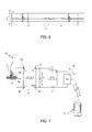
- the transduction signal S transd generated by the transducer 2, the voltage plot of which is shown in Figure 6 , has indeed a characteristic pattern at each step taken by the user.
- the aforesaid pattern envisages that a significant activity occurs (in terms of amplitude and/or duration of the signal) both in the positive portion of the signal and in the negative portion of the same signal, within a given analysis time interval, as a result of the initial impact of the foot with the ground and of the subsequent transfer of the weight of the body onto the other foot.
- this pattern envisages the presence of a first positive peak followed by a negative peak substantially of the same amplitude, and by a second positive peak of low amplitude, in turn followed by a subsequent step of rebound and settling (within the analysis time interval).
- the processing unit 8 thus executes an appropriate algorithm (by executing appropriate software instructions) for recognizing the occurrence of the aforesaid pattern in the transduction signal S transd and consequently detecting the occurrence of a step taken by the user.
- the aforesaid algorithm in general envisages monitoring, by the processing unit 8, of the signals having positive polarity and negative polarity, respectively (and thus designated by V pos and V neg ) present, respectively, on the first input terminal 5a and on the second input terminal 5b of the scavenger-interface stage 5 (or, likewise on the output terminals 4a, 4b of the transducer 2).
- the aforesaid signals Due to the switching operation of the scavenger-interface stage 5, the aforesaid signals have a so-called "choppered" pattern, i.e., they are constituted by a plurality of pulses with short duration, that is a function of the switching duty cycle, and an amplitude that is, in general, a function of the value of the output voltage V out stored in the storage capacitor 6.
- the value of the positive signal V pos is substantially zero during the operating condition of storage of energy in the inductor 15 (i.e., during a first portion of the switching period), and becomes almost instantaneously substantially equal to the output voltage V out on the storage capacitor 6 during the subsequent operating condition of transfer of energy to the storage capacitor 6 (i.e., during the second portion of the switching period); similar considerations apply to the negative signal V neg .
- the envelope of the positive and negative signals V pos , V neg thus follows the plot of the output voltage V out on the storage capacitor 6. Furthermore, the positive and negative signals V pos , V neg themselves are substantially zero, when the transduction signal S transd is also substantially zero, given that the current in the inductor I L does not reach the threshold value I th , and the switching operation is interrupted.
- the processing unit 8 is thus configured to determine the occurrence of a step in the case where a number of positive pulses (or, likewise, negative pulses) greater than a given counting threshold is detected - i.e., the presence of a significant number of positive (or negative) pulses is found - and further (within a pre-set time interval) a number of negative (or, likewise, positive) pulses greater than the counting threshold is consecutively detected - i.e., the presence of a significant number of negative (or positive) pulses is found.
- the processing unit 8 enables, as a function of said determination, a transmission operation, whereby information related to the increase of step count is sent to the portable apparatus 12 by the transmission stage 9; the portable apparatus 12 receives the transmission and processes its content to extract the step counting information.
- the step-counter device 1 may ideally be self-supplied, thanks to the presence of the efficient energy scavenging system, which supplies sufficient energy for step detection and for transmission of the step-counting information to the outside world (for example, to a portable electronic apparatus by Bluetooth wireless transmission).
- the number of components required is minimized, thanks to the absence of a battery or other electrical supply sources, and to the fact that the same transducer is used both for operations of energy scavenging from walking and for step detection and the consequent counting of the steps taken by the user as a function of the transduction signal.
- step detection no additional sensors, such as for example accelerometer sensors, are thus required. Consequently, the energy demand for operation of the step-counter device is minimized.
- the present Applicant has found that the aforesaid step-counting algorithm has a certain amount of complexity, which may entail the possibility of counting errors, and further a consumption of energy, by the processing unit 8, which could be excessive in certain situations. For instance, the situation could arise in which the electrical energy supplied by the scavenger-interface stage 5 and stored in the storage capacitor 6 is not sufficient for guaranteeing supply of the processing unit 8 for the time required for execution of the aforesaid algorithm.
- step-counter devices In general, the need is thus felt for further improvement of step-counter devices, in particular as regards the related energy efficiency and counting reliability.
- the aim of the present invention is to meet, at least in part, the above need.
- an energy scavenging step-counter device and a corresponding step-counting method are consequently provided, as defined in the annexed claims.
- the step-counter device 20 has a structure substantially similar to the one described with reference to Figure 1 , but with the difference that a processing unit is not envisaged in this embodiment.
- the step-counter device 20 thus comprises: a transducer 2, for energy scavenging, for example of an electromagnetic type and constituted by a permanently magnetized body 3 configured for moving within a coil 4 in response to mechanical stresses from the external environment, thus causing generation of a transduction signal S transd , in particular a voltage, between the output terminals 4a, 4b of the coil 4; a scavenger-interface stage 5, having a first input terminal 5a and a second input terminal 5b electrically coupled to a respective output terminal 4a, 4b of the transducer 2 for receiving the transduction signal S transd , and a first output terminal 5c and a second output terminal 5d, between which an output voltage V out is present; a capacitive storage element 6, connected between the aforesaid first and second output terminals 5c, 5d; a voltage
- no processing of the transduction signal S transd is carried out for determining the occurrence of a step; in fact, it is the very generation of electrical energy due to the step mechanical action, which results in the generation of the regulated voltage V reg , that is used for indicating the occurrence of a step.
- the transmission stage 9 is in fact supplied by the regulated voltage V reg and, once the regulated voltage V reg itself reaches a desired value, for example 1.8 V, it transmits to the outside world, for example by Bluetooth wireless communication, a signal indicating occurrence of the step. Consequently, the successful "transmission" event is designed to indicate occurrence of a step.
- a portable electronic apparatus 12 such as for example a smartphone, a tablet, a phablet, a portable computer, a digital audio player, a photographic camera, or a video camera, on the basis of the reception of the aforesaid transmission, is thus able to increment a step-counting signal.
- the aforesaid feature advantageously enables considerable simplification of the step detection, eliminating the signal processing required in prior art solutions, and thus the demand for electrical energy associated to the detection process is considerably reduced.
- a particular aspect of the present solution envisages that radio transmission is kept active for a pre-set time interval, in the presence of sufficient electrical energy, i.e., with the regulated voltage V reg that has a value sufficient to enable radio transmission.
- a load is activated, for example a load of a resistive type, for the voltage-regulating stage 7, which enables progressive reduction of the value of the regulated voltage V reg , as well as enabling the system to be brought back into the condition of being able to detect a new step.
- the solution described first envisages (step 30) that the regulated voltage V reg will reach, as a result of the operation of harvesting of mechanical energy and transformation thereof into electrical energy, a value sufficient for the transmission operation, i.e., not less than a given upper threshold value V th1 , for example 1.8 V.
- step 31 When the regulated voltage V reg exceeds the upper threshold value V th1 , from step 30 a step 31 is reached, where the transmission stage 9, supplied by the regulated voltage V reg , executes operations of initialization and configuration (of a known type, not described in detail herein). In particular, in this embodiment, the transmission stage 9 is able to configure itself for radio transmission. In the case where the value of the regulated voltage V reg is less than a given lower threshold value V th2 , for example 1.5 V, operation returns to step 30, for a sufficient increase of the same regulated voltage V neg .
- the transmission stage 9 transmits via radio to the outside world information associated to the increase of step counting (in the form of an appropriate signal), that may be received, for example, by the portable electronic apparatus 12.
- This information is solely a function of the fact that the value of the regulated voltage V reg has risen (and remains for the given interval) above the upper threshold value V th1 , and is not the result of signalprocessing operations (in particular of the transduction signal, here having solely an energy scavenging function).
- step 32 in the case where the value of the regulated voltage V reg is less than the lower threshold value V th2 , for example 1.5 V, operation returns to step 30, for a sufficient increase of the regulated voltage V neg .
- An aspect of the present solution envisages that the step of transmission by the transmission stage 9 remains active for a pre-set and fixed time interval, dependent on the characteristics of the same transmission stage 9.
- a load for example of a resistive type, is applied to remove any possible residual energy present in the system and cause the regulated voltage V reg to drop below the minimum value tolerated by the transmission stage 9 (equal to the lower threshold value V th2 ) in such a way that the system will be ready and reset for sensing a subsequent step.
- the same transmission stage 9 may be configured to activate the resistive load for the voltage-regulating stage 7.
- the processing unit 8 does not have processing functions aimed at step detection (an operation that is carried out, as described previously), but only the function of control and management of the transmission stage 9, in the case where the same transmission stage 9 is not, for example, able to undergo self-configuration and autonomously carry out operations of initialization and configuration.
- the solution described envisages once again (step 40) that the regulated voltage V reg reaches, as a result of the operation of harvesting of mechanical energy, a value sufficient for the operations of transmission, i.e., not lower than a given upper threshold value V th1 , for example 1.8 V.
- step 41 When the regulated voltage V reg exceeds the upper threshold value V th1 , from step 40 a step 41 is reached, where the processing unit 8, appropriately supplied by the regulated voltage V reg , executes operations of initialization and configuration (of a known type, here not described in detail). If in this step 41 the regulated voltage V reg drops below the lower threshold value V th2 , operation returns to step 40.
- the processing unit 8 controls the transmission stage 9 to perform appropriate operations of initialization and configuration. Also in this step 42, in the case where the value of the regulated voltage V reg is lower than the lower threshold value V th2 , operation returns to step 40 for an appropriate increase of the same regulated voltage V reg .
- the transmission stage 9 transmits via radio to the outside world the information of increase of step counting for the duration of the pre-set time interval (on the hypothesis that the regulated voltage remains above the lower threshold value V th2 ). After this, the residual energy is discharged by application of the load, for example of a resistive type for the voltage-regulating stage 7 (so that the regulated voltage drops below the lower threshold value V th2 ).
- FIGS 11 and 12 show, respectively, plots of the current and of the energy used by the step-counter device 20 during the operations described previously; in particular, T 1 is the time interval dedicated to the operations of initialization and configuration (by way of example, with reference to the second embodiment illustrated, where the processing unit 8 is present), whereas T 2 is the time interval dedicated to the operations of transmission of the step-counting information (and possible application of the load for discharging the residual energy present in the system).
- Figure 13 further shows, by way of example, a possible time plot of the output voltage V out generated by the scavenger-interface stage 5, and of the regulated voltage V reg , where once again T 1 is the time interval dedicated to the operations of initialization and configuration, and T 2 is the time interval dedicated to the operations of transmission of the step-counting information.
- the regulated voltage V reg which is stable at a value sufficient to enable step-counting operations during the aforesaid intervals T 1 and T 2 , decreases until it substantially goes to zero, starting from the end of the same interval T 2 .
- the solution described provides a step-counter device without batteries, in so far as it may be self-supplied thanks to the efficient system for scavenging mechanical energy, and furthermore without additional sensors, for example of an accelerometer type.
- the step-counter device is improved as regards energy efficiency and reliability, for example in so far as it does not require any processing of signals (not even of the signal transduced by the energy scavenger interface) for sensing and counting the steps; it is in fact the correct and complete transmission of the count-increment signal by the transmission stage 9 that indicates occurrence of a step.
- a possible embodiment does not even envisage a processing unit, given that no signal processing is required and given that a transmission stage is used capable of self-configuration and self-initialization. In this case, energy consumption proves to be even lower.
- the solution described enables detection of the occurrence of steps both when the user is running and when the user is walking.
- the solution described may be used also with different types of transducers, for example of a piezoelectric type, using in any case the same transducer both for energy scavenging and for step detection.
- the scavenger-interface stage 5 could be different from what has been illustrated; for example, it could have a different circuit configuration, capable in any case of ensuring generation of the regulated voltage V reg , at least for supply of the transmission stage 9 (and, if present, of the processing unit 8).
- the portable electronic apparatus 12 which receives the step-counting signal from the step-counter device 20, may be configured to carry out further processing operations starting from the same signal.
Landscapes
- Engineering & Computer Science (AREA)
- Combustion & Propulsion (AREA)
- Chemical & Material Sciences (AREA)
- Physics & Mathematics (AREA)
- General Physics & Mathematics (AREA)
- Power Engineering (AREA)
- Computer Networks & Wireless Communication (AREA)
- Radar, Positioning & Navigation (AREA)
- Remote Sensing (AREA)
- Mechanical Engineering (AREA)
- General Engineering & Computer Science (AREA)
- Health & Medical Sciences (AREA)
- Toxicology (AREA)
- Charge And Discharge Circuits For Batteries Or The Like (AREA)
- Telephone Function (AREA)
Abstract
Description
- The present invention is directed to a step-counter device, a so-called "pedometer", provided with energy scavenging (or energy-harvesting) operation, thus having self-supply capability, i.e., being able to autonomously provide for its own supply of electrical energy. The present invention further relates to a step-counting method.
- Step-counter devices are known, which, either worn or otherwise carried by a user, enable measurement of the number of steps taken and calculation of the distance travelled, as well as providing additional information, such as for example average speed or consumption of calories.
- Step-counter devices are, for example, used in inertial navigation systems (the so-called "dead-reckoning" systems) applied to humans, in applications in the clinical field (for example, rehabilitation), and in general in the fitness field (as instruments for monitoring physical activity performed by the user).
- In particular, step-counter devices are known, using integrated accelerometers of the MEMS (Micro-ElectroMechanical System) type for detecting steps.
- These devices have particularly compact dimensions, so that they may be conveniently worn by the user, for example being integrated in the user footwear.
- The aforesaid step-counter devices implement a method for detecting steps based on the analysis of the pattern of a vertical acceleration signal that is generated during the various phases of the gait cycle, due to impact of the foot on the ground, and that is detected by the accelerometer fixed with respect to the body of the user. In particular, occurrence of a step is determined by identifying acceleration peaks that appear in the acceleration signal, and these peaks are identified by comparing the acceleration signal with a given reference threshold.
- Notwithstanding the use of MEMS sensors, with reduced energy consumption, known step-counter devices require a source of supply, typically a battery, for their use and for transmission of the information detected to external devices (for example, a portable electronic apparatus, such as a smartphone, a PDA, a tablet, a digital audio player, a photographic camera, or a video camera).
- Further known are solutions for scavenging energy from environmental energy sources, and in particular for conversion of mechanical energy originating from such sources into electrical energy. Such solutions have aroused considerable interest in a wide range of technological fields, given the ever-increasing demand for miniaturization of electronic systems, in particular portable ones, and the corresponding need for supplying these electronic systems with batteries of small dimensions or, wherever possible, with supply sources of their own (the so-called "self-supply"), without the aid of additional energy sources (for example, one or more batteries).
- Mechanical energy is converted by one or more energy scavenging transducers (for example, piezoelectric or electromagnetic transducers) into electrical energy, which may then be used, after appropriate operations of conversion and processing, for supplying an electrical load. In this way, the same electrical load does not require batteries or other additional supply systems. For instance, low-frequency vibrations, such as for example mechanical vibrations in systems with moving parts, may constitute a valid source of energy.
- For instance, systems have been proposed for recovery of energy from the human gait, by appropriate energy-harvesting systems housed inside, or coupled to, the shoes of a user.
- In this regard, the following documents may for example be cited: "Shoe-mounted PVDF Piezoelectric Transducer for Energy Harvesting" by D. Fourie, MIT Undergraduate Research Journal 19, pp. 66-70, Spring 2010; or "Energy Scavenging with Shoe-Mounted Piezoelectrics" by N.S. Shenck, J.A. Paradiso, Micro, IEEE, vol. 21, No. 3, pp. 30-42, May/June 2001.
- The above systems envisage, by piezoelectric transducers, recovery of part of the mechanical energy dissipated when the foot strikes the ground during walking. The energy recovered may, for example, be used for supplying portable electronic devices, or else for activating and sustain wireless transmission of information.
- In patent application No.
US 14/034.764, filed on September 24, 2013 TO2012A000833, filed on September 26, 2012 - In particular, the solution proposed in the aforesaid patent application envisages implementing, in the step-counter device, an energy scavenging system, including a transducer of mechanical energy into electrical energy, in particular of an electromagnetic type, and use of the same transducer as a sensor for detecting the step of the user, on the basis of which step counting may be carried out (step counting is indeed a function of processing of the transduced signal).
- The step-counter device is thus extremely compact and efficient from the energy standpoint, given that it has self-supply capability, without the need for resorting to an external supply source, for example a battery, and without the need for further sensors for step detection.
- As illustrated in
Figure 1 , the aforesaid step-counter device, designated as a whole by 1, comprises atransducer 2 for energy scavenging, for example of an electromagnetic type, illustrated schematically and constituted in a per se known manner by abody 3, having permanent magnetization, configured to move within acoil 4, in response to mechanical stresses coming from the external environment, thus causing generation of a transduction signal Stransd, in particular a voltage signal, between theoutput terminals same coil 4. - In particular, the
transducer 2 is designed to be coupled to a shoe of a user, in such a way as to be subject to mechanical stresses due to the steps taken by the user and to the impact of the foot on the ground. - The step-
counter device 1 further comprises a scavenger-interface stage 5, and acapacitive storage element 6. - The scavenger-
interface stage 5 has afirst input terminal 5a and asecond input terminal 5b electrically coupled to arespective output terminal transducer 2 for receiving the transduction signal Stransd, and afirst output terminal 5c and asecond output terminal 5d, connected between which is thestorage capacitor 6; an output voltage Vout is present between the same output terminals. - The step-
counter device 1 further comprises: a voltage-regulatingstage 7, for example constituted by a DC/DC converter, which receives at its input the output voltage Vout and supplies a regulated voltage Vreg, for example having a value of 1.8 V; aprocessing unit 8, for example a microprocessor or microcontroller unit (or similar computing unit, for example including an FPGA - field-programmable gate array); and atransmission stage 9, coupled to a transmittingantenna 10, configured for radio (or wireless) transmission. - The
processing unit 8 is supplied by the regulated voltage Vreg (generated based on the transduction signal Stransd) and is further connected to the first andsecond input terminals interface stage 5 for receiving the same transduction signal Stransd. Theprocessing unit 8 is configured to execute an appropriate algorithm for detecting the occurrence of a step as a function of the characteristics of the aforesaid transduction signal Stransd generated by thetransducer 2 for performing the function of counting the steps of the user. - The
processing unit 8 is further configured to actuate thetransmission stage 9, and the corresponding transmittingantenna 10, for remote wireless transmission of the processed information regarding counting of the steps of the user as a function of the transduction signal Stransd, for example with Bluetooth (BT) transmission technology, or other technology of a known type, for example IR, Wi-Fi, NFC, or the like. - As illustrated schematically, this information may be sent to a portable
electronic apparatus 12, such as for example a smartphone, a tablet, a phablet, a portable computer, a digital audio player, a photographic camera, or a video camera, including a processor or similar processing device, for display by the user and/or for execution of further processing operations and activation of functions of the same portableelectronic apparatus 12. - The step-
counter device 1 may comprise a single package, designed to house all the elementary components described previously and designed to be coupled in an appropriate way to the user, for example to be arranged within the shoe, embedded in the sole; alternatively, the step-counter device 1 may comprise distinct packages, for example for thetransducer 2 and for the remaining electronic circuitry associated thereto. - The scavenger-
interface stage 5 is in general configured to convert the transduction signal Stransd, generated by thetransducer 12 following upon the action of transduction of the mechanical energy associated to the step, into a form useful for energy scavenging and subsequent generation of the regulated voltage Vreg by the voltage-regulatingstage 7, with the aim of maximizing the efficiency of conversion and in general of the energy scavenging action. - For instance, the scavenger-
interface stage 5 is made as described in patent application No.US2012/307538 A1 , filed in the name of the present Applicant. - As illustrated in
Figure 2 , the scavenger-interface stage 5 provides in this case a switching converter of a fully active boost type, which directly exploits the intrinsic inductance of thetransducer 2, the latter being indeed modelled as avoltage generator 14, designed to supply a voltage Vtransd (corresponding to the transduction signal Stransd) and connected in series to aninductor 15, having a characteristic inductance Ls, and to aresistor 16, having a characteristic resistance Rs. - The scavenger-
interface stage 5 comprises two pairs of switches, functionally coupled to one another, and a logic control unit, designed to control switching thereof for cyclic management of storage of energy in theinductor 15 and its transfer to thestorage capacitor 6, for both polarities, positive and negative, of voltage Vtransd. The switches are active switches, made with high-voltage transistors, for example N-channel MOSFETs. - In detail, a first pair of switches includes: a
first switch 18a, connected between thefirst input terminal 5a and a reference terminal GND (for example, connected to the electrical ground of the circuit); and asecond switch 18b, connected between thefirst input terminal 5a and thefirst output terminal 5c and to the storage capacitor 6 (thesecond output terminal 5d is connected to the reference terminal GND). - The second pair of switches includes: a
third switch 18c, connected between thesecond input terminal 5b and the reference terminal GND; and afourth switch 18d, connected between the samesecond input terminal 5b and thefirst output terminal 5c and to thestorage capacitor 6. - Each
switch 18a-18d has a respective control terminal that receives a respective control signal from the logic control unit, designated by 19. - In the case of positive polarity of voltage Vtransd, the
logic control unit 19 keeps thethird switch 18c closed and thefourth switch 18d open and controls switching of the first pair ofswitches inductor 15, by closing thefirst switch 18a (with thesecond switch 18b open), and subsequently causing transfer thereof to thestorage capacitor 6, by closing thesecond switch 18b (and opening thefirst switch 18a). - Operation is altogether symmetrical and specular as regards the negative polarity of the voltage Vtransd, with the
logic control unit 19 that keeps thefirst switch 18a closed and thesecond switch 18b open, and controls switching of the second pair ofswitches inductor 15, by closing thethird switch 18c, and subsequently causing transfer thereof to thestorage capacitor 6, by closing thefourth switch 18d. - Switching timing of
switches 18a-18d is managed by thelogic control unit 19 in such a way as to maximize the coupling efficiency between thetransducer 2 and the scavenger-interface stage 5, and the efficiency of the transfer of energy to thestorage capacitor 6. - To explain the control algorithm executed by the
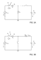
logic control unit 19 reference may be made, given the symmetry of the circuit, to the circuit model of half of the circuit, shown inFigures 3a and 3b , respectively in the case of the operating condition of storage of energy in theinductor 15, and in the case of the operating condition of transfer of the energy stored to the storage capacitor 6 (in this model, RON is the resistance in a closed state of thefirst switch 18a or thesecond switch 18b, each time driven into a closing condition). - In particular, also with reference to
Figure 4a , related to the operating condition ofFigure 3a , during storage of energy in theinductor 15, the current circulating in thesame inductor 15, designated by IL, increases until it reaches a peak value ION, after a time interval Tdelay has elapsed, starting from the start of the storage operating condition. Thelogic control unit 19 controls, by means of the switches, the end of the storage operating condition after the time interval Tdelay has elapsed and a minimum threshold value Ith has been exceeded by the current in the inductor IL. - The threshold value Ith is chosen much lower than the peak value ION that is expected to be reached in the application in which the circuit is used. For instance, assuming that peak values ION of approximately 150 mA are reached, the threshold value Ith may be chosen to be comprised between approximately 5 and 10 mA (given that the choice of a threshold value Ith too close to the peak value ION entails a low efficiency).
- Next, as illustrated in
Figure 4b , in the operating condition of transfer of energy, the current in the inductor IL, which coincides with the current, designated by IOUT, that flows in thestorage capacitor 6, decreases until it reaches a lower limit value IOFF, whereby thelogic control unit 19 controls a new switching of the switches, to return, in a cyclic way, into the operating condition of storage of energy in theinductor 15. - In particular, the aforesaid lower limit value IOFF is equal to a fraction k (with k > 1) of the peak value ION

- As discussed in detail in the aforesaid patent application No.
US 2012/307538 A1 , thelogic control unit 19, with an appropriate choice of the time interval Tdelay and of the factor k, is able to act upon the mean value and the ripple of the current in the inductor IL. - In particular, the
logic control unit 19 is able to determine optimal values of time interval Tdelay and of factor k such as to minimize the ripple in the pattern of the inductor current IL, represented with a solid line inFigure 5 , and maximize matching between the inductor current IL and the current on a matched load (represented with a dashed line in the sameFigure 5 ). - The
logic control unit 19 thus ensures the best matching (η ≈ 1) between thetransducer 2 and the scavenger-interface stage 5 (the output of thetransducer 2 and the input of the scavenger-interface stage 5 have, that is, substantially the same impedance), maximizing the efficiency of transfer of power between input and output of the scavenger-interface stage 5, in each cycle of charging/discharging of theinductor 15. - As previously highlighted, the
processing unit 8 of the step-counter device 1, which is appropriately supplied thanks to the action of the scavenger-interface stage 5 starting from the transduction signal Stransd, is able to detect the occurrence of a step as a function of processing of the characteristics of the same transduction signal Strand. - The transduction signal Stransd generated by the
transducer 2, the voltage plot of which is shown inFigure 6 , has indeed a characteristic pattern at each step taken by the user. - In particular, the aforesaid pattern envisages that a significant activity occurs (in terms of amplitude and/or duration of the signal) both in the positive portion of the signal and in the negative portion of the same signal, within a given analysis time interval, as a result of the initial impact of the foot with the ground and of the subsequent transfer of the weight of the body onto the other foot. For instance, this pattern envisages the presence of a first positive peak followed by a negative peak substantially of the same amplitude, and by a second positive peak of low amplitude, in turn followed by a subsequent step of rebound and settling (within the analysis time interval).
- The
processing unit 8 thus executes an appropriate algorithm (by executing appropriate software instructions) for recognizing the occurrence of the aforesaid pattern in the transduction signal Stransd and consequently detecting the occurrence of a step taken by the user. - The aforesaid algorithm in general envisages monitoring, by the
processing unit 8, of the signals having positive polarity and negative polarity, respectively (and thus designated by Vpos and Vneg) present, respectively, on thefirst input terminal 5a and on thesecond input terminal 5b of the scavenger-interface stage 5 (or, likewise on theoutput terminals - Due to the switching operation of the scavenger-
interface stage 5, the aforesaid signals have a so-called "choppered" pattern, i.e., they are constituted by a plurality of pulses with short duration, that is a function of the switching duty cycle, and an amplitude that is, in general, a function of the value of the output voltage Vout stored in thestorage capacitor 6. - In particular, the value of the positive signal Vpos is substantially zero during the operating condition of storage of energy in the inductor 15 (i.e., during a first portion of the switching period), and becomes almost instantaneously substantially equal to the output voltage Vout on the
storage capacitor 6 during the subsequent operating condition of transfer of energy to the storage capacitor 6 (i.e., during the second portion of the switching period); similar considerations apply to the negative signal Vneg. - The envelope of the positive and negative signals Vpos, Vneg thus follows the plot of the output voltage Vout on the
storage capacitor 6. Furthermore, the positive and negative signals Vpos, Vneg themselves are substantially zero, when the transduction signal Stransd is also substantially zero, given that the current in the inductor IL does not reach the threshold value Ith, and the switching operation is interrupted. - The
processing unit 8 is thus configured to determine the occurrence of a step in the case where a number of positive pulses (or, likewise, negative pulses) greater than a given counting threshold is detected - i.e., the presence of a significant number of positive (or negative) pulses is found - and further (within a pre-set time interval) a number of negative (or, likewise, positive) pulses greater than the counting threshold is consecutively detected - i.e., the presence of a significant number of negative (or positive) pulses is found. - Once occurrence of a step has been determined, the
processing unit 8 enables, as a function of said determination, a transmission operation, whereby information related to the increase of step count is sent to theportable apparatus 12 by thetransmission stage 9; theportable apparatus 12 receives the transmission and processes its content to extract the step counting information. - Advantageously, in the solution described previously, the step-
counter device 1 may ideally be self-supplied, thanks to the presence of the efficient energy scavenging system, which supplies sufficient energy for step detection and for transmission of the step-counting information to the outside world (for example, to a portable electronic apparatus by Bluetooth wireless transmission). - The number of components required is minimized, thanks to the absence of a battery or other electrical supply sources, and to the fact that the same transducer is used both for operations of energy scavenging from walking and for step detection and the consequent counting of the steps taken by the user as a function of the transduction signal.
- For step detection, no additional sensors, such as for example accelerometer sensors, are thus required. Consequently, the energy demand for operation of the step-counter device is minimized.
- However, the solution described has some potentially disadvantageous characteristics, which may preclude the possibility of fully achieving the aforesaid advantages.
- In particular, the present Applicant has found that the aforesaid step-counting algorithm has a certain amount of complexity, which may entail the possibility of counting errors, and further a consumption of energy, by the
processing unit 8, which could be excessive in certain situations. For instance, the situation could arise in which the electrical energy supplied by the scavenger-interface stage 5 and stored in thestorage capacitor 6 is not sufficient for guaranteeing supply of theprocessing unit 8 for the time required for execution of the aforesaid algorithm. - In general, the need is thus felt for further improvement of step-counter devices, in particular as regards the related energy efficiency and counting reliability.
- The aim of the present invention is to meet, at least in part, the above need.
- According to the present invention, an energy scavenging step-counter device, and a corresponding step-counting method are consequently provided, as defined in the annexed claims.
- For a better understanding of the present invention, preferred embodiments thereof are now described, purely by way of nonlimiting example and with reference to the attached drawings, wherein:
-
Figure 1 shows a block diagram of a step-counter device provided with an energy scavenging system; -
Figure 2 shows an equivalent circuit diagram of an energy scavenger interface stage in the step-counter device ofFigure 1 ; -
Figures 3a and 3b are circuit models of the interface stage ofFigure 2 , in respective operating conditions; -
Figures 4a and 4b show plots of electric currents in the interface stage ofFigure 2 , referred to the circuit models ofFigures 3a and 3b , respectively; -
Figure 5 shows the plot of an electrical output quantity in the interface stage ofFigure 2 ; -
Figure 6 shows the plot of an electrical transduction signal generated by a transducer of the step-counter device ofFigure 1 ; -
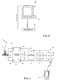
Figure 7 shows a block diagram of a step-counter device provided with an energy scavenging system, according to a first embodiment of the present solution; -
Figure 8 shows a flowchart of step-counting operations performed in the device ofFigure 8 ; -
Figure 9 shows a block diagram of a step-counter device provided with an energy scavenging system, according to a second embodiment of the present solution; -
Figure 10 shows a flowchart of step-counting operations performed in the device ofFigure 9 ; and -
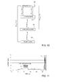
Figures 11-13 show the plots of electrical quantities associated to step counting. - With reference to
Figure 7 , a description of a step-counter device, designated by 20, according to a first embodiment of the present solution is now presented (the same reference numbers will be used hereinafter for designating elements that are similar to corresponding elements described previously and that will not be described again). - The step-
counter device 20 has a structure substantially similar to the one described with reference toFigure 1 , but with the difference that a processing unit is not envisaged in this embodiment. The step-counter device 20 thus comprises: atransducer 2, for energy scavenging, for example of an electromagnetic type and constituted by a permanentlymagnetized body 3 configured for moving within acoil 4 in response to mechanical stresses from the external environment, thus causing generation of a transduction signal Stransd, in particular a voltage, between theoutput terminals coil 4; a scavenger-interface stage 5, having afirst input terminal 5a and asecond input terminal 5b electrically coupled to arespective output terminal transducer 2 for receiving the transduction signal Stransd, and afirst output terminal 5c and asecond output terminal 5d, between which an output voltage Vout is present; acapacitive storage element 6, connected between the aforesaid first andsecond output terminals stage 7, for example constituted by a DC/DC converter, which receives at its input the output voltage Vout and supplies at its output a regulated voltage Vreg, for example having a value of 1.8 V; and atransmission stage 9, supplied by the voltage-regulatingstage 7 and coupled to a transmittingantenna 10, configured for wireless transmission, for example using the Bluetooth protocol. - According to a particular aspect of the present solution, unlike known solutions, no processing of the transduction signal Stransd is carried out for determining the occurrence of a step; in fact, it is the very generation of electrical energy due to the step mechanical action, which results in the generation of the regulated voltage Vreg, that is used for indicating the occurrence of a step.
- The
transmission stage 9 is in fact supplied by the regulated voltage Vreg and, once the regulated voltage Vreg itself reaches a desired value, for example 1.8 V, it transmits to the outside world, for example by Bluetooth wireless communication, a signal indicating occurrence of the step. Consequently, the successful "transmission" event is designed to indicate occurrence of a step. - A portable
electronic apparatus 12, such as for example a smartphone, a tablet, a phablet, a portable computer, a digital audio player, a photographic camera, or a video camera, on the basis of the reception of the aforesaid transmission, is thus able to increment a step-counting signal. - The aforesaid feature advantageously enables considerable simplification of the step detection, eliminating the signal processing required in prior art solutions, and thus the demand for electrical energy associated to the detection process is considerably reduced.
- A particular aspect of the present solution envisages that radio transmission is kept active for a pre-set time interval, in the presence of sufficient electrical energy, i.e., with the regulated voltage Vreg that has a value sufficient to enable radio transmission. After this period, a load is activated, for example a load of a resistive type, for the voltage-regulating
stage 7, which enables progressive reduction of the value of the regulated voltage Vreg, as well as enabling the system to be brought back into the condition of being able to detect a new step. - In greater detail, and with reference to
Figure 8 , the solution described first envisages (step 30) that the regulated voltage Vreg will reach, as a result of the operation of harvesting of mechanical energy and transformation thereof into electrical energy, a value sufficient for the transmission operation, i.e., not less than a given upper threshold value Vth1, for example 1.8 V. - When the regulated voltage Vreg exceeds the upper threshold value Vth1, from step 30 a
step 31 is reached, where thetransmission stage 9, supplied by the regulated voltage Vreg, executes operations of initialization and configuration (of a known type, not described in detail herein). In particular, in this embodiment, thetransmission stage 9 is able to configure itself for radio transmission. In the case where the value of the regulated voltage Vreg is less than a given lower threshold value Vth2, for example 1.5 V, operation returns to step 30, for a sufficient increase of the same regulated voltage Vneg. - At the end of the configuration operations, in a
step 32, subsequent to step 31, thetransmission stage 9 transmits via radio to the outside world information associated to the increase of step counting (in the form of an appropriate signal), that may be received, for example, by the portableelectronic apparatus 12. This information is solely a function of the fact that the value of the regulated voltage Vreg has risen (and remains for the given interval) above the upper threshold value Vth1, and is not the result of signalprocessing operations (in particular of the transduction signal, here having solely an energy scavenging function). - Once again, also in this
step 32, in the case where the value of the regulated voltage Vreg is less than the lower threshold value Vth2, for example 1.5 V, operation returns to step 30, for a sufficient increase of the regulated voltage Vneg. - An aspect of the present solution envisages that the step of transmission by the
transmission stage 9 remains active for a pre-set and fixed time interval, dependent on the characteristics of thesame transmission stage 9. - Afterwards, a load, for example of a resistive type, is applied to remove any possible residual energy present in the system and cause the regulated voltage Vreg to drop below the minimum value tolerated by the transmission stage 9 (equal to the lower threshold value Vth2) in such a way that the system will be ready and reset for sensing a subsequent step. For instance, the
same transmission stage 9 may be configured to activate the resistive load for the voltage-regulatingstage 7. - No additional checks or operations are thus envisaged for determining end of the transmission operation, which is instead determined by the end of the pre-set time interval (after which the aforesaid operations are repeated for sensing of a new step occurrence).
- It should be noted that such a solution prevents the possibility of spurious signals being transmitted to the portable
electronic apparatus 12 that might indicate erroneous step detection. In fact, the transmission is successful, and a signal for incrementing the step count is thus interpreted correctly by the receiver, only in the case where it is possible to execute the transmission until, the end of the time interval envisaged. - With reference to
Figure 9 , a further embodiment of the present solution is now described, which envisages the use of a processing unit, once again designated by 8, coupled to thetransmission stage 9 and supplied by the regulated voltage Vreg. - The
processing unit 8, however, does not have processing functions aimed at step detection (an operation that is carried out, as described previously), but only the function of control and management of thetransmission stage 9, in the case where thesame transmission stage 9 is not, for example, able to undergo self-configuration and autonomously carry out operations of initialization and configuration. - In this case (see also
Figure 10 ), the solution described envisages once again (step 40) that the regulated voltage Vreg reaches, as a result of the operation of harvesting of mechanical energy, a value sufficient for the operations of transmission, i.e., not lower than a given upper threshold value Vth1, for example 1.8 V. - When the regulated voltage Vreg exceeds the upper threshold value Vth1, from step 40 a
step 41 is reached, where theprocessing unit 8, appropriately supplied by the regulated voltage Vreg, executes operations of initialization and configuration (of a known type, here not described in detail). If in thisstep 41 the regulated voltage Vreg drops below the lower threshold value Vth2, operation returns to step 40. - Once the configuration step ends, the processing unit 8 (at step 42) controls the
transmission stage 9 to perform appropriate operations of initialization and configuration. Also in thisstep 42, in the case where the value of the regulated voltage Vreg is lower than the lower threshold value Vth2, operation returns to step 40 for an appropriate increase of the same regulated voltage Vreg. - At the end of the configuration operations, in a
step 43, subsequent to step 42, thetransmission stage 9 transmits via radio to the outside world the information of increase of step counting for the duration of the pre-set time interval (on the hypothesis that the regulated voltage remains above the lower threshold value Vth2). After this, the residual energy is discharged by application of the load, for example of a resistive type for the voltage-regulating stage 7 (so that the regulated voltage drops below the lower threshold value Vth2). -
Figures 11 and12 show, respectively, plots of the current and of the energy used by the step-counter device 20 during the operations described previously; in particular, T1 is the time interval dedicated to the operations of initialization and configuration (by way of example, with reference to the second embodiment illustrated, where theprocessing unit 8 is present), whereas T2 is the time interval dedicated to the operations of transmission of the step-counting information (and possible application of the load for discharging the residual energy present in the system). - The plots shows that, in the example illustrated, a minimal energy of just 70 µJ is sufficient for proper transmission of the step-counting information, in the solution that envisages the presence of the
processing unit 8. It is evident that the minimum value of energy is lower in the case where the solution does not envisage the use ofprocessing unit 8. -
Figure 13 further shows, by way of example, a possible time plot of the output voltage Vout generated by the scavenger-interface stage 5, and of the regulated voltage Vreg, where once again T1 is the time interval dedicated to the operations of initialization and configuration, and T2 is the time interval dedicated to the operations of transmission of the step-counting information. - In particular, it may be noted that the regulated voltage Vreg, which is stable at a value sufficient to enable step-counting operations during the aforesaid intervals T1 and T2, decreases until it substantially goes to zero, starting from the end of the same interval T2.
- The advantages of the step-counter device and of the related step-counting method are clear from the foregoing discussion.
- In general, it is emphasized once again that the solution described provides a step-counter device without batteries, in so far as it may be self-supplied thanks to the efficient system for scavenging mechanical energy, and furthermore without additional sensors, for example of an accelerometer type.
- The step-counter device is improved as regards energy efficiency and reliability, for example in so far as it does not require any processing of signals (not even of the signal transduced by the energy scavenger interface) for sensing and counting the steps; it is in fact the correct and complete transmission of the count-increment signal by the
transmission stage 9 that indicates occurrence of a step. - In particular, a possible embodiment does not even envisage a processing unit, given that no signal processing is required and given that a transmission stage is used capable of self-configuration and self-initialization. In this case, energy consumption proves to be even lower.
- Furthermore, advantageously, the solution described enables detection of the occurrence of steps both when the user is running and when the user is walking.
- Finally, it is clear that modifications and variations may be made to what has been described and illustrated herein, without thereby departing from the scope of the present invention, as defined in the annexed claims.
- In particular, the solution described may be used also with different types of transducers, for example of a piezoelectric type, using in any case the same transducer both for energy scavenging and for step detection.
- The scavenger-
interface stage 5 could be different from what has been illustrated; for example, it could have a different circuit configuration, capable in any case of ensuring generation of the regulated voltage Vreg, at least for supply of the transmission stage 9 (and, if present, of the processing unit 8). - Furthermore, it is evident that the portable
electronic apparatus 12, which receives the step-counting signal from the step-counter device 20, may be configured to carry out further processing operations starting from the same signal.
Claims (18)
- A step-counter device (20) for counting the steps of a user, comprising:a energy scavenging transducer (2), configured to generate an electrical transduction signal (Stransd) as a function of the mechanical activity generated during the steps;an energy scavenging stage (5, 6), coupled to said transducer (2) to generate electrical energy starting from the mechanical activity generated during each step, configured to supply an output supply signal (Vout) starting from said electrical transduction signal (Stransd);a regulator stage (7), configured to generate a regulated supply signal (Vreg) starting from said output supply signal (Vout); anda radio transmission stage (9), supplied by said regulator stage (7),characterized in that said transmission stage (9) is configured to implement a transmission, to the outside world, of a count-increment signal due to exceeding of a first threshold (Vth1) by the regulated supply signal (Vreg), said transmission having a pre-set duration, whose completion is indicative of the occurrence of a step and designed to increment said step counting.
- The device according to claim 1, wherein said transmission stage (9) is configured to carry out an operation of initialization when the value of the regulated supply signal (Vreg) is higher than the first threshold (Vth1) and to carry out said transmission for a pre-set time interval, during which the value of the regulated supply signal (Vreg) is not lower than a second threshold (Vth2).
- The device according to claim 2, wherein said transmission stage (9) is configured to cause an operation of discharge of a residual electrical energy, at the end of the pre-set time interval.
- The device according to any one of the preceding claims, wherein said count-increment signal is not a function of any signal processing, on the basis of said electrical transduction signal (Stransd)
- The device according to any one of the preceding claims, wherein said transmission stage (9) is self-configurable and able to carry out autonomously an initialization operation, when supplied by said regulated supply signal (Vreg) having a value higher than said first threshold (Vth1).
- The device according to claim 5, wherein said transmission stage (9) is configured to start transmission of said count-increment signal after a time interval (T1) associated to said initialization operation.
- The device according to any one of the preceding claims, having no processing unit coupled to said transmission stage (9).
- The device according to any one of claims 1-4, further comprising a processing unit (8), coupled to said transmission stage (9) and designed to configure said transmission stage (9) for transmission of said count-increment signal, when supplied by said regulated supply signal (Vreg) having a value higher than said first threshold (Vth1).
- The device according to claim 8, wherein said processing unit (8) is configured so as not to carry out any signal processing, on the basis of said electrical transduction signal (Stransd).
- The device according to any one of the preceding claims, wherein said transducer (2) is of an electromagnetic type and has a characteristic inductance (Ls); and wherein said energy scavenging stage (5, 6) comprises an interface stage (5), which has a first input terminal (5a) and a second input terminal (5b) coupled to said transducer (2) and is configured to define a switching converter using the characteristic inductance (Ls) of said transducer (2).
- The device according to claim 10, wherein said energy scavenging stage (5, 6) comprises a storage capacitor (6) on which said output supply signal (Vout) is present, connected between a first output terminal (5c) and a second output terminal (5d) of said interface stage (5); and wherein said interface stage (5) comprises a logic control unit (19) and a switch assembly (18a-18d), whose switching is controlled by said logic control unit (19) for causing cyclically storage of energy in said inductor (15) in a first interval of a switching period, and transfer of energy onto said storage capacitor (6) in a second interval of the switching period, at both polarities, positive and negative, of the electrical transduction signal (Stransd)
- The device according to claim 11, wherein said logic control unit (19) is configured to control switching of said switch assembly (18a-18d) to optimize a coupling efficiency between said transducer (2) and said interface stage (5).
- The device according to any one of the preceding claims, designed to be coupled to an item of footwear of said user.
- A system for counting the steps taken by a user, comprising the step-counter device (20) according to any of the preceding claims, and a processing device (12) configured to receive said count-increment signal and determine an increment of said step counting as a function of completion of said transmission, having a pre-set duration.
- A method for counting the steps taken by a user, comprising the steps of:performing an operation of transduction, for generating an electrical transduction signal (Stransd) as a function of the mechanical activity generated during the steps;performing an energy scavenging operation starting from said mechanical activity generated during each step, for generation of an output supply signal (Vout) starting from said electrical transduction signal (Stransd); andgenerating a regulated supply signal (Vreg) starting from said output supply signal (Vout),characterized by comprising the step of implementing a transmission to the outside world of a count-increment signal due to exceeding of a first threshold (Vth1) by the regulated supply signal (Vreg), wherein said transmission has a pre-set duration, whose completion is indicative of the occurrence of a step and designed to increment said step counting.
- The method according to claim 15, wherein the transmission step is executed as a function of the fact that the value of the regulated supply signal (Vreg) increases above the first threshold (Vth1) and is not lower than a second threshold (Vth2) for a pre-set time interval.
- The method according to claim 15 or claim 16, wherein the transmission step is not a function of any signal processing, on the basis of said electrical transduction signal (Stransd).
- The method according to any of the claims 15-17, comprising receiving said count-increment signal and determining an increment of said step counting as a function of completion of said transmission, having a pre-set duration.
Applications Claiming Priority (1)
| Application Number | Priority Date | Filing Date | Title |
|---|---|---|---|
| ITTO20140202 | 2014-03-13 |
Publications (1)
| Publication Number | Publication Date |
|---|---|
| EP2918975A1 true EP2918975A1 (en) | 2015-09-16 |
Family
ID=50639834
Family Applications (1)
| Application Number | Title | Priority Date | Filing Date |
|---|---|---|---|
| EP15159116.1A Withdrawn EP2918975A1 (en) | 2014-03-13 | 2015-03-13 | Energy scavenging step-counter device and related step-counting method |
Country Status (2)
| Country | Link |
|---|---|
| US (1) | US20150260542A1 (en) |
| EP (1) | EP2918975A1 (en) |
Families Citing this family (2)
| Publication number | Priority date | Publication date | Assignee | Title |
|---|---|---|---|---|
| CN106895835B (en) | 2015-12-17 | 2021-01-22 | 阿里巴巴集团控股有限公司 | Positioning method and device |
| CN108953081A (en) * | 2018-06-01 | 2018-12-07 | 四川斐讯信息技术有限公司 | A kind of method of supplying power to and device for persistently remembering step for pedometer |
Citations (7)
| Publication number | Priority date | Publication date | Assignee | Title |
|---|---|---|---|---|
| US5797201A (en) * | 1997-07-24 | 1998-08-25 | Huang; Tien-Tsai | Shoe with step counting capability |
| US6438193B1 (en) * | 1998-07-10 | 2002-08-20 | Wen H. Ko | Self-powered tire revolution counter |
| JP2007004577A (en) * | 2005-06-24 | 2007-01-11 | Seiko Epson Corp | Integrated circuit device, pedometer |
| US20100090477A1 (en) * | 2008-10-08 | 2010-04-15 | Keating Joseph A | Foot-Powered Footwear-Embedded Sensor-Transceiver |
| EP2458338A1 (en) * | 2010-11-25 | 2012-05-30 | Silicon Valley Micro E Corporation | Pedometer With Shoe Mounted Sensor And Transmitter |
| EP2530822A1 (en) * | 2011-05-30 | 2012-12-05 | STMicroelectronics S.r.l. | Energy scavenging interface, method for operating the energy scavenging interface, and energy harvesting system comprising the energy scavenging interface |
| US20130191069A1 (en) * | 2012-01-19 | 2013-07-25 | Texas Instruments Incorporated | Adaptive Step Detection |
Family Cites Families (8)
| Publication number | Priority date | Publication date | Assignee | Title |
|---|---|---|---|---|
| US20070006489A1 (en) * | 2005-07-11 | 2007-01-11 | Nike, Inc. | Control systems and foot-receiving device products containing such systems |
| US7328131B2 (en) * | 2006-02-01 | 2008-02-05 | Medtronic, Inc. | Implantable pedometer |
| US7610813B2 (en) * | 2006-09-29 | 2009-11-03 | Intel Corporation | Method and apparatus for a self-powered RFID-readable pedometer |
| JP4885676B2 (en) * | 2006-09-29 | 2012-02-29 | セイコーインスツル株式会社 | Pedometer |
| US8744783B2 (en) * | 2009-08-27 | 2014-06-03 | The United States Of America As Represented By The Secretary Of The Navy | System and method for measuring power generated during legged locomotion |
| US8990045B2 (en) * | 2009-11-18 | 2015-03-24 | Silicon Valley Micro E Corp. | Pedometer with shoe mounted sensor and transmitter |
| CN202819776U (en) * | 2012-03-21 | 2013-03-27 | 曾胜克 | automatic pedometer shoes |
| US9385560B2 (en) * | 2013-11-12 | 2016-07-05 | Qualcomm Incorporated | Methods, devices and systems for self charging sensors |
-
2015
- 2015-03-04 US US14/638,392 patent/US20150260542A1/en not_active Abandoned
- 2015-03-13 EP EP15159116.1A patent/EP2918975A1/en not_active Withdrawn
Patent Citations (8)
| Publication number | Priority date | Publication date | Assignee | Title |
|---|---|---|---|---|
| US5797201A (en) * | 1997-07-24 | 1998-08-25 | Huang; Tien-Tsai | Shoe with step counting capability |
| US6438193B1 (en) * | 1998-07-10 | 2002-08-20 | Wen H. Ko | Self-powered tire revolution counter |
| JP2007004577A (en) * | 2005-06-24 | 2007-01-11 | Seiko Epson Corp | Integrated circuit device, pedometer |
| US20100090477A1 (en) * | 2008-10-08 | 2010-04-15 | Keating Joseph A | Foot-Powered Footwear-Embedded Sensor-Transceiver |
| EP2458338A1 (en) * | 2010-11-25 | 2012-05-30 | Silicon Valley Micro E Corporation | Pedometer With Shoe Mounted Sensor And Transmitter |
| EP2530822A1 (en) * | 2011-05-30 | 2012-12-05 | STMicroelectronics S.r.l. | Energy scavenging interface, method for operating the energy scavenging interface, and energy harvesting system comprising the energy scavenging interface |
| US20120307538A1 (en) | 2011-05-30 | 2012-12-06 | Stmicroelectronics S.R.L. | Energy scavenging interface, method for operating the energy scavenging interface, and energy harvesting system comprising the energy scavenging interface |
| US20130191069A1 (en) * | 2012-01-19 | 2013-07-25 | Texas Instruments Incorporated | Adaptive Step Detection |
Non-Patent Citations (2)
| Title |
|---|
| D. FOURIE: "MIT Undergraduate Research Journal", vol. 19, 2010, SPRING, article "Shoe-mounted PVDF Piezoelectric Transducer for Energy Harvesting", pages: 66 - 70 |
| N.S. SHENCK; J.A. PARADISO: "Energy Scavenging with Shoe-Mounted Piezoelectrics", MICRO, IEEE, vol. 21, no. 3, May 2001 (2001-05-01), pages 30 - 42, XP002454983, DOI: doi:10.1109/40.928763 |
Also Published As
| Publication number | Publication date |
|---|---|
| US20150260542A1 (en) | 2015-09-17 |
Similar Documents
| Publication | Publication Date | Title |
|---|---|---|
| CN107615612B (en) | Control gear, electronics and contactless power transmission systems | |
| US10320223B2 (en) | Circuit device, power receiving device, and electronic apparatus | |
| EP4270028A3 (en) | Remote sensing of remaining battery capacity using on-battery circuitry | |
| CN108702088B (en) | Deriving power output from an energy harvester | |
| CN105244964B (en) | A kind of Intelligent worn device and its method of supplying power to | |
| Alghisi et al. | Triaxial ball-impact piezoelectric converter for autonomous sensors exploiting energy harvesting from vibrations and human motion | |
| US9587959B2 (en) | Step counter device with energy-scavenging functionality, and step-counting method | |
| JP6149262B2 (en) | Inertial force sensor, portable terminal using the same | |
| CN109347301B (en) | A self-powered method and device | |
| US10205084B2 (en) | Power harvesting | |
| JP2017159024A (en) | Energy harvesting sole | |
| EP2266183A2 (en) | Passive over/under voltage control and protection for energy storage devices associated with energy harvesting | |
| CN106463984B (en) | battery isolation circuit | |
| JP2010519891A (en) | Capacitive load release method | |
| CN107015716B (en) | Position Indicator and Position Indication Method | |
| JP6880546B2 (en) | Control devices, power receiving devices, electronic devices and non-contact power transmission systems | |
| Rodriguez et al. | Intermittently-powered energy harvesting step counter for fitness tracking | |
| EP2530822B1 (en) | Energy scavenging interface, method for operating the energy scavenging interface, and energy harvesting system comprising the energy scavenging interface | |
| CN110336364B (en) | Control devices, power receiving devices, and electronic equipment | |
| JP2017158864A (en) | Measuring device, measuring system, shoes, biological information measuring method, and self-supporting power generation sensor | |
| US20150260542A1 (en) | Energy scavenging step-counter device and related step-counting method | |
| JP2022549634A (en) | Self-powered sensors and monitoring systems containing them | |
| JP6119502B2 (en) | Electronics | |
| Ishak et al. | Electrical responses of piezoelectric device | |
| JP6795759B2 (en) | Reset circuit |
Legal Events
| Date | Code | Title | Description |
|---|---|---|---|
| PUAI | Public reference made under article 153(3) epc to a published international application that has entered the european phase |
Free format text: ORIGINAL CODE: 0009012 |
|
| AK | Designated contracting states |
Kind code of ref document: A1 Designated state(s): AL AT BE BG CH CY CZ DE DK EE ES FI FR GB GR HR HU IE IS IT LI LT LU LV MC MK MT NL NO PL PT RO RS SE SI SK SM TR |
|
| AX | Request for extension of the european patent |
Extension state: BA ME |
|
| 17P | Request for examination filed |
Effective date: 20160315 |
|
| RBV | Designated contracting states (corrected) |
Designated state(s): AL AT BE BG CH CY CZ DE DK EE ES FI FR GB GR HR HU IE IS IT LI LT LU LV MC MK MT NL NO PL PT RO RS SE SI SK SM TR |
|
| 17Q | First examination report despatched |
Effective date: 20170919 |
|
| STAA | Information on the status of an ep patent application or granted ep patent |
Free format text: STATUS: THE APPLICATION IS DEEMED TO BE WITHDRAWN |
|
| 18D | Application deemed to be withdrawn |
Effective date: 20180130 |