EP2918969A1 - Arrangement and method to align two components - Google Patents
Arrangement and method to align two components Download PDFInfo
- Publication number
- EP2918969A1 EP2918969A1 EP14159172.7A EP14159172A EP2918969A1 EP 2918969 A1 EP2918969 A1 EP 2918969A1 EP 14159172 A EP14159172 A EP 14159172A EP 2918969 A1 EP2918969 A1 EP 2918969A1
- Authority
- EP
- European Patent Office
- Prior art keywords
- component
- guiding means
- gmc1
- components
- camera system
- Prior art date
- Legal status (The legal status is an assumption and is not a legal conclusion. Google has not performed a legal analysis and makes no representation as to the accuracy of the status listed.)
- Granted
Links
- 238000000034 method Methods 0.000 title claims abstract description 5
- 230000003287 optical effect Effects 0.000 claims abstract description 34
- 101100283413 Saccharomyces cerevisiae (strain ATCC 204508 / S288c) GMC1 gene Proteins 0.000 claims abstract description 23
- 101100283414 Saccharomyces cerevisiae (strain ATCC 204508 / S288c) GMC2 gene Proteins 0.000 claims abstract description 11
- 230000002411 adverse Effects 0.000 claims description 4
- 238000005553 drilling Methods 0.000 claims description 3
- 101100165581 Saccharomyces cerevisiae (strain ATCC 204508 / S288c) BOL1 gene Proteins 0.000 description 8
- 230000002035 prolonged effect Effects 0.000 description 7
- 238000009434 installation Methods 0.000 description 2
- 230000000007 visual effect Effects 0.000 description 2
- 238000013459 approach Methods 0.000 description 1
- 238000012790 confirmation Methods 0.000 description 1
- 230000001419 dependent effect Effects 0.000 description 1
Images
Classifications
-
- F—MECHANICAL ENGINEERING; LIGHTING; HEATING; WEAPONS; BLASTING
- F03—MACHINES OR ENGINES FOR LIQUIDS; WIND, SPRING, OR WEIGHT MOTORS; PRODUCING MECHANICAL POWER OR A REACTIVE PROPULSIVE THRUST, NOT OTHERWISE PROVIDED FOR
- F03D—WIND MOTORS
- F03D13/00—Assembly, mounting or commissioning of wind motors; Arrangements specially adapted for transporting wind motor components
- F03D13/10—Assembly of wind motors; Arrangements for erecting wind motors
-
- F—MECHANICAL ENGINEERING; LIGHTING; HEATING; WEAPONS; BLASTING
- F03—MACHINES OR ENGINES FOR LIQUIDS; WIND, SPRING, OR WEIGHT MOTORS; PRODUCING MECHANICAL POWER OR A REACTIVE PROPULSIVE THRUST, NOT OTHERWISE PROVIDED FOR
- F03D—WIND MOTORS
- F03D13/00—Assembly, mounting or commissioning of wind motors; Arrangements specially adapted for transporting wind motor components
- F03D13/20—Arrangements for mounting or supporting wind motors; Masts or towers for wind motors
-
- F—MECHANICAL ENGINEERING; LIGHTING; HEATING; WEAPONS; BLASTING
- F16—ENGINEERING ELEMENTS AND UNITS; GENERAL MEASURES FOR PRODUCING AND MAINTAINING EFFECTIVE FUNCTIONING OF MACHINES OR INSTALLATIONS; THERMAL INSULATION IN GENERAL
- F16B—DEVICES FOR FASTENING OR SECURING CONSTRUCTIONAL ELEMENTS OR MACHINE PARTS TOGETHER, e.g. NAILS, BOLTS, CIRCLIPS, CLAMPS, CLIPS OR WEDGES; JOINTS OR JOINTING
- F16B17/00—Connecting constructional elements or machine parts by a part of or on one member entering a hole in the other and involving plastic deformation
- F16B17/004—Connecting constructional elements or machine parts by a part of or on one member entering a hole in the other and involving plastic deformation of rods or tubes mutually
-
- G—PHYSICS
- G01—MEASURING; TESTING
- G01B—MEASURING LENGTH, THICKNESS OR SIMILAR LINEAR DIMENSIONS; MEASURING ANGLES; MEASURING AREAS; MEASURING IRREGULARITIES OF SURFACES OR CONTOURS
- G01B11/00—Measuring arrangements characterised by the use of optical techniques
- G01B11/26—Measuring arrangements characterised by the use of optical techniques for measuring angles or tapers; for testing the alignment of axes
- G01B11/27—Measuring arrangements characterised by the use of optical techniques for measuring angles or tapers; for testing the alignment of axes for testing the alignment of axes
- G01B11/272—Measuring arrangements characterised by the use of optical techniques for measuring angles or tapers; for testing the alignment of axes for testing the alignment of axes using photoelectric detection means
-
- H—ELECTRICITY
- H04—ELECTRIC COMMUNICATION TECHNIQUE
- H04N—PICTORIAL COMMUNICATION, e.g. TELEVISION
- H04N23/00—Cameras or camera modules comprising electronic image sensors; Control thereof
- H04N23/57—Mechanical or electrical details of cameras or camera modules specially adapted for being embedded in other devices
-
- H—ELECTRICITY
- H04—ELECTRIC COMMUNICATION TECHNIQUE
- H04N—PICTORIAL COMMUNICATION, e.g. TELEVISION
- H04N7/00—Television systems
- H04N7/18—Closed-circuit television [CCTV] systems, i.e. systems in which the video signal is not broadcast
- H04N7/183—Closed-circuit television [CCTV] systems, i.e. systems in which the video signal is not broadcast for receiving images from a single remote source
-
- Y—GENERAL TAGGING OF NEW TECHNOLOGICAL DEVELOPMENTS; GENERAL TAGGING OF CROSS-SECTIONAL TECHNOLOGIES SPANNING OVER SEVERAL SECTIONS OF THE IPC; TECHNICAL SUBJECTS COVERED BY FORMER USPC CROSS-REFERENCE ART COLLECTIONS [XRACs] AND DIGESTS
- Y02—TECHNOLOGIES OR APPLICATIONS FOR MITIGATION OR ADAPTATION AGAINST CLIMATE CHANGE
- Y02E—REDUCTION OF GREENHOUSE GAS [GHG] EMISSIONS, RELATED TO ENERGY GENERATION, TRANSMISSION OR DISTRIBUTION
- Y02E10/00—Energy generation through renewable energy sources
- Y02E10/70—Wind energy
- Y02E10/72—Wind turbines with rotation axis in wind direction
-
- Y—GENERAL TAGGING OF NEW TECHNOLOGICAL DEVELOPMENTS; GENERAL TAGGING OF CROSS-SECTIONAL TECHNOLOGIES SPANNING OVER SEVERAL SECTIONS OF THE IPC; TECHNICAL SUBJECTS COVERED BY FORMER USPC CROSS-REFERENCE ART COLLECTIONS [XRACs] AND DIGESTS
- Y02—TECHNOLOGIES OR APPLICATIONS FOR MITIGATION OR ADAPTATION AGAINST CLIMATE CHANGE
- Y02E—REDUCTION OF GREENHOUSE GAS [GHG] EMISSIONS, RELATED TO ENERGY GENERATION, TRANSMISSION OR DISTRIBUTION
- Y02E10/00—Energy generation through renewable energy sources
- Y02E10/70—Wind energy
- Y02E10/728—Onshore wind turbines
-
- Y—GENERAL TAGGING OF NEW TECHNOLOGICAL DEVELOPMENTS; GENERAL TAGGING OF CROSS-SECTIONAL TECHNOLOGIES SPANNING OVER SEVERAL SECTIONS OF THE IPC; TECHNICAL SUBJECTS COVERED BY FORMER USPC CROSS-REFERENCE ART COLLECTIONS [XRACs] AND DIGESTS
- Y10—TECHNICAL SUBJECTS COVERED BY FORMER USPC
- Y10T—TECHNICAL SUBJECTS COVERED BY FORMER US CLASSIFICATION
- Y10T29/00—Metal working
- Y10T29/49—Method of mechanical manufacture
- Y10T29/49826—Assembling or joining
- Y10T29/49895—Associating parts by use of aligning means [e.g., use of a drift pin or a "fixture"]
-
- Y—GENERAL TAGGING OF NEW TECHNOLOGICAL DEVELOPMENTS; GENERAL TAGGING OF CROSS-SECTIONAL TECHNOLOGIES SPANNING OVER SEVERAL SECTIONS OF THE IPC; TECHNICAL SUBJECTS COVERED BY FORMER USPC CROSS-REFERENCE ART COLLECTIONS [XRACs] AND DIGESTS
- Y10—TECHNICAL SUBJECTS COVERED BY FORMER USPC
- Y10T—TECHNICAL SUBJECTS COVERED BY FORMER US CLASSIFICATION
- Y10T403/00—Joints and connections
- Y10T403/16—Joints and connections with adjunctive protector, broken parts retainer, repair, assembly or disassembly feature
- Y10T403/1616—Position or guide means
- Y10T403/1624—Related to joint component
Definitions
- the invention relates to a method and to an arrangement to align a first component and a second component, while they are moved towards each other for their final connection.
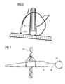
- FIG 4 shows one example for this purpose.
- a wind turbine blade BL is lifted as a first component and in a horizontal orientation by a crane CR.
- the crane CR approaches the horizontal blade BL towards the hub HB of a wind turbine, while the hub HB is the second component.
- the blade BL might have a weight of several tons and might show a typical diameter of more than 2 meters at its root end RE.
- the hub HB might be located at a height of 100 meters and might be connected to a nacelle of the wind turbine.
- the hub might show a diameter of more than 4 meters and a weight of several tons.
- the hub HB as well as the root end RE of the blade BL comprises a flange.
- the flanges might be ring-shaped for example.
- the flanges will be finally connected by threaded bolts and nuts, while a number of bolts will be used as alignment-bolts to guide the blade, when it is moved towards the hub for its final connection there.
- the blade will be approached step by step to the hub by the crane CR while the prolonged bolts are used as guiding means.
- Service personal ensure that the prolonged bolts, being pre-mounted at the flange of the blade, finally slip in allocated holes of the flange of the hub.
- the allocated holes are shaped in an adverse manner in reference to the bolts.
- the holes receive the prolonged bolts.
- a set of additional bolts which are shorter than the prolonged bolts, are used for the final fixation and connection of the components.
- a first component and a second component are aligned.
- the first component comprises guiding means and the second component comprises guiding means, while these guiding means are prepared and arranged to interact with each other.
- the guiding means of the components are prepared and arranged to align the components to each other while the components are moved towards each other for their final connection.
- the guiding means of the first component comprises an optical camera system, which is used to monitor the change of the position of the guiding means of the second component in reference to the position of the guiding means of the first component.
- the optical camera system is connected with a remote display enabling working personnel to direct the movement of the components based on the monitored position changes.
- the guiding means are adverse to each other.
- the guiding means of the first component protrudes from a joint face of the first component and projects into a joint surface of the second component.
- the guiding means of the first component comprises a threaded bolt or a bolt or a pin.
- the guiding means of the second component comprises a drill or a hole or a drilled hole.
- the optical camera system is integrated and placed into a drilling, which is drilled into the front face of the bolt.
- the first component comprises fixation means, which is preferably a flange
- the second component comprises fixation means, which is preferably a flange, too.
- Both flanges which are preferably ring-shaped, show drill holes for a connection of the first and the second component by threaded bolts and nuts.
- the flange of the first component comprises at least one bolt, which is used as guiding means of the first component, and the bolt comprises the optical camera system.
- the bolt which comprises the optical camera system, is longer than the bolts, which are mainly used to finally connect the first and the second component by threaded bolts and nuts.
- the first component is a blade of a wind turbine
- the second component is a hub of a wind turbine
- the optical camera system is a wireless optical camera system, thus gathered optical information like pictures are transferred in a wireless manner from the optical camera system to the display.
- the invention allows the aligning and joining of heavy and/or huge components, like the hub of a wind turbine or the blade of the wind turbine, without direct visual observation of working personnel.
- the invention allows an operator to remotely align the components during a lifting operation without direct visual confirmation.
- the video or a single picture of the video, obtained by the camera system is transferred to a screen.
- the pictures of the video can be reversed, mirrored, changed in their size to show details, or can be otherwise altered.
- the remote controlled movement of the components becomes more intuitive.
- the invention can be used for crane-based installation procedures as shown in the figures below. For that kind of installation a typical number of 100 bolts need to be aligned and connected, which is a quite high challenge for the crane operator.
- the invention allows an increase in safety in lifting or erection operations in a quite easy manner.
- the operator, doing remote-controlled component movements, is brought out of any dangerous zones.
- the invention delivers best perspective for bolt-and-hole alignments as described herein.
- the invention can be implemented and retrofitted into all current systems quite easily and in a cheap manner.
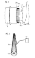
- FIG 1 shows the alignment of a first and of a second component, which is done based on the invention.
- a blade BL of a wind turbine is approached as first component C1 towards a hub HB of the wind turbine, which is the second component C2 according to the invention.
- the blade BL comprises a number of bolts BOL, which are used as guiding means GMC1 of the first component C1.
- the bolts BOL are arranged and are pre-mounted at a flange FL1 of the blade BL.
- the flange FL1 is used as fixation means FM1 of the first component C1.
- the hub HB comprises as second component C2 also a flange FL2, which is used as fixation means FM2 of the second component C2.
- the flange FL2 of the second component C2 comprises holes (not shown in detail), which are used as guiding means GMC2 of the second component C2. They interact with the bolts BOL of the flange FL1 of the first component C1, when the components C1 and C2 are moved towards each other for their final connection.
- the bolts BOL being pre-mounted at the first flange FL1, and the holes of the second flange FL2 are used for a threaded bolt-nut-connection, as soon as the components C1 and C2 are aligned and are moved towards each other into a dedicated final position for their final connection.
- FIG 1 On the bottom of the figure FIG 1 there is one prolonged bolt BOL1, which is marked with a circle. This bolt BOL1 is longer than the other bolts BOL, which are mainly used for the final connection of the components C1 and C2.
- This bolt BOL1 is also part of the guiding means GMC1 of the first component C1 and additionally comprises an optical camera system, which is explained in more detail in the next figures.
- the bolts BOL of the guiding means GMC1 of the first component C1 protrudes from a joint face of the first component C1 and projects into a joint surface of the second component C2, thus the components C1 and C2 can be aligned and moved towards in a guided manner quite easily.
- FIG 2 refers to Fig 1 and shows the bolt BOL1 in more detail.
- a front face of the bolt BOL1 comprises a drilling, in which an optical camera system OCS is located or arranged.
- the optical camera system OCS is used to monitor changes of the position of the guiding means GMC2 of the second component C2 in reference to the position of the guiding means GMC1 of the first component.
- the optical camera system OCS is connected with a remote display DIS, which is controlled by working personnel.
- the working personnel is enabled to direct the movement of the components C1 and C2 in relation to each other and based on the monitored position changes.
- the optical camera system OCS is a wireless optical camera system, thus gathered optical information like pictures are transferred in a wireless manner from the optical camera system OCS to the display DIS.
- FIG 3 shows the size and the diameter of the optical camera system OCS in reference to the diameter of the bolt BOL1.
- the optical camera system OCS shows a diameter of approximately 5 mm and a length of approximately 35 mm, while the bolt BOL1 shows a diameter of approximately 22 mm. Based on these camera dimensions it is quite easy to integrate the optical camera system OCS into the bolt BOL1.
Landscapes
- Engineering & Computer Science (AREA)
- General Engineering & Computer Science (AREA)
- Mechanical Engineering (AREA)
- Sustainable Energy (AREA)
- Chemical & Material Sciences (AREA)
- Combustion & Propulsion (AREA)
- Life Sciences & Earth Sciences (AREA)
- Sustainable Development (AREA)
- Multimedia (AREA)
- Signal Processing (AREA)
- Physics & Mathematics (AREA)
- General Physics & Mathematics (AREA)
- Accessories Of Cameras (AREA)
- Studio Devices (AREA)
- Wind Motors (AREA)
Abstract
Description
- The invention relates to a method and to an arrangement to align a first component and a second component, while they are moved towards each other for their final connection.
- It is known to use guiding means or aligning means like bolts, pins, cylinders, dove-tails or the like for the alignment of heavy and/or huge components for their connection.
- By using alignment means it is possible to move and direct components in a specific position to allow their fixation at each other finally.
-
FIG 4 shows one example for this purpose. A wind turbine blade BL is lifted as a first component and in a horizontal orientation by a crane CR. - The crane CR approaches the horizontal blade BL towards the hub HB of a wind turbine, while the hub HB is the second component.
- The blade BL might have a weight of several tons and might show a typical diameter of more than 2 meters at its root end RE.
- The hub HB might be located at a height of 100 meters and might be connected to a nacelle of the wind turbine. The hub might show a diameter of more than 4 meters and a weight of several tons.
- Typically the hub HB as well as the root end RE of the blade BL comprises a flange. The flanges might be ring-shaped for example.
- The flanges will be finally connected by threaded bolts and nuts, while a number of bolts will be used as alignment-bolts to guide the blade, when it is moved towards the hub for its final connection there.
- For the alignment movement of the blade towards the hub a number of bolts might be already positioned at one of the flanges, i.e. at the flange of the blade.
- These bolts are often prolonged in view to those bolts, which will be used to finally fix and connect the blade at the hub.
- The blade will be approached step by step to the hub by the crane CR while the prolonged bolts are used as guiding means.
- Service personal ensure that the prolonged bolts, being pre-mounted at the flange of the blade, finally slip in allocated holes of the flange of the hub.
- The allocated holes are shaped in an adverse manner in reference to the bolts. The holes receive the prolonged bolts.
- As soon as the components are in their dedicated position to each other the prolonged bolts are equipped with nuts and the components hub and blade are fixed together step by step.
- A set of additional bolts, which are shorter than the prolonged bolts, are used for the final fixation and connection of the components.
- The step-by-step movement and the alignment of the components as described above needs to be done quite carefully due to the heavy weight and due to the dimension of the components.
- Much time is spent for the controlled movement and for the alignment of the components.
Experienced working personal is needed to perform this movement, alignment and fixation work. - Thus the costs and efforts of the work will be high.
- Even the weather conditions, especially the wind speed, might limit the number of possible working-days, which are needed to fix a number of blades with the hub.
- Those limitations finally result in additional costs as operation time of the wind turbine might get lost due to bad weather conditions during the erection of the wind turbine.
- It is therefore the aim of the invention, to provide an improved method and arrangement for joining and aligning especially huge and heavy components in an easy and cheap manner.
- This aim is reached by the features of
claim 1 and by the features ofclaim 11. - Preferred configurations are object of the dependent claims.
- According to the invention a first component and a second component are aligned. The first component comprises guiding means and the second component comprises guiding means, while these guiding means are prepared and arranged to interact with each other. The guiding means of the components are prepared and arranged to align the components to each other while the components are moved towards each other for their final connection. The guiding means of the first component comprises an optical camera system, which is used to monitor the change of the position of the guiding means of the second component in reference to the position of the guiding means of the first component. The optical camera system is connected with a remote display enabling working personnel to direct the movement of the components based on the monitored position changes.
- In a preferred configuration the guiding means are adverse to each other.
- In a preferred configuration the guiding means of the first component protrudes from a joint face of the first component and projects into a joint surface of the second component.
- In a preferred configuration the guiding means of the first component comprises a threaded bolt or a bolt or a pin. The guiding means of the second component comprises a drill or a hole or a drilled hole.
- In a preferred configuration the optical camera system is integrated and placed into a drilling, which is drilled into the front face of the bolt.
- In a preferred configuration the first component comprises fixation means, which is preferably a flange, while the second component comprises fixation means, which is preferably a flange, too. Both flanges, which are preferably ring-shaped, show drill holes for a connection of the first and the second component by threaded bolts and nuts.
- In a preferred configuration the flange of the first component comprises at least one bolt, which is used as guiding means of the first component, and the bolt comprises the optical camera system.
- In a preferred configuration the bolt, which comprises the optical camera system, is longer than the bolts, which are mainly used to finally connect the first and the second component by threaded bolts and nuts.
- In a preferred configuration the first component is a blade of a wind turbine, and the second component is a hub of a wind turbine.
- In a preferred configuration the optical camera system is a wireless optical camera system, thus gathered optical information like pictures are transferred in a wireless manner from the optical camera system to the display.
- The invention allows the aligning and joining of heavy and/or huge components, like the hub of a wind turbine or the blade of the wind turbine, without direct visual observation of working personnel.
- The invention allows an operator to remotely align the components during a lifting operation without direct visual confirmation.
- There is no need for the operator to place his head between two massive components during their joining as it is done today.
- Preferably the video or a single picture of the video, obtained by the camera system, is transferred to a screen. Thus the pictures of the video can be reversed, mirrored, changed in their size to show details, or can be otherwise altered. Thus the remote controlled movement of the components becomes more intuitive.
- The invention can be used for crane-based installation procedures as shown in the figures below. For that kind of installation a typical number of 100 bolts need to be aligned and connected, which is a quite high challenge for the crane operator.
- The invention allows an increase in safety in lifting or erection operations in a quite easy manner. The operator, doing remote-controlled component movements, is brought out of any dangerous zones.
- The invention delivers best perspective for bolt-and-hole alignments as described herein.
- The invention can be implemented and retrofitted into all current systems quite easily and in a cheap manner.
- The invention is shown in more detail by figures. The figures show preferred configurations and shall not limit the scope of the idea invented.
- FIG 1
- shows the alignment of a first and of a second component, which is done based on the invention,
- FIG 2
- refers to
Fig 1 and shows one bolt in more detail, - FIG 3
- refers to
Fig 2 and shows the size of the optical camera system in reference to the bolt, and - Fig 4
- shows the joining of a wind turbine blade and a hub according to the prior art known and as described in the introduction of the description.
-
FIG 1 shows the alignment of a first and of a second component, which is done based on the invention. - A blade BL of a wind turbine is approached as first component C1 towards a hub HB of the wind turbine, which is the second component C2 according to the invention.
- The blade BL comprises a number of bolts BOL, which are used as guiding means GMC1 of the first component C1.
- The bolts BOL are arranged and are pre-mounted at a flange FL1 of the blade BL. The flange FL1 is used as fixation means FM1 of the first component C1.
- Accordingly the hub HB comprises as second component C2 also a flange FL2, which is used as fixation means FM2 of the second component C2.
- The flange FL2 of the second component C2 comprises holes (not shown in detail), which are used as guiding means GMC2 of the second component C2. They interact with the bolts BOL of the flange FL1 of the first component C1, when the components C1 and C2 are moved towards each other for their final connection.
- Thus the guiding means GMC1 and GMC2 are adverse to each other.
- The bolts BOL, being pre-mounted at the first flange FL1, and the holes of the second flange FL2 are used for a threaded bolt-nut-connection, as soon as the components C1 and C2 are aligned and are moved towards each other into a dedicated final position for their final connection.
- On the bottom of the figure
FIG 1 there is one prolonged bolt BOL1, which is marked with a circle. This bolt BOL1 is longer than the other bolts BOL, which are mainly used for the final connection of the components C1 and C2. - This bolt BOL1 is also part of the guiding means GMC1 of the first component C1 and additionally comprises an optical camera system, which is explained in more detail in the next figures.
- The bolts BOL of the guiding means GMC1 of the first component C1 protrudes from a joint face of the first component C1 and projects into a joint surface of the second component C2, thus the components C1 and C2 can be aligned and moved towards in a guided manner quite easily.
-
FIG 2 refers toFig 1 and shows the bolt BOL1 in more detail. A front face of the bolt BOL1 comprises a drilling, in which an optical camera system OCS is located or arranged. - The optical camera system OCS is used to monitor changes of the position of the guiding means GMC2 of the second component C2 in reference to the position of the guiding means GMC1 of the first component.
- The optical camera system OCS is connected with a remote display DIS, which is controlled by working personnel.
- Thus the working personnel is enabled to direct the movement of the components C1 and C2 in relation to each other and based on the monitored position changes.
- Preferably the optical camera system OCS is a wireless optical camera system, thus gathered optical information like pictures are transferred in a wireless manner from the optical camera system OCS to the display DIS.
-
FIG 3 shows the size and the diameter of the optical camera system OCS in reference to the diameter of the bolt BOL1. - The optical camera system OCS shows a diameter of approximately 5 mm and a length of approximately 35 mm, while the bolt BOL1 shows a diameter of approximately 22 mm. Based on these camera dimensions it is quite easy to integrate the optical camera system OCS into the bolt BOL1.
Claims (11)
- Arrangement to align a first component (C1) and a second component (C2),- wherein the first component (C1) comprises guiding means (GMC1) and wherein the second component (C2) comprises guiding means (CMC2), which are prepared and arranged to interact with each other,- wherein the guiding means (GMC1, GMC2) of the components (C1, C2) are prepared and arranged to align the components (C1, C2) to each other while the components (C1, C2) are moved towards each other for their final connection,
characterized in- that the guiding means (GMC1) of the first component (C1) comprises an optical camera system (OCS), which is used to monitor the change of the position of the guiding means (GMC2) of the second component (C2) in reference to the position of the guiding means (GMC1) of the first component, and- that the optical camera system (OCS) is connected with a remote display (DIS) enabling working personnel to direct the movement of the components (C1, C2) based on the monitored position changes. - Arrangement according claim 1, wherein the guiding means (GMC1, GMC2) are adverse to each other.
- Arrangement according claim 1 or claim 2, wherein the guiding means (GMC1) of the first component (C1) protrudes from a joint face of the first component (C1) and projects into a joint surface of the second component (C2).
- Arrangement according claim 3,- wherein the guiding means (GMC1) of the first component (C1) comprises a threaded bolt or a bolt or a pin, and- wherein the guiding means (GMC2) of the second component (C2) comprises a drill or a hole or a drilled hole.
- Arrangement according to claim 4, wherein the optical camera system (OCS) is integrated into a drilling, which is drilled into the front face of the bolt.
- Arrangement according to one of the previous claims,- wherein the first component (C1) comprises fixation means (FM1), which is preferably a flange,- wherein the second component (C2) comprises fixation means (FM2), which is preferably a flange, and- wherein both flanges, which are preferably ring-shaped, show drill holes for a connection of the first and the second component (C1, C2) by threaded bolts and nuts.
- Arrangement according claim 6,- wherein the flange of the first component comprises at least one bolt (GMC1), which is used as guiding means (GMC1) of the first component (C1), and- wherein the bolt comprises the optical camera system.
- Arrangement according claim 7, wherein the bolt (GMC1), which comprises the optical camera system (OCS), is longer than the bolts, which are used to finally connect the first and the second component (C1, C2) by threaded bolts and nuts.
- Arrangement according to one of the previous claims,- wherein the first component (C1) is a blade of a wind turbine, and- wherein the second component (C2) is a hub of a wind turbine.
- Arrangement according to one of the previous claims,
wherein the optical camera system (OCS) is a wireless optical camera system, thus gathered optical information like pictures are transferred in a wireless manner from the optical camera system (OCS) to the display (DIS). - Method to align a first component (C1) and a second component (C2), while they are moved towards each other for their final connection,- wherein guiding means (GMC1) of the first component (C1) interact with guiding means (CMC2) of the second component (C2),- wherein the guiding means (GMC1, GMC2) of the components (C1, C2) align the components (C1, C2) to each other while the components (C1, C2) are moved towards each other for their final connection,
characterized in- that an optical camera system (OCS), which is part of the guiding means (GMC1) of the first component (C1), is used to monitor the change of the position of the guiding means (GMC2) of the second component (C2) in reference to the position of the guiding means (GMC1) of the first component, and- the working personnel uses a remote display (DIS), which is connected with the optical camera system (OCS), to direct the movement of the components (C1, C2) based on the monitored position changes.
Priority Applications (4)
| Application Number | Priority Date | Filing Date | Title |
|---|---|---|---|
| EP14159172.7A EP2918969B1 (en) | 2014-03-12 | 2014-03-12 | Arrangement and method to align two components of a wind turbine |
| DK14159172.7T DK2918969T3 (en) | 2014-03-12 | 2014-03-12 | Device and method for aligning two components of a wind turbine |
| US14/624,043 US20150260167A1 (en) | 2014-03-12 | 2015-02-17 | Arrangement and method to align two components |
| CN201510107992.2A CN104912751A (en) | 2014-03-12 | 2015-03-12 | Arrangement and method to align two components |
Applications Claiming Priority (1)
| Application Number | Priority Date | Filing Date | Title |
|---|---|---|---|
| EP14159172.7A EP2918969B1 (en) | 2014-03-12 | 2014-03-12 | Arrangement and method to align two components of a wind turbine |
Publications (2)
| Publication Number | Publication Date |
|---|---|
| EP2918969A1 true EP2918969A1 (en) | 2015-09-16 |
| EP2918969B1 EP2918969B1 (en) | 2018-10-24 |
Family
ID=50280161
Family Applications (1)
| Application Number | Title | Priority Date | Filing Date |
|---|---|---|---|
| EP14159172.7A Not-in-force EP2918969B1 (en) | 2014-03-12 | 2014-03-12 | Arrangement and method to align two components of a wind turbine |
Country Status (4)
| Country | Link |
|---|---|
| US (1) | US20150260167A1 (en) |
| EP (1) | EP2918969B1 (en) |
| CN (1) | CN104912751A (en) |
| DK (1) | DK2918969T3 (en) |
Cited By (2)
| Publication number | Priority date | Publication date | Assignee | Title |
|---|---|---|---|---|
| EP3163071A1 (en) * | 2015-10-29 | 2017-05-03 | ALSTOM Renewables Technologies Wind B.V. | Automatic tightening of bolts |
| WO2024100172A1 (en) | 2022-11-11 | 2024-05-16 | Itrec B.V. | Installation of a nacelle and rotor blades of a wind turbine |
Families Citing this family (5)
| Publication number | Priority date | Publication date | Assignee | Title |
|---|---|---|---|---|
| JP6967537B2 (en) * | 2016-06-29 | 2021-11-17 | ヴェスタス ウィンド システムズ エー/エス | Methods used to install equipment units in assemblies, equipment packages, and wind turbine towers |
| DK3492734T3 (en) * | 2017-12-04 | 2020-08-10 | Siemens Gamesa Renewable Energy As | Wind turbine and method of assembling a wind turbine |
| NL2032063B1 (en) | 2022-06-02 | 2023-12-14 | Delta Laboratories Holding B V | Load alignment control system and method therefor |
| DK202270648A1 (en) * | 2022-12-23 | 2024-07-02 | Enabl As | Equipment positioning system |
| WO2025043271A1 (en) * | 2023-08-28 | 2025-03-06 | Zendit PTY LTD | An improved method of installing large structures such as wind turbines |
Citations (3)
| Publication number | Priority date | Publication date | Assignee | Title |
|---|---|---|---|---|
| US6412183B1 (en) * | 1996-06-14 | 2002-07-02 | Kabushiki Kaisha Saginomiya Seisakusho | Wheel alignment measuring instrument and wheel alignment measuring |
| US20050039513A1 (en) * | 2003-08-22 | 2005-02-24 | Mario Fabris | Method and apparatus for aligning equipment in a steel mill |
| US20060033908A1 (en) * | 2004-07-21 | 2006-02-16 | The Boeing Company | Rotary borescopic optical dimensional mapping tool |
Family Cites Families (11)
| Publication number | Priority date | Publication date | Assignee | Title |
|---|---|---|---|---|
| DE19917222A1 (en) * | 1999-04-16 | 2000-11-02 | Schrauben Betzer Gmbh & Co Kg | Screw and device for handling such a screw |
| JP2002094835A (en) * | 2000-09-14 | 2002-03-29 | Fuji Photo Optical Co Ltd | Prompter device |
| US8029439B2 (en) * | 2005-01-28 | 2011-10-04 | Stryker Corporation | Disposable attachable light source unit for an endoscope |
| US20080253858A1 (en) * | 2007-04-12 | 2008-10-16 | Chih-Ching Hsieh | Screwing device with function of twisting force measurement |
| US8581985B2 (en) * | 2008-11-10 | 2013-11-12 | Invue Security Products Inc. | Merchandise security system including display stand having video camera |
| ES2564260T3 (en) * | 2010-11-18 | 2016-03-21 | Vestas Wind Systems A/S | Method to handle a wind turbine blade without crane by means of a turbine bushing |
| TWI409390B (en) * | 2011-01-19 | 2013-09-21 | Kabo Tool Co | Screw having stress sensing device |
| EP2490017A1 (en) * | 2011-02-18 | 2012-08-22 | AMG Intellifast GmbH | Ultrasound measurement system |
| JP5163773B2 (en) * | 2011-05-12 | 2013-03-13 | 日産自動車株式会社 | Quality control method and quality control gauge and quality control gauge set for screw parts |
| WO2013042250A1 (en) * | 2011-09-22 | 2013-03-28 | 三菱重工業株式会社 | Rotor-blade attachment method for renewable energy power generation device |
| ES2829963T3 (en) * | 2012-06-04 | 2021-06-02 | Nordex Energy Spain Sau | System and method of assembly and disassembly of components of a wind turbine |
-
2014
- 2014-03-12 EP EP14159172.7A patent/EP2918969B1/en not_active Not-in-force
- 2014-03-12 DK DK14159172.7T patent/DK2918969T3/en active
-
2015
- 2015-02-17 US US14/624,043 patent/US20150260167A1/en not_active Abandoned
- 2015-03-12 CN CN201510107992.2A patent/CN104912751A/en active Pending
Patent Citations (3)
| Publication number | Priority date | Publication date | Assignee | Title |
|---|---|---|---|---|
| US6412183B1 (en) * | 1996-06-14 | 2002-07-02 | Kabushiki Kaisha Saginomiya Seisakusho | Wheel alignment measuring instrument and wheel alignment measuring |
| US20050039513A1 (en) * | 2003-08-22 | 2005-02-24 | Mario Fabris | Method and apparatus for aligning equipment in a steel mill |
| US20060033908A1 (en) * | 2004-07-21 | 2006-02-16 | The Boeing Company | Rotary borescopic optical dimensional mapping tool |
Cited By (3)
| Publication number | Priority date | Publication date | Assignee | Title |
|---|---|---|---|---|
| EP3163071A1 (en) * | 2015-10-29 | 2017-05-03 | ALSTOM Renewables Technologies Wind B.V. | Automatic tightening of bolts |
| WO2024100172A1 (en) | 2022-11-11 | 2024-05-16 | Itrec B.V. | Installation of a nacelle and rotor blades of a wind turbine |
| NL2033513B1 (en) | 2022-11-11 | 2024-05-28 | Itrec Bv | Installation of a nacelle and rotor blades of a wind turbine |
Also Published As
| Publication number | Publication date |
|---|---|
| EP2918969B1 (en) | 2018-10-24 |
| DK2918969T3 (en) | 2019-01-28 |
| CN104912751A (en) | 2015-09-16 |
| US20150260167A1 (en) | 2015-09-17 |
Similar Documents
| Publication | Publication Date | Title |
|---|---|---|
| EP2918969B1 (en) | Arrangement and method to align two components of a wind turbine | |
| US10704535B2 (en) | Method and assembly for aligning wind turbine structural parts | |
| EP2998569B1 (en) | Arrangement to align a part of a wind turbine | |
| EP2816224B1 (en) | Assembly method for a main rotor shaft and an installation tool thereto | |
| EP2770199A2 (en) | Tower assembly system for wind turbines and method thereof | |
| EP2982862B1 (en) | Method and device for blade replacement in wind turbines | |
| WO2010136026A2 (en) | Device for inspection and maintenance work on rotor blades and/or the tower surface of large wind power plants, particularly off-shore plants | |
| US10781560B2 (en) | Railway fastener removal system | |
| EP2998570B1 (en) | Arrangement to align a part of a wind turbine | |
| CN115448140B (en) | Lifting device, lifting system and lifting method suitable for lifting tower column segments | |
| EP3715630B1 (en) | A system and method for the service and exchange of a yaw bearing for a machine head of a wind turbine | |
| EP1957748B1 (en) | Method and device for positioning a power tong at a pipe joint | |
| CN205349256U (en) | Drilling platform well head work robot | |
| DE202010011085U1 (en) | Device for monitoring the stability of wind turbines | |
| EP3478964B1 (en) | An assembly, an installation package and a method for use in installation of an installation unit in a wind turbine tower | |
| DE8528104U1 (en) | Device for a drilling rig | |
| CN101624870B (en) | Movable adjustable operation frame | |
| DE102005053782A1 (en) | Self-climbing structure, for inspection and maintenance and repair at smooth masts, has a platform frame and a climbing frame with alternating movements between them to climb up the mast | |
| CN115263275A (en) | Method for acquiring data of fish falling in well repairing operation | |
| CN104649160A (en) | Monitoring system for maintenance and servicing of jib gantry crane | |
| CN112049587B (en) | Machine vision system and control method for drill tool joint | |
| DE102004007504B4 (en) | Hoist, in particular chain hoist or cable pull | |
| DE102020110406A1 (en) | Mobile stud pulling device | |
| CN214836109U (en) | Seven-axis correction and alignment device | |
| CN211198409U (en) | Unmanned tower crane device of multistation operation |
Legal Events
| Date | Code | Title | Description |
|---|---|---|---|
| PUAI | Public reference made under article 153(3) epc to a published international application that has entered the european phase |
Free format text: ORIGINAL CODE: 0009012 |
|
| AK | Designated contracting states |
Kind code of ref document: A1 Designated state(s): AL AT BE BG CH CY CZ DE DK EE ES FI FR GB GR HR HU IE IS IT LI LT LU LV MC MK MT NL NO PL PT RO RS SE SI SK SM TR |
|
| AX | Request for extension of the european patent |
Extension state: BA ME |
|
| 17P | Request for examination filed |
Effective date: 20150820 |
|
| RBV | Designated contracting states (corrected) |
Designated state(s): AL AT BE BG CH CY CZ DE DK EE ES FI FR GB GR HR HU IE IS IT LI LT LU LV MC MK MT NL NO PL PT RO RS SE SI SK SM TR |
|
| RAP1 | Party data changed (applicant data changed or rights of an application transferred) |
Owner name: SIEMENS AKTIENGESELLSCHAFT |
|
| GRAP | Despatch of communication of intention to grant a patent |
Free format text: ORIGINAL CODE: EPIDOSNIGR1 |
|
| STAA | Information on the status of an ep patent application or granted ep patent |
Free format text: STATUS: GRANT OF PATENT IS INTENDED |
|
| INTG | Intention to grant announced |
Effective date: 20180514 |
|
| GRAS | Grant fee paid |
Free format text: ORIGINAL CODE: EPIDOSNIGR3 |
|
| GRAA | (expected) grant |
Free format text: ORIGINAL CODE: 0009210 |
|
| STAA | Information on the status of an ep patent application or granted ep patent |
Free format text: STATUS: THE PATENT HAS BEEN GRANTED |
|
| AK | Designated contracting states |
Kind code of ref document: B1 Designated state(s): AL AT BE BG CH CY CZ DE DK EE ES FI FR GB GR HR HU IE IS IT LI LT LU LV MC MK MT NL NO PL PT RO RS SE SI SK SM TR |
|
| REG | Reference to a national code |
Ref country code: CH Ref legal event code: EP |
|
| REG | Reference to a national code |
Ref country code: IE Ref legal event code: FG4D |
|
| REG | Reference to a national code |
Ref country code: AT Ref legal event code: REF Ref document number: 1057219 Country of ref document: AT Kind code of ref document: T Effective date: 20181115 |
|
| REG | Reference to a national code |
Ref country code: DE Ref legal event code: R096 Ref document number: 602014034501 Country of ref document: DE |
|
| REG | Reference to a national code |
Ref country code: DK Ref legal event code: T3 Effective date: 20190123 |
|
| REG | Reference to a national code |
Ref country code: NL Ref legal event code: MP Effective date: 20181024 |
|
| REG | Reference to a national code |
Ref country code: LT Ref legal event code: MG4D |
|
| REG | Reference to a national code |
Ref country code: AT Ref legal event code: MK05 Ref document number: 1057219 Country of ref document: AT Kind code of ref document: T Effective date: 20181024 |
|
| PG25 | Lapsed in a contracting state [announced via postgrant information from national office to epo] |
Ref country code: NL Free format text: LAPSE BECAUSE OF FAILURE TO SUBMIT A TRANSLATION OF THE DESCRIPTION OR TO PAY THE FEE WITHIN THE PRESCRIBED TIME-LIMIT Effective date: 20181024 |
|
| PG25 | Lapsed in a contracting state [announced via postgrant information from national office to epo] |
Ref country code: IS Free format text: LAPSE BECAUSE OF FAILURE TO SUBMIT A TRANSLATION OF THE DESCRIPTION OR TO PAY THE FEE WITHIN THE PRESCRIBED TIME-LIMIT Effective date: 20190224 Ref country code: FI Free format text: LAPSE BECAUSE OF FAILURE TO SUBMIT A TRANSLATION OF THE DESCRIPTION OR TO PAY THE FEE WITHIN THE PRESCRIBED TIME-LIMIT Effective date: 20181024 Ref country code: LV Free format text: LAPSE BECAUSE OF FAILURE TO SUBMIT A TRANSLATION OF THE DESCRIPTION OR TO PAY THE FEE WITHIN THE PRESCRIBED TIME-LIMIT Effective date: 20181024 Ref country code: HR Free format text: LAPSE BECAUSE OF FAILURE TO SUBMIT A TRANSLATION OF THE DESCRIPTION OR TO PAY THE FEE WITHIN THE PRESCRIBED TIME-LIMIT Effective date: 20181024 Ref country code: AT Free format text: LAPSE BECAUSE OF FAILURE TO SUBMIT A TRANSLATION OF THE DESCRIPTION OR TO PAY THE FEE WITHIN THE PRESCRIBED TIME-LIMIT Effective date: 20181024 Ref country code: PL Free format text: LAPSE BECAUSE OF FAILURE TO SUBMIT A TRANSLATION OF THE DESCRIPTION OR TO PAY THE FEE WITHIN THE PRESCRIBED TIME-LIMIT Effective date: 20181024 Ref country code: NO Free format text: LAPSE BECAUSE OF FAILURE TO SUBMIT A TRANSLATION OF THE DESCRIPTION OR TO PAY THE FEE WITHIN THE PRESCRIBED TIME-LIMIT Effective date: 20190124 Ref country code: BG Free format text: LAPSE BECAUSE OF FAILURE TO SUBMIT A TRANSLATION OF THE DESCRIPTION OR TO PAY THE FEE WITHIN THE PRESCRIBED TIME-LIMIT Effective date: 20190124 Ref country code: ES Free format text: LAPSE BECAUSE OF FAILURE TO SUBMIT A TRANSLATION OF THE DESCRIPTION OR TO PAY THE FEE WITHIN THE PRESCRIBED TIME-LIMIT Effective date: 20181024 Ref country code: LT Free format text: LAPSE BECAUSE OF FAILURE TO SUBMIT A TRANSLATION OF THE DESCRIPTION OR TO PAY THE FEE WITHIN THE PRESCRIBED TIME-LIMIT Effective date: 20181024 |
|
| REG | Reference to a national code |
Ref country code: DE Ref legal event code: R081 Ref document number: 602014034501 Country of ref document: DE Owner name: SIEMENS GAMESA RENEWABLE ENERGY A/S, DK Free format text: FORMER OWNER: SIEMENS AKTIENGESELLSCHAFT, 80333 MUENCHEN, DE |
|
| RAP2 | Party data changed (patent owner data changed or rights of a patent transferred) |
Owner name: SIEMENS GAMESA RENEWABLE ENERGY A/S |
|
| PG25 | Lapsed in a contracting state [announced via postgrant information from national office to epo] |
Ref country code: PT Free format text: LAPSE BECAUSE OF FAILURE TO SUBMIT A TRANSLATION OF THE DESCRIPTION OR TO PAY THE FEE WITHIN THE PRESCRIBED TIME-LIMIT Effective date: 20190224 Ref country code: GR Free format text: LAPSE BECAUSE OF FAILURE TO SUBMIT A TRANSLATION OF THE DESCRIPTION OR TO PAY THE FEE WITHIN THE PRESCRIBED TIME-LIMIT Effective date: 20190125 Ref country code: SE Free format text: LAPSE BECAUSE OF FAILURE TO SUBMIT A TRANSLATION OF THE DESCRIPTION OR TO PAY THE FEE WITHIN THE PRESCRIBED TIME-LIMIT Effective date: 20181024 Ref country code: RS Free format text: LAPSE BECAUSE OF FAILURE TO SUBMIT A TRANSLATION OF THE DESCRIPTION OR TO PAY THE FEE WITHIN THE PRESCRIBED TIME-LIMIT Effective date: 20181024 Ref country code: AL Free format text: LAPSE BECAUSE OF FAILURE TO SUBMIT A TRANSLATION OF THE DESCRIPTION OR TO PAY THE FEE WITHIN THE PRESCRIBED TIME-LIMIT Effective date: 20181024 |
|
| REG | Reference to a national code |
Ref country code: DE Ref legal event code: R097 Ref document number: 602014034501 Country of ref document: DE |
|
| PG25 | Lapsed in a contracting state [announced via postgrant information from national office to epo] |
Ref country code: IT Free format text: LAPSE BECAUSE OF FAILURE TO SUBMIT A TRANSLATION OF THE DESCRIPTION OR TO PAY THE FEE WITHIN THE PRESCRIBED TIME-LIMIT Effective date: 20181024 Ref country code: CZ Free format text: LAPSE BECAUSE OF FAILURE TO SUBMIT A TRANSLATION OF THE DESCRIPTION OR TO PAY THE FEE WITHIN THE PRESCRIBED TIME-LIMIT Effective date: 20181024 |
|
| PG25 | Lapsed in a contracting state [announced via postgrant information from national office to epo] |
Ref country code: SM Free format text: LAPSE BECAUSE OF FAILURE TO SUBMIT A TRANSLATION OF THE DESCRIPTION OR TO PAY THE FEE WITHIN THE PRESCRIBED TIME-LIMIT Effective date: 20181024 Ref country code: EE Free format text: LAPSE BECAUSE OF FAILURE TO SUBMIT A TRANSLATION OF THE DESCRIPTION OR TO PAY THE FEE WITHIN THE PRESCRIBED TIME-LIMIT Effective date: 20181024 Ref country code: RO Free format text: LAPSE BECAUSE OF FAILURE TO SUBMIT A TRANSLATION OF THE DESCRIPTION OR TO PAY THE FEE WITHIN THE PRESCRIBED TIME-LIMIT Effective date: 20181024 Ref country code: SK Free format text: LAPSE BECAUSE OF FAILURE TO SUBMIT A TRANSLATION OF THE DESCRIPTION OR TO PAY THE FEE WITHIN THE PRESCRIBED TIME-LIMIT Effective date: 20181024 |
|
| PLBE | No opposition filed within time limit |
Free format text: ORIGINAL CODE: 0009261 |
|
| STAA | Information on the status of an ep patent application or granted ep patent |
Free format text: STATUS: NO OPPOSITION FILED WITHIN TIME LIMIT |
|
| REG | Reference to a national code |
Ref country code: GB Ref legal event code: 732E Free format text: REGISTERED BETWEEN 20190822 AND 20190828 |
|
| 26N | No opposition filed |
Effective date: 20190725 |
|
| PG25 | Lapsed in a contracting state [announced via postgrant information from national office to epo] |
Ref country code: MC Free format text: LAPSE BECAUSE OF FAILURE TO SUBMIT A TRANSLATION OF THE DESCRIPTION OR TO PAY THE FEE WITHIN THE PRESCRIBED TIME-LIMIT Effective date: 20181024 Ref country code: SI Free format text: LAPSE BECAUSE OF FAILURE TO SUBMIT A TRANSLATION OF THE DESCRIPTION OR TO PAY THE FEE WITHIN THE PRESCRIBED TIME-LIMIT Effective date: 20181024 |
|
| REG | Reference to a national code |
Ref country code: CH Ref legal event code: PL |
|
| PG25 | Lapsed in a contracting state [announced via postgrant information from national office to epo] |
Ref country code: LU Free format text: LAPSE BECAUSE OF NON-PAYMENT OF DUE FEES Effective date: 20190312 |
|
| REG | Reference to a national code |
Ref country code: BE Ref legal event code: MM Effective date: 20190331 |
|
| PG25 | Lapsed in a contracting state [announced via postgrant information from national office to epo] |
Ref country code: IE Free format text: LAPSE BECAUSE OF NON-PAYMENT OF DUE FEES Effective date: 20190312 Ref country code: LI Free format text: LAPSE BECAUSE OF NON-PAYMENT OF DUE FEES Effective date: 20190331 Ref country code: CH Free format text: LAPSE BECAUSE OF NON-PAYMENT OF DUE FEES Effective date: 20190331 |
|
| PG25 | Lapsed in a contracting state [announced via postgrant information from national office to epo] |
Ref country code: BE Free format text: LAPSE BECAUSE OF NON-PAYMENT OF DUE FEES Effective date: 20190331 |
|
| PG25 | Lapsed in a contracting state [announced via postgrant information from national office to epo] |
Ref country code: TR Free format text: LAPSE BECAUSE OF FAILURE TO SUBMIT A TRANSLATION OF THE DESCRIPTION OR TO PAY THE FEE WITHIN THE PRESCRIBED TIME-LIMIT Effective date: 20181024 |
|
| PGFP | Annual fee paid to national office [announced via postgrant information from national office to epo] |
Ref country code: DK Payment date: 20200324 Year of fee payment: 7 Ref country code: GB Payment date: 20200311 Year of fee payment: 7 |
|
| PG25 | Lapsed in a contracting state [announced via postgrant information from national office to epo] |
Ref country code: MT Free format text: LAPSE BECAUSE OF NON-PAYMENT OF DUE FEES Effective date: 20190312 |
|
| PGFP | Annual fee paid to national office [announced via postgrant information from national office to epo] |
Ref country code: FR Payment date: 20200316 Year of fee payment: 7 |
|
| PGFP | Annual fee paid to national office [announced via postgrant information from national office to epo] |
Ref country code: DE Payment date: 20200519 Year of fee payment: 7 |
|
| PG25 | Lapsed in a contracting state [announced via postgrant information from national office to epo] |
Ref country code: CY Free format text: LAPSE BECAUSE OF FAILURE TO SUBMIT A TRANSLATION OF THE DESCRIPTION OR TO PAY THE FEE WITHIN THE PRESCRIBED TIME-LIMIT Effective date: 20181024 |
|
| PG25 | Lapsed in a contracting state [announced via postgrant information from national office to epo] |
Ref country code: HU Free format text: LAPSE BECAUSE OF FAILURE TO SUBMIT A TRANSLATION OF THE DESCRIPTION OR TO PAY THE FEE WITHIN THE PRESCRIBED TIME-LIMIT; INVALID AB INITIO Effective date: 20140312 |
|
| REG | Reference to a national code |
Ref country code: DE Ref legal event code: R119 Ref document number: 602014034501 Country of ref document: DE |
|
| REG | Reference to a national code |
Ref country code: DK Ref legal event code: EBP Effective date: 20210331 |
|
| GBPC | Gb: european patent ceased through non-payment of renewal fee |
Effective date: 20210312 |
|
| PG25 | Lapsed in a contracting state [announced via postgrant information from national office to epo] |
Ref country code: DE Free format text: LAPSE BECAUSE OF NON-PAYMENT OF DUE FEES Effective date: 20211001 Ref country code: FR Free format text: LAPSE BECAUSE OF NON-PAYMENT OF DUE FEES Effective date: 20210331 Ref country code: GB Free format text: LAPSE BECAUSE OF NON-PAYMENT OF DUE FEES Effective date: 20210312 |
|
| PG25 | Lapsed in a contracting state [announced via postgrant information from national office to epo] |
Ref country code: DK Free format text: LAPSE BECAUSE OF NON-PAYMENT OF DUE FEES Effective date: 20210331 |
|
| PG25 | Lapsed in a contracting state [announced via postgrant information from national office to epo] |
Ref country code: MK Free format text: LAPSE BECAUSE OF FAILURE TO SUBMIT A TRANSLATION OF THE DESCRIPTION OR TO PAY THE FEE WITHIN THE PRESCRIBED TIME-LIMIT Effective date: 20181024 |