EP2918771A1 - Hose release device, rock drilling unit and method of managing hoses - Google Patents
Hose release device, rock drilling unit and method of managing hoses Download PDFInfo
- Publication number
- EP2918771A1 EP2918771A1 EP14159157.8A EP14159157A EP2918771A1 EP 2918771 A1 EP2918771 A1 EP 2918771A1 EP 14159157 A EP14159157 A EP 14159157A EP 2918771 A1 EP2918771 A1 EP 2918771A1
- Authority
- EP
- European Patent Office
- Prior art keywords
- hose
- release device
- pressure medium
- rock drilling
- arm
- Prior art date
- Legal status (The legal status is an assumption and is not a legal conclusion. Google has not performed a legal analysis and makes no representation as to the accuracy of the status listed.)
- Granted
Links
- 238000000034 method Methods 0.000 title claims abstract description 8
- 238000005553 drilling Methods 0.000 title claims description 44
- 239000011435 rock Substances 0.000 title claims description 37
- 230000000694 effects Effects 0.000 claims description 13
- 238000009527 percussion Methods 0.000 claims description 5
- 238000005452 bending Methods 0.000 claims description 4
- 230000003247 decreasing effect Effects 0.000 claims description 4
- 230000008859 change Effects 0.000 abstract description 2
- 230000008878 coupling Effects 0.000 description 8
- 238000010168 coupling process Methods 0.000 description 8
- 238000005859 coupling reaction Methods 0.000 description 8
- 239000000463 material Substances 0.000 description 6
- 239000012858 resilient material Substances 0.000 description 6
- 230000007246 mechanism Effects 0.000 description 5
- 239000004033 plastic Substances 0.000 description 3
- 229920003023 plastic Polymers 0.000 description 3
- 230000007423 decrease Effects 0.000 description 2
- 229920001971 elastomer Polymers 0.000 description 2
- 238000004519 manufacturing process Methods 0.000 description 2
- 230000008901 benefit Effects 0.000 description 1
- 238000005520 cutting process Methods 0.000 description 1
- 230000007547 defect Effects 0.000 description 1
- 238000011068 loading method Methods 0.000 description 1
- 239000007769 metal material Substances 0.000 description 1
- 230000004048 modification Effects 0.000 description 1
- 238000012986 modification Methods 0.000 description 1
- 229920002635 polyurethane Polymers 0.000 description 1
- 239000004814 polyurethane Substances 0.000 description 1
- 238000003825 pressing Methods 0.000 description 1
- 230000003449 preventive effect Effects 0.000 description 1
- 238000005086 pumping Methods 0.000 description 1
- 230000003578 releasing effect Effects 0.000 description 1
- 230000004044 response Effects 0.000 description 1
- 238000004904 shortening Methods 0.000 description 1
- 239000002689 soil Substances 0.000 description 1
Images

Classifications
-
- E—FIXED CONSTRUCTIONS
- E21—EARTH OR ROCK DRILLING; MINING
- E21B—EARTH OR ROCK DRILLING; OBTAINING OIL, GAS, WATER, SOLUBLE OR MELTABLE MATERIALS OR A SLURRY OF MINERALS FROM WELLS
- E21B7/00—Special methods or apparatus for drilling
- E21B7/02—Drilling rigs characterised by means for land transport with their own drive, e.g. skid mounting or wheel mounting
- E21B7/025—Rock drills, i.e. jumbo drills
-
- E—FIXED CONSTRUCTIONS
- E02—HYDRAULIC ENGINEERING; FOUNDATIONS; SOIL SHIFTING
- E02F—DREDGING; SOIL-SHIFTING
- E02F9/00—Component parts of dredgers or soil-shifting machines, not restricted to one of the kinds covered by groups E02F3/00 - E02F7/00
- E02F9/20—Drives; Control devices
- E02F9/22—Hydraulic or pneumatic drives
- E02F9/2264—Arrangements or adaptations of elements for hydraulic drives
- E02F9/2275—Hoses and supports therefor and protection therefor
-
- F—MECHANICAL ENGINEERING; LIGHTING; HEATING; WEAPONS; BLASTING
- F16—ENGINEERING ELEMENTS AND UNITS; GENERAL MEASURES FOR PRODUCING AND MAINTAINING EFFECTIVE FUNCTIONING OF MACHINES OR INSTALLATIONS; THERMAL INSULATION IN GENERAL
- F16L—PIPES; JOINTS OR FITTINGS FOR PIPES; SUPPORTS FOR PIPES, CABLES OR PROTECTIVE TUBING; MEANS FOR THERMAL INSULATION IN GENERAL
- F16L3/00—Supports for pipes, cables or protective tubing, e.g. hangers, holders, clamps, cleats, clips, brackets
- F16L3/01—Supports for pipes, cables or protective tubing, e.g. hangers, holders, clamps, cleats, clips, brackets for supporting or guiding the pipes, cables or protective tubing, between relatively movable points, e.g. movable channels
Definitions
- the invention relates to a hose release device for supporting one or more pressure medium hoses.
- the invention further relates to a hose arrangement, a rock drilling unit and a method of managing pressure medium hoses.
- rock drilling units are used for drilling bore holes into rock surfaces and soil.
- the rock drilling unit comprises a feed beam and a rock drilling machine arranged movably on it.
- the rock drilling machine comprises hydraulic actuators such as a rotating device and a percussion device. Hydraulic power is conveyed to the hydraulic actuators by means of hydraulic hoses, which are supported by means of guide rolls or corresponding support means.
- the present supports means are not sufficient and have some defects.
- An object of the invention is to provide a novel and improved hose release device.
- a further object is to provide a novel and improved arrangement, rock drilling unit and method, which take release of hoses into account.
- the hose release device is characterized in that the hose release device comprises: at least one support surface for supporting at least one pressure medium hose, and the at least one support surface has an initial position and a movement range allowing movement away from the initial position; at least one force member generating a support force for maintaining the support surface in the initial position; and wherein the support surface is allowed to be moved away from the initial position when a force is directed to the support surface from the at least one hose.
- the hose arrangement according to the invention is characterized in that the arrangement comprises at least one pressure medium hose arranged between a first fastening point and second fastening point; the hose is led around at least one guide roll; at least one hose release device in accordance with claims 1 to 7 is located between the first fastening point and the guide roll; and the hose release device deflects in the initial position the hose in transverse direction from a shortest line between the first fastening point and the guide roll.
- the rock drilling unit according to the invention is characterized in that at least one hose release device in accordance with claims 1 to 7 is located between at least one of the hose clamps and the guide roll; and the hose release device deflects in the initial position the hydraulic hose in transverse direction from a shortest line between the hose clamp and the guide roll.
- the method according to the invention is characterized by implementing at least one hose release; deflecting the at least one pressure medium hose from a shortest straight between the supporting objects by means of the at least hose release device; and allowing the hose to move towards the straight line when the hose is pressurized and its length is decreased due to the pressurization.
- the hose release device comprises at least one support surface for supporting the pressure medium hose.
- the support surface has an initial position and it may move away from the initial position when a force is directed to the support surface from the hose.
- the hose release device also comprises one or more force members for generating a support force for maintaining the support surface in the initial position.
- the hose release device may serve as a preventive component in a pressure medium system.
- the hose release device may decrease the tensioning force by moving the support surface. Thanks to the releasing effect damages to the supported hose may be prevented. Furthermore, extensive loadings directed to other components of the pressure medium system and guide elements of the hoses may be avoided.
- the hose release device is a protecting device dedicated to allow length compensation when length of the supported pressure medium hose is shortened due expansion of an outer diameter of the hose caused by high pressure prevailing inside the hose.
- the hose release device is utilized in a pressure medium system for supporting one or more working pressure hoses.
- the working pressure hoses are utilized for transferring needed working energy and force to a pressure medium actuator.
- In the working pressure hoses may exist high pressures.
- the hose release device is utilized in a hydraulic system for supporting one or more hydraulic hoses.
- the solution disclosed in this patent application is particularly advantageous in hydraulic systems since greater pressures and expansions exist in hydraulic hoses. However, in some cases a need for the disclosed solutions may arise also in pneumatic systems.
- the at least one force member is a spring.
- a mechanical spring is simple, durable and inexpensive component.
- the at least one force member is a leaf spring.
- the at least one force member is a coil spring.
- the at least one force member is a resilient element, which may be made of rubber or elastic plastic material, for example.
- a resilient element is polyurethane.
- the at least one force member is a resilient strap or string, which may be arranged to generate a pull force for one or more hoses in an initial position of the release device in order to deflect the hoses from their natural line.
- the at least one force member is an actuator, such as a pneumatic cylinder or bellow.
- the actuator may serve as a passive spring element, or alternatively, the actuator may be controlled by controlling feed and discharge of pressure medium.
- the support force of the force member is directed in a transverse direction relative to a longitudinal axis of the hose being supported.
- the hose release device allows the hose to be moved in the transverse direction when it is subjected to high tension load.
- the support surface or element of the release device may move in the transverse direction and may then produce transverse release effect.
- the supported one or more hoses may be deflected by means of the hose release device in an initial position, and the release device allows the hose to straighten when being tensioned.
- the hose release device is configured to deflect one or more hoses from a shortest straight line between guide rolls or corresponding supporting surfaces or objects by means of the hose release device.
- the release device will execute release function and allow the hose to move towards the shortest straight line.
- the release device may reserve hose length and may release it when needed.
- the support force of the force member is directed in a longitudinal direction of the hose being supported.
- the hose release device allows moving of the hose in the longitudinal direction.
- the movement serves as a longitudinal release effect.
- the release device may be integrated to a structure of a hose coupling.
- the release device may be a separate component arranged between two hose parts and may comprise two or more nested parts, which may slide relative to each other in the longitudinal direction.
- the release device may comprise a coupling box where the hydraulic hose is connected and which coupling box may slide longitudinally and may thus cause desired release effect.
- the hose release device is designed to affect to only one single hose.
- the hose release device comprises one support surface for supporting one hose.
- the hose release device is designed to affect to several hoses.
- the hose release device comprises several support surfaces for supporting the hoses.
- the hose release device comprises a body and one or more longitudinal arms protruding from the body.
- a distal end portion of the arm is provided with one or more connecting elements for connecting the hose to the arm.
- the distal end portion of the arm serves as a support surface for the hose.
- the longitudinal arm serves as a leaf spring and is arranged to bend relative to the body when a force is directed to it. The bending of the arm generates a release effect.
- the hose release device comprises a body and one or more longitudinal arms protruding from the body. Longitudinal axis of the arm is in an initial angle position relative to the body. When a force is directed from a hose to the arm, the arm bends and as a consequence of that the initial angle decreases. Since the arm is in the initial angular position, the arm may deflect the hose from its natural route, whereby the structure reserves hose length and releases it when needed.
- the hose release device comprises a body and one or more longitudinal arms protruding from the body. Furthermore, the hose release device has plate-like configuration.
- the plate like structure is easy to manufacture, simple, durable and inexpensive.
- the hose release device is a plate-like object comprising a body and one or more longitudinal arms protruding from the body.
- the body and the one or more arms are one integrated unity.
- the hose release device may be formed of one single plate element, whereby the structure is very simple.
- the hose release device is a plate-like object comprising a body and one or more longitudinal arms protruding from the body.
- the support force of the arm is defined by means of cross sectional dimension of the arm and a distance between the body and the connecting element.
- support properties of the arm may be affected by choosing thickness and strength of the plate material, and width and length of the arm.
- the disclosed plate-like hose release device may be formed by means of cutting and bending techniques, whereby the manufacture is cost-effective and allows easily modifications to the structure.
- a preform of the hose release device may be flame cut, plasma cut or laser cut, and the preform may be bend in a pressing machine to a desired angle.
- the hose release device is a plate-like object comprising a body and one or more longitudinal arms protruding from the body.
- the hose release device comprises several parallel arms.
- the adjacent arms may be similar.
- the adjacent arms may have different length, width and bending angle, for example, whereby they may have different release ability. Since the release device has a plate-like structure, it is relatively simple to modify the arms on case by case basis.
- the hose release device is a plate-like object comprising a body and one or more longitudinal arms protruding from the body.
- a flexible strap serving as a connecting element.
- the flexible strap may be arranged around the hose for tying the hose to the arm.
- the flexible strap may be a plastic cable tie.
- any other tying straps provided with a locking mechanism may be used.
- the hose release device is a plate-like object comprising a body and one or more longitudinal arms protruding from the body. At a distal end portion of the arm is a guiding element for keeping the arm and the hose aligned.
- the hose release device is arranged in connection with a hose clamping device.
- the hose clamping device is designed to fasten the one or more hoses to an object. The embodiments simplifies the structure since same fastening elements may be used for the hose release device and the clamping device.
- the hose release device comprises one or more rolls comprising an outer periphery.
- the outer periphery of the roll serves as a support surface in the release device.
- At least one force member is arranged to keep the roll in an initial position, and the roll is allowed to be moved towards a second position when subjected to a force directed from the hose to the support force.
- the hose release device comprises one or more rolls. Outer peripheries of the rolls may serve as support surfaces for the hoses. Structure of the roll may comprise at least one portion made of resilient material, which compresses when a force greater than the support force is directed to the roll. The outer periphery of the roll may be of resilient material. Alternatively, the roll is supported to an axle and the roll comprises a ring-shaped outer portion and inner portion. The inner portion may be of resilient material, whereby it may provide the release device with the desired release effect.
- the hose release device comprises at least one tubular element through which the hose is arranged.
- the tubular element is of flexible material and has a bent initial form.
- the bent tubular element is arranged to straighten when tension force is formed to the hose.
- the straightening of the tubular element and the supported hose executes the desired release effect.
- the tubular element may be made of plastic material, rubber or it may also be metallic material.
- the hose release device comprises a slide mechanism allowing linear movement in the longitudinal direction of the hose.
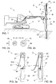
- FIG. 1 shows a rock drilling rig 1, comprising a rock drilling unit 2 which may be connected by means of a boom 3 to a movable carrier 4.
- the drilling unit 2 may comprise a feed beam 5 and a rock drilling machine 6 supported on it.
- the rock drilling machine 6 may be moved on the feed beam 5 by means of a feed device 7.
- the rock drilling machine 6 comprises a shank 8 at a front end of the rock drilling machine 6 for connecting a tool 9.
- the tool 9 may comprise one or more drill rods 10 and a drill bit 11 located at a distal end of the tool 9.
- the rock drilling machine 6 further comprises a rotating device for rotating the shank 8 and the tool 9 connected to the shank 8.
- the rock drilling machine 6 may also comprise an impact device or percussion device for generating impact pulses to the tool 9.
- one or more drill holes 12 are drilled with the drilling unit 2.
- the rock drilling machine 6 may comprise one or more hydraulic actuators.
- the percussion device and the rotation device may be hydraulic actuators.
- Hydraulic power may be generated in a hydraulic pumping unit 13, which may be located on the carrier 4.
- the hydraulic power may be transmitted by means of one or more hydraulic hoses 15 to the rock drilling machine 6. Since the rock drilling machine 6 is moved on the feed beam 5 in a drilling direction and reverse direction, the hose 14 needs to be supported to the feed beam 5 by means of a hose support system 16, which allows the movements of the rock drilling machine 6.
- the hose support system 16 may comprise a first hose clamp 17 connected to the feed beam 5 and a second hose clamp 18 arranged in connection with the rock drilling machine 6.
- the second hose clamp 18 may be arranged directly to the rock drilling machine 6 or it may arranged to a cradle 19 or any other mounting base or frame between the rock drilling machine 6 and the feed beam 5.
- the hose support system 16 may further comprise one or more guide rolls 20 arranged movably relative to the feed beam 5.
- the guide roll 20 may be located at a distal end of the feed beam 5 and may comprise a slide 21 or corresponding mechanism allowing the guide roll 20 to move in the longitudinal direction of the feed beam 5 in response to the feed movement of the rock drilling machine 6.
- the rock drilling unit 2 may be provided with one or more hose release devices disclosed above and shown in Figures 3a to 10 .
- the hose release device may be located between the first hose clamp 17 and the guide roll 20, between the guide roll 20 and the second hose clamp 18, in connection with the guide roll 20, or in connection with either of the hose clamps 17 and 18, for example.
- Figure 2a discloses a hydraulic hose 15 inside which low hydraulic pressure P1 is acting.
- An outer diameter D1 of the hydraulic hose 15 is in initial dimension.
- the outer dimension D2 expands as is shown in Figure 2b .
- Varying outer dimensions of the hydraulic hose 15 may cause changes in length of the hose 15 when the hose 15 is supported by means of the hose support system.
- the hose release device disclosed in this application provides solutions for the length change problems faced by the hydraulic hoses 15.
- FIGs 3a and 3b show a principle of a hose release device 22.
- the hose release device 22 is in an initial position, wherein a support surface of the device deflects the hydraulic hose 15 between a guide roll 20 and a second hose clamp 18 so that extra length of the hose is accumulated between them.
- the hose 15 is pressurized and the hose 15 is expanded causing length shortening. Then the hose release device 22 is bent away from the initial position and the deflecting feature is decreased or totally removed causing release affect for the hose 15. Then the hose moves towards the shortest straight line between the guide roll 20 and the second hose clamp 18.
- the hose release device 22 acts in a transverse direction relative to a longitudinal axis of the hydraulic hose 15.
- the structure of the hose release device 15 may be in accordance with Figures 4 and 5 , which are described next.
- Figure 3a discloses an alternative position for a hose release device 22e.
- the hose release device 22e may be arranged in connection with a first hose clam 17 and it operates in a similar manner as the device 22.
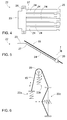
- Figure 4 discloses a hose release device 22 comprising a body 23 and several elongated arms 24 protruding from the body part. In Figure 4 there are five arms 24 but the amount of arms may be 1 to 6, for example. At a distal portion of the arm 24 may be notches 25 or other fastening portions allowing mounting of a connecting element 26, which is shown in Figure 5 . A hydraulic hose 15 may be connected to the arm 24 by means of the connecting element 26. As can be seen in Figure 5 , the structure of the release device 22 may be plate-like. Figure 5 also discloses that the arm 24 may be bent to an initial angular position relative to the body 23. A bend line 27 of the arms is shown in Figures 4 and 5 .
- Figure 4 further discloses fastening holes 28 allowing the release device 22 to be fastened by means of fastening bolts, for example.
- the fastening holes 28 may be designed so that the release device 22 may be fastened using same fastening bolts as a hose clamp.
- FIG. 6 is a simplified presentation showing basic principles of some hose release mechanisms disclosed in this application.
- a release device 22a may produce a release effect in a longitudinal direction of the hose 15.
- a release device 22b may be arranged in connection with the guide roll assembly and may also produce a longitudinal release effect.
- a release device 22c causes a deflection to the hose 15 and thus affects the hose 15 in a transverse direction.
- One single release device, or alternatively a combination of two or more release devices may be implemented.
- Figure 7a discloses a roll assembly 29 provided with several rolls 20, which may be supported by means of spring elements 30 shown in Figure 7b .
- the roll assembly may then serve as a release device 22b shown in Figure 6 .
- Figures 7c and 7d disclose rolls 20 of a hose release device 22b, wherein the rolls 20 are provided with annular sections 31 made of resilient material.
- the sections 31 made of the resilient material may compress and thereby cause desired release effect for the hose being supported by means of the rolls 20.
- Figures 8a and 8b disclose a tubular element 32, which may serve as a hose release device 22.
- a hose 15 may be arranged through the tubular element 32, which may be made of flexible material.
- the tubular element 32 is in an initial curved position and in Figure 8b the shape of the tubular element 32 has been straightened due tension forces acting in the hose 15.
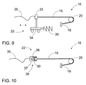
- Figure 9 discloses a hose connecting element such as a coupling box 33, which may be arranged on a slide 34 and may move in a longitudinal direction of a hose 15.
- the disclosed hose release device 22 is kept in an initial position by means of a spring element 30.
- the movable coupling box 33 may be located between two hose parts 35 and 15.
- Figure 10 discloses a separate coupling component 36 arranged between two hose parts 35 and 15.
- the component 36 is provided with two nested parts 37 and 38, which may slide relative to each other in the longitudinal direction and cause desired release effect.
- the component 36 is kept in an initial position by means of a spring element 30.
- the hose support system 16 may be in accordance with solutions shown in Figures 1, 3a and 3b and may thus comprise the disclosed guide rolls 20 and hose clamps 18.
Landscapes
- Engineering & Computer Science (AREA)
- Mining & Mineral Resources (AREA)
- Geology (AREA)
- Life Sciences & Earth Sciences (AREA)
- General Engineering & Computer Science (AREA)
- Fluid Mechanics (AREA)
- Environmental & Geological Engineering (AREA)
- Physics & Mathematics (AREA)
- General Life Sciences & Earth Sciences (AREA)
- Geochemistry & Mineralogy (AREA)
- Civil Engineering (AREA)
- Structural Engineering (AREA)
- Mechanical Engineering (AREA)
- Supports For Pipes And Cables (AREA)
- Earth Drilling (AREA)
Abstract
Description
- The invention relates to a hose release device for supporting one or more pressure medium hoses.
- The invention further relates to a hose arrangement, a rock drilling unit and a method of managing pressure medium hoses.
- The field of the invention is defined more specifically in the preambles of the independent claims.
- In mines and at other work sites, rock drilling units are used for drilling bore holes into rock surfaces and soil. The rock drilling unit comprises a feed beam and a rock drilling machine arranged movably on it. The rock drilling machine comprises hydraulic actuators such as a rotating device and a percussion device. Hydraulic power is conveyed to the hydraulic actuators by means of hydraulic hoses, which are supported by means of guide rolls or corresponding support means. However, it has been noted that the present supports means are not sufficient and have some defects.
- An object of the invention is to provide a novel and improved hose release device. A further object is to provide a novel and improved arrangement, rock drilling unit and method, which take release of hoses into account.
- The hose release device according to the invention is characterized in that the hose release device comprises: at least one support surface for supporting at least one pressure medium hose, and the at least one support surface has an initial position and a movement range allowing movement away from the initial position; at least one force member generating a support force for maintaining the support surface in the initial position; and wherein the support surface is allowed to be moved away from the initial position when a force is directed to the support surface from the at least one hose.
- The hose arrangement according to the invention is characterized in that the arrangement comprises at least one pressure medium hose arranged between a first fastening point and second fastening point; the hose is led around at least one guide roll; at least one hose release device in accordance with claims 1 to 7 is located between the first fastening point and the guide roll; and the hose release device deflects in the initial position the hose in transverse direction from a shortest line between the first fastening point and the guide roll.
- The rock drilling unit according to the invention is characterized in that at least one hose release device in accordance with claims 1 to 7 is located between at least one of the hose clamps and the guide roll; and the hose release device deflects in the initial position the hydraulic hose in transverse direction from a shortest line between the hose clamp and the guide roll.
- The method according to the invention is characterized by implementing at least one hose release; deflecting the at least one pressure medium hose from a shortest straight between the supporting objects by means of the at least hose release device; and allowing the hose to move towards the straight line when the hose is pressurized and its length is decreased due to the pressurization.
- An idea of the disclosed solution is that one or more hose release devices are arranged to support one or more hoses of a pressure medium system. The hose release device comprises at least one support surface for supporting the pressure medium hose. The support surface has an initial position and it may move away from the initial position when a force is directed to the support surface from the hose. The hose release device also comprises one or more force members for generating a support force for maintaining the support surface in the initial position.
- An advantage of the disclosed solution is that the hose release device may serve as a preventive component in a pressure medium system. When a great tensioning force is directed to the hose, then the hose release device may decrease the tensioning force by moving the support surface. Thanks to the releasing effect damages to the supported hose may be prevented. Furthermore, extensive loadings directed to other components of the pressure medium system and guide elements of the hoses may be avoided.
- According to an embodiment, the hose release device is a protecting device dedicated to allow length compensation when length of the supported pressure medium hose is shortened due expansion of an outer diameter of the hose caused by high pressure prevailing inside the hose.
- According to an embodiment, the hose release device is utilized in a pressure medium system for supporting one or more working pressure hoses. The working pressure hoses are utilized for transferring needed working energy and force to a pressure medium actuator. In the working pressure hoses may exist high pressures.
- According to an embodiment, the hose release device is utilized in a hydraulic system for supporting one or more hydraulic hoses. The solution disclosed in this patent application is particularly advantageous in hydraulic systems since greater pressures and expansions exist in hydraulic hoses. However, in some cases a need for the disclosed solutions may arise also in pneumatic systems.
- According to an embodiment, the at least one force member is a spring. A mechanical spring is simple, durable and inexpensive component.
- According to an embodiment, the at least one force member is a leaf spring.
- According to an embodiment, the at least one force member is a coil spring.
- According to an embodiment, the at least one force member is a resilient element, which may be made of rubber or elastic plastic material, for example. One possible material for the resilient element is polyurethane.
- According to an embodiment, the at least one force member is a resilient strap or string, which may be arranged to generate a pull force for one or more hoses in an initial position of the release device in order to deflect the hoses from their natural line.
- According to an embodiment, the at least one force member is an actuator, such as a pneumatic cylinder or bellow. The actuator may serve as a passive spring element, or alternatively, the actuator may be controlled by controlling feed and discharge of pressure medium.
- According to an embodiment, the support force of the force member is directed in a transverse direction relative to a longitudinal axis of the hose being supported. Thus, the hose release device allows the hose to be moved in the transverse direction when it is subjected to high tension load. The support surface or element of the release device may move in the transverse direction and may then produce transverse release effect. The supported one or more hoses may be deflected by means of the hose release device in an initial position, and the release device allows the hose to straighten when being tensioned.
- According to an embodiment, the hose release device is configured to deflect one or more hoses from a shortest straight line between guide rolls or corresponding supporting surfaces or objects by means of the hose release device. When the hose is pressurized and its length is decreased due to the pressurization, the release device will execute release function and allow the hose to move towards the shortest straight line. The release device may reserve hose length and may release it when needed.
- According to an embodiment, the support force of the force member is directed in a longitudinal direction of the hose being supported. Then the hose release device allows moving of the hose in the longitudinal direction. The movement serves as a longitudinal release effect. The release device may be integrated to a structure of a hose coupling. Alternatively, the release device may be a separate component arranged between two hose parts and may comprise two or more nested parts, which may slide relative to each other in the longitudinal direction. In an additional embodiment, the release device may comprise a coupling box where the hydraulic hose is connected and which coupling box may slide longitudinally and may thus cause desired release effect.
- According to an embodiment, the hose release device is designed to affect to only one single hose. Thus, the hose release device comprises one support surface for supporting one hose.
- According to an embodiment, the hose release device is designed to affect to several hoses. Thus, the hose release device comprises several support surfaces for supporting the hoses.
- According to an embodiment, the hose release device comprises a body and one or more longitudinal arms protruding from the body. A distal end portion of the arm is provided with one or more connecting elements for connecting the hose to the arm. The distal end portion of the arm serves as a support surface for the hose. The longitudinal arm serves as a leaf spring and is arranged to bend relative to the body when a force is directed to it. The bending of the arm generates a release effect.
- According to an embodiment, the hose release device comprises a body and one or more longitudinal arms protruding from the body. Longitudinal axis of the arm is in an initial angle position relative to the body. When a force is directed from a hose to the arm, the arm bends and as a consequence of that the initial angle decreases. Since the arm is in the initial angular position, the arm may deflect the hose from its natural route, whereby the structure reserves hose length and releases it when needed.
- According to an embodiment, the hose release device comprises a body and one or more longitudinal arms protruding from the body. Furthermore, the hose release device has plate-like configuration. The plate like structure is easy to manufacture, simple, durable and inexpensive.
- According to an embodiment, the hose release device is a plate-like object comprising a body and one or more longitudinal arms protruding from the body. The body and the one or more arms are one integrated unity. The hose release device may be formed of one single plate element, whereby the structure is very simple.
- According to an embodiment, the hose release device is a plate-like object comprising a body and one or more longitudinal arms protruding from the body. The support force of the arm is defined by means of cross sectional dimension of the arm and a distance between the body and the connecting element. Thus, support properties of the arm may be affected by choosing thickness and strength of the plate material, and width and length of the arm. The disclosed plate-like hose release device may be formed by means of cutting and bending techniques, whereby the manufacture is cost-effective and allows easily modifications to the structure. A preform of the hose release device may be flame cut, plasma cut or laser cut, and the preform may be bend in a pressing machine to a desired angle.
- According to an embodiment, the hose release device is a plate-like object comprising a body and one or more longitudinal arms protruding from the body. The hose release device comprises several parallel arms. The adjacent arms may be similar. Alternatively the adjacent arms may have different length, width and bending angle, for example, whereby they may have different release ability. Since the release device has a plate-like structure, it is relatively simple to modify the arms on case by case basis.
- According to an embodiment, the hose release device is a plate-like object comprising a body and one or more longitudinal arms protruding from the body. At a distal end portion of the arm is a flexible strap serving as a connecting element. The flexible strap may be arranged around the hose for tying the hose to the arm. At its simplest the flexible strap may be a plastic cable tie. Alternatively, any other tying straps provided with a locking mechanism may be used. This embodiment provides an easy and inexpensive, but still reliable solution for connecting the hose to the release device.
- According to an embodiment, the hose release device is a plate-like object comprising a body and one or more longitudinal arms protruding from the body. At a distal end portion of the arm is a guiding element for keeping the arm and the hose aligned.
- According to an embodiment, the hose release device is arranged in connection with a hose clamping device. The hose clamping device is designed to fasten the one or more hoses to an object. The embodiments simplifies the structure since same fastening elements may be used for the hose release device and the clamping device.
- According to an embodiment, the hose release device comprises one or more rolls comprising an outer periphery. The outer periphery of the roll serves as a support surface in the release device. At least one force member is arranged to keep the roll in an initial position, and the roll is allowed to be moved towards a second position when subjected to a force directed from the hose to the support force.
- According to an embodiment, the hose release device comprises one or more rolls. Outer peripheries of the rolls may serve as support surfaces for the hoses. Structure of the roll may comprise at least one portion made of resilient material, which compresses when a force greater than the support force is directed to the roll. The outer periphery of the roll may be of resilient material. Alternatively, the roll is supported to an axle and the roll comprises a ring-shaped outer portion and inner portion. The inner portion may be of resilient material, whereby it may provide the release device with the desired release effect.
- According to an embodiment, the hose release device comprises at least one tubular element through which the hose is arranged. The tubular element is of flexible material and has a bent initial form. The bent tubular element is arranged to straighten when tension force is formed to the hose. The straightening of the tubular element and the supported hose executes the desired release effect. The tubular element may be made of plastic material, rubber or it may also be metallic material.
- According to an embodiment, the hose release device comprises a slide mechanism allowing linear movement in the longitudinal direction of the hose.
- The above-disclosed embodiments can be combined to form desired solutions provided with necessary features disclosed.
- Some embodiments are described in more detail in the accompanying drawings, in which
-
Figure 1 is a side view of a rock drilling rig provided with a drilling unit, -
Figure 2a is a sectional view of a pressure medium hose when subjected to low pressure, andFigure 2b shows the hose when high pressure is acting inside the hose, -
Figure 3a is a schematic top view of a rock drilling unit provided with a hose release device, which is in an initial position, and inFigure 3b the same release device is in release position, -
Figure 4 is a schematic view of a hose release device provided with several arms, -
Figure 5 is a schematic view showing operation of a bendable arm of a hose release device, -
Figure 6 is a schematic view showing principles of several feasible hose release mechanisms, -
Figure 7a is a schematic view of a roll assembly provided with several rolls, -
Figure 7b is a schematic view of spring supported rolls of a roll assembly, -
Figures 7c and 7d are schematic views of rolls of a hose release device, wherein the rolls are provided with annular sections made of resilient material, -
Figures 8a and 8b are schematic views of a tubular hose release device through which the hose is arranged, -
Figure 9 is a schematic view of a hose connecting element such as a coupling box, which may slide in a longitudinal direction of the hose, and -
Figure 10 is a schematic view of a separate coupling component arranged between two hose parts and is provided with two nested parts, which may slide relative to each other in the longitudinal direction and cause desired release effect. - For the sake of clarity, the Figures show some embodiments of the disclosed solution in a simplified manner. In the Figures, like reference numerals identify like elements.
-
Figure 1 shows a rock drilling rig 1, comprising arock drilling unit 2 which may be connected by means of aboom 3 to amovable carrier 4. Thedrilling unit 2 may comprise afeed beam 5 and arock drilling machine 6 supported on it. Therock drilling machine 6 may be moved on thefeed beam 5 by means of afeed device 7. Therock drilling machine 6 comprises ashank 8 at a front end of therock drilling machine 6 for connecting a tool 9. The tool 9 may comprise one ormore drill rods 10 and adrill bit 11 located at a distal end of the tool 9. Therock drilling machine 6 further comprises a rotating device for rotating theshank 8 and the tool 9 connected to theshank 8. When the rock drilling is based on rotation R and feed of the tool then the drilling is known as rotary drilling. However, therock drilling machine 6 may also comprise an impact device or percussion device for generating impact pulses to the tool 9. At a drilling site, one or more drill holes 12 are drilled with thedrilling unit 2. - The
rock drilling machine 6 may comprise one or more hydraulic actuators. The percussion device and the rotation device may be hydraulic actuators. Hydraulic power may be generated in ahydraulic pumping unit 13, which may be located on thecarrier 4. The hydraulic power may be transmitted by means of one or morehydraulic hoses 15 to therock drilling machine 6. Since therock drilling machine 6 is moved on thefeed beam 5 in a drilling direction and reverse direction, thehose 14 needs to be supported to thefeed beam 5 by means of ahose support system 16, which allows the movements of therock drilling machine 6. Thehose support system 16 may comprise afirst hose clamp 17 connected to thefeed beam 5 and asecond hose clamp 18 arranged in connection with therock drilling machine 6. Thesecond hose clamp 18 may be arranged directly to therock drilling machine 6 or it may arranged to acradle 19 or any other mounting base or frame between therock drilling machine 6 and thefeed beam 5. Thehose support system 16 may further comprise one or more guide rolls 20 arranged movably relative to thefeed beam 5. Theguide roll 20 may be located at a distal end of thefeed beam 5 and may comprise aslide 21 or corresponding mechanism allowing theguide roll 20 to move in the longitudinal direction of thefeed beam 5 in response to the feed movement of therock drilling machine 6. Therock drilling unit 2 may be provided with one or more hose release devices disclosed above and shown inFigures 3a to 10 . The hose release device may be located between thefirst hose clamp 17 and theguide roll 20, between theguide roll 20 and thesecond hose clamp 18, in connection with theguide roll 20, or in connection with either of the hose clamps 17 and 18, for example. -
Figure 2a discloses ahydraulic hose 15 inside which low hydraulic pressure P1 is acting. An outer diameter D1 of thehydraulic hose 15 is in initial dimension. When thehydraulic hose 15 is pressurized with high hydraulic pressure P2, the outer dimension D2 expands as is shown inFigure 2b . Varying outer dimensions of thehydraulic hose 15 may cause changes in length of thehose 15 when thehose 15 is supported by means of the hose support system. The hose release device disclosed in this application provides solutions for the length change problems faced by thehydraulic hoses 15. -
Figures 3a and 3b show a principle of ahose release device 22. InFigure 3a thehose release device 22 is in an initial position, wherein a support surface of the device deflects thehydraulic hose 15 between aguide roll 20 and asecond hose clamp 18 so that extra length of the hose is accumulated between them. InFigure 3b thehose 15 is pressurized and thehose 15 is expanded causing length shortening. Then thehose release device 22 is bent away from the initial position and the deflecting feature is decreased or totally removed causing release affect for thehose 15. Then the hose moves towards the shortest straight line between theguide roll 20 and thesecond hose clamp 18. InFigures 3a and 3b thehose release device 22 acts in a transverse direction relative to a longitudinal axis of thehydraulic hose 15. The structure of thehose release device 15 may be in accordance withFigures 4 and 5 , which are described next. -
Figure 3a discloses an alternative position for ahose release device 22e. Thehose release device 22e may be arranged in connection with afirst hose clam 17 and it operates in a similar manner as thedevice 22. -
Figure 4 discloses ahose release device 22 comprising abody 23 and severalelongated arms 24 protruding from the body part. InFigure 4 there are fivearms 24 but the amount of arms may be 1 to 6, for example. At a distal portion of thearm 24 may benotches 25 or other fastening portions allowing mounting of a connectingelement 26, which is shown inFigure 5 . Ahydraulic hose 15 may be connected to thearm 24 by means of the connectingelement 26. As can be seen inFigure 5 , the structure of therelease device 22 may be plate-like.Figure 5 also discloses that thearm 24 may be bent to an initial angular position relative to thebody 23. Abend line 27 of the arms is shown inFigures 4 and 5 . When thehose 15 is pressurized with high pressure, thearm 24 may bend B away from the initial position.Figure 4 further discloses fastening holes 28 allowing therelease device 22 to be fastened by means of fastening bolts, for example. The fastening holes 28 may be designed so that therelease device 22 may be fastened using same fastening bolts as a hose clamp. -
Figure 6 is a simplified presentation showing basic principles of some hose release mechanisms disclosed in this application. Arelease device 22a may produce a release effect in a longitudinal direction of thehose 15. Arelease device 22b may be arranged in connection with the guide roll assembly and may also produce a longitudinal release effect. Arelease device 22c causes a deflection to thehose 15 and thus affects thehose 15 in a transverse direction. One single release device, or alternatively a combination of two or more release devices may be implemented. -
Figure 7a discloses aroll assembly 29 provided withseveral rolls 20, which may be supported by means ofspring elements 30 shown inFigure 7b . The roll assembly may then serve as arelease device 22b shown inFigure 6 . -
Figures 7c and 7d disclose rolls 20 of ahose release device 22b, wherein therolls 20 are provided withannular sections 31 made of resilient material. Thesections 31 made of the resilient material may compress and thereby cause desired release effect for the hose being supported by means of therolls 20. -
Figures 8a and 8b disclose atubular element 32, which may serve as ahose release device 22. Ahose 15 may be arranged through thetubular element 32, which may be made of flexible material. InFigure 8a thetubular element 32 is in an initial curved position and inFigure 8b the shape of thetubular element 32 has been straightened due tension forces acting in thehose 15. -
Figure 9 discloses a hose connecting element such as acoupling box 33, which may be arranged on aslide 34 and may move in a longitudinal direction of ahose 15. The disclosedhose release device 22 is kept in an initial position by means of aspring element 30. Themovable coupling box 33 may be located between twohose parts -
Figure 10 discloses aseparate coupling component 36 arranged between twohose parts component 36 is provided with two nestedparts component 36 is kept in an initial position by means of aspring element 30. - In
Figures 9 and 10 thehose support system 16 may be in accordance with solutions shown inFigures 1, 3a and 3b and may thus comprise the disclosed guide rolls 20 and hose clamps 18. - The drawings and the related description are only intended to illustrate the idea of the invention. In its details, the invention may vary within the scope of the claims.
Claims (11)
- A hose release device for a pressure medium system;
characterized in that
the hose release device (22) comprises:at least one support surface for supporting at least one pressure medium hose (15), and the at least one support surface has an initial position and a movement range allowing movement away from the initial position;at least one force member generating a support force for maintaining the support surface in the initial position;and wherein the support surface is allowed to be moved away from the initial position when a force is directed to the support surface from the at least one pressure medium hose (15). - The hose release device as claimed in claim 1, characterized in that
the hose release device (22) is a protecting device dedicated to allow length compensation when length of the supported pressure medium hose (15) is shortened due expansion of an outer diameter (D2) of the pressure medium hose (15) caused by high pressure (P2) prevailing inside the hose (15). - The hose release device as claimed in claim 1 or 2, characterized in that
the at least one force member is a spring (30). - The hose release device as claimed in any of the preceding claims 1 to 3, characterized in that
the support force of the force member is directed in a transverse direction relative a longitudinal axis of the pressure medium hose (15) being supported, whereby the hose release device (22) allows the hose (15) to be moved in the transverse direction and produces a transverse release effect. - The hose release device as claimed in any one of the preceding claims 1 to 4, characterized in that the hose release device (22) comprises:a body (23);at least one longitudinal arm (24) protruding from the body (23);at least one connecting element (26) at a distal end portion of the arm (24) for connecting the pressure medium hose (15) to the arm (24), whereby the distal end portion of the arm (24) serves as a support surface;and the longitudinal arm (24) serves as a leaf spring;and the arm (24) is arranged to bend (B) relative to the body (23), the bending (B) generating the release effect.
- The hose release device as claimed in claim 5, characterized in that
longitudinal axis of the at least one arm (24) is in an initial angle position relative to the body (23). - The hose release device as claimed in claim 5 or 6, characterized in that
the hose release device (22) has plate-like configuration. - A hose arrangement, characterized in that
the arrangement comprises at least one pressure medium hose (15) arranged between a first fastening point and second fastening point;
the hose (15) is led around at least one guide roll (20);
at least one hose release device (22) in accordance with claims 1 to 7 is located between the first fastening point and the guide roll (20);
and the hose release device (22) deflects in the initial position the hose (15) in transverse direction from a shortest line between the first fastening point and the guide roll (22). - A rock drilling unit, comprising:a feed beam (5);a rock drilling machine (6) arranged on the feed beam (5);a feed device (7) for moving the rock drilling machine (6) relative to the feed beam (5);at least one hydraulic hose (15) hydraulically connected to the rock drilling machine (6); anda hose support system (16) comprising a first hose clamp (17) mounted to the feed beam (5), a second hose clamp (18) mounted in connection with the rock drilling machine (6), and at least one guide roll (20) arranged movably at an end portion of the feed beam (5);characterized in thatat least one hose release device (22) in accordance with claims 1 to 7 is located between at least one of the hose clamps (17, 18) and the guide roll (20);and the hose release device (22) deflects in the initial position the hydraulic hose (15) in transverse direction from a shortest line between the hose clamp (17, 18) and the guide roll (20).
- The rock drilling rig as claimed in claim 9, characterized in that
the rock drilling machine (6) comprises a hydraulic percussion device; and at least one high pressure hose leading to the percussion device is supported by means of the hose release device (22) in accordance with claims 1 to 7. - A method of managing pressure medium hoses, the method comprising:leading at least one pressure medium hose (15) to a rock drilling machine (6); andsupporting the at least one hose (15) between at least two supporting objects;characterized byimplementing at least one hose release device (22);deflecting the at least one pressure medium hose (15) from a shortest straight line between the supporting objects by means of the at least hose release device (22); andallowing the hose (15) to move towards the straight line when the hose (15) is pressurized and its length is decreased due to the pressurization.
Priority Applications (7)
| Application Number | Priority Date | Filing Date | Title |
|---|---|---|---|
| EP14159157.8A EP2918771B1 (en) | 2014-03-12 | 2014-03-12 | Hose release device, rock drilling unit and method of managing hoses |
| CA2882037A CA2882037C (en) | 2014-03-12 | 2015-02-17 | Hose release device, rock drilling unit and method of managing hoses |
| AU2015201147A AU2015201147B2 (en) | 2014-03-12 | 2015-03-05 | Hose release device, rock drilling unit and method of managing hoses |
| CN201510106492.7A CN104913113B (en) | 2014-03-12 | 2015-03-11 | Flexible pipe release device, flexible pipe equipment and rock bore unit |
| US14/645,142 US10012027B2 (en) | 2014-03-12 | 2015-03-11 | Hose release device, rock drilling unit and method of managing hoses |
| ZA2015/01676A ZA201501676B (en) | 2014-03-12 | 2015-03-11 | Hose release device, rock drilling unit and method of managing hoses |
| JP2015049129A JP5941179B2 (en) | 2014-03-12 | 2015-03-12 | Hose release device, rock drilling unit and hose control method |
Applications Claiming Priority (1)
| Application Number | Priority Date | Filing Date | Title |
|---|---|---|---|
| EP14159157.8A EP2918771B1 (en) | 2014-03-12 | 2014-03-12 | Hose release device, rock drilling unit and method of managing hoses |
Publications (2)
| Publication Number | Publication Date |
|---|---|
| EP2918771A1 true EP2918771A1 (en) | 2015-09-16 |
| EP2918771B1 EP2918771B1 (en) | 2017-08-02 |
Family
ID=50289395
Family Applications (1)
| Application Number | Title | Priority Date | Filing Date |
|---|---|---|---|
| EP14159157.8A Not-in-force EP2918771B1 (en) | 2014-03-12 | 2014-03-12 | Hose release device, rock drilling unit and method of managing hoses |
Country Status (7)
| Country | Link |
|---|---|
| US (1) | US10012027B2 (en) |
| EP (1) | EP2918771B1 (en) |
| JP (1) | JP5941179B2 (en) |
| CN (1) | CN104913113B (en) |
| AU (1) | AU2015201147B2 (en) |
| CA (1) | CA2882037C (en) |
| ZA (1) | ZA201501676B (en) |
Families Citing this family (4)
| Publication number | Priority date | Publication date | Assignee | Title |
|---|---|---|---|---|
| EP2918771B1 (en) | 2014-03-12 | 2017-08-02 | Sandvik Mining and Construction Oy | Hose release device, rock drilling unit and method of managing hoses |
| CN110159855B (en) * | 2019-06-27 | 2023-12-22 | 北京三一智造科技有限公司 | Hose clamp group device and rotary drilling rig |
| CN110904796B (en) * | 2019-11-23 | 2021-09-28 | 郑州大学 | Differential settlement monitoring device and method for new and old road surfaces |
| CN115199819B (en) * | 2022-07-27 | 2023-04-25 | 湖南鹏翔星通汽车有限公司 | Automatic oil pipe adjusting device for propelling beam |
Citations (4)
| Publication number | Priority date | Publication date | Assignee | Title |
|---|---|---|---|---|
| US3776403A (en) * | 1972-06-07 | 1973-12-04 | Billings R O | Hose minder |
| US4384619A (en) * | 1980-08-18 | 1983-05-24 | J. L. Case Company | Hose tensioning device for side shift plow assembly |
| DE4007470C1 (en) * | 1990-03-09 | 1991-03-07 | O & K Orenstein & Koppel Ag, 1000 Berlin, De | Length compensator for hydraulic hose - consists of flexible section with loop between relatively hinged supports |
| US20110132862A1 (en) * | 2008-07-11 | 2011-06-09 | Eckhard Wimmer | Mobile crane with hose guide |
Family Cites Families (7)
| Publication number | Priority date | Publication date | Assignee | Title |
|---|---|---|---|---|
| JPS6022592U (en) * | 1983-07-25 | 1985-02-16 | 日立建機株式会社 | Additional type drilling tool holder device |
| JPS61142797U (en) * | 1985-02-27 | 1986-09-03 | ||
| JPH08285149A (en) * | 1995-04-11 | 1996-11-01 | Bridgestone Corp | Surge pressure allowable hose |
| JP4212665B2 (en) * | 1997-05-21 | 2009-01-21 | 横浜ゴム株式会社 | High pressure hose |
| FI20030115L (en) * | 2003-01-24 | 2004-07-25 | Sandvik Tamrock Oy | Hydraulic system for an excavation device and method for adjusting the power of a rock drilling machine |
| JP2009179118A (en) * | 2008-01-29 | 2009-08-13 | Autonetworks Technologies Ltd | Mounting structure of wire harness for feeding sliding door |
| EP2918771B1 (en) | 2014-03-12 | 2017-08-02 | Sandvik Mining and Construction Oy | Hose release device, rock drilling unit and method of managing hoses |
-
2014
- 2014-03-12 EP EP14159157.8A patent/EP2918771B1/en not_active Not-in-force
-
2015
- 2015-02-17 CA CA2882037A patent/CA2882037C/en not_active Expired - Fee Related
- 2015-03-05 AU AU2015201147A patent/AU2015201147B2/en not_active Ceased
- 2015-03-11 CN CN201510106492.7A patent/CN104913113B/en not_active Expired - Fee Related
- 2015-03-11 US US14/645,142 patent/US10012027B2/en not_active Expired - Fee Related
- 2015-03-11 ZA ZA2015/01676A patent/ZA201501676B/en unknown
- 2015-03-12 JP JP2015049129A patent/JP5941179B2/en not_active Expired - Fee Related
Patent Citations (4)
| Publication number | Priority date | Publication date | Assignee | Title |
|---|---|---|---|---|
| US3776403A (en) * | 1972-06-07 | 1973-12-04 | Billings R O | Hose minder |
| US4384619A (en) * | 1980-08-18 | 1983-05-24 | J. L. Case Company | Hose tensioning device for side shift plow assembly |
| DE4007470C1 (en) * | 1990-03-09 | 1991-03-07 | O & K Orenstein & Koppel Ag, 1000 Berlin, De | Length compensator for hydraulic hose - consists of flexible section with loop between relatively hinged supports |
| US20110132862A1 (en) * | 2008-07-11 | 2011-06-09 | Eckhard Wimmer | Mobile crane with hose guide |
Also Published As
| Publication number | Publication date |
|---|---|
| US20150260314A1 (en) | 2015-09-17 |
| CA2882037A1 (en) | 2015-09-12 |
| CN104913113B (en) | 2017-06-06 |
| CN104913113A (en) | 2015-09-16 |
| AU2015201147B2 (en) | 2016-01-28 |
| JP5941179B2 (en) | 2016-06-29 |
| CA2882037C (en) | 2017-06-27 |
| US10012027B2 (en) | 2018-07-03 |
| ZA201501676B (en) | 2016-01-27 |
| JP2015175523A (en) | 2015-10-05 |
| EP2918771B1 (en) | 2017-08-02 |
| AU2015201147A1 (en) | 2015-10-01 |
Similar Documents
| Publication | Publication Date | Title |
|---|---|---|
| EP2918771B1 (en) | Hose release device, rock drilling unit and method of managing hoses | |
| CN102278419A (en) | Pipeline guiding device having resetting unit and manipulator with the pipeline guiding device | |
| AU2003203116A1 (en) | Pneumatic actuator | |
| RU2008126783A (en) | TOOL | |
| US20170175462A1 (en) | Drill rod changer, rock drilling unit and method of changing drill rods | |
| JP2019011670A (en) | Gripping device and method for gripping a drilling tool | |
| MX2024010714A (en) | Support for drilling and bolting tool. | |
| AU2016200988B2 (en) | A mining boom and method of supporting hoses | |
| ZA202209919B (en) | Support for drilling and bolting tool | |
| EP2176492A1 (en) | Method and apparatus for drilling hole into bedrock | |
| WO1992013226A1 (en) | A tool and a process for replacement of underground ducts | |
| EP3733432B1 (en) | Towing arrangement and mine machine | |
| KR20070057700A (en) | Working device of construction machinery | |
| WO2001075233A1 (en) | Piping structure of working machine | |
| JP6190744B2 (en) | Concrete compaction device and concrete compaction method | |
| KR101329333B1 (en) | Arm for Rock drilling rod storage | |
| CN115397679B (en) | Traction-mounted and mobile work machinery | |
| KR20160010047A (en) | Guide system for boring machine | |
| US20050191134A1 (en) | Telescoping underwater guide | |
| WO2017200655A1 (en) | Skate drive and tubular clamping system for a catwalk | |
| JP7423651B2 (en) | Rock drilling equipment and rock drilling machine | |
| GB2445710A (en) | System and method for tensioning pipe sections to form a pipeline | |
| US11867007B2 (en) | Safe stab and self-aligning coiled tubing apparatus | |
| EP4008881A1 (en) | Extendable boom for mining vehicle and mining vehicle | |
| CN203500816U (en) | Flexible connection device |
Legal Events
| Date | Code | Title | Description |
|---|---|---|---|
| PUAI | Public reference made under article 153(3) epc to a published international application that has entered the european phase |
Free format text: ORIGINAL CODE: 0009012 |
|
| AK | Designated contracting states |
Kind code of ref document: A1 Designated state(s): AL AT BE BG CH CY CZ DE DK EE ES FI FR GB GR HR HU IE IS IT LI LT LU LV MC MK MT NL NO PL PT RO RS SE SI SK SM TR |
|
| AX | Request for extension of the european patent |
Extension state: BA ME |
|
| 17P | Request for examination filed |
Effective date: 20160316 |
|
| RBV | Designated contracting states (corrected) |
Designated state(s): AL AT BE BG CH CY CZ DE DK EE ES FI FR GB GR HR HU IE IS IT LI LT LU LV MC MK MT NL NO PL PT RO RS SE SI SK SM TR |
|
| RIC1 | Information provided on ipc code assigned before grant |
Ipc: E02F 9/22 20060101ALI20170220BHEP Ipc: E21B 7/02 20060101AFI20170220BHEP |
|
| GRAP | Despatch of communication of intention to grant a patent |
Free format text: ORIGINAL CODE: EPIDOSNIGR1 |
|
| INTG | Intention to grant announced |
Effective date: 20170418 |
|
| GRAS | Grant fee paid |
Free format text: ORIGINAL CODE: EPIDOSNIGR3 |
|
| GRAA | (expected) grant |
Free format text: ORIGINAL CODE: 0009210 |
|
| AK | Designated contracting states |
Kind code of ref document: B1 Designated state(s): AL AT BE BG CH CY CZ DE DK EE ES FI FR GB GR HR HU IE IS IT LI LT LU LV MC MK MT NL NO PL PT RO RS SE SI SK SM TR |
|
| REG | Reference to a national code |
Ref country code: CH Ref legal event code: EP Ref country code: AT Ref legal event code: REF Ref document number: 914686 Country of ref document: AT Kind code of ref document: T Effective date: 20170815 |
|
| REG | Reference to a national code |
Ref country code: IE Ref legal event code: FG4D |
|
| REG | Reference to a national code |
Ref country code: SE Ref legal event code: TRGR |
|
| REG | Reference to a national code |
Ref country code: DE Ref legal event code: R096 Ref document number: 602014012408 Country of ref document: DE |
|
| REG | Reference to a national code |
Ref country code: NL Ref legal event code: MP Effective date: 20170802 |
|
| REG | Reference to a national code |
Ref country code: AT Ref legal event code: MK05 Ref document number: 914686 Country of ref document: AT Kind code of ref document: T Effective date: 20170802 |
|
| REG | Reference to a national code |
Ref country code: LT Ref legal event code: MG4D |
|
| PG25 | Lapsed in a contracting state [announced via postgrant information from national office to epo] |
Ref country code: LT Free format text: LAPSE BECAUSE OF FAILURE TO SUBMIT A TRANSLATION OF THE DESCRIPTION OR TO PAY THE FEE WITHIN THE PRESCRIBED TIME-LIMIT Effective date: 20170802 Ref country code: AT Free format text: LAPSE BECAUSE OF FAILURE TO SUBMIT A TRANSLATION OF THE DESCRIPTION OR TO PAY THE FEE WITHIN THE PRESCRIBED TIME-LIMIT Effective date: 20170802 Ref country code: HR Free format text: LAPSE BECAUSE OF FAILURE TO SUBMIT A TRANSLATION OF THE DESCRIPTION OR TO PAY THE FEE WITHIN THE PRESCRIBED TIME-LIMIT Effective date: 20170802 Ref country code: NL Free format text: LAPSE BECAUSE OF FAILURE TO SUBMIT A TRANSLATION OF THE DESCRIPTION OR TO PAY THE FEE WITHIN THE PRESCRIBED TIME-LIMIT Effective date: 20170802 Ref country code: NO Free format text: LAPSE BECAUSE OF FAILURE TO SUBMIT A TRANSLATION OF THE DESCRIPTION OR TO PAY THE FEE WITHIN THE PRESCRIBED TIME-LIMIT Effective date: 20171102 |
|
| REG | Reference to a national code |
Ref country code: FR Ref legal event code: PLFP Year of fee payment: 5 |
|
| PG25 | Lapsed in a contracting state [announced via postgrant information from national office to epo] |
Ref country code: BG Free format text: LAPSE BECAUSE OF FAILURE TO SUBMIT A TRANSLATION OF THE DESCRIPTION OR TO PAY THE FEE WITHIN THE PRESCRIBED TIME-LIMIT Effective date: 20171102 Ref country code: RS Free format text: LAPSE BECAUSE OF FAILURE TO SUBMIT A TRANSLATION OF THE DESCRIPTION OR TO PAY THE FEE WITHIN THE PRESCRIBED TIME-LIMIT Effective date: 20170802 Ref country code: IS Free format text: LAPSE BECAUSE OF FAILURE TO SUBMIT A TRANSLATION OF THE DESCRIPTION OR TO PAY THE FEE WITHIN THE PRESCRIBED TIME-LIMIT Effective date: 20171202 Ref country code: GR Free format text: LAPSE BECAUSE OF FAILURE TO SUBMIT A TRANSLATION OF THE DESCRIPTION OR TO PAY THE FEE WITHIN THE PRESCRIBED TIME-LIMIT Effective date: 20171103 Ref country code: ES Free format text: LAPSE BECAUSE OF FAILURE TO SUBMIT A TRANSLATION OF THE DESCRIPTION OR TO PAY THE FEE WITHIN THE PRESCRIBED TIME-LIMIT Effective date: 20170802 Ref country code: LV Free format text: LAPSE BECAUSE OF FAILURE TO SUBMIT A TRANSLATION OF THE DESCRIPTION OR TO PAY THE FEE WITHIN THE PRESCRIBED TIME-LIMIT Effective date: 20170802 Ref country code: PL Free format text: LAPSE BECAUSE OF FAILURE TO SUBMIT A TRANSLATION OF THE DESCRIPTION OR TO PAY THE FEE WITHIN THE PRESCRIBED TIME-LIMIT Effective date: 20170802 |
|
| PG25 | Lapsed in a contracting state [announced via postgrant information from national office to epo] |
Ref country code: CZ Free format text: LAPSE BECAUSE OF FAILURE TO SUBMIT A TRANSLATION OF THE DESCRIPTION OR TO PAY THE FEE WITHIN THE PRESCRIBED TIME-LIMIT Effective date: 20170802 Ref country code: DK Free format text: LAPSE BECAUSE OF FAILURE TO SUBMIT A TRANSLATION OF THE DESCRIPTION OR TO PAY THE FEE WITHIN THE PRESCRIBED TIME-LIMIT Effective date: 20170802 Ref country code: RO Free format text: LAPSE BECAUSE OF FAILURE TO SUBMIT A TRANSLATION OF THE DESCRIPTION OR TO PAY THE FEE WITHIN THE PRESCRIBED TIME-LIMIT Effective date: 20170802 |
|
| REG | Reference to a national code |
Ref country code: DE Ref legal event code: R097 Ref document number: 602014012408 Country of ref document: DE |
|
| PG25 | Lapsed in a contracting state [announced via postgrant information from national office to epo] |
Ref country code: SK Free format text: LAPSE BECAUSE OF FAILURE TO SUBMIT A TRANSLATION OF THE DESCRIPTION OR TO PAY THE FEE WITHIN THE PRESCRIBED TIME-LIMIT Effective date: 20170802 Ref country code: IT Free format text: LAPSE BECAUSE OF FAILURE TO SUBMIT A TRANSLATION OF THE DESCRIPTION OR TO PAY THE FEE WITHIN THE PRESCRIBED TIME-LIMIT Effective date: 20170802 Ref country code: SM Free format text: LAPSE BECAUSE OF FAILURE TO SUBMIT A TRANSLATION OF THE DESCRIPTION OR TO PAY THE FEE WITHIN THE PRESCRIBED TIME-LIMIT Effective date: 20170802 Ref country code: EE Free format text: LAPSE BECAUSE OF FAILURE TO SUBMIT A TRANSLATION OF THE DESCRIPTION OR TO PAY THE FEE WITHIN THE PRESCRIBED TIME-LIMIT Effective date: 20170802 |
|
| PLBE | No opposition filed within time limit |
Free format text: ORIGINAL CODE: 0009261 |
|
| STAA | Information on the status of an ep patent application or granted ep patent |
Free format text: STATUS: NO OPPOSITION FILED WITHIN TIME LIMIT |
|
| 26N | No opposition filed |
Effective date: 20180503 |
|
| PG25 | Lapsed in a contracting state [announced via postgrant information from national office to epo] |
Ref country code: SI Free format text: LAPSE BECAUSE OF FAILURE TO SUBMIT A TRANSLATION OF THE DESCRIPTION OR TO PAY THE FEE WITHIN THE PRESCRIBED TIME-LIMIT Effective date: 20170802 |
|
| REG | Reference to a national code |
Ref country code: CH Ref legal event code: PL |
|
| GBPC | Gb: european patent ceased through non-payment of renewal fee |
Effective date: 20180312 |
|
| PG25 | Lapsed in a contracting state [announced via postgrant information from national office to epo] |
Ref country code: MC Free format text: LAPSE BECAUSE OF FAILURE TO SUBMIT A TRANSLATION OF THE DESCRIPTION OR TO PAY THE FEE WITHIN THE PRESCRIBED TIME-LIMIT Effective date: 20170802 |
|
| REG | Reference to a national code |
Ref country code: BE Ref legal event code: MM Effective date: 20180331 |
|
| REG | Reference to a national code |
Ref country code: IE Ref legal event code: MM4A |
|
| PG25 | Lapsed in a contracting state [announced via postgrant information from national office to epo] |
Ref country code: LU Free format text: LAPSE BECAUSE OF NON-PAYMENT OF DUE FEES Effective date: 20180312 |
|
| PG25 | Lapsed in a contracting state [announced via postgrant information from national office to epo] |
Ref country code: IE Free format text: LAPSE BECAUSE OF NON-PAYMENT OF DUE FEES Effective date: 20180312 |
|
| PG25 | Lapsed in a contracting state [announced via postgrant information from national office to epo] |
Ref country code: CH Free format text: LAPSE BECAUSE OF NON-PAYMENT OF DUE FEES Effective date: 20180331 Ref country code: GB Free format text: LAPSE BECAUSE OF NON-PAYMENT OF DUE FEES Effective date: 20180312 Ref country code: BE Free format text: LAPSE BECAUSE OF NON-PAYMENT OF DUE FEES Effective date: 20180331 Ref country code: LI Free format text: LAPSE BECAUSE OF NON-PAYMENT OF DUE FEES Effective date: 20180331 |
|
| PGFP | Annual fee paid to national office [announced via postgrant information from national office to epo] |
Ref country code: FI Payment date: 20190311 Year of fee payment: 6 Ref country code: DE Payment date: 20190226 Year of fee payment: 6 |
|
| PGFP | Annual fee paid to national office [announced via postgrant information from national office to epo] |
Ref country code: SE Payment date: 20190311 Year of fee payment: 6 Ref country code: FR Payment date: 20190226 Year of fee payment: 6 |
|
| PG25 | Lapsed in a contracting state [announced via postgrant information from national office to epo] |
Ref country code: MT Free format text: LAPSE BECAUSE OF NON-PAYMENT OF DUE FEES Effective date: 20180312 |
|
| PG25 | Lapsed in a contracting state [announced via postgrant information from national office to epo] |
Ref country code: TR Free format text: LAPSE BECAUSE OF FAILURE TO SUBMIT A TRANSLATION OF THE DESCRIPTION OR TO PAY THE FEE WITHIN THE PRESCRIBED TIME-LIMIT Effective date: 20170802 |
|
| PG25 | Lapsed in a contracting state [announced via postgrant information from national office to epo] |
Ref country code: PT Free format text: LAPSE BECAUSE OF FAILURE TO SUBMIT A TRANSLATION OF THE DESCRIPTION OR TO PAY THE FEE WITHIN THE PRESCRIBED TIME-LIMIT Effective date: 20170802 |
|
| PG25 | Lapsed in a contracting state [announced via postgrant information from national office to epo] |
Ref country code: CY Free format text: LAPSE BECAUSE OF FAILURE TO SUBMIT A TRANSLATION OF THE DESCRIPTION OR TO PAY THE FEE WITHIN THE PRESCRIBED TIME-LIMIT Effective date: 20170802 Ref country code: MK Free format text: LAPSE BECAUSE OF NON-PAYMENT OF DUE FEES Effective date: 20170802 Ref country code: HU Free format text: LAPSE BECAUSE OF FAILURE TO SUBMIT A TRANSLATION OF THE DESCRIPTION OR TO PAY THE FEE WITHIN THE PRESCRIBED TIME-LIMIT; INVALID AB INITIO Effective date: 20140312 |
|
| PG25 | Lapsed in a contracting state [announced via postgrant information from national office to epo] |
Ref country code: AL Free format text: LAPSE BECAUSE OF FAILURE TO SUBMIT A TRANSLATION OF THE DESCRIPTION OR TO PAY THE FEE WITHIN THE PRESCRIBED TIME-LIMIT Effective date: 20170802 |
|
| REG | Reference to a national code |
Ref country code: DE Ref legal event code: R119 Ref document number: 602014012408 Country of ref document: DE |
|
| REG | Reference to a national code |
Ref country code: FI Ref legal event code: MAE |
|
| PG25 | Lapsed in a contracting state [announced via postgrant information from national office to epo] |
Ref country code: FI Free format text: LAPSE BECAUSE OF NON-PAYMENT OF DUE FEES Effective date: 20200312 |
|
| PG25 | Lapsed in a contracting state [announced via postgrant information from national office to epo] |
Ref country code: DE Free format text: LAPSE BECAUSE OF NON-PAYMENT OF DUE FEES Effective date: 20201001 Ref country code: FR Free format text: LAPSE BECAUSE OF NON-PAYMENT OF DUE FEES Effective date: 20200331 Ref country code: SE Free format text: LAPSE BECAUSE OF NON-PAYMENT OF DUE FEES Effective date: 20200313 |