EP2918728B1 - Device for deep driving of tubes having a large diameter - Google Patents
Device for deep driving of tubes having a large diameter Download PDFInfo
- Publication number
- EP2918728B1 EP2918728B1 EP15158504.9A EP15158504A EP2918728B1 EP 2918728 B1 EP2918728 B1 EP 2918728B1 EP 15158504 A EP15158504 A EP 15158504A EP 2918728 B1 EP2918728 B1 EP 2918728B1
- Authority
- EP
- European Patent Office
- Prior art keywords
- tube
- excavation
- tubing device
- tower
- tube segment
- Prior art date
- Legal status (The legal status is an assumption and is not a legal conclusion. Google has not performed a legal analysis and makes no representation as to the accuracy of the status listed.)
- Active
Links
- 238000009412 basement excavation Methods 0.000 claims description 132
- 230000033001 locomotion Effects 0.000 claims description 25
- 238000000605 extraction Methods 0.000 claims description 18
- 238000011068 loading method Methods 0.000 claims description 12
- 238000000034 method Methods 0.000 claims description 8
- 230000036961 partial effect Effects 0.000 claims description 8
- 230000000903 blocking effect Effects 0.000 claims description 7
- 238000005266 casting Methods 0.000 claims description 7
- 238000003780 insertion Methods 0.000 claims description 7
- 230000037431 insertion Effects 0.000 claims description 7
- 230000005540 biological transmission Effects 0.000 claims description 4
- 230000008878 coupling Effects 0.000 claims description 3
- 238000010168 coupling process Methods 0.000 claims description 3
- 238000005859 coupling reaction Methods 0.000 claims description 3
- 230000002452 interceptive effect Effects 0.000 claims description 3
- 230000000295 complement effect Effects 0.000 claims description 2
- 230000003213 activating effect Effects 0.000 claims 1
- 230000000750 progressive effect Effects 0.000 claims 1
- 208000014617 hemorrhoid Diseases 0.000 description 15
- 238000013519 translation Methods 0.000 description 8
- 230000014616 translation Effects 0.000 description 8
- 239000003381 stabilizer Substances 0.000 description 7
- 230000000087 stabilizing effect Effects 0.000 description 5
- 238000005516 engineering process Methods 0.000 description 4
- 239000000203 mixture Substances 0.000 description 4
- 238000005553 drilling Methods 0.000 description 3
- 238000011049 filling Methods 0.000 description 3
- 230000002787 reinforcement Effects 0.000 description 3
- 230000000284 resting effect Effects 0.000 description 3
- 230000002441 reversible effect Effects 0.000 description 3
- 239000004568 cement Substances 0.000 description 2
- 239000011248 coating agent Substances 0.000 description 2
- 238000000576 coating method Methods 0.000 description 2
- 238000007599 discharging Methods 0.000 description 2
- 238000006073 displacement reaction Methods 0.000 description 2
- 230000000670 limiting effect Effects 0.000 description 2
- 239000007788 liquid Substances 0.000 description 2
- 239000000463 material Substances 0.000 description 2
- 238000012986 modification Methods 0.000 description 2
- 230000004048 modification Effects 0.000 description 2
- 238000005192 partition Methods 0.000 description 2
- 238000004064 recycling Methods 0.000 description 2
- 238000012546 transfer Methods 0.000 description 2
- 229910000278 bentonite Inorganic materials 0.000 description 1
- 239000000440 bentonite Substances 0.000 description 1
- SVPXDRXYRYOSEX-UHFFFAOYSA-N bentoquatam Chemical compound O.O=[Si]=O.O=[Al]O[Al]=O SVPXDRXYRYOSEX-UHFFFAOYSA-N 0.000 description 1
- 230000002301 combined effect Effects 0.000 description 1
- 238000002485 combustion reaction Methods 0.000 description 1
- 230000006835 compression Effects 0.000 description 1
- 238000007906 compression Methods 0.000 description 1
- 238000010276 construction Methods 0.000 description 1
- 230000001419 dependent effect Effects 0.000 description 1
- 238000013461 design Methods 0.000 description 1
- 239000012530 fluid Substances 0.000 description 1
- 239000000446 fuel Substances 0.000 description 1
- 239000003673 groundwater Substances 0.000 description 1
- 229920000642 polymer Polymers 0.000 description 1
- 238000011084 recovery Methods 0.000 description 1
- 230000002829 reductive effect Effects 0.000 description 1
- 238000000926 separation method Methods 0.000 description 1
- 239000000126 substance Substances 0.000 description 1
- XLYOFNOQVPJJNP-UHFFFAOYSA-N water Substances O XLYOFNOQVPJJNP-UHFFFAOYSA-N 0.000 description 1
Images

Classifications
-
- E—FIXED CONSTRUCTIONS
- E02—HYDRAULIC ENGINEERING; FOUNDATIONS; SOIL SHIFTING
- E02D—FOUNDATIONS; EXCAVATIONS; EMBANKMENTS; UNDERGROUND OR UNDERWATER STRUCTURES
- E02D5/00—Bulkheads, piles, or other structural elements specially adapted to foundation engineering
- E02D5/22—Piles
- E02D5/34—Concrete or concrete-like piles cast in position ; Apparatus for making same
- E02D5/38—Concrete or concrete-like piles cast in position ; Apparatus for making same making by use of mould-pipes or other moulds
- E02D5/385—Concrete or concrete-like piles cast in position ; Apparatus for making same making by use of mould-pipes or other moulds with removal of the outer mould-pipes
-
- E—FIXED CONSTRUCTIONS
- E02—HYDRAULIC ENGINEERING; FOUNDATIONS; SOIL SHIFTING
- E02D—FOUNDATIONS; EXCAVATIONS; EMBANKMENTS; UNDERGROUND OR UNDERWATER STRUCTURES
- E02D11/00—Methods or apparatus specially adapted for both placing and removing sheet pile bulkheads, piles, or mould-pipes
-
- E—FIXED CONSTRUCTIONS
- E02—HYDRAULIC ENGINEERING; FOUNDATIONS; SOIL SHIFTING
- E02D—FOUNDATIONS; EXCAVATIONS; EMBANKMENTS; UNDERGROUND OR UNDERWATER STRUCTURES
- E02D15/00—Handling building or like materials for hydraulic engineering or foundations
- E02D15/02—Handling of bulk concrete specially for foundation or hydraulic engineering purposes
- E02D15/04—Placing concrete in mould-pipes, pile tubes, bore-holes or narrow shafts
-
- E—FIXED CONSTRUCTIONS
- E02—HYDRAULIC ENGINEERING; FOUNDATIONS; SOIL SHIFTING
- E02D—FOUNDATIONS; EXCAVATIONS; EMBANKMENTS; UNDERGROUND OR UNDERWATER STRUCTURES
- E02D5/00—Bulkheads, piles, or other structural elements specially adapted to foundation engineering
- E02D5/22—Piles
- E02D5/24—Prefabricated piles
- E02D5/28—Prefabricated piles made of steel or other metals
- E02D5/285—Prefabricated piles made of steel or other metals tubular, e.g. prefabricated from sheet pile elements
-
- E—FIXED CONSTRUCTIONS
- E02—HYDRAULIC ENGINEERING; FOUNDATIONS; SOIL SHIFTING
- E02D—FOUNDATIONS; EXCAVATIONS; EMBANKMENTS; UNDERGROUND OR UNDERWATER STRUCTURES
- E02D5/00—Bulkheads, piles, or other structural elements specially adapted to foundation engineering
- E02D5/66—Mould-pipes or other moulds
-
- E—FIXED CONSTRUCTIONS
- E02—HYDRAULIC ENGINEERING; FOUNDATIONS; SOIL SHIFTING
- E02D—FOUNDATIONS; EXCAVATIONS; EMBANKMENTS; UNDERGROUND OR UNDERWATER STRUCTURES
- E02D7/00—Methods or apparatus for placing sheet pile bulkheads, piles, mouldpipes, or other moulds
- E02D7/26—Placing by using several means simultaneously
-
- E—FIXED CONSTRUCTIONS
- E02—HYDRAULIC ENGINEERING; FOUNDATIONS; SOIL SHIFTING
- E02D—FOUNDATIONS; EXCAVATIONS; EMBANKMENTS; UNDERGROUND OR UNDERWATER STRUCTURES
- E02D7/00—Methods or apparatus for placing sheet pile bulkheads, piles, mouldpipes, or other moulds
- E02D7/28—Placing of hollow pipes or mould pipes by means arranged inside the piles or pipes
-
- E—FIXED CONSTRUCTIONS
- E02—HYDRAULIC ENGINEERING; FOUNDATIONS; SOIL SHIFTING
- E02D—FOUNDATIONS; EXCAVATIONS; EMBANKMENTS; UNDERGROUND OR UNDERWATER STRUCTURES
- E02D2600/00—Miscellaneous
- E02D2600/30—Miscellaneous comprising anchoring details
Definitions
- the present invention refers to a device for driving in the ground or extracting from the ground tube segments having a large diameter, such as known from EP. 2 275 604 A .
- a guide tube to drive to the bottom of the excavation, which can act as a guide for the excavation tool, ensures better verticality of the pile. This is due to the much more rigid configuration of the tube with respect to that of a battery of telescopic rods or of a continuous helix, and the greatest advantages are obtained in the case in which layers of earth of very variable conformity and hardness are crossed.
- Known machinery for making tubed piles can be substantially split into two categories, as a function of the depth of the pile.
- a tracked machine equipped with a vertical tower, along which two rotary tables, commonly called “rotaries”, can slide, one on top of the other, in a constrained or independent manner.
- the two rotary tables both translate on the .same sliding guides present in the tower.
- the upper rotary table sets a helix in translation and in rotation, said helix being equipped in its lower part with a tip with excavation teeth and has a length substantially equal to that of the tower.
- the lower rotary table sets a coating tube in translation and in rotation, usually in the opposite sense of rotation to that of the helix.
- the tube and the lower rotary table have a diameter such as to make the helix transit inside them, actuated by the upper rotary table.
- the tube is equipped with blades in its lower part and in its thickness in contact with the ground, so as to separate, while moving forward, a core of ground that will later be broken up and lifted by the helix above. The broken up ground is loaded by the auger of the helix and sent outside of the excavation.
- the tube has a maximum installable length that is substantially less than that of the helix and that can be determined by subtracting the length of the rotary table that moves the tube itself from the length of the helix.
- the lower rotary table commonly called “tubing device”
- the tubed part represents a fraction of the total length of the excavation, generally not more than 2/3. It is not foreseen, in this type of equipment, to join additional tube or helix elements as the excavation progresses. Consequently, the depth reachable by the helix corresponds to about the length of the tower of the machine and the depth reachable by the tube depends on the maximum loadable length below the lower rotary table.
- a greater tubed depth implies a greater weight of the battery of tubes and thus requires a greater extraction force of the machine, but also such an extraction force must be limited based on the size of the machine and the resistance of the tracked undercarriage.
- the maximum usable diameter for the tube depends on the maximum torque able to be delivered by the lower rotary table and also this must be limited based on the torsional resistance of the tower. Such resistance depends on the section and on the thicknesses of the tower. Also in this case, by exceeding certain limit values, the tower would be too heavy.
- the addition of the cement mixture takes place through a conduit inside the shaft of the helix, with the help of an external pump.
- the extraction of the tube is preferably concurrent to the filling of the hole, so that the pressure exerted by the mixture can prevent the collapse of the walls no longer supported by the tube. In some cases it is possible to extract the tube at the end of filling the hole.
- a tracked machine with a vertical tower is generally used, along which a single rotary table moves on suitable guides.
- the rotary table sets a battery of telescopic rods in rotary movement, at the base of which there is an excavation tool, like for example a "bucket” or a drill.
- This technology called LDP (acronym for "large diameter pile") is generally used to make deep non-secant piles, where the limitations required for the deviation from verticality are less stringent.
- LDP latitude for "large diameter pile”
- the use of telescopic rods makes it possible to reach much greater excavation depths with the tool with respect to the length of the tower on which the rotary table slides.
- LDP technology foresees that the final depth is obtained through repeated partial excavations, each of which involves the driving of the tool in the ground and results in an advancement equal to the length of the tool itself.
- Each partial excavation is obtained by applying a thrust and a rotation on the tool and, when the tool is full, the operator lifts it up from the bottom of the excavation until it is brought above the terrain surface, where it is emptied beside the machine, onto the ground or into a truck.
- a drawback of LDP technology consists of the fact that, as the depth reached increases, the duration of the active excavation step, i.e. that for filling the tool, is increasingly short in proportion to the inactive steps of descent and ascent in the excavation.
- Another drawback is the fact that the pile is usually excavated with the addition of stabilizing materials that prevent the hole from collapsing, such as bentonite or polymers.
- stabilizing materials such as bentonite or polymers.
- the use of such stabilizers requires rather complex logistics and apparatus to obtain their recovery and recycling, like for example decanting and containment tanks, sieves, grit separators, etc. These apparatuses are difficult to adapt to use in tight urban spaces or in worksites that extend for many kilometres, requiring continuous movement of the equipment.
- the alternative to using stabilizing substances is to use, in combination with LDP technology, a coating guide tube that can support the walls of the hole, preventing it from collapsing.
- the use of the tube is particularly advantageous when excavating below the water table, since it manages to keep the outflow of ground water inside the excavation to acceptable levels. In this case, excavation is carried out “dry” and there is less need for logistics linked to stabilizing fluids.
- the section of hole to be tubed has a limited depth, and in any case compatible with the power of the machine, it is possible to use the rotary table itself, mounting a hauling extension (cup) beneath it, which couples with the tube, to rotate and thrust the tube in the ground.
- Such apparatuses must therefore be positioned at the front of a common pile driving machine, at a lower height with respect to the base of the tower of the machine and aligning their central passage on the drilling axis of such a machine.
- Such apparatuses are equipped with suitable actuation means that connect the moveable upper frame to the base frame, allowing the upper frame to be made to perform vertical translations and rotations about the vertical axis of the central passage. Once the upper frame, through temporary gripping means, is able to transfer these movements to the tube to be driven.
- the upper frame is not guided by any structural element of the apparatus, but only by the actuators and by the tube itself. In the casing oscillators the base frame rests directly on the ground.
- the upper frame is equipped with hydraulic clamps or jaws to grip or release the tube. All of the actuators of the clamp are usually fed by the hydraulic system of the pile driving machine.
- the thrusting takes place through hydraulic cylinders that bring the upper frame towards the base frame, whereas the rotation takes place, with partial and alternate movements, through a pair of hydraulic rotation cylinders mounted opposite one another.
- a “rotator” in brief consists of a rotary table with a passage having a large diameter, which constitutes an upper frame and which is moveable with respect to a monolithic base frame that also extends around the passage of the table to allow the insertion of the tube.
- the base frame rests on the ground.
- the rotary table comprises a through sleeve on which geared motors are fitted that allow the rotation thereof.
- Such a sleeve is provided with hydraulic jaws that wrap around the tube to be driven on its outer surface, transmitting the rotation to it only by means of the friction between jaws and tube.
- the "rotator" can comprise an autonomous power unit to supply its own actuators. In rare cases the "rotator” is connected to the hydraulic system of the pile driving machine.
- the aforementioned external apparatuses for driving such tubes have numerous limitations and drawbacks.
- the cylinders of both types of external apparatuses have limited strokes in the vertical direction, generally of the order of 400-600 millimetres, with consequent limited driving or extraction movements.
- the moveable part of these apparatuses i.e. that capable of transmitting the thrust and the torque, even in the condition of maximum vertical stroke always remains at a height lower than the base of the tower of the machine. This is generally due to the substantial bulk of such apparatuses in the radial direction with respect to the excavation axis.
- Strokes of greater width could lead to interference or collisions between the mobile part of the external driving apparatuses and the tower of the machine.
- a very large number of manoeuvres are needed, each of which comprises the steps of gripping, of translation and of release of the tube, and therefore takes a long time.
- a second limitation is due to the fact that the aforementioned external apparatuses, gripping the tube laterally through the upper frame, are not able to completely drive the tube until it is flush with the ground surface.
- the tube will always extend vertically above the base frame by a minimum amount sufficient to allow it to be gripped laterally.
- the tube therefore, always extends at least partially inside such frames of the external apparatuses and, due to the fact that these frames are monolithic and completely surround the tube, the external apparatuses are fixedly connected to the driven tube, not being able to translate horizontally with respect to it.
- the aforementioned apparatuses which actively operate only during the driving or extraction steps, are forced to remain on the axis of the pile even during the steps of casting and insertion of the cage that does not involve them.
- the driving apparatuses cannot be moved and exploited on other piles, unless they are lifted through a crane to axially disengage from the driven tube. This solution is, however, complex and not cost-effective.
- casing oscillators and of "rotators” A further limitation of casing oscillators and of "rotators” is due to the fact that their hydraulic jaws transmit the torque by clamping the tube on its outer surface, only by friction, and this requires the use of very thick tubes or ones with a double wall to prevent it from becoming oval. These tubes are particularly heavy and expensive.
- the purpose of the present invention is therefore to make a device for driving in the ground or extracting from the ground tube segments having a large diameter that is able to solve the aforementioned drawbacks of the prior art in a simple, cost-effective and functional manner.
- the device according to the present invention working in support of machines for excavating and making piles, is able to drive or extract tube segments having a large diameter in/from the ground through rotation and pushing or pulling, where the tube segments can have lengths equal to at least once the diameter, preferably from 2 to 5 times the diameter.
- a purpose of the present invention is to make a device for deep driving tubes having a large diameter that makes the driving and extraction steps of the tube faster, at the same time ensuring better verticality.
- Another purpose of the present invention is to make a device for deep driving tubes having a large diameter that is able to reduce the idle times, allowing better exploitation and better productivity of the driving apparatus, also thanks to the possibility of the device supporting many pile driving machines within the same worksite.
- the embodiments of the device according to the invention favour versatility, making an autonomous means in terms of movement and generation of power and capable of moving by its own means in the area of the worksite.
- the device has the ability to open a part of its frame at any moment to disengage from the driven tube and move with respect to it, to then be repositioned on it and re-engage at a later time to carry out the extraction.
- Such a later time is decided by the foreman of the worksite based on economic considerations, and may for example be after the steps of insertion of the reinforcement and of concrete casting.
- the device itself is able to move autonomously and be positioned on the axis of a second pile to perform the driving of the relative guide tube.
- the tubing device can go back onto the axis of the first pile to extract the casings. Thanks to this special feature the tubing device can serve more than one LDP machine, being able to go back to and move away from the pile, i.e.
- the device according to the invention is advantageous with respect to a generic tubing machine with double “rotary” and continuous helix (CSP), as well as to conventional tubing devices such as casing oscillators or “rotators".
- CSP continuous helix
- the device according to the invention indeed, being equipped with its own guiding tower, which is distinct from that of the pile driving machine and is much stronger, makes it possible to install on such a guiding tower a rotary table with much better performances in terms of torque and push-pull with respect to the rotary table that would be installable on the tower of the pile driving machine.
- the device according to the invention makes it possible to drive the tube not through short steps with continuous restarts, but rather through a rotation associated with a continuous thrusting movement, able to be perfectly adjusted, the width of which is determined by the stroke of the rotary table on the guiding tower and is proportional to at least once the diameter of the section of tube to be moved.
- the stroke available is preferably greater than the length of the section of tube to be moved.
- the rotary table installed on the tower of the tubing device can, during its stroke, go to a height greater than the base of the tower of the machine.
- the rotary table can slide in front of the guides of the tower of the pile driving machine associated with the tubing device. The presence of the guiding tower ensures better verticality of the tubes during the driving step with respect to casing oscillators and to "rotators".
- a work method and a series of accessories and constructive solutions facilitate the loading and unloading steps of the tube segments, so as to make the operation safe and fast.
- the careful study of the work method, associated with the use of such accessories, makes a drilling machine that is versatile and of relatively low weight, and thus cost-effective, suitable for carrying out operations that would require much greater resources if carried out with methods of the prior art.
- the tubing device 100 substantially consists of:
- the tube operating unit 11, the guiding tower 7 and the base frame 1 can be assembled in a C-shaped configuration in which, due to stability and proportioning issues of the structures, the guiding tower 7 is in a slightly backward position with respect to the barycenter of the base frame 1.
- the tubing device 100 is preferably self-propelled and, for this purpose, the base frame 1 can be provided with tracks 1A and 1B.
- the base frame 1 is in turn made up of a central load-bearing frame 1C and a moveable or openable front frame 1D, which can comprise a preferably telescopic shaft 1E.
- the central frame 1C if observed with respect to a horizontal plane or in a plan view, is characterised, in its front part, by a C-shape or semi-circle shape at the centre of which the driving or drilling axis of the tubing device 100 passes.
- Such a shape of the central frame 1C determines a space 14 having a diameter sufficient to allow the passage of the tube segment 300 (see figure 3 ) to be driven in the ground.
- the front frame 1D when positioned in operative condition, closes the space 14 in the radial direction.
- the front frame 1D in its rear part, is shaped like a circular arc complementary to the shape of the space 14 of the central frame 1C so that, in operative position, the space 14 is circular shaped and can guide the tube 300 to be driven, keeping it vertical and centred on the driving axis.
- the base frame 1 is adapted to allow the dismounting of the tracks 1A and 1B, so as to reduce the lateral bulk (in width) of the tubing device 100 during transportation, preferably to a value of less than 3.5 metres.
- a bracket support frame 2 is removably connected to the rear part of the central frame 1C to support the power group 3.
- a power group 3 is of the known type and provides the flow rate and pressure of oil necessary to supply all of the hydraulic actuations of the tubing device 100.
- the power group 3 includes, in a per sé known way, a plurality of hydraulic pumps, a motor, preferably but not necessarily an internal combustion engine, to actuate such hydraulic pumps, tanks for the oil and possibly for the fuel and all of the necessary accessory systems.
- the power group 3 could also be provided with electric motors, cables and electric actuators.
- the base frame 1 is equipped with stabilizers 4, preferably two on each flank of the central frame 1C, which move two platforms 5A and 5B and allow the entire tubing device 100 to be kept stable on the ground.
- the platforms 5A and 5B are connected with ball joints to the stabilizers 4 and each stabilizer 4 can be actuated independently. In this way it is possible to adapt to the inclinations of the ground and ensure the verticality of the guiding tower 7, in order to obtain a vertical excavation.
- the stabilizers 4 it is possible to vertically move the platforms 5A and 5B until they are brought into contact with the ground and lift the entire tubing device 100, so as to unburden the tracks 1A and 1B from the loads that are generated during the work step, i.e.
- each platform 5A and 5B has a length comparable to that of the central frame 1C and has a width such as to be able to be placed between each track 1A or 1B and the space 14 of the central frame 1C without interfering with the tracks 1A and 1B or with the tube 300. Thanks to their great length, the platforms 5A and 5B offer a wide contact surface and ensure low contact pressure also in the most difficult conditions, avoiding yielding of the ground that would compromise the stability of the entire tubing device 100.
- the guiding tower 7 with a substantially elongated shape, generally has a larger section and a shorter length with respect to the tower of a common pile driving machine, assuming a squat configuration.
- the guiding tower 7 is mounted on a tower support 15 and is arranged along a vertical axis in the operative conditions of the tubing device 100.
- the guiding tower 7 is hinged to the tower support 15 on a first axis 8, arranged horizontally, and can be locked in vertical position, for example through pins arranged on a second hinging axis 9 that engage on the guiding tower 7 itself and on the tower support 15.
- the guiding tower 7 is equipped with guides on which a carriage 16 can slide that supports the tube operating unit 11.
- the guides are arranged parallel to the longitudinal axis of the guiding tower 7 and can be located on the front part of the guiding tower 7 itself or, preferably, both on the front part and on the rear part, so as to offer better guiding and a larger contact surface.
- the carriage 16 is moved through an actuation system, which will be described more clearly hereafter, and can transmit to the tube operating unit 11 forces directed both upwards and downwards. These forces can thus be exploited to push the tube 300 in the ground or to extract it from the ground.
- the tube operating unit 11 substantially consists of a rotary table equipped with a through sleeve 12 by means of which there is application of a rotation and thus a torque about an axis parallel to the guiding tower 7, as well as of the pulling and thrusting forces in a direction parallel to the guiding tower 7.
- the sleeve 12 has an internal diameter substantially equal to that of the tube 300 to be driven, so as to allow the passage of an excavation tool that, after having crossed the tube operating unit 11, can remove the ground enclosed in the tube 300 once it is driven.
- the sleeve 12 has, in its lower part, a system 13 for the automatic hooking and unhooking, of the known type, capable of coupling with or disengaging from the tube 300 without requiring the manual intervention of an operator.
- the hooking and unhooking system 13 allows the transmission of axial forces and torque between the sleeve 12 and the tube 300, for example through pin or peg-type connections.
- the tube operating unit 11 is equipped with actuators capable of applying to the sleeve 12 a torque sufficient to set all of the tube segments 300 in rotation, overcoming the friction that develops between such tube segments 300 and the ground during driving.
- actuators consist of hydraulic geared motors fitted onto a toothed crown fixedly connected to the sleeve 12, which rotates on a fifth wheel or on a bearing.
- such actuators are suitably arranged around the toothed crown so as to obtain the minimum bulk of the rotary table in the frontal direction, i.e.
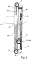
- Figure 2 shows a preferred embodiment of the actuating system of the sliding of the rotary table 11 on the guiding tower 7.
- Such sliding is left to a mixed pulling and pushing system that exploits the combination of linear actuators and flexible means and is housed inside the guiding tower 7.
- One or more linear actuators 30, 31 are preferably placed inside the guiding tower 7 and move a single block 32 equipped with wheels 32A and 32B on which the flexible means 33A and 33B wind.
- the flexible means 33A that drive the ascent are connected with one of their ends to the carriage 16 and, after being transmitted by the upper wheels 34 and by the wheels 32A of the block 32, connect with the other end to a first cable end 36.
- the flexible means 33B that drive the descent are connected with one of their ends to the carriage 16 and, after being transmitted by the lower wheels 35 and by the wheels 32B of the block 32, connected with the other end to a second cable end 37.
- the two cable ends 36 and 37 can be fixed directly to the body of the guiding tower 7, or with the interposition of a tensioner 38.
- This arrangement of the actuating system transfers to the carriage 16 a double stroke and a halved force with respect to those generated by the linear actuators 30, 31.
- the linear actuators 30, 31 consist of hydraulic cylinders
- the wheels 32A, 32B, 34 and 35 consist of pulleys
- the flexible means are cables.
- the wheels 32A, 32B, 34 and 35 can consist of toothed wheels and the flexible means 33A and 33B can consist of chains.
- the system for moving the rotary table 11, with the combined use of flexible means and linear actuators, is advantageous since it allows big displacements in proportion to its longitudinal bulk, greater power and speed with respect to those delivered by a winch and, simultaneously, a smaller transverse bulk that facilitates its insertion inside the guiding tower 7.
- plausible performance values provided by the push-pull system can be sliding of the carriage 16 of the order of 5-6 metres, total extraction pull of 200 tonnes and a thrust of 110 tonnes.
- the moving system described up to now allows the tube 300 to be driven in the ground carrying out a single continuous stroke of the rotary table 11, since such a stroke has a length comparable to or greater than the length of the tube 300 to be driven.
- the tubing device 100, equipped with such a moving system is advantageous with respect to known tube driving means, such as casing oscillators and "rotators", which on the other hand require driving of the tube with repeated strokes of limited width.
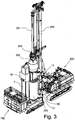
- FIG 3 shows the tubing device 100 that works in support to a known machine 200 to make piles (LDP).
- the machine 200 could also consist of a crane with scooper or any other apparatus suitable for excavating and/or demolishing and removing the ground confined by the tube 300.
- the excavation and/or pile driving machine 200 equipped with telescopic rods 201 and with an excavation tool 202 actuated by a rotary table 203, is located in work position with the excavation tool 202 completely lifted and arranged on the excavation axis of the pile.
- the tubing device 100 is located in the operative condition of start of driving the tube segment 300, with the tube operating unit 11 completely lifted and arranged on the excavation axis of the pile.
- the operating unit 11 is positioned in front of the guides of the tower 204 of the excavation machine and temporarily at a greater height with respect to the base of such a tower 204.
- the tube segment 300 is connected above the sleeve 12 and can be inserted into the space 14 of the base frame 1 that acts as a lower guide for the tube.
- the tubing device 100 can go into this position preferably by manoeuvring with its own tracks 1A and 1B, or it can be positioned through external moving means. During these positioning manoeuvres, the tube 300 may also not be loaded on the tubing device 100. Such loading can take place subsequently according to a procedure that will be described more clearly hereafter.
- the tubing device 100 can mechanically connect to the excavation and/or pile driving machine 200 through a shaft 1E that in its front part is suitably shaped to hook onto attachments that are normally present on the pile driving machines. Suitable attachments to the undercarriage of the machine 200 can be foreseen as provision for the connection of this external apparatus.
- This provision serves to discharge onto the undercarriage of the machine 200 part of the forces generated by the torque delivered by the tube operating unit 11 of the tubing device 100. This allows particularly high torques to be applied to the tube 300, since such torques no longer have to be discharged to the ground by the platforms 5A and 5B, and in this way the risk according to which the tubing device 100 could rotate with respect to the excavation axis is eliminated.
- the tube 300 if set in opposite rotation to that of the rotary table 203 that moves the excavation tool 202, can partially compensate these stresses without discharging them all to the ground.
- the mechanical connection between the base of the tower 204 and the front frame 1D of the tubing device 100 is of the friction type or, more advantageously, of the mechanical abutment type so that the excavation torques can be transmitted between the two parts in mechanical abutment.
- the shaft 1E has a telescopic structure moved by a linear actuator installed inside the shaft 1E itself, so as to be able to connect to different pile driving machines or to adapt to different work radii of one same excavation and/or pile driving machine 200.
- the shaft 1E is constrained to the openable front frame 1D through a hinge having horizontal axis, which allows the shaft 1E itself to be inclined by lifting its front part with respect to the ground. Such inclination can be adjusted by an actuator and allows quick hooking or unhooking of the shaft 1E from the attachments of the undercarriage of the machine 200.
- the telescopic elements of the shaft 1E have a circular section and can rotate with respect to one another on the longitudinal axis of the shaft 1E itself.
- This rotation combined with the adjustment of the inclination of the shaft 1E, makes it possible to compensate possible differences in inclination between the tracked carriage of the excavation and/or pile driving machine 200 and the base frame 1 of the tubing device 100.
- the carriage has the same inclination as the ground on which it rests, whereas in the tubing device 100 the base frame 1 is always kept horizontal by adjusting the stabilizers 4 and the platforms 5A and 5B to ensure the verticality of the guiding tower 7.
- the verticality of the tower 204 is obtained by acting on the linkage that connects such a tower 204 to the frame of the machine 200 itself.
- the tubed pile is made by progressively driving the tube 300 in the ground through the tubing device 100 and removing the ground from inside it through the excavation tool 202 actuated by the pile driving machine 200, or upon completion of the driving of the tube 300 or its partial driving when the ground is particularly hard and compact. While the excavation moves forwards, the tube segment 300 receives the torque and the thrust of the tube operating unit 11, which is moved and guided in the vertical direction on the guiding tower 7 of the tubing device 100.
- the dimensions of the operating unit 11 are particularly compact with respect to the diameter of the driven tube, in particular in the direction in front of the tower 7, and allow such an operating unit 11 and the rotary table 203 to slide in front of the guides of the tower 204 of the excavation machine 200 without interfering with it.
- the distance between the excavation axis and the front guides of the tower 204 limits the maximum diameter of the tube that it is possible to drive, in the case of coupling of the tubing device 100 with a pile driving machine of the LDP type.
- the excavation tool 202 and the telescopic rods 201 are inserted inside the tube 300 itself, crossing the aforementioned tube operating unit 11, and receive the torque and the thrust from the rotary table 203 that is moved and guided in the vertical direction on the tower 204 of the pile driving machine 200.
- the excavation tool 202 Once the excavation tool 202 has been loaded with ground moving forward in the excavation, it is made to ascend above the tube operating unit 11 through closing of the telescopic rods 201 and then, carrying out a rotation of the tower 204 with respect to the fifth wheel of the tracked carriage of the pile driving machine 200, it is emptied beside the machine itself.
- the clearance present between the front guides of the tower 204 and the outer structure of the operating unit 11 allows the rotation of the tower 204 even when the operating unit 11 is in front of such a tower 204. Thereafter, by completely lifting the excavation tool 202 and rotating the tower 204 in the opposite direction, it is possible to quickly reposition the tool 202 on the excavation axis to carry out another partial excavation.
- the excavation machine 200 is equipped with a foot at the base of its tower 204 it is preferable for this foot to be rested on the openable front frame 1D of the tubing device 100.
- the openable front frame 1D is suitably shaped and sized to allow such a manoeuvre. Through this operation it is possible to make part of the weight of the machine 200 bear down on the base frame 1 of the tubing device 100.
- the two machines 100 and 200 behave like a single rigid body during the thrusting of the tube 300.
- the tubing device 100 is prevented from lifting.
- the tube 300 is always kept moving forward, i.e. to at greater depths, with respect to the tool 202 so that the tool 202 itself works always guided by the tube 300.
- the associated work between the tubing device 100 and the machine 200 makes it possible to carry out simultaneous operations that would require much taller, heavier and more expensive machinery.
- the tubing device 100 can be equipped with an articulated crane dedicated to loading and positioning the sections of tube 300.
- Such a crane can be installed for example onto the central frame 1C and can be supplied with power by the same power group 3 of the tubing device 100, thus making it autonomous also in this task.
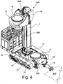
- Figure 4 illustrates the tubing device 100 with the guiding tower 7 arranged in a configuration such as to allow the loading of another section of tube 300 to be driven.
- the tubing device 100 is hooked (like in figure 3 ) to the undercarriage of the excavation and/or pile driving machine 200 through its adjustable telescopic shaft 1E and rests on the ground through the platforms 5A and 5B, which make the tubing device 100 itself perfectly horizontal and coaxial to the pile to be made. Since the tube segment 300 to be added can be positioned on the excavation axis keeping it suspended with a cable, it is necessary for the space above the excavation axis to be completely free and allow access both of the tube 300, and of the cable.
- the tubing device 100 foresees the possibility of moving the tube operating unit 11 into offset position with respect to the excavation axis, so as to completely free the passage over the space 14 of the base frame 1 and over the tube 300 already driven in the ground.
- such displacement takes place through a rotation of the guiding tower 7 about its longitudinal axis, which is parallel to the excavation axis.
- the tower support 15 is fixed to the central frame 1C in a rotatable manner about a vertical axis parallel to the excavation axis and is locked in the direction longitudinal to the aforementioned axis so as to be able to transmit to the base frame 1 both the thrust, and the vertical pull.
- the tower support 15 can extend inside the central frame 1C to obtain a more rigid connection and rotates on a bearing or on a fifth wheel.
- the rotation of the tower support 15 is driven by the unit 10 for moving the guiding tower 7, which includes actuators supplied by the power unit 3.
- These actuators can preferably be geared motors, linear actuators or cable systems.
- the angle of rotation of the tower support 15 generally has a width of at least 90°, but preferably a complete rotation of 360° is possible, always keeping the possibility of stopping such a rotation also at angles of less than 90°.
- the rotation of the tower support 15 is locked through one or more devices 17 for blocking the rotation.
- Such devices 17 for blocking the rotation are pins or pegs preferably arranged on the central frame 1C, moved by linear actuators, which can engage in suitable spaces present on the tower support 15 so as to couple it with the aforementioned central frame 1C.
- the devices 17 for blocking the rotation When the devices 17 for blocking the rotation are engaged, they can support and transmit to the central frame 1C the torque that is applied to the guiding tower 7. In this way the actuators of the unit 10 for moving the guiding tower 7 are prevented from being strained, which can thus be sized only to carry out such a rotation manoeuvre.
- the devices 17 for blocking the rotation are disengaged so as to temporarily decouple the rotation of the tower support 15 and the guiding tower 7 with respect to the base frame 1, after which the rotary table 11 is translated up to the maximum allowed height. Thereafter, the tower support 15, the guiding tower 7 and the tube operating unit 11 are moved in rotation until the space above the space 14 of the central frame 1C is completely freed, taking the bulk of the rotary table 11 and of the sleeve 12 completely outside of the passage required for the tube 300.
- the guiding tower 7 and the tube operating unit 11 in rotation, after having temporarily decoupled the guiding tower 7 with respect to the base frame 1, with respect to a horizontal axis present in the tower support 15, instead of with respect to a vertical axis as described earlier, so as to incline the guiding tower 7 itself laterally or at the rear with respect to the excavation axis until the bulk of the rotary table 11 and of the sleeve 12 is completely outside of the passage required for the tube 300.
- the guiding tower 7 is operatively connected to the base frame 1 directly, without the interposition of a tower support 15 and in which the guiding tower 7 is inclined laterally or at the rear setting it in rotation with respect to a horizontal axis present in the base frame 1.
- the tube operating unit 11 could temporarily be released from the carriage 16 and rotate about a vertical axis or translate, being guided by a guide present on the carriage 16 and moving on a horizontal plane until its bulk is brought completely outside the passage required for the tube 300. In such a solution it is not necessary for the guiding tower 7 and the tower support 15 to be rotatable.
- the excavation and/or pile driving machine 200 positions the new tube segment 300 on the excavation axis, resting it on the segment already driven. At this point the lower end of the new segment is joined to the upper end of the segment already driven through known connection elements, such as screws or pins.
- connection elements such as screws or pins.
- the loading step can proceed by carrying out a reverse rotation of the guiding tower 7 and of the tower support 15 so as to take the tube operating unit 11 and its sleeve 12 onto the excavation axis.
- the sleeve 12 will be higher up with respect to the upper end of the loaded tube segment 300. It proceeds by lowering the rotary table 11 along the guiding tower 7 until the system 13 for the automatic hooking and unhooking present in the lower part of the sleeve 12 is made to coincide, in height and in angle with the respective connection points arranged in the upper part of the tube segment 300.
- the presence of the system 13 for the automatic hooking and unhooking is advantageous since it makes it possible to carry out the connection between sleeve 12 and tube 300 without requiring worksite workers to climb up (for example five or six metres above ground) to manually make the connection. This speeds up the connection operations and makes them safer.
- the definition of such a system 13 for the automatic hooking and unhooking is not, however, encompassed in the scope of protection of the invention and the system 13 itself is not strictly necessary, since the connection can still be carried out in a conventional manner according to the procedures of the prior art.
- the tube 300 is guided both on top by the sleeve 12, in turn guided by the guiding tower 7, and at the bottom by the space 14 of the central frame 1C.
- the fact that these guide elements are very far apart (with respect to the guide elements present in a "rotator” or in a casing oscillator) further improves the verticality of the tube segment and therefore of the excavation.
- it is possible to tube the pile by adding new tube segments 300 until the design height is reached, and/or in any case up to a height dependent on the diameter of the tube and on the consistency of the ground.
- the excavation and/or pile driving machine 200 can excavate the core of ground autonomously from the tube 300 moving forward.
- the excavation machine 200 will stop its excavation work only to carry out the lifting and the positioning of another section of tube 300 on the column of those already driven. It can be presumed, due to the versatility of the tubing device 100 according to the present invention, that it is possible to drive sections of tube 300 with diameters varying between 1000 and 3000 millimetres and with lengths that can be from 1 to 5 times the diameter. Such lengths, therefore, preferably vary between 1.5 metres and 6 metres.
- the reinforcement cage is inserted and the pile is cast, for example through casting tubes according to the methodology known in the field.
- the casting is complete, it is necessary to carry out the extraction and unloading, i.e. the separation from the battery, of the tube segments 300.
- Such an operation can be carried out by the tubing device 100. by reversing the sequence of operations described for the loading of the tube segments 300.
- the gripping devices 18 of the tube mounted on the base frame 1 and that face onto the space 14 it is possible to grip the tube segment immediately below the one to be unloaded, so as to prevent the vertical translation of the battery of tubes inside the excavation.
- the upper tube segment can be disconnected from the sleeve 12 and from the tube segment below and, after having rotated the guiding tower 7 to free the passage, it is possible to lift the tube segment and unload it from the tubing device 100.
- the gripping devices 18 are deactivated and a new extraction is carried out. The operations are repeated until all of the tubes are extracted from the excavation.
- the tubing device 100 can operate totally autonomously, even without the presence of the excavation and/or pile driving machine 200 if a support crane is available for unloading the tube segments 300.
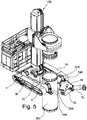
- the tubing device 100 can disengage from the tube of the pile and move onto the axis of a new pile. Such an advantageous characteristic can be better explained with reference to figure 5.
- Figure 5 indeed highlights the ability of the tubing device 100 to move part of its base frame 1 to release from the driven tube segment 300, irrespective of the height of tube that protrudes from the ground surface and crosses the central frame 1C through the space 14.
- the moveable front frame 1D in the preferred embodiment, is coupled with the central frame 1C through two hinges 19A and 19B with vertical axis, in which respective pins 20A and 20B are inserted.
- Such hinges 19A and 19B are positioned at the front end of the central frame 1C, where it takes up the characteristic C-shape, and arranged on the two opposite lateral flanks.
- the sleeve 12 and the rotary table 11 must be lifted by a small amount along the guiding tower 7, so as to be certain not to come back into contact with the tube segment 300 at the moment when the tubing device 100 rest back on its tracks 1A and 1B. Thereafter, if the tubing device 100 is connected to the excavation and/or pile driving machine 200 arranged in front of it, the telescopic shaft 1E is manoeuvred so as to unhook it from the attachments present on the excavation and/or pile driving machine 200 itself. The platforms 5A and 5B are then lifted through the stabilizers 4, thus allowing the tubing device 100 to rest back on its tracks 1A and 1B.
- the rotation of the moveable frame 1D is preferably generated by actuators, such as hydraulic cylinders or geared motors, suitably coupled with the moveable frame 1D and with the fixed frame 1C so as to generate relative motion. It is thus possible to use the translation itself of the tubing device 100 to generate the movement of the moveable frame 1D.
- actuators such as hydraulic cylinders or geared motors
- Another possible solution, not preferred but able to be used in emergencies, is that of disconnecting both pins 20A and 20B so as to completely separate the moveable frame 1D from the load-bearing frame 1C.
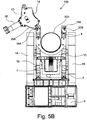
- Figure 5B shows a view from above of the tubing device 100 in the operative step in which the moveable frame 1D is opened to allow the tubing device 100 itself to disengage from the tube 300 driven into the ground even when such a tube 300 extends inside the base frame 1, at least partially crossing it, and in particular inside the space 14.
- figure 5B does not show the tube operating unit 11.
- figure 5B clearly shows that the arc followed by the moveable frame 1D is sufficient to create a front opening in the fixed frame 1C such as to allow the passage, in a longitudinal direction and parallel to the tracks 1A and 1B, of the tube 300.
- the front moveable frame 1D can be hinged to the central frame 1C through hinges having horizontal axis, so that it can be inclined with respect to the ground until it is rotated by 90°, taking the shaft 1E into substantially vertical position. Also in this case a front opening is produced that is sufficient to make the tube 300 come out from the space 14, but with the drawback that the tube must protrude from the ground by a limited height, such as to be able to pass beneath the moveable frame 1D.
- the front moveable frame 1D can be coupled with the central frame 1C through vertical guides that allow it to slide vertically up to a height greater than the central frame 1C, so that the offsetting creates a front opening of the space 14 allowing the disengagement of the tube 300.
- This embodiment also has the drawback that the tube 300 must protrude from the ground by a limited height, such as to be able to pass beneath the moveable frame 1D.
- the tubing device 100 can temporarily open the front frame 1D to couple on a tube driven into the ground and then enclose the moveable frame 1D to proceed with the extraction step of the tube.
- the load-bearing frame 1C in its C-shaped front part, is sized so as to be able to support the loads generated by the translation of the tubing device 100 even when the moveable front frame 1D is temporarily disconnected from the load-bearing frame 1C.
- a second excavation machine could have a second shaft on which the tubing device 100 engages, or furthermore the shaft could be dismounted from the first excavation machine 200 and it could be assembled on the tubing device 100 or on the second excavation machine.
- the tubing device 100 could be equipped with many guide towers 7, preferably two, coupled with the base frame 1.
- the tube operating unit 11 can slide, being guided on many guide towers through one or more carriages 16.
- the guide towers 7 are in opposite positions with respect to the driving axis of the tube and/or with respect to the middle planes of the tube operating unit 11. In this way, the guide towers 7 and the tube operating unit 11 form portal structures that are advantageous since, thanks to their symmetry, they reduce the flexional loads acting on the guide towers 7 themselves and on the bearing of the sleeve 12.
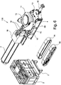
- Figure 6 shows how the tubing device 100 can be partially disassembled to promote its road transportation on a low loader or on a generic trailer for a truck. Since the at least one guiding tower 7 must allow a stroke of the tube operating unit 11 proportional to at least once the diameter of the tube 300, typically at least equal to the length of the tube 300 itself, such a guiding tower 7 has maximum vertical overall dimensions, when arranged in operative conditions of driving or extraction, not compatible with the limitations of road transportation. In order to take the tubing device 100 into a rest configuration or a configuration compatible with transportation it is possible to temporarily release the guiding tower 7 with respect to the base frame 1 and move it so that it is arranged in a condition of minimum vertical overall dimensions.
- the sleeve 12 inserts inside the space 14 of the base frame 1 until the body of the tube operating unit 11 rests on suitable abutments present on the central frame 1C. At this point it is possible to disconnect the rotary table 11 from the carriage 16 disengaging the connection pins, preferably actuated by remotely driven actuators. It proceeds by lifting the carriage 16 until it is brought above the bulk of the rotary table 11. At this point the carriage 16 is connected to the tower support 15 through at least one rigid element 19 that is shaped like a connecting rod.
- the rigid element 19 has one end hinged to the carriage 16 and the other end hinged to the tower support 15 through pins.
- the devices 17 for blocking the rotation of the tower support 15 are disengaged and, through the tower moving unit 10, a rotation of 180° of the tower support 15 and of the guiding tower 7 is performed.
- the bracketed support frame 2 is then disconnected from the load-bearing frame 1C.
- the group formed by the support frame 2 and the power unit 3 is moved for example laterally to the load-bearing frame 1C, through external lifting means, without interrupting the hydraulic connections between the power unit 3 and the actuators of the tubing device 100.
- the pins arranged on the second hinging axis 9 of the guiding tower 7 are disengaged, so as to release the guiding tower 7 from the base frame 1, freeing its rotation with respect to the first hinging axis 8.
- the carriage 16 By lowering the carriage 16 it is possible to load the rigid elements 19 by compression and generate a tilting moment with respect to the first hinging axis 8 of the guiding tower 7, so that such a guiding tower 7 inclines by rotating with respect to the first hinging axis 8.
- the guiding tower 7 itself inclines increasingly until the substantially horizontal transportation configuration is reached.
- the guiding tower 7 is lowered, i.e. it has a minimum bulk in height lower than the vertical work condition.
- the push-pull system of the carriage 16 allows such a carriage 16 to be stopped in any intermediate position of the guiding tower 7, avoiding uncontrolled movements of the guiding tower 7 itself during the descent.
- the weight of the unit 11 for moving the tube, bearing down directly on the central frame 1C, contributes to maintaining the stability of the tubing device 100 during the lowering of the guiding tower 7. Once this configuration has been reached it is possible to disconnect the tracks 1A and 1B from the load-bearing frame 1C so as to reduce the lateral bulk.
- the tubing device 100 in the transportation configuration without the tracks 1A and 1B, without the support frame 2 and without the power unit 3, has a weight and dimensions such as to allow transportation on a standard low loader, i.e. of the same type normally used for conventional pile driving machines. This is particularly advantageous because it allows the tubing device 100 to be transported without special permits for road transportation.
- the group formed by the remaining components 1A, 1B, 2 and 3 is in turn transportable on a second truck respecting the weight and bulk limits set for road transportation.
- the tubing device 100 is brought back into the conditions of figure 1 .
- the possibility of exploiting the movement of the carriage 16 to lift or lower the guiding tower 7 is advantageous, since it avoids having to use a support crane and it allows the guiding tower 7 to always be kept connected to the tubing device 100.
- the fact that the carriage 16 can remain mounted on the guiding tower 7 also in the transportation step is advantageous, since it avoids having to disconnect the flexible means 33A and 33B from the carriage 16.
- the guide tower(s) 7 could be released from the base frame 1, separating them completely from the latter so that they can be arranged with a yet lower vertical bulk on the means of transport, for example by resting them on the same plane on which the base frame 1 lies.
- the guide tower(s) 7 could consist of many telescopic sections, so that their length can be reduced by limiting the vertical bulk when they are not in operative configuration.
- the device for deep driving tubes having a large diameter achieves the purposes outlined earlier, in particular obtaining the following advantages:
- the device for deep driving tubes having a large diameter of the present invention thus conceived can in any case undergo numerous modifications and variants, all of which are covered by the same inventive concept; moreover, all of the details can be replaced by technically equivalent elements.
- the materials used, as well as the shapes and sizes, can be whatever according to the technical requirements. The scope of protection of the invention is therefore defined by the attached claims.
Landscapes
- Engineering & Computer Science (AREA)
- Structural Engineering (AREA)
- General Engineering & Computer Science (AREA)
- Life Sciences & Earth Sciences (AREA)
- General Life Sciences & Earth Sciences (AREA)
- Mining & Mineral Resources (AREA)
- Paleontology (AREA)
- Civil Engineering (AREA)
- Earth Drilling (AREA)
- Placing Or Removing Of Piles Or Sheet Piles, Or Accessories Thereof (AREA)
Description
- The present invention refers to a device for driving in the ground or extracting from the ground tube segments having a large diameter, such as known from
EP. 2 275 604 A . - In the field of foundations it is often required to have excavations having a large diameter, at great depth and with minimal deviations with respect to their vertical axis. An example of application in which such excavations are required consists of making impermeable partitions carried out through intersecting piles. In these cases the guarantee of actual interpenetration of the primary and secondary piles, closely linked to the verticality of the excavations, is an essential condition to carry out the work correctly. The uncertainty of the verticality of the pile leads to onerous corrective choices, the most obvious of which is to reduce the pitch between the axes of the intersecting piles so as to compensate, with greater interpenetration, the possible deviations that can be created between adjacent piles. Of course, this translates into over-consumption of cement mixture and into longer work times in making a partition of known length.
- The use of a guide tube to drive to the bottom of the excavation, which can act as a guide for the excavation tool, ensures better verticality of the pile. This is due to the much more rigid configuration of the tube with respect to that of a battery of telescopic rods or of a continuous helix, and the greatest advantages are obtained in the case in which layers of earth of very variable conformity and hardness are crossed. The use of the guide tube, (generally called "casing"), due to the high friction that is generated with the walls of the excavation, requires greater torques and greater pull-push forces at the excavation machines. In particular, such friction increases as the length and diameter of the guide tube increase. This means that above certain diameter and depth values it becomes disadvantageous to make a single machine that performs both the driving of the tube, and the excavation, since such a machine would have to be too big and cost too much. The use of external apparatuses connected to the excavation machine can allow greater diameters and tubing depths, but it greatly limits the mobility and speed of the excavation machine, as well as increasing costs.
- Known machinery for making tubed piles can be substantially split into two categories, as a function of the depth of the pile. In order to make piles of medium-low depth, quantifiable in the value of 30-35 metres at most, it is foreseen to use a tracked machine equipped with a vertical tower, along which two rotary tables, commonly called "rotaries", can slide, one on top of the other, in a constrained or independent manner. The two rotary tables both translate on the .same sliding guides present in the tower. The upper rotary table sets a helix in translation and in rotation, said helix being equipped in its lower part with a tip with excavation teeth and has a length substantially equal to that of the tower. The lower rotary table sets a coating tube in translation and in rotation, usually in the opposite sense of rotation to that of the helix. The tube and the lower rotary table have a diameter such as to make the helix transit inside them, actuated by the upper rotary table. The tube is equipped with blades in its lower part and in its thickness in contact with the ground, so as to separate, while moving forward, a core of ground that will later be broken up and lifted by the helix above. The broken up ground is loaded by the auger of the helix and sent outside of the excavation.
- The tube has a maximum installable length that is substantially less than that of the helix and that can be determined by subtracting the length of the rotary table that moves the tube itself from the length of the helix. The lower rotary table, commonly called "tubing device", can generally have a length of about 3 metres. As a result, when the pile is finished, the tubed part represents a fraction of the total length of the excavation, generally not more than 2/3. It is not foreseen, in this type of equipment, to join additional tube or helix elements as the excavation progresses. Consequently, the depth reachable by the helix corresponds to about the length of the tower of the machine and the depth reachable by the tube depends on the maximum loadable length below the lower rotary table.
- It is difficult for the maximum depth to exceed 30 metres, because for greater depths the machine would have to have a tower that is too long, which would be too heavy for the machine and could cause instability. On the other hand, it would be necessary to make extremely heavy and bulky machines, but becoming incompatible with all urban works where the spaces available are small. Moreover, a machine with such a long guiding tower would be difficult to transport. As the length of the tube increases, the thrust required to drive it also increases, but such a thrust must be limited based on the weight of the machine, which otherwise would tend to lift at the front. A greater tubed depth implies a greater weight of the battery of tubes and thus requires a greater extraction force of the machine, but also such an extraction force must be limited based on the size of the machine and the resistance of the tracked undercarriage. The maximum usable diameter for the tube depends on the maximum torque able to be delivered by the lower rotary table and also this must be limited based on the torsional resistance of the tower. Such resistance depends on the section and on the thicknesses of the tower. Also in this case, by exceeding certain limit values, the tower would be too heavy.
- The driving of a tube having a diameter equal to 1200 millimetres to a depth of 20 metres seems to represent, as things stand, the performance limit that can be obtained by a single machine with two rotary tables. The advantageous aspects of this type of machinery ("cased secant piles" or CSP) for shallow excavations consist of the fact that the machine is relatively light and thus easy to manoeuvre and transport, it does not have support structures at the excavation, such as casing oscillators, and it moves autonomously within the worksite from one point of construction of the pile to another without the help of external transportation means. Moreover, the excavation can take place dry, without the addition of stabilizing liquids to support the walls. The absence of recycling means of such liquids, associated with the absence of vibrations, makes these CSP machines particularly suitable for use in urban settings. The addition of the cement mixture takes place through a conduit inside the shaft of the helix, with the help of an external pump. The extraction of the tube is preferably concurrent to the filling of the hole, so that the pressure exerted by the mixture can prevent the collapse of the walls no longer supported by the tube. In some cases it is possible to extract the tube at the end of filling the hole.
- In order to make piles of greater depth, greater than 30/35 metres, a tracked machine with a vertical tower is generally used, along which a single rotary table moves on suitable guides. The rotary table sets a battery of telescopic rods in rotary movement, at the base of which there is an excavation tool, like for example a "bucket" or a drill. This technology, called LDP (acronym for "large diameter pile") is generally used to make deep non-secant piles, where the limitations required for the deviation from verticality are less stringent. The use of telescopic rods makes it possible to reach much greater excavation depths with the tool with respect to the length of the tower on which the rotary table slides. LDP technology foresees that the final depth is obtained through repeated partial excavations, each of which involves the driving of the tool in the ground and results in an advancement equal to the length of the tool itself. Each partial excavation is obtained by applying a thrust and a rotation on the tool and, when the tool is full, the operator lifts it up from the bottom of the excavation until it is brought above the terrain surface, where it is emptied beside the machine, onto the ground or into a truck.
- A drawback of LDP technology consists of the fact that, as the depth reached increases, the duration of the active excavation step, i.e. that for filling the tool, is increasingly short in proportion to the inactive steps of descent and ascent in the excavation. Another drawback is the fact that the pile is usually excavated with the addition of stabilizing materials that prevent the hole from collapsing, such as bentonite or polymers. The use of such stabilizers requires rather complex logistics and apparatus to obtain their recovery and recycling, like for example decanting and containment tanks, sieves, grit separators, etc. These apparatuses are difficult to adapt to use in tight urban spaces or in worksites that extend for many kilometres, requiring continuous movement of the equipment.
- The alternative to using stabilizing substances is to use, in combination with LDP technology, a coating guide tube that can support the walls of the hole, preventing it from collapsing. The use of the tube is particularly advantageous when excavating below the water table, since it manages to keep the outflow of ground water inside the excavation to acceptable levels. In this case, excavation is carried out "dry" and there is less need for logistics linked to stabilizing fluids. If the section of hole to be tubed has a limited depth, and in any case compatible with the power of the machine, it is possible to use the rotary table itself, mounting a hauling extension (cup) beneath it, which couples with the tube, to rotate and thrust the tube in the ground. Due to the axial bulk of the telescopic rods, which cannot extend above the head of the guiding tower, the free space for the positioning of the tube beneath the hauling extension is limited to a few metres, in general not more than six or seven. As a result, being forced to use short tubes, even for limited tubed depths it is necessary to drive in one piece of tube at a time, joining it to those already driven in. Therefore a lot of time is spent fixing together the pieces of casing tube, with spanners and bolts that are usually locked by hand.
- When the depth and/or the diameter to be made become high, the torque delivered by the rotary table of the machine is insufficient and external apparatuses become necessary, distinct from the machine, to drive the tube segments by rotation and thrusting up to the desired depth and to extract them at the end of the excavation. These apparatuses are usually bulky, heavy and expensive. The external apparatuses most commonly used are casing oscillators or "rotators" (full-rotators). These apparatuses are mainly made up of a monolithic base frame and a second upper frame that is moveable with respect to the first. Both of the frames develop about a central circular passage of large diameter, completely surrounding it. Such a central passage makes it possible to introduce a tube segment from above, crossing the frames, in order to drive it into the ground. Such apparatuses must therefore be positioned at the front of a common pile driving machine, at a lower height with respect to the base of the tower of the machine and aligning their central passage on the drilling axis of such a machine. Such apparatuses are equipped with suitable actuation means that connect the moveable upper frame to the base frame, allowing the upper frame to be made to perform vertical translations and rotations about the vertical axis of the central passage. Once the upper frame, through temporary gripping means, is able to transfer these movements to the tube to be driven. During its limited axial movement, the upper frame is not guided by any structural element of the apparatus, but only by the actuators and by the tube itself. In the casing oscillators the base frame rests directly on the ground. The upper frame is equipped with hydraulic clamps or jaws to grip or release the tube. All of the actuators of the clamp are usually fed by the hydraulic system of the pile driving machine. The thrusting takes place through hydraulic cylinders that bring the upper frame towards the base frame, whereas the rotation takes place, with partial and alternate movements, through a pair of hydraulic rotation cylinders mounted opposite one another. For every partial rotation it is necessary for the jaws to grip the tube, for the rotation cylinders to carry out their limited stroke, for the jaws to release the tube and for the rotation cylinders to carry out a reverse stroke to go back into the start of rotation condition. Therefore, very long cycle times are needed to carry out the excavation.
- A "rotator" in brief consists of a rotary table with a passage having a large diameter, which constitutes an upper frame and which is moveable with respect to a monolithic base frame that also extends around the passage of the table to allow the insertion of the tube. The base frame rests on the ground. The rotary table comprises a through sleeve on which geared motors are fitted that allow the rotation thereof. Such a sleeve is provided with hydraulic jaws that wrap around the tube to be driven on its outer surface, transmitting the rotation to it only by means of the friction between jaws and tube. Through hydraulic cylinders that connect the upper rotary table to the base frame it is possible to generate small and limited vertical movements, always less than one metre, and thus exert a thrust or a pull on the tube. The limited vertical movement of the upper frame is not, however, guided by a tower or by elements of the frame, but exploits just the rigidity of the actuators and of the tube itself. In particular, the axial movement is limited because the axial stroke available is always less than the length of the piece of tube that is joined. In some variants, the "rotator" can comprise an autonomous power unit to supply its own actuators. In rare cases the "rotator" is connected to the hydraulic system of the pile driving machine.
- The aforementioned external apparatuses for driving such tubes have numerous limitations and drawbacks. Firstly, the cylinders of both types of external apparatuses have limited strokes in the vertical direction, generally of the order of 400-600 millimetres, with consequent limited driving or extraction movements. In particular, the moveable part of these apparatuses, i.e. that capable of transmitting the thrust and the torque, even in the condition of maximum vertical stroke always remains at a height lower than the base of the tower of the machine. This is generally due to the substantial bulk of such apparatuses in the radial direction with respect to the excavation axis. Often, in order to allow the connection of such apparatuses to the machine it is necessary to dismount the lower segment of the tower of the machine. Strokes of greater width could lead to interference or collisions between the mobile part of the external driving apparatuses and the tower of the machine. As a result, in order to drive or extract a few tens of metres of tube a very large number of manoeuvres are needed, each of which comprises the steps of gripping, of translation and of release of the tube, and therefore takes a long time. A second limitation is due to the fact that the aforementioned external apparatuses, gripping the tube laterally through the upper frame, are not able to completely drive the tube until it is flush with the ground surface. In particular, the tube will always extend vertically above the base frame by a minimum amount sufficient to allow it to be gripped laterally. The tube, therefore, always extends at least partially inside such frames of the external apparatuses and, due to the fact that these frames are monolithic and completely surround the tube, the external apparatuses are fixedly connected to the driven tube, not being able to translate horizontally with respect to it. The aforementioned apparatuses, which actively operate only during the driving or extraction steps, are forced to remain on the axis of the pile even during the steps of casting and insertion of the cage that does not involve them. During the inactive steps, the driving apparatuses cannot be moved and exploited on other piles, unless they are lifted through a crane to axially disengage from the driven tube. This solution is, however, complex and not cost-effective.
- A further limitation of casing oscillators and of "rotators" is due to the fact that their hydraulic jaws transmit the torque by clamping the tube on its outer surface, only by friction, and this requires the use of very thick tubes or ones with a double wall to prevent it from becoming oval. These tubes are particularly heavy and expensive.
- The purpose of the present invention is therefore to make a device for driving in the ground or extracting from the ground tube segments having a large diameter that is able to solve the aforementioned drawbacks of the prior art in a simple, cost-effective and functional manner. The device according to the present invention, working in support of machines for excavating and making piles, is able to drive or extract tube segments having a large diameter in/from the ground through rotation and pushing or pulling, where the tube segments can have lengths equal to at least once the diameter, preferably from 2 to 5 times the diameter.
- In detail, a purpose of the present invention is to make a device for deep driving tubes having a large diameter that makes the driving and extraction steps of the tube faster, at the same time ensuring better verticality.
- Another purpose of the present invention is to make a device for deep driving tubes having a large diameter that is able to reduce the idle times, allowing better exploitation and better productivity of the driving apparatus, also thanks to the possibility of the device supporting many pile driving machines within the same worksite.
- The embodiments of the device according to the invention favour versatility, making an autonomous means in terms of movement and generation of power and capable of moving by its own means in the area of the worksite. The device has the ability to open a part of its frame at any moment to disengage from the driven tube and move with respect to it, to then be repositioned on it and re-engage at a later time to carry out the extraction. Such a later time is decided by the foreman of the worksite based on economic considerations, and may for example be after the steps of insertion of the reinforcement and of concrete casting. During such steps, which are carried out by independent machinery such as a crane and a concrete pump and that do not require the use of the tubing device, the device itself is able to move autonomously and be positioned on the axis of a second pile to perform the driving of the relative guide tube. At a later time, when the steps of casting and of insertion of the reinforcement of the first pile have ended, the tubing device can go back onto the axis of the first pile to extract the casings. Thanks to this special feature the tubing device can serve more than one LDP machine, being able to go back to and move away from the pile, i.e. being able to disengage from a first tube present on the excavation axis of a first LDP machine to engage on a second pile present on the excavation axis of a second LDP machine. This manoeuvre can be carried out at any stage of excavation desired, and consequently it is possible to drastically reduce the inactive times of the tubing device.
- The device according to the invention is advantageous with respect to a generic tubing machine with double "rotary" and continuous helix (CSP), as well as to conventional tubing devices such as casing oscillators or "rotators". The device according to the invention, indeed, being equipped with its own guiding tower, which is distinct from that of the pile driving machine and is much stronger, makes it possible to install on such a guiding tower a rotary table with much better performances in terms of torque and push-pull with respect to the rotary table that would be installable on the tower of the pile driving machine. Such performances are comparable to or better than that provided by casing oscillators or by "rotators" but, unlike such apparatuses, the device according to the invention makes it possible to drive the tube not through short steps with continuous restarts, but rather through a rotation associated with a continuous thrusting movement, able to be perfectly adjusted, the width of which is determined by the stroke of the rotary table on the guiding tower and is proportional to at least once the diameter of the section of tube to be moved. In particular, the stroke available is preferably greater than the length of the section of tube to be moved. In particular, the rotary table installed on the tower of the tubing device can, during its stroke, go to a height greater than the base of the tower of the machine. In greater detail, the rotary table can slide in front of the guides of the tower of the pile driving machine associated with the tubing device. The presence of the guiding tower ensures better verticality of the tubes during the driving step with respect to casing oscillators and to "rotators".
- A work method and a series of accessories and constructive solutions facilitate the loading and unloading steps of the tube segments, so as to make the operation safe and fast. The careful study of the work method, associated with the use of such accessories, makes a drilling machine that is versatile and of relatively low weight, and thus cost-effective, suitable for carrying out operations that would require much greater resources if carried out with methods of the prior art.
- The characteristics and advantages of a device for deep driving tubes having a large diameter according to the present invention will become clearer from the following description, given as an example and not for limiting purposes, referring to the attached schematic drawings, in which:
-
figure 1 is a perspective view of an example embodiment of the device for deep driving tubes having a large diameter according to the present invention; -
figure 2 is a transparent view of the tower of the device offigure 1 , illustrating a preferred embodiment of the relative actuation system for driving the translation of the rotary table; -
figure 3 is a perspective view of the device offigure 1 , coupled with a known machine equipped with telescopic rods and with a tool for the excavation of piles, in the initial driving step of the tube; -
figure 4 is a perspective view of the device offigure 1 in the operative step in which the tower is rotated to allow the addition of a new tube segment to be driven into the ground; -
figure 5 is a perspective view of the device offigure 1 in the operative step in which the frame is opened to allow the device itself to disengage from the tube driven into the ground; -
figure 5B is a view from above, in which the tube operating unit is not shown, of the device offigure 1 in the operative step in which the frame is opened to allow the device itself to disengage from the tube driven into the ground; and -
figure 6 is an exploded view that shows the groups in which the device offigure 1 can be disassembled to facilitate the transportation thereof on road vehicles. - With reference in particular to
figure 1 , an example embodiment of the device for deep driving tubes having a large diameter according to the present invention, or tubing device, is shown wholly indicated withreference numeral 100. Thetubing device 100 substantially consists of: - a base frame or
truck 1; - at least one guiding
tower 7, fixedly connected to thebase frame 1 through atower support 15; - a
unit 10 for moving the at least one guidingtower 7; - a
tube operating unit 11, able to slide on each guidingtower 7; - a bracketed
support frame 2; and - a
power group 3. - In particular, with respect to a middle vertical plane of the
tubing device 100 and in the operative condition of thetubing device 100 itself, thetube operating unit 11, the guidingtower 7 and thebase frame 1 can be assembled in a C-shaped configuration in which, due to stability and proportioning issues of the structures, the guidingtower 7 is in a slightly backward position with respect to the barycenter of thebase frame 1. - The
tubing device 100 is preferably self-propelled and, for this purpose, thebase frame 1 can be provided withtracks base frame 1 is in turn made up of a central load-bearing frame 1C and a moveable or openablefront frame 1D, which can comprise a preferablytelescopic shaft 1E. Thecentral frame 1C, if observed with respect to a horizontal plane or in a plan view, is characterised, in its front part, by a C-shape or semi-circle shape at the centre of which the driving or drilling axis of thetubing device 100 passes. Such a shape of thecentral frame 1C determines aspace 14 having a diameter sufficient to allow the passage of the tube segment 300 (seefigure 3 ) to be driven in the ground. Thefront frame 1D, when positioned in operative condition, closes thespace 14 in the radial direction. Thefront frame 1D, in its rear part, is shaped like a circular arc complementary to the shape of thespace 14 of thecentral frame 1C so that, in operative position, thespace 14 is circular shaped and can guide thetube 300 to be driven, keeping it vertical and centred on the driving axis. Thebase frame 1 is adapted to allow the dismounting of thetracks tubing device 100 during transportation, preferably to a value of less than 3.5 metres. - A
bracket support frame 2 is removably connected to the rear part of thecentral frame 1C to support thepower group 3. Such apower group 3 is of the known type and provides the flow rate and pressure of oil necessary to supply all of the hydraulic actuations of thetubing device 100. Thepower group 3 includes, in a per sé known way, a plurality of hydraulic pumps, a motor, preferably but not necessarily an internal combustion engine, to actuate such hydraulic pumps, tanks for the oil and possibly for the fuel and all of the necessary accessory systems. Alternatively, thepower group 3 could also be provided with electric motors, cables and electric actuators. - The
base frame 1 is equipped withstabilizers 4, preferably two on each flank of thecentral frame 1C, which move twoplatforms entire tubing device 100 to be kept stable on the ground. Preferably, theplatforms stabilizers 4 and eachstabilizer 4 can be actuated independently. In this way it is possible to adapt to the inclinations of the ground and ensure the verticality of the guidingtower 7, in order to obtain a vertical excavation. In particular, through thestabilizers 4 it is possible to vertically move theplatforms entire tubing device 100, so as to unburden thetracks tube 300. Advantageously, thetracks platform central frame 1C and has a width such as to be able to be placed between eachtrack space 14 of thecentral frame 1C without interfering with thetracks tube 300. Thanks to their great length, theplatforms entire tubing device 100. - The guiding
tower 7, with a substantially elongated shape, generally has a larger section and a shorter length with respect to the tower of a common pile driving machine, assuming a squat configuration. The guidingtower 7 is mounted on atower support 15 and is arranged along a vertical axis in the operative conditions of thetubing device 100. The guidingtower 7 is hinged to thetower support 15 on afirst axis 8, arranged horizontally, and can be locked in vertical position, for example through pins arranged on asecond hinging axis 9 that engage on the guidingtower 7 itself and on thetower support 15. The guidingtower 7 is equipped with guides on which acarriage 16 can slide that supports thetube operating unit 11. The guides are arranged parallel to the longitudinal axis of the guidingtower 7 and can be located on the front part of the guidingtower 7 itself or, preferably, both on the front part and on the rear part, so as to offer better guiding and a larger contact surface. Thecarriage 16 is moved through an actuation system, which will be described more clearly hereafter, and can transmit to thetube operating unit 11 forces directed both upwards and downwards. These forces can thus be exploited to push thetube 300 in the ground or to extract it from the ground. - The
tube operating unit 11 substantially consists of a rotary table equipped with a throughsleeve 12 by means of which there is application of a rotation and thus a torque about an axis parallel to the guidingtower 7, as well as of the pulling and thrusting forces in a direction parallel to the guidingtower 7. Thesleeve 12 has an internal diameter substantially equal to that of thetube 300 to be driven, so as to allow the passage of an excavation tool that, after having crossed thetube operating unit 11, can remove the ground enclosed in thetube 300 once it is driven. Thesleeve 12 has, in its lower part, asystem 13 for the automatic hooking and unhooking, of the known type, capable of coupling with or disengaging from thetube 300 without requiring the manual intervention of an operator. The hooking and unhookingsystem 13 allows the transmission of axial forces and torque between thesleeve 12 and thetube 300, for example through pin or peg-type connections. Thetube operating unit 11 is equipped with actuators capable of applying to the sleeve 12 a torque sufficient to set all of thetube segments 300 in rotation, overcoming the friction that develops betweensuch tube segments 300 and the ground during driving. Preferably these actuators consist of hydraulic geared motors fitted onto a toothed crown fixedly connected to thesleeve 12, which rotates on a fifth wheel or on a bearing. In particular, such actuators are suitably arranged around the toothed crown so as to obtain the minimum bulk of the rotary table in the frontal direction, i.e. in the opposite direction to the guidingtower 7 with respect to the excavation axis. In this way, it is possible to apply to thesleeve 12, and thus to thetube segment 300 connected to the sleeve, continuous complete rotations or partial alternate rotations about the longitudinal axis of the tube itself in both rotation senses. Thesleeve 12 and the hookingsystem 13 are thus engaging means capable both of selectively holding thetube segment 300, and of transmitting to said tube segment 300 a rotary motion and an axial sliding movement. -
Figure 2 shows a preferred embodiment of the actuating system of the sliding of the rotary table 11 on the guidingtower 7. Such sliding is left to a mixed pulling and pushing system that exploits the combination of linear actuators and flexible means and is housed inside the guidingtower 7. One or more linear actuators 30, 31 are preferably placed inside the guidingtower 7 and move asingle block 32 equipped withwheels carriage 16 and, after being transmitted by theupper wheels 34 and by thewheels 32A of theblock 32, connect with the other end to afirst cable end 36. The flexible means 33B that drive the descent are connected with one of their ends to thecarriage 16 and, after being transmitted by thelower wheels 35 and by thewheels 32B of theblock 32, connected with the other end to asecond cable end 37. The two cable ends 36 and 37 can be fixed directly to the body of the guidingtower 7, or with the interposition of atensioner 38. This arrangement of the actuating system transfers to the carriage 16 a double stroke and a halved force with respect to those generated by the linear actuators 30, 31. In the preferred embodiment, the linear actuators 30, 31 consist of hydraulic cylinders, thewheels wheels - The system for moving the rotary table 11, with the combined use of flexible means and linear actuators, is advantageous since it allows big displacements in proportion to its longitudinal bulk, greater power and speed with respect to those delivered by a winch and, simultaneously, a smaller transverse bulk that facilitates its insertion inside the guiding
tower 7. As an example, plausible performance values provided by the push-pull system can be sliding of thecarriage 16 of the order of 5-6 metres, total extraction pull of 200 tonnes and a thrust of 110 tonnes. The moving system described up to now allows thetube 300 to be driven in the ground carrying out a single continuous stroke of the rotary table 11, since such a stroke has a length comparable to or greater than the length of thetube 300 to be driven. Thetubing device 100, equipped with such a moving system, is advantageous with respect to known tube driving means, such as casing oscillators and "rotators", which on the other hand require driving of the tube with repeated strokes of limited width. -
Figure 3 shows thetubing device 100 that works in support to a knownmachine 200 to make piles (LDP). Themachine 200 could also consist of a crane with scooper or any other apparatus suitable for excavating and/or demolishing and removing the ground confined by thetube 300. The excavation and/orpile driving machine 200, equipped withtelescopic rods 201 and with anexcavation tool 202 actuated by a rotary table 203, is located in work position with theexcavation tool 202 completely lifted and arranged on the excavation axis of the pile. Thetubing device 100 is located in the operative condition of start of driving thetube segment 300, with thetube operating unit 11 completely lifted and arranged on the excavation axis of the pile. In particular, the operatingunit 11 is positioned in front of the guides of thetower 204 of the excavation machine and temporarily at a greater height with respect to the base of such atower 204. Thetube segment 300 is connected above thesleeve 12 and can be inserted into thespace 14 of thebase frame 1 that acts as a lower guide for the tube. Thetubing device 100 can go into this position preferably by manoeuvring with itsown tracks tube 300 may also not be loaded on thetubing device 100. Such loading can take place subsequently according to a procedure that will be described more clearly hereafter. - The
tubing device 100 can mechanically connect to the excavation and/orpile driving machine 200 through ashaft 1E that in its front part is suitably shaped to hook onto attachments that are normally present on the pile driving machines. Suitable attachments to the undercarriage of themachine 200 can be foreseen as provision for the connection of this external apparatus. This provision serves to discharge onto the undercarriage of themachine 200 part of the forces generated by the torque delivered by thetube operating unit 11 of thetubing device 100. This allows particularly high torques to be applied to thetube 300, since such torques no longer have to be discharged to the ground by theplatforms tubing device 100 could rotate with respect to the excavation axis is eliminated. This configuration is particularly advantageous because thetube 300, if set in opposite rotation to that of the rotary table 203 that moves theexcavation tool 202, can partially compensate these stresses without discharging them all to the ground. In particular, the mechanical connection between the base of thetower 204 and thefront frame 1D of thetubing device 100 is of the friction type or, more advantageously, of the mechanical abutment type so that the excavation torques can be transmitted between the two parts in mechanical abutment. - Preferably, the
shaft 1E has a telescopic structure moved by a linear actuator installed inside theshaft 1E itself, so as to be able to connect to different pile driving machines or to adapt to different work radii of one same excavation and/orpile driving machine 200. Theshaft 1E is constrained to the openablefront frame 1D through a hinge having horizontal axis, which allows theshaft 1E itself to be inclined by lifting its front part with respect to the ground. Such inclination can be adjusted by an actuator and allows quick hooking or unhooking of theshaft 1E from the attachments of the undercarriage of themachine 200. Preferably, the telescopic elements of theshaft 1E have a circular section and can rotate with respect to one another on the longitudinal axis of theshaft 1E itself. This rotation, combined with the adjustment of the inclination of theshaft 1E, makes it possible to compensate possible differences in inclination between the tracked carriage of the excavation and/orpile driving machine 200 and thebase frame 1 of thetubing device 100. Indeed, in theexcavation machine 200 the carriage has the same inclination as the ground on which it rests, whereas in thetubing device 100 thebase frame 1 is always kept horizontal by adjusting thestabilizers 4 and theplatforms tower 7. In theexcavation machine 200 the verticality of thetower 204 is obtained by acting on the linkage that connects such atower 204 to the frame of themachine 200 itself. - Again with reference to
figure 3 , it is possible to see how the tubed pile is made by progressively driving thetube 300 in the ground through thetubing device 100 and removing the ground from inside it through theexcavation tool 202 actuated by thepile driving machine 200, or upon completion of the driving of thetube 300 or its partial driving when the ground is particularly hard and compact. While the excavation moves forwards, thetube segment 300 receives the torque and the thrust of thetube operating unit 11, which is moved and guided in the vertical direction on the guidingtower 7 of thetubing device 100. The dimensions of the operatingunit 11 are particularly compact with respect to the diameter of the driven tube, in particular in the direction in front of thetower 7, and allow such anoperating unit 11 and the rotary table 203 to slide in front of the guides of thetower 204 of theexcavation machine 200 without interfering with it. The distance between the excavation axis and the front guides of thetower 204 limits the maximum diameter of the tube that it is possible to drive, in the case of coupling of thetubing device 100 with a pile driving machine of the LDP type. During the emptying step of thetube 300, theexcavation tool 202 and thetelescopic rods 201 are inserted inside thetube 300 itself, crossing the aforementionedtube operating unit 11, and receive the torque and the thrust from the rotary table 203 that is moved and guided in the vertical direction on thetower 204 of thepile driving machine 200. Once theexcavation tool 202 has been loaded with ground moving forward in the excavation, it is made to ascend above thetube operating unit 11 through closing of thetelescopic rods 201 and then, carrying out a rotation of thetower 204 with respect to the fifth wheel of the tracked carriage of thepile driving machine 200, it is emptied beside the machine itself. The clearance present between the front guides of thetower 204 and the outer structure of the operatingunit 11 allows the rotation of thetower 204 even when the operatingunit 11 is in front of such atower 204. Thereafter, by completely lifting theexcavation tool 202 and rotating thetower 204 in the opposite direction, it is possible to quickly reposition thetool 202 on the excavation axis to carry out another partial excavation. - During the thrusting step of the
tube 300 in the ground through thetubing device 100, if theexcavation machine 200 is equipped with a foot at the base of itstower 204 it is preferable for this foot to be rested on the openablefront frame 1D of thetubing device 100. The openablefront frame 1D is suitably shaped and sized to allow such a manoeuvre. Through this operation it is possible to make part of the weight of themachine 200 bear down on thebase frame 1 of thetubing device 100. In particular, thanks to the mechanical connection of theshaft 1E and the resting of the foot of thetower 204 on the openablefront frame 1D, the twomachines tube 300. In this way it is possible to apply very large thrusts to thetube 300, in particular greater than the weight of thetubing device 100 itself, since the weight of themachine 200 also helps with the stability of the assembly. In particular, thetubing device 100 is prevented from lifting. Preferably, during driving, thetube 300 is always kept moving forward, i.e. to at greater depths, with respect to thetool 202 so that thetool 202 itself works always guided by thetube 300. The associated work between thetubing device 100 and themachine 200 makes it possible to carry out simultaneous operations that would require much taller, heavier and more expensive machinery. - Once the insertion in the ground of a
tube element 300 has been completed, through thesystem 13 for the automatic hooking and unhooking thesleeve 12 is disconnected from thetube segment 300 and anothertube segment 300 is loaded. Such a step will be better described hereafter with reference tofigure 4 . The loading of sections under the rotary table 11 of thetubing device 100 is preferably left to the excavation and/orpile driving machine 200, exploiting the service cable with which it is normally equipped. Such a service cable is actuated by a dedicated winch of themachine 200 and, after having been transmitted over the head of thetower 204, is arranged parallel to thetelescopic rods 201 and to the same work radius. Therefore, through a simple rotation of thetower 204, such a cable is arranged on the excavation axis. This solution is advantageous because it does not require the presence of a service crane to support themachines tube 300 is to connect it to theexcavation tool 202, for example through cables or chains, and exploit the vertical movement of the battery ofrods 201. In a further embodiment, thetubing device 100 can be equipped with an articulated crane dedicated to loading and positioning the sections oftube 300. Such a crane can be installed for example onto thecentral frame 1C and can be supplied with power by thesame power group 3 of thetubing device 100, thus making it autonomous also in this task. -
Figure 4 illustrates thetubing device 100 with the guidingtower 7 arranged in a configuration such as to allow the loading of another section oftube 300 to be driven. Thetubing device 100 is hooked (like infigure 3 ) to the undercarriage of the excavation and/orpile driving machine 200 through its adjustabletelescopic shaft 1E and rests on the ground through theplatforms tubing device 100 itself perfectly horizontal and coaxial to the pile to be made. Since thetube segment 300 to be added can be positioned on the excavation axis keeping it suspended with a cable, it is necessary for the space above the excavation axis to be completely free and allow access both of thetube 300, and of the cable. For this purpose, thetubing device 100 foresees the possibility of moving thetube operating unit 11 into offset position with respect to the excavation axis, so as to completely free the passage over thespace 14 of thebase frame 1 and over thetube 300 already driven in the ground. Preferably, such displacement takes place through a rotation of the guidingtower 7 about its longitudinal axis, which is parallel to the excavation axis. - In the preferred embodiment shown in
figure 4 , thetower support 15 is fixed to thecentral frame 1C in a rotatable manner about a vertical axis parallel to the excavation axis and is locked in the direction longitudinal to the aforementioned axis so as to be able to transmit to thebase frame 1 both the thrust, and the vertical pull. Thetower support 15 can extend inside thecentral frame 1C to obtain a more rigid connection and rotates on a bearing or on a fifth wheel. The rotation of thetower support 15 is driven by theunit 10 for moving the guidingtower 7, which includes actuators supplied by thepower unit 3. These actuators can preferably be geared motors, linear actuators or cable systems. The angle of rotation of thetower support 15 generally has a width of at least 90°, but preferably a complete rotation of 360° is possible, always keeping the possibility of stopping such a rotation also at angles of less than 90°. During the excavation and driving steps of thetube 300, the rotation of thetower support 15 is locked through one ormore devices 17 for blocking the rotation.Such devices 17 for blocking the rotation are pins or pegs preferably arranged on thecentral frame 1C, moved by linear actuators, which can engage in suitable spaces present on thetower support 15 so as to couple it with the aforementionedcentral frame 1C. When thedevices 17 for blocking the rotation are engaged, they can support and transmit to thecentral frame 1C the torque that is applied to the guidingtower 7. In this way the actuators of theunit 10 for moving the guidingtower 7 are prevented from being strained, which can thus be sized only to carry out such a rotation manoeuvre. - During the loading step of another
tube segment 300, thedevices 17 for blocking the rotation are disengaged so as to temporarily decouple the rotation of thetower support 15 and the guidingtower 7 with respect to thebase frame 1, after which the rotary table 11 is translated up to the maximum allowed height. Thereafter, thetower support 15, the guidingtower 7 and thetube operating unit 11 are moved in rotation until the space above thespace 14 of thecentral frame 1C is completely freed, taking the bulk of the rotary table 11 and of thesleeve 12 completely outside of the passage required for thetube 300. In a less preferred embodiment, it is possible to set the guidingtower 7 and thetube operating unit 11 in rotation, after having temporarily decoupled the guidingtower 7 with respect to thebase frame 1, with respect to a horizontal axis present in thetower support 15, instead of with respect to a vertical axis as described earlier, so as to incline the guidingtower 7 itself laterally or at the rear with respect to the excavation axis until the bulk of the rotary table 11 and of thesleeve 12 is completely outside of the passage required for thetube 300. The same result can be obtained with a further embodiment in which the guidingtower 7 is operatively connected to thebase frame 1 directly, without the interposition of atower support 15 and in which the guidingtower 7 is inclined laterally or at the rear setting it in rotation with respect to a horizontal axis present in thebase frame 1. These solutions are less preferable since they could create unbalancing of the weights and, consequently, a reduction in stability of thetubing device 100. In a further embodiment, thetube operating unit 11 could temporarily be released from thecarriage 16 and rotate about a vertical axis or translate, being guided by a guide present on thecarriage 16 and moving on a horizontal plane until its bulk is brought completely outside the passage required for thetube 300. In such a solution it is not necessary for the guidingtower 7 and thetower support 15 to be rotatable. - Once the space above the diameter of the excavation has been freed, the excavation and/or
pile driving machine 200, through its lifting members, positions thenew tube segment 300 on the excavation axis, resting it on the segment already driven. At this point the lower end of the new segment is joined to the upper end of the segment already driven through known connection elements, such as screws or pins. Such a connection makes the twotube segments 300 integral, allows the transmission of torques and forces between them. The connection is simple to make by worksite workers, since the joining area is located slightly above thecentral frame 1C of thetubing device 100 and thus at a height and in a position that are easily accessible. The loading step can proceed by carrying out a reverse rotation of the guidingtower 7 and of thetower support 15 so as to take thetube operating unit 11 and itssleeve 12 onto the excavation axis. In particular, thesleeve 12 will be higher up with respect to the upper end of the loadedtube segment 300. It proceeds by lowering the rotary table 11 along the guidingtower 7 until thesystem 13 for the automatic hooking and unhooking present in the lower part of thesleeve 12 is made to coincide, in height and in angle with the respective connection points arranged in the upper part of thetube segment 300. The presence of thesystem 13 for the automatic hooking and unhooking is advantageous since it makes it possible to carry out the connection betweensleeve 12 andtube 300 without requiring worksite workers to climb up (for example five or six metres above ground) to manually make the connection. This speeds up the connection operations and makes them safer. The definition of such asystem 13 for the automatic hooking and unhooking is not, however, encompassed in the scope of protection of the invention and thesystem 13 itself is not strictly necessary, since the connection can still be carried out in a conventional manner according to the procedures of the prior art. - Once the
new tube segment 300 is fixedly constrained with the tube segments already driven and with the rotation and thrusting members of thetubing device 100, under the combined effect of these two forces thenew tube segment 300 itself is driven into the ground for a large part of its length, preferably for its entire length, and in any case for the entire stroke available to the rotary table 11 along the guidingtower 7, which is comparable to or greater than the length of the tube segment and that in any case is much greater than the stroke of the cylinders of any known "rotator" or casing oscillator. This special feature represents a strong point of thetubing device 100 according to the present invention. During driving, thetube 300 is guided both on top by thesleeve 12, in turn guided by the guidingtower 7, and at the bottom by thespace 14 of thecentral frame 1C. The fact that these guide elements are very far apart (with respect to the guide elements present in a "rotator" or in a casing oscillator) further improves the verticality of the tube segment and therefore of the excavation. By repeating the aforementioned sequence for how many times are necessary, it is possible to tube the pile by addingnew tube segments 300 until the design height is reached, and/or in any case up to a height dependent on the diameter of the tube and on the consistency of the ground. At the same time, the excavation and/orpile driving machine 200 can excavate the core of ground autonomously from thetube 300 moving forward. Theexcavation machine 200 will stop its excavation work only to carry out the lifting and the positioning of another section oftube 300 on the column of those already driven. It can be presumed, due to the versatility of thetubing device 100 according to the present invention, that it is possible to drive sections oftube 300 with diameters varying between 1000 and 3000 millimetres and with lengths that can be from 1 to 5 times the diameter. Such lengths, therefore, preferably vary between 1.5 metres and 6 metres. - Once the tubed excavation has stopped, the reinforcement cage is inserted and the pile is cast, for example through casting tubes according to the methodology known in the field. Once the casting is complete, it is necessary to carry out the extraction and unloading, i.e. the separation from the battery, of the
tube segments 300. Such an operation can be carried out by thetubing device 100. by reversing the sequence of operations described for the loading of thetube segments 300. In particular, by exploiting the extraction pull of thetube operating unit 11, it is possible to lift the entire battery oftube segments 300 so as to completely extract the upper segment of tube that must be unloaded. At this point, through thegripping devices 18 of the tube mounted on thebase frame 1 and that face onto the space 14 (visible infigure 1 ), it is possible to grip the tube segment immediately below the one to be unloaded, so as to prevent the vertical translation of the battery of tubes inside the excavation. In this way, the upper tube segment can be disconnected from thesleeve 12 and from the tube segment below and, after having rotated the guidingtower 7 to free the passage, it is possible to lift the tube segment and unload it from thetubing device 100. After having reconnected thesleeve 12 to the battery of tubes still in the excavation, thegripping devices 18 are deactivated and a new extraction is carried out. The operations are repeated until all of the tubes are extracted from the excavation. During the extraction step, thetubing device 100 can operate totally autonomously, even without the presence of the excavation and/orpile driving machine 200 if a support crane is available for unloading thetube segments 300. - During the casting step, which can take a very long time as a function of the diameter and depth made, the
tubing device 100 can disengage from the tube of the pile and move onto the axis of a new pile. Such an advantageous characteristic can be better explained with reference tofigure 5. Figure 5 indeed highlights the ability of thetubing device 100 to move part of itsbase frame 1 to release from the driventube segment 300, irrespective of the height of tube that protrudes from the ground surface and crosses thecentral frame 1C through thespace 14. - The moveable
front frame 1D, in the preferred embodiment, is coupled with thecentral frame 1C through twohinges respective pins Such hinges central frame 1C, where it takes up the characteristic C-shape, and arranged on the two opposite lateral flanks. In order that thetubing device 100 can disengage from thetube 300 it is necessary first of all for thesleeve 12 to disconnect from thetube 300 through the hooking and unhookingsystem 13. Thesleeve 12 and the rotary table 11 must be lifted by a small amount along the guidingtower 7, so as to be certain not to come back into contact with thetube segment 300 at the moment when thetubing device 100 rest back on itstracks tubing device 100 is connected to the excavation and/orpile driving machine 200 arranged in front of it, thetelescopic shaft 1E is manoeuvred so as to unhook it from the attachments present on the excavation and/orpile driving machine 200 itself. Theplatforms stabilizers 4, thus allowing thetubing device 100 to rest back on itstracks pin 20B, so that the moveablefront frame 1D remains hinged to thecentral frame 1C in asingle hinge 19A. Starting from this condition it is possible to move thefront frame 1D making it rotate, together with theshaft 1E, about thepin 20A that remained engaged in thecorresponding hinge 19A. The arc followed by the aforementioned components is sufficient to create a front opening in thecentral frame 1C and, in particular, in itsspace 14 such as to allow the passage, in a direction longitudinal to the base frame and parallel to the ground and to thetracks tube 300 firmly driven into the ground through thetubing device 100 it moves back, taking its guidingtower 7 away from the excavation axis. Said front opening that is created is clearly visible infigure 5B . The rotation of themoveable frame 1D is preferably generated by actuators, such as hydraulic cylinders or geared motors, suitably coupled with themoveable frame 1D and with the fixedframe 1C so as to generate relative motion. It is thus possible to use the translation itself of thetubing device 100 to generate the movement of themoveable frame 1D. Another possible solution, not preferred but able to be used in emergencies, is that of disconnecting bothpins moveable frame 1D from the load-bearing frame 1C. -
Figure 5B shows a view from above of thetubing device 100 in the operative step in which themoveable frame 1D is opened to allow thetubing device 100 itself to disengage from thetube 300 driven into the ground even when such atube 300 extends inside thebase frame 1, at least partially crossing it, and in particular inside thespace 14. For the sake of greater clarity and in order to allow better visibility of the front opening,figure 5B does not show thetube operating unit 11. In greater detail,figure 5B clearly shows that the arc followed by themoveable frame 1D is sufficient to create a front opening in the fixedframe 1C such as to allow the passage, in a longitudinal direction and parallel to thetracks tube 300. - In another embodiment, the front
moveable frame 1D can be hinged to thecentral frame 1C through hinges having horizontal axis, so that it can be inclined with respect to the ground until it is rotated by 90°, taking theshaft 1E into substantially vertical position. Also in this case a front opening is produced that is sufficient to make thetube 300 come out from thespace 14, but with the drawback that the tube must protrude from the ground by a limited height, such as to be able to pass beneath themoveable frame 1D. - In a further embodiment, the front
moveable frame 1D can be coupled with thecentral frame 1C through vertical guides that allow it to slide vertically up to a height greater than thecentral frame 1C, so that the offsetting creates a front opening of thespace 14 allowing the disengagement of thetube 300. This embodiment also has the drawback that thetube 300 must protrude from the ground by a limited height, such as to be able to pass beneath themoveable frame 1D. - In the same way as what is described, the
tubing device 100 can temporarily open thefront frame 1D to couple on a tube driven into the ground and then enclose themoveable frame 1D to proceed with the extraction step of the tube. - Irrespective of the embodiment, the load-
bearing frame 1C, in its C-shaped front part, is sized so as to be able to support the loads generated by the translation of thetubing device 100 even when the moveablefront frame 1D is temporarily disconnected from the load-bearing frame 1C. - Another variant foresees that the
shaft 1E stays coupled with theexcavation machine 200 and the twopins tubing device 100, which can thus move back and release. A second excavation machine, if necessary, could have a second shaft on which thetubing device 100 engages, or furthermore the shaft could be dismounted from thefirst excavation machine 200 and it could be assembled on thetubing device 100 or on the second excavation machine. - In a further variant embodiment, the
tubing device 100 could be equipped withmany guide towers 7, preferably two, coupled with thebase frame 1. In this variant embodiment thetube operating unit 11 can slide, being guided on many guide towers through one ormore carriages 16. The guide towers 7 are in opposite positions with respect to the driving axis of the tube and/or with respect to the middle planes of thetube operating unit 11. In this way, the guide towers 7 and thetube operating unit 11 form portal structures that are advantageous since, thanks to their symmetry, they reduce the flexional loads acting on the guide towers 7 themselves and on the bearing of thesleeve 12. -
Figure 6 shows how thetubing device 100 can be partially disassembled to promote its road transportation on a low loader or on a generic trailer for a truck. Since the at least one guidingtower 7 must allow a stroke of thetube operating unit 11 proportional to at least once the diameter of thetube 300, typically at least equal to the length of thetube 300 itself, such a guidingtower 7 has maximum vertical overall dimensions, when arranged in operative conditions of driving or extraction, not compatible with the limitations of road transportation. In order to take thetubing device 100 into a rest configuration or a configuration compatible with transportation it is possible to temporarily release the guidingtower 7 with respect to thebase frame 1 and move it so that it is arranged in a condition of minimum vertical overall dimensions. In the preferred embodiment, starting from the operative condition shown infigure 1 , it is necessary first of all to completely lower thetube operating unit 11, making it slide on the guidingtower 7. During such descent, thesleeve 12 inserts inside thespace 14 of thebase frame 1 until the body of thetube operating unit 11 rests on suitable abutments present on thecentral frame 1C. At this point it is possible to disconnect the rotary table 11 from thecarriage 16 disengaging the connection pins, preferably actuated by remotely driven actuators. It proceeds by lifting thecarriage 16 until it is brought above the bulk of the rotary table 11. At this point thecarriage 16 is connected to thetower support 15 through at least onerigid element 19 that is shaped like a connecting rod. Therigid element 19 has one end hinged to thecarriage 16 and the other end hinged to thetower support 15 through pins. Thedevices 17 for blocking the rotation of thetower support 15 are disengaged and, through thetower moving unit 10, a rotation of 180° of thetower support 15 and of the guidingtower 7 is performed. - The bracketed
support frame 2 is then disconnected from the load-bearing frame 1C. The group formed by thesupport frame 2 and thepower unit 3 is moved for example laterally to the load-bearing frame 1C, through external lifting means, without interrupting the hydraulic connections between thepower unit 3 and the actuators of thetubing device 100. Then the pins arranged on thesecond hinging axis 9 of the guidingtower 7 are disengaged, so as to release the guidingtower 7 from thebase frame 1, freeing its rotation with respect to thefirst hinging axis 8. By lowering thecarriage 16 it is possible to load therigid elements 19 by compression and generate a tilting moment with respect to thefirst hinging axis 8 of the guidingtower 7, so that such a guidingtower 7 inclines by rotating with respect to thefirst hinging axis 8. Continuing in the descent manoeuvre of thecarriage 16 along the guidingtower 7, the guidingtower 7 itself inclines increasingly until the substantially horizontal transportation configuration is reached. In this final transportation configuration the guidingtower 7 is lowered, i.e. it has a minimum bulk in height lower than the vertical work condition. The push-pull system of thecarriage 16 allows such acarriage 16 to be stopped in any intermediate position of the guidingtower 7, avoiding uncontrolled movements of the guidingtower 7 itself during the descent. The weight of theunit 11 for moving the tube, bearing down directly on thecentral frame 1C, contributes to maintaining the stability of thetubing device 100 during the lowering of the guidingtower 7. Once this configuration has been reached it is possible to disconnect thetracks bearing frame 1C so as to reduce the lateral bulk. - The
tubing device 100, in the transportation configuration without thetracks support frame 2 and without thepower unit 3, has a weight and dimensions such as to allow transportation on a standard low loader, i.e. of the same type normally used for conventional pile driving machines. This is particularly advantageous because it allows thetubing device 100 to be transported without special permits for road transportation. The group formed by the remainingcomponents carriage 16 and the connection through therigid elements 19, it is possible to again lift the guidingtower 7, taking it back into vertical condition. By repeating the steps described earlier in reverse, thetubing device 100 is brought back into the conditions offigure 1 . The possibility of exploiting the movement of thecarriage 16 to lift or lower the guidingtower 7 is advantageous, since it avoids having to use a support crane and it allows the guidingtower 7 to always be kept connected to thetubing device 100. Moreover, the fact that thecarriage 16 can remain mounted on the guidingtower 7 also in the transportation step is advantageous, since it avoids having to disconnect the flexible means 33A and 33B from thecarriage 16. - In a further variant embodiment the guide tower(s) 7 could be released from the
base frame 1, separating them completely from the latter so that they can be arranged with a yet lower vertical bulk on the means of transport, for example by resting them on the same plane on which thebase frame 1 lies. In a further variant embodiment the guide tower(s) 7 could consist of many telescopic sections, so that their length can be reduced by limiting the vertical bulk when they are not in operative configuration. - It has thus been seen that the device for deep driving tubes having a large diameter according to the present invention achieves the purposes outlined earlier, in particular obtaining the following advantages:
- the
tubing device 100 makes it possible to make tubed piles of great depth and diameter, also secant, starting from a base apparatus totally independent from the excavation machine but associated with it during the operative excavation step, thus operating in close collaboration with it. It is possible to make impermeable diaphragms at great depths with good precision in terms of verticality. The driving can be carried out dry, without addition of stabilizing mixtures. The maximum reachable depth of the guide tube does not depend on a geometric limit, such as the length of the tower or of the battery of telescopic rods, but it is determined as a function of the power of thetubing device 100, of the diameter of the tube and of the consistency of the ground passed through; - the part of the
tubing device 100 dedicated to driving the tubes or portions of tubes can be temporarily hooked to the excavation and/or pile driving machine and can be detached at any time, returning the machine to its primary function, without any other provision, said function being that of making an excavation and/or piles of large diameter that are not tubed; - the possibility of hooking the shaft of the
tubing device 100 to suitable attachments made in the excavation and/or pile driving machine makes it possible to make the shaft react to the high torque provided by the device itself, discharging part of the forces to the excavation and/or pile driving machine and avoiding undesired rotations of thetubing device 100. This external hooking point makes it possible to provide high torque values with a relativelylight tubing device 100; - a support bracket, with a strong structure and obtained in the upper part of the openable front frame, allows the foot of the tower of the excavation and/or pile driving machine to be supported. The tubing device can thus provide high thrust values to the tube, since the weight of the excavation and/or pile driving machine helps with the stability of the
tubing device 100, fully exploiting the associability of the two machines; - in the extraction step of the tubes, the
tubing device 100 can operate autonomously and it is not obligatory for the excavation machine to be present, provided that a support crane is -available that is capable of lifting the single tube segment after it has been extracted from the ground and separated from the battery of tubes. This crane could, in an alternative solution, form part of thesame tubing device 100; - the excavation and/or pile driving machine can be of the standard type, not requiring modifications in order to be able to operate in combination with the
tubing device 100. Thetubing device 100 is not restricted to use combined with a particular model of pile driving machine and, with the due distinctions, it can be associated with many models of pile driving machines and with cranes equipped with excavation means (cylindrical buckets, chisels, etc.), even of different brands; - the ability of the guiding
tower 7 to rotate by 360° allows the tubes to be loaded by taking them from both side of the apparatus, facilitating the awkward manoeuvres in worksites; - the preferred use of a
system 13 for the automatic hooking and unhooking between the lower part of thesleeve 12 of the rotary table 11 and the upper part of the sections of tube ensures that the only fixing operations to be carried out manually can be carried out at the level of the work platform, which coincides with the upper part of the frame of thetubing device 100; - the possibility for the
tubing device 100 of moving or opening part of its frame, at any moment of the excavation, and of leaving the tube partially driven, reduces the idle times. With correct time planning, asingle tubing device 100 could serve more than one excavation and/or pile driving machine, provided that they are at reasonable distance apart; - with careful designing of the components, it is possible to make a
tubing device 100 that, when configured for transportation, is just wider than the tube that it is able to drive. The loads to be moved to reach such a configuration have relatively low weights and are easy to assemble. The heaviest and bulkiest parts of the device, i.e. the guidingtower 7 and the rotary table 11, are self-mounting, whereas the remaining parts, such as thesupport frame 2, thepower unit 3 and the two tracks, can be mounted with means normally available on a worksite such as forklift trucks; - thanks to the C-shape, in which the rotary table 11 is frontally canti-levered, and by virtue of the narrow radial bulks thereof, it is possible to make the
tubing device 100 associable with an excavation machine equipped with a vertical tower without creating interference between the rotary table 11 of thetubing device 100 and the guiding tower of the excavation machine. - The device for deep driving tubes having a large diameter of the present invention thus conceived can in any case undergo numerous modifications and variants, all of which are covered by the same inventive concept; moreover, all of the details can be replaced by technically equivalent elements. In practice, the materials used, as well as the shapes and sizes, can be whatever according to the technical requirements. The scope of protection of the invention is therefore defined by the attached claims.
Claims (17)
- Tubing device (100) of the type operatively connectable to an excavation machine (200) configured to perform an excavation in the ground contained, at least partially, inside at least one tube segment (300), the tubing device (100) comprising a base frame (1), at least one guiding tower (7) for the tube segment (300) operatively connected to the base frame (1), and a tube operating unit (11), operatively connected to the guiding tower (7), characterized in that the tube operating unit (11) is slidable along the guiding tower (7) and is provided with engaging means (12, 13) capable of both selectively holding the tube segment (300) and of transmitting a rotary motion and an axial sliding movement to said tube segment (300), so as to allow the progressive driving in the ground thereof and a subsequent extraction from the ground, wherein said axial sliding movement is guided by the guiding tower (7) and wherein the width of said axial sliding movement is determined by the stroke of said tube operating unit (11) on said guiding tower (7) and is proportional to at least once the diameter of the tube segment (300).
- Tubing device (100) according to claim 1, characterized in that the tube operating unit (11) is placed opposite to a tower (204) of the excavation machine (200) and can slide opposite to said tower (204) without interfering therewith.
- Tubing device (100) according to claim 1 or 2, characterized in that the tube operating unit (11) is configured so as to apply to the tube segment (300) continuous complete rotations and/or partial alternate rotations about the longitudinal axis of said tube segment (300) in both rotation senses.
- Tubing device (100) according to any of the claims from 1 to 3, characterized in that the guiding tower (7) is operatively connected to the base frame (1) and is arranged along a vertical axis in the operative conditions of the tubing device (100), said guiding tower (7) being at least temporarily releasable from the base frame (1) to handle the tube operating unit (11) and to bring it completely outside the passage required for the tube segment (300), so as to allow both the loading of a tube segment (300) on the tubing device (100) and the unloading of the tube segments (300) from said tubing device (100) after they have been extracted from the ground.
- Tubing device (100) according to any of the claims from 1 to 4, characterized in that the guiding tower (7) is operatively connected to the base frame (1) by means of a tower support (15) and is arranged along a vertical axis in the operative conditions of the tubing device (100), said tower support (15) being at least temporarily releasable from the base frame (1).
- Tubing device (100) according to claim 5, characterized in that the tower support (15) can be operated in a rotatable manner about a vertical axis parallel to the excavation axis, in order to rotate according to an angle having predetermined width.
- Tubing device (100) according to claim 6, characterized in that it comprises one or more devices (17) for blocking the rotation, capable of blocking the rotational movement of the tower support (15) during the steps of excavation and driving/extraction of the tube segment (300), so as to allow the transmission of the loads, which are impressed to said tube segment (300) by the tube operating unit (11), to the base frame (1).
- Tubing device (100) according to any of the claims from 1 to 3, characterized in that each guiding tower (7) is releasable with respect to the base frame (1), so as to shift from an operative condition of maximum vertical overall dimensions, wherein said guiding tower (7) is blocked in vertical position with respect to the base frame (1), to a rest or transport configuration of the tubing device (100), wherein said guiding tower (7) is released from the frame and is arranged in a configuration of minimum vertical overall dimensions.
- Tubing device (100) according to claim 1, characterized in that the sliding movement of the tube operating unit (11) along the guiding tower (7) is driven by an actuating system comprising one or more linear actuators (30, 31) placed in the guiding tower (7), said one or more linear actuators (30, 31) being capable of handling flexible means (33A, 33B) which control the climb and the descent of a carriage (16), movable on guides, which supports said tube operating unit (11).
- Tubing device (100) according to any of the claims from 1 to 9, characterized in that the base frame (1) to which each guiding tower (7) is operatively connected is provided with a shaft (1E) operatively connectable to the excavation machine (200), so as to allow the discharge on said excavation machine (200) of at least part of the forces generated by the torque which is applied to said tube segment (300), from the tube operating unit (11).
- Tubing device (100) according to any of the claims from 1 to 10, characterized in that the base frame (1) comprises a central frame (1C), which is C- or semicircle shaped in its front part, and a front frame (1D), which, in its rear part, is shaped like a circular arc complementary to the shape of said central frame (1C), so as to define a circular space (14) at the center of which the excavation axis passes and the diameter of which is enough to allow the passage of the tube segment (300) to be driven in the ground, so that said tube segment (300) is guided both at the top by at least one of said engaging means (12), and at the bottom by said circular space (14), and is maintained upright and centered on the excavation axis.
- Tubing device (100) according to claim 11, characterized in that the front frame (1D) is movable with respect to the central frame (1C) in order to create a front opening in the circular space (14), said front opening being configured for allowing the passage of the tube segment (300) firmly driven in the ground in a direction longitudinal to the base frame, while the tubing device (100) moves back, moving its guiding tower (7) away from the excavation axis.
- Tubing device (100) according to any of the claims from 1 to 12, characterized in that it is operatively connectable to more than one excavation machine (200), being capable of disengaging from a first tube segment (300) present on the excavation axis of a first excavation machine (200) and then engaging in a second tube segment (300) present on the excavation axis of at least one second excavation machine (200).
- Tubing device (100) according to any of the claims from 1 to 13, characterized in that the engaging means (12, 13) comprise a through sleeve (12), by means of which a rotation, a torque and the pulling and thrusting forces are applied on the tube segment (300), said sleeve (12) having an inner diameter substantially equal to that of said tube segment (300), so as to allow the passage of an excavation tool (202) which, after having crossed the tube operating unit (11), can remove the ground enclosed in the tube segment (300) once that said tube segment (300) has been driven.
- Tubing device (100) according to claim 14, characterized in that the engaging means (12, 13) further comprise a system (13) for the automatic hooking and unhooking obtained in the lower part of the sleeve (12), said automatic hooking and unhooking system (13) being capable of coupling to or disengaging from the tube segment (300) without requiring the manual intervention of an operator and allowing the transmission of axial and torque-forces between said sleeve (12) and said tube segment (300).
- Tubing device (100) according to any of the preceding claims, characterized in that, with respect to a middle vertical plane of the tubing device (100) and in the operative condition of said tubing device (100), the tube operating unit (11), the guiding tower (7) and the base frame (1) are assembled in a C-like configuration wherein, due to stability and proportioning issues of said tubing device (100), the guiding tower (7) is in a backward position with respect to the barycenter of the base frame (1).
- Method for performing an excavation in the ground, enclosed at least partially within a tube segment (300), using a tubing device (100) that can be coupled to an excavation machine (200) according to any of the preceding claims, the method comprising the steps of:- operatively connecting the tubing device (100) to an excavation machine (200) provided with at least one excavation tool (202);- loading a tube segment (300) on the guiding tower (7) by connecting said tube segment (300) to the engaging means (12, 13) of the tube operating unit (11);- progressively driving the tube segment (300) in the ground by activating the tube operating unit (11) in a rotatable and translatable manner, and removing, simultaneously or subsequently, the ground from the inside of said tube segment (300) by means of the excavation tool (202) actuated by the excavation machine (200);- once the insertion of the tube segment (300) in the ground has been completed, disconnecting said tube segment (300) from the guiding tower (7) by means of the engaging means (12, 13) of the tube operating unit (11);- possibly loading in sequence one or more additional tube segments (300) on the guiding tower (7), connecting said one or more additional tube segments ,(300) above the first tube segment (300) which has been previously driven in the ground, so as to drive said tube segment (300) further down up to the planned depth, in order to complete the excavation; and- once a pile has been made by performing a casting inside the excavation provided with tubing, extracting each tube segment (300) from the excavation site and subsequently unloading them from the tubing device (100) by inverting the sequence of the loading and driving steps.
Applications Claiming Priority (1)
| Application Number | Priority Date | Filing Date | Title |
|---|---|---|---|
| ITMI20140407 | 2014-03-13 |
Publications (2)
| Publication Number | Publication Date |
|---|---|
| EP2918728A1 EP2918728A1 (en) | 2015-09-16 |
| EP2918728B1 true EP2918728B1 (en) | 2017-02-22 |
Family
ID=50733168
Family Applications (1)
| Application Number | Title | Priority Date | Filing Date |
|---|---|---|---|
| EP15158504.9A Active EP2918728B1 (en) | 2014-03-13 | 2015-03-10 | Device for deep driving of tubes having a large diameter |
Country Status (4)
| Country | Link |
|---|---|
| US (1) | US9970173B2 (en) |
| EP (1) | EP2918728B1 (en) |
| KR (1) | KR102386425B1 (en) |
| SG (1) | SG10201501826QA (en) |
Families Citing this family (18)
| Publication number | Priority date | Publication date | Assignee | Title |
|---|---|---|---|---|
| CN105735223B (en) * | 2016-03-18 | 2017-12-15 | 中国石油集团渤海石油装备制造有限公司 | A kind of technique for turning to sliding pile extension for pile legs of self-elevating drilling platform |
| JP6914581B2 (en) * | 2016-09-07 | 2021-08-04 | 日本車輌製造株式会社 | Tubing device |
| US20180155894A1 (en) * | 2016-12-01 | 2018-06-07 | Westcap Group Inc. | Pile Cutting Device |
| IT201700024727A1 (en) * | 2017-03-06 | 2018-09-06 | Soilmec Spa | MODULAR HANDLING GROUP OF EXCAVATION EQUIPMENT FOR EXCAVATION MACHINES, EXCAVATION MACHINE, METHOD TO CONVERT THE EXCAVATION CONFIGURATION OF AN EXCAVATION MACHINE. |
| ES1212976Y (en) * | 2018-04-17 | 2018-09-11 | Construcciones Mecanicas Llamada S L | MACHINING MACHINERY TO FORM ENCAMISADOS IN THE PERFORATION OF SURFACES |
| WO2020166607A1 (en) | 2019-02-12 | 2020-08-20 | 株式会社技研製作所 | Pile joint, pile link structure, and pile link method |
| SG11202108809QA (en) * | 2019-02-12 | 2021-09-29 | Giken Ltd | Pile joint, pile coupling structure, and pile coupling method |
| IT201900002499U1 (en) * | 2019-07-23 | 2021-01-23 | Sip & T S P A | Locking and rotating device for tubular lining elements for vertical excavations. |
| CN111005383B (en) * | 2019-12-14 | 2021-03-30 | 成都轨道建设管理有限公司 | A subway steel pipe pile alignment component |
| CN111945736B (en) * | 2020-09-07 | 2025-02-14 | 鹤山市厚积工程机械有限公司 | Intelligent pile driving machine |
| KR102598756B1 (en) * | 2021-01-28 | 2023-11-07 | (주)부마씨이 | Casing rotator |
| JP2021076011A (en) * | 2021-02-15 | 2021-05-20 | 株式会社Tmt | Sheet pile press-in method using self-traveling transport vehicle for sheet pile press-in device |
| KR102822507B1 (en) * | 2022-07-26 | 2025-06-20 | (주)부마씨이 | Casing rotator |
| JP7846598B2 (en) * | 2022-09-30 | 2026-04-15 | 日本車輌製造株式会社 | Tubing device |
| CN116397656B (en) * | 2023-04-26 | 2025-10-31 | 中国十七冶集团有限公司 | Pouring device and pouring process for cast-in-place concrete pile |
| CN116556355A (en) * | 2023-05-27 | 2023-08-08 | 中交路桥建设有限公司 | A grouting device for locking steel pipe pile cofferdam water stop |
| CN116397654B (en) * | 2023-05-29 | 2025-10-17 | 广州地铁设计研究院股份有限公司 | Circulated slip casting strengthening equipment of bridge pile foundation |
| CN118932986B (en) * | 2024-08-29 | 2025-12-09 | 中铁五局集团第一工程有限责任公司 | Steel pipe pile construction device for shallow-coverage deep-water steel trestle |
Family Cites Families (6)
| Publication number | Priority date | Publication date | Assignee | Title |
|---|---|---|---|---|
| JP3683069B2 (en) | 1997-04-23 | 2005-08-17 | 株式会社コプロス | Earth retaining method for shafts |
| US5944452A (en) * | 1998-03-30 | 1999-08-31 | Reinert, Sr.; Gary L. | Heavy duty foundation installation apparatus and method |
| JP3520227B2 (en) * | 1999-08-10 | 2004-04-19 | 有限会社 倉本基礎 | Steel pipe holding device for steel pipe pile driving |
| GB0001323D0 (en) * | 2000-01-20 | 2000-03-08 | Sol Comp Du | Rotary displacement piling equipment |
| ES2383238T3 (en) * | 2009-06-17 | 2012-06-19 | Bauer Maschinen Gmbh | Construction apparatus for civil engineering |
| ITTO20120405A1 (en) * | 2012-05-07 | 2013-11-08 | Soilmec Spa | EXCAVATION POINT FOR A PROPELLER OF A TERRAIN EXCAVATION ASSEMBLY, IN PARTICULAR FOR THE CONSTRUCTION OF EXCAVATED POLES, AND PERFORATION PROCEDURE THAT USES SUCH A TIP. |
-
2015
- 2015-03-10 KR KR1020150032881A patent/KR102386425B1/en active Active
- 2015-03-10 US US14/643,098 patent/US9970173B2/en active Active
- 2015-03-10 SG SG10201501826QA patent/SG10201501826QA/en unknown
- 2015-03-10 EP EP15158504.9A patent/EP2918728B1/en active Active
Non-Patent Citations (1)
| Title |
|---|
| None * |
Also Published As
| Publication number | Publication date |
|---|---|
| US9970173B2 (en) | 2018-05-15 |
| KR20150107623A (en) | 2015-09-23 |
| HK1208893A1 (en) | 2016-03-18 |
| EP2918728A1 (en) | 2015-09-16 |
| SG10201501826QA (en) | 2015-10-29 |
| US20150259871A1 (en) | 2015-09-17 |
| KR102386425B1 (en) | 2022-04-13 |
Similar Documents
| Publication | Publication Date | Title |
|---|---|---|
| US9970173B2 (en) | Device for deep driving of tubes having a large diameter | |
| CA2344034C (en) | Drilling machine and method for sinking a well | |
| CN112096281B (en) | Drilling, pile splicing and pile planting all-in-one machine and construction method thereof | |
| US9157209B2 (en) | Helical drill bit for an auger of a ground excavation assembly, in particular for building excavated piles, and drilling method that uses such a bit | |
| CN111684144A (en) | Mobile underground tunnel boring machine | |
| US20140000867A1 (en) | Mobile coiled tubing reel unit, rig and arrangements thereof | |
| US10364604B2 (en) | Device and method for the movement and mutual assembly of segments of an excavation battery, for example auger or rod segments | |
| US11459826B2 (en) | Assembly for moving excavation or drilling equipment and actuating method therefor | |
| EP0144425B1 (en) | Vertical hole-boring machine | |
| CN107939277B (en) | Low-clearance double-rotary drilling machine and construction method thereof | |
| HK1208893B (en) | Device for deep driving of tubes having a large diameter | |
| CN117552710B (en) | Mountain area wheel step pile hole machine | |
| CN218991484U (en) | Power head of compaction type deep drilling CFG pile machine | |
| JP3615892B2 (en) | Excavator soil removal equipment | |
| CN111677027A (en) | Low-top-height excavator and assembling construction method thereof | |
| JP3637173B2 (en) | Excavator lifting device | |
| CN110984170B (en) | Semi-automatic foundation pit steel support installation method and steel support installation auxiliary device | |
| AU2014100878B4 (en) | Apparatus and method for excavating a cavity and setting an object at least partially therein | |
| CN117569401B (en) | A walking multi-functional submersible excavator | |
| JP7727473B2 (en) | soil improvement machine | |
| CN216277698U (en) | All-round crawler-type rig | |
| JP7303352B1 (en) | pile driver | |
| JP2019052440A (en) | Construction method of soil cement pile | |
| CN211816237U (en) | Embedded type rock-entering and middle-digging integrated static hydraulic pile machine | |
| AU2007317179A1 (en) | Brace removal apparatus and method |
Legal Events
| Date | Code | Title | Description |
|---|---|---|---|
| PUAI | Public reference made under article 153(3) epc to a published international application that has entered the european phase |
Free format text: ORIGINAL CODE: 0009012 |
|
| AK | Designated contracting states |
Kind code of ref document: A1 Designated state(s): AL AT BE BG CH CY CZ DE DK EE ES FI FR GB GR HR HU IE IS IT LI LT LU LV MC MK MT NL NO PL PT RO RS SE SI SK SM TR |
|
| AX | Request for extension of the european patent |
Extension state: BA ME |
|
| REG | Reference to a national code |
Ref country code: HK Ref legal event code: DE Ref document number: 1208893 Country of ref document: HK |
|
| 17P | Request for examination filed |
Effective date: 20160307 |
|
| RBV | Designated contracting states (corrected) |
Designated state(s): AL AT BE BG CH CY CZ DE DK EE ES FI FR GB GR HR HU IE IS IT LI LT LU LV MC MK MT NL NO PL PT RO RS SE SI SK SM TR |
|
| GRAP | Despatch of communication of intention to grant a patent |
Free format text: ORIGINAL CODE: EPIDOSNIGR1 |
|
| INTG | Intention to grant announced |
Effective date: 20160908 |
|
| STAA | Information on the status of an ep patent application or granted ep patent |
Free format text: STATUS: GRANT OF PATENT IS INTENDED |
|
| GRAS | Grant fee paid |
Free format text: ORIGINAL CODE: EPIDOSNIGR3 |
|
| GRAA | (expected) grant |
Free format text: ORIGINAL CODE: 0009210 |
|
| STAA | Information on the status of an ep patent application or granted ep patent |
Free format text: STATUS: THE PATENT HAS BEEN GRANTED |
|
| AK | Designated contracting states |
Kind code of ref document: B1 Designated state(s): AL AT BE BG CH CY CZ DE DK EE ES FI FR GB GR HR HU IE IS IT LI LT LU LV MC MK MT NL NO PL PT RO RS SE SI SK SM TR |
|
| REG | Reference to a national code |
Ref country code: GB Ref legal event code: FG4D |
|
| REG | Reference to a national code |
Ref country code: CH Ref legal event code: EP |
|
| REG | Reference to a national code |
Ref country code: AT Ref legal event code: REF Ref document number: 869404 Country of ref document: AT Kind code of ref document: T Effective date: 20170315 |
|
| REG | Reference to a national code |
Ref country code: IE Ref legal event code: FG4D |
|
| REG | Reference to a national code |
Ref country code: DE Ref legal event code: R096 Ref document number: 602015001521 Country of ref document: DE |
|
| REG | Reference to a national code |
Ref country code: FR Ref legal event code: PLFP Year of fee payment: 3 |
|
| REG | Reference to a national code |
Ref country code: LT Ref legal event code: MG4D |
|
| REG | Reference to a national code |
Ref country code: NL Ref legal event code: MP Effective date: 20170222 |
|
| REG | Reference to a national code |
Ref country code: AT Ref legal event code: MK05 Ref document number: 869404 Country of ref document: AT Kind code of ref document: T Effective date: 20170222 |
|
| PG25 | Lapsed in a contracting state [announced via postgrant information from national office to epo] |
Ref country code: FI Free format text: LAPSE BECAUSE OF FAILURE TO SUBMIT A TRANSLATION OF THE DESCRIPTION OR TO PAY THE FEE WITHIN THE PRESCRIBED TIME-LIMIT Effective date: 20170222 Ref country code: GR Free format text: LAPSE BECAUSE OF FAILURE TO SUBMIT A TRANSLATION OF THE DESCRIPTION OR TO PAY THE FEE WITHIN THE PRESCRIBED TIME-LIMIT Effective date: 20170523 Ref country code: HR Free format text: LAPSE BECAUSE OF FAILURE TO SUBMIT A TRANSLATION OF THE DESCRIPTION OR TO PAY THE FEE WITHIN THE PRESCRIBED TIME-LIMIT Effective date: 20170222 Ref country code: LT Free format text: LAPSE BECAUSE OF FAILURE TO SUBMIT A TRANSLATION OF THE DESCRIPTION OR TO PAY THE FEE WITHIN THE PRESCRIBED TIME-LIMIT Effective date: 20170222 Ref country code: NO Free format text: LAPSE BECAUSE OF FAILURE TO SUBMIT A TRANSLATION OF THE DESCRIPTION OR TO PAY THE FEE WITHIN THE PRESCRIBED TIME-LIMIT Effective date: 20170522 |
|
| PG25 | Lapsed in a contracting state [announced via postgrant information from national office to epo] |
Ref country code: ES Free format text: LAPSE BECAUSE OF FAILURE TO SUBMIT A TRANSLATION OF THE DESCRIPTION OR TO PAY THE FEE WITHIN THE PRESCRIBED TIME-LIMIT Effective date: 20170222 Ref country code: PT Free format text: LAPSE BECAUSE OF FAILURE TO SUBMIT A TRANSLATION OF THE DESCRIPTION OR TO PAY THE FEE WITHIN THE PRESCRIBED TIME-LIMIT Effective date: 20170622 Ref country code: SE Free format text: LAPSE BECAUSE OF FAILURE TO SUBMIT A TRANSLATION OF THE DESCRIPTION OR TO PAY THE FEE WITHIN THE PRESCRIBED TIME-LIMIT Effective date: 20170222 Ref country code: RS Free format text: LAPSE BECAUSE OF FAILURE TO SUBMIT A TRANSLATION OF THE DESCRIPTION OR TO PAY THE FEE WITHIN THE PRESCRIBED TIME-LIMIT Effective date: 20170222 Ref country code: AT Free format text: LAPSE BECAUSE OF FAILURE TO SUBMIT A TRANSLATION OF THE DESCRIPTION OR TO PAY THE FEE WITHIN THE PRESCRIBED TIME-LIMIT Effective date: 20170222 Ref country code: BG Free format text: LAPSE BECAUSE OF FAILURE TO SUBMIT A TRANSLATION OF THE DESCRIPTION OR TO PAY THE FEE WITHIN THE PRESCRIBED TIME-LIMIT Effective date: 20170522 Ref country code: LV Free format text: LAPSE BECAUSE OF FAILURE TO SUBMIT A TRANSLATION OF THE DESCRIPTION OR TO PAY THE FEE WITHIN THE PRESCRIBED TIME-LIMIT Effective date: 20170222 Ref country code: NL Free format text: LAPSE BECAUSE OF NON-PAYMENT OF DUE FEES Effective date: 20170222 |
|
| PG25 | Lapsed in a contracting state [announced via postgrant information from national office to epo] |
Ref country code: CZ Free format text: LAPSE BECAUSE OF FAILURE TO SUBMIT A TRANSLATION OF THE DESCRIPTION OR TO PAY THE FEE WITHIN THE PRESCRIBED TIME-LIMIT Effective date: 20170222 Ref country code: EE Free format text: LAPSE BECAUSE OF FAILURE TO SUBMIT A TRANSLATION OF THE DESCRIPTION OR TO PAY THE FEE WITHIN THE PRESCRIBED TIME-LIMIT Effective date: 20170222 Ref country code: SK Free format text: LAPSE BECAUSE OF FAILURE TO SUBMIT A TRANSLATION OF THE DESCRIPTION OR TO PAY THE FEE WITHIN THE PRESCRIBED TIME-LIMIT Effective date: 20170222 Ref country code: RO Free format text: LAPSE BECAUSE OF FAILURE TO SUBMIT A TRANSLATION OF THE DESCRIPTION OR TO PAY THE FEE WITHIN THE PRESCRIBED TIME-LIMIT Effective date: 20170222 |
|
| REG | Reference to a national code |
Ref country code: DE Ref legal event code: R097 Ref document number: 602015001521 Country of ref document: DE |
|
| PG25 | Lapsed in a contracting state [announced via postgrant information from national office to epo] |
Ref country code: DK Free format text: LAPSE BECAUSE OF FAILURE TO SUBMIT A TRANSLATION OF THE DESCRIPTION OR TO PAY THE FEE WITHIN THE PRESCRIBED TIME-LIMIT Effective date: 20170222 Ref country code: PL Free format text: LAPSE BECAUSE OF FAILURE TO SUBMIT A TRANSLATION OF THE DESCRIPTION OR TO PAY THE FEE WITHIN THE PRESCRIBED TIME-LIMIT Effective date: 20170222 Ref country code: SM Free format text: LAPSE BECAUSE OF FAILURE TO SUBMIT A TRANSLATION OF THE DESCRIPTION OR TO PAY THE FEE WITHIN THE PRESCRIBED TIME-LIMIT Effective date: 20170222 Ref country code: MC Free format text: LAPSE BECAUSE OF FAILURE TO SUBMIT A TRANSLATION OF THE DESCRIPTION OR TO PAY THE FEE WITHIN THE PRESCRIBED TIME-LIMIT Effective date: 20170222 |
|
| REG | Reference to a national code |
Ref country code: IE Ref legal event code: MM4A |
|
| PLBE | No opposition filed within time limit |
Free format text: ORIGINAL CODE: 0009261 |
|
| STAA | Information on the status of an ep patent application or granted ep patent |
Free format text: STATUS: NO OPPOSITION FILED WITHIN TIME LIMIT |
|
| 26N | No opposition filed |
Effective date: 20171123 |
|
| PG25 | Lapsed in a contracting state [announced via postgrant information from national office to epo] |
Ref country code: LU Free format text: LAPSE BECAUSE OF NON-PAYMENT OF DUE FEES Effective date: 20170310 |
|
| REG | Reference to a national code |
Ref country code: FR Ref legal event code: PLFP Year of fee payment: 4 |
|
| PG25 | Lapsed in a contracting state [announced via postgrant information from national office to epo] |
Ref country code: SI Free format text: LAPSE BECAUSE OF FAILURE TO SUBMIT A TRANSLATION OF THE DESCRIPTION OR TO PAY THE FEE WITHIN THE PRESCRIBED TIME-LIMIT Effective date: 20170222 Ref country code: IE Free format text: LAPSE BECAUSE OF NON-PAYMENT OF DUE FEES Effective date: 20170310 |
|
| REG | Reference to a national code |
Ref country code: HK Ref legal event code: GR Ref document number: 1208893 Country of ref document: HK |
|
| REG | Reference to a national code |
Ref country code: BE Ref legal event code: MM Effective date: 20170331 |
|
| PG25 | Lapsed in a contracting state [announced via postgrant information from national office to epo] |
Ref country code: BE Free format text: LAPSE BECAUSE OF NON-PAYMENT OF DUE FEES Effective date: 20170331 |
|
| PG25 | Lapsed in a contracting state [announced via postgrant information from national office to epo] |
Ref country code: MT Free format text: LAPSE BECAUSE OF NON-PAYMENT OF DUE FEES Effective date: 20170310 |
|
| REG | Reference to a national code |
Ref country code: CH Ref legal event code: PL |
|
| PG25 | Lapsed in a contracting state [announced via postgrant information from national office to epo] |
Ref country code: CH Free format text: LAPSE BECAUSE OF NON-PAYMENT OF DUE FEES Effective date: 20180331 Ref country code: LI Free format text: LAPSE BECAUSE OF NON-PAYMENT OF DUE FEES Effective date: 20180331 |
|
| PG25 | Lapsed in a contracting state [announced via postgrant information from national office to epo] |
Ref country code: HU Free format text: LAPSE BECAUSE OF FAILURE TO SUBMIT A TRANSLATION OF THE DESCRIPTION OR TO PAY THE FEE WITHIN THE PRESCRIBED TIME-LIMIT; INVALID AB INITIO Effective date: 20150310 |
|
| PG25 | Lapsed in a contracting state [announced via postgrant information from national office to epo] |
Ref country code: CY Free format text: LAPSE BECAUSE OF FAILURE TO SUBMIT A TRANSLATION OF THE DESCRIPTION OR TO PAY THE FEE WITHIN THE PRESCRIBED TIME-LIMIT Effective date: 20170222 |
|
| PG25 | Lapsed in a contracting state [announced via postgrant information from national office to epo] |
Ref country code: MK Free format text: LAPSE BECAUSE OF FAILURE TO SUBMIT A TRANSLATION OF THE DESCRIPTION OR TO PAY THE FEE WITHIN THE PRESCRIBED TIME-LIMIT Effective date: 20170222 |
|
| PG25 | Lapsed in a contracting state [announced via postgrant information from national office to epo] |
Ref country code: TR Free format text: LAPSE BECAUSE OF FAILURE TO SUBMIT A TRANSLATION OF THE DESCRIPTION OR TO PAY THE FEE WITHIN THE PRESCRIBED TIME-LIMIT Effective date: 20170222 |
|
| PG25 | Lapsed in a contracting state [announced via postgrant information from national office to epo] |
Ref country code: AL Free format text: LAPSE BECAUSE OF FAILURE TO SUBMIT A TRANSLATION OF THE DESCRIPTION OR TO PAY THE FEE WITHIN THE PRESCRIBED TIME-LIMIT Effective date: 20170222 Ref country code: IS Free format text: LAPSE BECAUSE OF FAILURE TO SUBMIT A TRANSLATION OF THE DESCRIPTION OR TO PAY THE FEE WITHIN THE PRESCRIBED TIME-LIMIT Effective date: 20170622 |
|
| PGFP | Annual fee paid to national office [announced via postgrant information from national office to epo] |
Ref country code: FR Payment date: 20230110 Year of fee payment: 9 |
|
| PGFP | Annual fee paid to national office [announced via postgrant information from national office to epo] |
Ref country code: GB Payment date: 20230119 Year of fee payment: 9 Ref country code: DE Payment date: 20230110 Year of fee payment: 9 |
|
| REG | Reference to a national code |
Ref country code: DE Ref legal event code: R119 Ref document number: 602015001521 Country of ref document: DE |
|
| GBPC | Gb: european patent ceased through non-payment of renewal fee |
Effective date: 20240310 |
|
| PG25 | Lapsed in a contracting state [announced via postgrant information from national office to epo] |
Ref country code: DE Free format text: LAPSE BECAUSE OF NON-PAYMENT OF DUE FEES Effective date: 20241001 |
|
| PG25 | Lapsed in a contracting state [announced via postgrant information from national office to epo] |
Ref country code: GB Free format text: LAPSE BECAUSE OF NON-PAYMENT OF DUE FEES Effective date: 20240310 |
|
| PG25 | Lapsed in a contracting state [announced via postgrant information from national office to epo] |
Ref country code: FR Free format text: LAPSE BECAUSE OF NON-PAYMENT OF DUE FEES Effective date: 20240331 |
|
| PG25 | Lapsed in a contracting state [announced via postgrant information from national office to epo] |
Ref country code: GB Free format text: LAPSE BECAUSE OF NON-PAYMENT OF DUE FEES Effective date: 20240310 Ref country code: FR Free format text: LAPSE BECAUSE OF NON-PAYMENT OF DUE FEES Effective date: 20240331 Ref country code: DE Free format text: LAPSE BECAUSE OF NON-PAYMENT OF DUE FEES Effective date: 20241001 |
|
| PGFP | Annual fee paid to national office [announced via postgrant information from national office to epo] |
Ref country code: IT Payment date: 20250320 Year of fee payment: 11 |