EP2918507B1 - Can lid and beverage can - Google Patents
Can lid and beverage can Download PDFInfo
- Publication number
- EP2918507B1 EP2918507B1 EP13852872.4A EP13852872A EP2918507B1 EP 2918507 B1 EP2918507 B1 EP 2918507B1 EP 13852872 A EP13852872 A EP 13852872A EP 2918507 B1 EP2918507 B1 EP 2918507B1
- Authority
- EP
- European Patent Office
- Prior art keywords
- section
- tab
- panel
- hole
- edge
- Prior art date
- Legal status (The legal status is an assumption and is not a legal conclusion. Google has not performed a legal analysis and makes no representation as to the accuracy of the status listed.)
- Not-in-force
Links
Images



Classifications
-
- B—PERFORMING OPERATIONS; TRANSPORTING
- B65—CONVEYING; PACKING; STORING; HANDLING THIN OR FILAMENTARY MATERIAL
- B65D—CONTAINERS FOR STORAGE OR TRANSPORT OF ARTICLES OR MATERIALS, e.g. BAGS, BARRELS, BOTTLES, BOXES, CANS, CARTONS, CRATES, DRUMS, JARS, TANKS, HOPPERS, FORWARDING CONTAINERS; ACCESSORIES, CLOSURES, OR FITTINGS THEREFOR; PACKAGING ELEMENTS; PACKAGES
- B65D85/00—Containers, packaging elements or packages, specially adapted for particular articles or materials
- B65D85/70—Containers, packaging elements or packages, specially adapted for particular articles or materials for materials not otherwise provided for
- B65D85/72—Containers, packaging elements or packages, specially adapted for particular articles or materials for materials not otherwise provided for for edible or potable liquids, semiliquids, or plastic or pasty materials
-
- B—PERFORMING OPERATIONS; TRANSPORTING
- B65—CONVEYING; PACKING; STORING; HANDLING THIN OR FILAMENTARY MATERIAL
- B65D—CONTAINERS FOR STORAGE OR TRANSPORT OF ARTICLES OR MATERIALS, e.g. BAGS, BARRELS, BOTTLES, BOXES, CANS, CARTONS, CRATES, DRUMS, JARS, TANKS, HOPPERS, FORWARDING CONTAINERS; ACCESSORIES, CLOSURES, OR FITTINGS THEREFOR; PACKAGING ELEMENTS; PACKAGES
- B65D17/00—Rigid or semi-rigid containers specially constructed to be opened by cutting or piercing, or by tearing of frangible members or portions
- B65D17/28—Rigid or semi-rigid containers specially constructed to be opened by cutting or piercing, or by tearing of frangible members or portions at lines or points of weakness
- B65D17/401—Rigid or semi-rigid containers specially constructed to be opened by cutting or piercing, or by tearing of frangible members or portions at lines or points of weakness characterised by having the line of weakness provided in an end wall
- B65D17/4012—Rigid or semi-rigid containers specially constructed to be opened by cutting or piercing, or by tearing of frangible members or portions at lines or points of weakness characterised by having the line of weakness provided in an end wall for opening partially by means of a tearing tab
-
- B—PERFORMING OPERATIONS; TRANSPORTING
- B65—CONVEYING; PACKING; STORING; HANDLING THIN OR FILAMENTARY MATERIAL
- B65D—CONTAINERS FOR STORAGE OR TRANSPORT OF ARTICLES OR MATERIALS, e.g. BAGS, BARRELS, BOTTLES, BOXES, CANS, CARTONS, CRATES, DRUMS, JARS, TANKS, HOPPERS, FORWARDING CONTAINERS; ACCESSORIES, CLOSURES, OR FITTINGS THEREFOR; PACKAGING ELEMENTS; PACKAGES
- B65D1/00—Rigid or semi-rigid containers having bodies formed in one piece, e.g. by casting metallic material, by moulding plastics, by blowing vitreous material, by throwing ceramic material, by moulding pulped fibrous material or by deep-drawing operations performed on sheet material
- B65D1/12—Cans, casks, barrels, or drums
- B65D1/14—Cans, casks, barrels, or drums characterised by shape
- B65D1/16—Cans, casks, barrels, or drums characterised by shape of curved cross-section, e.g. cylindrical
- B65D1/165—Cylindrical cans
-
- B—PERFORMING OPERATIONS; TRANSPORTING
- B65—CONVEYING; PACKING; STORING; HANDLING THIN OR FILAMENTARY MATERIAL
- B65D—CONTAINERS FOR STORAGE OR TRANSPORT OF ARTICLES OR MATERIALS, e.g. BAGS, BARRELS, BOTTLES, BOXES, CANS, CARTONS, CRATES, DRUMS, JARS, TANKS, HOPPERS, FORWARDING CONTAINERS; ACCESSORIES, CLOSURES, OR FITTINGS THEREFOR; PACKAGING ELEMENTS; PACKAGES
- B65D2517/00—Containers specially constructed to be opened by cutting, piercing or tearing of wall portions, e.g. preserving cans or tins
- B65D2517/0001—Details
- B65D2517/001—Action for opening container
- B65D2517/0014—Action for opening container pivot tab and push-down tear panel
-
- B—PERFORMING OPERATIONS; TRANSPORTING
- B65—CONVEYING; PACKING; STORING; HANDLING THIN OR FILAMENTARY MATERIAL
- B65D—CONTAINERS FOR STORAGE OR TRANSPORT OF ARTICLES OR MATERIALS, e.g. BAGS, BARRELS, BOTTLES, BOXES, CANS, CARTONS, CRATES, DRUMS, JARS, TANKS, HOPPERS, FORWARDING CONTAINERS; ACCESSORIES, CLOSURES, OR FITTINGS THEREFOR; PACKAGING ELEMENTS; PACKAGES
- B65D2517/00—Containers specially constructed to be opened by cutting, piercing or tearing of wall portions, e.g. preserving cans or tins
- B65D2517/0001—Details
- B65D2517/001—Action for opening container
- B65D2517/002—Unusual opening actions
Definitions
- the present invention relates to a can lid and a beverage can.
- a beverage can in which breakage of a panel is caused at a score line by a press of part of the panel by a tab to thereby form an opening that functions as a place a person drinks from is suggested (for example, refer to JP 51-82188 ).
- US 3,501,046 , FIG.4 discloses a can barrel and a can lid according to the preamble of claim 1.
- a beverage can in which breakage of a panel is caused at a score line by a press of part of the panel by a tab to thereby form an opening that functions as a place a person drinks from is known.
- a tongue-shaped broken section produced by the breakage of the panel is pressed into the inside of the beverage can, and thereby the opening is formed.
- An object of the present invention is to provide a can lid or the like that is capable of smoothly breaking a panel and smoothly pressing a broken section, which is produced by breakage of the panel, by a tab.
- a can barrel and a can lid, to which the present invention is applied, includes the features of claim 1.
- the connecting section connects a portion positioned on a center line of the tab and the panel, the portion being positioned on the center line heading for the second edge section side from the first edge section side, the first through hole is provided on the center line of the tab, and formed into a linear symmetrical shape with respect to the center line as a symmetrical axis, and one through hole of the second through hole and the third through hole is formed in one of two regions facing with the center line interposed therebetween, and the other through hole is formed on the other of the two regions, the second through hole and the third through hole being arranged in a linear symmetrical relation with respect to the center line as a symmetrical axis.
- the first through hole is formed to draw a circular arc around a location where the connecting section is provided. In this case, it is possible to make concentration of stress that possibly occurs in the tab less likely to be caused, as compared to a case in which the first through hole is formed to be bent.
- the second through hole and the third through hole are formed to draw circular arcs around the location where the connecting section is provided. In this case, it is possible to make concentration of stress that possibly occurs in the tab less likely to be caused, as compared to a case in which the second through hole and the third through hole are formed to be bent.
- the second through hole and the third through hole which are formed to draw the circular arcs, are provided to pass through a location which is separated from the connecting section by a first separation distance, and are formed so that the first separation distance is larger than a separation distance between the first through hole and the connecting section, the second through hole and the third through hole extending to the region positioned between the first through hole and the first edge section.
- the second through hole and the third through hole do not extend to the region positioned between the first through hole and the first edge section of the tab, it becomes possible to reduce a load, which is applied to a portion of the connecting section positioned on the first edge section side and is applied when operation of the tab is started by the user.
- a beverage can in a case where the present invention is captured as a beverage can, includes: a can barrel that includes an aperture and contains a beverage inside thereof; and a can lid according to claim 1.
- a can lid that is capable of smoothly breaking a panel and smoothly pressing a broken section, which is produced by breakage of the panel, by a tab.
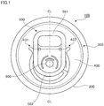
- FIG. 1 is a top view of a beverage can 100 to which the exemplary embodiment is applied.
- the beverage can 100 includes a container body (can barrel) 200 that is formed in a cylindrical shape and has an aperture at an upper portion and a bottom section at a lower portion, and a can lid 300 that is attached to the aperture of the container body 200 to cover the aperture of the container body 200.
- the beverage can 100 is filled with (contains) a drink (contents), such as a soft drink, a carbonated drink or an alcoholic beverage.
- the can lid 300 includes a panel 400 that is formed into a disk shape and functions as a substrate. Moreover, the can lid 300 includes a tab 500 to be operated by a user. Here, the tab 500 is attached to the panel 400. In addition, the tab 500 is arranged along one direction from a peripheral edge section side of the panel 400 toward a rivet 900.
- the tab 500 includes a first edge section 501 on one end section side in the longitudinal direction thereof and a second edge section 502 on the other end section side in the longitudinal direction, and, by user's operation such that the first edge section 501 side is moved in a direction away from the panel 400, the second edge section 502 is pressed against a predetermined location of the panel 400 (to be described in detail later), to thereby press the panel 400.
- the can lid 300 in the exemplary embodiment is a can lid of a so-called stay-on type, in which the tab 500 maintains a state of being attached to the panel 400 even after the opening that functions as a place a person drinks from is formed on the panel 400.
- the tab 500 is fastened to the panel 400 by the rivet 900 provided at a position deviated from a center section (center) of the panel 400.
- the tab 500 is fastened to the panel 400 by the rivet 900 provided in a decentered state with respect to the panel 400.
- the tab 500 is fastened to the panel 400 by the rivet 900 provided closer to the center section of the panel 400 than the location of the panel 400 pressed by the tab 500.
- a portion positioned between the first edge section 501 and the second edge section 502 of the tab 500 is fastened to the panel 400 by the rivet 900.
- the location where the rivet 900 is provided is able to be grasped as a connecting section that connects the portion positioned between the first edge section 501 and the second edge section 502 of the tab 500 and the panel 400.
- the rivet 900 connects a portion positioned on a center line CL of the tab 500 (a virtual center line CL extending from the first edge section 501 side toward the second edge section 502 side along the longitudinal direction of the tab 500) and the panel 400.
- the tab 500 in which the second edge section 502 (a tip end section of the tab 500 (a tab nose)) was formed in a circular arc shape was exemplified; however, for example, it may be possible that the tab 500 is formed in a rectangular shape and the tip end section of the tab 500 is formed in a linear fashion.
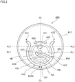
- FIG. 2 is a front view showing a state of the panel 400 before the tab 500 is attached.
- the panel 400 is formed in a disk shape, as described above. Moreover, the panel 400 has an outer peripheral edge 410 in which bending was applied. In the exemplary embodiment, in a state where the outer peripheral edge 410 and an upper edge section (not shown) of the container body 200 are brought into contact with each other, so-called seaming processing is applied to the outer peripheral edge 410 and the upper edge section. This fastens the panel 400 to the upper edge section of the container body 200. Moreover, in the panel 400, a protruding section (nipple) 420, which will be crushed when the tab 500 is fastened to the panel 400 to become the above-described rivet 900, is formed. The protruding section 420 is provided at a location deviated from the center section CP of the panel 400.
- a first score line 430 is formed on a surface of the panel 400.
- the first score line 430 is formed to enclose a region RA, of the panel 400, pressed by the tab 500 (a pressed portion pressed by the tab 500).
- the first score line 430 is formed around the region RA.
- the first score line 430 is configured with a groove formed on the surface of the panel 400 and plays a role of inducing breakage of the panel 400 (to be described later).
- the first score line 430 is able to be grasped as a breakage prediction line on which breakage of the panel 400 is predicted.
- the first score line 430 is formed to curve toward the outer peripheral edge 410 of the panel 400, and is formed in substantially a U shape when the panel 400 is viewed from the front. Further, the first score line 430 includes one end section 431 and the other end section 432 on the center section CP side of the panel 400, and a vertex section 433A on the outer peripheral edge 410 side of the panel 400.
- the one end section 431 of the first score line 430 is arranged on one side of two regions that face each other with the center line CL (also refer to FIG. 1 ) of the tab 500 interposed therebetween.
- the one end section 431 is arranged on one side of two regions that face each other with the center line CL along the longitudinal direction of the tab 500 interposed therebetween.
- the other end section 432 is arranged on the other side of two regions that face each other with the center line CL interposed therebetween.
- the first score line 430 is arranged to be linearly symmetric with respect to the center line CL of the tab 500 as a symmetrical axis.
- the one end section 431 and the other end section 432 in a state of being separated from each other, between the one end section 431 and the other end section 432, there is generated a state providing a discontinuous section where the first score line 430 is not provided.
- a later-described tongue section is not separated from the panel 400, and the tongue section is in a state of attaching to the panel 400.
- the center line CL of the tab 500 passes through the center section CP of the panel 400 and the protruding section 420 formed on the panel 400, as shown in FIG. 2 .
- the above-described one end section 431 and the other end section 432 are provided closer to the center section CP side of the panel 400 than the first virtual line KL1.
- the one end section 431 and the other end section 432 are provided upward of the rivet 900.
- the vertex section 433A is provided in one of two regions that face each other with a second virtual line KL2, which is a virtual line that is orthogonal to the above-described center line CL and passes through the center section CP of the panel 400, interposed therebetween, and the one end section 431 and the other end section 432 are provided in the other region. Further, in the one region, the protruding section 420 is provided.
- the protruding section 420 that will become the rivet 900 is provided in a portion of the panel 400 enclosed by the first score line 430, which is positioned closer to the vertex section 433A side than the one end section 431 and the other end section 432 of the first score line 430.
- the first score line 430 includes a curved section 433.
- the curved section 433 is provided to connect the one end section 431 and the other end section 432, swell toward a side on which the protruding section 420 is provided, and pass through closer to the outer peripheral edge 410 side of the panel than the protruding section 420.
- the curved section 433 has the vertex section 433A at a location crossing the center line CL.
- a reinforcing bead HB that increases stiffness of the region enclosed by the first score line 430 is formed.
- an embossment EB which protrudes upward (outward of the beverage can 100) and is pressed by the tip end of the tab 500, is provided.
- the region enclosed by the first score line 430 is pressed by the tab 500, and accordingly, breakage of the panel 400 is caused on the location where the first score line 430 is formed (to be described in detail later).
- the above-described tongue-shaped portion formed by breakage caused on the first score line 430 is referred to as a tongue section, in some cases.
- the second score line 450 is formed on the surface of the panel 400 . It should be noted that the second score line 450 is also configured with a groove formed on the surface of the panel 400 and plays a role of inducing breakage of the panel 400. Of the two regions facing each other with the first virtual line KL1 interposed therebetween, the second score line 450 is provided in the region where the vertex section 433A (the vertex section 433A of the first score line 430) is provided.
- the second score line 450 includes one end section 451 and the other end section 452.
- the other end section 452 of the second score line 450 is connected to the curved section 433 of the first score line 430.
- the score line branches at a location where the first score line 430 and the second score line 450 are connected.
- the other end section 452 of the second score line 450 is connected to a portion positioned between the center line CL and the first virtual line KL1 in the curved section 433 of the first score line 430.
- the other end section 452 of the second score line 450 is connected to a portion positioned between the vertex section 433A and the other end section 432 of the first score line 430.
- the other end section 452 of the second score line 450 is connected to, of the first score line 430, a location other than the location where the vertex section 433A is provided.
- the connecting section of the first score line 430 and the second score line 450 is provided at a location other than a crossing location KP where the center line CL and the first score line 430 cross each other.
- the second score line 450 is provided to head toward the inside of the region enclosed by the first score line 430 from the connecting section with the first score line 430.
- the connecting section of the first score line 430 and the second score line 450 is provided closer to a side where the above-described crossing location KP is provided than the first virtual line KL1 arranged in a relation orthogonal to the center line CL.
- the connecting section of the first score line 430 and the second score line 450 is provided closer to a side where the region RA is positioned than the first virtual line KL1 arranged in a relation orthogonal to the center line CL.
- the distance between the connecting section 490 of the first score line 430 and the second score line 450 and the one end section 431 of the first score line 430 is larger than the distance between the connecting section and the other end section 432 of the first score line 430.
- the length of the portion positioned between the one end section 431 of the first score line 430 and the above-described connecting section is longer than the length of the portion positioned between the other end section 432 of the first score line 430 and the above-described connecting section.
- the second score line 450 is connected to a portion positioned between the vertex section 433A and the one end section 431 of the first score line 430.
- the one end section 451 of the second score line 450 is provided in proximity to the protruding section 420.
- the one end section 451 of the second score line 450 is arranged in one of the two regions facing with the centerline CL interposed therebetween, and the other end section 452 of the second score line 450 is arranged in the other one of the two regions.
- the second score line 450 includes a linear section 453 heading for the protruding section 420 from the other end section 452.
- the second score line 450 includes a curved section 454.
- the curved section 454 is arranged to be connected to the linear section 453, and have a distance with the protruding section 420 formed into a circular-cylindrical shape, and is provided to be along the protruding section 420.
- the curved section 454 is formed between the protruding section 420 and the first score line 430.
- the curved section 454 is formed between the vertex section 433A of the first score line 430 and the protruding section 420.
- the curved section 454 of the second score line 450 is arranged between the protruding section 420 and the first score line 430.
- the curved section 454 is provided to pass between the region RA, of the panel 400, pressed by the tab 500 (the pressed portion pressed by the tab 500) and the protruding section 420.
- the second score line 450 is provided to pass through closer to a side where the protruding section 420 (the rivet 900) is provided than the above-described region RA, and also the second score line 450 is provided to pass between the above-described region RA and the protruding section 420.
- the curved section 454 of the second score line 450 is provided to cross the above-described center line CL that passes through the region RA, which is pressed by the tab 500, and the protruding section 420 (the straight line passing through the region RA and the protruding section 420).
- the second score line 450 in the exemplary embodiment after passing between the region RA and the protruding section 420, travels along the direction crossing the center line CL, and is connected to the first score line 430.
- the second score line 450 in the exemplary embodiment is formed along the direction that crosses the direction of providing the center line CL.
- the second score line 450 traveling in the direction crossing the center line CL travels to gradually approach the side on which the region RA is positioned, of the side on which the region RA is positioned and the side on which the protruding section 420 is provided. More specifically, the second score line 450 travels toward the first score line 430 so that the linear section 453 of the second score line 450 gradually approaches the side on which the region RA is positioned.
- the second score line 450 after passing between the region RA and the protruding section 420, travels to be gradually separated from the first virtual line KL1, and is connected to the first score line 430. It should be noted that, at this time, the second score line 450 passes beside the region RA. To additionally describe, the second score line 450, after passing between the region RA and the protruding section 420, travels to be gradually separated from the first virtual line KL1, which is a straight line orthogonal to the straight line passing the vertex section 433A of the first score line 430 and the center section CP of the panel 400 and is a straight line passing through the protruding section 420, travels aside the region RA, and is connected to the first score line 430.
- KL1 is a straight line orthogonal to the straight line passing the vertex section 433A of the first score line 430 and the center section CP of the panel 400 and is a straight line passing through the protruding section 420
- FIGS. 3A to 3E a diagram for illustrating the states of the panel 400
- the states of the panel 400 when the tab 500 is operated will be described. It should be noted that, in each of FIGS. 3A to 3E , the diagram viewing the panel 400 from the front is shown. Moreover, in each of FIGS. 3A to 3E , illustration of the tab 500 is omitted.
- the second edge section 502 of the tab 500 presses the above-described region RA (refer to FIG. 2 ) positioned between the curved section 454 of the second score line 450 and the vertex section 433A of the first score line 430. Then, when the region RA is pressed by the tab 500, first, breakage of the panel 400 is caused on the curved section 454 of the second score line 450 provided to pass between the region RA and the rivet 900 (the protruding section 420) (refer to FIG. 3B ). Thereafter, in the exemplary embodiment, breakage of the panel 400 proceeds along the second score line 450, and there is generated a state in which the panel 400 is broken to the connecting section of the first score line 430 and the second score line 450.
- the score line branches at the above-described connecting section of the first score line 430 and the second score line 450. Accordingly, after breakage of the panel 400 proceeded from the above-described curved section 454 of the second score line 450 to the above-described connecting section, in the exemplary embodiment, as shown in FIG. 3C , breakage heading for the one end section 431 of the first score line 430 from the connecting section proceeds. Moreover, as shown in FIG. 3D , breakage heading for the other end section 432 of the first score line 430 from the connecting section also proceeds.
- the rear end section of the tab 500 is further pulled up by the user, and thereby breakage of the panel 400 to the one end section 431 and the other end section 432 of the first score line 430 further proceeds.
- the tongue section is bent at a basal part of the tongue section (the location positioned between the one end section 431 and the other end section 432 of the first score line 430), and as shown in FIG. 3E , the tongue section enters into the inside of the beverage can 100. Consequently, in the beverage can 100, an opening that functions as a place a person drinks from is formed. It should be noted that, although detailed description will be given later, when the pulled-up tab 500 is returned to the original state, the tab 500 is bent.
- FIG. 4 a diagram for illustrating breakage caused in the panel 400.
- the above-described region RA (refer to FIG. 2 ) positioned between the curved section 454 of the second score line 450 and the vertex section 433A of the first score line 430 is pressed by the tab 500.
- the region positioned on a side of the vertex section 433A of the first score line 430 than the second score line 450 is pressed by the tab 500. This causes, first, breakage of the panel 400 at the curved section 454 of the second score line 450. Thereafter, breakage of the panel 400 proceeds along the second score line 450, and then breakage proceeds to the connecting section 490 of the first score line 430 and the second score line 450.
- breakage of the panel 400 proceeds along the first score line 430, to thereby bring into a state in which breakage of the panel 400 is caused to the location indicated by the reference sign 4C in FIG. 4 .
- a small opening (hereinafter, referred to as a small opening) is formed in part of the panel 400.
- the tab 500 inters into the inside of the beverage can 100 through the above-described small opening. Then, at this time, the tab 500 comes to press the location indicated by the reference sign 4E in FIG. 4 . To additionally describe, the edge section of the small opening is pressed. To describe further, of the panel 400, a region 4B positioned above the location where the second score line 450 comes to be pressed. To describe further, a region positioned between the location of the first score line 430 positioned closer to the other end section 432 side than the above-described connecting section and the second score line 450 comes to be pressed by the tab 500.
- breakage of the panel 400 proceeds along the first score line 430, and the panel 400 is broken to the location indicated by the reference sign 4D.
- breakage of the panel 400 is caused to the vicinity of the location where the first virtual line KL1 (refer to FIG. 2 ) that passes through the protruding section 420 and the first score line 430 cross each other.
- breakage of the panel 400 is caused in the portion of the first score line 430 positioned closer to the other end section 432 side than the above-described connecting section, and the panel 400 is broken to the location indicated by the reference sign 4D.
- breakage of the panel 400 is further caused on the first score line 430. Specifically, breakage of the panel 400 is caused in both of a first portion of the first score line 430 positioned between the above-described location indicated by the reference sign 4C and the one end section 431 and a second portion of the first score line 430 positioned between the above-described location indicated by the reference sign 4D and the other end section 432.
- the tongue section is bent at a basal part of the tongue section (the location positioned between the one end section 431 and the other end section 432 of the first score line 430), and as shown in FIG. 3E , the tongue section enters into the inside of the beverage can 100. Consequently, in the beverage can 100, the opening is formed.
- the first score line 430 is arranged in linearly symmetrical relation with respect to the center line CL as a symmetrical axis. Therefore, breakage of the panel 400 from the location indicated by the reference sign 4C toward the one end section 431 and breakage of the panel 400 from the location indicated by the reference sign 4D toward the other end section 432 are caused at substantially a same timing. To additionally describe, breakage of the panel 400 from the location indicated by the reference sign 4C toward the one end section 431 and breakage of the panel 400 from the location indicated by the reference sign 4D toward the other end section 432 proceed simultaneously.
- breakage of the panel 400 is caused on the second score line 450, first.
- breakage of the panel 400 is caused at the portion of the first score line 430 positioned between the above-described connecting section and the location indicated by the reference sign 4C.
- breakage of the panel 400 is caused at the portion of the first score line 430 positioned between the above-described connecting section and the location indicated by the reference sign 4D.
- breakage of the panel 400 from the above-described connecting section toward the one end section 431 of the first score line 430 and breakage of the panel 400 from the above-described connecting section toward the other end section 432 of the first score line 430 are not caused simultaneously, but breakage of the panel 400 is caused in a temporally-shifted state.
- the connecting section of the first score line 430 and the second score line 450 is not positioned on the center line CL of the tab 500, and the connecting section of the first score line 430 and the second score line 450 is positioned at a position deviated from the center line CL. Accordingly, breakage of the panel 400 from the connecting section toward the one end section 431 of the first score line 430 and breakage of the panel 400 from the connecting section toward the other end section 432 of the first score line 430 are not caused simultaneously, but breakage of the panel 400 is caused in a temporally-shifted state.
- breakage from the connecting section toward the one end section 431 is caused first, and breakage from the connecting section toward the other end section 432 is next caused. Accordingly, in the exemplary embodiment, as compared to a case where breakage of the panel 400 toward the one end section 431 and breakage of the panel 400 toward the other end section 432 are caused simultaneously, an operation load on the tab 500 when the opening is formed in the panel 400 is reduced.
- the tip end section presses a portion positioned below the second score line 450 (a portion positioned closer to the vertex section 433A than the second score line 450), but does not press a portion positioned above the second score line 450.
- the exemplary embodiment does not have a configuration in which both of the portion positioned below the second score line 450 and the portion positioned above the second score line 450 are simultaneously pressed by the tab 500, but has a configuration in which the tab 500 contacts the portion positioned below the second score line 450 only, and thereby only this portion is pressed by the tab 500.
- the above-described region 4B and the tab 500 are configured to be brought into contact after the above-described small opening is formed in the panel 400.
- breakage of the panel 400 from the above-described connecting section toward the one end section 431 of the first score line 430 and breakage of the panel 400 from the above-described connecting section toward the other end section 432 of the first score line 430 are not caused simultaneously, but breakage of the panel 400 is caused in a temporally-shifted state. This reduces the operation load on the tab 500 when the tab 500 is pulled up, as compared to the case where breakage of the panel 400 is caused at the same time.
- breakage of the panel 400 from the location indicated by the reference sign 4C toward the one end section 431 and breakage of the panel 400 from the location indicated by the reference sign 4D toward the other end section 432 are caused at substantially a same timing.
- the angle of the tab 500 with respect to the panel 400 becomes large. Therefore, in this case, the operation load on the tab 500 does not become so large, and accordingly, degradation in operability of the tab 500 is suppressed.
- a groove 600 is provided in the region positioned between the one end section 431 and the other end section 432 of the first score line 430, though description thereof was omitted above.
- the groove 600 is formed to be curved to draw a circular arc, and is provided to head from the side on which the one end section 431 of the first score line 430 is provided toward the side on which the other end section 432 of the first score line 430 is provided. Consequently, in the beverage can 100 in the exemplary embodiment, bending of the tongue section is likely to occur. Moreover, in the exemplary embodiment, since the groove 600 is formed to be curved, the tongue section having been bent is hardly returned to the original state.
- groove 600 may have any one of the shapes shown in FIGS. 5A to 5D .
- FIGS. 5A to 5D are diagrams showing other examples of the shape of the groove 600.
- the groove 600 is, for example, as shown in FIG. 5A , able to be formed into a shape including a first side surface 621 and a second side surface 622 having a relation of substantially being orthogonal to the surface of the panel 400, and a flat bottom surface 623 connecting the first side surface 621 and the second side surface 622.
- a bottom section of the groove 600 may be assigned with curvature as shown in FIG. 5B .
- the groove 600 is able to be formed into a shape having a triangular cross section as shown in FIG. 5C .
- stiffness of the basal part of the tongue section is decreased by forming the groove 600; however, as shown in FIG. 5D , the stiffness may be decreased by applying bending processing to the basal part of the tongue section.
- the groove 600 was formed to curve toward a side opposite to the side where the protruding section 420 is provided; however, the groove 600 may be formed to curve toward the side where the protruding section 420 is provided. It should be noted that, in the exemplary embodiment, the description was given to a mode in which the groove 600 was provided; however, the groove 600 is not necessarily required, and the groove 600 may be omitted.
- the mode of arranging the second score line 450 is not limited to the mode like this.
- FIG. 6 a diagram showing another configuration example of the panel 400
- a second score line 450 that does not pass between the region RA and the protruding section 420 may be provided.
- the second score line 450 is depicted as substantially a straight line; however, the second score line 450 is not limited to the straight line, but may be a curved line or other line.
- FIGS. 7A to 7D are diagrams for illustrating a configuration of the tab 500.
- FIGS. 8A to 8D are diagram showing movement of the tab 500 when the opening is formed in the beverage can 100. It should be noted that FIG. 7A is a front view of the tab 500 and FIG. 7B is a perspective view of the tab 500.
- the tab 500 in the exemplary embodiment includes, as shown in FIGS. 7A and 7B , a tab main body section 520 that is formed into a rectangular shape and a plate-like shape.
- bending processing (curling processing) is applied to an outer peripheral edge of the tab main body section 520, and accordingly, the outer peripheral edge of the tab main body section 520 is in a state of curling into the inside.
- curling sections are formed at the edge section provided all around the tab main body section 520. Consequently, in the tab 500 in the exemplary embodiment, bending stiffness is increased.
- the shape of the cross section of the bending processing in the outer peripheral edge of the tab 500 is not limited to substantially a circular shape, as in the exemplary embodiment; however, the shape may be an elliptic, rectangular, triangular or polygonal shape.
- a through hole (a finger hole) 530 in which user's finger is caught is formed on a side (a tab tail side) opposite to the side on which the second edge section 502 that presses the panel 400 is provided. It should be noted that the through hole 530 is able to be omitted.
- an insertion hole 540 into which the protruding section 420 (refer to FIG. 2 ) provided in the panel 400 is inserted is formed on the tip end section side (the second edge section side 502) of the tab 500.
- a first curling section slit 521 is formed in the exemplary embodiment.
- the tab 500 of the exemplary embodiment includes a first side edge 503 formed to head from the first edge section 501 toward the second edge section 502, and a second side edge 504 that is formed to similarly head from the first edge section 501 toward the second edge section 502 and is arranged on a side opposite to the first side edge 503, and in the exemplary embodiment, in the curling section provided along the second side edge 504, the first curling section slit 521 is formed.
- a second curling section slit 522 is formed in another curling section provided along the longitudinal direction of the tab 500.
- the second curling section slit 522 is formed in the another curling section provided along the first side edge 503, the second curling section slit 522 is formed.
- a groove 523 is formed. Moreover, on the location where an end section of the first curling section slit 521 is positioned and the location where an end section of the second curling section slit 522 is positioned, punching processing in a circular shape is applied to relief concentration of stress.
- the first curling section slit 521, the second curling section slit 522 and the groove 523 are provided in a state along the short direction of the tab 500. Moreover, the first curling section slit 521, the second curling section slit 522 and the groove 523 are arranged to be on the same straight line. In addition, the first curling section slit 521, the second curling section slit 522 and the groove 523 are arranged between the insertion hole 540 and the through hole 530.
- the first curling section slit 521, the second curling section slit 522 and the groove 523 are formed in this manner, and accordingly, stiffness (bending stiffness) in the portions where these are formed is decreased.
- the tab 500 when the tab 500 is pulled up to form the opening in the panel 400, the tab 500 begins to be bent at a portion of the tab main body section 520 between the first curling section slit 521 and the second curling section slit 522; however, since the curling sections facing in the first curling section slit 521 and the second curling section slit 522 endure the above-described loads in the compressing direction, the bending is inhibited, and thereby the bending stiffness in the longitudinal direction of the tab 500 is secured, and the tab 500 is escaped being bent. As a result, the second edge section 502 side of the tab 500 presses the panel 400, to thereby form the opening in the panel 400.
- the pulled-up tab 500 stands substantially in the vertical direction to the panel 400, and the first edge section 501 side of the tab 500 is brought into a state of protruding from the top surface of the panel 400. Consequently, if a load in a direction of returning to the first edge section 501 side of the tab 500 in order to bend the first edge section 501 side in a direction opposite to the above-described pulling-up direction, bending is to start from a portion of the tab main body section 520 that connects the first curling section slit 521 and the second curling section slit 522.
- the tab 500 begins to be bent at the portion of the tab main body section 520 between the first curling section slit 521 and the second curling section slit 522. At this time, if the groove 523 has been formed, the above-described bending is likely to be made further.
- the tab 500 if a load is applied to the rear end section side of the tab 500, the tab 500 is bent. Accordingly, in the exemplary embodiment, when the tab 500 pulled up by a user is operated to be returned to the original state, the tab 500 is bent, to thereby maintain a state in which the tip end section side of the tab 500 is inserted into the inside of the beverage can 100.
- the groove 523 is formed between the first curling section slit 521 and the second curling section slit 522 to decrease the stiffness in the portion; however, the stiffness is able to be decreased not only by forming such a groove, but also by applying the bending processing. Moreover, the groove 523 is not necessarily required, and the groove 523 may be omitted.
- a first main body section slit 731 to a third main body section slit 733 are provided to penetrate through the tab main body section 520.
- the first main body section slit 731 to the third main body section slit 733 are formed to draw circular arcs along an outer peripheral edge of the insertion hole 540 that has been formed into a circular shape.
- the first main body section slit 731 to the third main body section slit 733 are formed to draw the circular arcs around the location where the insertion hole 540 is provided (the location of the tab 500 connected to the panel 400).
- the shape of the first main body section slit 731 to the third main body section slit 733 is not limited to the circular arc shape. As necessary, the shape may be other than the circular arc, as shown in FIGS. 7C and 7D .
- each of the second main body section slit 732 and the third main body section slit 733 is configured with a first linear section 91 and a second linear section 92.
- the first linear section 91 is formed along the longitudinal direction of the tab 500
- the second linear section 92 is formed along the short direction of the tab 500.
- the first main body section slit 731 is configured with a first linear section 93, a second linear section 94 and a third linear section 95.
- the first linear section 93 and the second linear section 94 are formed along the longitudinal direction of the tab 500.
- the third linear section 95 is formed along the short direction of the tab 500, and connects the first linear section 93 and the second linear section 94.
- FIG. 7D similar to FIG. 7C , the first linear section 91 and the second linear section 92 are provided; however, in FIG. 7D , the second linear section 92 is arranged in a state of being inclined with respect to the longitudinal direction and the short direction of the tab 500.
- the third linear section 95 (refer to FIG. 7C ) is omitted, and the first linear section 93 and the second linear section 94 are arranged in a state of being inclined with respect to the longitudinal direction and the short direction of the tab 500.
- the first main body section slit 731 is provided on a side closer to the insertion hole 540 than the second main body section slit 732, as an example of a second through hole
- the first main body section slit 731 is provided on a side closer to the insertion hole 540 than the third main body section slit 733, as an example of a third through hole.
- the second main body section slit 732 and the third main body section slit 733 are formed to draw circular arcs along the outer peripheral edge of the insertion hole 540, as described above, and provided to pass through locations that are in the same distance from the insertion hole 540. It should be noted that the same is true for the first main body section slit 731, and thereby the first main body section slit 731 is provided to pass through locations that are in the same distance from the insertion hole 540.
- the first main body section slit 731 is provided closer on the rear end section side (the first edge section 501 side) of the tab 500 than the insertion hole 540. To additionally describe, the first main body section slit 731 is provided between the first edge section 501 and the insertion hole 540 of the tab 500.
- each of the second main body section slit 732 and the third main body section slit 733 includes one end 751 and the other end 752.
- the one end 751 is positioned closer to the second edge section 502 side of the tab 500 than the insertion hole 540.
- the other end 752 is positioned closer to the first edge section 501 side of the tab 500 than the insertion hole 540.
- the other end 752 is arranged at a position heading for the center line CL (also refer to FIG. 1 ) between the first main body section slit 731 and the first edge section 501 of the tab 500.
- the other end 752 is provided in a region positioned between the first main body section slit 731 and the first edge section 501 of the tab 500.
- the second main body section slit 732 is formed to pass beside one of the insertion hole 540 and the first main body section slit 731 from the location where the above-described one end 751 is positioned, and to head for, between the first main body section slit 731 and the first edge section 501 of the tab 500, the center line CL of the tab 500.
- the second main body section slit 732 is formed to pass between the insertion hole 540 and the first side edge 503 of the tab 500 from the location where the above-described one end 751 is positioned, and between the first main body section slit 731 and the first side edge 503 of the tab 500, to head for the first edge section 501 side of the tab 500, and also head for the second side edge 504 side of the tab 500.
- the third main body section slit 733 is also formed to pass beside one of the insertion hole 540 and the first main body section slit 731 from the location where the above-described one end 751 is positioned, and to head for, between the first main body section slit 731 and the first edge section 501 of the tab 500, the center line CL of the tab 500.
- the third main body section slit 733 is formed to pass between the insertion hole 540 and the second side edge 504 of the tab 500 from the location where the above-described one end 751 is positioned, and between the first main body section slit 731 and the second side edge 504 of the tab 500, to head for the first edge section 501 side of the tab 500, and also head for the first side edge 503 side of the tab 500.
- the other ends 752 are positioned between the first main body section slit 731 and the first edge section 501 of the tab 500 to head for the center line CL of the tab 500, and the second main body section slit 732 and the third main body section slit 733 are in a state of extending between the first main body section slit 731 and the first edge section 501 of the tab 500 toward the center line CL of the tab 500 from the above-described one ends 751 as starting points.
- each of the second main body section slit 732 and the third main body section slit 733 formed to draw circular arcs is provided to pass through a location where the distance from the insertion hole 540 becomes larger than the first main body section slit 731, and extends between the first main body section slit 731 and the first edge section 501 to a region approaching the center line CL of the tab 500.
- each of the second main body section slit 732 and the third main body section slit 733 is provided to pass through a location separated by a predetermined separation distance from the insertion hole 540 and to pass through a location where the separation distance becomes larger than the distance between the first main body section slit 731 and the insertion hole 540, and extends between the first main body section slit 731 and the first edge section 501 to a region approaching the center line CL of the tab 500.
- the first main body section slit 731 is provided on the center line CL of the tab 500 (also refer to FIG. 1 ), and is formed into a shape that is linear symmetry with respect to the center line CL as the symmetrical axis.
- the second main body section slit 732 is arranged in one side of two regions facing each other with the center line CL of the tab 500 interposed therebetween, and the third main body section slit 733 is arranged in the other region side.
- the second main body section slit 732 and the third main body section slit 733 are arranged in a relation of linear symmetry with respect to the center line CL of the tab 500 as the symmetrical axis.
- the first main body section slit 731 is formed in a shape of linear symmetry and the second main body section slit 732 and the third main body section slit 733 are provided in a relation of linear symmetry in this manner, when the tab 500 is pulled up by a user, inclination of the tab 500 is suppressed. To describe more specifically, inclination of the tab 500, in which one end section side in the short direction of the tab 500 is positioned above the other end section side, hardly occurs.
- the other end 752 of the second main body section slit 732 and the other end 752 of the third main body section slit 733 are not connected. Consequently, in the exemplary embodiment, between the other end 752 of the second main body section slit 732 and the other end 752 of the third main body section slit 733, an intervening section 728 configured with the tab main body section 520 and intervening between the other end 752 of the second main body section slit 732 and the other end 752 of the third main body section slit 733 is provided.
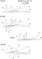
- FIGS. 8A to 8D With reference to FIGS. 8A to 8D , movement of the tab 500 will be described. It should be noted that, in FIGS. 8A to 8D , states of cross section of the tab 500 at the center line CL (refer to FIG. 1 ) are shown.
- a user's finger is inserted between the rear end section of the tab 500 and the panel 400, and the rear end section of the tab 500 is pulled up as shown in FIGS. 8A and 8B .
- the rear end section side of the tab 500 is floated above the panel 400.
- the tip end section side of the tab 500 except for the tip end that is in contact with the panel 400 is also floated above the panel 400. This is because, as shown in FIG. 7A and FIG.
- the region indicated by the reference sign 7D was less susceptible to restraint by the insertion hole 540, and since the other end sections of the second main body section slit 732 and the third main body section slit 733 extended between the first main body section slit 731 and the first edge section 501 side to the region heading for the center line CL of the tab 500, the region indicated by the reference sign 7D was given flexibility in deformation, and by pulling up the rear end section of the tab 500, the intervening section 728 shown in FIG.
- a shearing force comes to act on the second score line 450 provided to pass between the tip end section of the tab 500 and the rivet 900. Then, by the shearing force, at the location where the second score line 450 is provided, breakage of the panel 400 is caused. Then, by further performing pulling up of the rear end section of the tab 500, breakage of the panel 400 is also caused on the first score line 430 as described above.
- the one end 751 provided to each of the second main body section slit 732 and the third main body section slit 733 is positioned closer to the tip end section side of the tab 500 than the insertion hole 540. Then, in this case, the region positioned between the one ends 751 and the insertion hole 540 (the region 7A indicated by oblique lines in FIG. 7A ) is floated above the panel 400 as indicated by reference sign 8A in FIG. 8B , when pulling up of the tab 500 is started. Then, the tip end section side except for the tip end of the tab 500 is floated above the panel 400, and accordingly, the whole tab 500 becomes inclined to the panel 400.
- the tip end section side of the tab 500 is hardly floated above the panel, and accordingly, the rear end section side of the tab 500 is hardly floated above the panel 400, too. Then, in this case, the user's finger is less likely to be inserted between the tab 500 and the panel 400, and thereby operability of the tab 500 is prone to be decreased.
- the load from the tab 500 (the operation load from the user) is less likely to be transmitted to the rear end section side of the rivet 900 in the state of FIG. 8B .
- a force to pull up the rear end section side of the rivet 900 (of the rivet 900, the portion positioned closer to the first edge section 501 side of the tab 500) upward in the figure is less likely to act on the rivet 900.
- breakage of the panel 400 on the second score line 450 is able to be caused with more efficiency; however, if the load comes to act more on the rear end section side of the rivet 900, the load comes to act on a location distant from the second score line 450 (the operation load from the user is distributed), the breakage of the panel 400 on the second score line 450 is less likely to be caused.
- the operation load from the user transmitted to the rear end section of the rivet 900.
- the operation force from the user comes to act on the tip end section side of the rivet 900 intensively (the operation load from the user comes to intensively act on a location, which is closer to the second score line 450), the breakage of the panel 400 on the second score line 450 is likely to be caused. Then, in this case, the user is able to cause the breakage of the panel 400 with less operation load.
- breakage of the panel 400 further proceeds toward the basal part of the tongue section (toward the one end section 431 (refer to FIG. 4 ) and the other end section 432 of the first score line 430).
- breakage of the panel 400 is caused in both of the first portion positioned between the above-described location indicated by the reference sign 4C and the one end section 431, and the second portion positioned between the above-described location indicated by the reference sign 4D and the other end section 432.
- FIG. 8C shows a state of the tab 500 when breakage of the panel 400 is caused in both of the above-described first portion and the above-described second portion.
- the angle of the tab 500 with respect to the panel 400 is brought into a state of being larger, and the tip end section side of the tab 500 is brought into a state in contact with the panel 400.
- the intervening section 728 starts to move in the direction apart from the panel 400.
- the region indicated by the reference sign 7D starts to move from the intervening section 728 in the direction gradually apart from the panel 400.
- the region indicated by the reference sign 7D is enclosed by the first main body section slit 731, the second main body section slit 732 and the third main body section slit 733 so as to be less susceptible to restraint from the tab main body section 520, and further, so as to be able to be dependent from the tab main body section 520 and deformable into a unique shape. Consequently, when the intervening section 728 is moved in the direction apart from the panel 400, with this, the region of the reference sign 7D is deformed while being curved so that the periphery of the first main body section slit 731 is left on the panel 400 side, and is further expanded with the intervening section 728 being regarded as a vertex section. As this state, in FIG.
- the force becomes a force to pull up the panel 400 on the right side of the rivet 900.
- a force to press down the panel 400 by the tip end of the tab 500 is acting.
- the rotational moment indicated by arrow 8D comes to act on the panel 400, and by the rotational moment, the tongue section enters into the inside of the beverage can 100.
- breakage of the panel 400 is caused in both of the above-described first portion positioned between the above-described location indicated by the reference sign 4C (refer to FIG. 4 ) and the one end section 431, and the above-described second portion positioned between the above-described location indicated by the reference sign 4D and the other end section 432, and the tongue section enters into the inside of the beverage can 100.
- the load 8B shown in FIG. 8B is mainly a load applied to the tip end section side of the rivet 900 in the course of opening formation in the regions 4A and 4B in FIG. 4 .
- the above-described expansion of the reference sign 7D is stopped, and thereby the tab 500 is brought into a state of being pulled up to have a predetermined inclination.
- the load is mainly applied to the rear end section side of the rivet 900 through the region of the reference sign 7D and the region 7C. In this manner, the rotational moment 8D shown in FIG. 8C comes to act.
- the operation load from the user is transmitted to the rear end section of the rivet 900 by use of the intervening section 728 (refer to FIG. 7A ).
- the intervening section 728 is not provided, to additionally describe, in a case where the second main body section slit 732 and the third main body section slit 733 are connected, the tab 500 is to rotate around a straight line (refer to the straight line indicated by the reference sign 7E in FIG. 7A ) that passes through the one end 751 (refer to FIG. 7A ) of the second main body section slit 732 and the one end 751 of the third main body section slit 733.
- the load applied to the rear end section of the rivet 900 is reduced, and thereby the rotational moment that acts on the above-described tongue section is decreased.
- the other ends 752 of the second main body section slit 732 and the third main body section slit 733 are positioned between the first main body section slit 731 and the first edge section 501 of the tab 500 to head for the center line CL of the tab 500. Consequently, in the exemplary embodiment, there is provided a configuration in which the second main body section slit 732 and the third main body section slit 733 extend between the first main body section slit 731 and the first edge section 501 of the tab 500 to a region heading for the center line CL of the tab 500 from the above-described one ends 751 as the starting points.
- the operation load from the user acts on the rear end section of the rivet 900 through the portion of the region 7C indicated by oblique lines in FIG. 7A .
- the second main body section slit 732 and the third main body section slit 733 extend between the first main body section slit 731 and the first edge section 501 of the tab 500 to head for the center line CL of the tab 500, there is provided a state in which the first main body section slit 731 is positioned between the intervening section 728 that transmits the load from the rear end section side of the tab 500 to the tip end section side of the tab 500 and the rivet 900.
- the second main body section slit 732 and the third main body section slit 733 extend between the first main body section slit 731 and the first edge section 501 of the tab 500 to head for the center line CL of the tab 500
- the first main body section slit 731 that makes the load to the rear end side of the rivet 900 less likely to be transmitted is positioned between the intervening section 728 and the rivet 900.
- the load applied to the rear end side of the rivet 900 when the operation of the tab 500 is started by the user is reduced.
- the load intensively acts on the second score line 450.
- the tip end section of the tab 500 presses the panel 400 to start breakage of the panel 400. Thereafter, breakage of the panel 400 is further caused, and accordingly, the panel 400 is broken to the location of the first score line 430 indicated by the reference sign 4C (refer to FIG. 4 ) and the location of the first score line 430 indicated by the reference sign 4D.
- the load from the tab 500 acts on the tip end section side of the rivet 900.
- the region of the reference sign 7D is observed in FIG. 7A , when the tab 500 is pulled up, the intervening section 728 connected to the tab main body section 520 is lifted. To put another way, by pulling up the tab 500, the region of the reference sign 7D is lifted from the intervening section 728 side. In the region of reference sign 7D at this time, since the intervening section 728, which is one end section, is lifted while both end sections side of the first main body section slit 731, which is the other end section, is left on the panel 400 side, the region of the reference sign 7D expands with curvature deformation while the intervening section 728 being regarded as a vertex section. At this point of time, due to the above-described expansion, the load from the tab 500 is less likely to act on the rear end section side of the rivet 900.
- the load from the tab 500 acts on the tip end section side of the rivet 900 as a reactive force of the press of the panel 400 by the tip end of the tab 500. Thereafter, breakage of the panel 400 further proceeds, and thereby, the panel 400 is broken to the above-described location of the first score line 430 indicated by the reference sign 4C (refer to FIG. 4 ) and the location of the first score line 430 indicated by the reference sign 4D.
- the load from the tab 500 acts on the tip end section side of the rivet 900, and thereby breakage of the panel 400 proceeds.
- the load from the tab 500 is less likely to act on the rear end section side of the rivet 900.
- the region 7D is hardly expanded further, and therefore, the load from the tab 500 is transmitted to the region 7C by way of the region of the reference sign 7D, to thereby act on the rear end section side of the rivet 900.
- the load from the tab 500 mainly acts on the tip end section side of the rivet 900 in substantially the first half of the opening process, and also acts on the rear end section side of the rivet 900 in substantially the second half.
- rotational moment 8D comes to act on the panel 400 around the rivet 900.
- the rotational moment 8D breaks the score that leads to the region of the one end section 431 from the reference sign 4C shown in FIG. 4 and that leads to the other end section 432 from the reference sign 4D and acts to bend the region enclosed by the above-described score and insert thereof into the can, to thereby form the opening in the panel 400.
- FIG. 9A shows a state in which the tab 500 stands up and the panel 400 and the tab 500 are orthogonal. Thereafter, the pulled-up tab 500 is to be returned to the original state by the user, and on this occasion, bending of the tab 500 is caused at the first curling section slit 521 (refer to FIGS. 7A to 7D ), the second curling section slit 522 and the groove 523, which have been described above.
- the rear end section side of the tab 500 lies along the panel 400.
- the tip end section side of the tab 500 is in a state of entering into the inside of the beverage can 100.
- the tip end section side of the tab 500 stays inside of the beverage can 100, and thereby overlapping of the opening and the tab 500 becomes small.
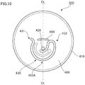
- FIG. 10 a diagram showing another configuration example of the can lid 300
Landscapes
- Engineering & Computer Science (AREA)
- Mechanical Engineering (AREA)
- Ceramic Engineering (AREA)
- Containers Opened By Tearing Frangible Portions (AREA)
Description
- The present invention relates to a can lid and a beverage can.
- A beverage can in which breakage of a panel is caused at a score line by a press of part of the panel by a tab to thereby form an opening that functions as a place a person drinks from is suggested (for example, refer to
JP 51-82188 US 3,501,046 ,FIG.4 , discloses a can barrel and a can lid according to the preamble ofclaim 1. - A beverage can in which breakage of a panel is caused at a score line by a press of part of the panel by a tab to thereby form an opening that functions as a place a person drinks from is known. Here, in such a beverage can, by further operating the tab after the breakage of the panel is caused, a tongue-shaped broken section produced by the breakage of the panel is pressed into the inside of the beverage can, and thereby the opening is formed.
- An object of the present invention is to provide a can lid or the like that is capable of smoothly breaking a panel and smoothly pressing a broken section, which is produced by breakage of the panel, by a tab. Solution to Problem
- A can barrel and a can lid, to which the present invention is applied, includes the features of
claim 1. - Here, the connecting section connects a portion positioned on a center line of the tab and the panel, the portion being positioned on the center line heading for the second edge section side from the first edge section side, the first through hole is provided on the center line of the tab, and formed into a linear symmetrical shape with respect to the center line as a symmetrical axis, and one through hole of the second through hole and the third through hole is formed in one of two regions facing with the center line interposed therebetween, and the other through hole is formed on the other of the two regions, the second through hole and the third through hole being arranged in a linear symmetrical relation with respect to the center line as a symmetrical axis. In this case, it becomes possible to suppress unstable behavior of the tab.
- Moreover, the first through hole is formed to draw a circular arc around a location where the connecting section is provided. In this case, it is possible to make concentration of stress that possibly occurs in the tab less likely to be caused, as compared to a case in which the first through hole is formed to be bent.
- Moreover, the second through hole and the third through hole are formed to draw circular arcs around the location where the connecting section is provided. In this case, it is possible to make concentration of stress that possibly occurs in the tab less likely to be caused, as compared to a case in which the second through hole and the third through hole are formed to be bent.
- Moreover, the second through hole and the third through hole, which are formed to draw the circular arcs, are provided to pass through a location which is separated from the connecting section by a first separation distance, and are formed so that the first separation distance is larger than a separation distance between the first through hole and the connecting section, the second through hole and the third through hole extending to the region positioned between the first through hole and the first edge section. In this case, as compared to a case in which the second through hole and the third through hole do not extend to the region positioned between the first through hole and the first edge section of the tab, it becomes possible to reduce a load, which is applied to a portion of the connecting section positioned on the first edge section side and is applied when operation of the tab is started by the user.
- Moreover, in a case where the present invention is captured as a beverage can, a beverage can, to which the present invention is applied, includes: a can barrel that includes an aperture and contains a beverage inside thereof; and a can lid according to
claim 1. - According to the present invention, it is possible to provide a can lid that is capable of smoothly breaking a panel and smoothly pressing a broken section, which is produced by breakage of the panel, by a tab.
-
-
FIG. 1 is a top view of a beverage can to which an exemplary embodiment of a can lid is applied; -
FIG. 2 is a front view showing a state of a panel before a tab is attached; -
FIGS. 3A to 3E are diagrams for illustrating states of the panel; -
FIG. 4 is a diagram for illustrating breakage caused in the panel; -
FIGS. 5A to 5D are diagrams showing other examples of a shape of a groove; -
FIG. 6 is a diagram showing another configuration example of the panel; -
FIGS. 7A to 7D are diagrams for illustrating a configuration of the tab; -
FIGS. 8A to 8D are diagrams showing movement of the tab when an opening is formed in the beverage can; -
FIGS. 9A and 9B are diagrams in a case where the beverage can is viewed from above; and -
FIG. 10 is a diagram showing another configuration example of a can lid. - Hereinafter, an exemplary embodiment according to the present invention will be described in detail with reference to attached drawings.
-
FIG. 1 is a top view of a beverage can 100 to which the exemplary embodiment is applied. As shown in the figure, the beverage can 100 includes a container body (can barrel) 200 that is formed in a cylindrical shape and has an aperture at an upper portion and a bottom section at a lower portion, and acan lid 300 that is attached to the aperture of thecontainer body 200 to cover the aperture of thecontainer body 200. It should be noted that the beverage can 100 is filled with (contains) a drink (contents), such as a soft drink, a carbonated drink or an alcoholic beverage. - The can
lid 300 includes apanel 400 that is formed into a disk shape and functions as a substrate. Moreover, the canlid 300 includes atab 500 to be operated by a user. Here, thetab 500 is attached to thepanel 400. In addition, thetab 500 is arranged along one direction from a peripheral edge section side of thepanel 400 toward arivet 900. - Moreover, the
tab 500 includes afirst edge section 501 on one end section side in the longitudinal direction thereof and asecond edge section 502 on the other end section side in the longitudinal direction, and, by user's operation such that thefirst edge section 501 side is moved in a direction away from thepanel 400, thesecond edge section 502 is pressed against a predetermined location of the panel 400 (to be described in detail later), to thereby press thepanel 400. It should be noted that the canlid 300 in the exemplary embodiment is a can lid of a so-called stay-on type, in which thetab 500 maintains a state of being attached to thepanel 400 even after the opening that functions as a place a person drinks from is formed on thepanel 400. - Here, in the exemplary embodiment, the
tab 500 is fastened to thepanel 400 by therivet 900 provided at a position deviated from a center section (center) of thepanel 400. To additionally describe, thetab 500 is fastened to thepanel 400 by therivet 900 provided in a decentered state with respect to thepanel 400. To describe further, thetab 500 is fastened to thepanel 400 by therivet 900 provided closer to the center section of thepanel 400 than the location of thepanel 400 pressed by thetab 500. - Further, in the
tab 500, a portion positioned between thefirst edge section 501 and thesecond edge section 502 of thetab 500 is fastened to thepanel 400 by therivet 900. Here, the location where therivet 900 is provided is able to be grasped as a connecting section that connects the portion positioned between thefirst edge section 501 and thesecond edge section 502 of thetab 500 and thepanel 400. Moreover, therivet 900 connects a portion positioned on a center line CL of the tab 500 (a virtual center line CL extending from thefirst edge section 501 side toward thesecond edge section 502 side along the longitudinal direction of the tab 500) and thepanel 400. - Here, in the exemplary embodiment, description is given by taking a mode in which the
tab 500 is fastened to thepanel 400 by therivet 900 provided at the position deviated from the center section of thepanel 400 as an example; however, thetab 500 may be fastened to thepanel 400 by arivet 900 provided at the center section of thepanel 400. Moreover, inFIG. 1 , thetab 500 in which the second edge section 502 (a tip end section of the tab 500 (a tab nose)) was formed in a circular arc shape was exemplified; however, for example, it may be possible that thetab 500 is formed in a rectangular shape and the tip end section of thetab 500 is formed in a linear fashion. -
FIG. 2 is a front view showing a state of thepanel 400 before thetab 500 is attached. - The
panel 400 is formed in a disk shape, as described above. Moreover, thepanel 400 has an outerperipheral edge 410 in which bending was applied. In the exemplary embodiment, in a state where the outerperipheral edge 410 and an upper edge section (not shown) of thecontainer body 200 are brought into contact with each other, so-called seaming processing is applied to the outerperipheral edge 410 and the upper edge section. This fastens thepanel 400 to the upper edge section of thecontainer body 200. Moreover, in thepanel 400, a protruding section (nipple) 420, which will be crushed when thetab 500 is fastened to thepanel 400 to become the above-describedrivet 900, is formed. Theprotruding section 420 is provided at a location deviated from the center section CP of thepanel 400. - Moreover, on a surface of the
panel 400, afirst score line 430 is formed. Thefirst score line 430 is formed to enclose a region RA, of thepanel 400, pressed by the tab 500 (a pressed portion pressed by the tab 500). To additionally describe, thefirst score line 430 is formed around the region RA. Moreover, thefirst score line 430 is configured with a groove formed on the surface of thepanel 400 and plays a role of inducing breakage of the panel 400 (to be described later). To additionally describe, thefirst score line 430 is able to be grasped as a breakage prediction line on which breakage of thepanel 400 is predicted. - Moreover, the
first score line 430 is formed to curve toward the outerperipheral edge 410 of thepanel 400, and is formed in substantially a U shape when thepanel 400 is viewed from the front. Further, thefirst score line 430 includes oneend section 431 and theother end section 432 on the center section CP side of thepanel 400, and avertex section 433A on the outerperipheral edge 410 side of thepanel 400. - The one
end section 431 of thefirst score line 430 is arranged on one side of two regions that face each other with the center line CL (also refer toFIG. 1 ) of thetab 500 interposed therebetween. To additionally describe, the oneend section 431 is arranged on one side of two regions that face each other with the center line CL along the longitudinal direction of thetab 500 interposed therebetween. Moreover, theother end section 432 is arranged on the other side of two regions that face each other with the center line CL interposed therebetween. Moreover, in the exemplary embodiment, thefirst score line 430 is arranged to be linearly symmetric with respect to the center line CL of thetab 500 as a symmetrical axis. - Moreover, in the exemplary embodiment, by arranging the one
end section 431 and theother end section 432 in a state of being separated from each other, between the oneend section 431 and theother end section 432, there is generated a state providing a discontinuous section where thefirst score line 430 is not provided. By providing the discontinuous section, a later-described tongue section is not separated from thepanel 400, and the tongue section is in a state of attaching to thepanel 400. It should be noted that, in the exemplary embodiment, the center line CL of thetab 500 passes through the center section CP of thepanel 400 and the protrudingsection 420 formed on thepanel 400, as shown inFIG. 2 . - In addition, in the exemplary embodiment, in a case where a first virtual line KL1, which is a virtual line that is orthogonal to the above-described center line CL and passes through the protruding section 420 (rivet 900), is assumed, the above-described one
end section 431 and theother end section 432 are provided closer to the center section CP side of thepanel 400 than the first virtual line KL1. To additionally describe, inFIG. 1 , the oneend section 431 and theother end section 432 are provided upward of therivet 900. Moreover, thevertex section 433A is provided in one of two regions that face each other with a second virtual line KL2, which is a virtual line that is orthogonal to the above-described center line CL and passes through the center section CP of thepanel 400, interposed therebetween, and the oneend section 431 and theother end section 432 are provided in the other region. Further, in the one region, the protrudingsection 420 is provided. - To describe further, the protruding
section 420 that will become therivet 900 is provided in a portion of thepanel 400 enclosed by thefirst score line 430, which is positioned closer to thevertex section 433A side than the oneend section 431 and theother end section 432 of thefirst score line 430. Moreover, as shown inFIG. 2 , thefirst score line 430 includes acurved section 433. Thecurved section 433 is provided to connect the oneend section 431 and theother end section 432, swell toward a side on which the protrudingsection 420 is provided, and pass through closer to the outerperipheral edge 410 side of the panel than the protrudingsection 420. - Moreover, the
curved section 433 has thevertex section 433A at a location crossing the center line CL. In addition, in thecan lid 300 in the exemplary embodiment, in the region of thepanel 400 enclosed by thefirst score line 430, a reinforcing bead HB that increases stiffness of the region enclosed by thefirst score line 430 is formed. Moreover, on one end section of the reinforcing bead HB, an embossment EB, which protrudes upward (outward of the beverage can 100) and is pressed by the tip end of thetab 500, is provided. By providing the embossment EB, breakage of thepanel 400 on a second score line 450 (to be described in detail later) is likely to be caused, as compared to a case in which the embossment EB is not provided. - Here, in the exemplary embodiment, by operation of the
tab 500 by a user, the region enclosed by thefirst score line 430 is pressed by thetab 500, and accordingly, breakage of thepanel 400 is caused on the location where thefirst score line 430 is formed (to be described in detail later). This causes the region on which thefirst score line 430 is formed to be in the tongue shape, and also causes the region to be bent toward the inside of the beverage can 100. Consequently, an opening that plays a role of a place a person drinks from is formed in the beverage can 100. It should be noted that, in this specification, hereinafter, the above-described tongue-shaped portion formed by breakage caused on thefirst score line 430 is referred to as a tongue section, in some cases. - Moreover, on the surface of the
panel 400, thesecond score line 450 is formed. It should be noted that thesecond score line 450 is also configured with a groove formed on the surface of thepanel 400 and plays a role of inducing breakage of thepanel 400. Of the two regions facing each other with the first virtual line KL1 interposed therebetween, thesecond score line 450 is provided in the region where thevertex section 433A (thevertex section 433A of the first score line 430) is provided. - Moreover, the
second score line 450 includes oneend section 451 and theother end section 452. Here, theother end section 452 of thesecond score line 450 is connected to thecurved section 433 of thefirst score line 430. Accordingly, in the exemplary embodiment, the score line branches at a location where thefirst score line 430 and thesecond score line 450 are connected. - To describe the
second score line 450 further, theother end section 452 of thesecond score line 450 is connected to a portion positioned between the center line CL and the first virtual line KL1 in thecurved section 433 of thefirst score line 430. To describe further in detail, theother end section 452 of thesecond score line 450 is connected to a portion positioned between thevertex section 433A and theother end section 432 of thefirst score line 430. To describe further, theother end section 452 of thesecond score line 450 is connected to, of thefirst score line 430, a location other than the location where thevertex section 433A is provided. - To describe further, the connecting section of the
first score line 430 and thesecond score line 450 is provided at a location other than a crossing location KP where the center line CL and thefirst score line 430 cross each other. Moreover, in the exemplary embodiment, thesecond score line 450 is provided to head toward the inside of the region enclosed by thefirst score line 430 from the connecting section with thefirst score line 430. Moreover, in the exemplary embodiment, the connecting section of thefirst score line 430 and thesecond score line 450 is provided closer to a side where the above-described crossing location KP is provided than the first virtual line KL1 arranged in a relation orthogonal to the center line CL. To describe further, the connecting section of thefirst score line 430 and thesecond score line 450 is provided closer to a side where the region RA is positioned than the first virtual line KL1 arranged in a relation orthogonal to the center line CL. - Moreover, in the exemplary embodiment, the distance between the connecting
section 490 of thefirst score line 430 and thesecond score line 450 and the oneend section 431 of thefirst score line 430 is larger than the distance between the connecting section and theother end section 432 of thefirst score line 430. To additionally describe, the length of the portion positioned between the oneend section 431 of thefirst score line 430 and the above-described connecting section is longer than the length of the portion positioned between theother end section 432 of thefirst score line 430 and the above-described connecting section. - It should be noted that, in the exemplary embodiment, the description has been given of a case where the
second score line 450 is provided to head in the lower right direction in the figure; however, thesecond score line 450 may be provided to head in the lower left direction in the figure. In this case, thesecond score line 450 is connected to a portion positioned between thevertex section 433A and the oneend section 431 of thefirst score line 430. - On the other hand, the one
end section 451 of thesecond score line 450 is provided in proximity to the protrudingsection 420. To describe further, the oneend section 451 of thesecond score line 450 is arranged in one of the two regions facing with the centerline CL interposed therebetween, and theother end section 452 of thesecond score line 450 is arranged in the other one of the two regions. To describe further, thesecond score line 450 includes alinear section 453 heading for the protrudingsection 420 from theother end section 452. Further, thesecond score line 450 includes acurved section 454. Thecurved section 454 is arranged to be connected to thelinear section 453, and have a distance with the protrudingsection 420 formed into a circular-cylindrical shape, and is provided to be along the protrudingsection 420. - Here, the
curved section 454 is formed between the protrudingsection 420 and thefirst score line 430. To describe in more detail, thecurved section 454 is formed between thevertex section 433A of thefirst score line 430 and the protrudingsection 420. To additionally describe, on the center line CL, thecurved section 454 of thesecond score line 450 is arranged between the protrudingsection 420 and thefirst score line 430. - Moreover, the
curved section 454 is provided to pass between the region RA, of thepanel 400, pressed by the tab 500 (the pressed portion pressed by the tab 500) and the protrudingsection 420. To additionally describe, in the exemplary embodiment, thesecond score line 450 is provided to pass through closer to a side where the protruding section 420 (the rivet 900) is provided than the above-described region RA, and also thesecond score line 450 is provided to pass between the above-described region RA and the protrudingsection 420. - Moreover, in the exemplary embodiment, the
curved section 454 of thesecond score line 450 is provided to cross the above-described center line CL that passes through the region RA, which is pressed by thetab 500, and the protruding section 420 (the straight line passing through the region RA and the protruding section 420). To describe further, thesecond score line 450 in the exemplary embodiment, after passing between the region RA and the protrudingsection 420, travels along the direction crossing the center line CL, and is connected to thefirst score line 430. To additionally describe, thesecond score line 450 in the exemplary embodiment is formed along the direction that crosses the direction of providing the center line CL. - To describe further, the
second score line 450 traveling in the direction crossing the center line CL travels to gradually approach the side on which the region RA is positioned, of the side on which the region RA is positioned and the side on which the protrudingsection 420 is provided. More specifically, thesecond score line 450 travels toward thefirst score line 430 so that thelinear section 453 of thesecond score line 450 gradually approaches the side on which the region RA is positioned. - To describe further, the
second score line 450, after passing between the region RA and the protrudingsection 420, travels to be gradually separated from the first virtual line KL1, and is connected to thefirst score line 430. It should be noted that, at this time, thesecond score line 450 passes beside the region RA. To additionally describe, thesecond score line 450, after passing between the region RA and the protrudingsection 420, travels to be gradually separated from the first virtual line KL1, which is a straight line orthogonal to the straight line passing thevertex section 433A of thefirst score line 430 and the center section CP of thepanel 400 and is a straight line passing through the protrudingsection 420, travels aside the region RA, and is connected to thefirst score line 430. - Here, also with reference to
FIGS. 3A to 3E (a diagram for illustrating the states of the panel 400), the states of thepanel 400 when thetab 500 is operated will be described. It should be noted that, in each ofFIGS. 3A to 3E , the diagram viewing thepanel 400 from the front is shown. Moreover, in each ofFIGS. 3A to 3E , illustration of thetab 500 is omitted. - In the exemplary embodiment, when rear end section of the
tab 500 is pulled up by a user, thesecond edge section 502 of the tab 500 (refer toFIG. 1 ) presses the above-described region RA (refer toFIG. 2 ) positioned between thecurved section 454 of thesecond score line 450 and thevertex section 433A of thefirst score line 430. Then, when the region RA is pressed by thetab 500, first, breakage of thepanel 400 is caused on thecurved section 454 of thesecond score line 450 provided to pass between the region RA and the rivet 900 (the protruding section 420) (refer toFIG. 3B ). Thereafter, in the exemplary embodiment, breakage of thepanel 400 proceeds along thesecond score line 450, and there is generated a state in which thepanel 400 is broken to the connecting section of thefirst score line 430 and thesecond score line 450. - Here, in the exemplary embodiment, the score line branches at the above-described connecting section of the
first score line 430 and thesecond score line 450. Accordingly, after breakage of thepanel 400 proceeded from the above-describedcurved section 454 of thesecond score line 450 to the above-described connecting section, in the exemplary embodiment, as shown inFIG. 3C , breakage heading for the oneend section 431 of thefirst score line 430 from the connecting section proceeds. Moreover, as shown inFIG. 3D , breakage heading for theother end section 432 of thefirst score line 430 from the connecting section also proceeds. - Thereafter, the rear end section of the
tab 500 is further pulled up by the user, and thereby breakage of thepanel 400 to the oneend section 431 and theother end section 432 of thefirst score line 430 further proceeds. This causes the region enclosed by thefirst score line 430 to become the above-described tongue section. In addition, the tongue section is bent at a basal part of the tongue section (the location positioned between the oneend section 431 and theother end section 432 of the first score line 430), and as shown inFIG. 3E , the tongue section enters into the inside of the beverage can 100. Consequently, in the beverage can 100, an opening that functions as a place a person drinks from is formed. It should be noted that, although detailed description will be given later, when the pulled-uptab 500 is returned to the original state, thetab 500 is bent. - Here, breakage of the
panel 400 caused on thefirst score line 430 and thesecond score line 450 will be further described with reference toFIG. 4 (a diagram for illustrating breakage caused in the panel 400). In the exemplary embodiment, as described above, by pulling up the rear end section of thetab 500 by a user, the above-described region RA (refer toFIG. 2 ) positioned between thecurved section 454 of thesecond score line 450 and thevertex section 433A of thefirst score line 430 is pressed by thetab 500. - To additionally describe, of the region enclosed by the
first score line 430, the region positioned on a side of thevertex section 433A of thefirst score line 430 than thesecond score line 450 is pressed by thetab 500. This causes, first, breakage of thepanel 400 at thecurved section 454 of thesecond score line 450. Thereafter, breakage of thepanel 400 proceeds along thesecond score line 450, and then breakage proceeds to the connectingsection 490 of thefirst score line 430 and thesecond score line 450. - Thereafter, by further pressing the region RA (refer to
FIG. 2 ) of thepanel 400 by thesecond edge section 502 of thetab 500, breakage of thepanel 400 proceeds along thefirst score line 430, to thereby bring into a state in which breakage of thepanel 400 is caused to the location indicated by thereference sign 4C inFIG. 4 . To additionally describe, there is caused a state in which breakage of thepanel 400 is caused to the vicinity of the location where the first virtual line KL1 (refer toFIG. 2 ) that passes through the protrudingsection 420 and thefirst score line 430 cross each other. - This forms an opening in the
region 4A inFIG. 4 . To additionally describe, by breakage of thepanel 400 on thesecond score line 450 and breakage of thepanel 400 in the portion of thefirst score line 430 positioned closer to the oneend section 431 than the above-described connecting section, a small opening (hereinafter, referred to as a small opening) is formed in part of thepanel 400. - Next, in the exemplary embodiment, by further pulling up the rear end section of the
tab 500 by the user, thetab 500 inters into the inside of the beverage can 100 through the above-described small opening. Then, at this time, thetab 500 comes to press the location indicated by thereference sign 4E inFIG. 4 . To additionally describe, the edge section of the small opening is pressed. To describe further, of thepanel 400, aregion 4B positioned above the location where thesecond score line 450 comes to be pressed. To describe further, a region positioned between the location of thefirst score line 430 positioned closer to theother end section 432 side than the above-described connecting section and thesecond score line 450 comes to be pressed by thetab 500. - Accordingly, in the exemplary embodiment, breakage of the
panel 400 proceeds along thefirst score line 430, and thepanel 400 is broken to the location indicated by thereference sign 4D. To additionally describe, there is caused a state in which breakage of thepanel 400 is caused to the vicinity of the location where the first virtual line KL1 (refer toFIG. 2 ) that passes through the protrudingsection 420 and thefirst score line 430 cross each other. To describe further, breakage of thepanel 400 is caused in the portion of thefirst score line 430 positioned closer to theother end section 432 side than the above-described connecting section, and thepanel 400 is broken to the location indicated by thereference sign 4D. - Thereafter, in the exemplary embodiment, by further pulling up the rear end section of the
tab 500 by the user, rotational moment comes to act on the above-described tongue section (detailed description will be given later), breakage of thepanel 400 is further caused on thefirst score line 430. Specifically, breakage of thepanel 400 is caused in both of a first portion of thefirst score line 430 positioned between the above-described location indicated by thereference sign 4C and the oneend section 431 and a second portion of thefirst score line 430 positioned between the above-described location indicated by thereference sign 4D and theother end section 432. - Thereafter, as described above, the tongue section is bent at a basal part of the tongue section (the location positioned between the one
end section 431 and theother end section 432 of the first score line 430), and as shown inFIG. 3E , the tongue section enters into the inside of the beverage can 100. Consequently, in the beverage can 100, the opening is formed. - It should be noted that, in the exemplary embodiment, the
first score line 430 is arranged in linearly symmetrical relation with respect to the center line CL as a symmetrical axis. Therefore, breakage of thepanel 400 from the location indicated by thereference sign 4C toward the oneend section 431 and breakage of thepanel 400 from the location indicated by thereference sign 4D toward theother end section 432 are caused at substantially a same timing. To additionally describe, breakage of thepanel 400 from the location indicated by thereference sign 4C toward the oneend section 431 and breakage of thepanel 400 from the location indicated by thereference sign 4D toward theother end section 432 proceed simultaneously. - Here, in the exemplary embodiment, as described above, breakage of the
panel 400 is caused on thesecond score line 450, first. Next, in the exemplary embodiment, breakage of thepanel 400 is caused at the portion of thefirst score line 430 positioned between the above-described connecting section and the location indicated by thereference sign 4C. Thereafter, breakage of thepanel 400 is caused at the portion of thefirst score line 430 positioned between the above-described connecting section and the location indicated by thereference sign 4D. To additionally describe, in the exemplary embodiment, breakage of thepanel 400 from the above-described connecting section toward the oneend section 431 of thefirst score line 430 and breakage of thepanel 400 from the above-described connecting section toward theother end section 432 of thefirst score line 430 are not caused simultaneously, but breakage of thepanel 400 is caused in a temporally-shifted state. - To describe further, in the exemplary embodiment, the connecting section of the
first score line 430 and thesecond score line 450 is not positioned on the center line CL of thetab 500, and the connecting section of thefirst score line 430 and thesecond score line 450 is positioned at a position deviated from the center line CL. Accordingly, breakage of thepanel 400 from the connecting section toward the oneend section 431 of thefirst score line 430 and breakage of thepanel 400 from the connecting section toward theother end section 432 of thefirst score line 430 are not caused simultaneously, but breakage of thepanel 400 is caused in a temporally-shifted state. - To describe in detail, breakage from the connecting section toward the one
end section 431 is caused first, and breakage from the connecting section toward theother end section 432 is next caused. Accordingly, in the exemplary embodiment, as compared to a case where breakage of thepanel 400 toward the oneend section 431 and breakage of thepanel 400 toward theother end section 432 are caused simultaneously, an operation load on thetab 500 when the opening is formed in thepanel 400 is reduced. - To describe further, in the exemplary embodiment, when the
tab 500 is operated by a user and the tip end section (the second edge section 502) of thetab 500 presses thepanel 400, the tip end section presses a portion positioned below the second score line 450 (a portion positioned closer to thevertex section 433A than the second score line 450), but does not press a portion positioned above thesecond score line 450. - To additionally describe, the exemplary embodiment does not have a configuration in which both of the portion positioned below the
second score line 450 and the portion positioned above thesecond score line 450 are simultaneously pressed by thetab 500, but has a configuration in which thetab 500 contacts the portion positioned below thesecond score line 450 only, and thereby only this portion is pressed by thetab 500. To describe further, in the exemplary embodiment, the above-describedregion 4B and thetab 500 are configured to be brought into contact after the above-described small opening is formed in thepanel 400. - Accordingly, in the exemplary embodiment, breakage of the
panel 400 from the above-described connecting section toward the oneend section 431 of thefirst score line 430 and breakage of thepanel 400 from the above-described connecting section toward theother end section 432 of thefirst score line 430 are not caused simultaneously, but breakage of thepanel 400 is caused in a temporally-shifted state. This reduces the operation load on thetab 500 when thetab 500 is pulled up, as compared to the case where breakage of thepanel 400 is caused at the same time. - It should be noted that, in the exemplary embodiment, breakage of the
panel 400 from the location indicated by thereference sign 4C toward the oneend section 431 and breakage of thepanel 400 from the location indicated by thereference sign 4D toward theother end section 432 are caused at substantially a same timing. By the way, when breakage is caused, the angle of thetab 500 with respect to thepanel 400 becomes large. Therefore, in this case, the operation load on thetab 500 does not become so large, and accordingly, degradation in operability of thetab 500 is suppressed. - It should be noted that, in the exemplary embodiment, as shown in
FIG. 2 , agroove 600 is provided in the region positioned between the oneend section 431 and theother end section 432 of thefirst score line 430, though description thereof was omitted above. Thegroove 600 is formed to be curved to draw a circular arc, and is provided to head from the side on which the oneend section 431 of thefirst score line 430 is provided toward the side on which theother end section 432 of thefirst score line 430 is provided. Consequently, in the beverage can 100 in the exemplary embodiment, bending of the tongue section is likely to occur. Moreover, in the exemplary embodiment, since thegroove 600 is formed to be curved, the tongue section having been bent is hardly returned to the original state. - It should be noted that the
groove 600 may have any one of the shapes shown inFIGS. 5A to 5D . -
FIGS. 5A to 5D are diagrams showing other examples of the shape of thegroove 600. Thegroove 600 is, for example, as shown inFIG. 5A , able to be formed into a shape including afirst side surface 621 and asecond side surface 622 having a relation of substantially being orthogonal to the surface of thepanel 400, and aflat bottom surface 623 connecting thefirst side surface 621 and thesecond side surface 622. It should be noted that a bottom section of thegroove 600 may be assigned with curvature as shown inFIG. 5B . - Moreover, the
groove 600 is able to be formed into a shape having a triangular cross section as shown inFIG. 5C . Moreover, in the above description, stiffness of the basal part of the tongue section is decreased by forming thegroove 600; however, as shown inFIG. 5D , the stiffness may be decreased by applying bending processing to the basal part of the tongue section. Moreover, in the exemplary embodiment, as shown inFIG. 4 , thegroove 600 was formed to curve toward a side opposite to the side where the protrudingsection 420 is provided; however, thegroove 600 may be formed to curve toward the side where the protrudingsection 420 is provided. It should be noted that, in the exemplary embodiment, the description was given to a mode in which thegroove 600 was provided; however, thegroove 600 is not necessarily required, and thegroove 600 may be omitted. - Moreover, in the exemplary embodiment, as described above, a case in which the
second score line 450 is provided to pass between, of thepanel 400, the region RA pressed by thetab 500 and the protrudingsection 420 was exemplified; however, the mode of arranging thesecond score line 450 is not limited to the mode like this. For example, as shown inFIG. 6 (a diagram showing another configuration example of the panel 400), asecond score line 450 that does not pass between the region RA and the protrudingsection 420 may be provided. Further, in the above description, thesecond score line 450 is depicted as substantially a straight line; however, thesecond score line 450 is not limited to the straight line, but may be a curved line or other line. - Next, the
tab 500 will be described in detail. -
FIGS. 7A to 7D are diagrams for illustrating a configuration of thetab 500.FIGS. 8A to 8D are diagram showing movement of thetab 500 when the opening is formed in the beverage can 100. It should be noted thatFIG. 7A is a front view of thetab 500 andFIG. 7B is a perspective view of thetab 500. - The
tab 500 in the exemplary embodiment includes, as shown inFIGS. 7A and 7B , a tabmain body section 520 that is formed into a rectangular shape and a plate-like shape. It should be noted that, in the exemplary embodiment, bending processing (curling processing) is applied to an outer peripheral edge of the tabmain body section 520, and accordingly, the outer peripheral edge of the tabmain body section 520 is in a state of curling into the inside. To additionally describe, at the edge section provided all around the tabmain body section 520, curling sections are formed. Consequently, in thetab 500 in the exemplary embodiment, bending stiffness is increased. Moreover, the shape of the cross section of the bending processing in the outer peripheral edge of thetab 500 is not limited to substantially a circular shape, as in the exemplary embodiment; however, the shape may be an elliptic, rectangular, triangular or polygonal shape. - Further, in the
tab 500, a through hole (a finger hole) 530 in which user's finger is caught is formed on a side (a tab tail side) opposite to the side on which thesecond edge section 502 that presses thepanel 400 is provided. It should be noted that the throughhole 530 is able to be omitted. Moreover, in thetab 500, aninsertion hole 540 into which the protruding section 420 (refer toFIG. 2 ) provided in thepanel 400 is inserted is formed on the tip end section side (the second edge section side 502) of thetab 500. - Moreover, in the exemplary embodiment, of the four curling sections provided all around the tab
main body section 520, in the curling section provided along the longitudinal direction of thetab 500, a first curling section slit 521 is formed. To additionally describe, thetab 500 of the exemplary embodiment includes afirst side edge 503 formed to head from thefirst edge section 501 toward thesecond edge section 502, and asecond side edge 504 that is formed to similarly head from thefirst edge section 501 toward thesecond edge section 502 and is arranged on a side opposite to thefirst side edge 503, and in the exemplary embodiment, in the curling section provided along thesecond side edge 504, the first curling section slit 521 is formed. - Moreover, of the four curling sections, in another curling section provided along the longitudinal direction of the
tab 500, a second curling section slit 522 is formed. To additionally describe, in the another curling section provided along thefirst side edge 503, the second curling section slit 522 is formed. - Further, of the tab
main body section 520, in the portion positioned between the first curling section slit 521 and the second curling section slit 522, agroove 523 is formed. Moreover, on the location where an end section of the first curling section slit 521 is positioned and the location where an end section of the second curling section slit 522 is positioned, punching processing in a circular shape is applied to relief concentration of stress. - Here, the first curling section slit 521, the second curling section slit 522 and the
groove 523 are provided in a state along the short direction of thetab 500. Moreover, the first curling section slit 521, the second curling section slit 522 and thegroove 523 are arranged to be on the same straight line. In addition, the first curling section slit 521, the second curling section slit 522 and thegroove 523 are arranged between theinsertion hole 540 and the throughhole 530. Here, in the exemplary embodiment, the first curling section slit 521, the second curling section slit 522 and thegroove 523 are formed in this manner, and accordingly, stiffness (bending stiffness) in the portions where these are formed is decreased. - In the exemplary embodiment, as the first curling section slit 521 and the second curling section slit 522 are observed, inside the slit processing, cross sections of the curling sections of the
tab 500 having the same shape in a state of facing each other. At this time, if a load is applied in the direction to pull up the tab toward thefirst edge section 501 side of thetab 500, in the first curling section slit 521 and the second curling section slit 522, the above-described cross sections abut each other, and mutually receive loads in the compressing direction, to thereby compete against the above-described load in the pulling-up direction. This is because, when thetab 500 is pulled up to form the opening in thepanel 400, thetab 500 begins to be bent at a portion of the tabmain body section 520 between the first curling section slit 521 and the second curling section slit 522; however, since the curling sections facing in the first curling section slit 521 and the second curling section slit 522 endure the above-described loads in the compressing direction, the bending is inhibited, and thereby the bending stiffness in the longitudinal direction of thetab 500 is secured, and thetab 500 is escaped being bent. As a result, thesecond edge section 502 side of thetab 500 presses thepanel 400, to thereby form the opening in thepanel 400. After the opening is formed, the pulled-uptab 500 stands substantially in the vertical direction to thepanel 400, and thefirst edge section 501 side of thetab 500 is brought into a state of protruding from the top surface of thepanel 400. Consequently, if a load in a direction of returning to thefirst edge section 501 side of thetab 500 in order to bend thefirst edge section 501 side in a direction opposite to the above-described pulling-up direction, bending is to start from a portion of the tabmain body section 520 that connects the first curling section slit 521 and the secondcurling section slit 522. However, since bending in this case is, different from the above-described case of pulling up, the bending in a direction to separate the cross sections of the curling sections of thetab 500, the facing first curling section slit 521 and second curling section slit 522 are not a factor to inhibit the bending, and accordingly, thetab 500 begins to be bent at the portion of the tabmain body section 520 between the first curling section slit 521 and the secondcurling section slit 522. At this time, if thegroove 523 has been formed, the above-described bending is likely to be made further. - Consequently, in the exemplary embodiment, if a load is applied to the rear end section side of the
tab 500, thetab 500 is bent. Accordingly, in the exemplary embodiment, when thetab 500 pulled up by a user is operated to be returned to the original state, thetab 500 is bent, to thereby maintain a state in which the tip end section side of thetab 500 is inserted into the inside of the beverage can 100. It should be noted that, in the exemplary embodiment, thegroove 523 is formed between the first curling section slit 521 and the second curling section slit 522 to decrease the stiffness in the portion; however, the stiffness is able to be decreased not only by forming such a groove, but also by applying the bending processing. Moreover, thegroove 523 is not necessarily required, and thegroove 523 may be omitted. - In addition, in the exemplary embodiment, in the tab
main body section 520, a first main body section slit 731 to a third main body section slit 733 are provided to penetrate through the tabmain body section 520. Here, the first main body section slit 731 to the third main body section slit 733 are formed to draw circular arcs along an outer peripheral edge of theinsertion hole 540 that has been formed into a circular shape. To additionally describe, the first main body section slit 731 to the third main body section slit 733 are formed to draw the circular arcs around the location where theinsertion hole 540 is provided (the location of thetab 500 connected to the panel 400). It should be noted that the shape of the first main body section slit 731 to the third main body section slit 733 is not limited to the circular arc shape. As necessary, the shape may be other than the circular arc, as shown inFIGS. 7C and 7D . - In
FIG. 7C , each of the second main body section slit 732 and the third main body section slit 733 is configured with a firstlinear section 91 and a secondlinear section 92. Here, the firstlinear section 91 is formed along the longitudinal direction of thetab 500, and the secondlinear section 92 is formed along the short direction of thetab 500. Moreover, the first main body section slit 731 is configured with a firstlinear section 93, a secondlinear section 94 and a thirdlinear section 95. Here, the firstlinear section 93 and the secondlinear section 94 are formed along the longitudinal direction of thetab 500. In addition, the thirdlinear section 95 is formed along the short direction of thetab 500, and connects the firstlinear section 93 and the secondlinear section 94. - Moreover, in
FIG. 7D , similar toFIG. 7C , the firstlinear section 91 and the secondlinear section 92 are provided; however, inFIG. 7D , the secondlinear section 92 is arranged in a state of being inclined with respect to the longitudinal direction and the short direction of thetab 500. In addition, inFIG. 7D , the third linear section 95 (refer toFIG. 7C ) is omitted, and the firstlinear section 93 and the secondlinear section 94 are arranged in a state of being inclined with respect to the longitudinal direction and the short direction of thetab 500. - Here, as shown in
FIGS. 7A and 7B , the first main body section slit 731, as an example of a first through hole, is provided on a side closer to theinsertion hole 540 than the second main body section slit 732, as an example of a second through hole, and the first main body section slit 731 is provided on a side closer to theinsertion hole 540 than the third main body section slit 733, as an example of a third through hole. Moreover, the second main body section slit 732 and the third main body section slit 733 are formed to draw circular arcs along the outer peripheral edge of theinsertion hole 540, as described above, and provided to pass through locations that are in the same distance from theinsertion hole 540. It should be noted that the same is true for the first main body section slit 731, and thereby the first main body section slit 731 is provided to pass through locations that are in the same distance from theinsertion hole 540. - To describe further, the first main body section slit 731 is provided closer on the rear end section side (the
first edge section 501 side) of thetab 500 than theinsertion hole 540. To additionally describe, the first main body section slit 731 is provided between thefirst edge section 501 and theinsertion hole 540 of thetab 500. - Moreover, each of the second main body section slit 732 and the third main body section slit 733 includes one
end 751 and theother end 752. Here, the oneend 751 is positioned closer to thesecond edge section 502 side of thetab 500 than theinsertion hole 540. In addition, theother end 752 is positioned closer to thefirst edge section 501 side of thetab 500 than theinsertion hole 540. Moreover, theother end 752 is arranged at a position heading for the center line CL (also refer toFIG. 1 ) between the first main body section slit 731 and thefirst edge section 501 of thetab 500. To describe further, theother end 752 is provided in a region positioned between the first main body section slit 731 and thefirst edge section 501 of thetab 500. - Moreover, the second main body section slit 732 is formed to pass beside one of the
insertion hole 540 and the first main body section slit 731 from the location where the above-described oneend 751 is positioned, and to head for, between the first main body section slit 731 and thefirst edge section 501 of thetab 500, the center line CL of thetab 500. To describe further, the second main body section slit 732 is formed to pass between theinsertion hole 540 and thefirst side edge 503 of thetab 500 from the location where the above-described oneend 751 is positioned, and between the first main body section slit 731 and thefirst side edge 503 of thetab 500, to head for thefirst edge section 501 side of thetab 500, and also head for thesecond side edge 504 side of thetab 500. - Moreover, the third main body section slit 733 is also formed to pass beside one of the
insertion hole 540 and the first main body section slit 731 from the location where the above-described oneend 751 is positioned, and to head for, between the first main body section slit 731 and thefirst edge section 501 of thetab 500, the center line CL of thetab 500. To additionally describe, the third main body section slit 733 is formed to pass between theinsertion hole 540 and thesecond side edge 504 of thetab 500 from the location where the above-described oneend 751 is positioned, and between the first main body section slit 731 and thesecond side edge 504 of thetab 500, to head for thefirst edge section 501 side of thetab 500, and also head for thefirst side edge 503 side of thetab 500. - In addition, in the exemplary embodiment, as described above, the other ends 752 are positioned between the first main body section slit 731 and the
first edge section 501 of thetab 500 to head for the center line CL of thetab 500, and the second main body section slit 732 and the third main body section slit 733 are in a state of extending between the first main body section slit 731 and thefirst edge section 501 of thetab 500 toward the center line CL of thetab 500 from the above-described one ends 751 as starting points. - To describe further, each of the second main body section slit 732 and the third main body section slit 733 formed to draw circular arcs is provided to pass through a location where the distance from the
insertion hole 540 becomes larger than the first main body section slit 731, and extends between the first main body section slit 731 and thefirst edge section 501 to a region approaching the center line CL of thetab 500. To describe further, each of the second main body section slit 732 and the third main body section slit 733 is provided to pass through a location separated by a predetermined separation distance from theinsertion hole 540 and to pass through a location where the separation distance becomes larger than the distance between the first main body section slit 731 and theinsertion hole 540, and extends between the first main body section slit 731 and thefirst edge section 501 to a region approaching the center line CL of thetab 500. - Moreover, the first main body section slit 731 is provided on the center line CL of the tab 500 (also refer to
FIG. 1 ), and is formed into a shape that is linear symmetry with respect to the center line CL as the symmetrical axis. In addition, the second main body section slit 732 is arranged in one side of two regions facing each other with the center line CL of thetab 500 interposed therebetween, and the third main body section slit 733 is arranged in the other region side. Moreover, the second main body section slit 732 and the third main body section slit 733 are arranged in a relation of linear symmetry with respect to the center line CL of thetab 500 as the symmetrical axis. - Here, in the case where the first main body section slit 731 is formed in a shape of linear symmetry and the second main body section slit 732 and the third main body section slit 733 are provided in a relation of linear symmetry in this manner, when the
tab 500 is pulled up by a user, inclination of thetab 500 is suppressed. To describe more specifically, inclination of thetab 500, in which one end section side in the short direction of thetab 500 is positioned above the other end section side, hardly occurs. - Moreover, though description was omitted above, in the exemplary embodiment, the
other end 752 of the second main body section slit 732 and theother end 752 of the third main body section slit 733 are not connected. Consequently, in the exemplary embodiment, between theother end 752 of the second main body section slit 732 and theother end 752 of the third main body section slit 733, anintervening section 728 configured with the tabmain body section 520 and intervening between theother end 752 of the second main body section slit 732 and theother end 752 of the third main body section slit 733 is provided. - With reference to
FIGS. 8A to 8D , movement of thetab 500 will be described. It should be noted that, inFIGS. 8A to 8D , states of cross section of thetab 500 at the center line CL (refer toFIG. 1 ) are shown. - In the beverage can 100 of the exemplary embodiment, first, a user's finger is inserted between the rear end section of the
tab 500 and thepanel 400, and the rear end section of thetab 500 is pulled up as shown inFIGS. 8A and 8B . Here, when the pulling up is performed, the rear end section side of thetab 500 is floated above thepanel 400. Moreover, in the tip end section side of thetab 500, the tip end section side of thetab 500 except for the tip end that is in contact with thepanel 400 is also floated above thepanel 400. This is because, as shown inFIG. 7A andFIG. 8B , by forming the first main body section slit 731, the region indicated by thereference sign 7D was less susceptible to restraint by theinsertion hole 540, and since the other end sections of the second main body section slit 732 and the third main body section slit 733 extended between the first main body section slit 731 and thefirst edge section 501 side to the region heading for the center line CL of thetab 500, the region indicated by thereference sign 7D was given flexibility in deformation, and by pulling up the rear end section of thetab 500, theintervening section 728 shown inFIG. 7A was separated from thepanel 400, the region of thereference sign 7D became dependent of the tabmain body section 520 to be deformable, and theregion 7D, which includes theintervening section 728 including the vicinity of both end sections of the first main body section slit 731, was deformed to be curved, to thereby make the state of the above-describedslit 731 as shown inFIG. 8B possible. Further, by forming the one ends 751 of the second main body section slit 732 and the third main body section slit 733 between theinsertion hole 540 and thesecond edge section 502 side as shown inFIG. 7A , bending of thetab 500 is started from thereference sign 7E that connects the above-described one ends 751, and accordingly, the tip end section side of thetab 500 is floated above thepanel 400. - Here, when the tip end section side of the
tab 500 is floated above thepanel 400, as indicated by thereference sign 8A inFIG. 8B , of the tabmain body section 520, the portion positioned closer to the tip end section side of thetab 500, except for the tip end that is in contact with thepanel 400, than therivet 900 is to move upward. Consequently, with respect to a left end of therivet 900 shown inFIG. 8B , which is a portion of therivet 900 positioned closer to the tip end section side of thetab 500, a load to pull upward (refer toarrow 8B in the figure) comes to act on. Moreover, in the case where thetab 500 is pulled up, the tip end section of thetab 500 is pressed against thepanel 400. - As a result, in the exemplary embodiment, a shearing force comes to act on the
second score line 450 provided to pass between the tip end section of thetab 500 and therivet 900. Then, by the shearing force, at the location where thesecond score line 450 is provided, breakage of thepanel 400 is caused. Then, by further performing pulling up of the rear end section of thetab 500, breakage of thepanel 400 is also caused on thefirst score line 430 as described above. - It should be noted that, as described above (as shown in
FIG. 7A ), in the exemplary embodiment, there is provided a configuration in which the oneend 751 provided to each of the second main body section slit 732 and the third main body section slit 733 is positioned closer to the tip end section side of thetab 500 than theinsertion hole 540. Then, in the exemplary embodiment, since such a configuration is employed, the tip end section side except for the tip end of thetab 500 is floated above thepanel 400, and accordingly, as shown inFIG. 8B , thewhole tab 500 becomes inclined to thepanel 400. Then, by generating the inclination, the user's finger is able to be inserted between the rear end section of thetab 500 and thepanel 400. - To describe more specifically, in the exemplary embodiment, the one
end 751 provided to each of the second main body section slit 732 and the third main body section slit 733 is positioned closer to the tip end section side of thetab 500 than theinsertion hole 540. Then, in this case, the region positioned between the one ends 751 and the insertion hole 540 (theregion 7A indicated by oblique lines inFIG. 7A ) is floated above thepanel 400 as indicated byreference sign 8A inFIG. 8B , when pulling up of thetab 500 is started. Then, the tip end section side except for the tip end of thetab 500 is floated above thepanel 400, and accordingly, thewhole tab 500 becomes inclined to thepanel 400. - It should be noted that, in a case where the portion positioned in the above-described
region 7A does not exist (for example, in a case where the second main body section slit 732 and the third main body section slit 733 are formed shorter and the above-described one ends 751 are positioned more to the right in the figure than the positions shown inFIG. 7A ), the tip end section side of thetab 500 is hardly floated above the panel, and accordingly, the rear end section side of thetab 500 is hardly floated above thepanel 400, too. Then, in this case, the user's finger is less likely to be inserted between thetab 500 and thepanel 400, and thereby operability of thetab 500 is prone to be decreased. - Here, though description was omitted above, in the exemplary embodiment, since the first main body section slit 731 (refer to
FIG. 8B ) is provided, the load from the tab 500 (the operation load from the user) is less likely to be transmitted to the rear end section side of therivet 900 in the state ofFIG. 8B . To additionally describe, a force to pull up the rear end section side of the rivet 900 (of therivet 900, the portion positioned closer to thefirst edge section 501 side of the tab 500) upward in the figure is less likely to act on therivet 900. - Here, if the force to pull up the rear end section side of the
rivet 900 comes to act on therivet 900, an operation force from the user begins to act more on a location distant from thesecond score line 450, and therefore, breakage of thepanel 400 on thesecond score line 450 is less likely to be caused. To described further, according toFIG. 8B showing the tab in which theslit 731 is provided, when thefirst edge section 501 side of thetab 500 is pulled up, a force, which is indicated by 8B on thesecond edge section 502 side of thetab 500 in therivet 900, comes to act on therivet 900. On the other hand, according toFIG. 8D showing the tab, in which theslit 731 is not provided, when thetab 500 is pulled up, a force, which is indicated by 8E on the rear end section side of therivet 900, comes to act on therivet 900. With respect to the breakage of thepanel 400 on thesecond score line 450, it is considered that, by applying theload 8C on thepanel 400 on the side of thesecond edge section 502 of thetab 500 and theload rivet 900 in mutually opposite directions, a force in the shearing direction acts on thesecond score line 450 formed therebetween to break thereof. At this time, as theload rivet 900 are compared, with respect to each of the positions where the load is applied, 8E is a long distance from the position where theload 8C is applied, as compared with 8B. Accordingly, with respect to 8E, as compared to 8B, the force in the shearing direction applied to thesecond score line 450 becomes less likely to act on. - To additionally describe, by intensively applying the shearing force to the portion closer to the
second score line 450, breakage of thepanel 400 on thesecond score line 450 is able to be caused with more efficiency; however, if the load comes to act more on the rear end section side of therivet 900, the load comes to act on a location distant from the second score line 450 (the operation load from the user is distributed), the breakage of thepanel 400 on thesecond score line 450 is less likely to be caused. - Consequently, in the exemplary embodiment, by provision of the first main body section slit 731, the operation load from the user transmitted to the rear end section of the
rivet 900. Further, by forming the one ends 751 of the second main body section slit 732 and the third main body section slit 733 between theinsertion hole 540 and thesecond edge section 502 side of thetab 500, or the like, the operation force from the user comes to act on the tip end section side of therivet 900 intensively (the operation load from the user comes to intensively act on a location, which is closer to the second score line 450), the breakage of thepanel 400 on thesecond score line 450 is likely to be caused. Then, in this case, the user is able to cause the breakage of thepanel 400 with less operation load. - With reference to
FIG. 8C , the next stage will be described. - If the rear end section of the
tab 500 is further pulled up by the user from the state shown inFIG. 8B , breakage of thepanel 400 is further caused, and accordingly, thepanel 400 is broken to the above-described location indicated by thereference sign 4C (refer toFIG. 4 ) and the location indicated by thereference sign 4D, of thefirst score line 430. - Then, in the exemplary embodiment, by further pulling up the rear end section of the
tab 500 by the user, as described above, breakage of thepanel 400 further proceeds toward the basal part of the tongue section (toward the one end section 431 (refer toFIG. 4 ) and theother end section 432 of the first score line 430). To additionally describe, breakage of thepanel 400 is caused in both of the first portion positioned between the above-described location indicated by thereference sign 4C and the oneend section 431, and the second portion positioned between the above-described location indicated by thereference sign 4D and theother end section 432. - Here,
FIG. 8C shows a state of thetab 500 when breakage of thepanel 400 is caused in both of the above-described first portion and the above-described second portion. When breakage of thepanel 400 is caused in both of the first portion and the second portion, as shown inFIG. 8C , the angle of thetab 500 with respect to thepanel 400 is brought into a state of being larger, and the tip end section side of thetab 500 is brought into a state in contact with thepanel 400. - Then, when the
tab 500 is pulled up from the state ofFIG. 8C , a force to pull the rear end section side of therivet 900 upward comes to act on therivet 900. To describe specifically, when thetab 500 is further pulled up from the state ofFIG. 8C , the operation load from the user acts on the rear end section of therivet 900 through theregion 7C indicated by oblique lines inFIG. 7A , and thereby the rear end side of therivet 900 is to move upward. - To describe further, according to
FIG. 7A , when thefirst edge section 501 side of thetab 500 is gradually pulled up, theintervening section 728 starts to move in the direction apart from thepanel 400. At this time, since part of the region indicated by thereference sign 7D is coupled to theintervening section 728, along with the movement of theintervening section 728, the region indicated by thereference sign 7D starts to move from theintervening section 728 in the direction gradually apart from thepanel 400. The region indicated by thereference sign 7D is enclosed by the first main body section slit 731, the second main body section slit 732 and the third main body section slit 733 so as to be less susceptible to restraint from the tabmain body section 520, and further, so as to be able to be dependent from the tabmain body section 520 and deformable into a unique shape. Consequently, when theintervening section 728 is moved in the direction apart from thepanel 400, with this, the region of thereference sign 7D is deformed while being curved so that the periphery of the first main body section slit 731 is left on thepanel 400 side, and is further expanded with theintervening section 728 being regarded as a vertex section. As this state, inFIG. 8B , a situation in which the tabmain body section 520 including theregion 7D is separated from thepanel 400 is shown. However, the above-described expansion is limited, and after the above-described expansion is stopped, the load to separate theintervening section 728 from thepanel 400 comes to be transmitted to theregion 7C that is connected to the region of thereference sign 7D. Since theregion 7C is connected to thefirst edge section 501 side of thetab 500 of theinsertion hole 540, into which therivet 900 is fitted, part of the operation force from the user becomes a force to pull up the rear end section side of therivet 900, which is the right side of therivet 900 shown inFIG. 8C . Moreover, the force becomes a force to pull up thepanel 400 on the right side of therivet 900. On the other hand, on thepanel 400 on the left side of therivet 900, a force to press down thepanel 400 by the tip end of thetab 500 is acting. - As a result, in the exemplary embodiment, the rotational moment indicated by
arrow 8D (refer toFIG. 8C ) comes to act on thepanel 400, and by the rotational moment, the tongue section enters into the inside of the beverage can 100. To additionally describe, breakage of thepanel 400 is caused in both of the above-described first portion positioned between the above-described location indicated by thereference sign 4C (refer toFIG. 4 ) and the oneend section 431, and the above-described second portion positioned between the above-described location indicated by thereference sign 4D and theother end section 432, and the tongue section enters into the inside of the beverage can 100. - Here, to recapitulate the load applied to the
rivet 900, theload 8B shown inFIG. 8B is mainly a load applied to the tip end section side of therivet 900 in the course of opening formation in theregions FIG. 4 . When the opening in theregions FIG. 4 is formed, the above-described expansion of thereference sign 7D is stopped, and thereby thetab 500 is brought into a state of being pulled up to have a predetermined inclination. Thereafter, when thetab 500 is further pulled up, the load is mainly applied to the rear end section side of therivet 900 through the region of thereference sign 7D and theregion 7C. In this manner, therotational moment 8D shown inFIG. 8C comes to act. - It should be noted that, in the exemplary embodiment, the operation load from the user is transmitted to the rear end section of the
rivet 900 by use of the intervening section 728 (refer toFIG. 7A ). Here, in a case where theintervening section 728 is not provided, to additionally describe, in a case where the second main body section slit 732 and the third main body section slit 733 are connected, thetab 500 is to rotate around a straight line (refer to the straight line indicated by thereference sign 7E inFIG. 7A ) that passes through the one end 751 (refer toFIG. 7A ) of the second main body section slit 732 and the oneend 751 of the third main body section slit 733. In such a case, the load applied to the rear end section of therivet 900 is reduced, and thereby the rotational moment that acts on the above-described tongue section is decreased. - Here, in the exemplary embodiment, as described above, in an initial stage of operation of the
tab 500 by the user, more load acts on the tip end section side of therivet 900. Consequently, the load intensively acts on thesecond score line 450, and accordingly, breakage of thepanel 400 on thesecond score line 450 is more likely to be caused. Then, in the exemplary embodiment, by further pulling up thetab 500, the load that acts on the rear end section of therivet 900 is increased, and accordingly, bending moment acts on the above-described tongue section. This allows the tongue section to enter into the inside of the beverage can 100, and thereby the opening in the beverage can 100 becomes larger. - It should be noted that, in the exemplary embodiment, the other ends 752 of the second main body section slit 732 and the third main body section slit 733 are positioned between the first main body section slit 731 and the
first edge section 501 of thetab 500 to head for the center line CL of thetab 500. Consequently, in the exemplary embodiment, there is provided a configuration in which the second main body section slit 732 and the third main body section slit 733 extend between the first main body section slit 731 and thefirst edge section 501 of thetab 500 to a region heading for the center line CL of thetab 500 from the above-described one ends 751 as the starting points. - In the case of such a configuration, as compared to a case in which the second main body section slit 732 and the third main body section slit 733 do not extend to an area between the first main body section slit 731 and the
first edge section 501, it becomes possible to reduce the load to lift the rear end section of therivet 900. More specifically, it becomes possible to reduce the load applied to the rear end section side of therivet 900 when the operation of thetab 500 is started. To describe further, it becomes possible to reduce the load applied to the rear end section side of therivet 900 when breakage of thepanel 400 on thesecond score line 450 is caused. Then, in this case, as described above, it becomes possible to make the load intensively act on thesecond score line 450. - Here, in the exemplary embodiment, as described above, the operation load from the user acts on the rear end section of the
rivet 900 through the portion of theregion 7C indicated by oblique lines inFIG. 7A . Here, as in the exemplary embodiment, in the case where the second main body section slit 732 and the third main body section slit 733 extend between the first main body section slit 731 and thefirst edge section 501 of thetab 500 to head for the center line CL of thetab 500, there is provided a state in which the first main body section slit 731 is positioned between theintervening section 728 that transmits the load from the rear end section side of thetab 500 to the tip end section side of thetab 500 and therivet 900. - To additionally describe, in the case where the second main body section slit 732 and the third main body section slit 733 extend between the first main body section slit 731 and the
first edge section 501 of thetab 500 to head for the center line CL of thetab 500, there is provided a state in which the first main body section slit 731 that makes the load to the rear end side of therivet 900 less likely to be transmitted is positioned between theintervening section 728 and therivet 900. Then, in this case, the load applied to the rear end side of therivet 900 when the operation of thetab 500 is started by the user is reduced. Then, in this case, as described above, the load intensively acts on thesecond score line 450. - To check the process of opening formation in the
panel 400 in the exemplary embodiment anew, first, by pulling up the rear end section of thetab 500 by the user, thetab 500 becomes inclined with respect to thepanel 400, and thereby a gap is formed between the rear end section of thetab 500 and thepanel 400. Refer toFIG. 8B . - This is because, by the
region 7D formed by the second main body section slit 732 and the third main body section slit 733, the stiffness of the tabmain body section 520 on the rear end section side of therivet 900 as shown inFIG. 8D is decreased, and the one ends 751 of the second main body section slit 732 and the third main body section slit 733 shown inFIG. 7A extend between theinsertion hole 540 and thesecond edge section 502 side to form theregion 7A, to thereby make it possible for theregion 7A to be bent so that the vicinity of 8A shown inFIG. 8B is separated from thepanel 400. - By the above-described gap, it is easy for the user to insert a finger. By pulling up the rear end section of the
tab 500 by the inserted finger, the tip end section of thetab 500 presses thepanel 400 to start breakage of thepanel 400. Thereafter, breakage of thepanel 400 is further caused, and accordingly, thepanel 400 is broken to the location of thefirst score line 430 indicated by thereference sign 4C (refer toFIG. 4 ) and the location of thefirst score line 430 indicated by thereference sign 4D. At this time, in therivet 900, the load from the tab 500 (the operation load from the user) acts on the tip end section side of therivet 900. - In a case where the region of the
reference sign 7D is observed inFIG. 7A , when thetab 500 is pulled up, theintervening section 728 connected to the tabmain body section 520 is lifted. To put another way, by pulling up thetab 500, the region of thereference sign 7D is lifted from theintervening section 728 side. In the region ofreference sign 7D at this time, since theintervening section 728, which is one end section, is lifted while both end sections side of the first main body section slit 731, which is the other end section, is left on thepanel 400 side, the region of thereference sign 7D expands with curvature deformation while theintervening section 728 being regarded as a vertex section. At this point of time, due to the above-described expansion, the load from thetab 500 is less likely to act on the rear end section side of therivet 900. - On the other hand, as indicated by 8B in
FIG. 8B , the load from thetab 500 acts on the tip end section side of therivet 900 as a reactive force of the press of thepanel 400 by the tip end of thetab 500. Thereafter, breakage of thepanel 400 further proceeds, and thereby, thepanel 400 is broken to the above-described location of thefirst score line 430 indicated by thereference sign 4C (refer toFIG. 4 ) and the location of thefirst score line 430 indicated by thereference sign 4D. During the course until now, mainly, the load from thetab 500 acts on the tip end section side of therivet 900, and thereby breakage of thepanel 400 proceeds. On the other hand, due to expansion of the above-described region of thereference sign 7D, the load from thetab 500 is less likely to act on the rear end section side of therivet 900. - However, since the expansion of the region of the
reference sign 7D is limited because of being associated with the curvature deformation, after expansion of a predetermined amount, theregion 7D is hardly expanded further, and therefore, the load from thetab 500 is transmitted to theregion 7C by way of the region of thereference sign 7D, to thereby act on the rear end section side of therivet 900. To describe further, the load from thetab 500 mainly acts on the tip end section side of therivet 900 in substantially the first half of the opening process, and also acts on the rear end section side of therivet 900 in substantially the second half. As thepanel 400 around therivet 900 in the above-described second half is observed, since the tip end of thetab 500 continues to press thepanel 400 of the tip end section side of therivet 900, as shown inFIG. 8C ,rotational moment 8D comes to act on thepanel 400 around therivet 900. Therotational moment 8D breaks the score that leads to the region of the oneend section 431 from thereference sign 4C shown inFIG. 4 and that leads to theother end section 432 from thereference sign 4D and acts to bend the region enclosed by the above-described score and insert thereof into the can, to thereby form the opening in thepanel 400. - It should be noted that, though the description was omitted above, when the tongue section enters into the inside of the beverage can 100, as shown in
FIG. 9A (FIGS. 9A and 9B are diagrams in a case where the beverage can 100 is viewed from above), the tip end section side of thetab 500 enters into the inside of the beverage can 100. It should be noted thatFIG. 9A shows a state in which thetab 500 stands up and thepanel 400 and thetab 500 are orthogonal. Thereafter, the pulled-uptab 500 is to be returned to the original state by the user, and on this occasion, bending of thetab 500 is caused at the first curling section slit 521 (refer toFIGS. 7A to 7D ), the second curling section slit 522 and thegroove 523, which have been described above. - As a result, in the exemplary embodiment, as shown in
FIG. 9B , the rear end section side of thetab 500 lies along thepanel 400. On the other hand, the tip end section side of thetab 500 is in a state of entering into the inside of the beverage can 100. Here, when the pulled-uptab 500 is to be returned to the original state by the user, if bending of thetab 500 is not caused, part of the opening having been formed is blocked by the tip end section side of thetab 500. In the case of exemplary embodiment, the tip end section side stays inside of the beverage can 100, and thereby overlapping of the opening and thetab 500 becomes small. - It should be noted that, though the mode in which the
second score line 450 is provided on thepanel 400 was described above, a mode in which thesecond score line 450 is omitted is available. Specifically, for example, as shown inFIG. 10 (a diagram showing another configuration example of the can lid 300), there can be a configuration in which one end section of thefirst score line 430 is extended, and the extended portion of thefirst score line 430 passes between the protrudingsection 420 and thevertex section 433A. -
- 100 ... Beverage can
- 200 ... Container main body (can barrel)
- 300 ... Can lid
- 400 ... Panel
- 410 ... Outer peripheral edge
- 500 ... Tab
- 501 ... First edge section
- 502 ... Second edge section
- 503 ... First side edge
- 504 ... Second side edge
- 540 ... Insertion hole
- 731 ... First main body section slit (first through hole)
- 732 ... Second main body section slit (second through hole)
- 733 ... Third main body section slit (third through hole)
- 751 ... One end
- 752 ... Other end (second end)
- 900 ... Rivet
- CL ... Center line
Claims (6)
- A can barrel (200) and a can lid (300), the latter comprising:a panel (400) that includes an outer peripheral edge (410) and is attached to an aperture of the can barrel (200);a tab (500) that includes a first edge section (501), a second edge section (502) on a side opposite to the first edge section (501), a first side edge (503) formed to head for the second edge section (502) from the first edge section (501), and a second side edge (504) formed to head for the second edge section (502) from the first edge section (501) and arranged on a side opposite to the first side edge, the tab (500) being operable by a user, when an opening is formed in the panel (400), to move in a direction in which the first edge section (501) side is apart from the panel (400); anda connecting section where a portion of the tab (500) positioned between the first edge section (501) and the second edge section (502) is fastened to the panel (400) through an insertion hole (540) by a rivet (900), wherein the tab (500) is provided with:a first through hole (731) that is provided between the first edge section (501) and the connecting section and which is designed to reduce an operation load transmitted to the rear end section of the rivet (900);a second through hole (732) that is formed to include one end (751) closer to a side, on which the second edge section (502) is provided, than the connecting section, and is formed to pass between the connecting section and the first side edge to head for the first edge section (501) side from a location where the one end (751) is positioned, the second through hole (732) being formed so that at least a part thereof heads for the second side edge (504) side and has a second end (752) located in a region positioned between the first through hole (731) and the first edge section (501); anda third through hole (733) that is formed to include one end (751) closer to a side, on which the second edge section (502) is provided, than the connecting section, and is formed to pass between the connecting section and the second side edge to head for the first edge section (501) side from a location where the one end (751) is positioned, the third through hole (733) being formed so that at least a part thereof heads for the first side edge side, characterised in that the second through hole (732) and the third through hole (733) are formed to pass between the first through hole (731) and the first side edge (503) and the second side edge, respectively, and that the third through hole (733) has a second end (752), which is positioned in the region located between the first through hole (731) and the first edge section (501).
- The can lid according to claim 1, wherein
the connecting section connects a portion positioned on a center line (CL) of the tab (500) and the panel (400), the portion being positioned on center line heading for the second edge section (503) side from the first edge section (501) side,
the first through hole (731) is provided on the center line of the tab (501), and formed into a linear symmetrical shape with respect to the center line as a symmetrical axis, and
one through hole of the second through hole (732) and the third through hole (733) is formed in one of two regions facing with the center line interposed therebetween, and the other through hole is formed on the other of the two regions, the second through hole (732) and the third through hole (733) being arranged in a linear symmetrical relation with respect to the center line as a symmetrical axis. - The can lid according to claim 1, wherein the first through hole (731) is formed to draw a circular arc around a location where the connecting section is provided.
- The can lid according to claim 3, wherein the second through hole (732) and the third through hole (733) are formed to draw circular arcs around the location where the connecting section is provided.
- The can lid according to claim 4, wherein the second through hole (732) and the third through hole (733), which are formed to draw the circular arcs, are provided to pass through a location which is separated from the connecting section by a first separation distance, and are formed so that the first separation distance is larger than a separation distance between the first through hole (731) and the connecting section, the second through hole (732) and the third through hole (733) extending to the region positioned between the first through hole (731) and the first edge section (501).
- A beverage can (100) comprising a can barrel (200) and a can lid (300) attached to an aperture of the can barrel according to claim 1, the can barrel containing a beverage inside thereof.
Applications Claiming Priority (2)
| Application Number | Priority Date | Filing Date | Title |
|---|---|---|---|
| JP2012245444A JP6009910B2 (en) | 2012-11-07 | 2012-11-07 | Can lid and beverage can |
| PCT/JP2013/078196 WO2014073350A1 (en) | 2012-11-07 | 2013-10-17 | Can lid and beverage can |
Publications (3)
| Publication Number | Publication Date |
|---|---|
| EP2918507A1 EP2918507A1 (en) | 2015-09-16 |
| EP2918507A4 EP2918507A4 (en) | 2016-06-08 |
| EP2918507B1 true EP2918507B1 (en) | 2017-09-13 |
Family
ID=50684462
Family Applications (1)
| Application Number | Title | Priority Date | Filing Date |
|---|---|---|---|
| EP13852872.4A Not-in-force EP2918507B1 (en) | 2012-11-07 | 2013-10-17 | Can lid and beverage can |
Country Status (5)
| Country | Link |
|---|---|
| US (1) | US9850024B2 (en) |
| EP (1) | EP2918507B1 (en) |
| JP (1) | JP6009910B2 (en) |
| CN (1) | CN104619597B (en) |
| WO (1) | WO2014073350A1 (en) |
Families Citing this family (2)
| Publication number | Priority date | Publication date | Assignee | Title |
|---|---|---|---|---|
| USD840816S1 (en) | 2017-07-13 | 2019-02-19 | Ardagh Mp Group Netherlands B.V. | Lid |
| USD889978S1 (en) | 2018-06-14 | 2020-07-14 | Ardagh Mp Group Netherlands B.V. | Can panel |
Citations (1)
| Publication number | Priority date | Publication date | Assignee | Title |
|---|---|---|---|---|
| US3501046A (en) * | 1968-08-02 | 1970-03-17 | Continental Can Co | Pull tab configuration |
Family Cites Families (17)
| Publication number | Priority date | Publication date | Assignee | Title |
|---|---|---|---|---|
| US3343714A (en) * | 1965-02-18 | 1967-09-26 | United Shoe Machinery Corp | Fastener for can tops |
| BE790950A (en) * | 1971-11-03 | 1973-03-01 | Nat Can Corp | FULLY OPENING CONTAINER BOTTOM CLOSURE |
| US3967752A (en) | 1972-09-28 | 1976-07-06 | Reynolds Metals Company | Easy-open wall |
| GB1540229A (en) | 1974-12-04 | 1979-02-07 | Reynolds Metals Co | Easy-open container wall |
| US4149479A (en) * | 1977-04-20 | 1979-04-17 | National Can Corporation | Method for forming opening means in panel |
| US4394927A (en) * | 1981-09-14 | 1983-07-26 | General Can Company, Inc. | Metallic convenience closure |
| JP3468548B2 (en) | 1993-06-30 | 2003-11-17 | 三菱マテリアル株式会社 | Stay-tab type can lid |
| US6050440A (en) * | 1996-01-05 | 2000-04-18 | Aluminum Company Of America | Easy open container end, method of manufacture, and tooling |
| US5799816A (en) * | 1997-01-31 | 1998-09-01 | Dayton Systems Group, Inc. | Tabs for easy-open can end |
| KR100634345B1 (en) | 2003-06-30 | 2006-10-17 | 권종길 | Seal tab structure of beverage can |
| JP4490847B2 (en) | 2005-02-23 | 2010-06-30 | サントリーホールディングス株式会社 | Can lid and can container equipped with the same |
| CN2795059Y (en) | 2005-04-26 | 2006-07-12 | 彭振昌 | plastic easy open jar |
| US7703624B2 (en) * | 2005-08-18 | 2010-04-27 | Stolle Machinery Company, Llc | Flexible tab, tooling for the manufacture of the flexible tab and method of manufacturing the flexible tab |
| US8109406B2 (en) | 2006-10-26 | 2012-02-07 | Charles Chang | Beverage container construction |
| KR100908477B1 (en) * | 2008-05-21 | 2009-07-21 | 주식회사 비제이캔텍 | Can lid with tab member folding |
| JP5514665B2 (en) * | 2010-08-05 | 2014-06-04 | ユニバーサル製缶株式会社 | Can lid and tab for can lid |
| JP5591071B2 (en) * | 2010-11-16 | 2014-09-17 | 昭和アルミニウム缶株式会社 | Can lid and beverage can |
-
2012
- 2012-11-07 JP JP2012245444A patent/JP6009910B2/en active Active
-
2013
- 2013-10-17 EP EP13852872.4A patent/EP2918507B1/en not_active Not-in-force
- 2013-10-17 WO PCT/JP2013/078196 patent/WO2014073350A1/en not_active Ceased
- 2013-10-17 US US14/434,205 patent/US9850024B2/en not_active Expired - Fee Related
- 2013-10-17 CN CN201380040166.XA patent/CN104619597B/en not_active Expired - Fee Related
Patent Citations (1)
| Publication number | Priority date | Publication date | Assignee | Title |
|---|---|---|---|---|
| US3501046A (en) * | 1968-08-02 | 1970-03-17 | Continental Can Co | Pull tab configuration |
Also Published As
| Publication number | Publication date |
|---|---|
| CN104619597B (en) | 2016-07-13 |
| JP6009910B2 (en) | 2016-10-19 |
| US9850024B2 (en) | 2017-12-26 |
| EP2918507A4 (en) | 2016-06-08 |
| EP2918507A1 (en) | 2015-09-16 |
| JP2014094751A (en) | 2014-05-22 |
| US20150259094A1 (en) | 2015-09-17 |
| WO2014073350A1 (en) | 2014-05-15 |
| CN104619597A (en) | 2015-05-13 |
Similar Documents
| Publication | Publication Date | Title |
|---|---|---|
| US6761281B2 (en) | Modified score for smooth openability | |
| EP2969798B1 (en) | Vented beverage can end having an anti-tension score | |
| EP3009370B1 (en) | Can lid and beverage can | |
| US9850024B2 (en) | Can lid and beverage can | |
| JP5646362B2 (en) | Can lid and beverage can | |
| JPH05178345A (en) | Easily openable can lid | |
| CN105339278B (en) | Cover and beverage can | |
| US9650172B2 (en) | Can lid and drink can | |
| JP5643119B2 (en) | Can lid and beverage can | |
| JP5591071B2 (en) | Can lid and beverage can | |
| JP5698046B2 (en) | Can lid and beverage can | |
| JP5554256B2 (en) | Can lid and beverage can | |
| JP3158431U (en) | Pull tab structure of can container | |
| JP6168653B2 (en) | Can lid and beverage can | |
| JP5921147B2 (en) | Can lid | |
| JP3374747B2 (en) | Can lid | |
| JP5902260B2 (en) | Can lid and beverage can | |
| JPH0910874A (en) | Simple opening can lid | |
| JP2012106754A (en) | Can lid and beverage can | |
| JP2014148363A (en) | Can lid and beverage can | |
| JP2006056550A (en) | Easily openable can lid |
Legal Events
| Date | Code | Title | Description |
|---|---|---|---|
| PUAI | Public reference made under article 153(3) epc to a published international application that has entered the european phase |
Free format text: ORIGINAL CODE: 0009012 |
|
| 17P | Request for examination filed |
Effective date: 20150518 |
|
| AK | Designated contracting states |
Kind code of ref document: A1 Designated state(s): AL AT BE BG CH CY CZ DE DK EE ES FI FR GB GR HR HU IE IS IT LI LT LU LV MC MK MT NL NO PL PT RO RS SE SI SK SM TR |
|
| AX | Request for extension of the european patent |
Extension state: BA ME |
|
| DAX | Request for extension of the european patent (deleted) | ||
| RA4 | Supplementary search report drawn up and despatched (corrected) |
Effective date: 20160506 |
|
| RIC1 | Information provided on ipc code assigned before grant |
Ipc: B65D 17/353 20060101ALI20160429BHEP Ipc: B65D 17/34 20060101AFI20160429BHEP Ipc: B65D 17/347 20060101ALI20160429BHEP |
|
| GRAP | Despatch of communication of intention to grant a patent |
Free format text: ORIGINAL CODE: EPIDOSNIGR1 |
|
| STAA | Information on the status of an ep patent application or granted ep patent |
Free format text: STATUS: GRANT OF PATENT IS INTENDED |
|
| INTG | Intention to grant announced |
Effective date: 20170328 |
|
| GRAS | Grant fee paid |
Free format text: ORIGINAL CODE: EPIDOSNIGR3 |
|
| GRAA | (expected) grant |
Free format text: ORIGINAL CODE: 0009210 |
|
| STAA | Information on the status of an ep patent application or granted ep patent |
Free format text: STATUS: THE PATENT HAS BEEN GRANTED |
|
| AK | Designated contracting states |
Kind code of ref document: B1 Designated state(s): AL AT BE BG CH CY CZ DE DK EE ES FI FR GB GR HR HU IE IS IT LI LT LU LV MC MK MT NL NO PL PT RO RS SE SI SK SM TR |
|
| REG | Reference to a national code |
Ref country code: GB Ref legal event code: FG4D |
|
| REG | Reference to a national code |
Ref country code: CH Ref legal event code: EP |
|
| REG | Reference to a national code |
Ref country code: IE Ref legal event code: FG4D |
|
| REG | Reference to a national code |
Ref country code: AT Ref legal event code: REF Ref document number: 927876 Country of ref document: AT Kind code of ref document: T Effective date: 20171015 |
|
| REG | Reference to a national code |
Ref country code: DE Ref legal event code: R096 Ref document number: 602013026705 Country of ref document: DE |
|
| REG | Reference to a national code |
Ref country code: NL Ref legal event code: MP Effective date: 20170913 |
|
| REG | Reference to a national code |
Ref country code: LT Ref legal event code: MG4D |
|
| PG25 | Lapsed in a contracting state [announced via postgrant information from national office to epo] |
Ref country code: NO Free format text: LAPSE BECAUSE OF FAILURE TO SUBMIT A TRANSLATION OF THE DESCRIPTION OR TO PAY THE FEE WITHIN THE PRESCRIBED TIME-LIMIT Effective date: 20171213 Ref country code: HR Free format text: LAPSE BECAUSE OF FAILURE TO SUBMIT A TRANSLATION OF THE DESCRIPTION OR TO PAY THE FEE WITHIN THE PRESCRIBED TIME-LIMIT Effective date: 20170913 Ref country code: FI Free format text: LAPSE BECAUSE OF FAILURE TO SUBMIT A TRANSLATION OF THE DESCRIPTION OR TO PAY THE FEE WITHIN THE PRESCRIBED TIME-LIMIT Effective date: 20170913 Ref country code: SE Free format text: LAPSE BECAUSE OF FAILURE TO SUBMIT A TRANSLATION OF THE DESCRIPTION OR TO PAY THE FEE WITHIN THE PRESCRIBED TIME-LIMIT Effective date: 20170913 Ref country code: LT Free format text: LAPSE BECAUSE OF FAILURE TO SUBMIT A TRANSLATION OF THE DESCRIPTION OR TO PAY THE FEE WITHIN THE PRESCRIBED TIME-LIMIT Effective date: 20170913 |
|
| REG | Reference to a national code |
Ref country code: AT Ref legal event code: MK05 Ref document number: 927876 Country of ref document: AT Kind code of ref document: T Effective date: 20170913 |
|
| PG25 | Lapsed in a contracting state [announced via postgrant information from national office to epo] |
Ref country code: BG Free format text: LAPSE BECAUSE OF FAILURE TO SUBMIT A TRANSLATION OF THE DESCRIPTION OR TO PAY THE FEE WITHIN THE PRESCRIBED TIME-LIMIT Effective date: 20171213 Ref country code: LV Free format text: LAPSE BECAUSE OF FAILURE TO SUBMIT A TRANSLATION OF THE DESCRIPTION OR TO PAY THE FEE WITHIN THE PRESCRIBED TIME-LIMIT Effective date: 20170913 Ref country code: GR Free format text: LAPSE BECAUSE OF FAILURE TO SUBMIT A TRANSLATION OF THE DESCRIPTION OR TO PAY THE FEE WITHIN THE PRESCRIBED TIME-LIMIT Effective date: 20171214 Ref country code: RS Free format text: LAPSE BECAUSE OF FAILURE TO SUBMIT A TRANSLATION OF THE DESCRIPTION OR TO PAY THE FEE WITHIN THE PRESCRIBED TIME-LIMIT Effective date: 20170913 Ref country code: ES Free format text: LAPSE BECAUSE OF FAILURE TO SUBMIT A TRANSLATION OF THE DESCRIPTION OR TO PAY THE FEE WITHIN THE PRESCRIBED TIME-LIMIT Effective date: 20170913 |
|
| PG25 | Lapsed in a contracting state [announced via postgrant information from national office to epo] |
Ref country code: NL Free format text: LAPSE BECAUSE OF FAILURE TO SUBMIT A TRANSLATION OF THE DESCRIPTION OR TO PAY THE FEE WITHIN THE PRESCRIBED TIME-LIMIT Effective date: 20170913 |
|
| PG25 | Lapsed in a contracting state [announced via postgrant information from national office to epo] |
Ref country code: RO Free format text: LAPSE BECAUSE OF FAILURE TO SUBMIT A TRANSLATION OF THE DESCRIPTION OR TO PAY THE FEE WITHIN THE PRESCRIBED TIME-LIMIT Effective date: 20170913 Ref country code: PL Free format text: LAPSE BECAUSE OF FAILURE TO SUBMIT A TRANSLATION OF THE DESCRIPTION OR TO PAY THE FEE WITHIN THE PRESCRIBED TIME-LIMIT Effective date: 20170913 Ref country code: CZ Free format text: LAPSE BECAUSE OF FAILURE TO SUBMIT A TRANSLATION OF THE DESCRIPTION OR TO PAY THE FEE WITHIN THE PRESCRIBED TIME-LIMIT Effective date: 20170913 |
|
| PG25 | Lapsed in a contracting state [announced via postgrant information from national office to epo] |
Ref country code: IT Free format text: LAPSE BECAUSE OF FAILURE TO SUBMIT A TRANSLATION OF THE DESCRIPTION OR TO PAY THE FEE WITHIN THE PRESCRIBED TIME-LIMIT Effective date: 20170913 Ref country code: SK Free format text: LAPSE BECAUSE OF FAILURE TO SUBMIT A TRANSLATION OF THE DESCRIPTION OR TO PAY THE FEE WITHIN THE PRESCRIBED TIME-LIMIT Effective date: 20170913 Ref country code: SM Free format text: LAPSE BECAUSE OF FAILURE TO SUBMIT A TRANSLATION OF THE DESCRIPTION OR TO PAY THE FEE WITHIN THE PRESCRIBED TIME-LIMIT Effective date: 20170913 Ref country code: IS Free format text: LAPSE BECAUSE OF FAILURE TO SUBMIT A TRANSLATION OF THE DESCRIPTION OR TO PAY THE FEE WITHIN THE PRESCRIBED TIME-LIMIT Effective date: 20180113 Ref country code: AT Free format text: LAPSE BECAUSE OF FAILURE TO SUBMIT A TRANSLATION OF THE DESCRIPTION OR TO PAY THE FEE WITHIN THE PRESCRIBED TIME-LIMIT Effective date: 20170913 Ref country code: EE Free format text: LAPSE BECAUSE OF FAILURE TO SUBMIT A TRANSLATION OF THE DESCRIPTION OR TO PAY THE FEE WITHIN THE PRESCRIBED TIME-LIMIT Effective date: 20170913 |
|
| REG | Reference to a national code |
Ref country code: CH Ref legal event code: PL |
|
| REG | Reference to a national code |
Ref country code: DE Ref legal event code: R097 Ref document number: 602013026705 Country of ref document: DE |
|
| PG25 | Lapsed in a contracting state [announced via postgrant information from national office to epo] |
Ref country code: MC Free format text: LAPSE BECAUSE OF FAILURE TO SUBMIT A TRANSLATION OF THE DESCRIPTION OR TO PAY THE FEE WITHIN THE PRESCRIBED TIME-LIMIT Effective date: 20170913 |
|
| PLBE | No opposition filed within time limit |
Free format text: ORIGINAL CODE: 0009261 |
|
| STAA | Information on the status of an ep patent application or granted ep patent |
Free format text: STATUS: NO OPPOSITION FILED WITHIN TIME LIMIT |
|
| REG | Reference to a national code |
Ref country code: IE Ref legal event code: MM4A |
|
| REG | Reference to a national code |
Ref country code: FR Ref legal event code: ST Effective date: 20180629 |
|
| PG25 | Lapsed in a contracting state [announced via postgrant information from national office to epo] |
Ref country code: CH Free format text: LAPSE BECAUSE OF NON-PAYMENT OF DUE FEES Effective date: 20171031 Ref country code: LI Free format text: LAPSE BECAUSE OF NON-PAYMENT OF DUE FEES Effective date: 20171031 Ref country code: DK Free format text: LAPSE BECAUSE OF FAILURE TO SUBMIT A TRANSLATION OF THE DESCRIPTION OR TO PAY THE FEE WITHIN THE PRESCRIBED TIME-LIMIT Effective date: 20170913 Ref country code: LU Free format text: LAPSE BECAUSE OF NON-PAYMENT OF DUE FEES Effective date: 20171017 |
|
| 26N | No opposition filed |
Effective date: 20180614 |
|
| REG | Reference to a national code |
Ref country code: BE Ref legal event code: MM Effective date: 20171031 |
|
| PG25 | Lapsed in a contracting state [announced via postgrant information from national office to epo] |
Ref country code: FR Free format text: LAPSE BECAUSE OF NON-PAYMENT OF DUE FEES Effective date: 20171113 Ref country code: BE Free format text: LAPSE BECAUSE OF NON-PAYMENT OF DUE FEES Effective date: 20171031 |
|
| PG25 | Lapsed in a contracting state [announced via postgrant information from national office to epo] |
Ref country code: MT Free format text: LAPSE BECAUSE OF NON-PAYMENT OF DUE FEES Effective date: 20171017 |
|
| PG25 | Lapsed in a contracting state [announced via postgrant information from national office to epo] |
Ref country code: IE Free format text: LAPSE BECAUSE OF NON-PAYMENT OF DUE FEES Effective date: 20171017 |
|
| PG25 | Lapsed in a contracting state [announced via postgrant information from national office to epo] |
Ref country code: SI Free format text: LAPSE BECAUSE OF FAILURE TO SUBMIT A TRANSLATION OF THE DESCRIPTION OR TO PAY THE FEE WITHIN THE PRESCRIBED TIME-LIMIT Effective date: 20170913 |
|
| PGFP | Annual fee paid to national office [announced via postgrant information from national office to epo] |
Ref country code: GB Payment date: 20181031 Year of fee payment: 6 |
|
| PGFP | Annual fee paid to national office [announced via postgrant information from national office to epo] |
Ref country code: DE Payment date: 20181217 Year of fee payment: 6 |
|
| PG25 | Lapsed in a contracting state [announced via postgrant information from national office to epo] |
Ref country code: HU Free format text: LAPSE BECAUSE OF FAILURE TO SUBMIT A TRANSLATION OF THE DESCRIPTION OR TO PAY THE FEE WITHIN THE PRESCRIBED TIME-LIMIT; INVALID AB INITIO Effective date: 20131017 |
|
| PG25 | Lapsed in a contracting state [announced via postgrant information from national office to epo] |
Ref country code: CY Free format text: LAPSE BECAUSE OF FAILURE TO SUBMIT A TRANSLATION OF THE DESCRIPTION OR TO PAY THE FEE WITHIN THE PRESCRIBED TIME-LIMIT Effective date: 20170913 |
|
| PG25 | Lapsed in a contracting state [announced via postgrant information from national office to epo] |
Ref country code: MK Free format text: LAPSE BECAUSE OF FAILURE TO SUBMIT A TRANSLATION OF THE DESCRIPTION OR TO PAY THE FEE WITHIN THE PRESCRIBED TIME-LIMIT Effective date: 20170913 |
|
| PG25 | Lapsed in a contracting state [announced via postgrant information from national office to epo] |
Ref country code: TR Free format text: LAPSE BECAUSE OF FAILURE TO SUBMIT A TRANSLATION OF THE DESCRIPTION OR TO PAY THE FEE WITHIN THE PRESCRIBED TIME-LIMIT Effective date: 20170913 |
|
| REG | Reference to a national code |
Ref country code: DE Ref legal event code: R119 Ref document number: 602013026705 Country of ref document: DE |
|
| PG25 | Lapsed in a contracting state [announced via postgrant information from national office to epo] |
Ref country code: PT Free format text: LAPSE BECAUSE OF FAILURE TO SUBMIT A TRANSLATION OF THE DESCRIPTION OR TO PAY THE FEE WITHIN THE PRESCRIBED TIME-LIMIT Effective date: 20170913 |
|
| PG25 | Lapsed in a contracting state [announced via postgrant information from national office to epo] |
Ref country code: DE Free format text: LAPSE BECAUSE OF NON-PAYMENT OF DUE FEES Effective date: 20200501 Ref country code: AL Free format text: LAPSE BECAUSE OF FAILURE TO SUBMIT A TRANSLATION OF THE DESCRIPTION OR TO PAY THE FEE WITHIN THE PRESCRIBED TIME-LIMIT Effective date: 20170913 |
|
| GBPC | Gb: european patent ceased through non-payment of renewal fee |
Effective date: 20191017 |
|
| PG25 | Lapsed in a contracting state [announced via postgrant information from national office to epo] |
Ref country code: GB Free format text: LAPSE BECAUSE OF NON-PAYMENT OF DUE FEES Effective date: 20191017 |