EP2918379A1 - Coupling device for a handling device - Google Patents
Coupling device for a handling device Download PDFInfo
- Publication number
- EP2918379A1 EP2918379A1 EP15000294.7A EP15000294A EP2918379A1 EP 2918379 A1 EP2918379 A1 EP 2918379A1 EP 15000294 A EP15000294 A EP 15000294A EP 2918379 A1 EP2918379 A1 EP 2918379A1
- Authority
- EP
- European Patent Office
- Prior art keywords
- holder
- closure
- clamping
- actuating member
- coupling device
- Prior art date
- Legal status (The legal status is an assumption and is not a legal conclusion. Google has not performed a legal analysis and makes no representation as to the accuracy of the status listed.)
- Granted
Links
Images


Classifications
-
- B—PERFORMING OPERATIONS; TRANSPORTING
- B23—MACHINE TOOLS; METAL-WORKING NOT OTHERWISE PROVIDED FOR
- B23Q—DETAILS, COMPONENTS, OR ACCESSORIES FOR MACHINE TOOLS, e.g. ARRANGEMENTS FOR COPYING OR CONTROLLING; MACHINE TOOLS IN GENERAL CHARACTERISED BY THE CONSTRUCTION OF PARTICULAR DETAILS OR COMPONENTS; COMBINATIONS OR ASSOCIATIONS OF METAL-WORKING MACHINES, NOT DIRECTED TO A PARTICULAR RESULT
- B23Q1/00—Members which are comprised in the general build-up of a form of machine, particularly relatively large fixed members
- B23Q1/0063—Connecting non-slidable parts of machine tools to each other
- B23Q1/0072—Connecting non-slidable parts of machine tools to each other using a clamping opening for receiving an insertion bolt or nipple
-
- B—PERFORMING OPERATIONS; TRANSPORTING
- B25—HAND TOOLS; PORTABLE POWER-DRIVEN TOOLS; MANIPULATORS
- B25J—MANIPULATORS; CHAMBERS PROVIDED WITH MANIPULATION DEVICES
- B25J15/00—Gripping heads and other end effectors
- B25J15/04—Gripping heads and other end effectors with provision for the remote detachment or exchange of the head or parts thereof
- B25J15/0408—Connections means
- B25J15/0416—Connections means having balls
-
- B—PERFORMING OPERATIONS; TRANSPORTING
- B25—HAND TOOLS; PORTABLE POWER-DRIVEN TOOLS; MANIPULATORS
- B25J—MANIPULATORS; CHAMBERS PROVIDED WITH MANIPULATION DEVICES
- B25J19/00—Accessories fitted to manipulators, e.g. for monitoring, for viewing; Safety devices combined with or specially adapted for use in connection with manipulators
-
- B—PERFORMING OPERATIONS; TRANSPORTING
- B25—HAND TOOLS; PORTABLE POWER-DRIVEN TOOLS; MANIPULATORS
- B25J—MANIPULATORS; CHAMBERS PROVIDED WITH MANIPULATION DEVICES
- B25J15/00—Gripping heads and other end effectors
- B25J15/04—Gripping heads and other end effectors with provision for the remote detachment or exchange of the head or parts thereof
- B25J15/0408—Connections means
-
- B—PERFORMING OPERATIONS; TRANSPORTING
- B23—MACHINE TOOLS; METAL-WORKING NOT OTHERWISE PROVIDED FOR
- B23Q—DETAILS, COMPONENTS, OR ACCESSORIES FOR MACHINE TOOLS, e.g. ARRANGEMENTS FOR COPYING OR CONTROLLING; MACHINE TOOLS IN GENERAL CHARACTERISED BY THE CONSTRUCTION OF PARTICULAR DETAILS OR COMPONENTS; COMBINATIONS OR ASSOCIATIONS OF METAL-WORKING MACHINES, NOT DIRECTED TO A PARTICULAR RESULT
- B23Q1/00—Members which are comprised in the general build-up of a form of machine, particularly relatively large fixed members
- B23Q1/0063—Connecting non-slidable parts of machine tools to each other
-
- B—PERFORMING OPERATIONS; TRANSPORTING
- B25—HAND TOOLS; PORTABLE POWER-DRIVEN TOOLS; MANIPULATORS
- B25B—TOOLS OR BENCH DEVICES NOT OTHERWISE PROVIDED FOR, FOR FASTENING, CONNECTING, DISENGAGING OR HOLDING
- B25B5/00—Clamps
- B25B5/16—Details, e.g. jaws, jaw attachments
-
- B—PERFORMING OPERATIONS; TRANSPORTING
- B25—HAND TOOLS; PORTABLE POWER-DRIVEN TOOLS; MANIPULATORS
- B25J—MANIPULATORS; CHAMBERS PROVIDED WITH MANIPULATION DEVICES
- B25J17/00—Joints
-
- Y—GENERAL TAGGING OF NEW TECHNOLOGICAL DEVELOPMENTS; GENERAL TAGGING OF CROSS-SECTIONAL TECHNOLOGIES SPANNING OVER SEVERAL SECTIONS OF THE IPC; TECHNICAL SUBJECTS COVERED BY FORMER USPC CROSS-REFERENCE ART COLLECTIONS [XRACs] AND DIGESTS
- Y10—TECHNICAL SUBJECTS COVERED BY FORMER USPC
- Y10T—TECHNICAL SUBJECTS COVERED BY FORMER US CLASSIFICATION
- Y10T403/00—Joints and connections
- Y10T403/70—Interfitted members
- Y10T403/7062—Clamped members
- Y10T403/7064—Clamped members by wedge or cam
- Y10T403/7066—Clamped members by wedge or cam having actuator
Definitions
- the invention relates to a coupling device for a handling device.
- Such coupling devices comprise a tensioning device and a holder which can be fixed thereto.
- the jig is usually fixed to a handling device such as a robot while the holder is attached to a tool or workpiece carrier pallet. The pallet can then be repeatedly clamped by means of the holder accurately positioned on the jig.
- a generic coupling device which is referred to as a quick-release system and consists of a clamping receptacle and a clamping bolt clamped therein.
- the quick release system has a round housing, which is provided with the centrally arranged clamping receptacle.
- the clamping bolt has a circumferential groove on which engage on the clamping slides radially inner Verrieglungsnasen for fixing the clamping bolt. The actuation of the clamping bolt by means of a spring-loaded piston.
- Said piston has actuators in the form of cylindrical pins, which engage on inclined guides with non-uniform guide contours of the cocking slide, so that an axial movement of the piston leads to a radial movement of the cocking slide. Due to the round design of the quick release system this takes up a lot of space, especially in height. As a result, in particular pallets, which are usually not very high, clearly surpassed by the quick-release system in height, which can be disadvantageous in the processing of workpieces clamped on the pallet.
- the JP 3419543B2 describes a coupling device for robots, which is provided with a base body and an adapter / holder clamped thereto.
- the main body is provided with a tensioning device consisting of two lateral pistons and associated rods for actuating bolts.
- the bolts are guided in recesses.
- the adapter in turn is provided with hook-shaped side parts, are recessed into the recesses, in which the two bolts are pressed laterally laterally.
- the main body also has a central piston and a rod connected thereto.
- At the end of the rod an actuating cam is arranged, by means of which two levers are rotatable.
- the levers in turn are coupled by means of cams with two fingers, which are laterally pushed back and forth by the rotation of the cams.
- Each closure element is thus associated with a separate actuator.
- a coupling device for a robot arm comprises a arm-side holder and a tool-side holder.
- the arm-side holder is provided with a cylindrical formed ball closure, the balls can engage a arranged on the tool-side holder receiving part.
- a cylinder is provided for actuating the balls.
- JP 3419543 B2 discloses a coupling device for robots, which is provided with a base body and an adapter clamped thereto.
- the main body is provided with a tensioning device consisting of two lateral pistons and associated rods for actuating bolts.
- the bolts are guided in recesses.
- the adapter in turn is provided with hook-shaped side parts, are recessed into the recesses, in which the two bolts are pressed laterally laterally.
- the main body also has a central piston and a rod connected thereto.
- an actuating cam is arranged, by means of which two levers are rotatable.
- the levers in turn are coupled by means of cams with two fingers, which are laterally pushed back and forth by the rotation of the cams.
- Each closure element is assigned a separate actuator.
- the object of the invention is to provide a the technical field mentioned above associated coupling device for a handling device, which is relatively flat but still stable and can accommodate high weights.
- the clamping device as well as the holder have an elongated, in particular a substantially rectangular basic shape, wherein the holder has a closure opening which is provided with lateral extensions and the closure mechanism comprises two laterally displaceable closure elements and an actuating member arranged therebetween, by means of which the closure elements are pressed into the lateral extensions of the closure opening such that Holder is clamped to the clamping device.
- Such a coupling device is particularly suitable for coupling and uncoupling of grippers and pallets to a handling device such as a robot. Due to the elongated design of the clamping device together with a holder having a closure opening with lateral extensions, which engage two laterally displaceable closure elements, the fundamental requirement is created to provide a comparatively flat coupling device, which can still accommodate high weights.
- the locking mechanism is arranged centrally on the tensioning device, while the closure opening is arranged centrally on the holder.
- the closure opening is arranged centrally on the holder.
- the holder is integrally formed. On the one hand, this makes it possible to design the holder in a very stable manner and at the same time to produce it cost-effectively.
- the closure mechanism is arranged centrally in a slot-shaped recess of the tensioning device and the holder provided with an elongated base into which said closure opening is recessed, wherein the base of the holder is insertable into said recess of the tensioning device.
- a slot-shaped recess of the type mentioned forms an ideal receptacle for the holder or its base.
- the slot-shaped recess of the clamping device is bounded above and below by a respective bar, each bar is provided with a guide slot in which the closure elements laterally movable are guided.
- the guide slots can be relatively easily embedded in the respective bar.
- the clamping device as well as the holder are at least twice as wide as high and the clamping device on each side of the shutter mechanism, a centering pin is arranged, wherein the respective centering pin is intended to cooperate with one corresponding to the base of the holder arranged centering ,
- the centering pins can be arranged comparatively far apart, which brings advantages in terms of both stability and positioning accuracy.
- the holder is seen in cross-section substantially T-shaped and has two legs projecting from the base at right angles. Such a holder is stable and can be produced inexpensively.
- the rear side of the respective leg directed towards the base forms a stop surface with which the holder comes into contact with the end face of the tensioning device during clamping.
- the holder is provided in the transition region from the base to the respective leg, each with an increase, wherein the elevations are adapted to the slot-shaped recess of the clamping device, that the holder when tightening the clamping device in the vertical direction with little play is added in the slot-shaped recess.
- the actuating member is displaceable between a retracted basic position and an advanced operative position, wherein in the advanced operative position the two closure elements are intended to be pressed into the lateral extensions of the closure opening in such a way that the closure elements are non-positively and / or positively connected to the lateral extensions partially limiting clamping surfaces of the holder come to rest.
- a closure mechanism is easy and inexpensive to implement.
- the actuating member is wedge-shaped and has two conically tapered side surfaces, wherein the respective closure element is provided on the actuating member side facing each with a flat pressure surface, which is matched to the associated side surface of the actuator, wherein the distance and the Angle between the two side surfaces of the actuator is chosen so that in the advanced operative position of the actuator, a self-locking between the actuator and the voltage applied to the clamping surfaces of the holder closure elements is achieved.
- a design is particularly advantageous in terms of high reliability, since the locking mechanism is locked after advancing the actuator and, for example, a power failure or a leak in a supply line would have no effect on the secure fixation of the holder to the jig.
- the respective closure element is formed substantially cylindrical, wherein the respective lateral surface is provided with a planar stop surface, which is adapted to the clamping surfaces of the holder.
- a closure element is simple and inexpensive to manufacture and can transmit high locking forces.
- each closure element of the clamping device is assigned at least one spring-loaded means, by means of which the respective closure element is biased in the direction of the actuating member. This can ensure that the respective closure element shifts after retraction of the actuator in its inwardly pushed, pushed together basic position, so that the holder can be removed from the jig.
- the closure mechanism comprises a loaded by means of compression springs clamping piston which is coupled to the actuating member and this endeavors to press the active position under the action of the compression springs.
- a reliable locking of the holder is additionally ensured on the clamping device, since the compression springs load the actuator in the direction of the advanced operative position.
- clamping piston is against the force of the springs pneumatically, electrically or hydraulically movable into the starting position. These are preferred ways to move the clamping piston in the starting position and thus cancel the lock.
- the lateral extensions of the clamping surfaces of the holder are partially at an angle to the direction of movement of the actuator, that the holder when tightening the tensioning device is used by the voltage applied to the clamping surfaces of the holder closure elements to the tensioning device.
- the clamping surfaces of the holder extend at an angle between 30 ° and 60 °, in particular between 40 ° and 50 ° to the direction of displacement of the actuator. In this way, the axial movement of the actuator can be used particularly advantageous for pulling the holder when fixing to the tensioning device.
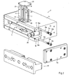
- the FIG. 1 shows a coupling device 1 for a handling device, which comprises a tensioning device 2 and a holder 40.
- the clamping device 2 is usually fixed to a handling device such as a robot or a robot arm, for example, while the holder 40 is arranged on a gripping tool or a tool or workpiece carrier pallet.
- the gripping tool or the pallet can be repeatedly fixed exactly on the clamping device 2.
- the holder 40 shown from the front is usually attached with its back to the pallet or the gripping tool.
- Both the clamping device 2 and the holder 40 have an elongated, preferably a substantially rectangular basic shape.
- An elongated basic shape of the tensioning device 2 has the advantage, in particular in comparison with round tensioning devices, that it is less bulky and therefore particularly suitable for flat pallets.
- the tensioning device 2 as well as the holder 40 are preferably at least twice as wide as high, in particular at least 2.5 times as wide as high.
- the tensioning device 2 comprises a base housing 3, which is provided on the front side with a slot-shaped recess 4.
- the recess 4 is bounded on the top and bottom by a respective strip 17, 18.
- a closure mechanism 5 is arranged, which comprises two laterally displaceable closure elements 6, 7 and a centrally disposed therebetween actuator, the latter is not apparent from this illustration.
- the closure mechanism 5 is arranged centrally, ie in the middle, on the tensioning device 2.
- the two closure elements 6, 7 are shown in the pushed-together basic position.
- two centering pins 24, 25 are arranged, which serve to position the holder 40 during clamping to the clamping device 2.
- slot-shaped recess 4 open connections 36, via which signals or Media from the jig 2 on the holder 40 and the associated pallet can be transmitted.
- 4 holes 37 are provided within the recess, which in particular in connection with narrow holders (not shown) are useful in that they can be used as centering for arranged on a narrow holder centering.
- the integrally formed holder 40 is seen in cross-section substantially T-shaped with an elongated, strip-shaped base 41 and two perpendicular projecting therefrom legs 42a, 42b.
- a closure opening 44 is inserted, which is provided with two lateral extensions 45, 46, which are tuned in shape and position on the closure elements 6, 7 of the tensioning device 2.
- the closure opening 44 is arranged centrally on the holder 40. So that the closure elements 6, 7 can be inserted into the closure opening 44 of the holder 40 in the pushed-together basic position, the width B of the closure opening 44 in the insertion region is greater than the external distance between the two closure elements 6, 7 in the collapsed state.
- the holder 40 is provided with five larger holes 49, 50, 58, 59, 60 and four smaller holes 57.
- the five larger holes 49, 50, 58, 59, 60 are used to receive screws (not shown), by means of which the holder 40 on a pallet (not shown) can be attached.
- the two outer bores 49, 50 serve at the same time as centering holes, by being matched to the centering pins 24, 25 of the clamping device 2.
- the four smaller holes 57 are used to carry electrical lines or media such as compressed air, etc., from the handling device to the pallet connected to the holder 40, and vice versa.
- the base 41 of the holder 40 is provided on the top and the bottom, each with a flat surface 51, 52, which surfaces 51, 52 parallel to each other.
- an increase 53, 54 is mounted in the form of a shoulder.
- the vertical distance between the two elevations 53, 54 is matched to the height of the slot-shaped recess 4 of the tensioning device 2 such that the holder 40 after tightening on the tensioning device 2 in the vertical direction with a small clearance of about 0.05 to 0, 3 Millimeters is received in the slot-shaped recess 4. Due to the shape and design of the holder 40, this is very robust and can be made comparatively inexpensive.
- the Fig. 2 shows the holder 40 from the back and the jig 2 in a partially exploded view.
- the two closure elements 6, 7 and the actuating member 8 of the clamping device 2 arranged therebetween can be seen.
- the two closure elements 6, 7 laterally, that is displaceable parallel to the end face of the clamping device 2.
- slot-shaped, in the strips 17, 18 embedded guides 19, 21 for the two closure elements 6, 7 can be seen.
- These slot-shaped guides 19, 21 extend through the upper 17 and lower bar 18 and are limited on the top or bottom by means of a respective plate, from this illustration, only the upper plate 20 can be seen.
- the two closure elements 6, 7 are provided in the upper and lower portions with flats 23, which serve as a guide and anti-rotation, when the closure elements 6, 7 are inserted into the slot-shaped guides 19, 21.
- Each closure element 6, 7 has in the upper and lower regions in each case two parallel, diametrically opposite flattenings, wherein only the front flats 23 can be seen in this illustration. A laterally attached to the base housing 3 cover plate 3a is also visible.
- plungers 10a, 10b can be seen, which are inserted into corresponding bores 16a, 16b which are embedded in the respective strip 17, 18.
- Each of these plungers 10a, 10b is associated with a compression spring 11a, 11b and a threaded pin 12a, 12b, the latter being screwed into a threaded bore recessed at the end of the bore 16a, 16b and serving to fix and bias the compression springs 11a, 11b.
- the second, in the present drawing right closure element 7 is biased inwardly in the direction of the actuator 8.
- the two closure elements 6, 7 are laterally displaceable along the slot-shaped guides 19, 21, wherein they can be pushed apart by a forward movement of the actuator 8 in the operative position, while they are in the retracted actuator 8 by means of the associated plunger back to the rest position are collapsible.
- Fig. 3 shows a cross section through the coupling device 1, namely the tensioning device 2 and the holder 40 in the untensioned state.
- the holder 40 is inserted into the slot-shaped recess 4 of the clamping device 2, wherein the shutter mechanism 5 assumes the initial state, so that the holder 40 is not tightened.
- the actuating member 8 In the initial state of the closure mechanism 5 shown here, the actuating member 8 is in the retracted basic position, while the two closure elements 6, 7 occupy the pushed-together basic position.
- the actuator 8 is wedge-shaped and has two tapered side surfaces.
- the closure mechanism 5 further comprises a clamping piston 27 which is displaceably arranged in a pressure chamber 29 and which is mechanically connected to the actuating member 8.
- the tensioning piston 27 is biased by means of several compression springs forward in the direction of the actuating member 8, wherein from this illustration, only one spring 28 can be seen.
- the clamping piston 27 is moved together with the actuator 8 to the rear in the illustrated starting position.
- the two centering pins 24, 25 of the clamping device 2 can be seen, which each extend in an associated centering hole 49, 50 of the holder 40.
- the holder 40 in the slit-shaped recess 4 of the clamping device 2 are inserted, especially when inserting the holder 40 in the slot-shaped recess 4 of the clamping device 2 at the same time the collapsed closure elements 6, 7 are inserted into the closure opening 44 of the holder 40.
- the Fig. 3a shows in an enlarged view parts of the shutter mechanism 5 of the clamping device together with the shutter opening 44 of the holder 40.
- the closure elements 6, 7 are shown slightly spaced from each other. From this representation, it can be seen that each closure element 6, 7 is provided on the inner side facing the actuating member 8 with a first flat surface 30, 31 pressure surface and on the outside with a second planar surface 32, 33 impact surface.
- the conically tapering side surfaces 34, 35 of the actuating member 8 are matched to the associated or facing pressure surfaces 30, 31 of the closure elements 6, 7.
- the two pressure surfaces 30, 31 on the inside of the respective closure element 6, 7 as well as the side surfaces 34, 35 of the actuator 8 extend at an angle of approximately 4 ° to 10 ° relative to the center axis M of the coupling device 1 and the tensioning device 2 and of the holder 40, wherein in the present example an angle of approximately 6 ° has been drawn.
- an angle of approximately 6 ° has been drawn.
- the lateral extensions 45, 46 of the closure opening 44 are each provided with an obliquely tapered clamping surface 47, 48, which are matched to the respective planar stop surface 32, 33 extending on the outside of the associated closure element 6, 7 that the respective closure element 6, 7 force and form fit comes to rest.
- the actuator 8 is displaceable along the center axis M.
- the Fig. 4 shows the coupling device 1 according to Fig. 3 in the tensed state while the Fig. 4a In an enlarged view parts of the shutter mechanism 5 of the clamping device together with the shutter opening 44 of the holder 40 shows.
- the pressure in the Pressure chamber 29 degraded, causing the clamping piston 27 moves under the action of the compression springs 28 in the illustrated front operative position.
- the actuator 8 pushes the actuator 8 also to the front, resulting in a lateral, outward displacement of the two closure elements 6, 7 by the tapered side surfaces 34, 35 of the actuator 8, the two closure elements 6, 7 apart.
- the Fig. 5 shows a further section through the clamping device 2. From this illustration, in particular the located between the two closure elements 6, 7 actuator 8 and the total of four plunger 10a, 10b, 13a, 13b can be seen, which by means of the associated compression springs 11 a, 11 b, 14a, 14b press the left 6 or right closure element 7 inwards in the direction of the actuating member 8.
- the plungers 10a, 10b, 13a, 13b are to ensure that the two Shutter elements 6, 7 move in their pushed-together basic position when the actuator 8 is retracted to its normal position.
- the two covers 20, 22 can be seen which delimit the guide slots 19, 21 serving for the lateral guidance of the closure elements 6, 7 upwards or downwards.
- the threaded pins 12a, 12b, 15a, 15b can be seen, by means of which the compression springs 11a, 11b, 14a, 14b are biased in the direction of the closure elements 6, 7.
- Fig. 6 shows a section through the front part of the clamping device 2 and the clamped thereto holder 40.
- the holder 40 is clamped stinfact backlash at the tensioning device 2.
- this is achieved in that the front side of the respective leg 42a, 42b forms a stop surface, with which the holder 40 comes into contact with the end face of the tensioning device 2 or the strips 17, 18 during clamping.
Abstract
Die Kupplungsvorrichtung (1) umfasst eine an einem Handhabungsgerät fixierbare Spannvorrichtung (2) und einen daran festspannbaren Halter (40). Sowohl die Spannvorrichtung (2) wie auch der Halter (40) besitzen eine im Wesentlichen rechteckige Grundform. Die Spannvorrichtung (2) weist einen Verschlussmechanismus (5) auf, der zwei lateral verschiebbare Verschlusselemente (6, 7) und ein dazwischen angeordnetes Betätigungsorgan umfasst. Der Halter (40) ist mit einer Verschlussöffnung (44) mit seitlichen Erweiterungen (45, 46) versehen. Zum Fixieren des Halters (40) an der Spannvorrichtung (2) werden die Verschlusselemente (6, 7) mittels des Betätigungsorgans in die seitlichen Erweiterungen (45, 46) der Verschlussöffnung (44) hineingepresst. Die Spannvorrichtung (2) ist zudem mit einer schlitzförmigen Aussparung (4) und der Halter (40) mit einer länglichen Basis (41) versehen, welch letztere in die schlitzförmige Aussparung (4) einführbar ist.The coupling device (1) comprises a clamping device (2) which can be fixed on a handling device and a holder (40) which can be clamped thereto. Both the clamping device (2) and the holder (40) have a substantially rectangular basic shape. The tensioning device (2) has a closure mechanism (5) which comprises two laterally displaceable closure elements (6, 7) and an actuating member arranged therebetween. The holder (40) is provided with a closure opening (44) with lateral extensions (45, 46). For fixing the holder (40) to the tensioning device (2), the closure elements (6, 7) are pressed into the lateral extensions (45, 46) of the closure opening (44) by means of the actuating member. The clamping device (2) is also provided with a slot-shaped recess (4) and the holder (40) with an elongated base (41), which latter in the slot-shaped recess (4) can be inserted.
Description
Die Erfindung betrifft eine Kupplungsvorrichtung für ein Handhabungsgerät. Derartige Kupplungsvorrichtungen umfassen eine Spannvorrichtung und einen daran fixierbaren Halter. Die Spannvorrichtung wird üblicherweise an einem Handhabungsgerät wie beispielsweise einem Roboter fixiert, während der Halter an einem Werkzeug- oder Werkstückträger -Palette- befestigt wird. Die Palette kann dann mittels des Halters wiederholt positionsgenau an der Spannvorrichtung festgespannt werden.The invention relates to a coupling device for a handling device. Such coupling devices comprise a tensioning device and a holder which can be fixed thereto. The jig is usually fixed to a handling device such as a robot while the holder is attached to a tool or workpiece carrier pallet. The pallet can then be repeatedly clamped by means of the holder accurately positioned on the jig.
Aus der
Die
Aus der
In der
Schliesslich geht aus der
Aufgabe der Erfindung ist es, eine dem eingangs genannten technischen Gebiet zugehörende Kupplungsvorrichtung für ein Handhabungsgerät zu schaffen, welche vergleichsweise flach jedoch trotzdem stabil ist und hohe Gewichte aufnehmen kann.The object of the invention is to provide a the technical field mentioned above associated coupling device for a handling device, which is relatively flat but still stable and can accommodate high weights.
Die Lösung der Aufgabe ist durch die Merkmale des Anspruchs 1 definiert. Gemäss der Erfindung besitzen die Spannvorrichtung wie auch der Halter eine längliche, insbesondere eine im Wesentlichen rechteckige Grundform, wobei der Halter eine Verschlussöffnung aufweist, die mit seitlichen Erweiterungen versehen ist und der Verschlussmechanismus zwei lateral verschiebbare Verschlusselemente und ein dazwischen angeordnetes Betätigungsorgan aufweist, mittels welchem die Verschlusselemente derart in die seitlichen Erweiterungen der Verschlussöffnung hineinpressbar sind, dass der Halter an der Spannvorrichtung festspannbar ist.The solution of the problem is defined by the features of
Eine derartige Kupplungsvorrichtung eignet sich insbesondere zum An- und Abkuppeln von Greifern und Paletten an ein Handhabungsgerät wie beispielsweise einen Roboter. Durch die längliche Gestaltung der Spannvorrichtung zusammen mit einem Halter, der eine Verschlussöffnung mit seitlichen Erweiterungen aufweist, an denen zwei lateral verschiebbare Verschlusselemente angreifen, wird die grundsätzliche Voraussetzung geschaffen, ein vergleichsweise flache Kupplungsvorrichtung zu schaffen, welche trotzdem hohe Gewichte aufnehmen kann.Such a coupling device is particularly suitable for coupling and uncoupling of grippers and pallets to a handling device such as a robot. Due to the elongated design of the clamping device together with a holder having a closure opening with lateral extensions, which engage two laterally displaceable closure elements, the fundamental requirement is created to provide a comparatively flat coupling device, which can still accommodate high weights.
Vorzugsweise ist der Verschlussmechanismus mittig an der Spannvorrichtung angeordnet, während die Verschlussöffnung mittig an dem Halter angeordnet ist. Eine solche Ausbildung ermöglicht einen einfachen und symmetrischen Aufbau der Spannvorrichtung.Preferably, the locking mechanism is arranged centrally on the tensioning device, while the closure opening is arranged centrally on the holder. Such a design allows a simple and symmetrical construction of the clamping device.
Besonders bevorzugt ist der Halter einstückig ausgebildet. Diese ermöglicht einerseits den Halter sehr stabil auszubilden und gleichzeitig kostengünstig zu fertigen.Particularly preferably, the holder is integrally formed. On the one hand, this makes it possible to design the holder in a very stable manner and at the same time to produce it cost-effectively.
Bei einer bevorzugten Weiterbildung der Kupplungsvorrichtung ist der Verschlussmechanismus zentral in einer schlitzförmigen Aussparung der Spannvorrichtung angeordnet und der Halter mit einer länglichen Basis versehen, in die die genannte Verschlussöffnung eingelassen ist, wobei die Basis des Halters in die genannte Aussparung der Spannvorrichtung einführbar ist. Eine schlitzförmige Aussparung der genannten Art bildet eine ideale Aufnahme für den Halter bzw. dessen Basis.In a preferred embodiment of the coupling device, the closure mechanism is arranged centrally in a slot-shaped recess of the tensioning device and the holder provided with an elongated base into which said closure opening is recessed, wherein the base of the holder is insertable into said recess of the tensioning device. A slot-shaped recess of the type mentioned forms an ideal receptacle for the holder or its base.
Besonders bevorzugt wird die schlitzförmige Aussparung der Spannvorrichtung nach oben und unten durch je eine Leiste begrenzt, wobei jede Leiste mit einem Führungsschlitz versehen ist, in welchem die Verschlusselemente lateral beweglich geführt sind. Die Führungsschlitze können vergleichsweise einfach in die jeweilige Leiste eingelassen werden.Particularly preferably, the slot-shaped recess of the clamping device is bounded above and below by a respective bar, each bar is provided with a guide slot in which the closure elements laterally movable are guided. The guide slots can be relatively easily embedded in the respective bar.
Bei einer weiteren bevorzugten Weiterbildung sind die Spannvorrichtung wie auch der Halter zumindest doppelt so breit wie hoch und an der Spannvorrichtung ist auf jeder Seite des Verschlussmechanismus ein Zentrierbolzen angeordnet, wobei der jeweilige Zentrierbolzen mit je einer an der Basis des Halters korrespondierend angeordneten Zentrieröffnung zusammenzuarbeiten bestimmt ist. Bei dieser Ausbildung können die Zentrierbolzen vergleichsweise weit auseinander angeordnet werden, was sowohl hinsichtlich der Stabilität wie auch der Positioniergenauigkeit Vorteile mit sich bringt.In a further preferred embodiment, the clamping device as well as the holder are at least twice as wide as high and the clamping device on each side of the shutter mechanism, a centering pin is arranged, wherein the respective centering pin is intended to cooperate with one corresponding to the base of the holder arranged centering , In this embodiment, the centering pins can be arranged comparatively far apart, which brings advantages in terms of both stability and positioning accuracy.
Bei einer weiteren bevorzugten Weiterbildung ist der Halter im Querschnitt gesehen im Wesentlichen T-förmig ausgebildet und weist zwei von der Basis rechtwinklig abstehende Schenkel auf. Ein derartiger Halter ist stabil und kann kostengünstig hergestellt werden.In a further preferred embodiment, the holder is seen in cross-section substantially T-shaped and has two legs projecting from the base at right angles. Such a holder is stable and can be produced inexpensively.
Bei einer weiteren bevorzugten Weiterbildung bildet die zur Basis gerichtete Rückseite des jeweiligen Schenkels eine Anschlagfläche, mit welcher der Halter beim Festspannen an der Stirnseite der Spannvorrichtung zur Anlage kommt. Mit dieser Ausbildung können die Schenkel des Halters als Anschläge genutzt werden, was im Hinblick auf eine kostengünstige Fertigung vorteilhaft ist.In a further preferred development, the rear side of the respective leg directed towards the base forms a stop surface with which the holder comes into contact with the end face of the tensioning device during clamping. With this design, the legs of the holder can be used as stops, which is advantageous in terms of cost-effective production.
Bei einer weiteren bevorzugten Weiterbildung ist der Halter im Übergangsbereich von der Basis zu dem jeweiligen Schenkel mit je einer Erhöhung versehen, wobei die Erhöhungen derart auf die schlitzförmige Aussparung der Spannvorrichtung abgestimmt sind, dass der Halter beim Festspannen an der Spannvorrichtung in vertikaler Richtung mit geringem Spiel in deren schlitzförmiger Aussparung aufgenommen ist. Diese Ausbildung ist im Hinblick auf hohe Lasten vorteilhaft, da ein Teil der vom Halter auf die Spannvorrichtung zu übertragenden Kräfte über diese Erhöhungen übertragen werden können.In a further preferred embodiment, the holder is provided in the transition region from the base to the respective leg, each with an increase, wherein the elevations are adapted to the slot-shaped recess of the clamping device, that the holder when tightening the clamping device in the vertical direction with little play is added in the slot-shaped recess. This design is advantageous in view of high loads, since part of the forces to be transmitted from the holder to the clamping device can be transmitted via these elevations.
Bei einer weiteren bevorzugten Weiterbildung ist das Betätigungsorgan zwischen einer zurückgezogenen Grundstellung und einer vorgeschobenen Wirkstellung verschiebbar, wobei es in der vorgeschobenen Wirkstellung die beiden Verschlusselemente derart in die seitlichen Erweiterungen der Verschlussöffnung hineinzudrücken bestimmt ist, dass die Verschlusselemente kraft- und/oder formschlüssig an die seitlichen Erweiterungen teilweise begrenzenden Spannflächen des Halters zur Anlage kommen. Ein solcher Verschlussmechanismus ist einfach und kostengünstig zu realisieren.In a further preferred development, the actuating member is displaceable between a retracted basic position and an advanced operative position, wherein in the advanced operative position the two closure elements are intended to be pressed into the lateral extensions of the closure opening in such a way that the closure elements are non-positively and / or positively connected to the lateral extensions partially limiting clamping surfaces of the holder come to rest. Such a closure mechanism is easy and inexpensive to implement.
Bei einer weiteren bevorzugten Weiterbildung ist das Betätigungsorgan keilförmig ausgebildet und besitzt zwei konisch zulaufende Seitenflächen, wobei das jeweilige Verschlusselement auf der dem Betätigungsorgan zugewandten Seite mit je einer planen Druckfläche versehen ist, die auf die zugeordnete Seitenfläche des Betätigungsorgans abgestimmt ist, wobei der Abstand und der Winkel zwischen den beiden Seitenflächen des Betätigungsorgans so gewählt ist, dass in der vorgeschobenen Wirkstellung des Betätigungsorgans ein Selbsthemmung zwischen dem Betätigungsorgan und den an den Spannflächen des Halters anliegenden Verschlusselementen erreicht wird. Eine derartige Ausbildung ist insbesondere im Hinblick auf eine hohe Betriebssicherheit von Vorteil, da der Verschlussmechanismus nach dem Vorschieben des Betätigungsorgans verriegelt ist und beispielsweise auch ein Stromausfall oder ein Leck in einer Versorgungsleitung keinen Einfluss auf die sichere Fixierung des Halters an der Spannvorrichtung hätte.In a further preferred embodiment, the actuating member is wedge-shaped and has two conically tapered side surfaces, wherein the respective closure element is provided on the actuating member side facing each with a flat pressure surface, which is matched to the associated side surface of the actuator, wherein the distance and the Angle between the two side surfaces of the actuator is chosen so that in the advanced operative position of the actuator, a self-locking between the actuator and the voltage applied to the clamping surfaces of the holder closure elements is achieved. Such a design is particularly advantageous in terms of high reliability, since the locking mechanism is locked after advancing the actuator and, for example, a power failure or a leak in a supply line would have no effect on the secure fixation of the holder to the jig.
Bei einer weiteren bevorzugten Weiterbildung ist das jeweilige Verschlusselement im Wesentlichen zylindrisch ausgebildet ist, wobei die jeweilige Mantelfläche mit einer planen Anschlagfläche versehen ist, welche auf die Spannflächen des Halters abgestimmt ist. Ein solches Verschlusselement ist einfach und kostengünstig zu fertigen und kann hohe Verriegelungskräfte übertragen.In a further preferred embodiment, the respective closure element is formed substantially cylindrical, wherein the respective lateral surface is provided with a planar stop surface, which is adapted to the clamping surfaces of the holder. Such a closure element is simple and inexpensive to manufacture and can transmit high locking forces.
Vorzugsweise ist jedem Verschlusselement der Spannvorrichtung zumindest ein federbelastetes Mittel zugeordnet, mittels welchem das jeweilige Verschlusselement in Richtung des Betätigungsorgans vorgespannt ist. Dadurch kann sichergestellt werden, dass sich das jeweilige Verschlusselement nach dem Zurückziehen des Betätigungsorgans in seine nach innen gerückte, zusammengeschobene Grundstellung verschiebt, so dass der Halter von der Spannvorrichtung entfernt werden kann.Preferably, each closure element of the clamping device is assigned at least one spring-loaded means, by means of which the respective closure element is biased in the direction of the actuating member. This can ensure that the respective closure element shifts after retraction of the actuator in its inwardly pushed, pushed together basic position, so that the holder can be removed from the jig.
Besonders bevorzugt umfasst der Verschlussmechanismus einen mittels Druckfedern belasteten Spannkolben, der mit dem Betätigungsorgan gekoppelt ist und dieses unter der Wirkung der Druckfedern die Wirkstellung zu drücken bestrebt ist. Dadurch wird eine zuverlässige Verriegelung des Halters an der Spannvorrichtung zusätzlich sichergestellt, da die Druckfedern das Betätigungsorgan in Richtung der vorgeschobene Wirkstellung belasten.Particularly preferably, the closure mechanism comprises a loaded by means of compression springs clamping piston which is coupled to the actuating member and this endeavors to press the active position under the action of the compression springs. As a result, a reliable locking of the holder is additionally ensured on the clamping device, since the compression springs load the actuator in the direction of the advanced operative position.
Bei einer weiteren bevorzugten Weiterbildung ist der Spannkolben entgegen der Kraft der Druckfedern pneumatisch, elektrisch oder hydraulisch in die Ausgangsstellung bewegbar ist. Dies sind bevorzugte Möglichkeiten, um den Spannkolben in die Ausgangsstellung zu bewegen und damit die Verriegelung aufzuheben.In a further preferred embodiment of the clamping piston is against the force of the springs pneumatically, electrically or hydraulically movable into the starting position. These are preferred ways to move the clamping piston in the starting position and thus cancel the lock.
Bei einer besonders bevorzugten Weiterbildung sind die die seitlichen Erweiterungen teilweise begrenzenden Spannflächen des Halters unter einem solchen Winkel zu der Bewegungsrichtung des Betätigungsorgans verlaufen, dass der Halter beim Festspannen an der Spannvorrichtung durch die sich an den Spannflächen des Halters anlegenden Verschlusselemente an die Spannvorrichtung herangezogen wird. Mit dieser Ausbildung wird der Halter beim Festspannen nicht nur fixiert sondern gleichzeitig an die Spannvorrichtung herangezogen.In a particularly preferred development, the lateral extensions of the clamping surfaces of the holder are partially at an angle to the direction of movement of the actuator, that the holder when tightening the tensioning device is used by the voltage applied to the clamping surfaces of the holder closure elements to the tensioning device. With this design, the holder is not only fixed during tightening but also used on the clamping device.
Bei einer weiteren bevorzugten Weiterbildung verlaufen die Spannflächen des Halters unter einem Winkel zwischen 30° und 60°, insbesondere zwischen 40° und 50° zu der Verschieberichtung des Betätigungsorgans. Auf diese Weise kann die axiale Bewegung des Betätigungsorgans besonders vorteilhaft zum Heranziehen des Halters beim Fixieren an der Spannvorrichtung genutzt werden.In a further preferred embodiment, the clamping surfaces of the holder extend at an angle between 30 ° and 60 °, in particular between 40 ° and 50 ° to the direction of displacement of the actuator. In this way, the axial movement of the actuator can be used particularly advantageous for pulling the holder when fixing to the tensioning device.
Nachfolgend wird die Erfindung anhand von Zeichnungen näher erläutert. Dabei zeigt:
- Fig. 1
- die aus einer Spannvorrichtung und einem Halter bestehende Kupplungsvorrichtung in einer perspektivischen Ansicht;
- Fig. 2
- den Halter und die Spannvorrichtung in teilweise explodierter Darstellung;
- Fig. 3
- einen Querschnitt durch die Spannvorrichtung und den Halter im ungespannten Zustand;
- Fig. 3a
- einen vergrösserten Ausschnitt aus der
Fig. 3 ; - Fig. 4
- einen Querschnitt durch die Spannvorrichtung und den daran festgespannten Halter;
- Fig. 4a
- einen vergrösserten Ausschnitt aus der
Fig. 4 ; - Fig. 5
- einen weiteren Schnitt durch die Spannvorrichtung;
- Fig. 6
- einen Schnitt durch den Vorderteil der Spannvorrichtung und den daran festgespannten Halter.
- Fig. 1
- the consisting of a clamping device and a holder coupling device in a perspective view;
- Fig. 2
- the holder and the clamping device in a partially exploded representation;
- Fig. 3
- a cross section through the tensioning device and the holder in the untensioned state;
- Fig. 3a
- an enlarged excerpt from the
Fig. 3 ; - Fig. 4
- a cross section through the tensioning device and the holder clamped thereto;
- Fig. 4a
- an enlarged excerpt from the
Fig. 4 ; - Fig. 5
- a further section through the clamping device;
- Fig. 6
- a section through the front part of the tensioning device and the holder clamped thereto.
Grundsätzlich sind in den Figuren gleiche Teile mit gleichen Bezugszeichen versehen.Basically, the same parts are provided with the same reference numerals in the figures.
Die
Die Spannvorrichtung 2 umfasst ein Grundgehäuse 3, das auf der Vorderseite mit einer schlitzförmigen Aussparung 4 versehen ist. Die Aussparung 4 wird auf der Ober- und Unterseite durch je eine Leiste 17, 18 begrenzt. Innerhalb dieser Aussparung 4 ist ein Verschlussmechanismus 5 angeordnet, der zwei lateral verschiebbare Verschlusselemente 6, 7 und ein zentral dazwischen angeordnetes Betätigungsorgan umfasst, wobei letzteres aus dieser Darstellung nicht ersichtlich ist. Der Verschlussmechanismus 5 ist dabei mittig, d.h. in der Mitte, an der Spannvorrichtung 2 angeordnet. Die beiden Verschlusselemente 6, 7 sind in der zusammengeschobenen Grundstellung dargestellt. Innerhalb der Aussparung 4 sind zudem zwei Zentrierbolzen 24, 25 angeordnet, welche der Positionierung des Halters 40 beim Festspannen an der Spannvorrichtung 2 dienen. In die schlitzförmige Aussparung 4 münden Anschlüsse 36, über welche Signale oder Medien von der Spannvorrichtung 2 auf den Halter 40 bzw. die damit verbundene Palette übertragen werden können. Zudem sind innerhalb der Aussparung 4 Bohrungen 37 vorgesehen, welche insbesondere im Zusammenhang mit schmalen Haltern (nicht dargestellt) von Nutzen sind, indem diese als Zentrierbohrungen für an einem schmalen Halter angeordnete Zentrierbolzen genutzt werden können.The
Der einstückig ausgebildete Halter 40 ist im Querschnitt gesehen im Wesentlichen T-förmig ausgebildet mit einer länglichen, leistenförmigen Basis 41 und zwei rechtwinklig davon abstehenden Schenkeln 42a, 42b. In die Basis 41 des Halters ist eine Verschlussöffnung 44 eingelassen, die mit zwei seitlichen Erweiterungen 45, 46 versehen ist, welche in Form und Lage auf die Verschlusselemente 6, 7 der Spannvorrichtung 2 abgestimmt sind. Die Verschlussöffnung 44 ist mittig an dem Halter 40 angeordnet. Damit die Verschlusselemente 6, 7 in der zusammengeschobenen Grundstellung in die Verschlussöffnung 44 des Halters 40 eingeführt werden können, ist die Breite B der Verschlussöffnung 44 im Einführbereich grösser als der äussere Abstand zwischen den beiden Verschlusselementen 6, 7 im zusammengeschobenen Zustand. Der Halter 40 ist mit fünf grösseren Bohrungen 49, 50, 58, 59, 60 und vier kleineren Bohrungen 57 versehen. Die fünf grösseren Bohrungen 49, 50, 58, 59, 60 dienen der Aufnahme von Schrauben (nicht dargestellt), mittels welchen der Halter 40 an einer Palette (nicht dargestellt) befestigt werden kann. Die beiden äusseren Bohrungen 49, 50 dienen dabei gleichzeitig auch als Zentrierbohrungen, indem sie auf die Zentrierbolzen 24, 25 der Spannvorrichtung 2 abgestimmt sind. Die vier kleineren Bohrungen 57 dienen der Durchführung von elektrischen Leitungen oder Medien wie beispielsweise Druckluft etc. von dem Handhabungsgerät auf die mit dem Halter 40 verbundene Palette und umgekehrt.The integrally formed
Die Basis 41 des Halters 40 ist auf der Oberseite und der Unterseite mit je einer planen Fläche 51, 52 versehen, welche Flächen 51, 52 parallel zueinander verlaufen. Im Übergang von der Fläche 51, 52 zu dem jeweiligen Schenkel 42a, 42b ist eine Erhöhung 53, 54 in Form eines Absatzes angebracht. Der vertikale Abstand zwischen den beiden Erhöhungen 53, 54 ist derart auf die Höhe der schlitzförmigen Aussparung 4 der Spannvorrichtung 2 abgestimmt, dass der Halter 40 nach dem Festspannen an der Spannvorrichtung 2 in vertikaler Richtung mit geringem Spiel von ca. 0,05 bis 0,3 Millimetern in der schlitzförmigen Aussparung 4 aufgenommen ist. Durch die Form und Gestaltung des Halters 40 ist dieser sehr robust und kann vergleichweise günstig hergestellt werden.The
Die
Des Weiteren sind zwei Stössel 10a, 10b erkennbar, welche in entsprechende, in die jeweilige Leiste 17, 18 eingelassenen Bohrungen 16a, 16b eingesetzt werden. Jedem dieser Stössel 10a, 10b ist eine Druckfeder 11a, 11b und ein Gewindestift 12a, 12b zugeordnet, welche letztere in eine am Ende der Bohrung 16a, 16b eingelassene Gewindebohrung eingeschraubt werden und der Fixierung und Vorspannung der Druckfedern 11a, 11b dienen. Mittels den beiden Stösseln 10a, 10b sowie den zugehörigen Druckfedern 11a, 11b und Gewindestiften 12a, 12b wird das zweite, in der vorliegenden Zeichnung rechte Verschlusselement 7 nach innen in Richtung des Betätigungsorgans 8 vorgespannt. Auf der anderen Seite der Spannvorrichtung 2 sind ebenfalls entsprechende Stössel, Federn und Gewindestifte angeordnet, welche das erste Verschlusselement 6 nach innen in Richtung des Betätigungsorgans 8 vorspannen, wobei die genannten, dem ersten Verschlusselement 6 zugeordneten Stössel, Federn und Gewindestifte aus dieser Darstellung nicht ersichtlich sind.Furthermore, two
Die beiden Verschlusselemente 6, 7 sind lateral entlang der schlitzförmigen Führungen 19, 21 verschiebbar, wobei sie durch eine nach vorne gerichtete Bewegung des Betätigungsorgans 8 auseinander in die Wirkstellung geschoben werden können, während sie bei zurückgezogenem Betätigungsorgan 8 mittels der zugeordneten Stössel wieder in die Ruhestellung zusammenschiebbar sind.The two
In dem hier dargestellten Zustand, in welchem das Betätigungsorgan 8 die zurückgezogene Grundstellung einnimmt und die beiden Verschlusselemente 6, 7 sich in dem zusammengeschobenen Ausgangszustand befinden, kann der Halter 40 in die schlitzförmige Aussparung 4 der Spannvorrichtung 2 eingeschoben werden, zumal beim Einschieben des Halter 40 in die schlitzförmige Aussparung 4 der Spannvorrichtung 2 gleichzeitig auch die zusammengeschobenen Verschlusselemente 6, 7 in die Verschlussöffnung 44 des Halters 40 eingeführt werden.In the state shown here, in which the
Die
Die
Die
Durch die erläuterte Ausgestaltung zusammen mit dem Verschlussmechanismus, welcher in der vorgängig beschriebenen Weise an der Verschlussöffnung des Halters 40 angreift, wird sichergestellt, dass der Halter 40 hohe Lasten und hohe Drehmomente aufnehmen kann. Diesbezügliche Versuche haben ergeben, dass eine Spannvorrichtung 2 mit einer Länge von ca. 210 Millimetern und einer Höhe von ca. 70 Millimetern einen Halter 40 wiederholbar genau und sicher fixieren kann, der mit einer Palette mit einer Länge von 800 Millimetern verbunden ist und eine Last von 500 Kilogramm trägt. Bei diesem Beispiel wird davon ausgegangen, dass die Last zentral auf der mit dem Halter verbundenen Palette angeordnet ist.By the explained embodiment together with the shutter mechanism, which engages in the manner previously described at the shutter opening of the
Es versteht sich, dass das vorgängig anhand der Zeichnungen erläuterte Ausführungsbeispiel keinesfalls als abschliessend zu betrachten ist, sondern dass im Rahmen des in den Patentansprüchen definierten Schutzumfangs durchaus von dem erläuterten Ausführungsbeispiel abweichende Gestaltungen möglich sind. So sind beispielsweise abweichende Gestaltungen der Verschlusselemente ebenso denkbar, wie ein doppelter Verschlussmechanismus, der mit zwei Betätigungselementen und je zwei zugeordneten Verschlusselementen wie auch zwei zugeordneten Verschlussöffnungen versehen ist. Auch eine Variation bezüglich der Anzahl und/oder Anordnung der Zentrierelemente ist ohne weiteres möglich.It is understood that the embodiment explained above with reference to the drawings is by no means to be considered as conclusive, but that within the scope of the scope defined in the claims quite different from the illustrated embodiment deviations are possible. For example, deviating designs of the closure elements are also conceivable, as is a double closure mechanism which is provided with two actuation elements and two associated closure elements as well as two associated closure openings. Also, a variation in the number and / or arrangement of the centering is readily possible.
Claims (18)
Applications Claiming Priority (1)
| Application Number | Priority Date | Filing Date | Title |
|---|---|---|---|
| CH00363/14A CH709351A1 (en) | 2014-03-11 | 2014-03-11 | Coupling device for a handling device. |
Publications (2)
| Publication Number | Publication Date |
|---|---|
| EP2918379A1 true EP2918379A1 (en) | 2015-09-16 |
| EP2918379B1 EP2918379B1 (en) | 2016-07-20 |
Family
ID=52464121
Family Applications (1)
| Application Number | Title | Priority Date | Filing Date |
|---|---|---|---|
| EP15000294.7A Active EP2918379B1 (en) | 2014-03-11 | 2015-02-02 | Coupling device for a handling device |
Country Status (15)
| Country | Link |
|---|---|
| US (1) | US9937595B2 (en) |
| EP (1) | EP2918379B1 (en) |
| JP (1) | JP6339953B2 (en) |
| KR (1) | KR102168530B1 (en) |
| CN (1) | CN104908050B (en) |
| AU (1) | AU2015200418A1 (en) |
| CA (1) | CA2880077C (en) |
| CH (1) | CH709351A1 (en) |
| DK (1) | DK2918379T3 (en) |
| ES (1) | ES2585379T3 (en) |
| HK (1) | HK1215007A1 (en) |
| PL (1) | PL2918379T3 (en) |
| RU (1) | RU2611621C2 (en) |
| SG (1) | SG10201500824TA (en) |
| TW (1) | TWI630994B (en) |
Cited By (1)
| Publication number | Priority date | Publication date | Assignee | Title |
|---|---|---|---|---|
| CN112171707A (en) * | 2020-10-10 | 2021-01-05 | 安徽工业大学 | Quick automatic interface device of end-of-arm actuating mechanism |
Families Citing this family (9)
| Publication number | Priority date | Publication date | Assignee | Title |
|---|---|---|---|---|
| DE102015218127A1 (en) * | 2015-09-22 | 2017-03-23 | Schunk Gmbh & Co. Kg Spann- Und Greiftechnik | Gripping or clamping device |
| JP6321852B1 (en) * | 2017-04-06 | 2018-05-09 | エスアールエンジニアリング株式会社 | Robot arm coupling device |
| DE102018106210A1 (en) * | 2018-03-16 | 2019-09-19 | Gressel Ag | Gripping and positioning device for transporting a clamping device between different positions |
| EP3578323B1 (en) * | 2018-06-05 | 2020-08-12 | C.R.F. Società Consortile per Azioni | A suction-type gripping device |
| CN109171966B (en) * | 2018-09-29 | 2021-05-07 | 上海微创医疗机器人(集团)股份有限公司 | Quick change device for surgical instrument |
| US11850733B2 (en) * | 2020-06-11 | 2023-12-26 | Ati Industrial Automation, Inc. | Robotic tool changer coupling mechanism with increased torsional rigidity and reduced freeplay |
| CN112549070A (en) * | 2020-12-10 | 2021-03-26 | 国网天津市电力公司 | Flexible automatic centering electric clamping jaw for charging robot |
| TWI790025B (en) * | 2021-12-06 | 2023-01-11 | 直得科技股份有限公司 | Mechanism and method for mechanically and automatically changing tool on end shaft of robot arm |
| TWI806612B (en) * | 2022-05-18 | 2023-06-21 | 直得科技股份有限公司 | Mechanicl automatic tool changing mechanism of end shaft of mechanical arm |
Citations (4)
| Publication number | Priority date | Publication date | Assignee | Title |
|---|---|---|---|---|
| JP3419543B2 (en) | 1994-04-22 | 2003-06-23 | エヌオーケー株式会社 | Parallel opening and closing chuck device |
| EP1707307A1 (en) | 2005-03-31 | 2006-10-04 | Schunk GmbH & Co. KG Fabrik für Spann- und Greifwerkzeuge | Quick clamp system |
| EP1970170A1 (en) | 2007-03-13 | 2008-09-17 | Star Seiki Co., Ltd. | Robot arm coupling device |
| DE102011008601A1 (en) * | 2010-01-14 | 2011-07-21 | ATI Industrial Automation, Inc., N.C. | Manually actuated robotic tool changer for use in automotive industry, has cam surface contacting rolling members in one of tool and master units and urging each member against surface of other unit to couple tool and master units together |
Family Cites Families (39)
| Publication number | Priority date | Publication date | Assignee | Title |
|---|---|---|---|---|
| JPS59175984A (en) * | 1983-03-22 | 1984-10-05 | フアナツク株式会社 | Hand exchanger for industrial robot |
| FR2578775B1 (en) * | 1985-03-13 | 1988-10-14 | Dassault Avions | DEVICE FOR COUPLING A TOOL HEAD TO THE MANIPULATOR ARM OF A ROBOT, AND SUPPORT FOR STORING SUCH HEAD TOOLS |
| DE3734052A1 (en) * | 1987-10-08 | 1989-04-20 | Hertel Ag Werkzeuge Hartstoff | QUICK-CHANGE CLAMPING DEVICE FOR MACHINE TOOLS |
| US4906123A (en) * | 1988-03-02 | 1990-03-06 | Wes-Tech, Inc. | Quick changecoupling system for robotic attachments |
| JP2635112B2 (en) * | 1988-07-20 | 1997-07-30 | 株式会社日立製作所 | Grip connection means |
| JP2505624B2 (en) * | 1990-06-28 | 1996-06-12 | ビー・エル・オートテック株式会社 | Master plate and tool plate for robot arm coupling device and robot arm coupling device combining them |
| JP3292927B2 (en) * | 1991-07-25 | 2002-06-17 | ヤマハ発動機株式会社 | Tool holding device |
| US5173017A (en) * | 1991-12-20 | 1992-12-22 | Kennametal Inc. | Apparatus to adapt a toolholder for mounting to a base member |
| JPH0661486U (en) | 1993-02-05 | 1994-08-30 | 三島光産株式会社 | Automatic tool changer |
| JPH07246584A (en) * | 1994-03-10 | 1995-09-26 | Nitta Ind Corp | Automatic tool change device |
| US5415066A (en) * | 1994-04-08 | 1995-05-16 | Kennametal Inc. | Apparatus for holding a toolholder shank |
| US5452631A (en) * | 1994-04-08 | 1995-09-26 | Kennametal Inc. | Apparatus for holding a toolholder shank utilizing a rotatable cam to minimize kickback |
| US6196094B1 (en) * | 1995-03-17 | 2001-03-06 | Kennametal Pc Inc. | Tool unit clamping apparatus having a locking mechanism with increased gripping force |
| US5927168A (en) * | 1995-04-17 | 1999-07-27 | Kennametal Inc. | Tool unit clamping apparatus having improved short stroke locking mechanism |
| DE29615613U1 (en) * | 1996-09-09 | 1997-08-28 | Stark Emil | Clamping device for clamping a quick-action clamping cylinder on a carrier plate for processing machines |
| TW379155B (en) * | 1997-10-31 | 2000-01-11 | Kosmek Kk | Transmission apparatus |
| US6000306A (en) * | 1998-06-12 | 1999-12-14 | Kennametal Inc. | Side activated tool unit clamping apparatus using mechanical advantage |
| DE19829955A1 (en) * | 1998-07-04 | 2000-01-05 | System 3R International Ab Vae | Connector for use in a coupling device |
| WO2000027596A1 (en) * | 1998-11-05 | 2000-05-18 | Pascal Kabushiki Kaisha | Tool connecting device for robot hand |
| FR2786848B1 (en) * | 1998-12-02 | 2001-02-09 | Legris Sa | BALL COUPLER |
| CN1371316A (en) * | 2000-07-06 | 2002-09-25 | 帕斯卡株式会社 | Tool Connecting device for robot hand |
| FR2817596B1 (en) * | 2000-12-06 | 2003-09-19 | Faurecia Sieges Automobile | ASSEMBLY SYSTEM USING A BALL ANCHORING DEVICE |
| JP2002361533A (en) * | 2001-06-07 | 2002-12-18 | Kosmek Ltd | Clamp device with datum function |
| WO2004060606A1 (en) * | 2002-12-27 | 2004-07-22 | Kosmek Ltd. | Positioning device |
| EP1449606B1 (en) * | 2003-02-18 | 2010-09-22 | Greenlee Textron Inc. | Universal quick change hole saw arbor |
| DE10317341B4 (en) * | 2003-04-15 | 2014-03-20 | Andreas Maier Gmbh & Co. Kg | Quick release cylinder with guide device |
| DE10317350A1 (en) * | 2003-04-15 | 2004-11-04 | Ssa System-Spann Ag | Quick release cylinder with simplified structure |
| US8585031B2 (en) * | 2003-04-15 | 2013-11-19 | Andreas Maier Gmbh & Co. Kg | Quick action clamping cylinder with a simplified structure |
| DE10317337B4 (en) * | 2003-04-15 | 2020-06-10 | Andreas Maier Gmbh & Co. Kg | Modular quick-release cylinders |
| DE10326239B4 (en) * | 2003-06-11 | 2007-05-16 | Ass Maschb Gmbh | Quick-change system |
| DK1529594T3 (en) * | 2003-11-06 | 2006-10-02 | Erowa Ag | Clamping device with at least three centering pins on one first coupling member and corresponding notes on another coupling member |
| DE102004006418A1 (en) * | 2004-02-09 | 2005-08-25 | Zero-Point-Systems Günther Stark GmbH | Quick release cylinder with safety device against blockage |
| US8005570B2 (en) * | 2006-03-14 | 2011-08-23 | Ati Industrial Automation | Robotic tool changer |
| JP4936329B2 (en) * | 2007-07-20 | 2012-05-23 | 株式会社スター精機 | Robot arm coupling device |
| US7762739B2 (en) * | 2007-08-31 | 2010-07-27 | Strategic Ideas, Llc | Fastener and assembly utilizing the same |
| JP5172551B2 (en) * | 2008-09-05 | 2013-03-27 | ビッグアルファ株式会社 | Joint unit |
| US8601918B2 (en) * | 2010-01-15 | 2013-12-10 | Kennametal Inc. | Toolholder assembly |
| US8844942B1 (en) * | 2010-06-25 | 2014-09-30 | Greatbatch Ltd. | Quick-load connector for a surgical tool |
| US8794418B1 (en) * | 2013-03-14 | 2014-08-05 | Ati Industrial Automation, Inc. | Ball lock compensator for use with a robotic tool |
-
2014
- 2014-03-11 CH CH00363/14A patent/CH709351A1/en not_active Application Discontinuation
-
2015
- 2015-01-27 CA CA2880077A patent/CA2880077C/en active Active
- 2015-01-29 AU AU2015200418A patent/AU2015200418A1/en not_active Abandoned
- 2015-01-29 TW TW104102973A patent/TWI630994B/en active
- 2015-02-02 EP EP15000294.7A patent/EP2918379B1/en active Active
- 2015-02-02 ES ES15000294.7T patent/ES2585379T3/en active Active
- 2015-02-02 DK DK15000294.7T patent/DK2918379T3/en active
- 2015-02-02 PL PL15000294T patent/PL2918379T3/en unknown
- 2015-02-03 SG SG10201500824TA patent/SG10201500824TA/en unknown
- 2015-02-16 US US14/623,229 patent/US9937595B2/en active Active
- 2015-03-06 KR KR1020150031552A patent/KR102168530B1/en active IP Right Grant
- 2015-03-10 JP JP2015047163A patent/JP6339953B2/en active Active
- 2015-03-10 RU RU2015108350A patent/RU2611621C2/en active
- 2015-03-11 CN CN201510106213.7A patent/CN104908050B/en active Active
-
2016
- 2016-03-14 HK HK16102872.1A patent/HK1215007A1/en unknown
Patent Citations (4)
| Publication number | Priority date | Publication date | Assignee | Title |
|---|---|---|---|---|
| JP3419543B2 (en) | 1994-04-22 | 2003-06-23 | エヌオーケー株式会社 | Parallel opening and closing chuck device |
| EP1707307A1 (en) | 2005-03-31 | 2006-10-04 | Schunk GmbH & Co. KG Fabrik für Spann- und Greifwerkzeuge | Quick clamp system |
| EP1970170A1 (en) | 2007-03-13 | 2008-09-17 | Star Seiki Co., Ltd. | Robot arm coupling device |
| DE102011008601A1 (en) * | 2010-01-14 | 2011-07-21 | ATI Industrial Automation, Inc., N.C. | Manually actuated robotic tool changer for use in automotive industry, has cam surface contacting rolling members in one of tool and master units and urging each member against surface of other unit to couple tool and master units together |
Cited By (1)
| Publication number | Priority date | Publication date | Assignee | Title |
|---|---|---|---|---|
| CN112171707A (en) * | 2020-10-10 | 2021-01-05 | 安徽工业大学 | Quick automatic interface device of end-of-arm actuating mechanism |
Also Published As
| Publication number | Publication date |
|---|---|
| TW201540446A (en) | 2015-11-01 |
| JP2015171756A (en) | 2015-10-01 |
| CN104908050B (en) | 2018-06-22 |
| DK2918379T3 (en) | 2016-11-14 |
| SG10201500824TA (en) | 2015-10-29 |
| AU2015200418A1 (en) | 2015-10-01 |
| US9937595B2 (en) | 2018-04-10 |
| JP6339953B2 (en) | 2018-06-06 |
| EP2918379B1 (en) | 2016-07-20 |
| HK1215007A1 (en) | 2016-08-12 |
| TWI630994B (en) | 2018-08-01 |
| CH709351A1 (en) | 2015-09-15 |
| RU2611621C2 (en) | 2017-02-28 |
| ES2585379T3 (en) | 2016-10-05 |
| KR102168530B1 (en) | 2020-10-22 |
| CA2880077A1 (en) | 2015-09-11 |
| PL2918379T3 (en) | 2017-01-31 |
| CN104908050A (en) | 2015-09-16 |
| KR20150106350A (en) | 2015-09-21 |
| RU2015108350A (en) | 2016-09-27 |
| US20150258647A1 (en) | 2015-09-17 |
| CA2880077C (en) | 2022-08-30 |
Similar Documents
| Publication | Publication Date | Title |
|---|---|---|
| EP2918379B1 (en) | Coupling device for a handling device | |
| DE102014119482B4 (en) | Tool clamping device, tool holder and tool carrier | |
| DE4314629C2 (en) | Device for the position-defined clamping of a workpiece at the workplace of a processing machine | |
| EP3263274B1 (en) | Clamping device and clamping system | |
| CH716410B1 (en) | Clamping device with a chuck and a releasably fixable workpiece carrier. | |
| DE102011080504B4 (en) | Clamping device and pallet handling system | |
| DE102005031142A1 (en) | Clamping device, base jaws and top jaws for this | |
| EP3983169B1 (en) | Clamping device and workpiece holding device with a clamping device | |
| EP0201456B1 (en) | Press with an upper and a lower plate for fixing a tool set | |
| EP0450383B1 (en) | Fastening and centring device | |
| EP3219437A1 (en) | Workpiece holder device and method for mounting a workpiece in a workpiece holding device | |
| EP2105226B2 (en) | Magnet chuck | |
| DE202008018093U1 (en) | Magnetic chuck | |
| DE102015113583B4 (en) | positioning | |
| EP2730368B1 (en) | Method for clamping a work piece carrier or a workpiece | |
| DE1503119A1 (en) | Machining device | |
| EP3623085A1 (en) | Collet chuck | |
| EP3569354B1 (en) | Device for fixing workpieces and processing unit | |
| DE19861091A1 (en) | Clamping device to fix workpiece or pallet to machine table, with clamping rail for precision fixing to machine table | |
| DE102016214434B3 (en) | Force-moment sensor for a robotic unit | |
| EP2103367A1 (en) | Clamping device for objects e.g. for workpieces to be processed | |
| EP1862241B1 (en) | Powered Chuck | |
| DE102016105357A1 (en) | Universal increase for separate clamping systems | |
| EP3366417B1 (en) | Pull bolt of a zero point clamping system | |
| EP3616831A1 (en) | Clamping device |
Legal Events
| Date | Code | Title | Description |
|---|---|---|---|
| PUAI | Public reference made under article 153(3) epc to a published international application that has entered the european phase |
Free format text: ORIGINAL CODE: 0009012 |
|
| AK | Designated contracting states |
Kind code of ref document: A1 Designated state(s): AL AT BE BG CH CY CZ DE DK EE ES FI FR GB GR HR HU IE IS IT LI LT LU LV MC MK MT NL NO PL PT RO RS SE SI SK SM TR |
|
| AX | Request for extension of the european patent |
Extension state: BA ME |
|
| 17P | Request for examination filed |
Effective date: 20151210 |
|
| RIC1 | Information provided on ipc code assigned before grant |
Ipc: B25J 15/04 20060101AFI20160114BHEP Ipc: B23Q 1/00 20060101ALI20160114BHEP |
|
| GRAP | Despatch of communication of intention to grant a patent |
Free format text: ORIGINAL CODE: EPIDOSNIGR1 |
|
| INTG | Intention to grant announced |
Effective date: 20160224 |
|
| GRAS | Grant fee paid |
Free format text: ORIGINAL CODE: EPIDOSNIGR3 |
|
| GRAA | (expected) grant |
Free format text: ORIGINAL CODE: 0009210 |
|
| AK | Designated contracting states |
Kind code of ref document: B1 Designated state(s): AL AT BE BG CH CY CZ DE DK EE ES FI FR GB GR HR HU IE IS IT LI LT LU LV MC MK MT NL NO PL PT RO RS SE SI SK SM TR |
|
| REG | Reference to a national code |
Ref country code: GB Ref legal event code: FG4D Free format text: NOT ENGLISH |
|
| REG | Reference to a national code |
Ref country code: CH Ref legal event code: EP Ref country code: CH Ref legal event code: NV Representative=s name: ROTTMANN, ZIMMERMANN + PARTNER AG, CH |
|
| REG | Reference to a national code |
Ref country code: IE Ref legal event code: FG4D Free format text: LANGUAGE OF EP DOCUMENT: GERMAN |
|
| REG | Reference to a national code |
Ref country code: AT Ref legal event code: REF Ref document number: 813657 Country of ref document: AT Kind code of ref document: T Effective date: 20160815 |
|
| REG | Reference to a national code |
Ref country code: DE Ref legal event code: R096 Ref document number: 502015000088 Country of ref document: DE |
|
| REG | Reference to a national code |
Ref country code: NL Ref legal event code: FP |
|
| REG | Reference to a national code |
Ref country code: ES Ref legal event code: FG2A Ref document number: 2585379 Country of ref document: ES Kind code of ref document: T3 Effective date: 20161005 |
|
| REG | Reference to a national code |
Ref country code: CH Ref legal event code: PCAR Free format text: NEW ADDRESS: GARTENSTRASSE 28 A, 5400 BADEN (CH) |
|
| REG | Reference to a national code |
Ref country code: SE Ref legal event code: TRGR |
|
| REG | Reference to a national code |
Ref country code: LT Ref legal event code: MG4D |
|
| REG | Reference to a national code |
Ref country code: DK Ref legal event code: T3 Effective date: 20161111 |
|
| PG25 | Lapsed in a contracting state [announced via postgrant information from national office to epo] |
Ref country code: RS Free format text: LAPSE BECAUSE OF FAILURE TO SUBMIT A TRANSLATION OF THE DESCRIPTION OR TO PAY THE FEE WITHIN THE PRESCRIBED TIME-LIMIT Effective date: 20160720 Ref country code: NO Free format text: LAPSE BECAUSE OF FAILURE TO SUBMIT A TRANSLATION OF THE DESCRIPTION OR TO PAY THE FEE WITHIN THE PRESCRIBED TIME-LIMIT Effective date: 20161020 Ref country code: IS Free format text: LAPSE BECAUSE OF FAILURE TO SUBMIT A TRANSLATION OF THE DESCRIPTION OR TO PAY THE FEE WITHIN THE PRESCRIBED TIME-LIMIT Effective date: 20161120 Ref country code: LT Free format text: LAPSE BECAUSE OF FAILURE TO SUBMIT A TRANSLATION OF THE DESCRIPTION OR TO PAY THE FEE WITHIN THE PRESCRIBED TIME-LIMIT Effective date: 20160720 Ref country code: HR Free format text: LAPSE BECAUSE OF FAILURE TO SUBMIT A TRANSLATION OF THE DESCRIPTION OR TO PAY THE FEE WITHIN THE PRESCRIBED TIME-LIMIT Effective date: 20160720 |
|
| REG | Reference to a national code |
Ref country code: SK Ref legal event code: T3 Ref document number: E 22200 Country of ref document: SK |
|
| REG | Reference to a national code |
Ref country code: FR Ref legal event code: PLFP Year of fee payment: 3 |
|
| PG25 | Lapsed in a contracting state [announced via postgrant information from national office to epo] |
Ref country code: PT Free format text: LAPSE BECAUSE OF FAILURE TO SUBMIT A TRANSLATION OF THE DESCRIPTION OR TO PAY THE FEE WITHIN THE PRESCRIBED TIME-LIMIT Effective date: 20161121 Ref country code: LV Free format text: LAPSE BECAUSE OF FAILURE TO SUBMIT A TRANSLATION OF THE DESCRIPTION OR TO PAY THE FEE WITHIN THE PRESCRIBED TIME-LIMIT Effective date: 20160720 Ref country code: GR Free format text: LAPSE BECAUSE OF FAILURE TO SUBMIT A TRANSLATION OF THE DESCRIPTION OR TO PAY THE FEE WITHIN THE PRESCRIBED TIME-LIMIT Effective date: 20161021 |
|
| REG | Reference to a national code |
Ref country code: DE Ref legal event code: R097 Ref document number: 502015000088 Country of ref document: DE |
|
| PG25 | Lapsed in a contracting state [announced via postgrant information from national office to epo] |
Ref country code: EE Free format text: LAPSE BECAUSE OF FAILURE TO SUBMIT A TRANSLATION OF THE DESCRIPTION OR TO PAY THE FEE WITHIN THE PRESCRIBED TIME-LIMIT Effective date: 20160720 Ref country code: RO Free format text: LAPSE BECAUSE OF FAILURE TO SUBMIT A TRANSLATION OF THE DESCRIPTION OR TO PAY THE FEE WITHIN THE PRESCRIBED TIME-LIMIT Effective date: 20160720 |
|
| PLBE | No opposition filed within time limit |
Free format text: ORIGINAL CODE: 0009261 |
|
| STAA | Information on the status of an ep patent application or granted ep patent |
Free format text: STATUS: NO OPPOSITION FILED WITHIN TIME LIMIT |
|
| PG25 | Lapsed in a contracting state [announced via postgrant information from national office to epo] |
Ref country code: BE Free format text: LAPSE BECAUSE OF NON-PAYMENT OF DUE FEES Effective date: 20170228 Ref country code: BG Free format text: LAPSE BECAUSE OF FAILURE TO SUBMIT A TRANSLATION OF THE DESCRIPTION OR TO PAY THE FEE WITHIN THE PRESCRIBED TIME-LIMIT Effective date: 20161020 Ref country code: SM Free format text: LAPSE BECAUSE OF FAILURE TO SUBMIT A TRANSLATION OF THE DESCRIPTION OR TO PAY THE FEE WITHIN THE PRESCRIBED TIME-LIMIT Effective date: 20160720 |
|
| 26N | No opposition filed |
Effective date: 20170421 |
|
| PG25 | Lapsed in a contracting state [announced via postgrant information from national office to epo] |
Ref country code: SI Free format text: LAPSE BECAUSE OF FAILURE TO SUBMIT A TRANSLATION OF THE DESCRIPTION OR TO PAY THE FEE WITHIN THE PRESCRIBED TIME-LIMIT Effective date: 20160720 |
|
| PG25 | Lapsed in a contracting state [announced via postgrant information from national office to epo] |
Ref country code: MC Free format text: LAPSE BECAUSE OF FAILURE TO SUBMIT A TRANSLATION OF THE DESCRIPTION OR TO PAY THE FEE WITHIN THE PRESCRIBED TIME-LIMIT Effective date: 20160720 |
|
| REG | Reference to a national code |
Ref country code: IE Ref legal event code: MM4A |
|
| PG25 | Lapsed in a contracting state [announced via postgrant information from national office to epo] |
Ref country code: LU Free format text: LAPSE BECAUSE OF NON-PAYMENT OF DUE FEES Effective date: 20170202 |
|
| REG | Reference to a national code |
Ref country code: BE Ref legal event code: MM Effective date: 20170228 |
|
| REG | Reference to a national code |
Ref country code: FR Ref legal event code: PLFP Year of fee payment: 4 |
|
| PG25 | Lapsed in a contracting state [announced via postgrant information from national office to epo] |
Ref country code: IE Free format text: LAPSE BECAUSE OF NON-PAYMENT OF DUE FEES Effective date: 20170202 |
|
| PG25 | Lapsed in a contracting state [announced via postgrant information from national office to epo] |
Ref country code: MT Free format text: LAPSE BECAUSE OF FAILURE TO SUBMIT A TRANSLATION OF THE DESCRIPTION OR TO PAY THE FEE WITHIN THE PRESCRIBED TIME-LIMIT Effective date: 20160720 |
|
| PG25 | Lapsed in a contracting state [announced via postgrant information from national office to epo] |
Ref country code: AL Free format text: LAPSE BECAUSE OF FAILURE TO SUBMIT A TRANSLATION OF THE DESCRIPTION OR TO PAY THE FEE WITHIN THE PRESCRIBED TIME-LIMIT Effective date: 20160720 |
|
| PG25 | Lapsed in a contracting state [announced via postgrant information from national office to epo] |
Ref country code: HU Free format text: LAPSE BECAUSE OF FAILURE TO SUBMIT A TRANSLATION OF THE DESCRIPTION OR TO PAY THE FEE WITHIN THE PRESCRIBED TIME-LIMIT; INVALID AB INITIO Effective date: 20150202 |
|
| PG25 | Lapsed in a contracting state [announced via postgrant information from national office to epo] |
Ref country code: CY Free format text: LAPSE BECAUSE OF FAILURE TO SUBMIT A TRANSLATION OF THE DESCRIPTION OR TO PAY THE FEE WITHIN THE PRESCRIBED TIME-LIMIT Effective date: 20160720 |
|
| PG25 | Lapsed in a contracting state [announced via postgrant information from national office to epo] |
Ref country code: MK Free format text: LAPSE BECAUSE OF FAILURE TO SUBMIT A TRANSLATION OF THE DESCRIPTION OR TO PAY THE FEE WITHIN THE PRESCRIBED TIME-LIMIT Effective date: 20160720 |
|
| PG25 | Lapsed in a contracting state [announced via postgrant information from national office to epo] |
Ref country code: TR Free format text: LAPSE BECAUSE OF FAILURE TO SUBMIT A TRANSLATION OF THE DESCRIPTION OR TO PAY THE FEE WITHIN THE PRESCRIBED TIME-LIMIT Effective date: 20160720 |
|
| PGFP | Annual fee paid to national office [announced via postgrant information from national office to epo] |
Ref country code: SK Payment date: 20210201 Year of fee payment: 7 |
|
| REG | Reference to a national code |
Ref country code: SK Ref legal event code: MM4A Ref document number: E 22200 Country of ref document: SK Effective date: 20220202 |
|
| PG25 | Lapsed in a contracting state [announced via postgrant information from national office to epo] |
Ref country code: SK Free format text: LAPSE BECAUSE OF NON-PAYMENT OF DUE FEES Effective date: 20220202 |
|
| PGFP | Annual fee paid to national office [announced via postgrant information from national office to epo] |
Ref country code: NL Payment date: 20230216 Year of fee payment: 9 |
|
| PGFP | Annual fee paid to national office [announced via postgrant information from national office to epo] |
Ref country code: FR Payment date: 20230221 Year of fee payment: 9 Ref country code: FI Payment date: 20230224 Year of fee payment: 9 Ref country code: DK Payment date: 20230220 Year of fee payment: 9 Ref country code: CZ Payment date: 20230123 Year of fee payment: 9 Ref country code: CH Payment date: 20230307 Year of fee payment: 9 Ref country code: AT Payment date: 20230217 Year of fee payment: 9 |
|
| PGFP | Annual fee paid to national office [announced via postgrant information from national office to epo] |
Ref country code: SE Payment date: 20230216 Year of fee payment: 9 Ref country code: PL Payment date: 20230123 Year of fee payment: 9 Ref country code: IT Payment date: 20230217 Year of fee payment: 9 Ref country code: GB Payment date: 20230221 Year of fee payment: 9 Ref country code: DE Payment date: 20230216 Year of fee payment: 9 |
|
| PGFP | Annual fee paid to national office [announced via postgrant information from national office to epo] |
Ref country code: ES Payment date: 20230426 Year of fee payment: 9 |