EP2918369A1 - Method for laser-beam gas cutting - Google Patents
Method for laser-beam gas cutting Download PDFInfo
- Publication number
- EP2918369A1 EP2918369A1 EP14000931.7A EP14000931A EP2918369A1 EP 2918369 A1 EP2918369 A1 EP 2918369A1 EP 14000931 A EP14000931 A EP 14000931A EP 2918369 A1 EP2918369 A1 EP 2918369A1
- Authority
- EP
- European Patent Office
- Prior art keywords
- laser
- assist gas
- cutting
- gas
- kerf
- Prior art date
- Legal status (The legal status is an assumption and is not a legal conclusion. Google has not performed a legal analysis and makes no representation as to the accuracy of the status listed.)
- Withdrawn
Links
- 238000005520 cutting process Methods 0.000 title claims abstract description 34
- 238000000034 method Methods 0.000 title claims abstract description 11
- 239000007789 gas Substances 0.000 claims description 64
- VNWKTOKETHGBQD-UHFFFAOYSA-N methane Chemical compound C VNWKTOKETHGBQD-UHFFFAOYSA-N 0.000 claims description 16
- 239000002737 fuel gas Substances 0.000 claims description 15
- 239000000203 mixture Substances 0.000 claims description 10
- 239000001257 hydrogen Substances 0.000 claims description 6
- 229910052739 hydrogen Inorganic materials 0.000 claims description 6
- 239000011261 inert gas Substances 0.000 claims description 5
- ATUOYWHBWRKTHZ-UHFFFAOYSA-N Propane Chemical compound CCC ATUOYWHBWRKTHZ-UHFFFAOYSA-N 0.000 claims description 4
- HSFWRNGVRCDJHI-UHFFFAOYSA-N alpha-acetylene Natural products C#C HSFWRNGVRCDJHI-UHFFFAOYSA-N 0.000 claims description 4
- QVGXLLKOCUKJST-UHFFFAOYSA-N atomic oxygen Chemical compound [O] QVGXLLKOCUKJST-UHFFFAOYSA-N 0.000 claims description 4
- 239000001273 butane Substances 0.000 claims description 4
- 125000002534 ethynyl group Chemical group [H]C#C* 0.000 claims description 4
- 239000000835 fiber Substances 0.000 claims description 4
- IJDNQMDRQITEOD-UHFFFAOYSA-N n-butane Chemical compound CCCC IJDNQMDRQITEOD-UHFFFAOYSA-N 0.000 claims description 4
- OFBQJSOFQDEBGM-UHFFFAOYSA-N n-pentane Natural products CCCCC OFBQJSOFQDEBGM-UHFFFAOYSA-N 0.000 claims description 4
- 239000003345 natural gas Substances 0.000 claims description 4
- 239000001301 oxygen Substances 0.000 claims description 4
- 229910052760 oxygen Inorganic materials 0.000 claims description 4
- 239000001294 propane Substances 0.000 claims description 2
- 125000004435 hydrogen atom Chemical class [H]* 0.000 claims 1
- 239000002184 metal Substances 0.000 description 10
- IJGRMHOSHXDMSA-UHFFFAOYSA-N Atomic nitrogen Chemical compound N#N IJGRMHOSHXDMSA-UHFFFAOYSA-N 0.000 description 8
- 238000003698 laser cutting Methods 0.000 description 6
- XKRFYHLGVUSROY-UHFFFAOYSA-N Argon Chemical compound [Ar] XKRFYHLGVUSROY-UHFFFAOYSA-N 0.000 description 4
- QQONPFPTGQHPMA-UHFFFAOYSA-N Propene Chemical compound CC=C QQONPFPTGQHPMA-UHFFFAOYSA-N 0.000 description 4
- 229910052757 nitrogen Inorganic materials 0.000 description 4
- 150000002431 hydrogen Chemical class 0.000 description 3
- 239000000463 material Substances 0.000 description 3
- MYMOFIZGZYHOMD-UHFFFAOYSA-N Dioxygen Chemical compound O=O MYMOFIZGZYHOMD-UHFFFAOYSA-N 0.000 description 2
- UFHFLCQGNIYNRP-UHFFFAOYSA-N Hydrogen Chemical compound [H][H] UFHFLCQGNIYNRP-UHFFFAOYSA-N 0.000 description 2
- 229910052786 argon Inorganic materials 0.000 description 2
- 238000002485 combustion reaction Methods 0.000 description 2
- 230000001419 dependent effect Effects 0.000 description 2
- CWYNVVGOOAEACU-UHFFFAOYSA-N Fe2+ Chemical compound [Fe+2] CWYNVVGOOAEACU-UHFFFAOYSA-N 0.000 description 1
- 229910000831 Steel Inorganic materials 0.000 description 1
- 239000012080 ambient air Substances 0.000 description 1
- 238000007664 blowing Methods 0.000 description 1
- 238000001816 cooling Methods 0.000 description 1
- 230000007423 decrease Effects 0.000 description 1
- 230000003247 decreasing effect Effects 0.000 description 1
- 238000010586 diagram Methods 0.000 description 1
- 230000003993 interaction Effects 0.000 description 1
- 238000003754 machining Methods 0.000 description 1
- 238000002844 melting Methods 0.000 description 1
- 230000008018 melting Effects 0.000 description 1
- 239000012768 molten material Substances 0.000 description 1
- 238000005457 optimization Methods 0.000 description 1
- 239000010959 steel Substances 0.000 description 1
Images
Classifications
-
- B—PERFORMING OPERATIONS; TRANSPORTING
- B23—MACHINE TOOLS; METAL-WORKING NOT OTHERWISE PROVIDED FOR
- B23K—SOLDERING OR UNSOLDERING; WELDING; CLADDING OR PLATING BY SOLDERING OR WELDING; CUTTING BY APPLYING HEAT LOCALLY, e.g. FLAME CUTTING; WORKING BY LASER BEAM
- B23K26/00—Working by laser beam, e.g. welding, cutting or boring
- B23K26/36—Removing material
- B23K26/38—Removing material by boring or cutting
-
- B—PERFORMING OPERATIONS; TRANSPORTING
- B23—MACHINE TOOLS; METAL-WORKING NOT OTHERWISE PROVIDED FOR
- B23K—SOLDERING OR UNSOLDERING; WELDING; CLADDING OR PLATING BY SOLDERING OR WELDING; CUTTING BY APPLYING HEAT LOCALLY, e.g. FLAME CUTTING; WORKING BY LASER BEAM
- B23K26/00—Working by laser beam, e.g. welding, cutting or boring
- B23K26/14—Working by laser beam, e.g. welding, cutting or boring using a fluid stream, e.g. a jet of gas, in conjunction with the laser beam; Nozzles therefor
-
- B—PERFORMING OPERATIONS; TRANSPORTING
- B23—MACHINE TOOLS; METAL-WORKING NOT OTHERWISE PROVIDED FOR
- B23K—SOLDERING OR UNSOLDERING; WELDING; CLADDING OR PLATING BY SOLDERING OR WELDING; CUTTING BY APPLYING HEAT LOCALLY, e.g. FLAME CUTTING; WORKING BY LASER BEAM
- B23K26/00—Working by laser beam, e.g. welding, cutting or boring
- B23K26/14—Working by laser beam, e.g. welding, cutting or boring using a fluid stream, e.g. a jet of gas, in conjunction with the laser beam; Nozzles therefor
- B23K26/1462—Nozzles; Features related to nozzles
- B23K26/1464—Supply to, or discharge from, nozzles of media, e.g. gas, powder, wire
- B23K26/1476—Features inside the nozzle for feeding the fluid stream through the nozzle
Definitions
- the invention concerns a method for laser-beam gas cutting of a workpiece with a focused laser-beam.
- Cutting characteristics of a cut provided by a laser-beam device are governed by various operational conditions, for example the power of the laser-beam used, the distance between the surface of the workpiece and the laser-beam nozzle and the composition of the assist gas.
- the quality of cutting deteriorates when cutting sheet metal layers of 3-4 mm or more.
- the cutting front of such lasers is relatively flat, which has a negative influence on the cutting quality.
- CO2 lasers thicker sheet metal workpieces can be cut, which provide acceptable cutting quality.
- CO2 lasers also have disadvantages compared to other cutting methods, for example plasma cutting.
- US 2010/0187209 A1 discloses a laser machining nozzle providing a main assist gas nozzle for emitting a laser-beam and a main assist gas, and an auxiliary assist gas nozzle surrounding the main assist gas nozzle for emitting an auxiliary assist gas.
- the teaching of this document is related to optimization of flow velocity of main assist gas and auxiliary assist gas with a view to cooling and shielding the cutting laser from the ambient atmosphere. The same gas is used as main assist gas and auxiliary assist gas.
- sheet metal thicknesses of substantially more than 3-4 mm can be cut with sufficient quality.
- CO2 lasers in accordance with the present invention hitherto achievable sufficient cutting qualities can be achieved for higher workpiece or sheet metal thicknesses.
- the second assist gas jet comprises or consists of a fuel gas, which is ingited in the kerf.
- fuel gases comprise at least one of the following: hydrogen, propene, butane, methane, acetylene, as well as mixtures of these, as for example natural gas.
- a fuel gas mixture i. e. a gas comprising a fuel gas together with other non-fuel gases
- one of said fuel gases can be mixed for example with oxygen.
- an inert gas such as argon or nitrogen can advantageously be added.
- the second assist gas jet comprises or consists of a gas or gas mixture which is combustible with ambient oxygen in the kerf.
- Advantageously usable fuel gases comprise at least one of the following: hydrogen, propene, butane, methane, acetylene, as well as mixtures of these, as for example natural gas.
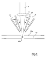
- Figure 1 is a schematically simplified section-diagram showing a laser cutting nozzle, through which a laser-beam is applied to a sheet metal work piece.
- a laser-beam for cutting a workpiece 10 is designated 2.
- Laser-beam 2 is focused onto the surface or slighty below the surface 10a of workpiece 10 by means of a focusing lense 4.
- kerf 10b By means of the laser-beam 2 interacting with the workpiece 10, a kerf 10b is created.
- kerf 10b can be provided e. g. as a groove, a slit or a notch, or, as in many practical applications, as a cut extending through the thickness of the workpiece.
- the kerf is typically dependent upon the properties of the workpiece being cut, the workpiece thickness, the focal length of lense 4, as well as the type of cutting gas used together with the laser 2, as will be explained in the following.
- the laser-beam 2 is guided towards the workpiece 10 through a first duct 12 of nozzle 6.
- a first assist gas jet 12a is also directed though first duct 12 onto workpiece 10.
- First duct 12 is arranged so that the first assist gas jet essentially surrounds the focused laser-beam 2, especially in the vicinity of surface 10a and kerf 10b of the workpiece 10.
- the material, of which the workpiece is made is heated to melting point.
- the first assist gas jet 12a provides a high-pressure gas to blow this molten material from the cutting area, whereby the kerf is cleared from monten material and the power requirement for laser-beam 2 is greatly decreased, as there is no need to raise the temperature of the (molten) material any further.
- the first assist gas jet 12a typically comprises an inert gas such as nitrogen. Usage of nitrogen as first assist gas jet provides an excellent cut quality, as the cutting region can be effectively shielded from ambient gases such as oxygene, so that for example oxides cannot attach to the cut edge, whereby a bright, oxide free edge for kerf 10b can be provided.
- the laser-beams will be moved relative to the workpiece 10, for example to cut a grove or a slit. If cutting of a notch is desired, there will be no relative movement between laser-beam 2 and workpiece 10 during cutting.
- the roughness of the kerf 10b provided by laser cutting increases with thickness of the workpiece, but decreases with laser power and cutting speed.
- a second duct 14 within nozzle 6, by means of which a second assist gas jet 14a is transported to the cutting area in the vicinity of kerf 10b.
- the second duct 14 is arranged such that the second assist gas jet 14a concentrically surrounds the first assist gas jet 12a.
- This second assist gas jet 14a comprises a gas or gas mixture which is combustible within kerf 10b.
- the second assist gas jet can comprise a fuel gas, such as hydrogen, propane, butane, methane, acetylene or a corresponding mixture, for example natural gas.
- a fuel gas such as hydrogen, propane, butane, methane, acetylene or a corresponding mixture, for example natural gas.
- Such fuel gases are ignited within the kerf 10b by means of the heat created therein by laser-beam 2. Additional ignition means are also conceivable.
- a second, non-combustible component can be added to the gas of the second assist gas jet 14a.
- additional gases can comprise oxygene.
- an inert gas such as argon or nitrogen can be added.
- the second assist gas jet with a gas or gas mixture which is combustible with ambient air.
- fuel gases are ignited within the kerf 10b by means of the heat created therein by laser-beam 2. Additional ignition means are also conceivable.
- melt-shear removal efficiency of the assist gas system can be significantly increased, which leads to an increased flow rate of the assist gas.
- the fuel gas will ignite as it reaches the hot section of kerf 10b, whereby it will produce additional heat, which will also expand the assist gas of the first assist gas jet, whereby flow velocity is increased.
- This increased flow velocity leads to a significant improvement of melt-shear removal, which in turn provides reduced roughness for the cutting area (kerf) and can also make possible increased cutting speeds.
- the second assist gas jet 14a is directed towards the kerf 10b in such a way that it is focused behind the first assist gas jet 12a, which it concentrically surrounds. This can be achieved by using a seperat nozzle behind the nozzle for the first gas jet.
Landscapes
- Engineering & Computer Science (AREA)
- Physics & Mathematics (AREA)
- Optics & Photonics (AREA)
- Plasma & Fusion (AREA)
- Mechanical Engineering (AREA)
- Laser Beam Processing (AREA)
Abstract
The invention relates to a method for laser-beam gas cutting of a workpiece by means of generating a kerf (10b) in the workpiece using a focused laser-beam (2), a first assist gas jet (12a) surrounding the laser-beam (2) being provided together with a second assist gas jet (14a) surrounding the first assist gas jet (12a), wherein the second assist gas jet (14a) is at least partly combusted in the kerf (10b) during cutting of the workpiece.
Description
- The invention concerns a method for laser-beam gas cutting of a workpiece with a focused laser-beam.
- Laser cutting of metal workpieces, for example made of steel, utilizing an assist gas for blowing molten metal through a kerf generated during cutting is known. Oxygen is most commonly used as assist gas when cutting ferrous metal workpeices. Inert gases can also be used, especially to produce oxide-free cut edges.
- Cutting characteristics of a cut provided by a laser-beam device are governed by various operational conditions, for example the power of the laser-beam used, the distance between the surface of the workpiece and the laser-beam nozzle and the composition of the assist gas.
- For laser cutting applications using diode, fibre or disc lasers, the quality of cutting deteriorates when cutting sheet metal layers of 3-4 mm or more. Here, it becomes noticeable that the cutting front of such lasers is relatively flat, which has a negative influence on the cutting quality.
- Using CO2 lasers, thicker sheet metal workpieces can be cut, which provide acceptable cutting quality. However, CO2 lasers also have disadvantages compared to other cutting methods, for example plasma cutting.
-
US 2010/0187209 A1 discloses a laser machining nozzle providing a main assist gas nozzle for emitting a laser-beam and a main assist gas, and an auxiliary assist gas nozzle surrounding the main assist gas nozzle for emitting an auxiliary assist gas. The teaching of this document is related to optimization of flow velocity of main assist gas and auxiliary assist gas with a view to cooling and shielding the cutting laser from the ambient atmosphere. The same gas is used as main assist gas and auxiliary assist gas. - It is an object of the present invention to enhance cutting quality in laser cutting applications, especially using diode lasers, fibre lasers, disc lasers or CO2 lasers.
- This object is achieved by providing a method including the features of claim 1.
- Advantageous embodiments of the invention are the subject matter of the dependent claims.
- By providing a first assist gas jet surrounding the cutting laser-beam and a second assist gas jet surrounding the first assist gas beam, the second assist gas jet being combusted in the kerf during cutting of the workpiece, a superior cutting quality for workpieces, especially for metal sheet workpieces, can be achieved.
- For example, when using a diode, fibre or disc laser in accordance with the present invention, sheet metal thicknesses of substantially more than 3-4 mm can be cut with sufficient quality. Correspondingly, when using CO2 lasers in accordance with the present invention, hitherto achievable sufficient cutting qualities can be achieved for higher workpiece or sheet metal thicknesses.
- Advantageously, the second assist gas jet comprises or consists of a fuel gas, which is ingited in the kerf. Advantageously usable fuel gases comprise at least one of the following: hydrogen, propene, butane, methane, acetylene, as well as mixtures of these, as for example natural gas.
- In case a fuel gas mixture, i. e. a gas comprising a fuel gas together with other non-fuel gases, shall be used, one of said fuel gases can be mixed for example with oxygen. In case of using hydrogen as fuel gas, an inert gas such as argon or nitrogen can advantageously be added.
- It is also advantageously possible that the second assist gas jet comprises or consists of a gas or gas mixture which is combustible with ambient oxygen in the kerf. Advantageously usable fuel gases comprise at least one of the following: hydrogen, propene, butane, methane, acetylene, as well as mixtures of these, as for example natural gas.
- Further advantageous embodiments of the invention will now be described with reference to the accompanying drawings.
-
Figure 1 is a schematically simplified section-diagram showing a laser cutting nozzle, through which a laser-beam is applied to a sheet metal work piece. - In
figure 1 , a laser-beam for cutting aworkpiece 10 is designated 2. Laser-beam 2 is focused onto the surface or slighty below thesurface 10a ofworkpiece 10 by means of a focusinglense 4. - By means of the laser-
beam 2 interacting with theworkpiece 10, akerf 10b is created. Depending on the type of laser cutting,kerf 10b can be provided e. g. as a groove, a slit or a notch, or, as in many practical applications, as a cut extending through the thickness of the workpiece. The kerf is typically dependent upon the properties of the workpiece being cut, the workpiece thickness, the focal length oflense 4, as well as the type of cutting gas used together with thelaser 2, as will be explained in the following. - The laser-
beam 2 is guided towards theworkpiece 10 through afirst duct 12 ofnozzle 6. A firstassist gas jet 12a is also directed thoughfirst duct 12 ontoworkpiece 10.First duct 12 is arranged so that the first assist gas jet essentially surrounds the focused laser-beam 2, especially in the vicinity ofsurface 10a andkerf 10b of theworkpiece 10. - By means of interaction of the laser-
beam 2 with theworkpiece 10 in the cutting area,i. e. kerf 10b, the material, of which the workpiece is made, is heated to melting point. The firstassist gas jet 12a provides a high-pressure gas to blow this molten material from the cutting area, whereby the kerf is cleared from monten material and the power requirement for laser-beam 2 is greatly decreased, as there is no need to raise the temperature of the (molten) material any further. - The first
assist gas jet 12a typically comprises an inert gas such as nitrogen. Usage of nitrogen as first assist gas jet provides an excellent cut quality, as the cutting region can be effectively shielded from ambient gases such as oxygene, so that for example oxides cannot attach to the cut edge, whereby a bright, oxide free edge forkerf 10b can be provided. - Depending on specific requirements, the laser-beams will be moved relative to the
workpiece 10, for example to cut a grove or a slit. If cutting of a notch is desired, there will be no relative movement between laser-beam 2 andworkpiece 10 during cutting. - The roughness of the
kerf 10b provided by laser cutting increases with thickness of the workpiece, but decreases with laser power and cutting speed. - In order to improve roughness qualities, i. e. especially in case of cutting
sheet metal workpieces 10 with increased thicknesses, especially over 3-4 mm, there is provided asecond duct 14 withinnozzle 6, by means of which a secondassist gas jet 14a is transported to the cutting area in the vicinity ofkerf 10b. Thesecond duct 14 is arranged such that the secondassist gas jet 14a concentrically surrounds the firstassist gas jet 12a. - This second
assist gas jet 14a comprises a gas or gas mixture which is combustible withinkerf 10b. Thus, the second assist gas jet can comprise a fuel gas, such as hydrogen, propane, butane, methane, acetylene or a corresponding mixture, for example natural gas. Such fuel gases are ignited within thekerf 10b by means of the heat created therein by laser-beam 2. Additional ignition means are also conceivable. - Depending on the extent of desired combustion within
kerf 10b, a second, non-combustible component can be added to the gas of the secondassist gas jet 14a. For example, such additional gases can comprise oxygene. In case hydrogen is used as fuel gas, an inert gas such as argon or nitrogen can be added. - It is also possible to provide the second assist gas jet with a gas or gas mixture which is combustible with ambient air. Such fuel gases are ignited within the
kerf 10b by means of the heat created therein by laser-beam 2. Additional ignition means are also conceivable. - By providing a combustion reaction for the gas of the second
assist gas jet 14a withinkerf 10b, a melt-shear removal efficiency of the assist gas system can be significantly increased, which leads to an increased flow rate of the assist gas. Especially, the fuel gas will ignite as it reaches the hot section ofkerf 10b, whereby it will produce additional heat, which will also expand the assist gas of the first assist gas jet, whereby flow velocity is increased. This increased flow velocity leads to a significant improvement of melt-shear removal, which in turn provides reduced roughness for the cutting area (kerf) and can also make possible increased cutting speeds. - Advantageously, the second
assist gas jet 14a is directed towards thekerf 10b in such a way that it is focused behind the firstassist gas jet 12a, which it concentrically surrounds. This can be achieved by using a seperat nozzle behind the nozzle for the first gas jet.
Claims (6)
- Method for laser-beam gas cutting of a workpiece by means of generating a kerf (10b) in the workpiece using a focused laser-beam (2), a first assist gas jet (12a) surrounding the laser-beam (2) being provided together with a second assist gas jet (14a) surrounding the first assist gas jet (12a),
characterized in that the second assist gas jet (14a) is at least partly combusted in the kerf (10b) during cutting of the workpiece. - Method according to claim 1, wherein the laser-beam (2) is provided by means of a diode laser, a fibre laser, a disc laser or a CO2 laser.
- Method according to claim 1 or claim 2, wherein the second assist gas jet (14a) comprises or consists of a fuel gas.
- Method according to claim 1 or claim 2, wherein the second assist gas jet (14a) comprises or consists of a gas or gas mixture which is combustible with ambient oxygen in the kerf (10b).
- Method according to any one of the preceding claims, wherein the first assist gas jet (12a) comprises or consists of an inert gas.
- Method according to any one of claims 3 to 5, wherein the fuel gas comprises at least one of the following gases: hydrogen, propane, butane, methane, acetylene or mixtures thereof such as natural gas.
Priority Applications (1)
| Application Number | Priority Date | Filing Date | Title |
|---|---|---|---|
| EP14000931.7A EP2918369A1 (en) | 2014-03-14 | 2014-03-14 | Method for laser-beam gas cutting |
Applications Claiming Priority (1)
| Application Number | Priority Date | Filing Date | Title |
|---|---|---|---|
| EP14000931.7A EP2918369A1 (en) | 2014-03-14 | 2014-03-14 | Method for laser-beam gas cutting |
Publications (1)
| Publication Number | Publication Date |
|---|---|
| EP2918369A1 true EP2918369A1 (en) | 2015-09-16 |
Family
ID=50287845
Family Applications (1)
| Application Number | Title | Priority Date | Filing Date |
|---|---|---|---|
| EP14000931.7A Withdrawn EP2918369A1 (en) | 2014-03-14 | 2014-03-14 | Method for laser-beam gas cutting |
Country Status (1)
| Country | Link |
|---|---|
| EP (1) | EP2918369A1 (en) |
Citations (2)
| Publication number | Priority date | Publication date | Assignee | Title |
|---|---|---|---|---|
| JP2001038481A (en) * | 1999-07-28 | 2001-02-13 | Koike Sanso Kogyo Co Ltd | Laser cutting method and laser cutting device |
| US20100187209A1 (en) | 2007-08-03 | 2010-07-29 | Mitsubishi Electric Corporation | Laser machining nozzle |
-
2014
- 2014-03-14 EP EP14000931.7A patent/EP2918369A1/en not_active Withdrawn
Patent Citations (2)
| Publication number | Priority date | Publication date | Assignee | Title |
|---|---|---|---|---|
| JP2001038481A (en) * | 1999-07-28 | 2001-02-13 | Koike Sanso Kogyo Co Ltd | Laser cutting method and laser cutting device |
| US20100187209A1 (en) | 2007-08-03 | 2010-07-29 | Mitsubishi Electric Corporation | Laser machining nozzle |
Similar Documents
| Publication | Publication Date | Title |
|---|---|---|
| EP2762263B1 (en) | Method and device for laser cutting process | |
| KR101436705B1 (en) | Laser/arc hybrid welding method and method of producing welded member using same | |
| Cao et al. | Research and progress in laser welding of wrought aluminum alloys. I. Laser welding processes | |
| US20120012570A1 (en) | Method for Cutting C-Mn Steel with a Fiber Laser | |
| US20120024831A1 (en) | Method for Cutting Stainless Steel with a Fiber Laser | |
| CN102958641A (en) | Laser-based lap welding of sheet metal components using laser induced protuberances to control gap | |
| Reisgen et al. | Welding of thick plate copper with laser beam welding under vacuum | |
| Börner et al. | Influence of ambient pressure on spattering and weld seam quality in laser beam welding with the solid-state laser | |
| JP2011218362A (en) | Laser and arc compound welding method and groove of metal plate for butt welding | |
| WO2024128929A1 (en) | System and method for processing or joining materials and their application | |
| US10201068B2 (en) | Method for the plasma cutting of workpieces | |
| WO2022046762A3 (en) | Methods of selection a direction of formation of slag puddle, of controlling cutting paths of a thermal processing torch, and of piercing a workpiece with a thermal processing torch | |
| CN102186625B (en) | Method for laser fusion cutting without cutting gas | |
| Petring et al. | Recent progress and innovative solutions for laser-arc hybrid welding | |
| JP6132296B2 (en) | Laser cutting method | |
| WO2023123735A1 (en) | Laser welding method for improving strength and toughness of weld joint | |
| JP2006095559A (en) | Laser irradiation arc welding method | |
| Singh et al. | Review on laser beam machining process parameter optimization | |
| JP2007283356A (en) | Method of manufacturing uoe steel pipe | |
| JP4875949B2 (en) | Gas cutting method | |
| EP4201576B1 (en) | Method for laser reactive cutting a thick metal workpiece; corresponding machine | |
| JP6529123B2 (en) | Thermal cutting machine | |
| JP2023133443A (en) | Laser beam machine | |
| Jang et al. | A study on the cutting efficiency of gas-laser hybrid cutting according to the optimal cutting speed when cutting 100 mm ultra-thick plates | |
| JP2016147291A (en) | Gas cutting crater |
Legal Events
| Date | Code | Title | Description |
|---|---|---|---|
| PUAI | Public reference made under article 153(3) epc to a published international application that has entered the european phase |
Free format text: ORIGINAL CODE: 0009012 |
|
| AK | Designated contracting states |
Kind code of ref document: A1 Designated state(s): AL AT BE BG CH CY CZ DE DK EE ES FI FR GB GR HR HU IE IS IT LI LT LU LV MC MK MT NL NO PL PT RO RS SE SI SK SM TR |
|
| AX | Request for extension of the european patent |
Extension state: BA ME |
|
| STAA | Information on the status of an ep patent application or granted ep patent |
Free format text: STATUS: THE APPLICATION IS DEEMED TO BE WITHDRAWN |
|
| 18D | Application deemed to be withdrawn |
Effective date: 20160317 |