EP2918333A1 - High pressure reactor for the synthesis of melamine - Google Patents
High pressure reactor for the synthesis of melamine Download PDFInfo
- Publication number
- EP2918333A1 EP2918333A1 EP14159283.2A EP14159283A EP2918333A1 EP 2918333 A1 EP2918333 A1 EP 2918333A1 EP 14159283 A EP14159283 A EP 14159283A EP 2918333 A1 EP2918333 A1 EP 2918333A1
- Authority
- EP
- European Patent Office
- Prior art keywords
- reactor
- urea
- heating elements
- melamine
- central duct
- Prior art date
- Legal status (The legal status is an assumption and is not a legal conclusion. Google has not performed a legal analysis and makes no representation as to the accuracy of the status listed.)
- Withdrawn
Links
- 229920000877 Melamine resin Polymers 0.000 title claims abstract description 35
- JDSHMPZPIAZGSV-UHFFFAOYSA-N melamine Chemical compound NC1=NC(N)=NC(N)=N1 JDSHMPZPIAZGSV-UHFFFAOYSA-N 0.000 title claims abstract description 35
- 230000015572 biosynthetic process Effects 0.000 title claims abstract description 12
- 238000003786 synthesis reaction Methods 0.000 title claims abstract description 11
- XSQUKJJJFZCRTK-UHFFFAOYSA-N Urea Chemical compound NC(N)=O XSQUKJJJFZCRTK-UHFFFAOYSA-N 0.000 claims abstract description 41
- 239000004202 carbamide Substances 0.000 claims abstract description 41
- 238000010438 heat treatment Methods 0.000 claims abstract description 39
- 238000000034 method Methods 0.000 claims abstract description 16
- 230000003197 catalytic effect Effects 0.000 claims abstract description 6
- 238000006243 chemical reaction Methods 0.000 claims description 18
- 239000007788 liquid Substances 0.000 claims description 14
- 230000002093 peripheral effect Effects 0.000 claims description 9
- 230000001174 ascending effect Effects 0.000 claims description 5
- 230000003134 recirculating effect Effects 0.000 claims description 3
- QGZKDVFQNNGYKY-UHFFFAOYSA-N Ammonia Chemical compound N QGZKDVFQNNGYKY-UHFFFAOYSA-N 0.000 description 11
- 239000007789 gas Substances 0.000 description 11
- CURLTUGMZLYLDI-UHFFFAOYSA-N Carbon dioxide Chemical compound O=C=O CURLTUGMZLYLDI-UHFFFAOYSA-N 0.000 description 9
- 229910021529 ammonia Inorganic materials 0.000 description 5
- 229910002092 carbon dioxide Inorganic materials 0.000 description 5
- 239000001569 carbon dioxide Substances 0.000 description 5
- 239000012530 fluid Substances 0.000 description 4
- 239000006227 byproduct Substances 0.000 description 2
- 230000000737 periodic effect Effects 0.000 description 2
- 238000005201 scrubbing Methods 0.000 description 2
- 238000005406 washing Methods 0.000 description 2
- 102000015933 Rim-like Human genes 0.000 description 1
- 108050004199 Rim-like Proteins 0.000 description 1
- 230000032683 aging Effects 0.000 description 1
- 230000008878 coupling Effects 0.000 description 1
- 238000010168 coupling process Methods 0.000 description 1
- 238000005859 coupling reaction Methods 0.000 description 1
- 239000007791 liquid phase Substances 0.000 description 1
- 238000012423 maintenance Methods 0.000 description 1
- 238000004519 manufacturing process Methods 0.000 description 1
- 229910000069 nitrogen hydride Inorganic materials 0.000 description 1
- 239000000047 product Substances 0.000 description 1
- 238000000746 purification Methods 0.000 description 1
- 230000000717 retained effect Effects 0.000 description 1
Images
Classifications
-
- C—CHEMISTRY; METALLURGY
- C07—ORGANIC CHEMISTRY
- C07D—HETEROCYCLIC COMPOUNDS
- C07D251/00—Heterocyclic compounds containing 1,3,5-triazine rings
- C07D251/02—Heterocyclic compounds containing 1,3,5-triazine rings not condensed with other rings
- C07D251/12—Heterocyclic compounds containing 1,3,5-triazine rings not condensed with other rings having three double bonds between ring members or between ring members and non-ring members
- C07D251/26—Heterocyclic compounds containing 1,3,5-triazine rings not condensed with other rings having three double bonds between ring members or between ring members and non-ring members with only hetero atoms directly attached to ring carbon atoms
- C07D251/40—Nitrogen atoms
- C07D251/54—Three nitrogen atoms
- C07D251/56—Preparation of melamine
- C07D251/60—Preparation of melamine from urea or from carbon dioxide and ammonia
-
- B—PERFORMING OPERATIONS; TRANSPORTING
- B01—PHYSICAL OR CHEMICAL PROCESSES OR APPARATUS IN GENERAL
- B01J—CHEMICAL OR PHYSICAL PROCESSES, e.g. CATALYSIS OR COLLOID CHEMISTRY; THEIR RELEVANT APPARATUS
- B01J10/00—Chemical processes in general for reacting liquid with gaseous media other than in the presence of solid particles, or apparatus specially adapted therefor
- B01J10/005—Chemical processes in general for reacting liquid with gaseous media other than in the presence of solid particles, or apparatus specially adapted therefor carried out at high temperatures in the presence of a molten material
-
- B—PERFORMING OPERATIONS; TRANSPORTING
- B01—PHYSICAL OR CHEMICAL PROCESSES OR APPARATUS IN GENERAL
- B01J—CHEMICAL OR PHYSICAL PROCESSES, e.g. CATALYSIS OR COLLOID CHEMISTRY; THEIR RELEVANT APPARATUS
- B01J19/00—Chemical, physical or physico-chemical processes in general; Their relevant apparatus
- B01J19/24—Stationary reactors without moving elements inside
- B01J19/2455—Stationary reactors without moving elements inside provoking a loop type movement of the reactants
- B01J19/246—Stationary reactors without moving elements inside provoking a loop type movement of the reactants internally, i.e. the mixture circulating inside the vessel such that the upward stream is separated physically from the downward stream(s)
-
- B—PERFORMING OPERATIONS; TRANSPORTING
- B01—PHYSICAL OR CHEMICAL PROCESSES OR APPARATUS IN GENERAL
- B01J—CHEMICAL OR PHYSICAL PROCESSES, e.g. CATALYSIS OR COLLOID CHEMISTRY; THEIR RELEVANT APPARATUS
- B01J3/00—Processes of utilising sub-atmospheric or super-atmospheric pressure to effect chemical or physical change of matter; Apparatus therefor
- B01J3/02—Feed or outlet devices therefor
-
- B—PERFORMING OPERATIONS; TRANSPORTING
- B01—PHYSICAL OR CHEMICAL PROCESSES OR APPARATUS IN GENERAL
- B01J—CHEMICAL OR PHYSICAL PROCESSES, e.g. CATALYSIS OR COLLOID CHEMISTRY; THEIR RELEVANT APPARATUS
- B01J3/00—Processes of utilising sub-atmospheric or super-atmospheric pressure to effect chemical or physical change of matter; Apparatus therefor
- B01J3/04—Pressure vessels, e.g. autoclaves
-
- B—PERFORMING OPERATIONS; TRANSPORTING
- B01—PHYSICAL OR CHEMICAL PROCESSES OR APPARATUS IN GENERAL
- B01J—CHEMICAL OR PHYSICAL PROCESSES, e.g. CATALYSIS OR COLLOID CHEMISTRY; THEIR RELEVANT APPARATUS
- B01J3/00—Processes of utilising sub-atmospheric or super-atmospheric pressure to effect chemical or physical change of matter; Apparatus therefor
- B01J3/04—Pressure vessels, e.g. autoclaves
- B01J3/042—Pressure vessels, e.g. autoclaves in the form of a tube
-
- B—PERFORMING OPERATIONS; TRANSPORTING
- B01—PHYSICAL OR CHEMICAL PROCESSES OR APPARATUS IN GENERAL
- B01J—CHEMICAL OR PHYSICAL PROCESSES, e.g. CATALYSIS OR COLLOID CHEMISTRY; THEIR RELEVANT APPARATUS
- B01J4/00—Feed or outlet devices; Feed or outlet control devices
- B01J4/001—Feed or outlet devices as such, e.g. feeding tubes
- B01J4/002—Nozzle-type elements
-
- C—CHEMISTRY; METALLURGY
- C07—ORGANIC CHEMISTRY
- C07D—HETEROCYCLIC COMPOUNDS
- C07D251/00—Heterocyclic compounds containing 1,3,5-triazine rings
- C07D251/02—Heterocyclic compounds containing 1,3,5-triazine rings not condensed with other rings
- C07D251/12—Heterocyclic compounds containing 1,3,5-triazine rings not condensed with other rings having three double bonds between ring members or between ring members and non-ring members
- C07D251/26—Heterocyclic compounds containing 1,3,5-triazine rings not condensed with other rings having three double bonds between ring members or between ring members and non-ring members with only hetero atoms directly attached to ring carbon atoms
- C07D251/40—Nitrogen atoms
- C07D251/54—Three nitrogen atoms
- C07D251/62—Purification of melamine
-
- B—PERFORMING OPERATIONS; TRANSPORTING
- B01—PHYSICAL OR CHEMICAL PROCESSES OR APPARATUS IN GENERAL
- B01J—CHEMICAL OR PHYSICAL PROCESSES, e.g. CATALYSIS OR COLLOID CHEMISTRY; THEIR RELEVANT APPARATUS
- B01J2219/00—Chemical, physical or physico-chemical processes in general; Their relevant apparatus
- B01J2219/00049—Controlling or regulating processes
- B01J2219/00051—Controlling the temperature
- B01J2219/00074—Controlling the temperature by indirect heating or cooling employing heat exchange fluids
- B01J2219/00076—Controlling the temperature by indirect heating or cooling employing heat exchange fluids with heat exchange elements inside the reactor
- B01J2219/00078—Fingers
-
- B—PERFORMING OPERATIONS; TRANSPORTING
- B01—PHYSICAL OR CHEMICAL PROCESSES OR APPARATUS IN GENERAL
- B01J—CHEMICAL OR PHYSICAL PROCESSES, e.g. CATALYSIS OR COLLOID CHEMISTRY; THEIR RELEVANT APPARATUS
- B01J2219/00—Chemical, physical or physico-chemical processes in general; Their relevant apparatus
- B01J2219/00049—Controlling or regulating processes
- B01J2219/00051—Controlling the temperature
- B01J2219/00074—Controlling the temperature by indirect heating or cooling employing heat exchange fluids
- B01J2219/00076—Controlling the temperature by indirect heating or cooling employing heat exchange fluids with heat exchange elements inside the reactor
- B01J2219/00081—Tubes
Definitions
- the invention relates to a high-pressure reactor for the synthesis of melamine.
- One of the known high-pressure synthesis processes comprises essentially three steps: an endothermic reaction which converts urea into melamine inside a first reactor, called primary reactor; a second step for removal of the carbon dioxide (CO2) by introducing gaseous ammonia and for reduction of the content of by-products, which are converted into melamine with increase in the conversion, inside a second reactor called secondary reactor or stripping reactor; a third step during which the gases separated in the top part of the primary and secondary reactors (called "off-gases”) are conveyed away for washing or scrubbing with urea before being conveyed to the urea plant.
- a lay-out of a plant which operates using this process is typically the following.
- the plant comprises a primary reactor, a secondary reactor and a scrubber, which are formed as separate cylindrical bodies.
- the urea melt is supplied to the primary reactor where the first reaction stage takes place that is the endothermic conversion into melamine; the effluent of said reactor is directed to the second reactor, where it undergoes a process of stripping of the gases contained therein, by means of gaseous ammonia.
- the liquid melamine is kept inside this secondary reactor for a certain dwell time (aging of the melamine) in order to convert the by-products formed inside the primary reactor into melamine.
- the liquid effluent from the secondary reactor (melamine melt) may be sent to a subsequent further purification step.
- the gases released inside the primary reactor and inside the secondary reactor form a stream of so-called off-gases, mainly containing ammonia and CO2 with small amounts of melamine; said stream of off-gases undergoes washing with urea melt inside the scrubber.
- the urea melt is thus heated before being supplied to the primary reactor; the off-gases at the scrubber outlet, which are melamine-free, are conveyed away and for example recycled for urea synthesis.
- the pressure is generally between 70 and 250 bar (7-25 MPa) and typically about 100-120 bar (10-12 MPa).
- US 6,815,545 describes a primary reactor according to the prior art, which essentially comprises: a vertical cylindrical body; a central duct; a bundle of heating tubes arranged in a ring around said central duct. The urea supply is introduced at the bottom of the central duct. According to the prior art, this reactor works substantially with a circulating flow which ascends inside the central duct and descends in the annular region occupied by the heating tubes.
- Said primary reactor design is widely used in the prior art, but has a number of drawbacks.
- the tube bundle has an outer diameter which is almost equivalent to the diameter of the reactor body, i.e. the entire apparatus. This means that, since it is required to be able to remove the tube bundle for periodic maintenance, a fully open flange with a tubesheet which has substantially the same diameter of the reactor - and is therefore thick, heavy and costly - is required. It should be noted that the reactor operates at high pressure (typically above 100 bar) and consequently the large-size flanges and the openings have a very high cost and may create problems as regards tightness.
- heating tube bundle is difficult to construct and hence costly; in particular, the heating tubes are bayonet (double-wall) tubes and require a double circular-rim tube plate, one of which has a large thickness.
- a third drawback is that the urea inlet in the centre of the heating bundle must be disconnected/connected in every operation. Said inlet, however, is difficult to access and increases the downtime and the risk of leakages from the seals owing to the difficult accessibility of the respective flanged joint.
- the invention aims to overcome the drawbacks and problems mentioned above.
- the reactor comprises a vertical body, at least one inlet for the urea melt, a set of heating elements, and a central duct, and is characterized in that said set of heating elements is arranged inside said central duct.
- Said central duct is advantageously delimited by a shell, preferably cylindrical, which surrounds the set of heating elements.
- This shell may be defined as being a low-pressure shell situated inside the reactor.
- the outer shell of the reactor may be defined as being a high-pressure shell, since it withstands the high pressure of the process.
- the central duct delimits an inner reaction zone and a peripheral reaction zone which communicate with each other and inside which a circulation flow is formed.
- the peripheral zone has the form of a circular rim and may be externally delimited by the shell of the reactor itself (high-pressure shell) or possibly by another inner shell.
- said peripheral zone around the central duct does not have any heating elements.
- the heating elements are arranged in the centre of the reactor, i.e. in the inner zone, rather than in the peripheral zone around the duct.
- the set of heating elements is a bundle of tubes which are connected to a tube plate at the bottom of the reactor and supplied with a suitable thermal fluid.
- the reactor comprises a distributor for the urea supply, which is connected to said urea melt inlet and is configured to introduce urea into said zone. More advantageously, said distributor is configured to introduce urea in a substantially uniform manner and with axially symmetry into said peripheral zone.
- said distributor is a toroidal body with a plurality of holes for introducing urea, which are distributed along its circumference; the distributor holes are directed so as to favour mixing of the urea melt with the fluid exiting the heating bundle, at the base of the central duct.
- said central duct extends at a predefined distance from a base of the set of heating elements, thus defining a passage for the recirculation of liquid. Even more advantageously, said central duct extends, inside the reactor, up to a height lower than the height of the heating elements.
- the mixing of the two fluids is ensured by the axial symmetry inside the annular cavity.
- a deflector in the form of a circular rim is preferably installed at the top end of the peripheral reaction zone. Said deflector prevents turbulence on the free surface of the fluid inside the reactor and has the function of directing the flow into the inner zone containing the heating bundle.
- the header for the liquid melamine may be associated with said deflector.
- the invention also relates to a process for the high-pressure synthesis of melamine from urea, comprising a primary reaction stage in which a stream of urea is converted into melamine with an endothermic reaction, inside a vertical reactor, characterized in that:
- the invention has the following advantages.
- the set of heating elements is less complex, more compact, easier to manufacture and therefore less costly than the conventional reactors, owing to the positioning in the centre of the reactor.
- the heating elements are arranged in a substantially cylindrical zone in the centre of the reactor, instead of in an annular zone with the same outer diameter of the reactor itself.
- the tubesheet has a smaller diameter and a smaller thickness, and the reactor body has a lower cost too because the flange coupling with the tubesheet is partially open rather than fully open.
- the periodic operations of disassembly of the heating bundle are simplified since it is no longer required to remove and restore the connections of the urea melt supply line. Consequently the plant downtimes are reduced.
- a reactor according to the invention may also incorporate a second reaction chamber, also called secondary section for stripping the liquid melamine with ammonia, and/or a section for scrubbing the gases.
- a second reaction chamber also called secondary section for stripping the liquid melamine with ammonia, and/or a section for scrubbing the gases.
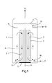
- Fig. 1 shows an example of a reactor which comprises a vertical body 1, an inlet 2 for the urea melt and a bundle of heating tubes 3 inside a central duct 7, delimited by a cylindrical shell 4.
- the tubes 3 are fixed to a tubesheet 5 which is located at the bottom of the reactor.
- the body 1 and the shell 4 are substantially axially symmetrical; preferably both the body 1 and the shell 4 are cylindrical.
- Said shell 4 may be defined as being a low-pressure inner shell. In fact, it remains immersed inside the liquid melamine, during the functioning of the reactor, and is not subject to a substantial difference in pressure.
- the shell 4 extends vertically inside the reactor up to a height which is advantageously lower than the height of the tubes 3, as shown.
- the shell also delimits a substantially annular shaped region 8 outside the duct 7.
- Said region 8 forms a peripheral reaction zone around the central duct 7.
- said region 8 is delimited between the shell 4 and the cylindrical body 1; in other embodiments, however, the outer wall of said region 8 may be delimited by another low-pressure shell inside the body 1.
- the bottom edge of the shell 4 is spaced from the tube plate 5, leaving a passage 9 for recirculation of the liquid.
- the urea supply line 2 is connected to a toroidal distributor 10 provided with a plurality of distribution holes along its circumference.
- the distributor 10 introduces urea in a uniform manner into the annular region 8.
- said urea distributor 10 is at the base of the duct 7, as shown in Fig. 1 , in the same region of said recirculation passage 9.
- the toroidal body of said distributor 10 may be positioned on the outer diameter of the reactor body 1 or outside the reactor itself, so as to be accessible externally.
- a diaphragm 6 is advantageously provided at the top of the annular region 8.
- the reactor Under normal operating conditions, the reactor is almost completely full of liquid, as indicated by the level 11.
- the flow line 13 indicates the crude melamine exiting via a suitable header 12.
- the flow line 14 indicates the gases mainly containing ammonia and CO2 (off-gases) which are extracted from the top of the reactor.
- Fig. 1 The arrows in Fig. 1 indicate the axially symmetrical recirculating flow which is formed inside the reactor.
- a descending flow is generated, said flow entering the base of the annular section 8 via the passage 9, and being mixed with the urea supply.
- an ascending flow is created, assisted by the formation of bubbles in the liquid phase.
- Part of the liquid mass which emerges from the top of the annular section 8, also as a result of the deflector 6, recirculates with a descending flow and enters again the duct 7 via the open top end of the shell 4.
- the flange 5 has relatively small dimensions, owing to the central arrangement of the tube bundle 3; the circulating flow inside the reactor descends inside the region directly in contact with the heating elements (i.e. inside the duct 7) and ascends inside the annular portion 8.
- the reactor has a substantially radial symmetry with respect to the axis A.
- the duct 7, the annular chamber 8 and the distributor 10 have a substantial radial symmetry with respect to said axis A. Therefore, the reactor may be defined as being axially symmetrical and the flow of the liquid is substantially axially symmetrical too.
- Fig. 1 shows an embodiment in which the melamine 13 is drawn off at a specific point via the header 12.
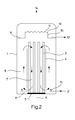
- the header for collecting the crude melamine is advantageously formed above the deflector 6, thus allowing the product to be uniformly collected along the whole circumference of the reactor.
- the reactor comprises a melamine header 15 having a top peripheral edge 16 positioned above said deflector 6.
- the melamine emerges through said header 15 and, once reached the edge 16, it flows out onto the deflector 6 which acts as an element for collecting the melamine.
- the collection of melamine takes place in a distributed and substantially axially symmetrical manner along a circumference formed, in the example, by the edge 16. The advantage of an improved symmetry of the flows is thus obtained.
Landscapes
- Chemical & Material Sciences (AREA)
- Organic Chemistry (AREA)
- Chemical Kinetics & Catalysis (AREA)
- Organic Low-Molecular-Weight Compounds And Preparation Thereof (AREA)
Abstract
Reactor for the synthesis of melamine from urea, in accordance with the highpressure non-catalytic process, comprising: a vertical reactor body (1), at least one inlet (2) for the urea melt, a set of heating elements (3), and a central duct (7), said set of heating elements (3) being arranged inside said central duct.
Description
- The invention relates to a high-pressure reactor for the synthesis of melamine.
- The processes for the synthesis of melamine from urea are commonly classified as low-pressure catalytic processes, typically below 1 MPa, and high-pressure non-catalytic catalytic processes, typically above 7 MPa. These processes are well-known in literature (see for example Ullmann's Encyclopedia of Industrial Chemistry, 6th ed., vol. 21, p. 205).
- One of the known high-pressure synthesis processes, as described for example in
US 6,815,545 , comprises essentially three steps: an endothermic reaction which converts urea into melamine inside a first reactor, called primary reactor; a second step for removal of the carbon dioxide (CO2) by introducing gaseous ammonia and for reduction of the content of by-products, which are converted into melamine with increase in the conversion, inside a second reactor called secondary reactor or stripping reactor; a third step during which the gases separated in the top part of the primary and secondary reactors (called "off-gases") are conveyed away for washing or scrubbing with urea before being conveyed to the urea plant. - A lay-out of a plant which operates using this process is typically the following.
- The plant comprises a primary reactor, a secondary reactor and a scrubber, which are formed as separate cylindrical bodies. The urea melt is supplied to the primary reactor where the first reaction stage takes place that is the endothermic conversion into melamine; the effluent of said reactor is directed to the second reactor, where it undergoes a process of stripping of the gases contained therein, by means of gaseous ammonia. In general, the liquid melamine is kept inside this secondary reactor for a certain dwell time (aging of the melamine) in order to convert the by-products formed inside the primary reactor into melamine. The liquid effluent from the secondary reactor (melamine melt) may be sent to a subsequent further purification step.
- The gases released inside the primary reactor and inside the secondary reactor form a stream of so-called off-gases, mainly containing ammonia and CO2 with small amounts of melamine; said stream of off-gases undergoes washing with urea melt inside the scrubber. The urea melt is thus heated before being supplied to the primary reactor; the off-gases at the scrubber outlet, which are melamine-free, are conveyed away and for example recycled for urea synthesis.
- The pressure is generally between 70 and 250 bar (7-25 MPa) and typically about 100-120 bar (10-12 MPa).
-
US 6,815,545 describes a primary reactor according to the prior art, which essentially comprises: a vertical cylindrical body; a central duct; a bundle of heating tubes arranged in a ring around said central duct. The urea supply is introduced at the bottom of the central duct. According to the prior art, this reactor works substantially with a circulating flow which ascends inside the central duct and descends in the annular region occupied by the heating tubes. - Said primary reactor design is widely used in the prior art, but has a number of drawbacks.
- The tube bundle has an outer diameter which is almost equivalent to the diameter of the reactor body, i.e. the entire apparatus. This means that, since it is required to be able to remove the tube bundle for periodic maintenance, a fully open flange with a tubesheet which has substantially the same diameter of the reactor - and is therefore thick, heavy and costly - is required. It should be noted that the reactor operates at high pressure (typically above 100 bar) and consequently the large-size flanges and the openings have a very high cost and may create problems as regards tightness.
- Another drawback consists in the fact that the heating tube bundle is difficult to construct and hence costly; in particular, the heating tubes are bayonet (double-wall) tubes and require a double circular-rim tube plate, one of which has a large thickness.
- A third drawback is that the urea inlet in the centre of the heating bundle must be disconnected/connected in every operation. Said inlet, however, is difficult to access and increases the downtime and the risk of leakages from the seals owing to the difficult accessibility of the respective flanged joint.
- The invention aims to overcome the drawbacks and problems mentioned above.
- This purpose is achieved with a reactor and a process for the synthesis of melamine from urea using the high-pressure non-catalytic process, according to the accompanying claims.
- The reactor comprises a vertical body, at least one inlet for the urea melt, a set of heating elements, and a central duct, and is characterized in that said set of heating elements is arranged inside said central duct.
- Said central duct is advantageously delimited by a shell, preferably cylindrical, which surrounds the set of heating elements. This shell may be defined as being a low-pressure shell situated inside the reactor. The outer shell of the reactor may be defined as being a high-pressure shell, since it withstands the high pressure of the process.
- The central duct delimits an inner reaction zone and a peripheral reaction zone which communicate with each other and inside which a circulation flow is formed. The peripheral zone has the form of a circular rim and may be externally delimited by the shell of the reactor itself (high-pressure shell) or possibly by another inner shell. Advantageously, according to the invention, said peripheral zone around the central duct does not have any heating elements.
- According to the invention, the heating elements are arranged in the centre of the reactor, i.e. in the inner zone, rather than in the peripheral zone around the duct. Preferably, the set of heating elements is a bundle of tubes which are connected to a tube plate at the bottom of the reactor and supplied with a suitable thermal fluid.
- In a preferred embodiment, the reactor comprises a distributor for the urea supply, which is connected to said urea melt inlet and is configured to introduce urea into said zone. More advantageously, said distributor is configured to introduce urea in a substantially uniform manner and with axially symmetry into said peripheral zone.
- In a preferred embodiment, said distributor is a toroidal body with a plurality of holes for introducing urea, which are distributed along its circumference; the distributor holes are directed so as to favour mixing of the urea melt with the fluid exiting the heating bundle, at the base of the central duct.
- In an even more preferred embodiment, said central duct extends at a predefined distance from a base of the set of heating elements, thus defining a passage for the recirculation of liquid. Even more advantageously, said central duct extends, inside the reactor, up to a height lower than the height of the heating elements.
- As a result of the configuration described it is possible to create a descending flow inside the central duct in the presence of the heating elements and an ascending recirculating flow in the surrounding annular zone (or rim), where there are no heating elements. Consequently, a descending flow is obtained in the heated reaction zone, as in the reactors of the prior art. This constitutes an advantage because the process conditions which are familiar to persons skilled in the art are retained, but with the constructional advantages arising from positioning the heating tubes in the central part of the reactor.
- The mixing of the two fluids is ensured by the axial symmetry inside the annular cavity.
- A deflector in the form of a circular rim is preferably installed at the top end of the peripheral reaction zone. Said deflector prevents turbulence on the free surface of the fluid inside the reactor and has the function of directing the flow into the inner zone containing the heating bundle. In certain preferred embodiments the header for the liquid melamine may be associated with said deflector.
- The invention also relates to a process for the high-pressure synthesis of melamine from urea, comprising a primary reaction stage in which a stream of urea is converted into melamine with an endothermic reaction, inside a vertical reactor, characterized in that:
- said primary reaction stage is performed with a flow circulating inside a liquid mass comprising melamine and urea, comprising a descending flow in a substantially column-like region in the centre of said reactor, directly heated by the presence of heating elements, and an ascending flow in a substantially rimlike region around said column, without heating elements, inside which the urea supply is introduced.
- The invention has the following advantages. The set of heating elements is less complex, more compact, easier to manufacture and therefore less costly than the conventional reactors, owing to the positioning in the centre of the reactor. In fact, the heating elements are arranged in a substantially cylindrical zone in the centre of the reactor, instead of in an annular zone with the same outer diameter of the reactor itself.
- With reference, for example, to heating elements in the form of tubes, the tubesheet has a smaller diameter and a smaller thickness, and the reactor body has a lower cost too because the flange coupling with the tubesheet is partially open rather than fully open. Owing to the proposed configuration, the periodic operations of disassembly of the heating bundle are simplified since it is no longer required to remove and restore the connections of the urea melt supply line. Consequently the plant downtimes are reduced. Finally it is possible to design and construct large-size reactors more easily owing to the greater simplicity and the smaller dimensions of the heating bundle.
- In some embodiments, a reactor according to the invention may also incorporate a second reaction chamber, also called secondary section for stripping the liquid melamine with ammonia, and/or a section for scrubbing the gases.
- The detailed description which follows relates to a preferred embodiment, described by way of a non-limiting example.
-
-
Fig. 1 is a schematic cross-section of a primary reactor for the high-pressure synthesis of melamine, according to a preferred embodiment of the invention. -
Fig. 2 shows a variant of the reactor shown inFig. 1 , according to another embodiment of the invention. -
Fig. 1 shows an example of a reactor which comprises avertical body 1, aninlet 2 for the urea melt and a bundle ofheating tubes 3 inside acentral duct 7, delimited by acylindrical shell 4. - The
tubes 3 are fixed to atubesheet 5 which is located at the bottom of the reactor. - The
body 1 and theshell 4 are substantially axially symmetrical; preferably both thebody 1 and theshell 4 are cylindrical. -
Said shell 4 may be defined as being a low-pressure inner shell. In fact, it remains immersed inside the liquid melamine, during the functioning of the reactor, and is not subject to a substantial difference in pressure. - The
shell 4 extends vertically inside the reactor up to a height which is advantageously lower than the height of thetubes 3, as shown. - The shell also delimits a substantially annular shaped
region 8 outside theduct 7.Said region 8 forms a peripheral reaction zone around thecentral duct 7. In the example according toFig. 1 saidregion 8 is delimited between theshell 4 and thecylindrical body 1; in other embodiments, however, the outer wall of saidregion 8 may be delimited by another low-pressure shell inside thebody 1. - The bottom edge of the
shell 4 is spaced from thetube plate 5, leaving apassage 9 for recirculation of the liquid. - The
urea supply line 2 is connected to atoroidal distributor 10 provided with a plurality of distribution holes along its circumference. Thus configured, thedistributor 10 introduces urea in a uniform manner into theannular region 8. - Advantageously said
urea distributor 10 is at the base of theduct 7, as shown inFig. 1 , in the same region of saidrecirculation passage 9. In some variants (not shown) the toroidal body of saiddistributor 10 may be positioned on the outer diameter of thereactor body 1 or outside the reactor itself, so as to be accessible externally. - A
diaphragm 6 is advantageously provided at the top of theannular region 8. - Under normal operating conditions, the reactor is almost completely full of liquid, as indicated by the
level 11. Theflow line 13 indicates the crude melamine exiting via asuitable header 12. Theflow line 14 indicates the gases mainly containing ammonia and CO2 (off-gases) which are extracted from the top of the reactor. - The arrows in
Fig. 1 indicate the axially symmetrical recirculating flow which is formed inside the reactor. Inside the central duct 7 a descending flow is generated, said flow entering the base of theannular section 8 via thepassage 9, and being mixed with the urea supply. Inside theannular section 8 an ascending flow is created, assisted by the formation of bubbles in the liquid phase. Part of the liquid mass which emerges from the top of theannular section 8, also as a result of thedeflector 6, recirculates with a descending flow and enters again theduct 7 via the open top end of theshell 4. - The conversion of urea into melamine takes place in the
zones - From
Fig. 1 it is possible to better appreciate a number of advantages of the invention and in particular: theflange 5 has relatively small dimensions, owing to the central arrangement of thetube bundle 3; the circulating flow inside the reactor descends inside the region directly in contact with the heating elements (i.e. inside the duct 7) and ascends inside theannular portion 8. - The reactor has a substantially radial symmetry with respect to the axis A. In particular, the
duct 7, theannular chamber 8 and thedistributor 10 have a substantial radial symmetry with respect to said axis A. Therefore, the reactor may be defined as being axially symmetrical and the flow of the liquid is substantially axially symmetrical too. -
Fig. 1 shows an embodiment in which themelamine 13 is drawn off at a specific point via theheader 12. - In the variant according to
Fig. 2 , the header for collecting the crude melamine is advantageously formed above thedeflector 6, thus allowing the product to be uniformly collected along the whole circumference of the reactor. More particularly, in this embodiment the reactor comprises amelamine header 15 having a topperipheral edge 16 positioned above saiddeflector 6. The melamine emerges through saidheader 15 and, once reached theedge 16, it flows out onto thedeflector 6 which acts as an element for collecting the melamine. In this embodiment, the collection of melamine takes place in a distributed and substantially axially symmetrical manner along a circumference formed, in the example, by theedge 16. The advantage of an improved symmetry of the flows is thus obtained.
Claims (14)
- Reactor for the synthesis of melamine from urea, according to the high-pressure non-catalytic process, comprising: a vertical reactor body (1), at least one inlet (2) for the urea melt, a set of heating elements (3), and a central duct (7), characterized in that:said set of heating elements (3) is arranged inside said central duct.
- Reactor according to claim 1, comprising an annular region (8) around said central duct, without heating elements.
- Reactor according to claim 1 or 2, wherein said inlet (2) for the urea melt is connected to a distributor (10) configured to introduce urea into said annular region (8).
- Reactor according to claim 3, said distributor (10) being configured to introduce urea in a substantially uniform manner and with axial symmetry into said annular region (8).
- Reactor according to claim 4, wherein said distributor (10) has a substantially toroidal form.
- Reactor according to any one of the preceding claims, wherein said central duct (7) extends at a predefined distance from a base of the set of heating elements, thus defining a passage (9) for recirculating liquid between the central duct (7) and the surrounding annular region (8).
- Reactor according to any one of the preceding claims, wherein said central duct (7) extends, inside the reactor, up to a height lower than the height of the heating elements (3).
- Reactor according to any one of the preceding claims, wherein said central duct (7) is delimited by a substantially cylindrical shell (4).
- Reactor according to any one of the preceding claims, wherein said set of heating elements (3) is a bundle of tubes connected to a tubesheet (5) at the bottom of the reactor.
- Reactor according to any one of the preceding claims, characterized in that, during its functioning, the reactor has a descending flow of liquid inside the central duct (7) in the presence of the heating elements (3) and an ascending flow in the annular region (8) without heating elements around said central duct.
- Reactor according to any one of the preceding claims, comprising a deflector (6), preferably flat or frustoconical, which is in the form of circular rim and is located at the top of said annular region (8).
- Reactor according to claim 11, comprising a header for collecting the melamine (15), associated with said deflector and configured to collect melamine in a distributed manner along a circumference.
- Process for the high-pressure synthesis of melamine from urea, comprising a primary reaction stage in which a stream of urea is converted into melamine with an endothermic reaction, inside a vertical reactor.
characterized in that:said primary reaction stage is performed with a flow circulating inside a liquid mass comprising melamine and urea, said flow comprising:a flow descending in a central portion (7) of said reactor, directly heated by the presence of heating elements (3) inside it, and
a flow ascending in a peripheral region (8) which is arranged around said central portion and is without heating elements and into which the urea supply (2) is introduced. - Process according to claim 13, wherein the pressure is at least 70 bar and preferably between 70 and 250 bar.
Priority Applications (11)
| Application Number | Priority Date | Filing Date | Title |
|---|---|---|---|
| EP14159283.2A EP2918333A1 (en) | 2014-03-12 | 2014-03-12 | High pressure reactor for the synthesis of melamine |
| MYPI2016703244A MY187650A (en) | 2014-03-12 | 2015-03-09 | High pressure reactor for the synthesis of melamine |
| CA2939388A CA2939388C (en) | 2014-03-12 | 2015-03-09 | High pressure reactor for the synthesis of melamine |
| PCT/EP2015/054807 WO2015135868A1 (en) | 2014-03-12 | 2015-03-09 | High pressure reactor for the synthesis of melamine |
| CN201580013483.1A CN106102894B (en) | 2014-03-12 | 2015-03-09 | High-pressure reactor and method for synthesizing melamine |
| PL15709663T PL3116639T3 (en) | 2014-03-12 | 2015-03-09 | High pressure reactor and process for the synthesis of melamine |
| RU2016139962A RU2705583C2 (en) | 2014-03-12 | 2015-03-09 | High pressure reactor for synthesis of melamine |
| US15/123,924 US9850217B2 (en) | 2014-03-12 | 2015-03-09 | High-pressure reactor for the synthesis of melamine |
| EP15709663.7A EP3116639B1 (en) | 2014-03-12 | 2015-03-09 | High pressure reactor and process for the synthesis of melamine |
| SA516371778A SA516371778B1 (en) | 2014-03-12 | 2016-08-31 | High pressure reactor for the synthesis of melamine |
| US15/838,690 US10155729B2 (en) | 2014-03-12 | 2017-12-12 | High-pressure reactor for the synthesis of melamine |
Applications Claiming Priority (1)
| Application Number | Priority Date | Filing Date | Title |
|---|---|---|---|
| EP14159283.2A EP2918333A1 (en) | 2014-03-12 | 2014-03-12 | High pressure reactor for the synthesis of melamine |
Publications (1)
| Publication Number | Publication Date |
|---|---|
| EP2918333A1 true EP2918333A1 (en) | 2015-09-16 |
Family
ID=50685741
Family Applications (2)
| Application Number | Title | Priority Date | Filing Date |
|---|---|---|---|
| EP14159283.2A Withdrawn EP2918333A1 (en) | 2014-03-12 | 2014-03-12 | High pressure reactor for the synthesis of melamine |
| EP15709663.7A Active EP3116639B1 (en) | 2014-03-12 | 2015-03-09 | High pressure reactor and process for the synthesis of melamine |
Family Applications After (1)
| Application Number | Title | Priority Date | Filing Date |
|---|---|---|---|
| EP15709663.7A Active EP3116639B1 (en) | 2014-03-12 | 2015-03-09 | High pressure reactor and process for the synthesis of melamine |
Country Status (9)
| Country | Link |
|---|---|
| US (2) | US9850217B2 (en) |
| EP (2) | EP2918333A1 (en) |
| CN (1) | CN106102894B (en) |
| CA (1) | CA2939388C (en) |
| MY (1) | MY187650A (en) |
| PL (1) | PL3116639T3 (en) |
| RU (1) | RU2705583C2 (en) |
| SA (1) | SA516371778B1 (en) |
| WO (1) | WO2015135868A1 (en) |
Cited By (3)
| Publication number | Priority date | Publication date | Assignee | Title |
|---|---|---|---|---|
| EP3838398A1 (en) * | 2019-12-20 | 2021-06-23 | Casale Sa | Combined reactor for high-pressure synthesis of melamine |
| RU2825317C1 (en) * | 2019-12-20 | 2024-08-23 | Касале Са | Combined reactor for synthesis of melamine at high pressure |
| WO2024188890A1 (en) | 2023-03-10 | 2024-09-19 | Casale Sa | A process and plant for the synthesis of urea and melamine |
Families Citing this family (2)
| Publication number | Priority date | Publication date | Assignee | Title |
|---|---|---|---|---|
| CN106268519B (en) * | 2016-08-27 | 2019-07-12 | 南通华兴石油仪器有限公司 | A kind of hydrate High-pressure phase equilibria reaction displacement system |
| CN118543323B (en) * | 2024-07-25 | 2024-11-22 | 湖南贵友新材料科技股份有限公司 | Reaction kettle for preparing 84 disinfectant |
Citations (8)
| Publication number | Priority date | Publication date | Assignee | Title |
|---|---|---|---|---|
| US2979308A (en) * | 1957-07-02 | 1961-04-11 | Stratford Eng Corp | Apparatus for controlling temperature change of blends of fluids or fluids and finely divided solids |
| FR1416096A (en) * | 1963-11-19 | 1965-10-29 | Toyo Rayon Co Ltd | Method and apparatus for carrying out photochemical reactions |
| US3271116A (en) * | 1962-03-06 | 1966-09-06 | Allied Chem | Apparatus for continuous pyrolysis of liquid materials |
| US3278420A (en) * | 1962-03-12 | 1966-10-11 | Hydrocarbon Research Inc | Hydrogenation of hydrocarbons |
| US5486339A (en) * | 1993-02-22 | 1996-01-23 | Bizzotto; Wladimiro | High-pressure melamine reactor |
| US5503220A (en) * | 1991-01-07 | 1996-04-02 | Comalco Aluminium Limited | Heating and/or cooling of vessels |
| WO2001098281A1 (en) * | 2000-06-21 | 2001-12-27 | Faramarz Bairamijamal | Method for producing highly pure melamine after dry preparation |
| US20040054175A1 (en) * | 2000-10-20 | 2004-03-18 | Hartmut Bucka | Method for producing melamine |
Family Cites Families (2)
| Publication number | Priority date | Publication date | Assignee | Title |
|---|---|---|---|---|
| IT1292427B1 (en) * | 1997-06-27 | 1999-02-08 | Eurotecnica Contractors And En | PROCESS AND EQUIPMENT FOR THE PRODUCTION OF MELAMINE |
| EP2502905A1 (en) * | 2011-03-24 | 2012-09-26 | Borealis Agrolinz Melamine GmbH | Method for treating offgases from a melamine plant |
-
2014
- 2014-03-12 EP EP14159283.2A patent/EP2918333A1/en not_active Withdrawn
-
2015
- 2015-03-09 EP EP15709663.7A patent/EP3116639B1/en active Active
- 2015-03-09 MY MYPI2016703244A patent/MY187650A/en unknown
- 2015-03-09 CA CA2939388A patent/CA2939388C/en active Active
- 2015-03-09 WO PCT/EP2015/054807 patent/WO2015135868A1/en not_active Ceased
- 2015-03-09 CN CN201580013483.1A patent/CN106102894B/en active Active
- 2015-03-09 PL PL15709663T patent/PL3116639T3/en unknown
- 2015-03-09 RU RU2016139962A patent/RU2705583C2/en active
- 2015-03-09 US US15/123,924 patent/US9850217B2/en active Active
-
2016
- 2016-08-31 SA SA516371778A patent/SA516371778B1/en unknown
-
2017
- 2017-12-12 US US15/838,690 patent/US10155729B2/en active Active
Patent Citations (9)
| Publication number | Priority date | Publication date | Assignee | Title |
|---|---|---|---|---|
| US2979308A (en) * | 1957-07-02 | 1961-04-11 | Stratford Eng Corp | Apparatus for controlling temperature change of blends of fluids or fluids and finely divided solids |
| US3271116A (en) * | 1962-03-06 | 1966-09-06 | Allied Chem | Apparatus for continuous pyrolysis of liquid materials |
| US3278420A (en) * | 1962-03-12 | 1966-10-11 | Hydrocarbon Research Inc | Hydrogenation of hydrocarbons |
| FR1416096A (en) * | 1963-11-19 | 1965-10-29 | Toyo Rayon Co Ltd | Method and apparatus for carrying out photochemical reactions |
| US5503220A (en) * | 1991-01-07 | 1996-04-02 | Comalco Aluminium Limited | Heating and/or cooling of vessels |
| US5486339A (en) * | 1993-02-22 | 1996-01-23 | Bizzotto; Wladimiro | High-pressure melamine reactor |
| WO2001098281A1 (en) * | 2000-06-21 | 2001-12-27 | Faramarz Bairamijamal | Method for producing highly pure melamine after dry preparation |
| US20040054175A1 (en) * | 2000-10-20 | 2004-03-18 | Hartmut Bucka | Method for producing melamine |
| US6815545B2 (en) | 2000-10-20 | 2004-11-09 | Agrolinz Melamin Gmbh | Method for producing melamine |
Non-Patent Citations (1)
| Title |
|---|
| "Ullmann's Encyclopedia of Industrial Chemistry", vol. 21, pages: 205 |
Cited By (5)
| Publication number | Priority date | Publication date | Assignee | Title |
|---|---|---|---|---|
| EP3838398A1 (en) * | 2019-12-20 | 2021-06-23 | Casale Sa | Combined reactor for high-pressure synthesis of melamine |
| WO2021123054A1 (en) * | 2019-12-20 | 2021-06-24 | Casale Sa | Combined reactor for high-pressure synthesis of melamine |
| US20230014395A1 (en) * | 2019-12-20 | 2023-01-19 | Casale Sa | Combined reactor for high-pressure synthesis of melamine |
| RU2825317C1 (en) * | 2019-12-20 | 2024-08-23 | Касале Са | Combined reactor for synthesis of melamine at high pressure |
| WO2024188890A1 (en) | 2023-03-10 | 2024-09-19 | Casale Sa | A process and plant for the synthesis of urea and melamine |
Also Published As
| Publication number | Publication date |
|---|---|
| US20170015636A1 (en) | 2017-01-19 |
| SA516371778B1 (en) | 2019-10-22 |
| CN106102894A (en) | 2016-11-09 |
| EP3116639A1 (en) | 2017-01-18 |
| CA2939388C (en) | 2022-01-04 |
| RU2016139962A3 (en) | 2018-08-09 |
| RU2016139962A (en) | 2018-04-12 |
| US9850217B2 (en) | 2017-12-26 |
| CA2939388A1 (en) | 2015-09-17 |
| PL3116639T3 (en) | 2020-11-16 |
| US20180099941A1 (en) | 2018-04-12 |
| US10155729B2 (en) | 2018-12-18 |
| EP3116639B1 (en) | 2020-04-29 |
| RU2705583C2 (en) | 2019-11-08 |
| WO2015135868A1 (en) | 2015-09-17 |
| CN106102894B (en) | 2019-11-19 |
| MY187650A (en) | 2021-10-07 |
Similar Documents
| Publication | Publication Date | Title |
|---|---|---|
| US10155729B2 (en) | High-pressure reactor for the synthesis of melamine | |
| US8343433B2 (en) | Tube reactor | |
| EP3084334B1 (en) | Tube heat exchange unit for internals of heat exchangers or reactors | |
| CA2785775C (en) | Falling-film stripper for carbamate decomposition | |
| EP2759338A1 (en) | Adiabatic multi-bed catalytic converter with inter-bed cooling | |
| EP3107650B1 (en) | Combined reactor for high-pressure synthesis of melamine | |
| US11186542B2 (en) | Combined apparatus for the synthesis of urea | |
| JP2024120906A (en) | Improved mixing device for downflow hydroprocessing reactors | |
| JPH0672014B2 (en) | Equipment for treating nitrogen and oxygen using a catalyst | |
| CN114828998A (en) | Combined reactor for high-pressure synthesis of melamine | |
| CN208229872U (en) | Asymmetric tube-sheet type beam tube reactor | |
| US20170128902A1 (en) | Radial flow horizontal catalytic reactor | |
| CN116261480B (en) | Stripper bottom chamber | |
| WO2025198471A1 (en) | Urea plant with modified condenser and modified reactor internals |
Legal Events
| Date | Code | Title | Description |
|---|---|---|---|
| PUAI | Public reference made under article 153(3) epc to a published international application that has entered the european phase |
Free format text: ORIGINAL CODE: 0009012 |
|
| AK | Designated contracting states |
Kind code of ref document: A1 Designated state(s): AL AT BE BG CH CY CZ DE DK EE ES FI FR GB GR HR HU IE IS IT LI LT LU LV MC MK MT NL NO PL PT RO RS SE SI SK SM TR |
|
| AX | Request for extension of the european patent |
Extension state: BA ME |
|
| STAA | Information on the status of an ep patent application or granted ep patent |
Free format text: STATUS: THE APPLICATION IS DEEMED TO BE WITHDRAWN |
|
| 18D | Application deemed to be withdrawn |
Effective date: 20160317 |