EP2918198A1 - Coffee capsule mounting and removal structure - Google Patents
Coffee capsule mounting and removal structure Download PDFInfo
- Publication number
- EP2918198A1 EP2918198A1 EP13852909.4A EP13852909A EP2918198A1 EP 2918198 A1 EP2918198 A1 EP 2918198A1 EP 13852909 A EP13852909 A EP 13852909A EP 2918198 A1 EP2918198 A1 EP 2918198A1
- Authority
- EP
- European Patent Office
- Prior art keywords
- coffee
- capsule
- receiving portion
- housing
- coffee capsule
- Prior art date
- Legal status (The legal status is an assumption and is not a legal conclusion. Google has not performed a legal analysis and makes no representation as to the accuracy of the status listed.)
- Granted
Links
Images




Classifications
-
- A—HUMAN NECESSITIES
- A47—FURNITURE; DOMESTIC ARTICLES OR APPLIANCES; COFFEE MILLS; SPICE MILLS; SUCTION CLEANERS IN GENERAL
- A47J—KITCHEN EQUIPMENT; COFFEE MILLS; SPICE MILLS; APPARATUS FOR MAKING BEVERAGES
- A47J31/00—Apparatus for making beverages
- A47J31/44—Parts or details or accessories of beverage-making apparatus
-
- A—HUMAN NECESSITIES
- A47—FURNITURE; DOMESTIC ARTICLES OR APPLIANCES; COFFEE MILLS; SPICE MILLS; SUCTION CLEANERS IN GENERAL
- A47J—KITCHEN EQUIPMENT; COFFEE MILLS; SPICE MILLS; APPARATUS FOR MAKING BEVERAGES
- A47J31/00—Apparatus for making beverages
- A47J31/24—Coffee-making apparatus in which hot water is passed through the filter under pressure, i.e. in which the coffee grounds are extracted under pressure
- A47J31/34—Coffee-making apparatus in which hot water is passed through the filter under pressure, i.e. in which the coffee grounds are extracted under pressure with hot water under liquid pressure
- A47J31/36—Coffee-making apparatus in which hot water is passed through the filter under pressure, i.e. in which the coffee grounds are extracted under pressure with hot water under liquid pressure with mechanical pressure-producing means
- A47J31/3666—Coffee-making apparatus in which hot water is passed through the filter under pressure, i.e. in which the coffee grounds are extracted under pressure with hot water under liquid pressure with mechanical pressure-producing means whereby the loading of the brewing chamber with the brewing material is performed by the user
- A47J31/3676—Cartridges being employed
- A47J31/369—Impermeable cartridges being employed
-
- A—HUMAN NECESSITIES
- A47—FURNITURE; DOMESTIC ARTICLES OR APPLIANCES; COFFEE MILLS; SPICE MILLS; SUCTION CLEANERS IN GENERAL
- A47J—KITCHEN EQUIPMENT; COFFEE MILLS; SPICE MILLS; APPARATUS FOR MAKING BEVERAGES
- A47J31/00—Apparatus for making beverages
- A47J31/24—Coffee-making apparatus in which hot water is passed through the filter under pressure, i.e. in which the coffee grounds are extracted under pressure
- A47J31/34—Coffee-making apparatus in which hot water is passed through the filter under pressure, i.e. in which the coffee grounds are extracted under pressure with hot water under liquid pressure
- A47J31/36—Coffee-making apparatus in which hot water is passed through the filter under pressure, i.e. in which the coffee grounds are extracted under pressure with hot water under liquid pressure with mechanical pressure-producing means
-
- A—HUMAN NECESSITIES
- A47—FURNITURE; DOMESTIC ARTICLES OR APPLIANCES; COFFEE MILLS; SPICE MILLS; SUCTION CLEANERS IN GENERAL
- A47J—KITCHEN EQUIPMENT; COFFEE MILLS; SPICE MILLS; APPARATUS FOR MAKING BEVERAGES
- A47J31/00—Apparatus for making beverages
- A47J31/24—Coffee-making apparatus in which hot water is passed through the filter under pressure, i.e. in which the coffee grounds are extracted under pressure
- A47J31/34—Coffee-making apparatus in which hot water is passed through the filter under pressure, i.e. in which the coffee grounds are extracted under pressure with hot water under liquid pressure
- A47J31/36—Coffee-making apparatus in which hot water is passed through the filter under pressure, i.e. in which the coffee grounds are extracted under pressure with hot water under liquid pressure with mechanical pressure-producing means
- A47J31/3604—Coffee-making apparatus in which hot water is passed through the filter under pressure, i.e. in which the coffee grounds are extracted under pressure with hot water under liquid pressure with mechanical pressure-producing means with a mechanism arranged to move the brewing chamber between loading, infusing and ejecting stations
- A47J31/3623—Cartridges being employed
- A47J31/3633—Means to perform transfer from a loading position to an infusing position
-
- B—PERFORMING OPERATIONS; TRANSPORTING
- B65—CONVEYING; PACKING; STORING; HANDLING THIN OR FILAMENTARY MATERIAL
- B65D—CONTAINERS FOR STORAGE OR TRANSPORT OF ARTICLES OR MATERIALS, e.g. BAGS, BARRELS, BOTTLES, BOXES, CANS, CARTONS, CRATES, DRUMS, JARS, TANKS, HOPPERS, FORWARDING CONTAINERS; ACCESSORIES, CLOSURES, OR FITTINGS THEREFOR; PACKAGING ELEMENTS; PACKAGES
- B65D85/00—Containers, packaging elements or packages, specially adapted for particular articles or materials
- B65D85/70—Containers, packaging elements or packages, specially adapted for particular articles or materials for materials not otherwise provided for
- B65D85/804—Disposable containers or packages with contents which are mixed, infused or dissolved in situ, i.e. without having been previously removed from the package
-
- A—HUMAN NECESSITIES
- A47—FURNITURE; DOMESTIC ARTICLES OR APPLIANCES; COFFEE MILLS; SPICE MILLS; SUCTION CLEANERS IN GENERAL
- A47J—KITCHEN EQUIPMENT; COFFEE MILLS; SPICE MILLS; APPARATUS FOR MAKING BEVERAGES
- A47J31/00—Apparatus for making beverages
- A47J31/24—Coffee-making apparatus in which hot water is passed through the filter under pressure, i.e. in which the coffee grounds are extracted under pressure
- A47J31/34—Coffee-making apparatus in which hot water is passed through the filter under pressure, i.e. in which the coffee grounds are extracted under pressure with hot water under liquid pressure
- A47J31/36—Coffee-making apparatus in which hot water is passed through the filter under pressure, i.e. in which the coffee grounds are extracted under pressure with hot water under liquid pressure with mechanical pressure-producing means
- A47J31/3604—Coffee-making apparatus in which hot water is passed through the filter under pressure, i.e. in which the coffee grounds are extracted under pressure with hot water under liquid pressure with mechanical pressure-producing means with a mechanism arranged to move the brewing chamber between loading, infusing and ejecting stations
- A47J31/3623—Cartridges being employed
- A47J31/3638—Means to eject the cartridge after brewing
Definitions
- the present disclosure relates to a coffee capsule mounting and removal structure provided in a coffee extracting apparatus configured to extract liquid coffee from a coffee capsule with coffee grounds sealed therein and enabling a coffee capsule to be mounted in or removed from the coffee extracting apparatus, and more particularly, to a coffee capsule mounting and removal structure in which an upper portion of a receiving portion formed in a capsule housing is configured to be opened and closed by a housing cover such that a coffee capsule can be received therein using a lever member and a plurality of link members.
- a coffee capsule includes coffee grounds contained therein in a sealed manner.
- hot water in a sealed state is supplied to the coffee capsule from the outside, liquid coffee is generated in the coffee capsule.
- the liquid coffee generated in the coffee capsule is discharged outwardly therefrom to be supplied to a user.
- a coffee extracting apparatus is configured such that, when a coffee capsule is mounted therein, hot water in a sealed state is supplied to the coffee capsule to provide liquid coffee to a user. The coffee extraction-completed coffee capsule is removed from the coffee extracting apparatus.
- a coffee extracting apparatus has been integrated with a water purifier to supply hot purified water filtered and heated by one or more purifying filters included in the water purifier, to a coffee capsule, thereby extracting liquid coffee from a coffee capsule, and in addition, a coffee extracting apparatus is applied to various devices.
- a coffee extracting apparatus includes a coffee capsule mounting and removing structure allowing a coffee capsule to be mounted in or removed from the coffee extracting apparatus.
- a configuration for mounting and removing a coffee capsule is provided in a receiving portion, a receiving space with an open upper portion, in which a coffee capsule is received.
- the receiving portion since the space including the configuration for mounting a coffee capsule in or removing a coffee capsule from the receiving portion is required, the receiving portion may not be properly sealed.
- liquid coffee generated in the coffee capsule may be discharged outwardly through the space in which the configuration for mounting and removing the coffee capsule is provided within the receiving portion.
- the high pressure acts on the receiving portion and liquid coffee generated in the coffee capsule is discharged outwardly through the space in which the configuration for mounting and removing the coffee capsule is provided within the receiving portion.
- liquid coffee, or the like may remain in the space in which the configuration for mounting and removing the coffee capsule is provided, contaminating the receiving portion and degrading a hygienic condition thereof.
- the present invention has been devised through recognition of any one of the issues or problems evident in the related art.
- An aspect of the present disclosure is to properly seal a receiving portion in which a coffee capsule is received.
- Another aspect of the present disclosure is to prevent a receiving portion in which a coffee capsule is received from being contaminated by residual liquid coffee, or the like, to thus enhance a hygienic condition thereof.
- Another aspect of the present disclosure is to easily mount or remove a coffee capsule by using a lever member and a plurality of link members.
- a coffee capsule mounting and removal structure may include the following features.
- the present disclosure is based on a configuration in which an upper portion of a receiving portion formed in a capsule housing is opened and closed by a housing cover such that a coffee capsule can be received therein using a lever member and a plurality of link members.
- a coffee capsule mounting and removal structure may include: a capsule housing including a receiving portion allowing a coffee capsule with coffee grounds contained therein in a sealed manner to be received therein, and configured to allow liquid coffee generated in the coffee capsule to be discharged to the outside; a housing cover hingedly coupled to the capsule housing and covering an open upper portion of the receiving portion; and a driving unit including a lever member and a plurality of link members, configured to allow the housing cover to be rotated by the action of the link members according to an operation of the lever member, so as to open and close the upper portion of the receiving portion.
- the driving unit may be configured such that the housing cover is not opened even in the case that high pressure is exerted on the receiving portion in a state in which the upper portion of the receiving portion is closed by the housing cover.
- the driving unit may include: a lever member hingedly coupled to an upper portion of the capsule housing; a rotary link member having one side hingedly coupled to a lower portion of the capsule housing; a first connection link member having one side hingedly coupled to the housing cover and the other side hingedly coupled to the other side of the rotary link member; and a second connection link member having one side hingedly coupled to the lever member and the other side hingedly coupled to the other side of the rotary link member.
- the rotary link member may be shorter than the first and second connection link members.
- a first central virtual line extending from one side of the rotary link member to the other side thereof may be positioned between a second central virtual line extending from one side of the first connection link member to the other side thereof and a third central virtual line extending from one side of the second connection link member to the other side thereof.
- the third central virtual line may be positioned to be closer to a hinge connection portion of the lever member than the second central virtual line.
- a recess may be provided in the first connection link member such that the recess is caught by a protrusion provided in the capsule housing when the housing cover closes the upper portion of the receiving portion.
- a hot water supply member may be provided in the housing cover to punch an upper portion of a coffee capsule received in the receiving portion and supply hot water when the upper portion of the receiving portion is closed.
- a first sealing member may be provided in the housing cover to perform sealing between the capsule housing and housing cover when the upper portion of the receiving portion is closed.
- a coffee outlet connected to the receiving portion may be provided in the capsule housing, and a coffee supply member may be provided in the receiving portion, may punch a lower portion of a coffee capsule received in the receiving unit to allow liquid coffee generated in the coffee capsule to flow to the coffee outlet, and may be connected to the coffee outlet.
- One or more grip recesses may be formed on the circumference of the receiving portion of the capsule housing to allow the coffee capsule to be easily removed from the receiving portion.
- a second sealing member may be provided on the circumference of the receiving portion of the capsule housing.
- a pressing protrusion pressing the second sealing member may be provided in the housing cover in a position corresponding to the second sealing member.
- the upper portion of the receiving portion formed in the capsule housing may be opened and closed by the housing cover such that a coffee capsule is received therein using a lever member and a plurality of link members.
- a user may easily mount a coffee capsule into the receiving portion of the capsule housing or remove a coffee capsule therefrom, directly.
- the receiving portion since a configuration for mounting and removing a coffee capsule is not provided in the receiving portion in which a coffee capsule is received, the receiving portion may be properly sealed.
- the receiving portion since liquid coffee, or the like, does not remain in the receiving portion in which a coffee capsule is received, the receiving portion may not be contaminated and a hygienic condition may be enhanced.
- Exemplary embodiments of the present disclosure are based on a configuration in which an upper portion of a receiving portion formed in a capsule housing is opened and closed by a housing cover such that a coffee capsule is received therein using a lever member and a plurality of link members.
- a coffee capsule mounting and removal structure 100 may include a capsule housing 200, a housing cover 300, and a driving unit 400.
- a receiving portion 210 may be formed in the capsule housing 200.
- the receiving portion 210 may be a receiving space in which an upper portion thereof is open as in the illustrated exemplary embodiment.
- a coffee capsule CA with coffee grounds sealed therein may be insertedly received by the receiving portion 210 through the open upper portion of the receiving portion 210.
- the capsule housing 200 may be configured such that liquid coffee generated in the coffee capsule CA is discharged outwardly.
- a coffee outlet 220 connected to the receiving portion 210 may be provided in the capsule housing 200.
- a coffee supply member 221 may be provided in the receiving portion 210.
- An upper portion of the coffee supply member 221 may be pointed as illustrated.
- a lower portion of the coffee capsule CA may be punched by the coffee supply member 221.
- a flow hole 221a is formed in the upper portion of the coffee supply member 221, and a coffee flow channel 221b may be formed in the coffee supply member 221 and connected to the flow hole 221a.
- the coffee supply member 221 may be connected to the coffee outlet 220.
- liquid coffee generated in the coffee capsule CA may flow to the coffee flow channel 221b through the flow hole 221a of the coffee supply member 221.
- the liquid coffee may flow in the coffee flow channel 221b and pass outwardly through the coffee outlet 220.
- one or more grip recesses 211 may be provided on the circumference of the receiving portion 210 of the capsule housing 200.
- two grip recesses 211 may be formed on the circumference of the receiving portion 210 of the capsule housing 200 in a facing manner.
- FIGS 1 , 3 , and 6 by virtue of the grip recesses 211, when the upper portion of the receiving portion 210 of the capsule housing 200 is opened, a user may easily grasp the coffee capsule CA. Also, the user may easily mount the coffee capsule CA into the receiving portion 210 of the capsule housing 200 or remove the coffee capsule CA therefrom, directly.
- a second sealing member 212 may be provided on the circumference of the receiving portion 210 of the capsule housing 200.
- the second sealing member 212 may be insertedly provided in a second sealing member recess 212a formed on the circumference of the receiving portion 210 of the capsule housing 200.
- a pressing protrusion 330 may be provided in a position of the housing cover 300 corresponding to the second sealing member 212. Accordingly, as illustrated in FIGS. 4 and 5 , when the housing cover 300 closes the upper portion of the receiving portion 210, the pressing protrusion 330 of the housing cover 300 may press the second sealing member 212 of the capsule housing 200. Thus, sealing between the capsule housing 200 and the housing cover 300 may be firmly made by the second sealing member 212.
- the housing cover 300 may be hingedly coupled to the capsule housing 200. Accordingly, as illustrated in FIGS. 5 and 6 , the housing cover 300 may rotate around a housing cover 300 hinge connection portion of the capsule housing 200.
- a hinge connection protrusion for the housing cover 300 may be provided in an upper portion of the capsule housing 200, and a hinge connection hole allowing the hinge connection protrusion for the housing cover 300 of the capsule housing 200 to be inserted thereinto may be provided in the housing cover 300, whereby the housing cover 300 may be hingedly coupled to the upper portion of the capsule housing 200.
- the configuration in which the housing cover 300 is hingedly coupled to the upper portion of the capsule housing 200 is not limited to the illustrated exemplary embodiment and any known configuration may be employed as long as the housing cover 300 is hingedly coupled to the capsule housing 200.
- the housing cover 300 may be configured to cover the open upper portion of the receiving portion 210.
- the hot water supply member 310 may be provided in the housing cover 300.
- the hot water supply member 310 may be connected to a hot water source (not shown) by a connection pipe (not shown).
- the hot water supply member 310 may be pointed.
- FIGS. 4 and 5 when the housing cover 300 covers the upper portion of the receiving portion 210, an upper portion of a capsule coffee CA received in the receiving unit 210 of the capsule housing 200 may be punched.
- the hot water supply member 310 may include a hot water supply hole 311 and a hot water flow channel (not shown) connected to the hot water supply hole 311 and a hot water source. Accordingly, hot water from the hot water source may flow through the hot water flow channel so as to be supplied to the coffee capsule CA through the hot water supply hole 311. Accordingly, liquid coffee may be generated in the coffee capsule CA.
- high pressure hot water may be supplied to the coffee capsule CA through the hot water supply member 310.
- a first sealing member 320 may be provided in the housing cover 300.
- the first sealing member 320 may have a first sealing member recess 321 formed in the housing cover 300 as in the illustrated exemplary embodiment.
- sealing may be primarily made between the capsule housing 200 and the housing cover 300 by the first sealing member 320.
- sealing may be made secondarily between the capsule housing 200 and the housing cover 300 by the second sealing member 212 provided in the capsule housing 200. Accordingly, sealing may be firmly made between the capsule housing 200 and the housing cover 300.
- the driving unit 400 may include a lever member 410 and a plurality of link members 420, 430, and 440.
- the housing cover 300 may be configured to be rotated by operations of the link members 420, 430, and 440 according to an operation of the lever member 410. Accordingly, the upper portion of the receiving portion 210 of the capsule housing 200 may be opened and closed as illustrated in FIGS. 5 and 6 . Also, the user may easily mount the coffee capsule CA in the receiving portion 210 or remove the coffee capsule CA therefrom directly.
- the user since the user may directly mount the coffee capsule CA in the receiving portion 210 or may remove the coffee capsule CA from the receiving portion 210, there is no need to provide a configuration for mounting and removing the coffee capsule CA in the receiving portion 210. Thus, a space for the configuration for mounting and removing the coffee capsule CA is not required in the receiving portion 210, and thus, the receiving portion may be properly sealed. Thus, since liquid coffee does not remain in the receiving portion 210, the receiving portion 210 may not be contaminated, enhancing a hygienic condition.
- the driving unit 400 may be configured such that the housing cover 300 will not be opened even though high pressure is exerted on the receiving portion 210, for example, even though high pressure hot water is supplied to the coffee capsule CA so high pressure acts on the receiving portion 210 in a state in which the upper portion of the receiving portion 210 of the capsule housing 200 is closed by the housing cover 300 as illustrated in FIGS. 4 and 5 .
- the driving unit 400 may include the lever member 410, a rotary link member 420, a first connection link member 430, and a second connection link member 440.
- the lever member 410 may be hingedly coupled to an upper portion of the capsule housing 200. Accordingly, the lever member 410 may rotate around a hinge connection portion of the lever member 410 of the capsule housing 200.
- a hinge connection protrusion for the lever member 410 may be provided in an upper portion of the capsule housing 200 as in the exemplary embodiment illustrated in FIGS. 1 and 2 , and a hinge connection hole allowing the hinge connection protrusion for the lever member 410 of the capsule housing 200 to be inserted thereinto may be provided on the lever member 410, whereby the lever member 410 may be hingedly coupled to the upper portion of the capsule housing 200.
- the configuration in which the lever member 410 is hingedly coupled to the upper portion of the capsule housing 200 is not limited to the illustrated exemplary embodiment and any known configuration may be employed as long as the lever member 410 is hingedly coupled to the capsule housing 200.
- one side of the rotary link member 420 may be hingedly coupled to a lower portion of the capsule housing 200. Accordingly, as illustrated in FIGS. 5 and 6 , the rotary link member 420 may rotate around one side.
- a hinge connection protrusion may be formed on one side of the rotary link member 420 and a hinge connection hole allowing the hinge connection protrusion of the rotary link member 420 to be inserted thereinto may be formed in a lower portion of the capsule housing 200, whereby one side of the rotary link member 420 may be hingedly coupled to the lower portion of the capsule housing 200.
- the configuration in which one side of the rotary link member 420 is hingedly coupled to the lower portion of the capsule housing 200 is not limited thereto and any known configuration may be employed as long as the one side of the rotary link member 420 is hingedly coupled to the lower portion of the capsule housing 200.
- first connection link member 430 may be hingedly coupled to the housing cover 300 as in the exemplary embodiment illustrated in FIGS. 1 , 5 , and 6 . Also, the other side of the first connection link member 430 may be hingedly coupled to the other side of the rotary link member 420. Accordingly, as illustrated in FIGS. 5 and 6 , the first connection link member 430 may be moved according to rotation of the rotary link member 420 to rotate the housing cover 300.
- a hinge connection protrusion may be provided in the housing cover 300 and a hinge connection hole allowing the hinge connection protrusion of the housing cover 300 to be inserted thereinto may be provided on one side of the first connection link member 430, whereby one side of the first connection link member 430 may be hingedly coupled to the housing cover 300.
- a hinge connection protrusion may be provided on the other side of the rotary link member 420 and a hinge connection hole allowing the hinge connection protrusion on the other side of the rotary link member 420 to be inserted thereinto may be provided on the other side of the first connection link member 430, whereby the other side of the first connection link member 430 may be hingedly coupled to the other side of the rotary link member 420.
- the configuration in which one side of the first connection link member 430 is hingedly coupled to the housing cover 300 and the other side of the first connection link member 430 is hingedly coupled to the other side of the rotary link member 420 is not limited to the illustrated exemplary embodiment and any known configuration may be employed as long as one side of the first connection link member 430 is hingedly coupled to the housing cover 300 and the other side of the first connection link member 430 is hingedly coupled to the other side of the rotary link member 420
- the first connection link member 430 may have a recess 431.
- a recess 431 may be caught by a protrusion 230 formed in the capsule housing 200 when the housing cover 300 closes the upper portion of the receiving portion 210 as illustrated in FIG. 5 . Accordingly, when the housing cover 300 closes the upper portion of the receiving portion 210, the housing cover 300 may not be lifted up without using the lever member 410 as described hereinafter.
- One side of the second connection link member 440 may be hingedly coupled to the lever member 410 as in the exemplary embodiment illustrated in FIGS. 1 , 5 , and 6 . Also, the other side of the second connection link member 440 may be hingedly coupled to the other side of the rotary link member 420. Accordingly, as illustrated in FIGS. 5 and 6 , the second connection link member 440 may be moved according to an operation of the lever member 410 to rotate the rotary link member 420.
- a hinge connection protrusion may be formed in the lever member 410 and a hinge connection hole allowing the hinge connection protrusion of the lever member 410 to be inserted thereinto may be formed on one side of the second connection link member 440, whereby one side of the second connection link member 440 may be hingedly coupled to the lever member 410.
- a hinge connection hole allowing the hinge connection protrusion provided on the other side of the rotary link member 420 to be inserted thereinto may be formed on the other side of the second connection link member 440, whereby the other side of the second connection link member 440 may be hingedly coupled to the other side of the rotary link member 420.
- one side of the second connection link member 440 is hingedly coupled to the lever member 410 and the other side thereof is hingedly coupled to the other side of the rotary link member 420 is not limited to the illustrated exemplary embodiment and any known configuration may be employed as long as one side of the second connection link member 440 is hingedly coupled to the lever member 410 and the other side thereof is hingedly coupled to the other side of the rotary link member 420.
- the rotary link member 420 may be shorter than the first connection link member 430 and the second connection link member 440. Accordingly, as illustrated in FIGS. 5 and 6 , the first connection link member 430 is moved according to an operation of the lever member 410, the rotary link member 420 rotates, and the second connection link member 440 moves to rotate the housing cover 300. Accordingly, the housing cover 300 may open and close the upper portion of the receiving portion 210 of the capsule housing 200.
- a first central virtual line L1 extending from one side of the rotary link member 420 to the other side thereof may be positioned between a second central virtual line L2 extending from one side of the first connection link member 430 to the other side thereof and a third central virtual line L3 extending from one side of the second connection link member 440 to the other side thereof.
- a rotation direction of the rotary link member 420 according to movement of the second connection link member 440 and a rotation direction of the rotary link member 420 according to movement of the first connection link member 430 based on an amount of force exerted in lifting the housing cover 300 due to high pressure exerted on the receiving portion 210 of the capsule housing 200 may be different.
- the third central virtual line L3 may be closer to the hinge connection portion of the lever member 410 than the second central virtual line L2.
- the housing cover 300 when the upper portion of the receiving portion 210 of the capsule housing 200 is closed by the housing cover 300, when the lever member 410 is lifted, the second connection link member 440 moves toward the hinge connection portion of the lever member 410, and thus, the rotary link member 420 may rotate in a clockwise direction when viewed from the drawing.
- the housing cover 300 may be opened by the first connection link member 430.
- the housing cover 300 may further close the upper portion of the receiving portion 210 of the capsule housing 200 by the first connection link member 430.
- the upper portion of the receiving portion formed in the capsule housing may be opened and closed by the housing cover such that a coffee capsule is received therein using a lever member and a plurality of link members.
- a user may easily mount a coffee capsule into the receiving portion of the capsule housing or remove a coffee capsule therefrom, directly.
- the receiving portion since a configuration for mounting and removing a coffee capsule is not provided in the receiving portion, the receiving portion may be properly sealed.
- liquid coffee, or the like does not remain in the receiving portion, the receiving portion may not be contaminated and a hygienic condition may be enhanced.
- the configuration of the coffee capsule mounting and removal structure according to the exemplary embodiments described above is not limited in application thereof, but the entirety or a portion of the embodiments may be selectively combined to be configured into various modifications.
Landscapes
- Engineering & Computer Science (AREA)
- Mechanical Engineering (AREA)
- Food Science & Technology (AREA)
- Apparatus For Making Beverages (AREA)
Abstract
Description
- The present disclosure relates to a coffee capsule mounting and removal structure provided in a coffee extracting apparatus configured to extract liquid coffee from a coffee capsule with coffee grounds sealed therein and enabling a coffee capsule to be mounted in or removed from the coffee extracting apparatus, and more particularly, to a coffee capsule mounting and removal structure in which an upper portion of a receiving portion formed in a capsule housing is configured to be opened and closed by a housing cover such that a coffee capsule can be received therein using a lever member and a plurality of link members.
- A coffee capsule includes coffee grounds contained therein in a sealed manner. When hot water in a sealed state is supplied to the coffee capsule from the outside, liquid coffee is generated in the coffee capsule. The liquid coffee generated in the coffee capsule is discharged outwardly therefrom to be supplied to a user.
- A coffee extracting apparatus is configured such that, when a coffee capsule is mounted therein, hot water in a sealed state is supplied to the coffee capsule to provide liquid coffee to a user. The coffee extraction-completed coffee capsule is removed from the coffee extracting apparatus.
- Recently, a coffee extracting apparatus has been integrated with a water purifier to supply hot purified water filtered and heated by one or more purifying filters included in the water purifier, to a coffee capsule, thereby extracting liquid coffee from a coffee capsule, and in addition, a coffee extracting apparatus is applied to various devices.
- A coffee extracting apparatus includes a coffee capsule mounting and removing structure allowing a coffee capsule to be mounted in or removed from the coffee extracting apparatus.
- In a related art coffee capsule mounting and removing structure, a configuration for mounting and removing a coffee capsule is provided in a receiving portion, a receiving space with an open upper portion, in which a coffee capsule is received. Thus, since the space including the configuration for mounting a coffee capsule in or removing a coffee capsule from the receiving portion is required, the receiving portion may not be properly sealed.
- Since the receiving portion may not be properly sealed, liquid coffee generated in the coffee capsule may be discharged outwardly through the space in which the configuration for mounting and removing the coffee capsule is provided within the receiving portion.
- For example, in a case in which hot water at high pressure is supplied to the coffee capsule to make coffee taste better, the high pressure acts on the receiving portion and liquid coffee generated in the coffee capsule is discharged outwardly through the space in which the configuration for mounting and removing the coffee capsule is provided within the receiving portion.
- Also, liquid coffee, or the like, may remain in the space in which the configuration for mounting and removing the coffee capsule is provided, contaminating the receiving portion and degrading a hygienic condition thereof.
- The present invention has been devised through recognition of any one of the issues or problems evident in the related art.
- An aspect of the present disclosure is to properly seal a receiving portion in which a coffee capsule is received.
- Another aspect of the present disclosure is to prevent a receiving portion in which a coffee capsule is received from being contaminated by residual liquid coffee, or the like, to thus enhance a hygienic condition thereof.
- Another aspect of the present disclosure is to easily mount or remove a coffee capsule by using a lever member and a plurality of link members.
- According to an aspect of the present disclosure, a coffee capsule mounting and removal structure may include the following features.
- The present disclosure is based on a configuration in which an upper portion of a receiving portion formed in a capsule housing is opened and closed by a housing cover such that a coffee capsule can be received therein using a lever member and a plurality of link members.
- In an aspect, a coffee capsule mounting and removal structure may include: a capsule housing including a receiving portion allowing a coffee capsule with coffee grounds contained therein in a sealed manner to be received therein, and configured to allow liquid coffee generated in the coffee capsule to be discharged to the outside; a housing cover hingedly coupled to the capsule housing and covering an open upper portion of the receiving portion; and a driving unit including a lever member and a plurality of link members, configured to allow the housing cover to be rotated by the action of the link members according to an operation of the lever member, so as to open and close the upper portion of the receiving portion.
- In this case, the driving unit may be configured such that the housing cover is not opened even in the case that high pressure is exerted on the receiving portion in a state in which the upper portion of the receiving portion is closed by the housing cover.
- The driving unit may include: a lever member hingedly coupled to an upper portion of the capsule housing; a rotary link member having one side hingedly coupled to a lower portion of the capsule housing; a first connection link member having one side hingedly coupled to the housing cover and the other side hingedly coupled to the other side of the rotary link member; and a second connection link member having one side hingedly coupled to the lever member and the other side hingedly coupled to the other side of the rotary link member.
- The rotary link member may be shorter than the first and second connection link members.
- A first central virtual line extending from one side of the rotary link member to the other side thereof may be positioned between a second central virtual line extending from one side of the first connection link member to the other side thereof and a third central virtual line extending from one side of the second connection link member to the other side thereof.
- The third central virtual line may be positioned to be closer to a hinge connection portion of the lever member than the second central virtual line.
- A recess may be provided in the first connection link member such that the recess is caught by a protrusion provided in the capsule housing when the housing cover closes the upper portion of the receiving portion.
- A hot water supply member may be provided in the housing cover to punch an upper portion of a coffee capsule received in the receiving portion and supply hot water when the upper portion of the receiving portion is closed.
- A first sealing member may be provided in the housing cover to perform sealing between the capsule housing and housing cover when the upper portion of the receiving portion is closed.
- A coffee outlet connected to the receiving portion may be provided in the capsule housing, and a coffee supply member may be provided in the receiving portion, may punch a lower portion of a coffee capsule received in the receiving unit to allow liquid coffee generated in the coffee capsule to flow to the coffee outlet, and may be connected to the coffee outlet.
- One or more grip recesses may be formed on the circumference of the receiving portion of the capsule housing to allow the coffee capsule to be easily removed from the receiving portion.
- A second sealing member may be provided on the circumference of the receiving portion of the capsule housing.
- A pressing protrusion pressing the second sealing member may be provided in the housing cover in a position corresponding to the second sealing member.
- According to an exemplary embodiment of the present disclosure, the upper portion of the receiving portion formed in the capsule housing may be opened and closed by the housing cover such that a coffee capsule is received therein using a lever member and a plurality of link members.
- Also, according to an exemplary embodiment of the present disclosure, a user may easily mount a coffee capsule into the receiving portion of the capsule housing or remove a coffee capsule therefrom, directly.
- Also, according to an exemplary embodiment of the present disclosure, since a configuration for mounting and removing a coffee capsule is not provided in the receiving portion in which a coffee capsule is received, the receiving portion may be properly sealed.
- Also, according to an exemplary embodiment of the present disclosure, since liquid coffee, or the like, does not remain in the receiving portion in which a coffee capsule is received, the receiving portion may not be contaminated and a hygienic condition may be enhanced.
-
-
FIG. 1 is a view illustrating a perspective view illustrating a coffee capsule mounting and removal structure according to an exemplary embodiment of the present disclosure. -
FIG. 2 is an exploded perspective view illustrating the coffee capsule mounting and removal structure according to an exemplary embodiment of the present disclosure. -
FIG. 3 is a cross-sectional view taken along line A-A' ofFIG. 1 . -
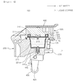
FIG. 4 is a cross-sectional view illustrating a state in which a receiving portion of a capsule housing is closed by a housing cover inFIG. 3 . -
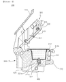
FIGS. 5 and6 are cross-sectional views illustrating operations of the coffee capsule mounting and removal structure according to an exemplary embodiment of the present disclosure. - In order to help provide an understanding of the foregoing features of the present disclosure, a coffee capsule mounting and removal structure according to an exemplary embodiment of the present disclosure will be described in detail hereinafter.
- Hereinafter, embodiments most appropriate to help in an understanding of the technical features of the present invention will be described, the technical features of the present invention are not limited by the described embodiments and merely illustrate the implementation of the present invention through the embodiments described hereinafter. Thus, the present invention can be variably modified within the scope of the present invention through the embodiments described below, and such modifications are within the scope of the present invention. In order to help understand the embodiments described hereinafter, identical or similar reference numerals are used for relevant components among the components having the same function in the respective embodiments in the accompanying drawings.
- Exemplary embodiments of the present disclosure are based on a configuration in which an upper portion of a receiving portion formed in a capsule housing is opened and closed by a housing cover such that a coffee capsule is received therein using a lever member and a plurality of link members.
- As illustrated in an exemplary embodiment illustrated in
FIGS. 1 through 4 , a coffee capsule mounting andremoval structure 100 may include acapsule housing 200, ahousing cover 300, and adriving unit 400. - As illustrated in the exemplary embodiment illustrated in
FIGS. 1 through 4 , a receivingportion 210 may be formed in thecapsule housing 200. Thereceiving portion 210 may be a receiving space in which an upper portion thereof is open as in the illustrated exemplary embodiment. Thus, as illustrated, when a coffee capsule CA with coffee grounds sealed therein may be insertedly received by thereceiving portion 210 through the open upper portion of thereceiving portion 210. - Also, the
capsule housing 200 may be configured such that liquid coffee generated in the coffee capsule CA is discharged outwardly. To this end, as in the exemplary embodiment illustrated inFIGS. 1 through 4 , acoffee outlet 220 connected to the receivingportion 210 may be provided in thecapsule housing 200. - Also, as in the exemplary embodiment illustrated in
FIGS. 3 and4 , acoffee supply member 221 may be provided in the receivingportion 210. An upper portion of thecoffee supply member 221 may be pointed as illustrated. Thus, as illustrated inFIGS. 3 and4 , when the coffee capsule CA is received in the receivingportion 210, a lower portion of the coffee capsule CA may be punched by thecoffee supply member 221. - Also, a
flow hole 221a is formed in the upper portion of thecoffee supply member 221, and acoffee flow channel 221b may be formed in thecoffee supply member 221 and connected to theflow hole 221a. Thecoffee supply member 221 may be connected to thecoffee outlet 220. - Through such a configuration, as described hereinafter and as illustrated in
FIG. 4 , when holt water is supplied to the coffee capsule CA by a hotwater supply member 310 provided in thehousing cover 300, liquid coffee generated in the coffee capsule CA may flow to thecoffee flow channel 221b through theflow hole 221a of thecoffee supply member 221. The liquid coffee may flow in thecoffee flow channel 221b and pass outwardly through thecoffee outlet 220. - As in the exemplary embodiment illustrated in
FIGS. 1 through 4 , one or more grip recesses 211 may be provided on the circumference of the receivingportion 210 of thecapsule housing 200. As in the illustrated exemplary embodiment, two grip recesses 211 may be formed on the circumference of the receivingportion 210 of thecapsule housing 200 in a facing manner. As illustrated inFIGS 1 ,3 , and6 , by virtue of the grip recesses 211, when the upper portion of the receivingportion 210 of thecapsule housing 200 is opened, a user may easily grasp the coffee capsule CA. Also, the user may easily mount the coffee capsule CA into the receivingportion 210 of thecapsule housing 200 or remove the coffee capsule CA therefrom, directly. - Also, as in the exemplary embodiment illustrated in
FIGS. 1 through 4 , asecond sealing member 212 may be provided on the circumference of the receivingportion 210 of thecapsule housing 200. Thesecond sealing member 212 may be insertedly provided in a secondsealing member recess 212a formed on the circumference of the receivingportion 210 of thecapsule housing 200. Thus, even though the grip recesses 211 are provided in thecapsule housing 200, sealing is made between thecapsule housing 200 and thehousing cover 300. - Also, as in the exemplary embodiment illustrated in
FIGS. 1 through 4 , apressing protrusion 330 may be provided in a position of thehousing cover 300 corresponding to thesecond sealing member 212. Accordingly, as illustrated inFIGS. 4 and5 , when thehousing cover 300 closes the upper portion of the receivingportion 210, thepressing protrusion 330 of thehousing cover 300 may press thesecond sealing member 212 of thecapsule housing 200. Thus, sealing between thecapsule housing 200 and thehousing cover 300 may be firmly made by thesecond sealing member 212. - As in the exemplary embodiment illustrated in
FIGS. 1 ,3 , and4 , thehousing cover 300 may be hingedly coupled to thecapsule housing 200. Accordingly, as illustrated inFIGS. 5 and6 , thehousing cover 300 may rotate around ahousing cover 300 hinge connection portion of thecapsule housing 200. - As in the exemplary embodiment illustrated in
FIGS. 1 and2 , a hinge connection protrusion for thehousing cover 300 may be provided in an upper portion of thecapsule housing 200, and a hinge connection hole allowing the hinge connection protrusion for thehousing cover 300 of thecapsule housing 200 to be inserted thereinto may be provided in thehousing cover 300, whereby thehousing cover 300 may be hingedly coupled to the upper portion of thecapsule housing 200. - However, the configuration in which the
housing cover 300 is hingedly coupled to the upper portion of thecapsule housing 200 is not limited to the illustrated exemplary embodiment and any known configuration may be employed as long as thehousing cover 300 is hingedly coupled to thecapsule housing 200. - Also, as illustrated in
FIGS. 4 and5 , thehousing cover 300 may be configured to cover the open upper portion of the receivingportion 210. - As in the exemplary embodiment illustrated in
FIGS. 1 ,3 and4 , the hotwater supply member 310 may be provided in thehousing cover 300. The hotwater supply member 310 may be connected to a hot water source (not shown) by a connection pipe (not shown). - As in the exemplary embodiment illustrated in
FIGS. 1 ,3 , and4 , the hotwater supply member 310 may be pointed. Thus, as illustrated inFIGS. 4 and5 , when thehousing cover 300 covers the upper portion of the receivingportion 210, an upper portion of a capsule coffee CA received in the receivingunit 210 of thecapsule housing 200 may be punched. - Also, as in the exemplary embodiment illustrated in
FIGS. 1 through 4 , the hotwater supply member 310 may include a hotwater supply hole 311 and a hot water flow channel (not shown) connected to the hotwater supply hole 311 and a hot water source. Accordingly, hot water from the hot water source may flow through the hot water flow channel so as to be supplied to the coffee capsule CA through the hotwater supply hole 311. Accordingly, liquid coffee may be generated in the coffee capsule CA. - In order to make liquid coffee generated in the coffee capsule CA taste better, high pressure hot water may be supplied to the coffee capsule CA through the hot
water supply member 310. - As in the exemplary embodiment illustrated in
FIGS. 1 ,3 , and4 , afirst sealing member 320 may be provided in thehousing cover 300. Thefirst sealing member 320 may have a firstsealing member recess 321 formed in thehousing cover 300 as in the illustrated exemplary embodiment. When thehousing cover 300 closes the open upper portion of the receivingportion 210 of thecapsule housing 200 as illustrated inFIGS. 4 and5 , sealing may be primarily made between thecapsule housing 200 and thehousing cover 300 by thefirst sealing member 320. - Also, when the
housing cover 300 closes the upper portion of the receivingportion 210 as illustrated inFIGS. 4 and5 , sealing may be made secondarily between thecapsule housing 200 and thehousing cover 300 by thesecond sealing member 212 provided in thecapsule housing 200. Accordingly, sealing may be firmly made between thecapsule housing 200 and thehousing cover 300. - As in the exemplary embodiment illustrated in
FIGS. 1 through 4 , the drivingunit 400 may include alever member 410 and a plurality oflink members FIGS. 5 and6 , thehousing cover 300 may be configured to be rotated by operations of thelink members lever member 410. Accordingly, the upper portion of the receivingportion 210 of thecapsule housing 200 may be opened and closed as illustrated inFIGS. 5 and6 . Also, the user may easily mount the coffee capsule CA in the receivingportion 210 or remove the coffee capsule CA therefrom directly. - In this manner, since the user may directly mount the coffee capsule CA in the receiving
portion 210 or may remove the coffee capsule CA from the receivingportion 210, there is no need to provide a configuration for mounting and removing the coffee capsule CA in the receivingportion 210. Thus, a space for the configuration for mounting and removing the coffee capsule CA is not required in the receivingportion 210, and thus, the receiving portion may be properly sealed. Thus, since liquid coffee does not remain in the receivingportion 210, the receivingportion 210 may not be contaminated, enhancing a hygienic condition. - The driving
unit 400 may be configured such that thehousing cover 300 will not be opened even though high pressure is exerted on the receivingportion 210, for example, even though high pressure hot water is supplied to the coffee capsule CA so high pressure acts on the receivingportion 210 in a state in which the upper portion of the receivingportion 210 of thecapsule housing 200 is closed by thehousing cover 300 as illustrated inFIGS. 4 and5 . - To this end, as illustrated in
FIGS. 1 through 4 , the drivingunit 400 may include thelever member 410, arotary link member 420, a firstconnection link member 430, and a secondconnection link member 440. - As in the exemplary embodiment illustrated in
FIGS. 1 ,5 , and6 , thelever member 410 may be hingedly coupled to an upper portion of thecapsule housing 200. Accordingly, thelever member 410 may rotate around a hinge connection portion of thelever member 410 of thecapsule housing 200. - A hinge connection protrusion for the
lever member 410 may be provided in an upper portion of thecapsule housing 200 as in the exemplary embodiment illustrated inFIGS. 1 and2 , and a hinge connection hole allowing the hinge connection protrusion for thelever member 410 of thecapsule housing 200 to be inserted thereinto may be provided on thelever member 410, whereby thelever member 410 may be hingedly coupled to the upper portion of thecapsule housing 200. - However, the configuration in which the
lever member 410 is hingedly coupled to the upper portion of thecapsule housing 200 is not limited to the illustrated exemplary embodiment and any known configuration may be employed as long as thelever member 410 is hingedly coupled to thecapsule housing 200. - As in the exemplary embodiment illustrated in
FIGS. 1 ,5 , and6 , one side of therotary link member 420 may be hingedly coupled to a lower portion of thecapsule housing 200. Accordingly, as illustrated inFIGS. 5 and6 , therotary link member 420 may rotate around one side. - As in the exemplary embodiment illustrated in
FIGS. 1 ,5 , and6 , a hinge connection protrusion may be formed on one side of therotary link member 420 and a hinge connection hole allowing the hinge connection protrusion of therotary link member 420 to be inserted thereinto may be formed in a lower portion of thecapsule housing 200, whereby one side of therotary link member 420 may be hingedly coupled to the lower portion of thecapsule housing 200. - However, the configuration in which one side of the
rotary link member 420 is hingedly coupled to the lower portion of thecapsule housing 200 is not limited thereto and any known configuration may be employed as long as the one side of therotary link member 420 is hingedly coupled to the lower portion of thecapsule housing 200. - One side of the first
connection link member 430 may be hingedly coupled to thehousing cover 300 as in the exemplary embodiment illustrated inFIGS. 1 ,5 , and6 . Also, the other side of the firstconnection link member 430 may be hingedly coupled to the other side of therotary link member 420. Accordingly, as illustrated inFIGS. 5 and6 , the firstconnection link member 430 may be moved according to rotation of therotary link member 420 to rotate thehousing cover 300. - As in the exemplary embodiment illustrated in
FIGS. 1 ,5 , and6 , a hinge connection protrusion may be provided in thehousing cover 300 and a hinge connection hole allowing the hinge connection protrusion of thehousing cover 300 to be inserted thereinto may be provided on one side of the firstconnection link member 430, whereby one side of the firstconnection link member 430 may be hingedly coupled to thehousing cover 300. Also, a hinge connection protrusion may be provided on the other side of therotary link member 420 and a hinge connection hole allowing the hinge connection protrusion on the other side of therotary link member 420 to be inserted thereinto may be provided on the other side of the firstconnection link member 430, whereby the other side of the firstconnection link member 430 may be hingedly coupled to the other side of therotary link member 420. - However, the configuration in which one side of the first
connection link member 430 is hingedly coupled to thehousing cover 300 and the other side of the firstconnection link member 430 is hingedly coupled to the other side of therotary link member 420 is not limited to the illustrated exemplary embodiment and any known configuration may be employed as long as one side of the firstconnection link member 430 is hingedly coupled to thehousing cover 300 and the other side of the firstconnection link member 430 is hingedly coupled to the other side of therotary link member 420 - Meanwhile, as in the exemplary embodiment illustrated in
FIGS. 1 and2 , the firstconnection link member 430 may have arecess 431. Such arecess 431 may be caught by aprotrusion 230 formed in thecapsule housing 200 when thehousing cover 300 closes the upper portion of the receivingportion 210 as illustrated inFIG. 5 . Accordingly, when thehousing cover 300 closes the upper portion of the receivingportion 210, thehousing cover 300 may not be lifted up without using thelever member 410 as described hereinafter. - One side of the second
connection link member 440 may be hingedly coupled to thelever member 410 as in the exemplary embodiment illustrated inFIGS. 1 ,5 , and6 . Also, the other side of the secondconnection link member 440 may be hingedly coupled to the other side of therotary link member 420. Accordingly, as illustrated inFIGS. 5 and6 , the secondconnection link member 440 may be moved according to an operation of thelever member 410 to rotate therotary link member 420. - As in the exemplary embodiment illustrated in
FIGS. 1 ,5 , and6 , a hinge connection protrusion may be formed in thelever member 410 and a hinge connection hole allowing the hinge connection protrusion of thelever member 410 to be inserted thereinto may be formed on one side of the secondconnection link member 440, whereby one side of the secondconnection link member 440 may be hingedly coupled to thelever member 410. Also, a hinge connection hole allowing the hinge connection protrusion provided on the other side of therotary link member 420 to be inserted thereinto may be formed on the other side of the secondconnection link member 440, whereby the other side of the secondconnection link member 440 may be hingedly coupled to the other side of therotary link member 420. - However, the configuration in which one side of the second
connection link member 440 is hingedly coupled to thelever member 410 and the other side thereof is hingedly coupled to the other side of therotary link member 420 is not limited to the illustrated exemplary embodiment and any known configuration may be employed as long as one side of the secondconnection link member 440 is hingedly coupled to thelever member 410 and the other side thereof is hingedly coupled to the other side of therotary link member 420. - As in the exemplary embodiment illustrated in
FIGS. 1 ,5 , and6 , therotary link member 420 may be shorter than the firstconnection link member 430 and the secondconnection link member 440. Accordingly, as illustrated inFIGS. 5 and6 , the firstconnection link member 430 is moved according to an operation of thelever member 410, therotary link member 420 rotates, and the secondconnection link member 440 moves to rotate thehousing cover 300. Accordingly, thehousing cover 300 may open and close the upper portion of the receivingportion 210 of thecapsule housing 200. - Meanwhile, as illustrated in
FIG. 5 , when thehousing cover 300 closes the upper portion of the receivingportion 210, a first central virtual line L1 extending from one side of therotary link member 420 to the other side thereof may be positioned between a second central virtual line L2 extending from one side of the firstconnection link member 430 to the other side thereof and a third central virtual line L3 extending from one side of the secondconnection link member 440 to the other side thereof. - Thus, when the
lever member 410 is lifted, a rotation direction of therotary link member 420 according to movement of the secondconnection link member 440 and a rotation direction of therotary link member 420 according to movement of the firstconnection link member 430 based on an amount of force exerted in lifting thehousing cover 300 due to high pressure exerted on the receivingportion 210 of thecapsule housing 200 may be different. - Also, the third central virtual line L3 may be closer to the hinge connection portion of the
lever member 410 than the second central virtual line L2. - Thus, as illustrated in
FIG. 5 , when the upper portion of the receivingportion 210 of thecapsule housing 200 is closed by thehousing cover 300, when thelever member 410 is lifted, the secondconnection link member 440 moves toward the hinge connection portion of thelever member 410, and thus, therotary link member 420 may rotate in a clockwise direction when viewed from the drawing. Thus, thehousing cover 300 may be opened by the firstconnection link member 430. - Also, when the upper portion of the receiving
portion 210 of thecapsule housing 200 is closed by thehousing cover 300 as illustrated inFIG. 5 , when high pressure exerts on the receivingportion 210 of thecapsule housing 200, force acts in a direction in which thehousing cover 300 is lifted. Accordingly, force may acts on the firstconnection link member 430 in a direction in which the firstconnection link member 430 moves away from the hinge connection portion of thelever member 410. Also, force may act on therotary link member 420 in a direction in which therotary link member 420 rotates in a counterclockwise direction when viewed from the drawing. Thus, thehousing cover 300 may further close the upper portion of the receivingportion 210 of thecapsule housing 200 by the firstconnection link member 430. - When the coffee capsule mounting and removal structure according to an exemplary embodiment of the present disclosure described above is used, the upper portion of the receiving portion formed in the capsule housing may be opened and closed by the housing cover such that a coffee capsule is received therein using a lever member and a plurality of link members. Also, a user may easily mount a coffee capsule into the receiving portion of the capsule housing or remove a coffee capsule therefrom, directly. In addition, since a configuration for mounting and removing a coffee capsule is not provided in the receiving portion, the receiving portion may be properly sealed. Moreover, since liquid coffee, or the like, does not remain in the receiving portion, the receiving portion may not be contaminated and a hygienic condition may be enhanced.
- The configuration of the coffee capsule mounting and removal structure according to the exemplary embodiments described above is not limited in application thereof, but the entirety or a portion of the embodiments may be selectively combined to be configured into various modifications.
Claims (13)
- A coffee capsule mounting and removal structure comprising:a capsule housing 200 including a receiving portion 210 allowing a coffee capsule CA with coffee grounds contained therein in a sealed manner to be received therein, and configured to allow liquid coffee generated in the coffee capsule CA to be discharged to the outside;a housing cover 300 hingedly coupled to the capsule housing 200 and covering an open upper portion of the receiving portion 210; anda driving unit 400 including a lever member 410 and a plurality of link members 420, 430, and 440, configured to allow the housing cover 300 to be rotated by the action of the link members 420, 430, and 440 according to an operation of the lever member 410, so as to open and close the upper portion of the receiving portion 210.
- The coffee capsule mounting and removal structure of claim 1, wherein the driving unit 400 is configured such that the housing cover 300 is not opened even in the case that high pressure is exerted on the receiving portion 210 in a state in which the upper portion of the receiving portion 210 is closed by the housing cover 300.
- The coffee capsule mounting and removal structure of claim 2, wherein the driving unit 400 comprises:a lever member 410 hingedly coupled to an upper portion of the capsule housing 200;a rotary link member 420 having one side hingedly coupled to a lower portion of the capsule housing 200;a first connection link member 430 having one side hingedly coupled to the housing cover 300 and the other side hingedly coupled to the other side of the rotary link member 420; anda second connection link member 440 having one side hingedly coupled to the lever member 410 and the other side hingedly coupled to the other side of the rotary link member 420.
- The coffee capsule mounting and removal structure of claim 3, wherein the rotary link member 420 is shorter than the first and second connection link members 430 and 440.
- The coffee capsule mounting and removal structure of claim 4, wherein a first central virtual line L1 extending from one side of the rotary link member 420 to the other side thereof is positioned between a second central virtual line L2 extending from one side of the first connection link member 430 to the other side thereof and a third central virtual line L3 extending from one side of the second connection link member 440 to the other side thereof.
- The coffee capsule mounting and removal structure of claim 5, wherein the third central virtual line L3 may be positioned to be closer to a hinge connection portion of the lever member 410 than the second central virtual line L2.
- The coffee capsule mounting and removal structure of claim 3, wherein a recess 431 is provided in the first connection link member 430 such that the recess 431 is caught by a protrusion 230 provided in the capsule housing 200 when the housing cover 300 closes the upper portion of the receiving portion 210.
- The coffee capsule mounting and removal structure of claim 1, wherein a hot water supply member 310 is provided in the housing cover 300 to punch an upper portion of the coffee capsule CA received in the receiving portion 210 and supply hot water when the upper portion of the receiving portion 210 is closed.
- The coffee capsule mounting and removal structure of claim 8, wherein a first sealing member 320 is provided in the housing cover 300 to perform sealing between the capsule housing 200 and housing cover 300 when the upper portion of the receiving portion 210 is closed.
- The coffee capsule mounting and removal structure of claim 1, wherein a coffee outlet 220 connected to the receiving portion 210 is provided in the capsule housing 200, and
a coffee supply member 221 is provided in the receiving portion 210, punches a lower portion of the coffee capsule CA received in the receiving unit 210 to allow liquid coffee generated in the coffee capsule CA to flow to the coffee outlet 220, and is connected to the coffee outlet 220. - The coffee capsule mounting and removal structure of claim 10, wherein one or more grip recesses 211 are formed on the circumference of the receiving portion 210 of the capsule housing 200 to allow the coffee capsule CA to be easily removed from the receiving portion 210.
- The coffee capsule mounting and removal structure of claim 11, wherein a second sealing member 212 is provided on the circumference of the receiving portion 210 of the capsule housing 200.
- The coffee capsule mounting and removal structure of claim 12, wherein a pressing protrusion 330 pressing the second sealing member 212 is provided in the housing cover 300 in a position corresponding to the second sealing member 212.
Applications Claiming Priority (2)
| Application Number | Priority Date | Filing Date | Title |
|---|---|---|---|
| KR1020120126732A KR102064177B1 (en) | 2012-11-09 | 2012-11-09 | Coffee capsule mounting/dismounting structure |
| PCT/KR2013/009875 WO2014073822A1 (en) | 2012-11-09 | 2013-11-04 | Coffee capsule mounting and removal structure |
Publications (3)
| Publication Number | Publication Date |
|---|---|
| EP2918198A1 true EP2918198A1 (en) | 2015-09-16 |
| EP2918198A4 EP2918198A4 (en) | 2015-11-25 |
| EP2918198B1 EP2918198B1 (en) | 2020-01-08 |
Family
ID=50684870
Family Applications (1)
| Application Number | Title | Priority Date | Filing Date |
|---|---|---|---|
| EP13852909.4A Active EP2918198B1 (en) | 2012-11-09 | 2013-11-04 | Coffee capsule mounting and removal structure |
Country Status (4)
| Country | Link |
|---|---|
| EP (1) | EP2918198B1 (en) |
| KR (1) | KR102064177B1 (en) |
| CN (1) | CN104780817B (en) |
| WO (1) | WO2014073822A1 (en) |
Cited By (2)
| Publication number | Priority date | Publication date | Assignee | Title |
|---|---|---|---|---|
| US20190059630A1 (en) * | 2015-09-17 | 2019-02-28 | Mocoffee Europe Unipessoal, Lda. | Apparatus For Producing A Beverage From A Capsule |
| US10973365B2 (en) | 2014-09-12 | 2021-04-13 | Coway Co., Ltd | Beverage extracting device and water purifier including same |
Families Citing this family (9)
| Publication number | Priority date | Publication date | Assignee | Title |
|---|---|---|---|---|
| KR102292863B1 (en) * | 2014-09-12 | 2021-08-25 | 코웨이 주식회사 | Beverage extracting apparatus |
| KR102292864B1 (en) * | 2014-09-30 | 2021-08-25 | 코웨이 주식회사 | Beverage extracting apparatus and water purifier including the same |
| KR102603456B1 (en) * | 2016-07-22 | 2023-11-17 | 엘지전자 주식회사 | Coffee extraction device |
| CN108784360B (en) * | 2018-07-30 | 2023-10-31 | 宁波三A集团电器有限公司 | Coffee machine brewing structure with fool-proof function |
| US12171361B2 (en) | 2020-12-30 | 2024-12-24 | Sharkninja Operating Llc | Hybrid receptacle beverage brewing system |
| CN115191832A (en) * | 2022-07-29 | 2022-10-18 | 广东亿龙电器科技有限公司 | Electric brewing device |
| USD1048792S1 (en) | 2023-04-12 | 2024-10-29 | Sharkninja Operating Llc | Coffee machine |
| USD1048793S1 (en) | 2023-05-02 | 2024-10-29 | Sharkninja Operating Llc | Coffee machine |
| KR102594263B1 (en) | 2023-05-31 | 2023-10-27 | (주)하나프리 | Capsule coffee extraction basket compatible with various coffee machines |
Family Cites Families (14)
| Publication number | Priority date | Publication date | Assignee | Title |
|---|---|---|---|---|
| US7146904B2 (en) | 2004-01-06 | 2006-12-12 | Whirlpool Corporation | Top load coffee maker with front access water reservoir |
| SI1654966T1 (en) | 2004-10-25 | 2007-04-30 | Nestec Sa | Capsule with sealing means |
| AU2006210110B2 (en) * | 2005-02-07 | 2012-04-19 | Société des Produits Nestlé S.A. | Device for preparing a drink from a capsule by injection of a pressurized fluid and capsule-holder adapted therefore |
| WO2007016977A1 (en) * | 2005-08-05 | 2007-02-15 | Delica Ag | Device for extracting an extraction product contained in a capsule by means of a liquid extraction agent |
| ATE442798T1 (en) * | 2006-05-24 | 2009-10-15 | Nestec Sa | BREWING DEVICE FOR CAPSULES WITH CLOSING MECHANISM WITH VARIABLE GEAR RATIO |
| EP2059156B1 (en) * | 2006-09-07 | 2010-04-21 | Keurig, Incorporated | Method and apparatus for beverage formation |
| ITFI20070028A1 (en) * | 2007-02-07 | 2008-08-08 | Saeco Ipr Ltd | INFUSION DEVICE FOR THE PREPARATION OF DRINKS FROM SINGLE-DOSE CAPSULES WITH A CAPSULES CENTERING DEVICE. |
| EP2155019B1 (en) * | 2007-06-05 | 2011-04-06 | Nestec S.A. | Method for preparing a beverage or liquid food |
| ITFI20070267A1 (en) * | 2007-11-28 | 2009-05-29 | Saeco Ipr Ltd | "INFUSION GROUP FOR THE PREPARATION OF DRINKS FROM SINGLE-DOSE PACKAGES AND MACHINE INCLUDING THE GROUP" |
| EP2238878A1 (en) * | 2009-04-09 | 2010-10-13 | Nestec S.A. | Beverage preparation device having a closing mechanism with force demultiplying means |
| IT1395049B1 (en) * | 2009-08-10 | 2012-09-05 | Capitani Srl | INFUSION GROUP |
| IT1396016B1 (en) * | 2009-10-15 | 2012-11-09 | Swiss Caffe Asia Ltd | INFUSION DEVICE FOR INFUSION AND SIMILAR CAPSULES, PARTICULARLY FOR ESPRESSO AND SIMILAR COFFEE MACHINES. |
| CN201727359U (en) * | 2010-05-07 | 2011-02-02 | 漳州灿坤实业有限公司 | Extraction mechanism of coffee capsule |
| WO2012046195A1 (en) * | 2010-10-08 | 2012-04-12 | Koninklijke Philips Electronics N.V. | Brewing unit with horizontal motion |
-
2012
- 2012-11-09 KR KR1020120126732A patent/KR102064177B1/en active Active
-
2013
- 2013-11-04 EP EP13852909.4A patent/EP2918198B1/en active Active
- 2013-11-04 CN CN201380058027.XA patent/CN104780817B/en active Active
- 2013-11-04 WO PCT/KR2013/009875 patent/WO2014073822A1/en not_active Ceased
Cited By (3)
| Publication number | Priority date | Publication date | Assignee | Title |
|---|---|---|---|---|
| US10973365B2 (en) | 2014-09-12 | 2021-04-13 | Coway Co., Ltd | Beverage extracting device and water purifier including same |
| US20190059630A1 (en) * | 2015-09-17 | 2019-02-28 | Mocoffee Europe Unipessoal, Lda. | Apparatus For Producing A Beverage From A Capsule |
| US10849452B2 (en) * | 2015-09-17 | 2020-12-01 | Mocoffee Europe Unipessoal, Lda. | Apparatus for producing a beverage from a capsule |
Also Published As
| Publication number | Publication date |
|---|---|
| WO2014073822A8 (en) | 2015-05-07 |
| KR20140060410A (en) | 2014-05-20 |
| WO2014073822A1 (en) | 2014-05-15 |
| EP2918198A4 (en) | 2015-11-25 |
| CN104780817B (en) | 2017-05-10 |
| CN104780817A (en) | 2015-07-15 |
| EP2918198B1 (en) | 2020-01-08 |
| KR102064177B1 (en) | 2020-01-09 |
Similar Documents
| Publication | Publication Date | Title |
|---|---|---|
| EP2918198B1 (en) | Coffee capsule mounting and removal structure | |
| KR102449623B1 (en) | Capsule coffee extraction device | |
| KR101897569B1 (en) | Coffee extracting apparatus | |
| EP1755956B1 (en) | Device for forming a vacuum in containers with separable and washable liquid recovery tray | |
| EP3192408B1 (en) | Beverage extracting device and water purifier including same | |
| WO2003059778A3 (en) | Closed capsule with opening mean | |
| EP2340883A3 (en) | Liquid filter arrangement | |
| WO2014158841A8 (en) | Reusable beverage cartridge | |
| JP2016093808A (en) | Oil filter assembly having rotation-type drain pin | |
| TW201026982A (en) | Valve actuating device of a valve, liquid tank of a liquid treatment apparatus, and a liquid treatment apparatus | |
| KR102609844B1 (en) | Elements for activating flow-blocking valves in filtration systems using replaceable cartridges | |
| RU2017142597A (en) | BALL VALVE WITH TOP CONNECTOR, INSTALLATION DEVICE AND METHOD OF ITS APPLICATION | |
| CN103998369B (en) | A kind of device for emptying receptacles | |
| CN202457960U (en) | Pot cover rotating exhaust device | |
| CN102923391A (en) | Barreled wet tissue barrel | |
| KR20150027953A (en) | cover member interworking security water treatment apparatus | |
| CN103349499B (en) | Electric pressure cooker with pressure anti-uncovering device | |
| WO2010105723A3 (en) | Open-ended spinning device | |
| KR100765173B1 (en) | Large capacity filter housing | |
| CN108726725A (en) | A kind of water filtering device | |
| WO2009010663A3 (en) | Electrical household appliance comprising a work receptacle having an orifice for connecting a removable dispensing tap | |
| KR101268065B1 (en) | drain device of water treatment system | |
| KR102307151B1 (en) | Beverage extracting apparatus | |
| CN202864555U (en) | Preservative film cutting device | |
| CN215690282U (en) | Body fluid discharging sealing bag device |
Legal Events
| Date | Code | Title | Description |
|---|---|---|---|
| PUAI | Public reference made under article 153(3) epc to a published international application that has entered the european phase |
Free format text: ORIGINAL CODE: 0009012 |
|
| 17P | Request for examination filed |
Effective date: 20150603 |
|
| AK | Designated contracting states |
Kind code of ref document: A1 Designated state(s): AL AT BE BG CH CY CZ DE DK EE ES FI FR GB GR HR HU IE IS IT LI LT LU LV MC MK MT NL NO PL PT RO RS SE SI SK SM TR |
|
| AX | Request for extension of the european patent |
Extension state: BA ME |
|
| RA4 | Supplementary search report drawn up and despatched (corrected) |
Effective date: 20151023 |
|
| RIC1 | Information provided on ipc code assigned before grant |
Ipc: B65D 85/804 20060101ALI20151019BHEP Ipc: A47J 31/44 20060101AFI20151019BHEP Ipc: A47J 31/36 20060101ALI20151019BHEP |
|
| DAX | Request for extension of the european patent (deleted) | ||
| GRAP | Despatch of communication of intention to grant a patent |
Free format text: ORIGINAL CODE: EPIDOSNIGR1 |
|
| STAA | Information on the status of an ep patent application or granted ep patent |
Free format text: STATUS: GRANT OF PATENT IS INTENDED |
|
| INTG | Intention to grant announced |
Effective date: 20190805 |
|
| GRAS | Grant fee paid |
Free format text: ORIGINAL CODE: EPIDOSNIGR3 |
|
| GRAA | (expected) grant |
Free format text: ORIGINAL CODE: 0009210 |
|
| STAA | Information on the status of an ep patent application or granted ep patent |
Free format text: STATUS: THE PATENT HAS BEEN GRANTED |
|
| AK | Designated contracting states |
Kind code of ref document: B1 Designated state(s): AL AT BE BG CH CY CZ DE DK EE ES FI FR GB GR HR HU IE IS IT LI LT LU LV MC MK MT NL NO PL PT RO RS SE SI SK SM TR |
|
| REG | Reference to a national code |
Ref country code: GB Ref legal event code: FG4D |
|
| REG | Reference to a national code |
Ref country code: CH Ref legal event code: EP |
|
| REG | Reference to a national code |
Ref country code: DE Ref legal event code: R096 Ref document number: 602013064956 Country of ref document: DE |
|
| REG | Reference to a national code |
Ref country code: IE Ref legal event code: FG4D |
|
| REG | Reference to a national code |
Ref country code: AT Ref legal event code: REF Ref document number: 1221613 Country of ref document: AT Kind code of ref document: T Effective date: 20200215 |
|
| REG | Reference to a national code |
Ref country code: CH Ref legal event code: NV Representative=s name: MOINAS AND SAVOYE SARL, CH |
|
| REG | Reference to a national code |
Ref country code: NL Ref legal event code: MP Effective date: 20200108 |
|
| REG | Reference to a national code |
Ref country code: LT Ref legal event code: MG4D |
|
| PG25 | Lapsed in a contracting state [announced via postgrant information from national office to epo] |
Ref country code: LT Free format text: LAPSE BECAUSE OF FAILURE TO SUBMIT A TRANSLATION OF THE DESCRIPTION OR TO PAY THE FEE WITHIN THE PRESCRIBED TIME-LIMIT Effective date: 20200108 Ref country code: NL Free format text: LAPSE BECAUSE OF FAILURE TO SUBMIT A TRANSLATION OF THE DESCRIPTION OR TO PAY THE FEE WITHIN THE PRESCRIBED TIME-LIMIT Effective date: 20200108 Ref country code: NO Free format text: LAPSE BECAUSE OF FAILURE TO SUBMIT A TRANSLATION OF THE DESCRIPTION OR TO PAY THE FEE WITHIN THE PRESCRIBED TIME-LIMIT Effective date: 20200408 Ref country code: FI Free format text: LAPSE BECAUSE OF FAILURE TO SUBMIT A TRANSLATION OF THE DESCRIPTION OR TO PAY THE FEE WITHIN THE PRESCRIBED TIME-LIMIT Effective date: 20200108 Ref country code: RS Free format text: LAPSE BECAUSE OF FAILURE TO SUBMIT A TRANSLATION OF THE DESCRIPTION OR TO PAY THE FEE WITHIN THE PRESCRIBED TIME-LIMIT Effective date: 20200108 Ref country code: PT Free format text: LAPSE BECAUSE OF FAILURE TO SUBMIT A TRANSLATION OF THE DESCRIPTION OR TO PAY THE FEE WITHIN THE PRESCRIBED TIME-LIMIT Effective date: 20200531 |
|
| PG25 | Lapsed in a contracting state [announced via postgrant information from national office to epo] |
Ref country code: GR Free format text: LAPSE BECAUSE OF FAILURE TO SUBMIT A TRANSLATION OF THE DESCRIPTION OR TO PAY THE FEE WITHIN THE PRESCRIBED TIME-LIMIT Effective date: 20200409 Ref country code: LV Free format text: LAPSE BECAUSE OF FAILURE TO SUBMIT A TRANSLATION OF THE DESCRIPTION OR TO PAY THE FEE WITHIN THE PRESCRIBED TIME-LIMIT Effective date: 20200108 Ref country code: SE Free format text: LAPSE BECAUSE OF FAILURE TO SUBMIT A TRANSLATION OF THE DESCRIPTION OR TO PAY THE FEE WITHIN THE PRESCRIBED TIME-LIMIT Effective date: 20200108 Ref country code: HR Free format text: LAPSE BECAUSE OF FAILURE TO SUBMIT A TRANSLATION OF THE DESCRIPTION OR TO PAY THE FEE WITHIN THE PRESCRIBED TIME-LIMIT Effective date: 20200108 Ref country code: BG Free format text: LAPSE BECAUSE OF FAILURE TO SUBMIT A TRANSLATION OF THE DESCRIPTION OR TO PAY THE FEE WITHIN THE PRESCRIBED TIME-LIMIT Effective date: 20200408 Ref country code: IS Free format text: LAPSE BECAUSE OF FAILURE TO SUBMIT A TRANSLATION OF THE DESCRIPTION OR TO PAY THE FEE WITHIN THE PRESCRIBED TIME-LIMIT Effective date: 20200508 |
|
| REG | Reference to a national code |
Ref country code: DE Ref legal event code: R097 Ref document number: 602013064956 Country of ref document: DE |
|
| PG25 | Lapsed in a contracting state [announced via postgrant information from national office to epo] |
Ref country code: RO Free format text: LAPSE BECAUSE OF FAILURE TO SUBMIT A TRANSLATION OF THE DESCRIPTION OR TO PAY THE FEE WITHIN THE PRESCRIBED TIME-LIMIT Effective date: 20200108 Ref country code: CZ Free format text: LAPSE BECAUSE OF FAILURE TO SUBMIT A TRANSLATION OF THE DESCRIPTION OR TO PAY THE FEE WITHIN THE PRESCRIBED TIME-LIMIT Effective date: 20200108 Ref country code: ES Free format text: LAPSE BECAUSE OF FAILURE TO SUBMIT A TRANSLATION OF THE DESCRIPTION OR TO PAY THE FEE WITHIN THE PRESCRIBED TIME-LIMIT Effective date: 20200108 Ref country code: SK Free format text: LAPSE BECAUSE OF FAILURE TO SUBMIT A TRANSLATION OF THE DESCRIPTION OR TO PAY THE FEE WITHIN THE PRESCRIBED TIME-LIMIT Effective date: 20200108 Ref country code: DK Free format text: LAPSE BECAUSE OF FAILURE TO SUBMIT A TRANSLATION OF THE DESCRIPTION OR TO PAY THE FEE WITHIN THE PRESCRIBED TIME-LIMIT Effective date: 20200108 Ref country code: SM Free format text: LAPSE BECAUSE OF FAILURE TO SUBMIT A TRANSLATION OF THE DESCRIPTION OR TO PAY THE FEE WITHIN THE PRESCRIBED TIME-LIMIT Effective date: 20200108 Ref country code: EE Free format text: LAPSE BECAUSE OF FAILURE TO SUBMIT A TRANSLATION OF THE DESCRIPTION OR TO PAY THE FEE WITHIN THE PRESCRIBED TIME-LIMIT Effective date: 20200108 |
|
| PLBE | No opposition filed within time limit |
Free format text: ORIGINAL CODE: 0009261 |
|
| STAA | Information on the status of an ep patent application or granted ep patent |
Free format text: STATUS: NO OPPOSITION FILED WITHIN TIME LIMIT |
|
| REG | Reference to a national code |
Ref country code: AT Ref legal event code: MK05 Ref document number: 1221613 Country of ref document: AT Kind code of ref document: T Effective date: 20200108 |
|
| 26N | No opposition filed |
Effective date: 20201009 |
|
| PG25 | Lapsed in a contracting state [announced via postgrant information from national office to epo] |
Ref country code: AT Free format text: LAPSE BECAUSE OF FAILURE TO SUBMIT A TRANSLATION OF THE DESCRIPTION OR TO PAY THE FEE WITHIN THE PRESCRIBED TIME-LIMIT Effective date: 20200108 |
|
| PG25 | Lapsed in a contracting state [announced via postgrant information from national office to epo] |
Ref country code: SI Free format text: LAPSE BECAUSE OF FAILURE TO SUBMIT A TRANSLATION OF THE DESCRIPTION OR TO PAY THE FEE WITHIN THE PRESCRIBED TIME-LIMIT Effective date: 20200108 Ref country code: PL Free format text: LAPSE BECAUSE OF FAILURE TO SUBMIT A TRANSLATION OF THE DESCRIPTION OR TO PAY THE FEE WITHIN THE PRESCRIBED TIME-LIMIT Effective date: 20200108 |
|
| PG25 | Lapsed in a contracting state [announced via postgrant information from national office to epo] |
Ref country code: MC Free format text: LAPSE BECAUSE OF FAILURE TO SUBMIT A TRANSLATION OF THE DESCRIPTION OR TO PAY THE FEE WITHIN THE PRESCRIBED TIME-LIMIT Effective date: 20200108 |
|
| PG25 | Lapsed in a contracting state [announced via postgrant information from national office to epo] |
Ref country code: LU Free format text: LAPSE BECAUSE OF NON-PAYMENT OF DUE FEES Effective date: 20201104 |
|
| REG | Reference to a national code |
Ref country code: BE Ref legal event code: MM Effective date: 20201130 |
|
| PG25 | Lapsed in a contracting state [announced via postgrant information from national office to epo] |
Ref country code: IE Free format text: LAPSE BECAUSE OF NON-PAYMENT OF DUE FEES Effective date: 20201104 |
|
| PG25 | Lapsed in a contracting state [announced via postgrant information from national office to epo] |
Ref country code: TR Free format text: LAPSE BECAUSE OF FAILURE TO SUBMIT A TRANSLATION OF THE DESCRIPTION OR TO PAY THE FEE WITHIN THE PRESCRIBED TIME-LIMIT Effective date: 20200108 Ref country code: MT Free format text: LAPSE BECAUSE OF FAILURE TO SUBMIT A TRANSLATION OF THE DESCRIPTION OR TO PAY THE FEE WITHIN THE PRESCRIBED TIME-LIMIT Effective date: 20200108 Ref country code: CY Free format text: LAPSE BECAUSE OF FAILURE TO SUBMIT A TRANSLATION OF THE DESCRIPTION OR TO PAY THE FEE WITHIN THE PRESCRIBED TIME-LIMIT Effective date: 20200108 |
|
| PG25 | Lapsed in a contracting state [announced via postgrant information from national office to epo] |
Ref country code: MK Free format text: LAPSE BECAUSE OF FAILURE TO SUBMIT A TRANSLATION OF THE DESCRIPTION OR TO PAY THE FEE WITHIN THE PRESCRIBED TIME-LIMIT Effective date: 20200108 Ref country code: AL Free format text: LAPSE BECAUSE OF FAILURE TO SUBMIT A TRANSLATION OF THE DESCRIPTION OR TO PAY THE FEE WITHIN THE PRESCRIBED TIME-LIMIT Effective date: 20200108 |
|
| PG25 | Lapsed in a contracting state [announced via postgrant information from national office to epo] |
Ref country code: BE Free format text: LAPSE BECAUSE OF NON-PAYMENT OF DUE FEES Effective date: 20201130 |
|
| PGFP | Annual fee paid to national office [announced via postgrant information from national office to epo] |
Ref country code: IT Payment date: 20250924 Year of fee payment: 13 |
|
| PGFP | Annual fee paid to national office [announced via postgrant information from national office to epo] |
Ref country code: GB Payment date: 20250922 Year of fee payment: 13 |
|
| PGFP | Annual fee paid to national office [announced via postgrant information from national office to epo] |
Ref country code: FR Payment date: 20250925 Year of fee payment: 13 |
|
| REG | Reference to a national code |
Ref country code: CH Ref legal event code: U11 Free format text: ST27 STATUS EVENT CODE: U-0-0-U10-U11 (AS PROVIDED BY THE NATIONAL OFFICE) Effective date: 20251201 |
|
| PGFP | Annual fee paid to national office [announced via postgrant information from national office to epo] |
Ref country code: DE Payment date: 20250922 Year of fee payment: 13 |
|
| PGFP | Annual fee paid to national office [announced via postgrant information from national office to epo] |
Ref country code: CH Payment date: 20251201 Year of fee payment: 13 |