EP2917574B1 - Heat-actuated release mechanism - Google Patents
Heat-actuated release mechanism Download PDFInfo
- Publication number
- EP2917574B1 EP2917574B1 EP13717912.3A EP13717912A EP2917574B1 EP 2917574 B1 EP2917574 B1 EP 2917574B1 EP 13717912 A EP13717912 A EP 13717912A EP 2917574 B1 EP2917574 B1 EP 2917574B1
- Authority
- EP
- European Patent Office
- Prior art keywords
- release mechanism
- containment system
- tendon
- container
- retainer
- Prior art date
- Legal status (The legal status is an assumption and is not a legal conclusion. Google has not performed a legal analysis and makes no representation as to the accuracy of the status listed.)
- Active
Links
Images

Classifications
-
- F—MECHANICAL ENGINEERING; LIGHTING; HEATING; WEAPONS; BLASTING
- F03—MACHINES OR ENGINES FOR LIQUIDS; WIND, SPRING, OR WEIGHT MOTORS; PRODUCING MECHANICAL POWER OR A REACTIVE PROPULSIVE THRUST, NOT OTHERWISE PROVIDED FOR
- F03G—SPRING, WEIGHT, INERTIA OR LIKE MOTORS; MECHANICAL-POWER PRODUCING DEVICES OR MECHANISMS, NOT OTHERWISE PROVIDED FOR OR USING ENERGY SOURCES NOT OTHERWISE PROVIDED FOR
- F03G7/00—Mechanical-power-producing mechanisms, not otherwise provided for or using energy sources not otherwise provided for
- F03G7/06—Mechanical-power-producing mechanisms, not otherwise provided for or using energy sources not otherwise provided for using expansion or contraction of bodies due to heating, cooling, moistening, drying or the like
- F03G7/061—Mechanical-power-producing mechanisms, not otherwise provided for or using energy sources not otherwise provided for using expansion or contraction of bodies due to heating, cooling, moistening, drying or the like characterised by the actuating element
- F03G7/0614—Mechanical-power-producing mechanisms, not otherwise provided for or using energy sources not otherwise provided for using expansion or contraction of bodies due to heating, cooling, moistening, drying or the like characterised by the actuating element using shape memory elements
-
- F—MECHANICAL ENGINEERING; LIGHTING; HEATING; WEAPONS; BLASTING
- F03—MACHINES OR ENGINES FOR LIQUIDS; WIND, SPRING, OR WEIGHT MOTORS; PRODUCING MECHANICAL POWER OR A REACTIVE PROPULSIVE THRUST, NOT OTHERWISE PROVIDED FOR
- F03G—SPRING, WEIGHT, INERTIA OR LIKE MOTORS; MECHANICAL-POWER PRODUCING DEVICES OR MECHANISMS, NOT OTHERWISE PROVIDED FOR OR USING ENERGY SOURCES NOT OTHERWISE PROVIDED FOR
- F03G7/00—Mechanical-power-producing mechanisms, not otherwise provided for or using energy sources not otherwise provided for
- F03G7/06—Mechanical-power-producing mechanisms, not otherwise provided for or using energy sources not otherwise provided for using expansion or contraction of bodies due to heating, cooling, moistening, drying or the like
- F03G7/063—Mechanical-power-producing mechanisms, not otherwise provided for or using energy sources not otherwise provided for using expansion or contraction of bodies due to heating, cooling, moistening, drying or the like characterised by the mechanic interaction
- F03G7/0631—One-way operation, e.g. release mechanism
-
- F—MECHANICAL ENGINEERING; LIGHTING; HEATING; WEAPONS; BLASTING
- F03—MACHINES OR ENGINES FOR LIQUIDS; WIND, SPRING, OR WEIGHT MOTORS; PRODUCING MECHANICAL POWER OR A REACTIVE PROPULSIVE THRUST, NOT OTHERWISE PROVIDED FOR
- F03G—SPRING, WEIGHT, INERTIA OR LIKE MOTORS; MECHANICAL-POWER PRODUCING DEVICES OR MECHANISMS, NOT OTHERWISE PROVIDED FOR OR USING ENERGY SOURCES NOT OTHERWISE PROVIDED FOR
- F03G7/00—Mechanical-power-producing mechanisms, not otherwise provided for or using energy sources not otherwise provided for
- F03G7/06—Mechanical-power-producing mechanisms, not otherwise provided for or using energy sources not otherwise provided for using expansion or contraction of bodies due to heating, cooling, moistening, drying or the like
- F03G7/064—Mechanical-power-producing mechanisms, not otherwise provided for or using energy sources not otherwise provided for using expansion or contraction of bodies due to heating, cooling, moistening, drying or the like characterised by its use
-
- F—MECHANICAL ENGINEERING; LIGHTING; HEATING; WEAPONS; BLASTING
- F16—ENGINEERING ELEMENTS AND UNITS; GENERAL MEASURES FOR PRODUCING AND MAINTAINING EFFECTIVE FUNCTIONING OF MACHINES OR INSTALLATIONS; THERMAL INSULATION IN GENERAL
- F16B—DEVICES FOR FASTENING OR SECURING CONSTRUCTIONAL ELEMENTS OR MACHINE PARTS TOGETHER, e.g. NAILS, BOLTS, CIRCLIPS, CLAMPS, CLIPS OR WEDGES; JOINTS OR JOINTING
- F16B2200/00—Constructional details of connections not covered for in other groups of this subclass
- F16B2200/77—Use of a shape-memory material
Definitions
- the invention is in the field of mechanical release mechanisms.
- US 2010/0139264 A1 discloses a separating apparatus that comprises a pre-strained member formed from a shape memory alloy that is configured to separate upon application of heat.
- JP 2006 316830 A discloses that to provide a compacter fastening structure capable of easily cancelling fastening between fastened members while securing sufficient force of fastening the fastened members to each other, in the fastening structure, a split stopper is applied onto the outer peripheries of first and second nut pieces and the split stopper and the nut pieces are fitted into a ring member until the nut pieces are integrated therewith to form a clamping member which is connectable to a bolt.
- the ring member is formed of a shape memory material which produces contractive deforming force with heat, and the ring member has a vulnerable portion breakable when the contractive deforming force is produced. The breakage of the vulnerable portion cancels fastening between the first and second fastened members.
- EP 2 341 522 A1 discloses a fusing device comprising a core portion, a first terminal, a second terminal, and at least a thermal expanding element provided between the first flange and the second flange with two ends thereof against the first and second flanges respectively, which is configured to break the core portion during thermal expanding.
- the present disclosure provides a containment system comprising: a container; a lid; and a release mechanism comprising: a first member; a second member; and a separable element mechanically coupled to the first member and the second member; wherein, the separable element separates when heated to a predetermined temperature, releasing the first member from the second member, and separating the first member from the second member; wherein the release mechanism separably couples the lid and the container together to close the container; wherein the first member remains coupled to the lid when the release mechanism is separated; wherein the second member remains coupled to the container when the release mechanism is separated; wherein the second member includes a tendon that is rotatably coupled to the container; and wherein the release mechanism further includes a tendon retainer, with the tendon held between the first member and the tendon retainer, prior to separation of the release mechanism; and further comprising a latch that is rotatably coupled to the first member; wherein opposite ends of the separable element are fixedly attached to the tendon retainer and
- a release mechanism includes a separable plastic element that separates when heated, releasing the mechanism.
- a release mechanism includes a breakable shape memory alloy element.
- a release mechanism passively releases a mechanically coupling as a result of a temperature rise.
- the release mechanism includes a breakable element, such as a shape memory alloy (SMA) element, that is configured to break when the element is heated to a predetermined temperature.
- SMA shape memory alloy
- the breakage of the breakable element releases a mechanical coupling, such as a coupling holding a lid onto a container.
- the release mechanism may be part of a handle or other device to close the container.
- the release mechanism may have a mechanical load on it prior to release, a load that in part passes through the breakable element. Most of the load may pass through one or more other members of the release mechanism, providing the force for separation after the release mechanism is triggered.
- the release mechanism may be used to provide a passive way of releasing a mechanical coupling in response to some sort of heating.
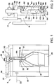
- Fig. 1 shows part of a containment system 8 that includes a release mechanism 10 that is part of a handle 12 for closing a lid 14 of a container 16, and for mechanically securing the lid 14 to the container 16.
- the handle 12 which may be part of the container 16 and/or the lid 14, is used to secure the lid 14 by pivoting relative to the lid 14 and the container 16.
- the container 16 may be a rectangular box, or more generally a container of any suitable shape. Multiple of the handles 12 may be located around a perimeter of the container 16, to secure the lid 14 to the container 16 at multiple locations.
- a grip portion 18 of the handle 12 is coupled to the release mechanism 10 with a pin 20, which allows the release mechanism 10 to pivot relative to the grip portion 18.
- the grip portion 18 is in turn pivotally coupled to the container 16, allowing the grip portion 18 to pivot about a pivot axis 22 in the container 16.
- the release mechanism 10 includes a stud 30 that has a threaded shaft 32, with a half-barrel nut 36 threaded onto it.
- the half-barrel nut 36 engages a corresponding curved recess 38 in the lid 14.
- the handle 12 is engaged by rotating the grip portion 18 into a recess 39 in the container 16, the nut 36 is pulled down against the top of the lid 14. This pulls the lid 14 tight against the container 16, with a force running through the handle 12 while the handle 12 is engaged.
- the container 16 may enclose any of a variety of items.
- the container 16 encloses rocket motors, or devices containing rocket motors.
- rocket motors or devices containing rocket motors.
- One issue with storing rocket motors is providing protection against explosion, should the fuel in any of the rocket motors begin to burn. If the container 16 remains closed then pressure can build up, possibly triggering an explosion. The risk of a catastrophic outcome is greatly reduced if the pressure build-up can be relieved, for example by allowing the lid 14 to at least partially separate from the container 16. Therefore the release mechanism 10 is configured to separate the handle's mechanical connection when sufficient heat is applied to the release mechanism 10. Whether the rocket motors burn in a slow cook or fast cook process, heat is generated which heats the container 16 and the handle 12. This heating can be used as a passive trigger to release the lid 14 from the container through the release mechanism 10.
- the release mechanism 10 advantageously does not require any active sensors or power to trigger the release of the lid 14 from the container 16.
- the release mechanism 10 includes a tendon 40 that is connected to the handle grip portion 18 ( Fig. 1 ).
- the tendon 40 has a hole 44 that receives the pin 20 ( Fig. 1 ) coupling together the tendon 40 and the grip portion 18.
- the pin connection 20 allows for pivoting between the tendon 40 and the grip portion 18.
- the inner member 50 is a continuous monolithic piece that includes the stud 30 that receives the half-barrel nut 36 ( Fig. 1 ). As an alternative, the inner member 50 may be in multiple pieces.
- the member 50 has a recess 58 on its inner surface 60.
- the recess 58 receives a portion 64 of the tendon 40, the same portion of the tendon 40 that has the pin-receiving hole 44.
- the tendon retainer 52 on the opposite side of the tendon 40, includes a protrusion 68 that engages a corresponding recess 70 in the tendon 40. The engagement of the tendon 40 by the tendon retainer 52 prevents the tendon 40 from sliding out of engagement within the release mechanism 10. The engagement also helps transmit loads within the release mechanism 10.
- the tendon retainer 52 is able to pivot relative to the inner member 50 at a joint 76 between the two.
- the joint 76 allows the tendon retainer 52 to rotate relative to the inner member 50 when the release mechanism is released, to allow the tendon 40 to escape from between the inner member 50 and the tendon retainer 52.
- the mechanism 10 is released, the inner member 50 and the tendon retainer 52 remain coupled to the lid 14 ( Fig. 1 ), and the tendon 40 remains with the container 16 ( Fig. 1 ).
- the release of the mechanism 10 allows the lid 14 to at least locally separate from the container 16. This may allow release of pressure that may have built up within the container 16, and may aid in preventing further pressure build up in the container 16.
- the release mechanism 10 also includes a separable element 80 that breaks or otherwise separates when heated, in order to release the engagement of the parts of the mechanism 10.
- the separable element 80 in the illustrated embodiment is a shape memory alloy element that is configured to break when heated.
- the element 80 has a pair of indentations or notches 82 ( Fig. 1 ) that reduce the width of the element 80 at a given separation location 84 ( Fig. 1 ). The reduction in width produces a weak point in the element 80, where the element 80 would preferentially break.
- the notches 82 are shown as semi-circles, but alternatively may be any of a variety of other shapes. Other types of preferential weakening are also possible, including scoring, thinning, and local changes in material composition and/or other characteristics.
- the separable element 80 is secured at opposite ends by a pair of clamps 86 and 88.
- the upper clamp 86 secures the upper end of the element 80 to the tendon retainer 52.
- the lower clamp 88 secures the lower end of the element 80 to a hinged load reduction latch 90.
- the clamps 86 and 88 may be metal blocks that are screwed or bolted (or otherwise fastened) onto the tendon retainer 52 and the load reduction latch 90, respectively.
- the separable element 80 may be folded over or otherwise engaged with the clamps 86 and 88, to locally increase the strength of the separable element 80 in the vicinity of the clamps 86 and 88, to avoid having the separable element 80 be locally weakened in the vicinity of the clamps 86 and 88.
- the latch 90 aids in retaining the mechanism 10 together, prior to release by separation (severing) of the separable element 80.
- the latch 90 is coupled to the inner member 50 by a pin 94, at a lower end 96 of the inner member 50. This allows the latch 90 to rotate relative to the inner member 50, about the pin 94.
- the latch 90 Prior to release of the mechanism 10, the latch 90 fits around a lower end 98 of the tendon retainer 52. This keeps the tendon retainer lower end 98 held against the inner member lower end 96.
- the tendon retainer lower end 98 has a roller 100, which presses against the latch 90 prior to release of the mechanism 10.
- the roller 100 aids in allowing movement between the tendon retainer 52 and the latch 90, when the mechanism 10 is released. As an alternative, the roller 100 may be omitted if desired.
- the mechanism 10 is loaded when the handle 12 ( Fig. 1 ) is closed, providing a force to hold the lid 14 ( Fig. 1 ) against the top of the container 16 ( Fig. 1 ).
- the load also provides a mechanical force to separate the lid 14 from the container 16 when the mechanism 10 is released.
- the path through the tendon retainer 52 also puts a tension load on the separable element 80. It is desirable to provide enough load on the separable element 80 so that the separable element 80 is in tension, but to avoid overloading the separable element 80 in tension, since overloading could cause undesired separation, which would result in release of the mechanism 10.
- the release mechanism 10 has a separable element tensioner 104 that is used to control the tension in the separable element 80.
- the tensioner 104 is a set screw that engages a threaded hole in the latch 90, to allow a tip of the set screw to press against an end surface of the tendon retainer 52. Turing the set screw positions the latch 90 relative to the tendon retainer 52, adjusting the tension in the separable element 80.
- the separable element 80 may be made of any of a variety of materials that exhibit shape memory properties, such as shape memory alloys.
- Shape memory alloys undergo a temperature related phase change that is characterized by the memory of a mechanical configuration imposed on the material at an annealing temperature. When the shape memory alloy is below some lower temperature, the alloy possesses a particular crystal structure whereby it may be deformed into an arbitrary shape with relative ease. Upon heating the alloy above a higher temperature, the alloy undergoes a change in crystal structure and the shape memory effect is manifested by a resumption of the originally imparted shape, representing the onset of a restoring stress. Further details regarding the behavior of shape memory materials may be found in co-owned U.S. Patent Pub. 2010/0139264 .
- suitable shape memory alloys include nickel-titanium alloys (e.g., Nitinol), titanium-nickel alloys, copper-zinc-aluminum alloys, copper aluminum nickel alloys, nickel titanium hafnium alloys, and other shape memory alloys.
- Nitinol nickel-titanium alloys
- titanium-nickel alloys titanium-nickel alloys
- copper-zinc-aluminum alloys copper aluminum nickel alloys
- nickel titanium hafnium alloys nickel titanium hafnium alloys
- other shape memory alloys include nickel-titanium alloys (e.g., Nitinol), titanium-nickel alloys, copper-zinc-aluminum alloys, copper aluminum nickel alloys, nickel titanium hafnium alloys, and other shape memory alloys.
- the separable element 80 may be imparted with a "remembered" set shape that is far different from the shape it later has when installed in the release mechanism 10.
- the element 80 may be element stretched or strained from its original shape.
- the separable element 80 is heated, such as from slow or fast combustion of external environmental elements, the separable element 80 undergoes a force as it tries to contract or otherwise return to its remembered set shape. This puts a stress on the separable element 80. With the indentations or notches 82, this stress causes the separable element 80 to break at the weakened location 84.
- the dimensions and other characteristics of the separable element 80, and of its indentions or notches 82, and its weakened location 84, may be selected to achieve breakage of the element 80 (and release of the mechanism 10) when heating occurs that is associated with a desired release of the mechanism 10. For example, combustion of the item or items in the vicinity of the container 16 will be expected to cause a certain amount of heating, and the element 80 may be configured to release the mechanism 10 when an amount of heating occurs that is associated with a need to provide some pressure release by loosening the lid 14.
- the separable element 80 alternatively may include another sort of material, a material that separates by a different mechanism.
- the separable element 80 may be a plastic material that melts or weakens when heated. This melting or weakening results in breaking or otherwise separating of parts of the plastic element, releasing the mechanism 10.
- a plastic material for the separable element 80 may be selected to achieve release of the mechanism at a desired heating.
- the other parts of the mechanism may be made of any of a variety of suitable materials. Suitable stainless steel is an example of a suitable material.
- Fig. 3-5 illustrate release of the mechanism 10.
- Fig. 3 shows the separable element 80 being heated, as shown at 120.
- the heating may be by any of a variety of mechanisms, such as by conduction through the mechanism 10, or by radiation or convention from the container 16 ( Fig. 1 ) or the surrounding environment.
- Fig. 4 shows the mechanism 10 immediately following separation of the element 80.
- the latch 90 and the tendon retainer 52 separate from one another, each rotating relative to the inner member 50.
- the roller 100 on the tendon retainer 52 helps prevent binding between the tendon retainer 52 and the latch 90.
- Fig. 6 schematically shows a generalized system 200 in which a release mechanism 210 couples together a pair of members 212 and 214.
- the mechanism 210 may have some of the same characteristics as the mechanism 10 ( Fig. 1 ) described above.
- the mechanism 210 may have a separable element that is similar in configuration and function to the separable element 80 ( Fig. 2 ).
- other parts of the mechanism 210 may have a different configuration as to how the mechanism 210 is held together prior to release, and to how the parts of the mechanism 210 release from one another after separation of the separable element.
- the members 212 and 214 may be any sort of parts or devices that change position and/or function (or other characteristics) when the release mechanism 210 is released.
- one or both members 212 and 214 may be parts of a boiler or other device that would benefit from release or pressure (or other change in operation) when overheating. In such a situation the release of the mechanism 210 may trigger opening of a relief mechanism, such as a venting door, to relieve pressure within the boiler or other device.
- release the mechanism 210 may cause closing of one or more fire doors that may be, or may be coupled to, the members 212 and 214. Heating from a fire may release the mechanism 210, resulting directly or indirectly in closing the fire doors.
- the mechanisms 10 and 210 have the advantage of being passive devices actuated by heat. No power is required for operation of the release mechanisms, nor is there any need for a temperature or other sensor.
Landscapes
- Engineering & Computer Science (AREA)
- Chemical & Material Sciences (AREA)
- Combustion & Propulsion (AREA)
- Mechanical Engineering (AREA)
- General Engineering & Computer Science (AREA)
- Closures For Containers (AREA)
Description
- The invention is in the field of mechanical release mechanisms.
- Many situations require activation of a mechanism in response to heating, or in response to a condition that accompanies heating. Examples include pressure release for an overheating boiler, a fire in a storage area for munitions, or a fire or other pressure-increasing event within a storage container. Active actuation systems, for example with a powered actuator coupled to a temperature or heat sensor, have been tried in the past to detect and react to such events, but there are shortcomings in such approaches.
-
US 2010/0139264 A1 discloses a separating apparatus that comprises a pre-strained member formed from a shape memory alloy that is configured to separate upon application of heat. -
JP 2006 316830 A -
EP 2 341 522 A1 discloses a fusing device comprising a core portion, a first terminal, a second terminal, and at least a thermal expanding element provided between the first flange and the second flange with two ends thereof against the first and second flanges respectively, which is configured to break the core portion during thermal expanding. - According to an aspect the present disclosure provides a containment system comprising: a container; a lid; and a release mechanism comprising: a first member; a second member; and a separable element mechanically coupled to the first member and the second member; wherein, the separable element separates when heated to a predetermined temperature, releasing the first member from the second member, and separating the first member from the second member; wherein the release mechanism separably couples the lid and the container together to close the container; wherein the first member remains coupled to the lid when the release mechanism is separated; wherein the second member remains coupled to the container when the release mechanism is separated; wherein the second member includes a tendon that is rotatably coupled to the container; and wherein the release mechanism further includes a tendon retainer, with the tendon held between the first member and the tendon retainer, prior to separation of the release mechanism; and further comprising a latch that is rotatably coupled to the first member; wherein opposite ends of the separable element are fixedly attached to the tendon retainer and the latch, respectively.
- According to still another aspect of the invention, a release mechanism includes a separable plastic element that separates when heated, releasing the mechanism.
- According to a further aspect of the invention, a release mechanism includes a breakable shape memory alloy element.
- To the accomplishment of the foregoing and related ends, the invention comprises the features hereinafter fully described and particularly pointed out in the claims. The following description and the annexed drawings set forth in detail certain illustrative embodiments of the invention.
- The annexed drawings, which are not necessarily to scale, show various aspects of the invention.
-
Fig. 1 is an oblique view of part of a system that includes a release mechanism in accordance with an embodiment of the present invention. -
Fig. 2 is a cross-section view of the release mechanism ofFig. 1 . -
Fig. 3 is a cross-section view of a first step in release of the release mechanism ofFig. 1 . -
Fig. 4 is a cross-section view of a second step in release of the release mechanism ofFig. 1 . -
Fig. 5 is a cross-section view of a third step in release of the release mechanism ofFig. 1 . -
Fig. 6 is a schematic view of an alternate embodiment system that includes a release mechanism. - A release mechanism passively releases a mechanically coupling as a result of a temperature rise. The release mechanism includes a breakable element, such as a shape memory alloy (SMA) element, that is configured to break when the element is heated to a predetermined temperature. The breakage of the breakable element releases a mechanical coupling, such as a coupling holding a lid onto a container. The release mechanism may be part of a handle or other device to close the container. The release mechanism may have a mechanical load on it prior to release, a load that in part passes through the breakable element. Most of the load may pass through one or more other members of the release mechanism, providing the force for separation after the release mechanism is triggered. The release mechanism may be used to provide a passive way of releasing a mechanical coupling in response to some sort of heating.
-
Fig. 1 shows part of acontainment system 8 that includes arelease mechanism 10 that is part of ahandle 12 for closing alid 14 of acontainer 16, and for mechanically securing thelid 14 to thecontainer 16. Thehandle 12, which may be part of thecontainer 16 and/or thelid 14, is used to secure thelid 14 by pivoting relative to thelid 14 and thecontainer 16. Thecontainer 16 may be a rectangular box, or more generally a container of any suitable shape. Multiple of thehandles 12 may be located around a perimeter of thecontainer 16, to secure thelid 14 to thecontainer 16 at multiple locations. - A
grip portion 18 of thehandle 12 is coupled to therelease mechanism 10 with apin 20, which allows therelease mechanism 10 to pivot relative to thegrip portion 18. Thegrip portion 18 is in turn pivotally coupled to thecontainer 16, allowing thegrip portion 18 to pivot about apivot axis 22 in thecontainer 16. - The
release mechanism 10 includes astud 30 that has a threadedshaft 32, with a half-barrel nut 36 threaded onto it. The half-barrel nut 36 engages a correspondingcurved recess 38 in thelid 14. When thehandle 12 is engaged by rotating thegrip portion 18 into a recess 39 in thecontainer 16, thenut 36 is pulled down against the top of thelid 14. This pulls thelid 14 tight against thecontainer 16, with a force running through thehandle 12 while thehandle 12 is engaged. - The
container 16 may enclose any of a variety of items. In one embodiment, thecontainer 16 encloses rocket motors, or devices containing rocket motors. One issue with storing rocket motors is providing protection against explosion, should the fuel in any of the rocket motors begin to burn. If thecontainer 16 remains closed then pressure can build up, possibly triggering an explosion. The risk of a catastrophic outcome is greatly reduced if the pressure build-up can be relieved, for example by allowing thelid 14 to at least partially separate from thecontainer 16. Therefore therelease mechanism 10 is configured to separate the handle's mechanical connection when sufficient heat is applied to therelease mechanism 10. Whether the rocket motors burn in a slow cook or fast cook process, heat is generated which heats thecontainer 16 and thehandle 12. This heating can be used as a passive trigger to release thelid 14 from the container through therelease mechanism 10. Therelease mechanism 10 advantageously does not require any active sensors or power to trigger the release of thelid 14 from thecontainer 16. - Referring now in addition to
Fig. 2 , therelease mechanism 10 includes atendon 40 that is connected to the handle grip portion 18 (Fig. 1 ). Thetendon 40 has ahole 44 that receives the pin 20 (Fig. 1 ) coupling together thetendon 40 and thegrip portion 18. Thepin connection 20 allows for pivoting between thetendon 40 and thegrip portion 18. - When the
release mechanism 10 is intact (prior to release), thetendon 40 is between aninner member 50 and atendon retainer 52. Theinner member 50 is a continuous monolithic piece that includes thestud 30 that receives the half-barrel nut 36 (Fig. 1 ). As an alternative, theinner member 50 may be in multiple pieces. Themember 50 has arecess 58 on its inner surface 60. Therecess 58 receives aportion 64 of thetendon 40, the same portion of thetendon 40 that has the pin-receivinghole 44. Thetendon retainer 52, on the opposite side of thetendon 40, includes aprotrusion 68 that engages acorresponding recess 70 in thetendon 40. The engagement of thetendon 40 by thetendon retainer 52 prevents thetendon 40 from sliding out of engagement within therelease mechanism 10. The engagement also helps transmit loads within therelease mechanism 10. - The
tendon retainer 52 is able to pivot relative to theinner member 50 at ajoint 76 between the two. Thejoint 76 allows thetendon retainer 52 to rotate relative to theinner member 50 when the release mechanism is released, to allow thetendon 40 to escape from between theinner member 50 and thetendon retainer 52. When themechanism 10 is released, theinner member 50 and thetendon retainer 52 remain coupled to the lid 14 (Fig. 1 ), and thetendon 40 remains with the container 16 (Fig. 1 ). As explained in greater detail later, the release of themechanism 10 allows thelid 14 to at least locally separate from thecontainer 16. This may allow release of pressure that may have built up within thecontainer 16, and may aid in preventing further pressure build up in thecontainer 16. - The
release mechanism 10 also includes aseparable element 80 that breaks or otherwise separates when heated, in order to release the engagement of the parts of themechanism 10. Theseparable element 80 in the illustrated embodiment is a shape memory alloy element that is configured to break when heated. Theelement 80 has a pair of indentations or notches 82 (Fig. 1 ) that reduce the width of theelement 80 at a given separation location 84 (Fig. 1 ). The reduction in width produces a weak point in theelement 80, where theelement 80 would preferentially break. Thenotches 82 are shown as semi-circles, but alternatively may be any of a variety of other shapes. Other types of preferential weakening are also possible, including scoring, thinning, and local changes in material composition and/or other characteristics. - The
separable element 80 is secured at opposite ends by a pair ofclamps upper clamp 86 secures the upper end of theelement 80 to thetendon retainer 52. Thelower clamp 88 secures the lower end of theelement 80 to a hingedload reduction latch 90. Theclamps tendon retainer 52 and theload reduction latch 90, respectively. Theseparable element 80 may be folded over or otherwise engaged with theclamps separable element 80 in the vicinity of theclamps separable element 80 be locally weakened in the vicinity of theclamps - The
latch 90 aids in retaining themechanism 10 together, prior to release by separation (severing) of theseparable element 80. Thelatch 90 is coupled to theinner member 50 by apin 94, at alower end 96 of theinner member 50. This allows thelatch 90 to rotate relative to theinner member 50, about thepin 94. Prior to release of themechanism 10, thelatch 90 fits around alower end 98 of thetendon retainer 52. This keeps the tendon retainerlower end 98 held against the inner memberlower end 96. The tendon retainerlower end 98 has aroller 100, which presses against thelatch 90 prior to release of themechanism 10. Theroller 100 aids in allowing movement between thetendon retainer 52 and thelatch 90, when themechanism 10 is released. As an alternative, theroller 100 may be omitted if desired. - The
mechanism 10 is loaded when the handle 12 (Fig. 1 ) is closed, providing a force to hold the lid 14 (Fig. 1 ) against the top of the container 16 (Fig. 1 ). The load also provides a mechanical force to separate thelid 14 from thecontainer 16 when themechanism 10 is released. There is a load path passing through themechanism 10, through the tendon retain 52. The path through thetendon retainer 52 also puts a tension load on theseparable element 80. It is desirable to provide enough load on theseparable element 80 so that theseparable element 80 is in tension, but to avoid overloading theseparable element 80 in tension, since overloading could cause undesired separation, which would result in release of themechanism 10. Therefore some of the load (e.g., less than half of the load) on themechanism 10 may be directed through theseparable element 80. Therelease mechanism 10 has aseparable element tensioner 104 that is used to control the tension in theseparable element 80. Thetensioner 104 is a set screw that engages a threaded hole in thelatch 90, to allow a tip of the set screw to press against an end surface of thetendon retainer 52. Turing the set screw positions thelatch 90 relative to thetendon retainer 52, adjusting the tension in theseparable element 80. - The
separable element 80 may be made of any of a variety of materials that exhibit shape memory properties, such as shape memory alloys. Shape memory alloys undergo a temperature related phase change that is characterized by the memory of a mechanical configuration imposed on the material at an annealing temperature. When the shape memory alloy is below some lower temperature, the alloy possesses a particular crystal structure whereby it may be deformed into an arbitrary shape with relative ease. Upon heating the alloy above a higher temperature, the alloy undergoes a change in crystal structure and the shape memory effect is manifested by a resumption of the originally imparted shape, representing the onset of a restoring stress. Further details regarding the behavior of shape memory materials may be found in co-ownedU.S. Patent Pub. 2010/0139264 . Examples of suitable shape memory alloys include nickel-titanium alloys (e.g., Nitinol), titanium-nickel alloys, copper-zinc-aluminum alloys, copper aluminum nickel alloys, nickel titanium hafnium alloys, and other shape memory alloys. - The
separable element 80 may be imparted with a "remembered" set shape that is far different from the shape it later has when installed in therelease mechanism 10. In installing theelement 80 in therelease mechanism 10, theelement 80 may be element stretched or strained from its original shape. When theseparable element 80 is heated, such as from slow or fast combustion of external environmental elements, theseparable element 80 undergoes a force as it tries to contract or otherwise return to its remembered set shape. This puts a stress on theseparable element 80. With the indentations ornotches 82, this stress causes theseparable element 80 to break at the weakenedlocation 84. The dimensions and other characteristics of theseparable element 80, and of its indentions ornotches 82, and its weakenedlocation 84, may be selected to achieve breakage of the element 80 (and release of the mechanism 10) when heating occurs that is associated with a desired release of themechanism 10. For example, combustion of the item or items in the vicinity of thecontainer 16 will be expected to cause a certain amount of heating, and theelement 80 may be configured to release themechanism 10 when an amount of heating occurs that is associated with a need to provide some pressure release by loosening thelid 14. - The
separable element 80 alternatively may include another sort of material, a material that separates by a different mechanism. For example theseparable element 80 may be a plastic material that melts or weakens when heated. This melting or weakening results in breaking or otherwise separating of parts of the plastic element, releasing themechanism 10. A plastic material for theseparable element 80 may be selected to achieve release of the mechanism at a desired heating. - The other parts of the mechanism (and the
container 16 and the lid 14) may be made of any of a variety of suitable materials. Suitable stainless steel is an example of a suitable material. -
Fig. 3-5 illustrate release of themechanism 10.Fig. 3 shows theseparable element 80 being heated, as shown at 120. The heating may be by any of a variety of mechanisms, such as by conduction through themechanism 10, or by radiation or convention from the container 16 (Fig. 1 ) or the surrounding environment. -
Fig. 4 shows themechanism 10 immediately following separation of theelement 80. Thelatch 90 and thetendon retainer 52 separate from one another, each rotating relative to theinner member 50. Theroller 100 on thetendon retainer 52 helps prevent binding between thetendon retainer 52 and thelatch 90. - The rotation continues until the
tendon retainer 52 becomes fully disengaged from thetendon 40, as illustrated inFig. 5 . Theinner member 50, thetendon retainer 52, and thelatch 50 are all pulled upward, along with the lid 14 (Fig. 1 ). These parts of themechanism 10 become separated from thetendon 40, which remains coupled to the container 16 (Fig. 1 ). The separation of the parts of themechanism 10 allows thelid 14 to become mechanically decoupled from thecontainer 16, at least locally where the handle 12 (Fig. 1 ) provide part of that coupling. - The
release mechanism 10 described above is only one possible application.Fig. 6 schematically shows ageneralized system 200 in which arelease mechanism 210 couples together a pair ofmembers mechanism 210 may have some of the same characteristics as the mechanism 10 (Fig. 1 ) described above. For instance themechanism 210 may have a separable element that is similar in configuration and function to the separable element 80 (Fig. 2 ). However, other parts of themechanism 210 may have a different configuration as to how themechanism 210 is held together prior to release, and to how the parts of themechanism 210 release from one another after separation of the separable element. - The
members release mechanism 210 is released. To give one example, one or bothmembers mechanism 210 may trigger opening of a relief mechanism, such as a venting door, to relieve pressure within the boiler or other device. - In another example, release the
mechanism 210 may cause closing of one or more fire doors that may be, or may be coupled to, themembers mechanism 210, resulting directly or indirectly in closing the fire doors. - The
mechanisms - Although the invention has been shown and described with respect to a certain preferred embodiment or embodiments, it is obvious that equivalent alterations and modifications within the scope of the appended claims will occur to others skilled in the art upon the reading and understanding of this specification and the annexed drawings.
Claims (14)
- A containment system (8) comprising:a container (16);a lid (14); anda release mechanism (10) comprising:a first member (50);a second member (40); anda separable element (80) mechanically coupled to the first member and the second member;wherein, the separable element (80) separates when heated to a predetermined temperature, releasing the first member (50) from the second member (40), and separating the first member (50) from the second member (40);wherein the release mechanism (10) separably couples the lid (14) and the container (16) together to close the container (16);wherein the first member (50) remains coupled to the lid (14) when the release mechanism (10) is separated;wherein the second member (40) remains coupled to the container (16) when the release mechanism (10) is separated; characterized in thatthe second member (40) includes a tendon (40) that is rotatably coupled to the container (16); andthe release mechanism (10) further includes a tendon retainer (52), with the tendon (40) held between the first member (50) and the tendon retainer (52), prior to separation of the release mechanism (10); andit further comprises a latch (90) that is rotatably coupled to the first member (50); and in that opposite ends of the separable element (80) are fixedly attached to the tendon retainer (52) and the latch (90), respectively.
- The containment system of claim 1, wherein the separable element (80) is a shape memory alloy element.
- The containment system of claim 2, wherein the shape memory alloy includes one or more of a nickel-titanium alloy, a titanium-nickel alloy, a copper-zincaluminum alloy, a copper aluminum nickel alloy, and a nickel titanium hafnium alloy.
- The containment system of claim 2, wherein heating of the shape memory alloy element causes a stress in the shape memory alloy that causes breakage of the shape memory alloy when sufficient heating has been achieved.
- The containment system of any one of claims 1 to 3, wherein the separable element (80) is has a weakened portion wherein the separable element (80) preferentially breaks.
- The containment system of claim 5, wherein the separable element (80) has one or more indentations adjacent to the weakened portion, that provide a reduced cross section to the weakened portion.
- The containment system of claim 1,
wherein the containment system (8) includes a handle (12) that is rotatably coupled to the container (16); and
wherein the release mechanism (10) is part of the handle (12). - The containment system of any one of claims 1 to 7, wherein the tendon retainer (52) is rotatably coupled to the first member (50).
- The containment system of any one of claims 1 to 8, wherein the release mechanism (10) includes element clamps (86, 88) to clamp the separable element (80) to the tendon retainer (52) and the latch (90).
- The containment system of any one of claims 1 to 9, wherein more of the load through the release mechanism (10) passes through the tendon retainer (52) than through the separable element (80).
- The containment system of claim 10, wherein the release mechanism (10) includes a tensioner (104) that controls the load that passes through the tension retainer (52).
- The containment system of claim 11, wherein the tensioner (104) includes a set screw that engages a threaded hole through the latch (90), with a tip of the set screw in contact with the tendon retainer (52).
- The containment system of any one of claims 1 to 12, wherein the tendon retainer (52) includes a roller (100) that is in contact with the latch (90).
- The containment system of any one of claims 1 to 13, as part of a pressure release system or a fire safety door.
Applications Claiming Priority (2)
| Application Number | Priority Date | Filing Date | Title |
|---|---|---|---|
| US13/652,552 US9470213B2 (en) | 2012-10-16 | 2012-10-16 | Heat-actuated release mechanism |
| PCT/US2013/034908 WO2014062232A1 (en) | 2012-10-16 | 2013-04-02 | Heat-actuated release mechanism |
Publications (2)
| Publication Number | Publication Date |
|---|---|
| EP2917574A1 EP2917574A1 (en) | 2015-09-16 |
| EP2917574B1 true EP2917574B1 (en) | 2019-10-16 |
Family
ID=48143371
Family Applications (1)
| Application Number | Title | Priority Date | Filing Date |
|---|---|---|---|
| EP13717912.3A Active EP2917574B1 (en) | 2012-10-16 | 2013-04-02 | Heat-actuated release mechanism |
Country Status (4)
| Country | Link |
|---|---|
| US (1) | US9470213B2 (en) |
| EP (1) | EP2917574B1 (en) |
| JP (1) | JP6005873B2 (en) |
| WO (1) | WO2014062232A1 (en) |
Families Citing this family (8)
| Publication number | Priority date | Publication date | Assignee | Title |
|---|---|---|---|---|
| US9334675B2 (en) * | 2012-08-15 | 2016-05-10 | Raytheon Company | Passive safety mechanism utilizing self-fracturing shape memory material |
| EP2868853B1 (en) * | 2013-10-31 | 2018-12-26 | Electrolux Appliances Aktiebolag | Household appliance comprising an actuation system |
| US10254097B2 (en) | 2015-04-15 | 2019-04-09 | Raytheon Company | Shape memory alloy disc vent cover release |
| US9742058B1 (en) * | 2015-08-06 | 2017-08-22 | Gregory A. O'Neill, Jr. | Deployable quadrifilar helical antenna |
| US11022414B2 (en) | 2019-09-27 | 2021-06-01 | Raytheon Company | Triggering device with safety valve and linkage |
| KR102733229B1 (en) * | 2019-10-02 | 2024-11-25 | 필립모리스 프로덕츠 에스.에이. | Susceptor heating element formed of shape memory material for aerosol generating device |
| CN111140102B (en) * | 2019-12-29 | 2020-08-21 | 钟艳平 | Non-contact channel control method, device and computer equipment |
| KR102806965B1 (en) * | 2023-08-09 | 2025-05-15 | 국립공주대학교 산학협력단 | battery pack removal device for electric vehicle |
Family Cites Families (38)
| Publication number | Priority date | Publication date | Assignee | Title |
|---|---|---|---|---|
| US4551975A (en) * | 1984-02-23 | 1985-11-12 | Kabushiki Kaisha Toshiba | Actuator |
| JPH0686866B2 (en) | 1985-08-16 | 1994-11-02 | キヤノン株式会社 | Shape memory alloy actuator |
| JPH0441918Y2 (en) | 1986-02-25 | 1992-10-01 | ||
| JPS6392809U (en) * | 1986-12-05 | 1988-06-15 | ||
| US5245738A (en) | 1988-09-19 | 1993-09-21 | Tini Alloy Company | Method for securing together and non-explosively separating multiple components |
| US5119555A (en) | 1988-09-19 | 1992-06-09 | Tini Alloy Company | Non-explosive separation device |
| US4899543A (en) | 1989-03-29 | 1990-02-13 | Grumman Aerospace Corporation | Pre-tensioned shape memory actuator |
| US5061914A (en) | 1989-06-27 | 1991-10-29 | Tini Alloy Company | Shape-memory alloy micro-actuator |
| US5022690A (en) * | 1989-09-18 | 1991-06-11 | Adams & Coltrin, Inc. | Quick release latch mechanism |
| US4945727A (en) | 1989-12-11 | 1990-08-07 | Whitehead Charles A | Hydraulic shape memory alloy actuator |
| US5129753A (en) * | 1990-11-13 | 1992-07-14 | Trw Inc. | Shape memory wire latch mechanism |
| US5105178A (en) | 1991-04-19 | 1992-04-14 | Krumme John F | Over-current/over-temperature protection device |
| US5722709A (en) | 1996-10-30 | 1998-03-03 | Hughes Electronics | Separation device using a shape memory alloy retainer |
| US6390529B1 (en) * | 1999-03-24 | 2002-05-21 | Donnelly Corporation | Safety release for a trunk of a vehicle |
| US6126371A (en) | 1999-04-05 | 2000-10-03 | Lockheed Martin Corporation | Shape memory metal alloy preload attenuation device |
| US6390878B1 (en) * | 1999-11-26 | 2002-05-21 | The Hong Kong Polytechnic University | Shape memory alloy actuators for toy vehicles |
| US6386409B1 (en) * | 1999-12-16 | 2002-05-14 | Dale S. Cheney | Vehicle storage box with single hinged double secured compartments and dual actuating cam latches |
| US7688168B2 (en) * | 2003-02-27 | 2010-03-30 | University Of Washington | Actuators based on ferromagnetic shape memory alloy composites |
| CA2525386A1 (en) | 2003-05-13 | 2005-01-20 | Reactive Nanotechnologies, Inc. | Method of controlling thermal waves in reactive multilayer joining and resulting product |
| JP2005247222A (en) | 2004-03-05 | 2005-09-15 | Honda Motor Co Ltd | Vehicle component fixing release device |
| US7334656B2 (en) * | 2004-05-25 | 2008-02-26 | Gm Global Technology Operations, Inc. | Hood elevation system |
| EP1612141B1 (en) | 2004-07-01 | 2014-12-31 | Astrium GmbH | Device for the releasable holding of parts |
| FR2872792B1 (en) * | 2004-07-06 | 2006-08-11 | Cebal Sas Soc Par Actions Simp | LIGHTWEIGHT PLASTIC FLEXIBLE TUBES AND METHOD FOR MANUFACTURING THE SAME |
| US7331616B2 (en) * | 2004-07-15 | 2008-02-19 | General Motors Corporation | Hood latch assemblies utilizing active materials and methods of use |
| JP4537888B2 (en) | 2005-05-10 | 2010-09-08 | 本田技研工業株式会社 | tightening structure |
| US7547070B2 (en) * | 2006-06-21 | 2009-06-16 | Lear Corporation | Seat fold actuator |
| US7980074B2 (en) | 2006-08-09 | 2011-07-19 | GM Global Technology Operations LLC | Active material actuator assembly |
| US8056335B1 (en) * | 2007-02-15 | 2011-11-15 | Brown James Holbrook | SMA actuator |
| US8789366B2 (en) | 2008-12-10 | 2014-07-29 | Raytheon Company | Shape memory stored energy assemblies and methods for using the same |
| US8418455B2 (en) | 2008-12-10 | 2013-04-16 | Raytheon Company | Shape memory alloy separating apparatuses |
| US8764286B2 (en) | 2008-12-10 | 2014-07-01 | Raytheon Company | Shape memory thermal sensors |
| US20110234362A1 (en) | 2008-12-10 | 2011-09-29 | Raytheon Company | Shape memory circuit breakers |
| CN102117714B (en) | 2009-12-31 | 2013-10-30 | 比亚迪股份有限公司 | Safety device and application thereof |
| US8635868B2 (en) * | 2011-01-24 | 2014-01-28 | Carefusion 303, Inc. | Self-aligning termination for memory alloy wire |
| US9347609B2 (en) * | 2012-02-27 | 2016-05-24 | GM Global Technology Operations LLC | Activation of safety mechanisms using smart materials |
| US9334675B2 (en) * | 2012-08-15 | 2016-05-10 | Raytheon Company | Passive safety mechanism utilizing self-fracturing shape memory material |
| US9267493B2 (en) * | 2012-10-10 | 2016-02-23 | GM Global Technology Operations LLC | Intrinsic monitoring of shape memory alloy actuated devices |
| US8876062B1 (en) * | 2012-10-31 | 2014-11-04 | Space Systems/Loral, Llc | Shape memory alloy pre-loaded deployment hinge |
-
2012
- 2012-10-16 US US13/652,552 patent/US9470213B2/en active Active
-
2013
- 2013-04-02 JP JP2015537689A patent/JP6005873B2/en active Active
- 2013-04-02 WO PCT/US2013/034908 patent/WO2014062232A1/en not_active Ceased
- 2013-04-02 EP EP13717912.3A patent/EP2917574B1/en active Active
Non-Patent Citations (1)
| Title |
|---|
| None * |
Also Published As
| Publication number | Publication date |
|---|---|
| JP6005873B2 (en) | 2016-10-12 |
| EP2917574A1 (en) | 2015-09-16 |
| US9470213B2 (en) | 2016-10-18 |
| US20140102090A1 (en) | 2014-04-17 |
| WO2014062232A1 (en) | 2014-04-24 |
| JP2015535320A (en) | 2015-12-10 |
Similar Documents
| Publication | Publication Date | Title |
|---|---|---|
| US9470213B2 (en) | Heat-actuated release mechanism | |
| US6450725B1 (en) | Holding and releasing mechanism with a shape memory actuator | |
| US9773627B2 (en) | Shape memory circuit breakers | |
| US3546996A (en) | Release latch actuated by temperature excursion | |
| EP2404090B1 (en) | Shape memory alloy trigger for pressure relief valve | |
| US8418455B2 (en) | Shape memory alloy separating apparatuses | |
| US8789366B2 (en) | Shape memory stored energy assemblies and methods for using the same | |
| EP2885535B1 (en) | Passive safety mechanism utilizing self-fracturing shape memory material | |
| US20150130199A1 (en) | Lifting hook and safety latch for lifting hook | |
| US8764286B2 (en) | Shape memory thermal sensors | |
| US9611838B2 (en) | Fracturing shape memory mechanical actuators and systems | |
| US20250257598A1 (en) | Linkage for a door actuator | |
| EP2171392A1 (en) | Rupturing devices | |
| US20140053921A1 (en) | Cylinder Valve Having A Device For Reducing Or Closing Off The Flow In The Event Of A Rise In Temperature | |
| EP2725297B1 (en) | Gas valve | |
| GB1561162A (en) | Safety catch | |
| JP2004008750A (en) | Fire extinguishing equipment | |
| EP3283838B1 (en) | Vent cover release mechanism comprising a disc made of a shape memory alloy | |
| US6730891B1 (en) | Over-temp safety device | |
| US20160091104A1 (en) | Methods and Apparatus for a Safety Valve | |
| CN204477406U (en) | A kind of pin bent flip-over type Decompression valves | |
| JP2006111093A (en) | Vehicle steering system | |
| RU2289747C1 (en) | Automatic thermo-valve | |
| JPH0356798A (en) | Container mounting and demounting device with safety mechanism | |
| GB2638043A (en) | Linkage for a door actuator |
Legal Events
| Date | Code | Title | Description |
|---|---|---|---|
| PUAI | Public reference made under article 153(3) epc to a published international application that has entered the european phase |
Free format text: ORIGINAL CODE: 0009012 |
|
| 17P | Request for examination filed |
Effective date: 20150515 |
|
| AK | Designated contracting states |
Kind code of ref document: A1 Designated state(s): AL AT BE BG CH CY CZ DE DK EE ES FI FR GB GR HR HU IE IS IT LI LT LU LV MC MK MT NL NO PL PT RO RS SE SI SK SM TR |
|
| AX | Request for extension of the european patent |
Extension state: BA ME |
|
| DAX | Request for extension of the european patent (deleted) | ||
| STAA | Information on the status of an ep patent application or granted ep patent |
Free format text: STATUS: EXAMINATION IS IN PROGRESS |
|
| 17Q | First examination report despatched |
Effective date: 20180306 |
|
| GRAP | Despatch of communication of intention to grant a patent |
Free format text: ORIGINAL CODE: EPIDOSNIGR1 |
|
| STAA | Information on the status of an ep patent application or granted ep patent |
Free format text: STATUS: GRANT OF PATENT IS INTENDED |
|
| INTG | Intention to grant announced |
Effective date: 20190521 |
|
| GRAS | Grant fee paid |
Free format text: ORIGINAL CODE: EPIDOSNIGR3 |
|
| GRAA | (expected) grant |
Free format text: ORIGINAL CODE: 0009210 |
|
| STAA | Information on the status of an ep patent application or granted ep patent |
Free format text: STATUS: THE PATENT HAS BEEN GRANTED |
|
| AK | Designated contracting states |
Kind code of ref document: B1 Designated state(s): AL AT BE BG CH CY CZ DE DK EE ES FI FR GB GR HR HU IE IS IT LI LT LU LV MC MK MT NL NO PL PT RO RS SE SI SK SM TR |
|
| REG | Reference to a national code |
Ref country code: GB Ref legal event code: FG4D |
|
| REG | Reference to a national code |
Ref country code: CH Ref legal event code: EP |
|
| REG | Reference to a national code |
Ref country code: DE Ref legal event code: R096 Ref document number: 602013061758 Country of ref document: DE |
|
| REG | Reference to a national code |
Ref country code: IE Ref legal event code: FG4D |
|
| REG | Reference to a national code |
Ref country code: AT Ref legal event code: REF Ref document number: 1191524 Country of ref document: AT Kind code of ref document: T Effective date: 20191115 |
|
| REG | Reference to a national code |
Ref country code: NL Ref legal event code: MP Effective date: 20191016 |
|
| REG | Reference to a national code |
Ref country code: LT Ref legal event code: MG4D |
|
| REG | Reference to a national code |
Ref country code: AT Ref legal event code: MK05 Ref document number: 1191524 Country of ref document: AT Kind code of ref document: T Effective date: 20191016 |
|
| PG25 | Lapsed in a contracting state [announced via postgrant information from national office to epo] |
Ref country code: AT Free format text: LAPSE BECAUSE OF FAILURE TO SUBMIT A TRANSLATION OF THE DESCRIPTION OR TO PAY THE FEE WITHIN THE PRESCRIBED TIME-LIMIT Effective date: 20191016 Ref country code: LV Free format text: LAPSE BECAUSE OF FAILURE TO SUBMIT A TRANSLATION OF THE DESCRIPTION OR TO PAY THE FEE WITHIN THE PRESCRIBED TIME-LIMIT Effective date: 20191016 Ref country code: SE Free format text: LAPSE BECAUSE OF FAILURE TO SUBMIT A TRANSLATION OF THE DESCRIPTION OR TO PAY THE FEE WITHIN THE PRESCRIBED TIME-LIMIT Effective date: 20191016 Ref country code: FI Free format text: LAPSE BECAUSE OF FAILURE TO SUBMIT A TRANSLATION OF THE DESCRIPTION OR TO PAY THE FEE WITHIN THE PRESCRIBED TIME-LIMIT Effective date: 20191016 Ref country code: PT Free format text: LAPSE BECAUSE OF FAILURE TO SUBMIT A TRANSLATION OF THE DESCRIPTION OR TO PAY THE FEE WITHIN THE PRESCRIBED TIME-LIMIT Effective date: 20200217 Ref country code: BG Free format text: LAPSE BECAUSE OF FAILURE TO SUBMIT A TRANSLATION OF THE DESCRIPTION OR TO PAY THE FEE WITHIN THE PRESCRIBED TIME-LIMIT Effective date: 20200116 Ref country code: NO Free format text: LAPSE BECAUSE OF FAILURE TO SUBMIT A TRANSLATION OF THE DESCRIPTION OR TO PAY THE FEE WITHIN THE PRESCRIBED TIME-LIMIT Effective date: 20200116 Ref country code: GR Free format text: LAPSE BECAUSE OF FAILURE TO SUBMIT A TRANSLATION OF THE DESCRIPTION OR TO PAY THE FEE WITHIN THE PRESCRIBED TIME-LIMIT Effective date: 20200117 Ref country code: PL Free format text: LAPSE BECAUSE OF FAILURE TO SUBMIT A TRANSLATION OF THE DESCRIPTION OR TO PAY THE FEE WITHIN THE PRESCRIBED TIME-LIMIT Effective date: 20191016 Ref country code: NL Free format text: LAPSE BECAUSE OF FAILURE TO SUBMIT A TRANSLATION OF THE DESCRIPTION OR TO PAY THE FEE WITHIN THE PRESCRIBED TIME-LIMIT Effective date: 20191016 Ref country code: ES Free format text: LAPSE BECAUSE OF FAILURE TO SUBMIT A TRANSLATION OF THE DESCRIPTION OR TO PAY THE FEE WITHIN THE PRESCRIBED TIME-LIMIT Effective date: 20191016 Ref country code: LT Free format text: LAPSE BECAUSE OF FAILURE TO SUBMIT A TRANSLATION OF THE DESCRIPTION OR TO PAY THE FEE WITHIN THE PRESCRIBED TIME-LIMIT Effective date: 20191016 |
|
| PG25 | Lapsed in a contracting state [announced via postgrant information from national office to epo] |
Ref country code: HR Free format text: LAPSE BECAUSE OF FAILURE TO SUBMIT A TRANSLATION OF THE DESCRIPTION OR TO PAY THE FEE WITHIN THE PRESCRIBED TIME-LIMIT Effective date: 20191016 Ref country code: IS Free format text: LAPSE BECAUSE OF FAILURE TO SUBMIT A TRANSLATION OF THE DESCRIPTION OR TO PAY THE FEE WITHIN THE PRESCRIBED TIME-LIMIT Effective date: 20200224 Ref country code: RS Free format text: LAPSE BECAUSE OF FAILURE TO SUBMIT A TRANSLATION OF THE DESCRIPTION OR TO PAY THE FEE WITHIN THE PRESCRIBED TIME-LIMIT Effective date: 20191016 |
|
| PG25 | Lapsed in a contracting state [announced via postgrant information from national office to epo] |
Ref country code: AL Free format text: LAPSE BECAUSE OF FAILURE TO SUBMIT A TRANSLATION OF THE DESCRIPTION OR TO PAY THE FEE WITHIN THE PRESCRIBED TIME-LIMIT Effective date: 20191016 |
|
| REG | Reference to a national code |
Ref country code: DE Ref legal event code: R097 Ref document number: 602013061758 Country of ref document: DE |
|
| PG2D | Information on lapse in contracting state deleted |
Ref country code: IS |
|
| PG25 | Lapsed in a contracting state [announced via postgrant information from national office to epo] |
Ref country code: EE Free format text: LAPSE BECAUSE OF FAILURE TO SUBMIT A TRANSLATION OF THE DESCRIPTION OR TO PAY THE FEE WITHIN THE PRESCRIBED TIME-LIMIT Effective date: 20191016 Ref country code: CZ Free format text: LAPSE BECAUSE OF FAILURE TO SUBMIT A TRANSLATION OF THE DESCRIPTION OR TO PAY THE FEE WITHIN THE PRESCRIBED TIME-LIMIT Effective date: 20191016 Ref country code: RO Free format text: LAPSE BECAUSE OF FAILURE TO SUBMIT A TRANSLATION OF THE DESCRIPTION OR TO PAY THE FEE WITHIN THE PRESCRIBED TIME-LIMIT Effective date: 20191016 Ref country code: DK Free format text: LAPSE BECAUSE OF FAILURE TO SUBMIT A TRANSLATION OF THE DESCRIPTION OR TO PAY THE FEE WITHIN THE PRESCRIBED TIME-LIMIT Effective date: 20191016 Ref country code: IS Free format text: LAPSE BECAUSE OF FAILURE TO SUBMIT A TRANSLATION OF THE DESCRIPTION OR TO PAY THE FEE WITHIN THE PRESCRIBED TIME-LIMIT Effective date: 20200216 |
|
| PLBE | No opposition filed within time limit |
Free format text: ORIGINAL CODE: 0009261 |
|
| STAA | Information on the status of an ep patent application or granted ep patent |
Free format text: STATUS: NO OPPOSITION FILED WITHIN TIME LIMIT |
|
| PG25 | Lapsed in a contracting state [announced via postgrant information from national office to epo] |
Ref country code: SM Free format text: LAPSE BECAUSE OF FAILURE TO SUBMIT A TRANSLATION OF THE DESCRIPTION OR TO PAY THE FEE WITHIN THE PRESCRIBED TIME-LIMIT Effective date: 20191016 Ref country code: IT Free format text: LAPSE BECAUSE OF FAILURE TO SUBMIT A TRANSLATION OF THE DESCRIPTION OR TO PAY THE FEE WITHIN THE PRESCRIBED TIME-LIMIT Effective date: 20191016 Ref country code: SK Free format text: LAPSE BECAUSE OF FAILURE TO SUBMIT A TRANSLATION OF THE DESCRIPTION OR TO PAY THE FEE WITHIN THE PRESCRIBED TIME-LIMIT Effective date: 20191016 |
|
| 26N | No opposition filed |
Effective date: 20200717 |
|
| PG25 | Lapsed in a contracting state [announced via postgrant information from national office to epo] |
Ref country code: SI Free format text: LAPSE BECAUSE OF FAILURE TO SUBMIT A TRANSLATION OF THE DESCRIPTION OR TO PAY THE FEE WITHIN THE PRESCRIBED TIME-LIMIT Effective date: 20191016 Ref country code: MC Free format text: LAPSE BECAUSE OF FAILURE TO SUBMIT A TRANSLATION OF THE DESCRIPTION OR TO PAY THE FEE WITHIN THE PRESCRIBED TIME-LIMIT Effective date: 20191016 |
|
| REG | Reference to a national code |
Ref country code: CH Ref legal event code: PL |
|
| PG25 | Lapsed in a contracting state [announced via postgrant information from national office to epo] |
Ref country code: LI Free format text: LAPSE BECAUSE OF NON-PAYMENT OF DUE FEES Effective date: 20200430 Ref country code: LU Free format text: LAPSE BECAUSE OF NON-PAYMENT OF DUE FEES Effective date: 20200402 Ref country code: FR Free format text: LAPSE BECAUSE OF NON-PAYMENT OF DUE FEES Effective date: 20200430 Ref country code: CH Free format text: LAPSE BECAUSE OF NON-PAYMENT OF DUE FEES Effective date: 20200430 |
|
| REG | Reference to a national code |
Ref country code: BE Ref legal event code: MM Effective date: 20200430 |
|
| PG25 | Lapsed in a contracting state [announced via postgrant information from national office to epo] |
Ref country code: BE Free format text: LAPSE BECAUSE OF NON-PAYMENT OF DUE FEES Effective date: 20200430 |
|
| PG25 | Lapsed in a contracting state [announced via postgrant information from national office to epo] |
Ref country code: IE Free format text: LAPSE BECAUSE OF NON-PAYMENT OF DUE FEES Effective date: 20200402 |
|
| PG25 | Lapsed in a contracting state [announced via postgrant information from national office to epo] |
Ref country code: TR Free format text: LAPSE BECAUSE OF FAILURE TO SUBMIT A TRANSLATION OF THE DESCRIPTION OR TO PAY THE FEE WITHIN THE PRESCRIBED TIME-LIMIT Effective date: 20191016 Ref country code: MT Free format text: LAPSE BECAUSE OF FAILURE TO SUBMIT A TRANSLATION OF THE DESCRIPTION OR TO PAY THE FEE WITHIN THE PRESCRIBED TIME-LIMIT Effective date: 20191016 Ref country code: CY Free format text: LAPSE BECAUSE OF FAILURE TO SUBMIT A TRANSLATION OF THE DESCRIPTION OR TO PAY THE FEE WITHIN THE PRESCRIBED TIME-LIMIT Effective date: 20191016 |
|
| PG25 | Lapsed in a contracting state [announced via postgrant information from national office to epo] |
Ref country code: MK Free format text: LAPSE BECAUSE OF FAILURE TO SUBMIT A TRANSLATION OF THE DESCRIPTION OR TO PAY THE FEE WITHIN THE PRESCRIBED TIME-LIMIT Effective date: 20191016 |
|
| P01 | Opt-out of the competence of the unified patent court (upc) registered |
Effective date: 20230530 |
|
| PGFP | Annual fee paid to national office [announced via postgrant information from national office to epo] |
Ref country code: DE Payment date: 20250319 Year of fee payment: 13 |
|
| PGFP | Annual fee paid to national office [announced via postgrant information from national office to epo] |
Ref country code: GB Payment date: 20260319 Year of fee payment: 14 |