EP2917138B1 - Article carrier for a grading apparatus - Google Patents
Article carrier for a grading apparatus Download PDFInfo
- Publication number
- EP2917138B1 EP2917138B1 EP13852682.7A EP13852682A EP2917138B1 EP 2917138 B1 EP2917138 B1 EP 2917138B1 EP 13852682 A EP13852682 A EP 13852682A EP 2917138 B1 EP2917138 B1 EP 2917138B1
- Authority
- EP
- European Patent Office
- Prior art keywords
- carrier
- article
- article carrier
- connecting member
- rotation
- Prior art date
- Legal status (The legal status is an assumption and is not a legal conclusion. Google has not performed a legal analysis and makes no representation as to the accuracy of the status listed.)
- Active
Links
Images

Classifications
-
- B—PERFORMING OPERATIONS; TRANSPORTING
- B07—SEPARATING SOLIDS FROM SOLIDS; SORTING
- B07B—SEPARATING SOLIDS FROM SOLIDS BY SIEVING, SCREENING, SIFTING OR BY USING GAS CURRENTS; SEPARATING BY OTHER DRY METHODS APPLICABLE TO BULK MATERIAL, e.g. LOOSE ARTICLES FIT TO BE HANDLED LIKE BULK MATERIAL
- B07B13/00—Grading or sorting solid materials by dry methods, not otherwise provided for; Sorting articles otherwise than by indirectly controlled devices
- B07B13/14—Details or accessories
- B07B13/16—Feed or discharge arrangements
-
- B—PERFORMING OPERATIONS; TRANSPORTING
- B07—SEPARATING SOLIDS FROM SOLIDS; SORTING
- B07B—SEPARATING SOLIDS FROM SOLIDS BY SIEVING, SCREENING, SIFTING OR BY USING GAS CURRENTS; SEPARATING BY OTHER DRY METHODS APPLICABLE TO BULK MATERIAL, e.g. LOOSE ARTICLES FIT TO BE HANDLED LIKE BULK MATERIAL
- B07B13/00—Grading or sorting solid materials by dry methods, not otherwise provided for; Sorting articles otherwise than by indirectly controlled devices
- B07B13/08—Grading or sorting solid materials by dry methods, not otherwise provided for; Sorting articles otherwise than by indirectly controlled devices according to weight
-
- B—PERFORMING OPERATIONS; TRANSPORTING
- B07—SEPARATING SOLIDS FROM SOLIDS; SORTING
- B07C—POSTAL SORTING; SORTING INDIVIDUAL ARTICLES, OR BULK MATERIAL FIT TO BE SORTED PIECE-MEAL, e.g. BY PICKING
- B07C5/00—Sorting according to a characteristic or feature of the articles or material being sorted, e.g. by control effected by devices which detect or measure such characteristic or feature; Sorting by manually actuated devices, e.g. switches
- B07C5/36—Sorting apparatus characterised by the means used for distribution
-
- B—PERFORMING OPERATIONS; TRANSPORTING
- B65—CONVEYING; PACKING; STORING; HANDLING THIN OR FILAMENTARY MATERIAL
- B65G—TRANSPORT OR STORAGE DEVICES, e.g. CONVEYORS FOR LOADING OR TIPPING, SHOP CONVEYOR SYSTEMS OR PNEUMATIC TUBE CONVEYORS
- B65G47/00—Article or material-handling devices associated with conveyors; Methods employing such devices
- B65G47/74—Feeding, transfer, or discharging devices of particular kinds or types
- B65G47/94—Devices for flexing or tilting travelling structures; Throw-off carriages
- B65G47/96—Devices for tilting links or platform
- B65G47/962—Devices for tilting links or platform tilting about an axis substantially parallel to the conveying direction
- B65G47/965—Devices for tilting links or platform tilting about an axis substantially parallel to the conveying direction tilting about a sided-axis, i.e. the axis is not located near the center-line of the load-carrier
-
- B—PERFORMING OPERATIONS; TRANSPORTING
- B07—SEPARATING SOLIDS FROM SOLIDS; SORTING
- B07C—POSTAL SORTING; SORTING INDIVIDUAL ARTICLES, OR BULK MATERIAL FIT TO BE SORTED PIECE-MEAL, e.g. BY PICKING
- B07C2501/00—Sorting according to a characteristic or feature of the articles or material to be sorted
- B07C2501/009—Sorting of fruit
-
- B—PERFORMING OPERATIONS; TRANSPORTING
- B65—CONVEYING; PACKING; STORING; HANDLING THIN OR FILAMENTARY MATERIAL
- B65G—TRANSPORT OR STORAGE DEVICES, e.g. CONVEYORS FOR LOADING OR TIPPING, SHOP CONVEYOR SYSTEMS OR PNEUMATIC TUBE CONVEYORS
- B65G2203/00—Indexing code relating to control or detection of the articles or the load carriers during conveying
- B65G2203/02—Control or detection
- B65G2203/0208—Control or detection relating to the transported articles
- B65G2203/0258—Weight of the article
Definitions
- the invention relates to carriers for articles, particularly for use within grading systems, and in particular, but in not exclusively, to an article carrier which is suitable for conveying elongate articles of produce.
- Article carriers are often used in fruit graders to transport fruit through various measurement stages for grading purposes and to eject fruit at a required location dependent on the result of the grading process.
- Such article carriers usually include an endless circuit of carriers or cups on a conveyor chain with the cups situated to unload fruit at one of a plurality of stations.
- article carriers of the prior art use rollers to rotate the fruit as they travel along on the conveyor, in order to present the entire surface of the fruit to a grading apparatus such as a camera.
- the article carriers may also be provided with a mechanism by which a portion of the carrier on which the fruit bears can be isolated from the rest of the carrier, and the supporting portion of the conveyor, in order to allow the fruit to be weighed while it is being conveyed.
- US patent 7,410,044 describes an example of one such article carrier.
- Such carriers while well suited to use with generally spherically shaped fruit and vegetables such as apples and the like, are not suitable for use with elongate fruit or vegetables such as cucumbers, mangoes, pears, avocados and the like.
- the article carrier remains connected to, and in motion with, the conveyor chain, while the article is being weighed.
- the horizontal component of the force exerted by the conveyor chain on the article carrier has no effect on the weighing operation.
- the connection between the conveyor chain and the carrier portion which is bearing on the load cell exert the minimum possible force on the carrier portion in the vertical direction.
- US 7222715 B2 discloses an article carrier in accordance with the preamble of claim 1, which comprises a parallelogram linkage for connecting a carrying cup to a mount.
- An upper linkage of the parallelogram linkage is pivotally connected to a rectangular platform and to a downwardly extending post which supports the cup.
- a lower linkage acts as an elbow.
- US-A-5662206 and FR-A-688897 also disclose article carriers having a carrier portion which has a carriage position and a discharge position.
- an article carrier in accordance with claim 1, comprising: a mounting portion adapted for connection to a conveyor, a connecting member adapted to be connected to the mounting portion and to rotate relative to the mounting portion about a first axis of rotation parallel to a direction of travel of the article carrier when in use, a carrier portion adapted to be connected to the connecting member and to rotate relative to the connecting member about a second axis of rotation parallel to a direction of travel of the article carrier when in use, wherein the first axis of rotation is spaced apart from the second axis of rotation, and a carrier support means adapted to support the carrier portion in a carriage position when in a locked state, and to allow rotation of the carrier portion to a discharge position when in an unlocked state, characterized in that, the carrier portion further comprises a rotation limiting portion adapted to limit rotation of the carrier portion relative to the connecting member when the carrier support means is in the locked state in which the rotation limiting portion bears on the connecting member.
- the carrier portion is moveable to a weighing position in which the rotation limiting portion does not bear on the connecting member.
- the releasably lockable carrier support means comprises an over-centre linkage.
- the over-centre linkage is rotatably connected to the mounting portion.
- the over-centre linkage is rotatably connected to the connecting member.
- connection between the over-centre linkage and the connecting member is co-linear with the second axis of rotation.
- the over-centre linkage comprises a first portion which is connected to the mounting portion and a second portion which is connected to the connecting member, wherein the first and second portions are rotatably connected.
- the first portion of the over-centre linkage comprises a trigger portion for moving the over centre linkage to an unlocked position.
- the article carrier is provided with a plurality of carrier portions.
- the article carrier has at least one carrier portion on each side of a central plane of the mounting portion.
- the article carrier has at least one plane of symmetry.
- the article carrier has two planes of symmetry.
- a sorting apparatus comprising a plurality of article carriers of the first aspect.
- the invention may also be said broadly to consist in the parts, elements and features referred to or indicated in the specification of the application, individually or collectively, in any or all combinations of two or more of said parts, elements or features, and where specific integers are mentioned herein which have known equivalents in the art to which the invention relates, such known equivalents are deemed to be incorporated herein as if individually set forth.
- an article carrier of the present invention is generally referenced by arrow 100.
- the article carrier 100 comprises a mounting portion 1 for mounting the carrier 100 to a conveyor chain (not shown), for example by means of a clip 2.
- the carrier 100 comprises four carrier portions 3, with two carrier portions 3 on either side of the mounting portion 1.
- other embodiments may have more or fewer carrier portions on either side of the mounting portion, or may have one or more carrier portions on only one side of the mounting portion.
- the article carrier is preferably substantially symmetrical about a central longitudinal plane, and about a vertical plane which is orthogonal to the longitudinal plane, so that the carrier can be mounted to the conveyor chain in either direction.
- the carrier portions 3 are provided as elongate “fingers”, and define a cupped shape in order to securely hold an article.
- Each carrier portion 3 is connected to the mounting portion 1 by a connecting member 4.
- the connecting member 4 is rotatably connected to the mounting portion 1 such that it can rotate about a first axis of rotation R1.
- the carrier portion 3 is rotatably connected to the connecting member 4 such that it can rotate relative to the connecting member 4 about a second axis of rotation R2.
- the first and second axes of rotation R1, R2 are spaced apart, and in many embodiments are at opposite ends of the connecting member 4.
- the article carrier 100 is further provided with a releasable carrier support means 5.
- the carrier support means 5 comprises an over-centre type linkage which has a first portion 5a rotatably connected to the mounting portion 1 at or adjacent a first end 6 and a second portion 5b rotatably connected to the connecting member 4 at a second end 7.
- the linkage 5 is of a type which can transmit compressive forces when a link, preferably a hinged connection 5c, between the first and second portions 5a, 5b is on one side of an axis connecting the rotatable connections at either end of the link, but which collapses when the central link is moved to the opposite side of that axis.
- connection between the second end 7 of the over-centre linkage 5 and the connecting member 4 is collinear with the connection between the connecting member 4 and the carrier portion 3.
- the connection between the second end 7 of the over-centre linkage and the connecting member 4 may be at any point on the connecting member 4 which is not collinear with the connecting member's connection to the mounting portion 1.
- the over-centre linkage 5 is in a locked position, suitable for conveying an article on the carrier portion 3.
- the carrier portion comprises a rotation limiting formation 10 which extends to an opposite side of the second axis of rotation R2 from the side on which the centre of gravity C of the carrier portion is located.
- the rotation limiting portion 10 is shaped to bear against the connecting member 4 in order to resist rotation of the carrier portion 3 under the influence of gravity.
- the carrier portion 3 is able to rotate in the opposite direction (i.e anticlockwise in Figure 3 ) about the second axis of rotation R2, although rotation in this direction is ultimately limited by interference between an inner edge 13 of the carrier portion (see Figure 6 ) and the mounting portion 1.
- Figure 4 shows an article of produce P being conveyed by a sorting system of the present invention, with the article of produce being supported by a plurality of article carriers 100.
- the article carrier 100 is particularly suited for use with sorting systems which individually weigh each item.
- a laterally outward force on a trigger portion 11 of the over-centre linkage for example with a ramp or cam surface, or a solenoid operated trigger pushing mechanism
- the over-centre linkage 5 can be moved from the locked position shown in Figure 1 over-centre to the unlocked position shown in Figures 5 and 6 , whereby the over-centre linkage 5 no longer supports the weight of the connecting member 4, carrier portion 3 and any produce carried on the carrier portion 3.
- the over-centre mechanism 5 is unlocked as the carrier portion 3 moves over a weighing means W.
- the unsupported carrier portion 3 bears on the weighing means W, and so the weighing means W is able to measure the weight of the item on the carrier portion 3 (and the carrier portion itself).
- the sorting apparatus may comprise a support surface (not shown) immediately before and/or after the weighing means in order to guide the carrier portion 3 on and/or off the weighing means W.
- the underside of the carrier portion 3 is provided with a pair of spaced apart downwardly protruding bearing surfaces 12. These bearing surfaces 12 ensure that the contact between the carrier portion 3 and the weighing means W occurs in a consistent and predictable place, and also helps to minimise the drag created by sliding the carrier portion 3 over the surface of the weighing means W.
- the centre of the carrier portion 3 maintains a substantially horizontal orientation during the weighing operation.
- Figures 5 and 6 show the carrier portion 3 at the lowest position in which accurate weighing can occur. If the carrier portion 3 were to be lowered any further relative to the mounting portion 1 then an inner edge 13 of the carrier portion 3 would abut the mounting portion 1, thereby making accurate weighing impossible.
- Figures 7 and 8 show the carrier portion 3 at the highest position in which weighing can occur. Further elevation (relative to the mounting portion 1) of the carrier portion 3 beyond this position will result in the over-centre linkage 5 being placed in tension and/or the rotation limiting portion 10 abutting the connecting member 4.
- the centre of the carrier portion 3 is approximately 6mm higher (relative to the mounting portion 1) when in the highest position (shown in Figures 7 and 8 ), relative to when it is in the lowest position (shown in Figures 5 and 6 ).
- the rotation limiting portion 10 does not abut or bear on the connecting member 4 (or any other member) when the carrier portion is in a weighing position.
- the weighing means is preferably located such that the first and second axes of rotation R1, R2 are both horizontally orientated during the weighing operation.
- Figures 9a-9d illustrate an article of produce A being discharged from the article carrier 100 as a result of the releasable carrier support means 5 being unlocked and the article carrier 3 moving to a discharge position.
- the releasable carrier support means 5 is unlocked when the article carrier 100 is adjacent a selected receiving portion of the sorting apparatus.
- the releasable carrier support means 5 is preferably unlocked by a solenoid operated trigger pushing mechanism or similar apparatus (not shown), as has been described above.
- the particular receiving portion which the sorting apparatus elects to eject the produce into may depend on the weight of the produce, as well as information gathered from other assessment apparatus such as cameras and the like.
- the article A tends to fall substantially vertically, with the article carrier 100 exerting almost no horizontal force on the article A as it drops.
- the carrier portion 3 is able to rotate from a substantially horizontal orientation to a substantially vertical one.
- Figure 10 shows the carrier portion 3 in the discharge position.
- the sorting apparatus is preferably provided with a ramp or cam surface (not shown) immediately ahead a final receiving portion of the apparatus.
- the ramp acts on the trigger portion of any article carriers which have not yet been released into the discharge position. In this way it is assured that the produce is discharged from all of the article carriers 100 before they begin a new cycle of the apparatus.
Landscapes
- Engineering & Computer Science (AREA)
- Mechanical Engineering (AREA)
- Discharge Of Articles From Conveyors (AREA)
- Sorting Of Articles (AREA)
- Framework For Endless Conveyors (AREA)
- Specific Conveyance Elements (AREA)
- Intermediate Stations On Conveyors (AREA)
- Investigating Or Analysing Materials By Optical Means (AREA)
- Separation Of Suspended Particles By Flocculating Agents (AREA)
Description
- The invention relates to carriers for articles, particularly for use within grading systems, and in particular, but in not exclusively, to an article carrier which is suitable for conveying elongate articles of produce.
- Article carriers are often used in fruit graders to transport fruit through various measurement stages for grading purposes and to eject fruit at a required location dependent on the result of the grading process. Such article carriers usually include an endless circuit of carriers or cups on a conveyor chain with the cups situated to unload fruit at one of a plurality of stations.
- Many of the article carriers of the prior art use rollers to rotate the fruit as they travel along on the conveyor, in order to present the entire surface of the fruit to a grading apparatus such as a camera. The article carriers may also be provided with a mechanism by which a portion of the carrier on which the fruit bears can be isolated from the rest of the carrier, and the supporting portion of the conveyor, in order to allow the fruit to be weighed while it is being conveyed.
US patent 7,410,044 describes an example of one such article carrier. - Such carriers, while well suited to use with generally spherically shaped fruit and vegetables such as apples and the like, are not suitable for use with elongate fruit or vegetables such as cucumbers, mangoes, pears, avocados and the like.
- Another type of article carrier is known to the art, in which the article is held to one side of the conveyor chain on elongate "fingers". While such carriers are suitable for elongate fruit or vegetables, they typically do not allow the produce to be weighed accurately.
- In the examples discussed above, the article carrier remains connected to, and in motion with, the conveyor chain, while the article is being weighed. The horizontal component of the force exerted by the conveyor chain on the article carrier has no effect on the weighing operation. However, for the weighing operation to be accurate it is important that the connection between the conveyor chain and the carrier portion which is bearing on the load cell exert the minimum possible force on the carrier portion in the vertical direction.
- It is an object of the present invention to provide an article carrier for a grading apparatus which will overcome or ameliorate problems with the article carriers of the prior art, or which will at least provide a useful choice.
- Other objects of the present invention may become apparent from the following description, which is given by way of example only.
-
US 7222715 B2 discloses an article carrier in accordance with the preamble ofclaim 1, which comprises a parallelogram linkage for connecting a carrying cup to a mount. An upper linkage of the parallelogram linkage is pivotally connected to a rectangular platform and to a downwardly extending post which supports the cup. A lower linkage acts as an elbow.US-A-5662206 andFR-A-688897 - According to one aspect of the present invention there is provided an article carrier in accordance with
claim 1, comprising: a mounting portion adapted for connection to a conveyor, a connecting member adapted to be connected to the mounting portion and to rotate relative to the mounting portion about a first axis of rotation parallel to a direction of travel of the article carrier when in use, a carrier portion adapted to be connected to the connecting member and to rotate relative to the connecting member about a second axis of rotation parallel to a direction of travel of the article carrier when in use, wherein the first axis of rotation is spaced apart from the second axis of rotation, and a carrier support means adapted to support the carrier portion in a carriage position when in a locked state, and to allow rotation of the carrier portion to a discharge position when in an unlocked state, characterized in that, the carrier portion further comprises a rotation limiting portion adapted to limit rotation of the carrier portion relative to the connecting member when the carrier support means is in the locked state in which the rotation limiting portion bears on the connecting member. - Preferably when the releasably lockable carrier support means is in the unlocked state, the carrier portion is moveable to a weighing position in which the rotation limiting portion does not bear on the connecting member.
- Preferably the releasably lockable carrier support means comprises an over-centre linkage.
- Preferably the over-centre linkage is rotatably connected to the mounting portion.
- Preferably the over-centre linkage is rotatably connected to the connecting member.
- Preferably the connection between the over-centre linkage and the connecting member is co-linear with the second axis of rotation.
- Preferably the over-centre linkage comprises a first portion which is connected to the mounting portion and a second portion which is connected to the connecting member, wherein the first and second portions are rotatably connected.
- Preferably the first portion of the over-centre linkage comprises a trigger portion for moving the over centre linkage to an unlocked position.
- Preferably the article carrier is provided with a plurality of carrier portions.
- Preferably the article carrier has at least one carrier portion on each side of a central plane of the mounting portion.
- Preferably the article carrier has at least one plane of symmetry.
- Preferably the article carrier has two planes of symmetry.
- According to a second aspect of the present invention there is provided a sorting apparatus comprising a plurality of article carriers of the first aspect.
- The invention may also be said broadly to consist in the parts, elements and features referred to or indicated in the specification of the application, individually or collectively, in any or all combinations of two or more of said parts, elements or features, and where specific integers are mentioned herein which have known equivalents in the art to which the invention relates, such known equivalents are deemed to be incorporated herein as if individually set forth.
- Further aspects of the invention, which should be considered in all its novel aspects, will become apparent from the following description given by way of example of possible embodiments of the invention.
-
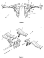
- Figure 1:
- Is a front view of an article carrier according to one embodiment of the present invention, with the carrier in a carriage position.
- Figure 2:
- Is an exploded view of the article carrier of
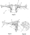
Figure 1 . - Figure 3:
- Is a transverse cross-section of the article carrier of
Figure 1 . - Figure 4:
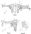
- is a partial side view of a sorting apparatus comprising a plurality of the article conveyors of
Figure 1 , conveying an item of produce. - Figure 5:
- Is a front view of the article carrier of
Figure 1 , with the releasable locking means in an unlocked position and the carriage portion in a lower weighing position. - Figure 6:
- Is a transverse cross-section of one side of the article carrier with the carriage portion in the lower weighing position.
- Figure 6A:
- Is an enlarged view of detail "A" of
Figure 6 . - Figure 7:
- Is a front view of the article carrier of
Figure 1 , with the releasable locking means in an unlocked position and the carriage portion in an upper weighing position. - Figure 8:
- Is a transverse cross-section of one side of the article carrier with the carriage portion in the upper weighing position.
- Figure 8A:
- Is an enlarged view of detail "B" of
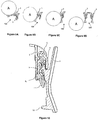
Figure 8 . - Figures 9a-9d:
- show a sequence of partial front views of the article carrier of
Figure 1 in use, discharging an article. - Figure 10:
- Is a transverse cross-section of one side of the article carrier, with the carriage portion in the discharge position.
- Referring first to
Figures 1 and 2 , an article carrier of the present invention is generally referenced byarrow 100. - The
article carrier 100 comprises amounting portion 1 for mounting thecarrier 100 to a conveyor chain (not shown), for example by means of aclip 2. - One or
more carrier portions 3 are mounted to the mountingportion 1. In the embodiment shown thecarrier 100 comprises fourcarrier portions 3, with twocarrier portions 3 on either side of the mountingportion 1. However, other embodiments (not shown) may have more or fewer carrier portions on either side of the mounting portion, or may have one or more carrier portions on only one side of the mounting portion. The article carrier is preferably substantially symmetrical about a central longitudinal plane, and about a vertical plane which is orthogonal to the longitudinal plane, so that the carrier can be mounted to the conveyor chain in either direction. - In the embodiment shown the
carrier portions 3 are provided as elongate "fingers", and define a cupped shape in order to securely hold an article. - Each
carrier portion 3 is connected to the mountingportion 1 by a connectingmember 4. The connectingmember 4 is rotatably connected to the mountingportion 1 such that it can rotate about a first axis of rotation R1. Thecarrier portion 3 is rotatably connected to the connectingmember 4 such that it can rotate relative to the connectingmember 4 about a second axis of rotation R2. The first and second axes of rotation R1, R2 are spaced apart, and in many embodiments are at opposite ends of the connectingmember 4. - The
article carrier 100 is further provided with a releasable carrier support means 5. In the embodiment shown the carrier support means 5 comprises an over-centre type linkage which has afirst portion 5a rotatably connected to the mountingportion 1 at or adjacent afirst end 6 and asecond portion 5b rotatably connected to the connectingmember 4 at asecond end 7. Thelinkage 5 is of a type which can transmit compressive forces when a link, preferably a hingedconnection 5c, between the first andsecond portions - In the embodiment shown the connection between the
second end 7 of theover-centre linkage 5 and the connectingmember 4 is collinear with the connection between the connectingmember 4 and thecarrier portion 3. However, this is not necessarily the case. The connection between thesecond end 7 of the over-centre linkage and the connectingmember 4 may be at any point on the connectingmember 4 which is not collinear with the connecting member's connection to the mountingportion 1. - In the embodiment shown in
Figure 1 , theover-centre linkage 5 is in a locked position, suitable for conveying an article on thecarrier portion 3. - In order to maintain the
carrier portion 3 in a substantially horizontal orientation (in use), suitable for conveying an article, the rotation of thecarrier portion 3 relative to the connectingmember 4 must be limited in order to avoid rotation of thecarrier portion 3 under its own weight (and the weight of the article). As is best seen inFigure 3 , in a preferred embodiment the carrier portion comprises arotation limiting formation 10 which extends to an opposite side of the second axis of rotation R2 from the side on which the centre of gravity C of the carrier portion is located. Therotation limiting portion 10 is shaped to bear against the connectingmember 4 in order to resist rotation of thecarrier portion 3 under the influence of gravity. In the embodiment shown thecarrier portion 3 is able to rotate in the opposite direction (i.e anticlockwise inFigure 3 ) about the second axis of rotation R2, although rotation in this direction is ultimately limited by interference between aninner edge 13 of the carrier portion (seeFigure 6 ) and the mountingportion 1. -
Figure 4 shows an article of produce P being conveyed by a sorting system of the present invention, with the article of produce being supported by a plurality ofarticle carriers 100. - Referring next to
Figures 5 and 6 , thearticle carrier 100 is particularly suited for use with sorting systems which individually weigh each item. By exerting a laterally outward force on atrigger portion 11 of the over-centre linkage (for example with a ramp or cam surface, or a solenoid operated trigger pushing mechanism), theover-centre linkage 5 can be moved from the locked position shown inFigure 1 over-centre to the unlocked position shown inFigures 5 and 6 , whereby theover-centre linkage 5 no longer supports the weight of the connectingmember 4,carrier portion 3 and any produce carried on thecarrier portion 3. - The
over-centre mechanism 5 is unlocked as thecarrier portion 3 moves over a weighing means W. Theunsupported carrier portion 3 bears on the weighing means W, and so the weighing means W is able to measure the weight of the item on the carrier portion 3 (and the carrier portion itself). In some embodiments the sorting apparatus may comprise a support surface (not shown) immediately before and/or after the weighing means in order to guide thecarrier portion 3 on and/or off the weighing means W. - In the embodiment shown the underside of the
carrier portion 3 is provided with a pair of spaced apart downwardly protruding bearing surfaces 12. These bearing surfaces 12 ensure that the contact between thecarrier portion 3 and the weighing means W occurs in a consistent and predictable place, and also helps to minimise the drag created by sliding thecarrier portion 3 over the surface of the weighing means W. - As can be seen in
Figures 5 and 6 , in the embodiment shown, the centre of thecarrier portion 3 maintains a substantially horizontal orientation during the weighing operation. -
Figures 5 and 6 show thecarrier portion 3 at the lowest position in which accurate weighing can occur. If thecarrier portion 3 were to be lowered any further relative to the mountingportion 1 then aninner edge 13 of thecarrier portion 3 would abut the mountingportion 1, thereby making accurate weighing impossible. -
Figures 7 and 8 show thecarrier portion 3 at the highest position in which weighing can occur. Further elevation (relative to the mounting portion 1) of thecarrier portion 3 beyond this position will result in theover-centre linkage 5 being placed in tension and/or therotation limiting portion 10 abutting the connectingmember 4. In one embodiment the centre of thecarrier portion 3 is approximately 6mm higher (relative to the mounting portion 1) when in the highest position (shown inFigures 7 and 8 ), relative to when it is in the lowest position (shown inFigures 5 and 6 ). Therotation limiting portion 10 does not abut or bear on the connecting member 4 (or any other member) when the carrier portion is in a weighing position. - Those skilled in the art will appreciate that because the first and second axes of rotation R1, R2 are substantially parallel to the direction of travel of the
carrier portion 3 as it moves over the weighing means W (and the direction of travel of the conveyor chain), the force exerted by the connectingmember 4 to move thecarrier portion 3 over the weighing means W has little or no vertical component, and so has a minimal effect on the accuracy of the weight measurement. To further minimise any vertical component of force exerted by the connecting member, the weighing means is preferably located such that the first and second axes of rotation R1, R2 are both horizontally orientated during the weighing operation. -
Figures 9a-9d illustrate an article of produce A being discharged from thearticle carrier 100 as a result of the releasable carrier support means 5 being unlocked and thearticle carrier 3 moving to a discharge position. - The releasable carrier support means 5 is unlocked when the
article carrier 100 is adjacent a selected receiving portion of the sorting apparatus. The releasable carrier support means 5 is preferably unlocked by a solenoid operated trigger pushing mechanism or similar apparatus (not shown), as has been described above. The particular receiving portion which the sorting apparatus elects to eject the produce into may depend on the weight of the produce, as well as information gathered from other assessment apparatus such as cameras and the like. - As can be seen in
Figures 9a-9d , the article A tends to fall substantially vertically, with thearticle carrier 100 exerting almost no horizontal force on the article A as it drops. Thecarrier portion 3 is able to rotate from a substantially horizontal orientation to a substantially vertical one. -
Figure 10 shows thecarrier portion 3 in the discharge position. - The sorting apparatus is preferably provided with a ramp or cam surface (not shown) immediately ahead a final receiving portion of the apparatus. The ramp acts on the trigger portion of any article carriers which have not yet been released into the discharge position. In this way it is assured that the produce is discharged from all of the
article carriers 100 before they begin a new cycle of the apparatus. - Unless the context clearly requires otherwise, throughout the description and the claims, the words "comprise", "comprising", and the like, are to be construed in an inclusive sense as opposed to an exclusive or exhaustive sense, that is to say, in the sense of "including, but not limited to".
- Where in the foregoing description, reference has been made to specific components or integers of the invention having known equivalents, then such equivalents are herein incorporated as if individually set forth.
- Although this invention has been described by way of example and with reference to possible embodiments thereof, it is to be understood that modifications or improvements may be made thereto without departing from the scope of the appended claims.
Claims (13)
- An article carrier (100) comprising:a mounting portion (1) adapted for connection to a conveyor,a connecting member (4) rotatably connected to the mounting portion (1) and rotatable relative to the mounting portion (1) about a first axis of rotation (R1) substantially parallel to a direction of travel of the article carrier (100) when in use,a carrier portion (3) rotatably connected to the connecting member (4) and rotatable relative to the connecting member (4) about a second axis of rotation (R2) substantially parallel to a direction of travel of the article carrier (100) when in use, wherein the first axis of rotation (R1) is spaced apart from the second axis of rotation (R2), anda releasably lockable carrier support means (5) adapted to support the carrier portion (3) in a carriage position when in a locked state, and to allow rotation of the carrier portion (3) to a discharge position when in an unlocked state,characterized in that, the carrier portion (3) further comprises a rotation limiting portion (10) adapted to limit rotation of the carrier portion (3) relative to the connecting member (4) when the releasably lockable carrier support means (5) is in the locked state in which the rotation limiting portion (10) bears on the connecting member (4).
- The article carrier of claim 1, wherein, when the releasably lockable carrier support means (5) is in the unlocked state, the carrier portion (3) is adapted to move to a weighing position in which the rotation limiting portion (10) does not bear on the connecting member (4).
- The article carrier of any one of claims 1 to 2, wherein the releasably lockable carrier support means (5) comprises an over-centre linkage.
- The article carrier of claim 3, wherein the over-centre linkage is rotatably connected to the mounting portion (1).
- The article carrier of claim 3 or 4, wherein the over-centre linkage is rotatably connected to the connecting member (1).
- The article carrier of claim 5, wherein the connection between the over-centre linkage and the connecting member (4) is co-linear with the second axis of rotation (R2).
- The article carrier of claim 3, wherein the over-centre linkage comprises a first portion (5a) which is connected to the mounting portion (1) and a second portion (5b) which is connected to the connecting member (4), wherein the first portion (5a) is rotatably connected to the second portion (5b).
- The article carrier of claim 7, wherein the first portion (5a) of the over-centre linkage comprises a trigger portion (11) for moving the over-centre linkage to an unlocked position.
- The article carrier of any one of the preceding claims, wherein the article carrier (100) is provided with a plurality carrier portions (3).
- The article carrier of any one of claims 1 to 9, wherein the article carrier (100) has at least one carrier portion (3) on each side of a central plane of the mounting portion.
- The article carrier of any one of claims 1 to 10 wherein the article carrier (100) has at least one plane of symmetry.
- The article carrier of claim 11, wherein the article carrier (100) has two planes of symmetry.
- A sorting apparatus comprising a plurality of article carriers (100) as claimed in any one of the preceding claims.
Priority Applications (1)
| Application Number | Priority Date | Filing Date | Title |
|---|---|---|---|
| PL13852682T PL2917138T3 (en) | 2012-11-08 | 2013-11-06 | Article carrier for a grading apparatus |
Applications Claiming Priority (2)
| Application Number | Priority Date | Filing Date | Title |
|---|---|---|---|
| NZ60348112 | 2012-11-08 | ||
| PCT/NZ2013/000199 WO2014073987A1 (en) | 2012-11-08 | 2013-11-06 | Article carrier for a grading apparatus |
Publications (3)
| Publication Number | Publication Date |
|---|---|
| EP2917138A1 EP2917138A1 (en) | 2015-09-16 |
| EP2917138A4 EP2917138A4 (en) | 2016-06-08 |
| EP2917138B1 true EP2917138B1 (en) | 2019-01-02 |
Family
ID=50684960
Family Applications (1)
| Application Number | Title | Priority Date | Filing Date |
|---|---|---|---|
| EP13852682.7A Active EP2917138B1 (en) | 2012-11-08 | 2013-11-06 | Article carrier for a grading apparatus |
Country Status (14)
| Country | Link |
|---|---|
| US (1) | US9527113B2 (en) |
| EP (1) | EP2917138B1 (en) |
| JP (1) | JP2015533649A (en) |
| KR (1) | KR20150110476A (en) |
| CN (1) | CN104981419B (en) |
| AU (1) | AU2013341875A1 (en) |
| BR (1) | BR112015010460A2 (en) |
| CL (1) | CL2015001216A1 (en) |
| DK (1) | DK2917138T3 (en) |
| ES (1) | ES2718206T3 (en) |
| MX (1) | MX357853B (en) |
| PL (1) | PL2917138T3 (en) |
| TR (1) | TR201904813T4 (en) |
| WO (1) | WO2014073987A1 (en) |
Families Citing this family (17)
| Publication number | Priority date | Publication date | Assignee | Title |
|---|---|---|---|---|
| CH710660A1 (en) * | 2015-01-29 | 2016-07-29 | Wrh Walter Reist Holding Ag | Delivery unit for a conveyor and conveyor with at least one such delivery unit. |
| FR3035087B1 (en) * | 2015-04-17 | 2017-04-21 | Maf Agrobotic | DEVICE FOR TRANSPORTING OBJECTS AND DEVICE FOR CONVEYING AND WEIGHING EQUIPPED WITH SUCH TRANSPORT DEVICES |
| ITUB20160534A1 (en) * | 2016-01-20 | 2017-07-20 | Unitec Spa | DISCREET TRANSPORT UNIT FOR BLUEBERRIES AND SIMILAR ORTHOPHYDRATE PRODUCTS |
| CN110023211B (en) * | 2016-07-01 | 2021-06-29 | 康派克科技有限公司 | Conveyor system and its article carrier |
| IT201700052580A1 (en) * | 2017-05-16 | 2018-11-16 | Unitec Spa | PLANT FOR TREATMENT OF FRUIT AND VEGETABLE PRODUCTS. |
| KR102577242B1 (en) | 2017-12-28 | 2023-09-11 | 주식회사 대웅제약 | Amino-methylpiperidine derivatives as kinase inhibitor |
| CN108325865B (en) * | 2018-03-12 | 2024-03-19 | 浙江大学 | Single-chain double-support fruit cup device for fruit and vegetable sorting |
| JP6935940B2 (en) * | 2018-07-19 | 2021-09-15 | 片山チエン株式会社 | Goods sorting device |
| CN109719041B (en) * | 2019-02-28 | 2024-08-09 | 广东力生智能有限公司 | Sorting machine trolley turning disc mechanism |
| CN109794418B (en) * | 2019-02-28 | 2024-09-20 | 广东力生智能有限公司 | Tray-turning type sorting machine |
| CN110293072B (en) * | 2019-07-12 | 2020-12-15 | 嘉兴华竹电子有限公司 | Marine product packing apparatus capable of automatically classifying according to weight |
| US11851218B1 (en) * | 2019-09-23 | 2023-12-26 | Amazon Technologies, Inc. | Material handling apparatus |
| WO2022083555A1 (en) * | 2020-10-19 | 2022-04-28 | 杭州托华机器人有限公司 | Sorting and pallet turning device, sorting system and sorting method |
| CN112275649B (en) * | 2020-10-19 | 2022-05-17 | 杭州托华机器人有限公司 | Bearing mechanism, sorting system and working method thereof |
| WO2022150742A1 (en) * | 2021-01-11 | 2022-07-14 | Durand-Wayland, Inc. | Produce sorting and weighing systems and methods |
| WO2023105505A1 (en) * | 2021-12-10 | 2023-06-15 | Kennedy Technologies Limited | Apparatus and methods relating to sorting objects |
| CN117918290B (en) * | 2024-01-24 | 2026-03-06 | 浙江省海洋水产研究所 | An automatic weighing and grading device for large yellow croaker |
Family Cites Families (18)
| Publication number | Priority date | Publication date | Assignee | Title |
|---|---|---|---|---|
| FR688897A (en) * | 1929-04-15 | 1930-08-29 | Burton Fils Sarl Ets | Selective transporter for various objects |
| WO1993007972A1 (en) | 1991-10-15 | 1993-04-29 | Colour Vision Systems Pty. Ltd. | Conveying system for foodstuffs |
| EP0808785B1 (en) | 1992-12-22 | 1999-09-22 | Horticultural Automation Limited | Article grading apparatus |
| US5677516A (en) | 1994-08-23 | 1997-10-14 | Durand-Wayland, Inc. | Article weighing and sorting apparatus with improved weigh cup |
| JP3358327B2 (en) * | 1994-10-26 | 2002-12-16 | 石川島播磨重工業株式会社 | Tray sorter defective tray detector |
| DE4447396C1 (en) * | 1994-12-23 | 1996-06-05 | Mannesmann Ag | Sorting conveyor with a tilting tray |
| US5611419A (en) | 1995-01-24 | 1997-03-18 | Sunkist Growers, Inc. | Monorail conveyor system |
| CH689786A5 (en) * | 1995-02-10 | 1999-11-15 | Grapha Holding Ag Patentwesen | Betaetigungsvorrichtung for tilting a component. |
| FR2730711B1 (en) | 1995-02-21 | 1997-05-09 | Materiel Arboriculture | DEVICE FOR SUPPLYING A SORTING UNIT OF LONGIFORM PRODUCTS, SUCH AS CARROTS, SORTING UNIT COMPRISING SAME, AND DISPENSING AND CALIBRATING DEVICE FOR THIS SORTING UNIT. |
| ES1043355Y (en) * | 1999-06-29 | 2000-05-01 | Morigi Romana Amaducci | IMPROVED CONVEYOR FOR FRUIT SELECTION. |
| JP5093708B2 (en) * | 2000-11-09 | 2012-12-12 | 株式会社横崎製作所 | Sorting material take-out device for sorting conveyor |
| CN2513958Y (en) * | 2001-09-03 | 2002-10-02 | 珠海方博工业有限公司 | Pull-down type tripping controllable car |
| AUPS319602A0 (en) * | 2002-06-26 | 2002-07-18 | Colour Vision Systems Pty Ltd | Fruit handling equipment |
| CN1867412B (en) * | 2003-10-09 | 2010-08-25 | Fps食品加工系统公司 | Brackets for sorting equipment |
| FR2924700A1 (en) | 2007-12-10 | 2009-06-12 | Materiel Arboriculture | Elongated product e.g. cucumber, conveying device for use as sorting and packaging unit, has orienting device rotating main direction of products so that products are oriented with main direction orthogonal to longitudinal direction |
| DE102008024586A1 (en) * | 2008-05-21 | 2009-11-26 | Beumer Maschinenfabrik Gmbh & Co. Kg | Sorting system with a vertical sorter |
| AU2010206498B2 (en) * | 2009-01-23 | 2014-04-17 | Maf Agrobotic | Fruit handling equipment |
| AU2011201654A1 (en) | 2010-03-22 | 2011-10-06 | Compac Technologies Limited | Article Carrier and Mechanisms Therefor |
-
2013
- 2013-11-06 US US14/441,623 patent/US9527113B2/en active Active
- 2013-11-06 TR TR2019/04813T patent/TR201904813T4/en unknown
- 2013-11-06 WO PCT/NZ2013/000199 patent/WO2014073987A1/en not_active Ceased
- 2013-11-06 CN CN201380057904.1A patent/CN104981419B/en not_active Expired - Fee Related
- 2013-11-06 JP JP2015541719A patent/JP2015533649A/en active Pending
- 2013-11-06 ES ES13852682T patent/ES2718206T3/en active Active
- 2013-11-06 DK DK13852682.7T patent/DK2917138T3/en active
- 2013-11-06 PL PL13852682T patent/PL2917138T3/en unknown
- 2013-11-06 AU AU2013341875A patent/AU2013341875A1/en not_active Abandoned
- 2013-11-06 BR BR112015010460A patent/BR112015010460A2/en not_active IP Right Cessation
- 2013-11-06 EP EP13852682.7A patent/EP2917138B1/en active Active
- 2013-11-06 KR KR1020157014874A patent/KR20150110476A/en not_active Ceased
- 2013-11-06 MX MX2015005709A patent/MX357853B/en active IP Right Grant
-
2015
- 2015-05-07 CL CL2015001216A patent/CL2015001216A1/en unknown
Non-Patent Citations (1)
| Title |
|---|
| None * |
Also Published As
| Publication number | Publication date |
|---|---|
| MX357853B (en) | 2018-07-26 |
| CL2015001216A1 (en) | 2015-09-25 |
| KR20150110476A (en) | 2015-10-02 |
| PL2917138T3 (en) | 2019-08-30 |
| TR201904813T4 (en) | 2019-04-22 |
| EP2917138A4 (en) | 2016-06-08 |
| DK2917138T3 (en) | 2019-04-15 |
| MX2015005709A (en) | 2016-06-30 |
| US20150298175A1 (en) | 2015-10-22 |
| BR112015010460A2 (en) | 2017-07-11 |
| CN104981419A (en) | 2015-10-14 |
| AU2013341875A1 (en) | 2015-05-07 |
| JP2015533649A (en) | 2015-11-26 |
| ES2718206T3 (en) | 2019-06-28 |
| WO2014073987A1 (en) | 2014-05-15 |
| EP2917138A1 (en) | 2015-09-16 |
| WO2014073987A8 (en) | 2015-05-28 |
| CN104981419B (en) | 2017-06-09 |
| US9527113B2 (en) | 2016-12-27 |
Similar Documents
| Publication | Publication Date | Title |
|---|---|---|
| US9527113B2 (en) | Article carrier for a grading apparatus | |
| NL2003516C2 (en) | TRANSPORTATION DEVICE FOR TRANSPORTING A PRODUCT, AND SORTING DEVICE AND METHOD FOR THIS. | |
| US4660665A (en) | Accurate weight sizing | |
| AU2015254679B2 (en) | Device for unilateral analysis of products by turning and automatic sorting and conveying device incorporating same | |
| EP3478607B1 (en) | Conveyor system and article carriers therefor | |
| WO2013131141A1 (en) | Fruit handling equipment | |
| WO2004002861A1 (en) | Fruit handling equipment | |
| US4413690A (en) | Weighing cup | |
| CN117999133A (en) | Fruit sorting equipment | |
| NL2003166C2 (en) | HOLDER, DEVICE AND METHOD FOR SORTING AND / OR TRANSPORTING PRODUCTS. | |
| US6003653A (en) | Article grading apparatus | |
| NZ617389B2 (en) | Article carrier for a grading apparatus | |
| WO2015167345A1 (en) | Article carrier and conveyor for sorting system | |
| ES2718175T3 (en) | Compounds of 1-oxo-1,2-dihydroisoquinolin-7-yl- (thiophen-2-yl-5-substituted) -sulfonamide, formulations containing these compounds, and their use as inhibitors of AICARFT in the treatment of cancers | |
| US20250042673A1 (en) | Apparatus and methods relating to sorting objects | |
| NL1034181C2 (en) | Device for transporting round objects. | |
| JPH01274884A (en) | Tilting mechanism of pan in fruit sorting machine or the like | |
| NZ726410B2 (en) | Device for unilateral analysis of products by turning and automatic sorting and conveying device incorporating same | |
| JP2004131284A (en) | Sorting device | |
| JP2006021068A (en) | Drop sorter | |
| PL226372B1 (en) | Transporting-transmitting carrier for products sorted into qualification devices of fruit or vegetables in the shape of a sphere or an ellipse | |
| JPH08252541A (en) | Grader for spherical vegetables and fruits, such as tomatoes | |
| JPH10129833A (en) | Agricultural sorting conveyor | |
| CN107660123A (en) | Convey transporter and conveying device, the operation method and pasta dryer of transporter or conveying device for the bar of strip wheaten food | |
| JP2011001112A (en) | Melon box-packing device |
Legal Events
| Date | Code | Title | Description |
|---|---|---|---|
| PUAI | Public reference made under article 153(3) epc to a published international application that has entered the european phase |
Free format text: ORIGINAL CODE: 0009012 |
|
| 17P | Request for examination filed |
Effective date: 20150417 |
|
| AK | Designated contracting states |
Kind code of ref document: A1 Designated state(s): AL AT BE BG CH CY CZ DE DK EE ES FI FR GB GR HR HU IE IS IT LI LT LU LV MC MK MT NL NO PL PT RO RS SE SI SK SM TR |
|
| AX | Request for extension of the european patent |
Extension state: BA ME |
|
| DAX | Request for extension of the european patent (deleted) | ||
| REG | Reference to a national code |
Ref country code: DE Ref legal event code: R079 Ref document number: 602013049358 Country of ref document: DE Free format text: PREVIOUS MAIN CLASS: B65G0047340000 Ipc: B07B0013080000 |
|
| RA4 | Supplementary search report drawn up and despatched (corrected) |
Effective date: 20160506 |
|
| RIC1 | Information provided on ipc code assigned before grant |
Ipc: B65G 47/96 20060101ALI20160429BHEP Ipc: B07C 5/36 20060101ALI20160429BHEP Ipc: B07B 13/08 20060101AFI20160429BHEP |
|
| GRAP | Despatch of communication of intention to grant a patent |
Free format text: ORIGINAL CODE: EPIDOSNIGR1 |
|
| STAA | Information on the status of an ep patent application or granted ep patent |
Free format text: STATUS: GRANT OF PATENT IS INTENDED |
|
| INTG | Intention to grant announced |
Effective date: 20180711 |
|
| GRAS | Grant fee paid |
Free format text: ORIGINAL CODE: EPIDOSNIGR3 |
|
| GRAA | (expected) grant |
Free format text: ORIGINAL CODE: 0009210 |
|
| STAA | Information on the status of an ep patent application or granted ep patent |
Free format text: STATUS: THE PATENT HAS BEEN GRANTED |
|
| AK | Designated contracting states |
Kind code of ref document: B1 Designated state(s): AL AT BE BG CH CY CZ DE DK EE ES FI FR GB GR HR HU IE IS IT LI LT LU LV MC MK MT NL NO PL PT RO RS SE SI SK SM TR |
|
| REG | Reference to a national code |
Ref country code: GB Ref legal event code: FG4D |
|
| REG | Reference to a national code |
Ref country code: CH Ref legal event code: EP Ref country code: AT Ref legal event code: REF Ref document number: 1083703 Country of ref document: AT Kind code of ref document: T Effective date: 20190115 |
|
| REG | Reference to a national code |
Ref country code: IE Ref legal event code: FG4D |
|
| REG | Reference to a national code |
Ref country code: DE Ref legal event code: R096 Ref document number: 602013049358 Country of ref document: DE |
|
| REG | Reference to a national code |
Ref country code: DK Ref legal event code: T3 Effective date: 20190408 |
|
| RAP2 | Party data changed (patent owner data changed or rights of a patent transferred) |
Owner name: COMPAC TECHNOLOGIES LIMITED |
|
| REG | Reference to a national code |
Ref country code: LT Ref legal event code: MG4D |
|
| REG | Reference to a national code |
Ref country code: NL Ref legal event code: MP Effective date: 20190102 |
|
| REG | Reference to a national code |
Ref country code: NL Ref legal event code: FP |
|
| REG | Reference to a national code |
Ref country code: AT Ref legal event code: MK05 Ref document number: 1083703 Country of ref document: AT Kind code of ref document: T Effective date: 20190102 |
|
| REG | Reference to a national code |
Ref country code: ES Ref legal event code: FG2A Ref document number: 2718206 Country of ref document: ES Kind code of ref document: T3 Effective date: 20190628 |
|
| PG25 | Lapsed in a contracting state [announced via postgrant information from national office to epo] |
Ref country code: LT Free format text: LAPSE BECAUSE OF FAILURE TO SUBMIT A TRANSLATION OF THE DESCRIPTION OR TO PAY THE FEE WITHIN THE PRESCRIBED TIME-LIMIT Effective date: 20190102 Ref country code: FI Free format text: LAPSE BECAUSE OF FAILURE TO SUBMIT A TRANSLATION OF THE DESCRIPTION OR TO PAY THE FEE WITHIN THE PRESCRIBED TIME-LIMIT Effective date: 20190102 Ref country code: PT Free format text: LAPSE BECAUSE OF FAILURE TO SUBMIT A TRANSLATION OF THE DESCRIPTION OR TO PAY THE FEE WITHIN THE PRESCRIBED TIME-LIMIT Effective date: 20190502 Ref country code: SE Free format text: LAPSE BECAUSE OF FAILURE TO SUBMIT A TRANSLATION OF THE DESCRIPTION OR TO PAY THE FEE WITHIN THE PRESCRIBED TIME-LIMIT Effective date: 20190102 Ref country code: NO Free format text: LAPSE BECAUSE OF FAILURE TO SUBMIT A TRANSLATION OF THE DESCRIPTION OR TO PAY THE FEE WITHIN THE PRESCRIBED TIME-LIMIT Effective date: 20190402 |
|
| PG25 | Lapsed in a contracting state [announced via postgrant information from national office to epo] |
Ref country code: LV Free format text: LAPSE BECAUSE OF FAILURE TO SUBMIT A TRANSLATION OF THE DESCRIPTION OR TO PAY THE FEE WITHIN THE PRESCRIBED TIME-LIMIT Effective date: 20190102 Ref country code: GR Free format text: LAPSE BECAUSE OF FAILURE TO SUBMIT A TRANSLATION OF THE DESCRIPTION OR TO PAY THE FEE WITHIN THE PRESCRIBED TIME-LIMIT Effective date: 20190403 Ref country code: IS Free format text: LAPSE BECAUSE OF FAILURE TO SUBMIT A TRANSLATION OF THE DESCRIPTION OR TO PAY THE FEE WITHIN THE PRESCRIBED TIME-LIMIT Effective date: 20190502 Ref country code: HR Free format text: LAPSE BECAUSE OF FAILURE TO SUBMIT A TRANSLATION OF THE DESCRIPTION OR TO PAY THE FEE WITHIN THE PRESCRIBED TIME-LIMIT Effective date: 20190102 Ref country code: RS Free format text: LAPSE BECAUSE OF FAILURE TO SUBMIT A TRANSLATION OF THE DESCRIPTION OR TO PAY THE FEE WITHIN THE PRESCRIBED TIME-LIMIT Effective date: 20190102 Ref country code: BG Free format text: LAPSE BECAUSE OF FAILURE TO SUBMIT A TRANSLATION OF THE DESCRIPTION OR TO PAY THE FEE WITHIN THE PRESCRIBED TIME-LIMIT Effective date: 20190402 |
|
| REG | Reference to a national code |
Ref country code: DE Ref legal event code: R097 Ref document number: 602013049358 Country of ref document: DE |
|
| PG25 | Lapsed in a contracting state [announced via postgrant information from national office to epo] |
Ref country code: AL Free format text: LAPSE BECAUSE OF FAILURE TO SUBMIT A TRANSLATION OF THE DESCRIPTION OR TO PAY THE FEE WITHIN THE PRESCRIBED TIME-LIMIT Effective date: 20190102 Ref country code: CZ Free format text: LAPSE BECAUSE OF FAILURE TO SUBMIT A TRANSLATION OF THE DESCRIPTION OR TO PAY THE FEE WITHIN THE PRESCRIBED TIME-LIMIT Effective date: 20190102 Ref country code: RO Free format text: LAPSE BECAUSE OF FAILURE TO SUBMIT A TRANSLATION OF THE DESCRIPTION OR TO PAY THE FEE WITHIN THE PRESCRIBED TIME-LIMIT Effective date: 20190102 Ref country code: EE Free format text: LAPSE BECAUSE OF FAILURE TO SUBMIT A TRANSLATION OF THE DESCRIPTION OR TO PAY THE FEE WITHIN THE PRESCRIBED TIME-LIMIT Effective date: 20190102 Ref country code: SK Free format text: LAPSE BECAUSE OF FAILURE TO SUBMIT A TRANSLATION OF THE DESCRIPTION OR TO PAY THE FEE WITHIN THE PRESCRIBED TIME-LIMIT Effective date: 20190102 Ref country code: AT Free format text: LAPSE BECAUSE OF FAILURE TO SUBMIT A TRANSLATION OF THE DESCRIPTION OR TO PAY THE FEE WITHIN THE PRESCRIBED TIME-LIMIT Effective date: 20190102 |
|
| PLBE | No opposition filed within time limit |
Free format text: ORIGINAL CODE: 0009261 |
|
| STAA | Information on the status of an ep patent application or granted ep patent |
Free format text: STATUS: NO OPPOSITION FILED WITHIN TIME LIMIT |
|
| PG25 | Lapsed in a contracting state [announced via postgrant information from national office to epo] |
Ref country code: SM Free format text: LAPSE BECAUSE OF FAILURE TO SUBMIT A TRANSLATION OF THE DESCRIPTION OR TO PAY THE FEE WITHIN THE PRESCRIBED TIME-LIMIT Effective date: 20190102 |
|
| 26N | No opposition filed |
Effective date: 20191003 |
|
| PG25 | Lapsed in a contracting state [announced via postgrant information from national office to epo] |
Ref country code: SI Free format text: LAPSE BECAUSE OF FAILURE TO SUBMIT A TRANSLATION OF THE DESCRIPTION OR TO PAY THE FEE WITHIN THE PRESCRIBED TIME-LIMIT Effective date: 20190102 |
|
| REG | Reference to a national code |
Ref country code: CH Ref legal event code: PL |
|
| PG25 | Lapsed in a contracting state [announced via postgrant information from national office to epo] |
Ref country code: CH Free format text: LAPSE BECAUSE OF NON-PAYMENT OF DUE FEES Effective date: 20191130 Ref country code: LI Free format text: LAPSE BECAUSE OF NON-PAYMENT OF DUE FEES Effective date: 20191130 Ref country code: MC Free format text: LAPSE BECAUSE OF FAILURE TO SUBMIT A TRANSLATION OF THE DESCRIPTION OR TO PAY THE FEE WITHIN THE PRESCRIBED TIME-LIMIT Effective date: 20190102 Ref country code: LU Free format text: LAPSE BECAUSE OF NON-PAYMENT OF DUE FEES Effective date: 20191106 |
|
| PGFP | Annual fee paid to national office [announced via postgrant information from national office to epo] |
Ref country code: TR Payment date: 20201028 Year of fee payment: 8 Ref country code: NL Payment date: 20201127 Year of fee payment: 8 |
|
| PGFP | Annual fee paid to national office [announced via postgrant information from national office to epo] |
Ref country code: GB Payment date: 20201123 Year of fee payment: 8 Ref country code: DE Payment date: 20201120 Year of fee payment: 8 Ref country code: DK Payment date: 20201124 Year of fee payment: 8 Ref country code: IT Payment date: 20201124 Year of fee payment: 8 Ref country code: FR Payment date: 20201119 Year of fee payment: 8 Ref country code: ES Payment date: 20201202 Year of fee payment: 8 |
|
| PGFP | Annual fee paid to national office [announced via postgrant information from national office to epo] |
Ref country code: PL Payment date: 20201027 Year of fee payment: 8 Ref country code: BE Payment date: 20201127 Year of fee payment: 8 |
|
| PGFP | Annual fee paid to national office [announced via postgrant information from national office to epo] |
Ref country code: IE Payment date: 20210330 Year of fee payment: 8 |
|
| PG25 | Lapsed in a contracting state [announced via postgrant information from national office to epo] |
Ref country code: CY Free format text: LAPSE BECAUSE OF FAILURE TO SUBMIT A TRANSLATION OF THE DESCRIPTION OR TO PAY THE FEE WITHIN THE PRESCRIBED TIME-LIMIT Effective date: 20190102 |
|
| PG25 | Lapsed in a contracting state [announced via postgrant information from national office to epo] |
Ref country code: MT Free format text: LAPSE BECAUSE OF FAILURE TO SUBMIT A TRANSLATION OF THE DESCRIPTION OR TO PAY THE FEE WITHIN THE PRESCRIBED TIME-LIMIT Effective date: 20190102 Ref country code: HU Free format text: LAPSE BECAUSE OF FAILURE TO SUBMIT A TRANSLATION OF THE DESCRIPTION OR TO PAY THE FEE WITHIN THE PRESCRIBED TIME-LIMIT; INVALID AB INITIO Effective date: 20131106 |
|
| REG | Reference to a national code |
Ref country code: DE Ref legal event code: R119 Ref document number: 602013049358 Country of ref document: DE |
|
| REG | Reference to a national code |
Ref country code: DK Ref legal event code: EBP Effective date: 20211130 |
|
| PG25 | Lapsed in a contracting state [announced via postgrant information from national office to epo] |
Ref country code: MK Free format text: LAPSE BECAUSE OF FAILURE TO SUBMIT A TRANSLATION OF THE DESCRIPTION OR TO PAY THE FEE WITHIN THE PRESCRIBED TIME-LIMIT Effective date: 20190102 |
|
| REG | Reference to a national code |
Ref country code: NL Ref legal event code: MM Effective date: 20211201 |
|
| GBPC | Gb: european patent ceased through non-payment of renewal fee |
Effective date: 20211106 |
|
| PG25 | Lapsed in a contracting state [announced via postgrant information from national office to epo] |
Ref country code: BE Free format text: LAPSE BECAUSE OF NON-PAYMENT OF DUE FEES Effective date: 20211130 |
|
| REG | Reference to a national code |
Ref country code: BE Ref legal event code: MM Effective date: 20211130 |
|
| PG25 | Lapsed in a contracting state [announced via postgrant information from national office to epo] |
Ref country code: NL Free format text: LAPSE BECAUSE OF NON-PAYMENT OF DUE FEES Effective date: 20211201 |
|
| PG25 | Lapsed in a contracting state [announced via postgrant information from national office to epo] |
Ref country code: IE Free format text: LAPSE BECAUSE OF NON-PAYMENT OF DUE FEES Effective date: 20211106 Ref country code: GB Free format text: LAPSE BECAUSE OF NON-PAYMENT OF DUE FEES Effective date: 20211106 Ref country code: DK Free format text: LAPSE BECAUSE OF NON-PAYMENT OF DUE FEES Effective date: 20211130 Ref country code: DE Free format text: LAPSE BECAUSE OF NON-PAYMENT OF DUE FEES Effective date: 20220601 |
|
| PG25 | Lapsed in a contracting state [announced via postgrant information from national office to epo] |
Ref country code: FR Free format text: LAPSE BECAUSE OF NON-PAYMENT OF DUE FEES Effective date: 20211130 |
|
| PG25 | Lapsed in a contracting state [announced via postgrant information from national office to epo] |
Ref country code: IT Free format text: LAPSE BECAUSE OF NON-PAYMENT OF DUE FEES Effective date: 20211106 |
|
| REG | Reference to a national code |
Ref country code: ES Ref legal event code: FD2A Effective date: 20230221 |
|
| PG25 | Lapsed in a contracting state [announced via postgrant information from national office to epo] |
Ref country code: ES Free format text: LAPSE BECAUSE OF NON-PAYMENT OF DUE FEES Effective date: 20211107 |
|
| PG25 | Lapsed in a contracting state [announced via postgrant information from national office to epo] |
Ref country code: PL Free format text: LAPSE BECAUSE OF NON-PAYMENT OF DUE FEES Effective date: 20211106 |