EP2916781B1 - Medical device delivery system - Google Patents
Medical device delivery system Download PDFInfo
- Publication number
- EP2916781B1 EP2916781B1 EP13798783.0A EP13798783A EP2916781B1 EP 2916781 B1 EP2916781 B1 EP 2916781B1 EP 13798783 A EP13798783 A EP 13798783A EP 2916781 B1 EP2916781 B1 EP 2916781B1
- Authority
- EP
- European Patent Office
- Prior art keywords
- retainer
- medical device
- delivery system
- delivery
- relative movement
- Prior art date
- Legal status (The legal status is an assumption and is not a legal conclusion. Google has not performed a legal analysis and makes no representation as to the accuracy of the status listed.)
- Active
Links
Images




Classifications
-
- A—HUMAN NECESSITIES
- A61—MEDICAL OR VETERINARY SCIENCE; HYGIENE
- A61F—FILTERS IMPLANTABLE INTO BLOOD VESSELS; PROSTHESES; DEVICES PROVIDING PATENCY TO, OR PREVENTING COLLAPSING OF, TUBULAR STRUCTURES OF THE BODY, e.g. STENTS; ORTHOPAEDIC, NURSING OR CONTRACEPTIVE DEVICES; FOMENTATION; TREATMENT OR PROTECTION OF EYES OR EARS; BANDAGES, DRESSINGS OR ABSORBENT PADS; FIRST-AID KITS
- A61F2/00—Filters implantable into blood vessels; Prostheses, i.e. artificial substitutes or replacements for parts of the body; Appliances for connecting them with the body; Devices providing patency to, or preventing collapsing of, tubular structures of the body, e.g. stents
- A61F2/02—Prostheses implantable into the body
- A61F2/24—Heart valves ; Vascular valves, e.g. venous valves; Heart implants, e.g. passive devices for improving the function of the native valve or the heart muscle; Transmyocardial revascularisation [TMR] devices; Valves implantable in the body
- A61F2/2427—Devices for manipulating or deploying heart valves during implantation
-
- A—HUMAN NECESSITIES
- A61—MEDICAL OR VETERINARY SCIENCE; HYGIENE
- A61F—FILTERS IMPLANTABLE INTO BLOOD VESSELS; PROSTHESES; DEVICES PROVIDING PATENCY TO, OR PREVENTING COLLAPSING OF, TUBULAR STRUCTURES OF THE BODY, e.g. STENTS; ORTHOPAEDIC, NURSING OR CONTRACEPTIVE DEVICES; FOMENTATION; TREATMENT OR PROTECTION OF EYES OR EARS; BANDAGES, DRESSINGS OR ABSORBENT PADS; FIRST-AID KITS
- A61F2/00—Filters implantable into blood vessels; Prostheses, i.e. artificial substitutes or replacements for parts of the body; Appliances for connecting them with the body; Devices providing patency to, or preventing collapsing of, tubular structures of the body, e.g. stents
- A61F2/02—Prostheses implantable into the body
- A61F2/24—Heart valves ; Vascular valves, e.g. venous valves; Heart implants, e.g. passive devices for improving the function of the native valve or the heart muscle; Transmyocardial revascularisation [TMR] devices; Valves implantable in the body
- A61F2/2427—Devices for manipulating or deploying heart valves during implantation
- A61F2/243—Deployment by mechanical expansion
- A61F2/2433—Deployment by mechanical expansion using balloon catheter
-
- A—HUMAN NECESSITIES
- A61—MEDICAL OR VETERINARY SCIENCE; HYGIENE
- A61F—FILTERS IMPLANTABLE INTO BLOOD VESSELS; PROSTHESES; DEVICES PROVIDING PATENCY TO, OR PREVENTING COLLAPSING OF, TUBULAR STRUCTURES OF THE BODY, e.g. STENTS; ORTHOPAEDIC, NURSING OR CONTRACEPTIVE DEVICES; FOMENTATION; TREATMENT OR PROTECTION OF EYES OR EARS; BANDAGES, DRESSINGS OR ABSORBENT PADS; FIRST-AID KITS
- A61F2/00—Filters implantable into blood vessels; Prostheses, i.e. artificial substitutes or replacements for parts of the body; Appliances for connecting them with the body; Devices providing patency to, or preventing collapsing of, tubular structures of the body, e.g. stents
- A61F2/02—Prostheses implantable into the body
- A61F2/24—Heart valves ; Vascular valves, e.g. venous valves; Heart implants, e.g. passive devices for improving the function of the native valve or the heart muscle; Transmyocardial revascularisation [TMR] devices; Valves implantable in the body
- A61F2/2427—Devices for manipulating or deploying heart valves during implantation
- A61F2/2436—Deployment by retracting a sheath
-
- A—HUMAN NECESSITIES
- A61—MEDICAL OR VETERINARY SCIENCE; HYGIENE
- A61F—FILTERS IMPLANTABLE INTO BLOOD VESSELS; PROSTHESES; DEVICES PROVIDING PATENCY TO, OR PREVENTING COLLAPSING OF, TUBULAR STRUCTURES OF THE BODY, e.g. STENTS; ORTHOPAEDIC, NURSING OR CONTRACEPTIVE DEVICES; FOMENTATION; TREATMENT OR PROTECTION OF EYES OR EARS; BANDAGES, DRESSINGS OR ABSORBENT PADS; FIRST-AID KITS
- A61F2/00—Filters implantable into blood vessels; Prostheses, i.e. artificial substitutes or replacements for parts of the body; Appliances for connecting them with the body; Devices providing patency to, or preventing collapsing of, tubular structures of the body, e.g. stents
- A61F2/95—Instruments specially adapted for placement or removal of stents or stent-grafts
-
- A—HUMAN NECESSITIES
- A61—MEDICAL OR VETERINARY SCIENCE; HYGIENE
- A61F—FILTERS IMPLANTABLE INTO BLOOD VESSELS; PROSTHESES; DEVICES PROVIDING PATENCY TO, OR PREVENTING COLLAPSING OF, TUBULAR STRUCTURES OF THE BODY, e.g. STENTS; ORTHOPAEDIC, NURSING OR CONTRACEPTIVE DEVICES; FOMENTATION; TREATMENT OR PROTECTION OF EYES OR EARS; BANDAGES, DRESSINGS OR ABSORBENT PADS; FIRST-AID KITS
- A61F2/00—Filters implantable into blood vessels; Prostheses, i.e. artificial substitutes or replacements for parts of the body; Appliances for connecting them with the body; Devices providing patency to, or preventing collapsing of, tubular structures of the body, e.g. stents
- A61F2/02—Prostheses implantable into the body
- A61F2/24—Heart valves ; Vascular valves, e.g. venous valves; Heart implants, e.g. passive devices for improving the function of the native valve or the heart muscle; Transmyocardial revascularisation [TMR] devices; Valves implantable in the body
- A61F2/2412—Heart valves ; Vascular valves, e.g. venous valves; Heart implants, e.g. passive devices for improving the function of the native valve or the heart muscle; Transmyocardial revascularisation [TMR] devices; Valves implantable in the body with soft flexible valve members, e.g. tissue valves shaped like natural valves
- A61F2/2418—Scaffolds therefor, e.g. support stents
-
- A—HUMAN NECESSITIES
- A61—MEDICAL OR VETERINARY SCIENCE; HYGIENE
- A61F—FILTERS IMPLANTABLE INTO BLOOD VESSELS; PROSTHESES; DEVICES PROVIDING PATENCY TO, OR PREVENTING COLLAPSING OF, TUBULAR STRUCTURES OF THE BODY, e.g. STENTS; ORTHOPAEDIC, NURSING OR CONTRACEPTIVE DEVICES; FOMENTATION; TREATMENT OR PROTECTION OF EYES OR EARS; BANDAGES, DRESSINGS OR ABSORBENT PADS; FIRST-AID KITS
- A61F2/00—Filters implantable into blood vessels; Prostheses, i.e. artificial substitutes or replacements for parts of the body; Appliances for connecting them with the body; Devices providing patency to, or preventing collapsing of, tubular structures of the body, e.g. stents
- A61F2/95—Instruments specially adapted for placement or removal of stents or stent-grafts
- A61F2002/9505—Instruments specially adapted for placement or removal of stents or stent-grafts having retaining means other than an outer sleeve, e.g. male-female connector between stent and instrument
-
- A—HUMAN NECESSITIES
- A61—MEDICAL OR VETERINARY SCIENCE; HYGIENE
- A61F—FILTERS IMPLANTABLE INTO BLOOD VESSELS; PROSTHESES; DEVICES PROVIDING PATENCY TO, OR PREVENTING COLLAPSING OF, TUBULAR STRUCTURES OF THE BODY, e.g. STENTS; ORTHOPAEDIC, NURSING OR CONTRACEPTIVE DEVICES; FOMENTATION; TREATMENT OR PROTECTION OF EYES OR EARS; BANDAGES, DRESSINGS OR ABSORBENT PADS; FIRST-AID KITS
- A61F2/00—Filters implantable into blood vessels; Prostheses, i.e. artificial substitutes or replacements for parts of the body; Appliances for connecting them with the body; Devices providing patency to, or preventing collapsing of, tubular structures of the body, e.g. stents
- A61F2/95—Instruments specially adapted for placement or removal of stents or stent-grafts
- A61F2002/9534—Instruments specially adapted for placement or removal of stents or stent-grafts for repositioning of stents
-
- A—HUMAN NECESSITIES
- A61—MEDICAL OR VETERINARY SCIENCE; HYGIENE
- A61F—FILTERS IMPLANTABLE INTO BLOOD VESSELS; PROSTHESES; DEVICES PROVIDING PATENCY TO, OR PREVENTING COLLAPSING OF, TUBULAR STRUCTURES OF THE BODY, e.g. STENTS; ORTHOPAEDIC, NURSING OR CONTRACEPTIVE DEVICES; FOMENTATION; TREATMENT OR PROTECTION OF EYES OR EARS; BANDAGES, DRESSINGS OR ABSORBENT PADS; FIRST-AID KITS
- A61F2/00—Filters implantable into blood vessels; Prostheses, i.e. artificial substitutes or replacements for parts of the body; Appliances for connecting them with the body; Devices providing patency to, or preventing collapsing of, tubular structures of the body, e.g. stents
- A61F2/95—Instruments specially adapted for placement or removal of stents or stent-grafts
- A61F2/958—Inflatable balloons for placing stents or stent-grafts
- A61F2002/9583—Means for holding the stent on the balloon, e.g. using protrusions, adhesives or an outer sleeve
-
- A—HUMAN NECESSITIES
- A61—MEDICAL OR VETERINARY SCIENCE; HYGIENE
- A61F—FILTERS IMPLANTABLE INTO BLOOD VESSELS; PROSTHESES; DEVICES PROVIDING PATENCY TO, OR PREVENTING COLLAPSING OF, TUBULAR STRUCTURES OF THE BODY, e.g. STENTS; ORTHOPAEDIC, NURSING OR CONTRACEPTIVE DEVICES; FOMENTATION; TREATMENT OR PROTECTION OF EYES OR EARS; BANDAGES, DRESSINGS OR ABSORBENT PADS; FIRST-AID KITS
- A61F2/00—Filters implantable into blood vessels; Prostheses, i.e. artificial substitutes or replacements for parts of the body; Appliances for connecting them with the body; Devices providing patency to, or preventing collapsing of, tubular structures of the body, e.g. stents
- A61F2/95—Instruments specially adapted for placement or removal of stents or stent-grafts
- A61F2/962—Instruments specially adapted for placement or removal of stents or stent-grafts having an outer sleeve
- A61F2/966—Instruments specially adapted for placement or removal of stents or stent-grafts having an outer sleeve with relative longitudinal movement between outer sleeve and prosthesis, e.g. using a push rod
- A61F2002/9665—Instruments specially adapted for placement or removal of stents or stent-grafts having an outer sleeve with relative longitudinal movement between outer sleeve and prosthesis, e.g. using a push rod with additional retaining means
-
- A—HUMAN NECESSITIES
- A61—MEDICAL OR VETERINARY SCIENCE; HYGIENE
- A61F—FILTERS IMPLANTABLE INTO BLOOD VESSELS; PROSTHESES; DEVICES PROVIDING PATENCY TO, OR PREVENTING COLLAPSING OF, TUBULAR STRUCTURES OF THE BODY, e.g. STENTS; ORTHOPAEDIC, NURSING OR CONTRACEPTIVE DEVICES; FOMENTATION; TREATMENT OR PROTECTION OF EYES OR EARS; BANDAGES, DRESSINGS OR ABSORBENT PADS; FIRST-AID KITS
- A61F2230/00—Geometry of prostheses classified in groups A61F2/00 - A61F2/26 or A61F2/82 or A61F9/00 or A61F11/00 or subgroups thereof
- A61F2230/0063—Three-dimensional shapes
- A61F2230/0095—Saddle-shaped
-
- A—HUMAN NECESSITIES
- A61—MEDICAL OR VETERINARY SCIENCE; HYGIENE
- A61F—FILTERS IMPLANTABLE INTO BLOOD VESSELS; PROSTHESES; DEVICES PROVIDING PATENCY TO, OR PREVENTING COLLAPSING OF, TUBULAR STRUCTURES OF THE BODY, e.g. STENTS; ORTHOPAEDIC, NURSING OR CONTRACEPTIVE DEVICES; FOMENTATION; TREATMENT OR PROTECTION OF EYES OR EARS; BANDAGES, DRESSINGS OR ABSORBENT PADS; FIRST-AID KITS
- A61F2230/00—Geometry of prostheses classified in groups A61F2/00 - A61F2/26 or A61F2/82 or A61F9/00 or A61F11/00 or subgroups thereof
- A61F2230/0063—Three-dimensional shapes
- A61F2230/0097—Harpoon-shaped
-
- A—HUMAN NECESSITIES
- A61—MEDICAL OR VETERINARY SCIENCE; HYGIENE
- A61F—FILTERS IMPLANTABLE INTO BLOOD VESSELS; PROSTHESES; DEVICES PROVIDING PATENCY TO, OR PREVENTING COLLAPSING OF, TUBULAR STRUCTURES OF THE BODY, e.g. STENTS; ORTHOPAEDIC, NURSING OR CONTRACEPTIVE DEVICES; FOMENTATION; TREATMENT OR PROTECTION OF EYES OR EARS; BANDAGES, DRESSINGS OR ABSORBENT PADS; FIRST-AID KITS
- A61F2250/00—Special features of prostheses classified in groups A61F2/00 - A61F2/26 or A61F2/82 or A61F9/00 or A61F11/00 or subgroups thereof
- A61F2250/0003—Special features of prostheses classified in groups A61F2/00 - A61F2/26 or A61F2/82 or A61F9/00 or A61F11/00 or subgroups thereof having an inflatable pocket filled with fluid, e.g. liquid or gas
Definitions
- Certain embodiments of the present invention are related to medical device delivery systems.
- Medical devices can be delivered to a site within a patient through a variety of techniques.
- a medical device can be implanted or otherwise delivered through conventional open surgical techniques, such as for example open-heart surgery.
- the medical device can be implanted or delivered percutaneously.
- a medical device such as a valve prosthesis can be compacted and loaded onto a delivery device for advancement through a patient's vasculature in a transfemoral, transapical, or transatrial procedure.
- a medical device delivery system includes a catheter and a retainer disposed within the catheter and engageable with the medical device to restrain relative movement of the medical device in a first axial direction.
- the retainer includes a curved surface configured to disengage the medical device from the retainer when there is a predetermined amount of relative movement between the medical device and the retainer in a second axial direction.
- medical device delivery system includes an inflatable balloon configured to facilitate disengagement of the medical
- WO 2012/032187 A1 relates to valve replacement devices, a delivery device for a valve replacement and a method for production of a valve replacement device.
- EP 2 111 828 A2 relates to a stent attachment and deployment mechanism.
- WO 2013/154678 A1 relates to a stent-graft delivery system having a rotatable single shaft tip capture mechanism.
- US 2011/0257720 A1 relates to a controlled tip release stent graft delivery system and method.
- US 2007/0088420 A1 relates to stent development systems and methods.
- US 2004/0220585 A1 relates to implant delivery technologies. device from the retainer by providing a radially outward force on a portion of the medical device when the balloon is inflated.
- a medical device delivery system includes a catheter having a lumen, a shaft having a lumen and disposed within the catheter lumen, and a retainer disposed within the shaft lumen and engaged with the medical device to restrain relative movement of the medical device in an axial direction.
- the shaft can include a protrusion extending from an inside surface of the shaft lumen that is configured to disengage the medical device from the retainer when the retainer engages the protrusion.
- a medical device delivery system includes a catheter, a retainer disposed within the catheter and engaged with the medical device to restrain relative movement of the medical device in an axial direction, and an actuator configured to radially retract the retainer and disengage the medical device from the retainer.
- a medical device delivery system includes a catheter, a base disposed within a lumen of the catheter and engaged with the medical device to restrain relative movement of the medical device in an axial direction, and a sheath covering the base and engaged with a portion of the medical device to restrain relative movement of the medical device in a radial direction.
- a medical device delivery system includes a catheter, a base disposed within a lumen of the catheter and engaged with the medical device to restrain relative movement of the medical device in an axial direction, and a pin disposed within the base and engaged with the medical device to restrain relative movement of the medical device in a radial direction. The pin can retract to disengage the medical device from the base.
- a medical device delivery system includes a catheter, a first retainer disposed within the catheter and engaged with the medical device to restrain relative movement of the medical device in an axial direction, and a second retainer disposed within the catheter and engaged with the medical device to restrain relative movement of the medical device in an outward radial direction.
- the second retainer is configured such that relative movement in an axial direction between the second retainer and the medical device allows the medical device to disengage from the retainer.
- a medical device delivery system includes a catheter and a retainer configured to restrain a medical device in an axial direction.
- the medical device can include a coupling portion configured to engage with the retainer.
- the coupling portion can have a curved surface that facilitates disengagement of the medical device from the retainer.
- FIG. 1A-1S illustrate front views of medical devices 10 and 12.
- Medical devices 10 and 12 are shown in the form of prosthetic heart valves including frames 14 and 16 with valve bodies 18 and 20 attached thereto.
- Medical device 10 includes coupling portions 22 in the form of eyelets 24. Other suitable types of coupling portions, such as those shown for example in FIG. 13 can be used.
- Coupling portions 22 can extend from frame 14 or can be attached or otherwise connected to frame 14.
- Coupling portions 22 can be formed and/or reinforced for engagement with one or more of the retainer systems, retainers, or delivery catheters described herein.
- Coupling portions 22 are shown disposed on a distal end of frame 14. As used herein, the terms “distal” or “outflow” are understood to mean downstream to the direction of blood flow.
- coupling portions 22 can be disposed on a proximal end of frame 14, in a longitudinal center of frame 14, or in any other desired location on or in a medical device, such as medical device 10. In some embodiments, coupling portions 22 can be located on both a distal end and a proximal end of medical device 10. In some embodiments, coupling portions 22 can extend from a coupling piece attached to frame 14. In some embodiments, the medical device does not include eyelets 24. One embodiment of such a medical device is shown for example in FIG. 1B . Medical device 12 includes openings 26, formed by one or more wires 28 of frame 16 which can serve as coupling portions. For example, in some embodiments, one or more of the retainer systems can be attached directly or indirectly to openings 26 instead of eyelets.
- Suitable medical devices are not limited to prosthetic heart valves.
- the medical device can be a device configured to be transported via a delivery catheter.
- the medical device can be an expandable device, such as, for example, a percutaneously delivered device configured to be compacted and loaded onto a delivery catheter for advancement through a patient's vasculature.
- the device can also be a nonimplantable device.
- the device can be an embolic filter that is not designed to be implanted within the patient's body.
- the device can be a tool that can be used, for example, to retrieve an item from inside a patient.
- FIGs. 2A-2B respectively illustrate a front perspective view of a portion of a delivery catheter 30 including a retainer 32 and a cross-sectional view of retainer 32 in accordance with an embodiment.
- Delivery catheter 30 can include a sheath 34, with retainer 32 disposed within a lumen 36 of sheath 34, and a shaft 38 connected to retainer 32.
- retainer 32 can be configured to both retain and controllably release a medical device.
- Retainer 32 can have a body 40 including a lumen 42 configured to receive shaft 38.
- Retainer 32 can have a recessed portion 44 extending around an entire perimeter of retainer 32 or only a portion thereof.
- body 40 can be substantially cylindrical or any other suitable shape.
- Retainer 32 can includes one or more extensions 46 extending over recessed portion 44.
- extensions 46 can be in the form of a hook.
- two extensions 46 can be disposed about 180 degrees apart along the radial periphery of retainer 32.
- retainer 32 includes only a single extension 46.
- retainer 32 includes more than two extensions that are uniformly or nonuniformly disposed along the radial periphery of retainer 32.
- separate recessed portions 44 are formed for each extension 46 of retainer 32.
- the configuration of recessed portion 44 and extensions 46 can allow retainer 32 to secure a portion of a medical device between recessed portion 44 and extensions 46 to restrain radially outward movement thereof.
- the retainer 32 includes a curved surface 48 that can be configured to force at least a portion of the medical device to radially expand and disengage from the retainer when the medical device is moved in an axial direction against curved surface 48.
- retainer 32 is configured to restrain movement of the medical device in single axial direction, such as for example axial direction 50.
- retainer 32 can be spring-loaded.
- one or more of the retainers or retainer systems described herein, such as retainer 32 can retain and controllably release the medical device without requiring modification to the medical device.
- extensions 46 can be configured to attach to the medical device itself without requiring distinct coupling portions, such as eyelets.
- extensions 46 can be configured to extension directly into the frame via openings in the frame, such as openings 26 of frame 16 shown and described with respect to FIG. 1B .
- a valve prosthesis including a frame with eyelets is first compressed for delivered via delivery catheter 30.
- Retainer 32 is connected to the eyelets via extensions 46.
- Retainer 32 is pulled into delivery catheter 30 along with the medical device.
- delivery catheter 30 can be advanced in a retrograde manner through the patient's femoral artery and into the patient's descending aorta. It is understood that the femoral approach is only exemplary and that other delivery routes, such as a radial approach or another approach, can be employed.
- valve prosthesis is then deployed within a body lumen of the patient's aortic valve.
- Described herein is an example of an expanded valve prosthesis within a body lumen of a patient.
- Retainer 32 can release valve prosthesis by moving in axial direction 56 relative to the frame in a range from about 1 mm to about 2 mm. This can force a portion of the valve prosthesis against curved surface 48 of retainer 32 to unextension eyelets of valve prosthesis from retainer 32.
- Valve prosthesis is then free to expand against body lumen.
- the valve prosthesis can expand against an annulus within body lumen.
- retainer 32 is disengaged from valve prosthesis after valve prosthesis expands against annulus Once valve prosthesis is disengaged from retainer 32, retainer 32 can be pulled back into delivery catheter 30.
- Retainer system includes retainer attached to a shaft.
- a spring can be disposed around or within shaft.
- retainer system can be configured to both retain and controllably release a medical device.
- retainer system can release a medical device by movement of retainer in axial distal direction.
- retainer system can use spring to spring-load retainer.
- a spring-loaded retainer system can be configured to facilitate movement of retainer in any desired direction.
- FIGs. 5A and 5B illustrate views of a retainer system 72 in accordance with an embodiment.
- FIG. 5A illustrates retainer system 72 and delivery catheter 74 connected to a medical device 76 within a body lumen 78 of a patient.
- Delivery catheter 74 can include a tip 80 attached to a shaft 82.
- retainer system 72 can be configured to both retain and controllably release a medical device.
- retainer system 72 can include a retainer 84 that can be configured to restrain medical device 76 in one or both axial directions 86.
- Retainer system 72 can include an inflatable balloon 88 disposed immediately distal to retainer 84 and within a portion of medical device 76.
- Balloon 88 can be configured to force at least a portion of medical device 76 to radially expand and disengage from retainer 84 when balloon 88 is inflated.
- FIG. 58 illustrates a view of retainer system 72 after balloon 88 has been inflated.
- balloon 88 need only be partially inflated.
- balloon 88 must be fully inflated.
- balloon 88 is configured to contact a wall of body lumen 78 when balloon 88 is expanded.
- balloon 88 is substantially the same size as retainer 84 when inflated.
- One or more features of retainer 84, retainer system 72, balloon 88, and/or delivery catheter 74 can be used or adapted for use with any of the other retainers, retainer systems, and/or delivery catheters described herein.
- FIGs. 6A-C illustrate retainer 90 in accordance with an embodiment.
- FIG. 6A shows a front-perspective view of retainer 90.
- FIG. 6B shows a partially cross-sectional view of retainer 90 in a first state.
- FIG. 6C shows a partially cross-sectional view of retainer 90 in a second state.
- retainer 90 can be configured to both retain and controllably release a medical device.
- retainer 90 can release a medical device by moving in one or both axial directions, such as axial direction 92.
- Retainer 90 includes a base 94 having one or more protrusions 96 configured to restrain a corresponding portion of a medical device. Stepped surfaces 98 and 100 of protrusion 96 are configured to engage with a coupling portion of the medical device, such as eyelets (not shown), in order to restrain movement of the medical device in one or both axial directions.
- Retainer 90 includes one or more actuators 102 configured to engage with a shaft 104 via corresponding protrusion 106 formed on an inside surface 108 thereof.
- actuators 102 can be in the form of toggles that bump a medical device off retainer 90.
- one or more actuators 102 include a hinge 110 which can allow actuator 102 to rotate relative to hinge 110 so that when a first end 112 of actuator 102 extending outward from base 94 is retracted inward, a second end 114 of actuator 102 is moved outward.
- actuator 102 includes an angled surface 116 configured to engage with a corresponding angled surface 118 of protrusion 106 within shaft 104.
- One or both of angled surfaces 116 and 118 can be configured to translate axial movement of first end 112 into radial movement, which can allow actuator 102 to rotate around hinge 110.
- FIGs. 6A and 6B show actuator 102 before it is rotated, with first end 112 extending outward from base 94, whereas FIG. 6C shows actuator 102 after it is rotated, with second end 114 extending outward from base 94.
- Actuator 102 can have any suitable shape.
- retainer 90 can includes two substantially U-shaped actuators 102 which rotate independently from each other.
- One or more features of retainer 90 can be used or adapted for use with any of the other retainers, retainer systems, and/or delivery catheters described herein.
- FIGs. 7A-C illustrate retainer 120 in accordance with an embodiment.
- FIGs. 7A and 7B respectively illustrate a front-perspective view and a side view of retainer 120 attached to eyelets 122 of a medical device.
- FIG. 7C shows a side view of retainer 120 rotated in a counter-clockwise direction relative to FIG. 7B and detached from eyelets 122.
- retainer 120 can be configured to both retain and controllably release a medical device.
- Retainer 120 includes one or more protrusions 124 extending from base 126.
- Protrusions 124 can be configured to restrain a corresponding portion of a medical device, such as eyelets 122.
- Stepped surface 128 of protrusion 124 is configured to engage with a coupling portion of the medical device, such as eyelets 122, in order to restrain movement of the medical device in one or both axial directions.
- Retainer 120 can release eyelets 122 by moving in a rotational direction 130 or other rotational direction.
- protrusions 124 can include a surface, such as angled surface 132, which can facilitate removal of the medical device as retainer 120 is rotated.
- retainer 120 can include multiple angled or curved surfaces, or a combination thereof.
- retainer 120 can includes a stepped surface 134 on one side of retainer 120 which does not facilitate release of eyelets 122 when retainer 120 is rotated against stepped surface 134.
- both surfaces 132 and 134 of retainer 120 are angled so that rotation of retainer 120 in either direction can facilitate release of eyelets 122.
- FIG. 7D illustrates a cross-sectional view of a shaft 136 that can be used with retainer 120.
- Shaft 136 includes one or more protrusions 138 located on an inside surface of a lumen 140 of shaft 136.
- one or more protrusions 124 of retainer 120 are configured to engage with one or more protrusions 138 of shaft 136 to facilitate detaching eyelets from retainer 120.
- protrusions 124 can be configured to "knock" or "bump” off eyelets 122 as retainer 120 is rotated.
- shaft 136 is configured to be rotated while retainer 120 does not rotate.
- protrusions 138 of shaft 136 can "knock” or “bump” off the medical device from protrusions 124 of retainer 120.
- shaft 136 can include an angled surface 142 which can translate axial movement of shaft 136 into rotational movement of shaft 136.
- shaft 136 can include an angled surface 142 on an inside surface of lumen 140, that can engage with a surface (not shown) within the delivery system to force rotation of shaft 136 as shaft 136 is moved in axial direction 144.
- angled surface 142 can be located on an outside surface of shaft 136.
- Shaft 136 can be configured such that it can move a predetermined axial distance before engaging with the surface that forces rotation of shaft 136.
- retainer 120 can be rotated about 90 degrees before disengaging from the medical device.
- One or more features of retainer 120 and/or shaft 136 can be used or adapted for use with any of the other retainers, retainer systems, shafts, and/or delivery catheters described herein.
- FIGs. 8A-B illustrate a shaft system 145 in accordance with an embodiment.
- shaft system 145 can translate axial movement of a shaft into rotational movement of the shaft.
- shaft system 145 can be included in one or more of the retainer systems described herein or in another suitable retainer system.
- shaft system 145 can serve to allow one or more protrusions to "knock" or "bump" off a medical device from a retainer.
- FIG. 8A illustrates a partially sectional view of shaft system 145 and FIG. 8B illustrates a view of shaft system 145 along line 8-8 of FIG. 8A .
- Shaft system 145 can include an inner shaft 147 disposed within an outer shaft 149.
- a protrusion 151 can be fixed to inner shaft 147.
- a guide 153 can be slidably disposed on inner shaft 147.
- Guide 153 can includes an angled surface 155 configured to rotate protrusion 151 (which in some configurations can thereby rotate inner shaft 147) as protrusion 151 is moved in axial direction 157 against angled surface 155.
- guide 153 includes a gap 159 which can allow protrusion 151 to slide within gap 159 once a desired rotation has been achieved.
- gap 159 can extend along an entire length of guide 153. In some embodiments, gap 159 extends only along a portion of the length of guide 153.
- FIG. 9 and 10A-C illustrate a retainer system 146 and a portion of a medical device 148.
- FIG. 9 illustrates a front-perspective view of retainer system 146 engaged with eyelets 150 of medical device 148.
- FIGs. 10A-C illustrate various cross-sectional views of retainer system 146.
- retainer system 146 can be configured to both retain and controllably release a portion of a medical device.
- Retainer system 146 can include base 152, actuator 154, and sheath 158.
- Retainer system 146 can include one or more retainers 156.
- One or more retainers 156 are connected to base 152 via a hinge 160 about which retainers 156 can rotate.
- Retainers 156 can be configured to release eyelets 150 by being retracted into base 152.
- Retainers 156 include a first end 162 on a proximal end of retainer 156 and a second end 164 on a distal end of retainer 156.
- Second end 164 includes a protrusion 166 which engages with a portion of medical device 148, such as eyelet 150. Stepped surfaces 168 and 170 of protrusion 166 are configured to engage with eyelets 150, in order to restrain movement of medical device 148 in one or both axial directions.
- Actuator 154 includes a rounded protrusion 172 configured to engage with retainer 156 such that when rounded protrusion 172 is moved in distal axial direction 174, protrusion 166 engages with first end 162 of retainer 156. Force from this engagement can cause first end 162 to move radially outward, which can rotate retainer 156 relative to hinge 160 to radially retract second end 164. Retraction of protrusion 166 on second end 164 allows eyelet 150 to disengage from retainer 156.
- sheath 158 can initially cover base 152, retainer 156, actuator 154, and eyelets 150.
- sheath 158 is retracted in axial direction 174 to expose eyelets 150.
- actuator 154 is moved in axial direction 174, as protrusion 166 is pushed against first end 162, first end 162 is rotated radially outward, which forces second end 164 (as well as protrusion 166 on second end 164) to retract.
- eyelet 150 disengages from retainer 156 and is substantially free to move in one or both axial directions relative to retainer system 146.
- retainer 156 and/or retainer system 146 can be used or adapted for use with any of the other retainers, retainer systems, and/or delivery catheters described herein.
- FIGs. 11A-C illustrate retainer system 176 with a portion of a medical device 178.
- retainer system 176 can be configured to both retain and controllably release a medical device, such as a coupling portion 180 of medical device 178.
- Retainer system 176 can include a retainer 182 disposed within a lumen of an inner sheath 184.
- Inner sheath 184 itself can be disposed within a lumen of an outer sheath 186.
- outer sheath 186 can cover the entirety of the remaining pieces of retainer system 176 (or one or more portions thereof) and/or the entirety of medical device 178 (or a portion thereof).
- Retainer 182 can be substantially cylindrical in shape with a reduced diameter portion 188, an enlarged diameter portion 190 and a stepped surface 192 separating the two portions.
- One or both of the reduced diameter portion 188 and enlarged diameter portion 190 can extend around an entire peripheral surface of retainer 182. In some embodiments, one or both of the reduced diameter portion 188 and enlarged diameter portion 190 do not extend around the entire peripheral surface of retainer 182.
- a recess 194 can be formed within both enlarged diameter portion 190 and reduced diameter portion 188. Recess 194 can be configured to receive a portion of medical device 178.
- Recess 194 includes stepped surfaces 196, which can be configured to engage with corresponding stepped surface 200 on coupling portion 180 in order to restrain movement of medical device 178 in an axial direction.
- Stepped surface 202 of coupling portion can engage with corresponding stepped surface 192 of enlarged diameter portion 190 in order to restrain movement of medical device 178 in an axial direction.
- an operator can first retract outer sheath 186 in axial direction 204, which, as shown in FIG. 11B , can expose a portion of medical device 178 as well as retainer 182.
- the operator can then retract inner sheath 184 which, as shown in FIG. 11C , can fully expose medical device 178, including coupling portion 180.
- This can allow for medical device 178 to expand and disengage from retainer system 176.
- inner sheath 184 and outer sheath 186 can be retracted at the same time.
- inner sheath 184 can be retracted before outer sheath 186 is retracted.
- One or more features of retainer 182 and/or retainer system 176 can be used or adapted for use with any of the other retainers, retainer systems, and/or delivery catheters described herein.
- FIGs. 12A-C illustrate a retainer system 206 and a portion of a medical device 208.
- retainer system 206 can be configured to both retain and controllably release a portion of a medical device, such as medical device 208.
- Retainer system 206 can include a base 210, one or more pins 212 configured to retract into base 210, and a sheath 214.
- sheath 214 can cover the entirety of the other pieces of retainer system 206 (or one or more portions thereof) and/or the entirety of medical device 208 (or a portion thereof).
- Stepped surfaces 216 and 218 of base 210 are configured to engage with corresponding stepped surfaces 220 and 222 on coupling portion 224 of medical device 208 and can restrain movement of medical device 208 in one or both axial directions.
- an operator can first retract sheath 214 which, as shown in FIG. 12B , can fully expose coupling portion 224 of medical device 208. The operator can then retract pins 212 from coupling portion 224. This can allow for medical device 208 to expand and disengage from retainer system 206.
- sheath 214 and pins 212 can be retracted at the same time.
- pins 212 can be retracted before sheath 214 is retracted.
- retainer system 206 can be used or adapted for use with any of the other retainers, retainer systems, and/or delivery catheters described herein.
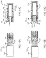
- FIGs. 13A-D illustrate a retainer system 226 and a portion of a medical device 228.
- FIGs. 13A-B respectively illustrate front views of retainer system 226 in a closed state and an open state.
- FIGs. 13C-D respectively illustrate cross-sectional views of retainer system 226 in a closed state and an open state.
- Retainer system 226 as shown in FIGs. 13C-D is rotated 90 degrees about its axis relative to retainer system 226 as shown in FIGs. 13A-B .
- retainer system 226 can be configured to both retain and controllably release a portion of a medical device, such as medical device 228.
- Retainer system 226 can include a base 230 and a cap 232 configured to cover a portion of medical device 228, such as eyelets 233.
- cap 232 can cover the entirety of the other parts of retainer system 226 (or one or more portions thereof) and/or the entirety of medical device 228 (or a portion thereof). For example, as shown in FIGs. 13A and 13C , when in a fully closed state, cap 232 can cover only a portion of eyelets 233.
- Stepped surfaces 235 and 237 of a protrusion 246 formed on base 230 are configured to engage with eyelet 233 in order to restrain movement of medical device 228 in one or both axial directions.
- Retainer system 226 can include a spring 240 that spring-loads cap 232, which in some embodiments can facilitate more reliable movement of cap 232 and more reliable disengagement of medical device 228 from retainer system 226.
- base 230 includes extensions 234 which extend into a cavity 236 formed in cap 232. Extensions 234 can include a protrusion 239 having a stepped surface 238 configured to engage with a corresponding stepped surface 243 of cap 232. In some embodiments, such as the embodiment shown in FIG.
- cap 232 can include an aperture 241 formed therein.
- aperture 241 can serve as an air vent for cap 232.
- an inside surface 242 of cap 232 can abut an end 244 of extensions 234 when retainer system 226 is in a closed state. In some embodiments, such a configuration can restrain movement of cap 232 in an axial direction.
- an operator can actuate cap 232 to retract it from covering eyelets 233. As shown in FIGs. 13B and 13D , this retraction can fully expose eyelets 233, which can allow medical device 228 to expand and disengage from retainer system 226.
- retainer system 226 can be used or adapted for use with any of the other retainers, retainer systems, and/or delivery catheters described herein.
- FIG. 14 illustrates a medical device 248 that can be used with one or more retainer systems described herein.
- Medical device 248 can include a frame 250 with one or more arms 252 extending therefrom.
- one or more of the arms 252 can include coupling portions 254 having a curved surface 256 on a first side and a stepped surface 258 on a second side.
- a stepped surface of the retainer system can be configured to engage with stepped surface 258 on coupling portion 254 in order to restrain movement of medical device 248 in one or both axial directions.
- curved surface 256 can facilitate disengagement of medical device 248 from a retainer system in one or more ways.
- curved surface 256 can reduce torque and/or friction generated between medical device 248 and a portion of a retainer system.
- curved surface 256 can be configured to re-direct axial force of coupling portion 254 into outward radial force to facilitate disengagement from the retainer system.
- One or more features of medical device 248 can be used or adapted for use with any of the other retainers, retainer systems, and/or delivery catheters described herein.
- FIGs. 15A-B illustrate medical device 248 within a portion of a delivery catheter 260 in accordance with an embodiment.
- FIG. 15A illustrates a partially transparent front view of delivery catheter 260.
- FIG 15B illustrates a cross-sectional view of delivery catheter 260.
- Delivery catheter 260 can include a medical device 248 and a tip 262 connected via a shaft 264 to a retainer system 266.
- Retainer system 266 can include a retainer 268, and a sheath 270 (shown in FIG. 15A ).
- sheath 270 can cover the entirety of the other pieces of retainer system 266 (or one or more portions thereof) and/or the entirety of medical device 248 (or a portion thereof).
- Stepped surface 272 of retainer 268 is configured to engage with corresponding stepped surface 258 on coupling portion 254 of medical device 248 in order to restrain movement of medical device 248 in one or both axial directions.
- Curved surface 274 of retainer 268 is configured to engage with corresponding curved surface 256 of coupling portion 254, which can facilitate disengagement of medical device 248 from retainer system 266.
- retainer 268, retainer system 266, and/or delivery catheter 260 can be used or adapted for use with any of other retainers, retainer systems, and/or delivery catheters described herein.
- FIGs. 16A-C illustrate medical device 248 within a portion of a delivery catheter 278 in accordance with an embodiment.
- Delivery catheter 278 can include medical device 248 and a tip 280 connected via a shaft 282 to a retainer system 284.
- Retainer system 284 can include a retainer 286, and a sheath 288.
- FIG. 16A illustrates a partially transparent front view of a portion of delivery catheter 278.
- FIG. 16B illustrates a cross-sectional view of a portion of delivery catheter 278 with sheath 288 covering retainer system 284.
- FIG. 16C illustrates a cross-sectional view of a portion of delivery catheter 278 with sheath 288 retracted to expose coupling portion 254 of medical device 248.
- Retainer system 284 can include a retainer 286 and a sheath 288.
- sheath 288 can cover the entirety of the other pieces of retainer system 284 (or one or more portions thereof) and/or the entirety of medical device 248 (or a portion thereof).
- Stepped surface 290 of retainer 286 is configured to engage with corresponding stepped surface 258 on coupling portion 254 of medical device 248 in order to restrain movement of medical device 248 in one or both axial directions.
- Curved surface 292 of retainer 286 is configured to engage with corresponding curved surface 256 of coupling portion 254, which can facilitate disengagement of medical device 248 from retainer system 284.
- One or more features of retainer 286, retainer system 284, and/or delivery catheter 278 can be used or adapted for use with any of other retainers, retainer systems, and/or delivery catheters described herein.
- one more of the parts can be made from suitable plastics, such as a suitable thermoplastic, suitable metals, and/or other suitable materials.
Landscapes
- Health & Medical Sciences (AREA)
- Cardiology (AREA)
- Engineering & Computer Science (AREA)
- Biomedical Technology (AREA)
- Vascular Medicine (AREA)
- Transplantation (AREA)
- Oral & Maxillofacial Surgery (AREA)
- Heart & Thoracic Surgery (AREA)
- Life Sciences & Earth Sciences (AREA)
- Animal Behavior & Ethology (AREA)
- General Health & Medical Sciences (AREA)
- Public Health (AREA)
- Veterinary Medicine (AREA)
- Mechanical Engineering (AREA)
- Media Introduction/Drainage Providing Device (AREA)
- Surgical Instruments (AREA)
Description
- Certain embodiments of the present invention are related to medical device delivery systems.
- Medical devices can be delivered to a site within a patient through a variety of techniques. For example, a medical device can be implanted or otherwise delivered through conventional open surgical techniques, such as for example open-heart surgery. In some embodiments, the medical device can be implanted or delivered percutaneously. For example, in some percutaneous techniques, a medical device, such as a valve prosthesis can be compacted and loaded onto a delivery device for advancement through a patient's vasculature in a transfemoral, transapical, or transatrial procedure. There is a continuous need for improved delivery systems for use in such surgical, percutaneous, and other delivery techniques. <insert new page 1a>
- The invention is defined in claim 1. Accordingly, , a medical device delivery system includes a catheter and a retainer disposed within the catheter and engageable with the medical device to restrain relative movement of the medical device in a first axial direction. The retainer includes a curved surface configured to disengage the medical device from the retainer when there is a predetermined amount of relative movement between the medical device and the retainer in a second axial direction. Further, the
- medical device delivery system includes an inflatable balloon configured to facilitate disengagement of the medical
- For example,
WO 2012/032187 A1 relates to valve replacement devices, a delivery device for a valve replacement and a method for production of a valve replacement device. -
EP 2 111 828 A2 -
WO 2013/154678 A1 relates to a stent-graft delivery system having a rotatable single shaft tip capture mechanism. -
US 2011/0257720 A1 relates to a controlled tip release stent graft delivery system and method. -
US 2007/0088420 A1 relates to stent development systems and methods. -
US 2004/0220585 A1 relates to implant delivery technologies. device from the retainer by providing a radially outward force on a portion of the medical device when the balloon is inflated. - In some embodiments, a medical device delivery system includes a catheter having a lumen, a shaft having a lumen and disposed within the catheter lumen, and a retainer disposed within the shaft lumen and engaged with the medical device to restrain relative movement of the medical device in an axial direction. The shaft can include a protrusion extending from an inside surface of the shaft lumen that is configured to disengage the medical device from the retainer when the retainer engages the protrusion.
- In some embodiments, a medical device delivery system includes a catheter, a retainer disposed within the catheter and engaged with the medical device to restrain relative movement of the medical device in an axial direction, and an actuator configured to radially retract the retainer and disengage the medical device from the retainer.
- In some embodiments, a medical device delivery system includes a catheter, a base disposed within a lumen of the catheter and engaged with the medical device to restrain relative movement of the medical device in an axial direction, and a sheath covering the base and engaged with a portion of the medical device to restrain relative movement of the medical device in a radial direction.
- In some embodiments, a medical device delivery system includes a catheter, a base disposed within a lumen of the catheter and engaged with the medical device to restrain relative movement of the medical device in an axial direction, and a pin disposed within the base and engaged with the medical device to restrain relative movement of the medical device in a radial direction. The pin can retract to disengage the medical device from the base.
- In some embodiments, a medical device delivery system includes a catheter, a first retainer disposed within the catheter and engaged with the medical device to restrain relative movement of the medical device in an axial direction, and a second retainer disposed within the catheter and engaged with the medical device to restrain relative movement of the medical device in an outward radial direction. The second retainer is configured such that relative movement in an axial direction between the second retainer and the medical device allows the medical device to disengage from the retainer.
- In some embodiments, a medical device delivery system includes a catheter and a retainer configured to restrain a medical device in an axial direction. The medical device can include a coupling portion configured to engage with the retainer. The coupling portion can have a curved surface that facilitates disengagement of the medical device from the retainer.
- The accompanying figures, which are incorporated herein, form part of the specification and illustrate embodiments of a valve prosthesis frame and delivery system. Together with the description, the figures further serve to explain the principles of and to enable a person skilled in the relevant art(s) to make, use, and implant the valve prosthesis described herein.
-
FIG. 1A illustrates a front view of a medical device for use with one or more of the medical device delivery systems described herein. -
FIG. 1B illustrates a front view of a medical device for use with one or more of the medical device delivery systems described herein. -
FIG. 2A illustrates a front-perspective view of a portion of a delivery catheter in accordance with an embodiment. -
FIG. 2B illustrates a cross-sectional view of a retainer of the delivery catheter ofFIG. 2A . -
FIG. 5A illustrates a view of a retainer system in accordance with an embodiment at a first stage in a delivery operation. -
FIG. 5B illustrates a view of the retainer system ofFIG. 5A at a second stage in a delivery operation. -
FIG. 6A illustrates a front-perspective view of a retainer in accordance with an embodiment at a first stage in a delivery operation. -
FIG. 6B illustrates a front view of the retainer ofFIG. 6A at a first stage in a delivery operation. -
FIG. 6C illustrates a front view of the retainer ofFIG. 6A at a second stage in a delivery operation. -
FIG. 7A illustrates a front-perspective view of a retainer in accordance with an embodiment at a first stage in a delivery operation. -
FIG. 7B illustrates a side view of the retainer ofFIG. 7A at a first stage in a delivery operation. -
FIG. 7C illustrates a side view of the retainer ofFIG. 7A at a second stage in a delivery operation. -
FIG. 7D illustrates a front view of a shaft for use with the retainer ofFIG. 7A . -
FIG. 8A illustrates a partially sectional view of a shaft system in accordance with an embodiment. -
FIG. 8B illustrates a view of the shaft system ofFIG. 8A along line 8-8 ofFIG. 8A . - FIG. 9 illustrates a front-perspective view of a retainer system in accordance with an embodiment along with a portion of a medical device.
-
FIG. 10A illustrates a cross-sectional view of the retainer system of FIG. 9 at a first stage in a delivery operation. -
FIG. 10B illustrates a cross-sectional view of the retainer system of FIG. 9 at a second stage in a delivery operation. -
FIG. 10C illustrates a cross-sectional view of the retainer system of FIG. 9 at a third stage in a delivery operation. -
FIG. 11A illustrates a front perspective view of a retainer system in accordance with an embodiment along with a portion of a medical device at a first stage in a delivery operation. -
FIG. 11B illustrates a front perspective view of the retainer system ofFIG. 11A at a second stage in a delivery operation. -
FIG. 11C illustrates a front perspective view of the retainer system ofFIG. 11A at a third stage in a delivery operation. -
FIG. 12A illustrates a front perspective view of a retainer system in accordance with an embodiment along with a portion of a medical device at a first stage in a delivery operation. -
FIG. 12B illustrates a front perspective view of the retainer system ofFIG. 12A at a second stage in a delivery operation. -
FIG. 12C illustrates a front perspective view of the retainer system ofFIG. 12A at a third stage in a delivery operation. -
FIG. 13A illustrates a front view of a retainer system in accordance with an embodiment along with a portion of a medical device at a first stage in a delivery operation. -
FIG. 13B illustrates a front view of the retainer system ofFIG. 13A at a second stage in a delivery operation. -
FIG. 13C illustrates a cross-sectional view of the retainer system ofFIG. 13A at a first stage. -
FIG. 13D illustrates a cross-sectional view of the retainer system ofFIG. 13A at a second stage in a delivery operation. - FIG. 14 illustrates a medical device for use with one or more of the medical device delivery systems described herein.
-
FIG. 15A illustrates a front view of a delivery catheter in accordance with an embodiment. -
FIG. 15B illustrates a cross-sectional view of the delivery catheter ofFIG. 15B . -
FIG. 16A illustrates a front view of a delivery catheter in accordance with an embodiment. -
FIG. 16B illustrates a cross-sectional view of the delivery catheter ofFIG. 16A at a first stage in a delivery operation. -
FIG. 16C illustrates a cross-sectional view of a portion of the delivery catheter ofFIG. 16A at a second stage in a delivery operation. - The following detailed description refers to the accompanying figures which illustrate several embodiments. Other embodiments are possible. . Therefore, the following detailed description is not meant to be limiting.
-
FIG. 1A-1S illustrate front views ofmedical devices Medical devices valves including frames valve bodies Medical device 10 includescoupling portions 22 in the form ofeyelets 24. Other suitable types of coupling portions, such as those shown for example inFIG. 13 can be used. Couplingportions 22 can extend fromframe 14 or can be attached or otherwise connected to frame 14. Couplingportions 22 can be formed and/or reinforced for engagement with one or more of the retainer systems, retainers, or delivery catheters described herein. Couplingportions 22 are shown disposed on a distal end offrame 14. As used herein, the terms "distal" or "outflow" are understood to mean downstream to the direction of blood flow. The terms "proximal" or "inflow" are understood to mean upstream to the direction of blood flow. In some embodiments,coupling portions 22 can be disposed on a proximal end offrame 14, in a longitudinal center offrame 14, or in any other desired location on or in a medical device, such asmedical device 10. In some embodiments,coupling portions 22 can be located on both a distal end and a proximal end ofmedical device 10. In some embodiments,coupling portions 22 can extend from a coupling piece attached to frame 14. In some embodiments, the medical device does not include eyelets 24. One embodiment of such a medical device is shown for example inFIG. 1B .Medical device 12 includesopenings 26, formed by one ormore wires 28 offrame 16 which can serve as coupling portions. For example, in some embodiments, one or more of the retainer systems can be attached directly or indirectly toopenings 26 instead of eyelets. - Suitable medical devices are not limited to prosthetic heart valves. For example, in some embodiments, the medical device can be a device configured to be transported via a delivery catheter. In some embodiments, the medical device can be an expandable device, such as, for example, a percutaneously delivered device configured to be compacted and loaded onto a delivery catheter for advancement through a patient's vasculature. The device can also be a nonimplantable device. For example, in some embodiments, the device can be an embolic filter that is not designed to be implanted within the patient's body. In some embodiments, the device can be a tool that can be used, for example, to retrieve an item from inside a patient.
-
FIGs. 2A-2B respectively illustrate a front perspective view of a portion of adelivery catheter 30 including aretainer 32 and a cross-sectional view ofretainer 32 in accordance with an embodiment.Delivery catheter 30 can include asheath 34, withretainer 32 disposed within alumen 36 ofsheath 34, and ashaft 38 connected toretainer 32. in some embodiments,retainer 32 can be configured to both retain and controllably release a medical device.Retainer 32 can have abody 40 including alumen 42 configured to receiveshaft 38.Retainer 32 can have a recessedportion 44 extending around an entire perimeter ofretainer 32 or only a portion thereof. In some embodiments,body 40 can be substantially cylindrical or any other suitable shape. -
Retainer 32 can includes one ormore extensions 46 extending over recessedportion 44. In some embodiments,extensions 46 can be in the form of a hook. For example, twoextensions 46 can be disposed about 180 degrees apart along the radial periphery ofretainer 32. In some embodiments,retainer 32 includes only asingle extension 46. In some embodiments,retainer 32 includes more than two extensions that are uniformly or nonuniformly disposed along the radial periphery ofretainer 32. In some embodiments, separate recessedportions 44 are formed for eachextension 46 ofretainer 32. - The configuration of recessed
portion 44 andextensions 46 can allowretainer 32 to secure a portion of a medical device between recessedportion 44 andextensions 46 to restrain radially outward movement thereof. Theretainer 32 includes acurved surface 48 that can be configured to force at least a portion of the medical device to radially expand and disengage from the retainer when the medical device is moved in an axial direction againstcurved surface 48. In some embodiments,retainer 32 is configured to restrain movement of the medical device in single axial direction, such as for exampleaxial direction 50. To facilitate movement ofretainer 32 in one or both axial directions,retainer 32 can be spring-loaded. - In some embodiments, one or more of the retainers or retainer systems described herein, such as
retainer 32, can retain and controllably release the medical device without requiring modification to the medical device. For example,extensions 46 can be configured to attach to the medical device itself without requiring distinct coupling portions, such as eyelets. In embodiments in which the medical device is a valve prosthesis frame having a mesh or lattice framework,extensions 46 can be configured to extension directly into the frame via openings in the frame, such asopenings 26 offrame 16 shown and described with respect toFIG. 1B . - One example of a delivery operation for
delivery catheter 30 is described below. For this and other methods described herein, it should be noted that not every act need be performed and additional acts can be included as would be apparent to one of ordinary skill in the art. In addition, the acts can be reordered as desired. Other medical devices and delivery techniques can be used with any of the retainers, retainer systems, or delivery catheters described herein. - A valve prosthesis including a frame with eyelets is first compressed for delivered via
delivery catheter 30.Retainer 32 is connected to the eyelets viaextensions 46.Retainer 32 is pulled intodelivery catheter 30 along with the medical device. In some methods ,delivery catheter 30 can be advanced in a retrograde manner through the patient's femoral artery and into the patient's descending aorta. It is understood that the femoral approach is only exemplary and that other delivery routes, such as a radial approach or another approach, can be employed. - The valve prosthesis is then deployed within a body lumen of the patient's aortic valve. Described herein is an example of an expanded valve prosthesis within a body lumen of a patient.
Retainer 32 can release valve prosthesis by moving inaxial direction 56 relative to the frame in a range from about 1 mm to about 2 mm. This can force a portion of the valve prosthesis againstcurved surface 48 ofretainer 32 to unextension eyelets of valve prosthesis fromretainer 32. Valve prosthesis is then free to expand against body lumen. For example , the valve prosthesis can expand against an annulus within body lumen. - In some embodiments,
retainer 32 is disengaged from valve prosthesis after valve prosthesis expands against annulus Once valve prosthesis is disengaged fromretainer 32,retainer 32 can be pulled back intodelivery catheter 30. - Further described herein is a retainer system embodiment. Retainer system includes retainer attached to a shaft. A spring can be disposed around or within shaft. Like several other retainer systems described herein, retainer system can be configured to both retain and controllably release a medical device. For example, retainer system can release a medical device by movement of retainer in axial distal direction. To facilitate movement of retainer in direction, retainer system can use spring to spring-load retainer. In some embodiments, a spring-loaded retainer system can be configured to facilitate movement of retainer in any desired direction.
-
FIGs. 5A and 5B illustrate views of aretainer system 72 in accordance with an embodiment.FIG. 5A illustratesretainer system 72 anddelivery catheter 74 connected to amedical device 76 within abody lumen 78 of a patient.Delivery catheter 74 can include atip 80 attached to ashaft 82. Like several of the retainer systems described herein,retainer system 72 can be configured to both retain and controllably release a medical device. For example,retainer system 72 can include aretainer 84 that can be configured to restrainmedical device 76 in one or bothaxial directions 86. -
Retainer system 72 can include aninflatable balloon 88 disposed immediately distal toretainer 84 and within a portion ofmedical device 76.Balloon 88 can be configured to force at least a portion ofmedical device 76 to radially expand and disengage fromretainer 84 whenballoon 88 is inflated. For example,FIG. 58 illustrates a view ofretainer system 72 afterballoon 88 has been inflated. In some embodiments,balloon 88 need only be partially inflated. In some embodiments,balloon 88 must be fully inflated. In some embodiments,balloon 88 is configured to contact a wall ofbody lumen 78 whenballoon 88 is expanded. In some embodiments,balloon 88 is substantially the same size asretainer 84 when inflated. One or more features ofretainer 84,retainer system 72,balloon 88, and/ordelivery catheter 74 can be used or adapted for use with any of the other retainers, retainer systems, and/or delivery catheters described herein. -
FIGs. 6A-C illustrateretainer 90 in accordance with an embodiment.FIG. 6A shows a front-perspective view ofretainer 90.FIG. 6B shows a partially cross-sectional view ofretainer 90 in a first state.FIG. 6C shows a partially cross-sectional view ofretainer 90 in a second state. Like several of the retainers described herein,retainer 90 can be configured to both retain and controllably release a medical device. For example,retainer 90 can release a medical device by moving in one or both axial directions, such asaxial direction 92. -
Retainer 90 includes a base 94 having one ormore protrusions 96 configured to restrain a corresponding portion of a medical device. Stepped surfaces 98 and 100 ofprotrusion 96 are configured to engage with a coupling portion of the medical device, such as eyelets (not shown), in order to restrain movement of the medical device in one or both axial directions. -
Retainer 90 includes one ormore actuators 102 configured to engage with ashaft 104 viacorresponding protrusion 106 formed on aninside surface 108 thereof. - In some embodiments,
actuators 102 can be in the form of toggles that bump a medical device offretainer 90. In some embodiments, one ormore actuators 102 include ahinge 110 which can allowactuator 102 to rotate relative to hinge 110 so that when afirst end 112 ofactuator 102 extending outward frombase 94 is retracted inward, asecond end 114 ofactuator 102 is moved outward. In some embodiments,actuator 102 includes anangled surface 116 configured to engage with a correspondingangled surface 118 ofprotrusion 106 withinshaft 104. One or both ofangled surfaces first end 112 into radial movement, which can allowactuator 102 to rotate aroundhinge 110. Whensecond end 114 moves outward it can push a portion of a medical device, such as eyelets off ofprotrusions 106.FIGs. 6A and 6B show actuator 102 before it is rotated, withfirst end 112 extending outward frombase 94, whereasFIG. 6C showsactuator 102 after it is rotated, withsecond end 114 extending outward frombase 94.Actuator 102 can have any suitable shape. For example, as shown inFIGs. 6A-C ,retainer 90 can includes two substantiallyU-shaped actuators 102 which rotate independently from each other. One or more features ofretainer 90 can be used or adapted for use with any of the other retainers, retainer systems, and/or delivery catheters described herein. -
FIGs. 7A-C illustrateretainer 120 in accordance with an embodiment.FIGs. 7A and 7B respectively illustrate a front-perspective view and a side view ofretainer 120 attached toeyelets 122 of a medical device.FIG. 7C shows a side view ofretainer 120 rotated in a counter-clockwise direction relative toFIG. 7B and detached fromeyelets 122. Like several of the retainers described herein,retainer 120 can be configured to both retain and controllably release a medical device. -
Retainer 120 includes one ormore protrusions 124 extending frombase 126.Protrusions 124 can be configured to restrain a corresponding portion of a medical device, such aseyelets 122. Steppedsurface 128 ofprotrusion 124 is configured to engage with a coupling portion of the medical device, such aseyelets 122, in order to restrain movement of the medical device in one or both axial directions.Retainer 120 can releaseeyelets 122 by moving in arotational direction 130 or other rotational direction. For example, in some embodiments,protrusions 124 can include a surface, such asangled surface 132, which can facilitate removal of the medical device asretainer 120 is rotated. In some embodiments,retainer 120 can include multiple angled or curved surfaces, or a combination thereof. In some embodiments,retainer 120 can includes a steppedsurface 134 on one side ofretainer 120 which does not facilitate release ofeyelets 122 whenretainer 120 is rotated against steppedsurface 134. In some embodiments, bothsurfaces retainer 120 are angled so that rotation ofretainer 120 in either direction can facilitate release ofeyelets 122. -
FIG. 7D illustrates a cross-sectional view of ashaft 136 that can be used withretainer 120.Shaft 136 includes one ormore protrusions 138 located on an inside surface of alumen 140 ofshaft 136. In some embodiments, one ormore protrusions 124 ofretainer 120 are configured to engage with one ormore protrusions 138 ofshaft 136 to facilitate detaching eyelets fromretainer 120. In some embodiments,protrusions 124 can be configured to "knock" or "bump" offeyelets 122 asretainer 120 is rotated. - In some embodiments,
shaft 136 is configured to be rotated whileretainer 120 does not rotate. In some embodiments, asshaft 136 is rotated,protrusions 138 ofshaft 136 can "knock" or "bump" off the medical device fromprotrusions 124 ofretainer 120. In some embodiments,shaft 136 can include anangled surface 142 which can translate axial movement ofshaft 136 into rotational movement ofshaft 136. For example, as shown inFIG. 7D ,shaft 136 can include anangled surface 142 on an inside surface oflumen 140, that can engage with a surface (not shown) within the delivery system to force rotation ofshaft 136 asshaft 136 is moved inaxial direction 144. In some embodiments, angledsurface 142 can be located on an outside surface ofshaft 136.Shaft 136 can be configured such that it can move a predetermined axial distance before engaging with the surface that forces rotation ofshaft 136. In some embodiments,retainer 120 can be rotated about 90 degrees before disengaging from the medical device. One or more features ofretainer 120 and/orshaft 136 can be used or adapted for use with any of the other retainers, retainer systems, shafts, and/or delivery catheters described herein. -
FIGs. 8A-B illustrate ashaft system 145 in accordance with an embodiment. In some embodiments,shaft system 145 can translate axial movement of a shaft into rotational movement of the shaft. In some embodiments,shaft system 145 can be included in one or more of the retainer systems described herein or in another suitable retainer system. In some embodiments,shaft system 145 can serve to allow one or more protrusions to "knock" or "bump" off a medical device from a retainer.FIG. 8A illustrates a partially sectional view ofshaft system 145 andFIG. 8B illustrates a view ofshaft system 145 along line 8-8 ofFIG. 8A . -
Shaft system 145 can include aninner shaft 147 disposed within anouter shaft 149. Aprotrusion 151 can be fixed toinner shaft 147. Aguide 153 can be slidably disposed oninner shaft 147.Guide 153 can includes anangled surface 155 configured to rotate protrusion 151 (which in some configurations can thereby rotate inner shaft 147) asprotrusion 151 is moved inaxial direction 157 againstangled surface 155. In some embodiments, guide 153 includes agap 159 which can allowprotrusion 151 to slide withingap 159 once a desired rotation has been achieved. In some embodiments,gap 159 can extend along an entire length ofguide 153. In some embodiments,gap 159 extends only along a portion of the length ofguide 153. - FIG. 9 and
10A-C illustrate aretainer system 146 and a portion of amedical device 148. FIG. 9 illustrates a front-perspective view ofretainer system 146 engaged witheyelets 150 ofmedical device 148.FIGs. 10A-C illustrate various cross-sectional views ofretainer system 146. Like several of the retainer systems described herein,retainer system 146 can be configured to both retain and controllably release a portion of a medical device. -
Retainer system 146 can includebase 152,actuator 154, andsheath 158.Retainer system 146 can include one or more retainers 156. One ormore retainers 156 are connected to base 152 via ahinge 160 about whichretainers 156 can rotate.Retainers 156 can be configured to releaseeyelets 150 by being retracted intobase 152.Retainers 156 include afirst end 162 on a proximal end ofretainer 156 and asecond end 164 on a distal end ofretainer 156.Second end 164 includes aprotrusion 166 which engages with a portion ofmedical device 148, such aseyelet 150. Steppedsurfaces protrusion 166 are configured to engage witheyelets 150, in order to restrain movement ofmedical device 148 in one or both axial directions. -
Actuator 154 includes arounded protrusion 172 configured to engage withretainer 156 such that when roundedprotrusion 172 is moved in distalaxial direction 174,protrusion 166 engages withfirst end 162 ofretainer 156. Force from this engagement can causefirst end 162 to move radially outward, which can rotateretainer 156 relative to hinge 160 to radially retractsecond end 164. Retraction ofprotrusion 166 onsecond end 164 allowseyelet 150 to disengage fromretainer 156. - In operation, as shown in
FIG. 10A ,sheath 158 can initially coverbase 152,retainer 156,actuator 154, and eyelets 150. Next, as shown inFIG. 10B ,sheath 158 is retracted inaxial direction 174 to exposeeyelets 150. Next, as shown inFIG. 10C ,actuator 154 is moved inaxial direction 174, asprotrusion 166 is pushed againstfirst end 162,first end 162 is rotated radially outward, which forces second end 164 (as well asprotrusion 166 on second end 164) to retract. Asprotrusion 166 retracts,eyelet 150 disengages fromretainer 156 and is substantially free to move in one or both axial directions relative toretainer system 146. One or more features ofretainer 156 and/orretainer system 146 can be used or adapted for use with any of the other retainers, retainer systems, and/or delivery catheters described herein. -
FIGs. 11A-C illustrateretainer system 176 with a portion of amedical device 178. Like several of the retainer systems described herein,retainer system 176 can be configured to both retain and controllably release a medical device, such as acoupling portion 180 ofmedical device 178.Retainer system 176 can include aretainer 182 disposed within a lumen of aninner sheath 184.Inner sheath 184 itself can be disposed within a lumen of anouter sheath 186. In some embodiments,outer sheath 186 can cover the entirety of the remaining pieces of retainer system 176 (or one or more portions thereof) and/or the entirety of medical device 178 (or a portion thereof).Retainer 182 can be substantially cylindrical in shape with a reduceddiameter portion 188, anenlarged diameter portion 190 and a steppedsurface 192 separating the two portions. One or both of the reduceddiameter portion 188 andenlarged diameter portion 190 can extend around an entire peripheral surface ofretainer 182. In some embodiments, one or both of the reduceddiameter portion 188 andenlarged diameter portion 190 do not extend around the entire peripheral surface ofretainer 182. Arecess 194 can be formed within bothenlarged diameter portion 190 and reduceddiameter portion 188. Recess 194 can be configured to receive a portion ofmedical device 178.Recess 194 includes steppedsurfaces 196, which can be configured to engage with corresponding steppedsurface 200 oncoupling portion 180 in order to restrain movement ofmedical device 178 in an axial direction. Steppedsurface 202 of coupling portion can engage with corresponding steppedsurface 192 ofenlarged diameter portion 190 in order to restrain movement ofmedical device 178 in an axial direction. - To disengage
medical device 178 fromretainer system 176, an operator can first retractouter sheath 186 inaxial direction 204, which, as shown inFIG. 11B , can expose a portion ofmedical device 178 as well asretainer 182. The operator can then retractinner sheath 184 which, as shown inFIG. 11C , can fully exposemedical device 178, includingcoupling portion 180. This can allow formedical device 178 to expand and disengage fromretainer system 176. In some embodiments,inner sheath 184 andouter sheath 186 can be retracted at the same time. In some embodiments,inner sheath 184 can be retracted beforeouter sheath 186 is retracted. One or more features ofretainer 182 and/orretainer system 176 can be used or adapted for use with any of the other retainers, retainer systems, and/or delivery catheters described herein. -
FIGs. 12A-C illustrate aretainer system 206 and a portion of amedical device 208. Like several of the retainer systems described herein,retainer system 206 can be configured to both retain and controllably release a portion of a medical device, such asmedical device 208.Retainer system 206 can include abase 210, one ormore pins 212 configured to retract intobase 210, and asheath 214. In some embodiments,sheath 214 can cover the entirety of the other pieces of retainer system 206 (or one or more portions thereof) and/or the entirety of medical device 208 (or a portion thereof). Steppedsurfaces base 210 are configured to engage with corresponding steppedsurfaces coupling portion 224 ofmedical device 208 and can restrain movement ofmedical device 208 in one or both axial directions. - To disengage
medical device 208 fromretainer system 206, an operator can first retractsheath 214 which, as shown inFIG. 12B , can fully exposecoupling portion 224 ofmedical device 208. The operator can then retractpins 212 from couplingportion 224. This can allow formedical device 208 to expand and disengage fromretainer system 206. In some embodiments,sheath 214 and pins 212 can be retracted at the same time. In some embodiments, pins 212 can be retracted beforesheath 214 is retracted. One or more features ofretainer system 206 can be used or adapted for use with any of the other retainers, retainer systems, and/or delivery catheters described herein. -
FIGs. 13A-D illustrate aretainer system 226 and a portion of amedical device 228.FIGs. 13A-B respectively illustrate front views ofretainer system 226 in a closed state and an open state.FIGs. 13C-D respectively illustrate cross-sectional views ofretainer system 226 in a closed state and an open state.Retainer system 226 as shown inFIGs. 13C-D is rotated 90 degrees about its axis relative toretainer system 226 as shown inFIGs. 13A-B . Like certain retainer systems described herein,retainer system 226 can be configured to both retain and controllably release a portion of a medical device, such asmedical device 228.Retainer system 226 can include abase 230 and acap 232 configured to cover a portion ofmedical device 228, such aseyelets 233. In some embodiments,cap 232 can cover the entirety of the other parts of retainer system 226 (or one or more portions thereof) and/or the entirety of medical device 228 (or a portion thereof). For example, as shown inFIGs. 13A and 13C , when in a fully closed state,cap 232 can cover only a portion ofeyelets 233. - Stepped
surfaces protrusion 246 formed onbase 230 are configured to engage witheyelet 233 in order to restrain movement ofmedical device 228 in one or both axial directions.Retainer system 226 can include aspring 240 that spring-loads cap 232, which in some embodiments can facilitate more reliable movement ofcap 232 and more reliable disengagement ofmedical device 228 fromretainer system 226. In some embodiments,base 230 includesextensions 234 which extend into acavity 236 formed incap 232.Extensions 234 can include a protrusion 239 having a steppedsurface 238 configured to engage with a corresponding steppedsurface 243 ofcap 232. In some embodiments, such as the embodiment shown inFIG. 13D , such a configuration can restrain movement ofcap 232 in one or both axial directions. In some embodiments,cap 232 can include anaperture 241 formed therein. In some embodiments,aperture 241 can serve as an air vent forcap 232. In some embodiments, aninside surface 242 ofcap 232 can abut anend 244 ofextensions 234 whenretainer system 226 is in a closed state. In some embodiments, such a configuration can restrain movement ofcap 232 in an axial direction. - To disengage
medical device 228 fromretainer system 226, an operator can actuatecap 232 to retract it from coveringeyelets 233. As shown inFIGs. 13B and 13D , this retraction can fully exposeeyelets 233, which can allowmedical device 228 to expand and disengage fromretainer system 226. One or more features ofretainer system 226 can be used or adapted for use with any of the other retainers, retainer systems, and/or delivery catheters described herein. - FIG. 14 illustrates a
medical device 248 that can be used with one or more retainer systems described herein.Medical device 248 can include a frame 250 with one ormore arms 252 extending therefrom. To facilitate disengagement from a retainer system (not shown), one or more of thearms 252 can includecoupling portions 254 having acurved surface 256 on a first side and a steppedsurface 258 on a second side. A stepped surface of the retainer system can be configured to engage with steppedsurface 258 oncoupling portion 254 in order to restrain movement ofmedical device 248 in one or both axial directions. In some embodiments,curved surface 256 can facilitate disengagement ofmedical device 248 from a retainer system in one or more ways. For example, in some embodiments,curved surface 256 can reduce torque and/or friction generated betweenmedical device 248 and a portion of a retainer system. In some embodiments,curved surface 256 can be configured to re-direct axial force ofcoupling portion 254 into outward radial force to facilitate disengagement from the retainer system. One or more features ofmedical device 248 can be used or adapted for use with any of the other retainers, retainer systems, and/or delivery catheters described herein. -
FIGs. 15A-B illustratemedical device 248 within a portion of adelivery catheter 260 in accordance with an embodiment.FIG. 15A illustrates a partially transparent front view ofdelivery catheter 260.FIG 15B illustrates a cross-sectional view ofdelivery catheter 260.Delivery catheter 260 can include amedical device 248 and atip 262 connected via ashaft 264 to aretainer system 266.Retainer system 266 can include aretainer 268, and a sheath 270 (shown inFIG. 15A ). In some embodiments,sheath 270 can cover the entirety of the other pieces of retainer system 266 (or one or more portions thereof) and/or the entirety of medical device 248 (or a portion thereof). Steppedsurface 272 ofretainer 268 is configured to engage with corresponding steppedsurface 258 oncoupling portion 254 ofmedical device 248 in order to restrain movement ofmedical device 248 in one or both axial directions.Curved surface 274 ofretainer 268 is configured to engage with correspondingcurved surface 256 ofcoupling portion 254, which can facilitate disengagement ofmedical device 248 fromretainer system 266. One or more features ofretainer 268,retainer system 266, and/ordelivery catheter 260 can be used or adapted for use with any of other retainers, retainer systems, and/or delivery catheters described herein. -
FIGs. 16A-C illustratemedical device 248 within a portion of adelivery catheter 278 in accordance with an embodiment.Delivery catheter 278 can includemedical device 248 and atip 280 connected via ashaft 282 to aretainer system 284.Retainer system 284 can include aretainer 286, and asheath 288.FIG. 16A illustrates a partially transparent front view of a portion ofdelivery catheter 278.FIG. 16B illustrates a cross-sectional view of a portion ofdelivery catheter 278 withsheath 288 coveringretainer system 284.FIG. 16C illustrates a cross-sectional view of a portion ofdelivery catheter 278 withsheath 288 retracted to exposecoupling portion 254 ofmedical device 248. -
Retainer system 284 can include aretainer 286 and asheath 288. In some embodiments,sheath 288 can cover the entirety of the other pieces of retainer system 284 (or one or more portions thereof) and/or the entirety of medical device 248 (or a portion thereof). Steppedsurface 290 ofretainer 286 is configured to engage with corresponding steppedsurface 258 oncoupling portion 254 ofmedical device 248 in order to restrain movement ofmedical device 248 in one or both axial directions.Curved surface 292 ofretainer 286 is configured to engage with correspondingcurved surface 256 ofcoupling portion 254, which can facilitate disengagement ofmedical device 248 fromretainer system 284. One or more features ofretainer 286,retainer system 284, and/ordelivery catheter 278 can be used or adapted for use with any of other retainers, retainer systems, and/or delivery catheters described herein. - The choice of materials for the various valve prostheses described herein can be informed by the requirements of mechanical properties, temperature sensitivity, biocompatibility, moldability properties, or other factors apparent to a person having ordinary skill in the art. For example, one more of the parts (or a portion of one of the parts) can be made from suitable plastics, such as a suitable thermoplastic, suitable metals, and/or other suitable materials.
- The foregoing description of the invention has been presented for purposes of illustration and description. It is not intended to be exhaustive or to limit the invention to the precise form disclosed. Other modifications and variations can be possible in light of the above teachings. The embodiments and examples were chosen and described in order to best explain the principles of the invention and its practical application and to thereby enable others skilled in the art to best utilize the invention in various embodiments with modifications as are suited to the particular use contemplated.
Claims (13)
- A medical device delivery system comprising:a catheter (30); anda retainer (32) disposed within the catheter and engageable with a medical device (10, 12) to restrain relative movement of the medical device in a first axial direction, andwherein the retainer includes a curved surface (48) configured to disengage the medical device from the retainer when there is a predetermined amount of relative movement between the medical device and the retainer in a second axial direction, wherein the retainer is spring-loaded to facilitate relative movement of the retainer in the second axial direction, andfurther comprising:
an inflatable balloon (88) configured to facilitate disengagement of the medical device from the retainer by providing a radially outward force on a portion of the medical device when the balloon is inflated. - The delivery system of claim 1, wherein the retainer includes an extension (46) configured to restrain relative movement in the first axial direction.
- The delivery system of claim 1, wherein the retainer includes a recessed portion (44) between the extension and the curved surface, and
wherein the recessed portion is configured to receive a portion of the medical device. - The delivery system of claim 1, wherein the retainer includes two extensions disposed about 180 degrees apart along the radial periphery of the retainer that are configured to restrain relative movement in the first axial direction.
- The delivery system of claim 1, wherein the predetermined amount of relative movement ranges from about 1 mm to about 2 mm.
- The medical device delivery system of claim 1, wherein the retainer is configured to restrain relative movement of the medical device in both axial directions.
- The delivery system of claim 1, wherein the inflatable balloon is configured to expand to approximately the radial size of the retainer.
- The delivery system of claim 1, wherein the medical device is an expandable device.
- The delivery system of claim 1, wherein the medical device is an expandable device including eyelets (24) for coupling the device to the retainer, and
wherein the balloon is configured to bump the eyelets off the retainer without expanding the remainder of the device. - The delivery system according to claim 1, wherein the medical device includes a coupling portion (22) configured to engage with the retainer, and
wherein the coupling portion has a curved surface that facilitates disengagement of the medical device from the retainer. - The delivery system of claim 10, wherein the medical device includes a frame (14, 16, 250) attached to the coupling portion via an arm (252) extending from an axial end of the frame.
- The delivery system of claim 10, wherein the medical device includes two coupling portions disposed about 180 degrees apart along the radial periphery of the retainer.
- The delivery system of claim 10, wherein the medical device is an expandable prosthesis.
Applications Claiming Priority (2)
| Application Number | Priority Date | Filing Date | Title |
|---|---|---|---|
| US13/673,609 US20140135907A1 (en) | 2012-11-09 | 2012-11-09 | Medical Device Delivery System and Methods of Delivering Medical Devices |
| PCT/US2013/068343 WO2014074462A2 (en) | 2012-11-09 | 2013-11-04 | Medical device delivery system and methods of delivering medical devices |
Publications (2)
| Publication Number | Publication Date |
|---|---|
| EP2916781A2 EP2916781A2 (en) | 2015-09-16 |
| EP2916781B1 true EP2916781B1 (en) | 2022-04-27 |
Family
ID=49681124
Family Applications (1)
| Application Number | Title | Priority Date | Filing Date |
|---|---|---|---|
| EP13798783.0A Active EP2916781B1 (en) | 2012-11-09 | 2013-11-04 | Medical device delivery system |
Country Status (3)
| Country | Link |
|---|---|
| US (4) | US20140135907A1 (en) |
| EP (1) | EP2916781B1 (en) |
| WO (1) | WO2014074462A2 (en) |
Cited By (12)
| Publication number | Priority date | Publication date | Assignee | Title |
|---|---|---|---|---|
| US11497602B2 (en) | 2012-02-14 | 2022-11-15 | Neovasc Tiara Inc. | Methods and apparatus for engaging a valve prosthesis with tissue |
| US11602429B2 (en) | 2019-04-01 | 2023-03-14 | Neovasc Tiara Inc. | Controllably deployable prosthetic valve |
| US11617650B2 (en) | 2012-05-30 | 2023-04-04 | Neovasc Tiara Inc. | Methods and apparatus for loading a prosthesis onto a delivery system |
| US11737872B2 (en) | 2018-11-08 | 2023-08-29 | Neovasc Tiara Inc. | Ventricular deployment of a transcatheter mitral valve prosthesis |
| US11779742B2 (en) | 2019-05-20 | 2023-10-10 | Neovasc Tiara Inc. | Introducer with hemostasis mechanism |
| US11793640B2 (en) | 2017-08-25 | 2023-10-24 | Neovasc Tiara Inc. | Sequentially deployed transcatheter mitral valve prosthesis |
| US11931254B2 (en) | 2019-06-20 | 2024-03-19 | Neovasc Tiara Inc. | Low profile prosthetic mitral valve |
| US11998447B2 (en) | 2019-03-08 | 2024-06-04 | Neovasc Tiara Inc. | Retrievable prosthesis delivery system |
| US12036117B2 (en) | 2019-04-10 | 2024-07-16 | Neovasc Tiara Inc. | Prosthetic valve with natural blood flow |
| US12053369B2 (en) | 2011-11-23 | 2024-08-06 | Neovasc Tiara Inc. | Sequentially deployed transcatheter mitral valve prosthesis |
| US12109111B2 (en) | 2015-12-15 | 2024-10-08 | Neovasc Tiara Inc. | Transseptal delivery system |
| US12193932B2 (en) | 2016-01-29 | 2025-01-14 | Neovasc Tiara Inc. | Prosthetic valve for avoiding obstruction of outflow |
Families Citing this family (39)
| Publication number | Priority date | Publication date | Assignee | Title |
|---|---|---|---|---|
| US8579964B2 (en) | 2010-05-05 | 2013-11-12 | Neovasc Inc. | Transcatheter mitral valve prosthesis |
| CN103190968B (en) * | 2013-03-18 | 2015-06-17 | 杭州启明医疗器械有限公司 | Bracket and stably-mounted artificial valve displacement device with same |
| US9572665B2 (en) | 2013-04-04 | 2017-02-21 | Neovasc Tiara Inc. | Methods and apparatus for delivering a prosthetic valve to a beating heart |
| EP2896387A1 (en) | 2014-01-20 | 2015-07-22 | Mitricares | Heart valve anchoring device |
| US10376363B2 (en) | 2015-04-30 | 2019-08-13 | Edwards Lifesciences Cardiaq Llc | Replacement mitral valve, delivery system for replacement mitral valve and methods of use |
| CN108156803B (en) * | 2015-09-18 | 2021-05-04 | 泰尔茂株式会社 | Pushable Implant Delivery System |
| CN109996581B (en) | 2016-11-21 | 2021-10-15 | 内奥瓦斯克迪亚拉公司 | Methods and systems for rapid retrieval of transcatheter heart valve delivery systems |
| US10376396B2 (en) | 2017-01-19 | 2019-08-13 | Covidien Lp | Coupling units for medical device delivery systems |
| US10653523B2 (en) | 2017-01-19 | 2020-05-19 | 4C Medical Technologies, Inc. | Systems, methods and devices for delivery systems, methods and devices for implanting prosthetic heart valves |
| US10561495B2 (en) | 2017-01-24 | 2020-02-18 | 4C Medical Technologies, Inc. | Systems, methods and devices for two-step delivery and implantation of prosthetic heart valve |
| US12029647B2 (en) | 2017-03-07 | 2024-07-09 | 4C Medical Technologies, Inc. | Systems, methods and devices for prosthetic heart valve with single valve leaflet |
| US12036113B2 (en) | 2017-06-14 | 2024-07-16 | 4C Medical Technologies, Inc. | Delivery of heart chamber prosthetic valve implant |
| US10786377B2 (en) | 2018-04-12 | 2020-09-29 | Covidien Lp | Medical device delivery |
| US11413176B2 (en) | 2018-04-12 | 2022-08-16 | Covidien Lp | Medical device delivery |
| US11123209B2 (en) | 2018-04-12 | 2021-09-21 | Covidien Lp | Medical device delivery |
| US11071637B2 (en) | 2018-04-12 | 2021-07-27 | Covidien Lp | Medical device delivery |
| US11857441B2 (en) | 2018-09-04 | 2024-01-02 | 4C Medical Technologies, Inc. | Stent loading device |
| WO2020086418A1 (en) * | 2018-10-22 | 2020-04-30 | Boston Scientific Scimed, Inc. | Delivery system with integrated central restraint for an implantable cardiac device |
| WO2020127372A1 (en) * | 2018-12-20 | 2020-06-25 | Tricares Gmbh | Prosthesis connecting device |
| US12544226B2 (en) | 2019-02-14 | 2026-02-10 | 4C Medical Technologies, Inc. | Hydrophilic skirt for paravalvular leak mitigation and fit and apposition optimization for prosthetic heart valve implants |
| GB201904922D0 (en) * | 2019-04-08 | 2019-05-22 | Vascutek Ltd | Medical device release apparatus, system and method of use |
| US11452628B2 (en) | 2019-04-15 | 2022-09-27 | 4C Medical Technologies, Inc. | Loading systems for collapsible prosthetic heart valve devices and methods thereof |
| WO2020239686A1 (en) | 2019-05-27 | 2020-12-03 | Tricares SAS | Heart valve replacement prosthesis with variable sealing function |
| US11413174B2 (en) | 2019-06-26 | 2022-08-16 | Covidien Lp | Core assembly for medical device delivery systems |
| WO2021129631A1 (en) | 2019-12-23 | 2021-07-01 | 杭州唯强医疗科技有限公司 | Stent delivery and release device and stent delivery and release system |
| US12133797B2 (en) | 2020-01-31 | 2024-11-05 | 4C Medical Technologies, Inc. | Prosthetic heart valve delivery system: paddle attachment feature |
| US11931253B2 (en) | 2020-01-31 | 2024-03-19 | 4C Medical Technologies, Inc. | Prosthetic heart valve delivery system: ball-slide attachment |
| US12053375B2 (en) | 2020-03-05 | 2024-08-06 | 4C Medical Technologies, Inc. | Prosthetic mitral valve with improved atrial and/or annular apposition and paravalvular leakage mitigation |
| US11992403B2 (en) | 2020-03-06 | 2024-05-28 | 4C Medical Technologies, Inc. | Devices, systems and methods for improving recapture of prosthetic heart valve device with stent frame having valve support with inwardly stent cells |
| US12029670B2 (en) * | 2020-12-23 | 2024-07-09 | Olympus Corporation | Stent delivery device |
| US12458518B2 (en) | 2021-02-17 | 2025-11-04 | Covidien Lp | Medical device delivery devices, systems, and methods |
| US20220265422A1 (en) * | 2021-02-22 | 2022-08-25 | Medtronic, Inc. | Transcatheter valve replacement delivery device with engageable capsule portions and methods |
| US12109137B2 (en) | 2021-07-30 | 2024-10-08 | Covidien Lp | Medical device delivery |
| US11944558B2 (en) | 2021-08-05 | 2024-04-02 | Covidien Lp | Medical device delivery devices, systems, and methods |
| US20230190502A1 (en) * | 2021-12-20 | 2023-06-22 | Medtronic Vascular, Inc. | Delivery system for delivering a cardiovascular device |
| WO2023223332A1 (en) * | 2022-05-18 | 2023-11-23 | Sahajanand Medical Technologies Limited | Implant detachment mechanism |
| US12588998B1 (en) | 2022-09-01 | 2026-03-31 | 4C Medical Technologies, Inc. | Prosthetic heart valve for natural blood flow |
| JP2025540697A (en) * | 2022-11-23 | 2025-12-16 | ボストン サイエンティフィック サイムド,インコーポレイテッド | Heart valve attachment mechanism |
| US20240366366A1 (en) | 2023-03-24 | 2024-11-07 | 4C Medical Technologies, Inc. | Implant delivery |
Citations (5)
| Publication number | Priority date | Publication date | Assignee | Title |
|---|---|---|---|---|
| US20040220585A1 (en) * | 2003-03-26 | 2004-11-04 | Cardiomind, Inc. | Implant delivery technologies |
| US20060111771A1 (en) * | 2003-03-26 | 2006-05-25 | Ton Dai T | Twist-down implant delivery technologies |
| US20070088420A1 (en) * | 2003-06-09 | 2007-04-19 | Xtent, Inc. | Stent deployment systems and methods |
| US20090287290A1 (en) * | 2008-01-24 | 2009-11-19 | Medtronic, Inc. | Delivery Systems and Methods of Implantation for Prosthetic Heart Valves |
| US20110257720A1 (en) * | 2010-04-20 | 2011-10-20 | Medtronic Vascular, Inc. | Controlled Tip Release Stent Graft Delivery System and Method |
Family Cites Families (25)
| Publication number | Priority date | Publication date | Assignee | Title |
|---|---|---|---|---|
| EP0657147B1 (en) | 1993-11-04 | 1999-08-04 | C.R. Bard, Inc. | Non-migrating vascular prosthesis |
| US5601600A (en) * | 1995-09-08 | 1997-02-11 | Conceptus, Inc. | Endoluminal coil delivery system having a mechanical release mechanism |
| US6214036B1 (en) | 1998-11-09 | 2001-04-10 | Cordis Corporation | Stent which is easily recaptured and repositioned within the body |
| US6322586B1 (en) * | 2000-01-10 | 2001-11-27 | Scimed Life Systems, Inc. | Catheter tip designs and method of manufacture |
| US6673106B2 (en) | 2001-06-14 | 2004-01-06 | Cordis Neurovascular, Inc. | Intravascular stent device |
| US6841213B2 (en) * | 2002-12-27 | 2005-01-11 | Scimed Life Systems, Inc | Fiber pattern printing |
| US7611528B2 (en) * | 2003-01-24 | 2009-11-03 | Medtronic Vascular, Inc. | Stent-graft delivery system |
| US20040267348A1 (en) * | 2003-04-11 | 2004-12-30 | Gunderson Richard C. | Medical device delivery systems |
| US8292943B2 (en) * | 2003-09-03 | 2012-10-23 | Bolton Medical, Inc. | Stent graft with longitudinal support member |
| US7445631B2 (en) | 2003-12-23 | 2008-11-04 | Sadra Medical, Inc. | Methods and apparatus for endovascularly replacing a patient's heart valve |
| US20070250151A1 (en) * | 2006-04-24 | 2007-10-25 | Scimed Life Systems, Inc. | Endovascular aortic repair delivery system with anchor |
| US8585732B2 (en) * | 2006-06-14 | 2013-11-19 | DePuy Synthes Products, LLC | Retrieval device with sidewall grippers |
| US7655034B2 (en) | 2006-11-14 | 2010-02-02 | Medtronic Vascular, Inc. | Stent-graft with anchoring pins |
| US8157853B2 (en) | 2008-01-24 | 2012-04-17 | Medtronic, Inc. | Delivery systems and methods of implantation for prosthetic heart valves |
| US10813779B2 (en) * | 2008-04-25 | 2020-10-27 | CARDINAL HEALTH SWITZERLAND 515 GmbH | Stent attachment and deployment mechanism |
| US20110152997A1 (en) * | 2008-06-05 | 2011-06-23 | Daniel John Kelly | Delivery system for multiple stents |
| US8652202B2 (en) | 2008-08-22 | 2014-02-18 | Edwards Lifesciences Corporation | Prosthetic heart valve and delivery apparatus |
| EP2470119B1 (en) | 2009-08-27 | 2017-05-10 | Medtronic Inc. | Transcatheter valve delivery systems |
| US8926692B2 (en) | 2010-04-09 | 2015-01-06 | Medtronic, Inc. | Transcatheter prosthetic heart valve delivery device with partial deployment and release features and methods |
| JP5688865B2 (en) | 2010-04-27 | 2015-03-25 | メドトロニック,インコーポレイテッド | Transcatheter prosthetic heart valve delivery device with passive trigger release |
| US8808348B2 (en) * | 2010-06-23 | 2014-08-19 | Boston Scientific Scimed, Inc. | Delivery system having stent retention structure |
| AU2011300644B2 (en) * | 2010-09-10 | 2015-08-20 | Symetis Sa | Valve replacement devices and a system comprising the valve replacement device and a delivery device therefor |
| US9125765B2 (en) * | 2010-12-13 | 2015-09-08 | Cook Medical Technologies Llc | Implant deployment restraint device |
| US9220620B2 (en) * | 2011-11-22 | 2015-12-29 | Cook Medical Technologies Llc | Endoluminal prosthesis introducer |
| US8920485B2 (en) * | 2012-04-13 | 2014-12-30 | Medtronic Vascular, Inc. | Stent-graft delivery system having a rotatable single shaft tip capture mechanism |
-
2012
- 2012-11-09 US US13/673,609 patent/US20140135907A1/en not_active Abandoned
-
2013
- 2013-11-04 EP EP13798783.0A patent/EP2916781B1/en active Active
- 2013-11-04 WO PCT/US2013/068343 patent/WO2014074462A2/en not_active Ceased
-
2018
- 2018-07-19 US US16/040,242 patent/US10980634B2/en active Active
-
2021
- 2021-04-16 US US17/232,421 patent/US12004950B2/en active Active
-
2024
- 2024-06-06 US US18/736,158 patent/US20240315839A1/en active Pending
Patent Citations (5)
| Publication number | Priority date | Publication date | Assignee | Title |
|---|---|---|---|---|
| US20040220585A1 (en) * | 2003-03-26 | 2004-11-04 | Cardiomind, Inc. | Implant delivery technologies |
| US20060111771A1 (en) * | 2003-03-26 | 2006-05-25 | Ton Dai T | Twist-down implant delivery technologies |
| US20070088420A1 (en) * | 2003-06-09 | 2007-04-19 | Xtent, Inc. | Stent deployment systems and methods |
| US20090287290A1 (en) * | 2008-01-24 | 2009-11-19 | Medtronic, Inc. | Delivery Systems and Methods of Implantation for Prosthetic Heart Valves |
| US20110257720A1 (en) * | 2010-04-20 | 2011-10-20 | Medtronic Vascular, Inc. | Controlled Tip Release Stent Graft Delivery System and Method |
Cited By (13)
| Publication number | Priority date | Publication date | Assignee | Title |
|---|---|---|---|---|
| US12053369B2 (en) | 2011-11-23 | 2024-08-06 | Neovasc Tiara Inc. | Sequentially deployed transcatheter mitral valve prosthesis |
| US11497602B2 (en) | 2012-02-14 | 2022-11-15 | Neovasc Tiara Inc. | Methods and apparatus for engaging a valve prosthesis with tissue |
| US12138159B2 (en) | 2012-02-14 | 2024-11-12 | Neovasc Tiara Inc. | Methods and apparatus for engaging a valve prosthesis with tissue |
| US11617650B2 (en) | 2012-05-30 | 2023-04-04 | Neovasc Tiara Inc. | Methods and apparatus for loading a prosthesis onto a delivery system |
| US12109111B2 (en) | 2015-12-15 | 2024-10-08 | Neovasc Tiara Inc. | Transseptal delivery system |
| US12193932B2 (en) | 2016-01-29 | 2025-01-14 | Neovasc Tiara Inc. | Prosthetic valve for avoiding obstruction of outflow |
| US11793640B2 (en) | 2017-08-25 | 2023-10-24 | Neovasc Tiara Inc. | Sequentially deployed transcatheter mitral valve prosthesis |
| US11737872B2 (en) | 2018-11-08 | 2023-08-29 | Neovasc Tiara Inc. | Ventricular deployment of a transcatheter mitral valve prosthesis |
| US11998447B2 (en) | 2019-03-08 | 2024-06-04 | Neovasc Tiara Inc. | Retrievable prosthesis delivery system |
| US11602429B2 (en) | 2019-04-01 | 2023-03-14 | Neovasc Tiara Inc. | Controllably deployable prosthetic valve |
| US12036117B2 (en) | 2019-04-10 | 2024-07-16 | Neovasc Tiara Inc. | Prosthetic valve with natural blood flow |
| US11779742B2 (en) | 2019-05-20 | 2023-10-10 | Neovasc Tiara Inc. | Introducer with hemostasis mechanism |
| US11931254B2 (en) | 2019-06-20 | 2024-03-19 | Neovasc Tiara Inc. | Low profile prosthetic mitral valve |
Also Published As
| Publication number | Publication date |
|---|---|
| US20240315839A1 (en) | 2024-09-26 |
| WO2014074462A3 (en) | 2014-08-07 |
| US20140135907A1 (en) | 2014-05-15 |
| EP2916781A2 (en) | 2015-09-16 |
| US20180325667A1 (en) | 2018-11-15 |
| US12004950B2 (en) | 2024-06-11 |
| US10980634B2 (en) | 2021-04-20 |
| US20210228353A1 (en) | 2021-07-29 |
| WO2014074462A2 (en) | 2014-05-15 |
Similar Documents
| Publication | Publication Date | Title |
|---|---|---|
| US10980634B2 (en) | Medical device delivery system and methods of delivering medical devices | |
| US11291543B2 (en) | Trans-aortic delivery system with containment capsule centering device | |
| CN102811682B (en) | Have recapture structure through conduit prosthetic heart valve delivery system and method | |
| EP2925259B1 (en) | Prosthetic valve crimping | |
| AU2011248657B2 (en) | Transcatheter prosthetic heart valve delivery device with passive trigger release | |
| JP6351662B2 (en) | Staged deployment apparatus and method for transcatheter heart valve delivery | |
| EP2250975B1 (en) | Device for the in situ delivery of heart valves | |
| EP2877132B1 (en) | Delivery catheter with distal moving capsule for transapical prosthetic heart valve delivery | |
| EP2595581B1 (en) | Attachment mechanism for stent release | |
| EP2470119B1 (en) | Transcatheter valve delivery systems | |
| EP2558039B1 (en) | Delivery system ejection component and method | |
| EP2558040B1 (en) | Delivery system ejection component | |
| CN111971000A (en) | Prosthesis delivery system with end travel limiter and method of use thereof | |
| EP3873384B1 (en) | Prosthetic valve delivery assembly | |
| CN103702635A (en) | Cardiac valve prosthesis deployment system | |
| EP3547964A1 (en) | Transcatheter delivery system with transverse wheel actuation | |
| US20220047386A1 (en) | Prosthesis connecting device |
Legal Events
| Date | Code | Title | Description |
|---|---|---|---|
| PUAI | Public reference made under article 153(3) epc to a published international application that has entered the european phase |
Free format text: ORIGINAL CODE: 0009012 |
|
| 17P | Request for examination filed |
Effective date: 20150602 |
|
| AK | Designated contracting states |
Kind code of ref document: A2 Designated state(s): AL AT BE BG CH CY CZ DE DK EE ES FI FR GB GR HR HU IE IS IT LI LT LU LV MC MK MT NL NO PL PT RO RS SE SI SK SM TR |
|
| AX | Request for extension of the european patent |
Extension state: BA ME |
|
| DAX | Request for extension of the european patent (deleted) | ||
| STAA | Information on the status of an ep patent application or granted ep patent |
Free format text: STATUS: EXAMINATION IS IN PROGRESS |
|
| 17Q | First examination report despatched |
Effective date: 20180502 |
|
| RIC1 | Information provided on ipc code assigned before grant |
Ipc: A61F 2/95 20130101ALN20210415BHEP Ipc: A61F 2/958 20130101ALI20210415BHEP Ipc: A61F 2/966 20130101ALI20210415BHEP Ipc: A61F 2/24 20060101AFI20210415BHEP |
|
| GRAP | Despatch of communication of intention to grant a patent |
Free format text: ORIGINAL CODE: EPIDOSNIGR1 |
|
| STAA | Information on the status of an ep patent application or granted ep patent |
Free format text: STATUS: GRANT OF PATENT IS INTENDED |
|
| RIC1 | Information provided on ipc code assigned before grant |
Ipc: A61F 2/95 20130101ALN20210518BHEP Ipc: A61F 2/958 20130101ALI20210518BHEP Ipc: A61F 2/966 20130101ALI20210518BHEP Ipc: A61F 2/24 20060101AFI20210518BHEP |
|
| INTG | Intention to grant announced |
Effective date: 20210617 |
|
| GRAJ | Information related to disapproval of communication of intention to grant by the applicant or resumption of examination proceedings by the epo deleted |
Free format text: ORIGINAL CODE: EPIDOSDIGR1 |
|
| STAA | Information on the status of an ep patent application or granted ep patent |
Free format text: STATUS: EXAMINATION IS IN PROGRESS |
|
| INTC | Intention to grant announced (deleted) | ||
| GRAJ | Information related to disapproval of communication of intention to grant by the applicant or resumption of examination proceedings by the epo deleted |
Free format text: ORIGINAL CODE: EPIDOSDIGR1 |
|
| GRAP | Despatch of communication of intention to grant a patent |
Free format text: ORIGINAL CODE: EPIDOSNIGR1 |
|
| RIC1 | Information provided on ipc code assigned before grant |
Ipc: A61F 2/95 20130101ALN20211006BHEP Ipc: A61F 2/958 20130101ALI20211006BHEP Ipc: A61F 2/966 20130101ALI20211006BHEP Ipc: A61F 2/24 20060101AFI20211006BHEP |
|
| REG | Reference to a national code |
Ref country code: DE Ref legal event code: R079 Ref document number: 602013081518 Country of ref document: DE Free format text: PREVIOUS MAIN CLASS: A61F0002950000 Ipc: A61F0002240000 |
|
| GRAP | Despatch of communication of intention to grant a patent |
Free format text: ORIGINAL CODE: EPIDOSNIGR1 |
|
| STAA | Information on the status of an ep patent application or granted ep patent |
Free format text: STATUS: GRANT OF PATENT IS INTENDED |
|
| INTG | Intention to grant announced |
Effective date: 20211112 |
|
| RIC1 | Information provided on ipc code assigned before grant |
Ipc: A61F 2/95 20130101ALN20211104BHEP Ipc: A61F 2/958 20130101ALI20211104BHEP Ipc: A61F 2/966 20130101ALI20211104BHEP Ipc: A61F 2/24 20060101AFI20211104BHEP |
|
| INTC | Intention to grant announced (deleted) | ||
| RIC1 | Information provided on ipc code assigned before grant |
Ipc: A61F 2/95 20130101ALN20211117BHEP Ipc: A61F 2/958 20130101ALI20211117BHEP Ipc: A61F 2/966 20130101ALI20211117BHEP Ipc: A61F 2/24 20060101AFI20211117BHEP |
|
| INTG | Intention to grant announced |
Effective date: 20211202 |
|
| GRAS | Grant fee paid |
Free format text: ORIGINAL CODE: EPIDOSNIGR3 |
|
| GRAA | (expected) grant |
Free format text: ORIGINAL CODE: 0009210 |
|
| STAA | Information on the status of an ep patent application or granted ep patent |
Free format text: STATUS: THE PATENT HAS BEEN GRANTED |
|
| AK | Designated contracting states |
Kind code of ref document: B1 Designated state(s): AL AT BE BG CH CY CZ DE DK EE ES FI FR GB GR HR HU IE IS IT LI LT LU LV MC MK MT NL NO PL PT RO RS SE SI SK SM TR |
|
| REG | Reference to a national code |
Ref country code: GB Ref legal event code: FG4D |
|
| REG | Reference to a national code |
Ref country code: CH Ref legal event code: EP |
|
| REG | Reference to a national code |
Ref country code: DE Ref legal event code: R096 Ref document number: 602013081518 Country of ref document: DE |
|
| REG | Reference to a national code |
Ref country code: AT Ref legal event code: REF Ref document number: 1486357 Country of ref document: AT Kind code of ref document: T Effective date: 20220515 |
|
| REG | Reference to a national code |
Ref country code: IE Ref legal event code: FG4D |
|
| REG | Reference to a national code |
Ref country code: LT Ref legal event code: MG9D |
|
| REG | Reference to a national code |
Ref country code: NL Ref legal event code: MP Effective date: 20220427 |
|
| REG | Reference to a national code |
Ref country code: AT Ref legal event code: MK05 Ref document number: 1486357 Country of ref document: AT Kind code of ref document: T Effective date: 20220427 |
|
| PG25 | Lapsed in a contracting state [announced via postgrant information from national office to epo] |
Ref country code: NL Free format text: LAPSE BECAUSE OF FAILURE TO SUBMIT A TRANSLATION OF THE DESCRIPTION OR TO PAY THE FEE WITHIN THE PRESCRIBED TIME-LIMIT Effective date: 20220427 |
|
| PG25 | Lapsed in a contracting state [announced via postgrant information from national office to epo] |
Ref country code: SE Free format text: LAPSE BECAUSE OF FAILURE TO SUBMIT A TRANSLATION OF THE DESCRIPTION OR TO PAY THE FEE WITHIN THE PRESCRIBED TIME-LIMIT Effective date: 20220427 Ref country code: PT Free format text: LAPSE BECAUSE OF FAILURE TO SUBMIT A TRANSLATION OF THE DESCRIPTION OR TO PAY THE FEE WITHIN THE PRESCRIBED TIME-LIMIT Effective date: 20220829 Ref country code: NO Free format text: LAPSE BECAUSE OF FAILURE TO SUBMIT A TRANSLATION OF THE DESCRIPTION OR TO PAY THE FEE WITHIN THE PRESCRIBED TIME-LIMIT Effective date: 20220727 Ref country code: LT Free format text: LAPSE BECAUSE OF FAILURE TO SUBMIT A TRANSLATION OF THE DESCRIPTION OR TO PAY THE FEE WITHIN THE PRESCRIBED TIME-LIMIT Effective date: 20220427 Ref country code: HR Free format text: LAPSE BECAUSE OF FAILURE TO SUBMIT A TRANSLATION OF THE DESCRIPTION OR TO PAY THE FEE WITHIN THE PRESCRIBED TIME-LIMIT Effective date: 20220427 Ref country code: GR Free format text: LAPSE BECAUSE OF FAILURE TO SUBMIT A TRANSLATION OF THE DESCRIPTION OR TO PAY THE FEE WITHIN THE PRESCRIBED TIME-LIMIT Effective date: 20220728 Ref country code: FI Free format text: LAPSE BECAUSE OF FAILURE TO SUBMIT A TRANSLATION OF THE DESCRIPTION OR TO PAY THE FEE WITHIN THE PRESCRIBED TIME-LIMIT Effective date: 20220427 Ref country code: ES Free format text: LAPSE BECAUSE OF FAILURE TO SUBMIT A TRANSLATION OF THE DESCRIPTION OR TO PAY THE FEE WITHIN THE PRESCRIBED TIME-LIMIT Effective date: 20220427 Ref country code: BG Free format text: LAPSE BECAUSE OF FAILURE TO SUBMIT A TRANSLATION OF THE DESCRIPTION OR TO PAY THE FEE WITHIN THE PRESCRIBED TIME-LIMIT Effective date: 20220727 Ref country code: AT Free format text: LAPSE BECAUSE OF FAILURE TO SUBMIT A TRANSLATION OF THE DESCRIPTION OR TO PAY THE FEE WITHIN THE PRESCRIBED TIME-LIMIT Effective date: 20220427 |
|
| PG25 | Lapsed in a contracting state [announced via postgrant information from national office to epo] |
Ref country code: RS Free format text: LAPSE BECAUSE OF FAILURE TO SUBMIT A TRANSLATION OF THE DESCRIPTION OR TO PAY THE FEE WITHIN THE PRESCRIBED TIME-LIMIT Effective date: 20220427 Ref country code: PL Free format text: LAPSE BECAUSE OF FAILURE TO SUBMIT A TRANSLATION OF THE DESCRIPTION OR TO PAY THE FEE WITHIN THE PRESCRIBED TIME-LIMIT Effective date: 20220427 Ref country code: LV Free format text: LAPSE BECAUSE OF FAILURE TO SUBMIT A TRANSLATION OF THE DESCRIPTION OR TO PAY THE FEE WITHIN THE PRESCRIBED TIME-LIMIT Effective date: 20220427 Ref country code: IS Free format text: LAPSE BECAUSE OF FAILURE TO SUBMIT A TRANSLATION OF THE DESCRIPTION OR TO PAY THE FEE WITHIN THE PRESCRIBED TIME-LIMIT Effective date: 20220827 |
|
| REG | Reference to a national code |
Ref country code: DE Ref legal event code: R097 Ref document number: 602013081518 Country of ref document: DE |
|
| PG25 | Lapsed in a contracting state [announced via postgrant information from national office to epo] |
Ref country code: SM Free format text: LAPSE BECAUSE OF FAILURE TO SUBMIT A TRANSLATION OF THE DESCRIPTION OR TO PAY THE FEE WITHIN THE PRESCRIBED TIME-LIMIT Effective date: 20220427 Ref country code: SK Free format text: LAPSE BECAUSE OF FAILURE TO SUBMIT A TRANSLATION OF THE DESCRIPTION OR TO PAY THE FEE WITHIN THE PRESCRIBED TIME-LIMIT Effective date: 20220427 Ref country code: RO Free format text: LAPSE BECAUSE OF FAILURE TO SUBMIT A TRANSLATION OF THE DESCRIPTION OR TO PAY THE FEE WITHIN THE PRESCRIBED TIME-LIMIT Effective date: 20220427 Ref country code: EE Free format text: LAPSE BECAUSE OF FAILURE TO SUBMIT A TRANSLATION OF THE DESCRIPTION OR TO PAY THE FEE WITHIN THE PRESCRIBED TIME-LIMIT Effective date: 20220427 Ref country code: DK Free format text: LAPSE BECAUSE OF FAILURE TO SUBMIT A TRANSLATION OF THE DESCRIPTION OR TO PAY THE FEE WITHIN THE PRESCRIBED TIME-LIMIT Effective date: 20220427 Ref country code: CZ Free format text: LAPSE BECAUSE OF FAILURE TO SUBMIT A TRANSLATION OF THE DESCRIPTION OR TO PAY THE FEE WITHIN THE PRESCRIBED TIME-LIMIT Effective date: 20220427 |
|
| PLBE | No opposition filed within time limit |
Free format text: ORIGINAL CODE: 0009261 |
|
| STAA | Information on the status of an ep patent application or granted ep patent |
Free format text: STATUS: NO OPPOSITION FILED WITHIN TIME LIMIT |
|
| PG25 | Lapsed in a contracting state [announced via postgrant information from national office to epo] |
Ref country code: AL Free format text: LAPSE BECAUSE OF FAILURE TO SUBMIT A TRANSLATION OF THE DESCRIPTION OR TO PAY THE FEE WITHIN THE PRESCRIBED TIME-LIMIT Effective date: 20220427 |
|
| 26N | No opposition filed |
Effective date: 20230130 |
|
| PG25 | Lapsed in a contracting state [announced via postgrant information from national office to epo] |
Ref country code: SI Free format text: LAPSE BECAUSE OF FAILURE TO SUBMIT A TRANSLATION OF THE DESCRIPTION OR TO PAY THE FEE WITHIN THE PRESCRIBED TIME-LIMIT Effective date: 20220427 |
|
| PG25 | Lapsed in a contracting state [announced via postgrant information from national office to epo] |
Ref country code: MC Free format text: LAPSE BECAUSE OF FAILURE TO SUBMIT A TRANSLATION OF THE DESCRIPTION OR TO PAY THE FEE WITHIN THE PRESCRIBED TIME-LIMIT Effective date: 20220427 |
|
| REG | Reference to a national code |
Ref country code: CH Ref legal event code: PL |
|
| GBPC | Gb: european patent ceased through non-payment of renewal fee |
Effective date: 20221104 |
|
| REG | Reference to a national code |
Ref country code: BE Ref legal event code: MM Effective date: 20221130 |
|
| PG25 | Lapsed in a contracting state [announced via postgrant information from national office to epo] |
Ref country code: LI Free format text: LAPSE BECAUSE OF NON-PAYMENT OF DUE FEES Effective date: 20221130 Ref country code: CH Free format text: LAPSE BECAUSE OF NON-PAYMENT OF DUE FEES Effective date: 20221130 |
|
| PG25 | Lapsed in a contracting state [announced via postgrant information from national office to epo] |
Ref country code: LU Free format text: LAPSE BECAUSE OF NON-PAYMENT OF DUE FEES Effective date: 20221104 |
|
| PG25 | Lapsed in a contracting state [announced via postgrant information from national office to epo] |
Ref country code: IE Free format text: LAPSE BECAUSE OF NON-PAYMENT OF DUE FEES Effective date: 20221104 Ref country code: GB Free format text: LAPSE BECAUSE OF NON-PAYMENT OF DUE FEES Effective date: 20221104 |
|
| PG25 | Lapsed in a contracting state [announced via postgrant information from national office to epo] |
Ref country code: FR Free format text: LAPSE BECAUSE OF NON-PAYMENT OF DUE FEES Effective date: 20221130 Ref country code: BE Free format text: LAPSE BECAUSE OF NON-PAYMENT OF DUE FEES Effective date: 20221130 |
|
| PG25 | Lapsed in a contracting state [announced via postgrant information from national office to epo] |
Ref country code: IT Free format text: LAPSE BECAUSE OF FAILURE TO SUBMIT A TRANSLATION OF THE DESCRIPTION OR TO PAY THE FEE WITHIN THE PRESCRIBED TIME-LIMIT Effective date: 20220427 |
|
| PG25 | Lapsed in a contracting state [announced via postgrant information from national office to epo] |
Ref country code: HU Free format text: LAPSE BECAUSE OF FAILURE TO SUBMIT A TRANSLATION OF THE DESCRIPTION OR TO PAY THE FEE WITHIN THE PRESCRIBED TIME-LIMIT; INVALID AB INITIO Effective date: 20131104 |
|
| PG25 | Lapsed in a contracting state [announced via postgrant information from national office to epo] |
Ref country code: CY Free format text: LAPSE BECAUSE OF FAILURE TO SUBMIT A TRANSLATION OF THE DESCRIPTION OR TO PAY THE FEE WITHIN THE PRESCRIBED TIME-LIMIT Effective date: 20220427 |
|
| PG25 | Lapsed in a contracting state [announced via postgrant information from national office to epo] |
Ref country code: MK Free format text: LAPSE BECAUSE OF FAILURE TO SUBMIT A TRANSLATION OF THE DESCRIPTION OR TO PAY THE FEE WITHIN THE PRESCRIBED TIME-LIMIT Effective date: 20220427 |
|
| PG25 | Lapsed in a contracting state [announced via postgrant information from national office to epo] |
Ref country code: MT Free format text: LAPSE BECAUSE OF FAILURE TO SUBMIT A TRANSLATION OF THE DESCRIPTION OR TO PAY THE FEE WITHIN THE PRESCRIBED TIME-LIMIT Effective date: 20220427 |
|
| PG25 | Lapsed in a contracting state [announced via postgrant information from national office to epo] |
Ref country code: BG Free format text: LAPSE BECAUSE OF FAILURE TO SUBMIT A TRANSLATION OF THE DESCRIPTION OR TO PAY THE FEE WITHIN THE PRESCRIBED TIME-LIMIT Effective date: 20220427 |
|
| PG25 | Lapsed in a contracting state [announced via postgrant information from national office to epo] |
Ref country code: BG Free format text: LAPSE BECAUSE OF FAILURE TO SUBMIT A TRANSLATION OF THE DESCRIPTION OR TO PAY THE FEE WITHIN THE PRESCRIBED TIME-LIMIT Effective date: 20220427 |
|
| PG25 | Lapsed in a contracting state [announced via postgrant information from national office to epo] |
Ref country code: TR Free format text: LAPSE BECAUSE OF FAILURE TO SUBMIT A TRANSLATION OF THE DESCRIPTION OR TO PAY THE FEE WITHIN THE PRESCRIBED TIME-LIMIT Effective date: 20220427 |
|
| PGFP | Annual fee paid to national office [announced via postgrant information from national office to epo] |
Ref country code: DE Payment date: 20251022 Year of fee payment: 13 |