EP2916775B1 - Temporary prosthesis head - Google Patents
Temporary prosthesis head Download PDFInfo
- Publication number
- EP2916775B1 EP2916775B1 EP13802531.7A EP13802531A EP2916775B1 EP 2916775 B1 EP2916775 B1 EP 2916775B1 EP 13802531 A EP13802531 A EP 13802531A EP 2916775 B1 EP2916775 B1 EP 2916775B1
- Authority
- EP
- European Patent Office
- Prior art keywords
- mould
- positioning means
- semi
- core
- core positioning
- Prior art date
- Legal status (The legal status is an assumption and is not a legal conclusion. Google has not performed a legal analysis and makes no representation as to the accuracy of the status listed.)
- Not-in-force
Links
- 239000011248 coating agent Substances 0.000 claims description 43
- 238000000576 coating method Methods 0.000 claims description 43
- 239000000463 material Substances 0.000 claims description 32
- 238000004519 manufacturing process Methods 0.000 claims description 20
- 238000000034 method Methods 0.000 claims description 15
- 238000006073 displacement reaction Methods 0.000 claims description 4
- FGUUSXIOTUKUDN-IBGZPJMESA-N C1(=CC=CC=C1)N1C2=C(NC([C@H](C1)NC=1OC(=NN=1)C1=CC=CC=C1)=O)C=CC=C2 Chemical compound C1(=CC=CC=C1)N1C2=C(NC([C@H](C1)NC=1OC(=NN=1)C1=CC=CC=C1)=O)C=CC=C2 FGUUSXIOTUKUDN-IBGZPJMESA-N 0.000 claims description 2
- 239000007943 implant Substances 0.000 description 59
- 239000010936 titanium Substances 0.000 description 15
- 125000006850 spacer group Chemical group 0.000 description 13
- 229920003229 poly(methyl methacrylate) Polymers 0.000 description 11
- 239000004926 polymethyl methacrylate Substances 0.000 description 11
- 210000001624 hip Anatomy 0.000 description 10
- 210000003049 pelvic bone Anatomy 0.000 description 10
- 210000000689 upper leg Anatomy 0.000 description 10
- 208000015181 infectious disease Diseases 0.000 description 7
- -1 polyethylene Polymers 0.000 description 6
- 229920001343 polytetrafluoroethylene Polymers 0.000 description 6
- 239000004810 polytetrafluoroethylene Substances 0.000 description 6
- 229910052719 titanium Inorganic materials 0.000 description 6
- 230000001857 anti-mycotic effect Effects 0.000 description 5
- 239000002543 antimycotic Substances 0.000 description 5
- 230000003115 biocidal effect Effects 0.000 description 5
- 210000004394 hip joint Anatomy 0.000 description 5
- 239000004698 Polyethylene Substances 0.000 description 4
- RTAQQCXQSZGOHL-UHFFFAOYSA-N Titanium Chemical compound [Ti] RTAQQCXQSZGOHL-UHFFFAOYSA-N 0.000 description 4
- 239000013543 active substance Substances 0.000 description 4
- 238000000465 moulding Methods 0.000 description 4
- 229920000573 polyethylene Polymers 0.000 description 4
- 229920006362 Teflon® Polymers 0.000 description 3
- 210000000588 acetabulum Anatomy 0.000 description 3
- 239000003242 anti bacterial agent Substances 0.000 description 3
- 238000005266 casting Methods 0.000 description 3
- 230000007812 deficiency Effects 0.000 description 3
- 229920003023 plastic Polymers 0.000 description 3
- 239000004033 plastic Substances 0.000 description 3
- 238000001356 surgical procedure Methods 0.000 description 3
- 239000004809 Teflon Substances 0.000 description 2
- 239000000560 biocompatible material Substances 0.000 description 2
- 239000000919 ceramic Substances 0.000 description 2
- 238000010276 construction Methods 0.000 description 2
- 230000000717 retained effect Effects 0.000 description 2
- 229920006833 POM-C Polymers 0.000 description 1
- 229930040373 Paraformaldehyde Natural products 0.000 description 1
- DHKHKXVYLBGOIT-UHFFFAOYSA-N acetaldehyde Diethyl Acetal Natural products CCOC(C)OCC DHKHKXVYLBGOIT-UHFFFAOYSA-N 0.000 description 1
- 210000003484 anatomy Anatomy 0.000 description 1
- 238000013459 approach Methods 0.000 description 1
- 210000000988 bone and bone Anatomy 0.000 description 1
- 229920001577 copolymer Polymers 0.000 description 1
- 230000000694 effects Effects 0.000 description 1
- 230000035876 healing Effects 0.000 description 1
- 238000011540 hip replacement Methods 0.000 description 1
- 239000007788 liquid Substances 0.000 description 1
- 239000002184 metal Substances 0.000 description 1
- 229910052751 metal Inorganic materials 0.000 description 1
- 238000012986 modification Methods 0.000 description 1
- 230000004048 modification Effects 0.000 description 1
- 229920006324 polyoxymethylene Polymers 0.000 description 1
- 229910052573 porcelain Inorganic materials 0.000 description 1
- 238000003825 pressing Methods 0.000 description 1
- 238000011084 recovery Methods 0.000 description 1
- 238000007711 solidification Methods 0.000 description 1
- 230000008023 solidification Effects 0.000 description 1
- 238000010561 standard procedure Methods 0.000 description 1
- 150000003608 titanium Chemical class 0.000 description 1
Images


Classifications
-
- A—HUMAN NECESSITIES
- A61—MEDICAL OR VETERINARY SCIENCE; HYGIENE
- A61F—FILTERS IMPLANTABLE INTO BLOOD VESSELS; PROSTHESES; DEVICES PROVIDING PATENCY TO, OR PREVENTING COLLAPSING OF, TUBULAR STRUCTURES OF THE BODY, e.g. STENTS; ORTHOPAEDIC, NURSING OR CONTRACEPTIVE DEVICES; FOMENTATION; TREATMENT OR PROTECTION OF EYES OR EARS; BANDAGES, DRESSINGS OR ABSORBENT PADS; FIRST-AID KITS
- A61F2/00—Filters implantable into blood vessels; Prostheses, i.e. artificial substitutes or replacements for parts of the body; Appliances for connecting them with the body; Devices providing patency to, or preventing collapsing of, tubular structures of the body, e.g. stents
- A61F2/02—Prostheses implantable into the body
- A61F2/30—Joints
- A61F2/32—Joints for the hip
- A61F2/36—Femoral heads ; Femoral endoprostheses
- A61F2/3609—Femoral heads or necks; Connections of endoprosthetic heads or necks to endoprosthetic femoral shafts
-
- A—HUMAN NECESSITIES
- A61—MEDICAL OR VETERINARY SCIENCE; HYGIENE
- A61F—FILTERS IMPLANTABLE INTO BLOOD VESSELS; PROSTHESES; DEVICES PROVIDING PATENCY TO, OR PREVENTING COLLAPSING OF, TUBULAR STRUCTURES OF THE BODY, e.g. STENTS; ORTHOPAEDIC, NURSING OR CONTRACEPTIVE DEVICES; FOMENTATION; TREATMENT OR PROTECTION OF EYES OR EARS; BANDAGES, DRESSINGS OR ABSORBENT PADS; FIRST-AID KITS
- A61F2/00—Filters implantable into blood vessels; Prostheses, i.e. artificial substitutes or replacements for parts of the body; Appliances for connecting them with the body; Devices providing patency to, or preventing collapsing of, tubular structures of the body, e.g. stents
- A61F2/02—Prostheses implantable into the body
- A61F2/30—Joints
- A61F2/3094—Designing or manufacturing processes
-
- A—HUMAN NECESSITIES
- A61—MEDICAL OR VETERINARY SCIENCE; HYGIENE
- A61F—FILTERS IMPLANTABLE INTO BLOOD VESSELS; PROSTHESES; DEVICES PROVIDING PATENCY TO, OR PREVENTING COLLAPSING OF, TUBULAR STRUCTURES OF THE BODY, e.g. STENTS; ORTHOPAEDIC, NURSING OR CONTRACEPTIVE DEVICES; FOMENTATION; TREATMENT OR PROTECTION OF EYES OR EARS; BANDAGES, DRESSINGS OR ABSORBENT PADS; FIRST-AID KITS
- A61F2/00—Filters implantable into blood vessels; Prostheses, i.e. artificial substitutes or replacements for parts of the body; Appliances for connecting them with the body; Devices providing patency to, or preventing collapsing of, tubular structures of the body, e.g. stents
- A61F2/02—Prostheses implantable into the body
- A61F2/30—Joints
- A61F2002/30001—Additional features of subject-matter classified in A61F2/28, A61F2/30 and subgroups thereof
- A61F2002/30316—The prosthesis having different structural features at different locations within the same prosthesis; Connections between prosthetic parts; Special structural features of bone or joint prostheses not otherwise provided for
- A61F2002/30329—Connections or couplings between prosthetic parts, e.g. between modular parts; Connecting elements
- A61F2002/30331—Connections or couplings between prosthetic parts, e.g. between modular parts; Connecting elements made by longitudinally pushing a protrusion into a complementarily-shaped recess, e.g. held by friction fit
- A61F2002/30332—Conically- or frustoconically-shaped protrusion and recess
-
- A—HUMAN NECESSITIES
- A61—MEDICAL OR VETERINARY SCIENCE; HYGIENE
- A61F—FILTERS IMPLANTABLE INTO BLOOD VESSELS; PROSTHESES; DEVICES PROVIDING PATENCY TO, OR PREVENTING COLLAPSING OF, TUBULAR STRUCTURES OF THE BODY, e.g. STENTS; ORTHOPAEDIC, NURSING OR CONTRACEPTIVE DEVICES; FOMENTATION; TREATMENT OR PROTECTION OF EYES OR EARS; BANDAGES, DRESSINGS OR ABSORBENT PADS; FIRST-AID KITS
- A61F2/00—Filters implantable into blood vessels; Prostheses, i.e. artificial substitutes or replacements for parts of the body; Appliances for connecting them with the body; Devices providing patency to, or preventing collapsing of, tubular structures of the body, e.g. stents
- A61F2/02—Prostheses implantable into the body
- A61F2/30—Joints
- A61F2002/30001—Additional features of subject-matter classified in A61F2/28, A61F2/30 and subgroups thereof
- A61F2002/30316—The prosthesis having different structural features at different locations within the same prosthesis; Connections between prosthetic parts; Special structural features of bone or joint prostheses not otherwise provided for
- A61F2002/30535—Special structural features of bone or joint prostheses not otherwise provided for
- A61F2002/30537—Special structural features of bone or joint prostheses not otherwise provided for adjustable
- A61F2002/3055—Special structural features of bone or joint prostheses not otherwise provided for adjustable for adjusting length
-
- A—HUMAN NECESSITIES
- A61—MEDICAL OR VETERINARY SCIENCE; HYGIENE
- A61F—FILTERS IMPLANTABLE INTO BLOOD VESSELS; PROSTHESES; DEVICES PROVIDING PATENCY TO, OR PREVENTING COLLAPSING OF, TUBULAR STRUCTURES OF THE BODY, e.g. STENTS; ORTHOPAEDIC, NURSING OR CONTRACEPTIVE DEVICES; FOMENTATION; TREATMENT OR PROTECTION OF EYES OR EARS; BANDAGES, DRESSINGS OR ABSORBENT PADS; FIRST-AID KITS
- A61F2/00—Filters implantable into blood vessels; Prostheses, i.e. artificial substitutes or replacements for parts of the body; Appliances for connecting them with the body; Devices providing patency to, or preventing collapsing of, tubular structures of the body, e.g. stents
- A61F2/02—Prostheses implantable into the body
- A61F2/30—Joints
- A61F2002/30001—Additional features of subject-matter classified in A61F2/28, A61F2/30 and subgroups thereof
- A61F2002/30316—The prosthesis having different structural features at different locations within the same prosthesis; Connections between prosthetic parts; Special structural features of bone or joint prostheses not otherwise provided for
- A61F2002/30535—Special structural features of bone or joint prostheses not otherwise provided for
- A61F2002/30604—Special structural features of bone or joint prostheses not otherwise provided for modular
- A61F2002/30616—Sets comprising a plurality of prosthetic parts of different sizes or orientations
-
- A—HUMAN NECESSITIES
- A61—MEDICAL OR VETERINARY SCIENCE; HYGIENE
- A61F—FILTERS IMPLANTABLE INTO BLOOD VESSELS; PROSTHESES; DEVICES PROVIDING PATENCY TO, OR PREVENTING COLLAPSING OF, TUBULAR STRUCTURES OF THE BODY, e.g. STENTS; ORTHOPAEDIC, NURSING OR CONTRACEPTIVE DEVICES; FOMENTATION; TREATMENT OR PROTECTION OF EYES OR EARS; BANDAGES, DRESSINGS OR ABSORBENT PADS; FIRST-AID KITS
- A61F2/00—Filters implantable into blood vessels; Prostheses, i.e. artificial substitutes or replacements for parts of the body; Appliances for connecting them with the body; Devices providing patency to, or preventing collapsing of, tubular structures of the body, e.g. stents
- A61F2/02—Prostheses implantable into the body
- A61F2/30—Joints
- A61F2002/30001—Additional features of subject-matter classified in A61F2/28, A61F2/30 and subgroups thereof
- A61F2002/30667—Features concerning an interaction with the environment or a particular use of the prosthesis
- A61F2002/30672—Features concerning an interaction with the environment or a particular use of the prosthesis temporary
-
- A—HUMAN NECESSITIES
- A61—MEDICAL OR VETERINARY SCIENCE; HYGIENE
- A61F—FILTERS IMPLANTABLE INTO BLOOD VESSELS; PROSTHESES; DEVICES PROVIDING PATENCY TO, OR PREVENTING COLLAPSING OF, TUBULAR STRUCTURES OF THE BODY, e.g. STENTS; ORTHOPAEDIC, NURSING OR CONTRACEPTIVE DEVICES; FOMENTATION; TREATMENT OR PROTECTION OF EYES OR EARS; BANDAGES, DRESSINGS OR ABSORBENT PADS; FIRST-AID KITS
- A61F2/00—Filters implantable into blood vessels; Prostheses, i.e. artificial substitutes or replacements for parts of the body; Appliances for connecting them with the body; Devices providing patency to, or preventing collapsing of, tubular structures of the body, e.g. stents
- A61F2/02—Prostheses implantable into the body
- A61F2/30—Joints
- A61F2002/30001—Additional features of subject-matter classified in A61F2/28, A61F2/30 and subgroups thereof
- A61F2002/30667—Features concerning an interaction with the environment or a particular use of the prosthesis
- A61F2002/30677—Means for introducing or releasing pharmaceutical products, e.g. antibiotics, into the body
-
- A—HUMAN NECESSITIES
- A61—MEDICAL OR VETERINARY SCIENCE; HYGIENE
- A61F—FILTERS IMPLANTABLE INTO BLOOD VESSELS; PROSTHESES; DEVICES PROVIDING PATENCY TO, OR PREVENTING COLLAPSING OF, TUBULAR STRUCTURES OF THE BODY, e.g. STENTS; ORTHOPAEDIC, NURSING OR CONTRACEPTIVE DEVICES; FOMENTATION; TREATMENT OR PROTECTION OF EYES OR EARS; BANDAGES, DRESSINGS OR ABSORBENT PADS; FIRST-AID KITS
- A61F2/00—Filters implantable into blood vessels; Prostheses, i.e. artificial substitutes or replacements for parts of the body; Appliances for connecting them with the body; Devices providing patency to, or preventing collapsing of, tubular structures of the body, e.g. stents
- A61F2/02—Prostheses implantable into the body
- A61F2/30—Joints
- A61F2/32—Joints for the hip
- A61F2/36—Femoral heads ; Femoral endoprostheses
- A61F2/3609—Femoral heads or necks; Connections of endoprosthetic heads or necks to endoprosthetic femoral shafts
- A61F2002/365—Connections of heads to necks
-
- A—HUMAN NECESSITIES
- A61—MEDICAL OR VETERINARY SCIENCE; HYGIENE
- A61F—FILTERS IMPLANTABLE INTO BLOOD VESSELS; PROSTHESES; DEVICES PROVIDING PATENCY TO, OR PREVENTING COLLAPSING OF, TUBULAR STRUCTURES OF THE BODY, e.g. STENTS; ORTHOPAEDIC, NURSING OR CONTRACEPTIVE DEVICES; FOMENTATION; TREATMENT OR PROTECTION OF EYES OR EARS; BANDAGES, DRESSINGS OR ABSORBENT PADS; FIRST-AID KITS
- A61F2310/00—Prostheses classified in A61F2/28 or A61F2/30 - A61F2/44 being constructed from or coated with a particular material
- A61F2310/00005—The prosthesis being constructed from a particular material
- A61F2310/00011—Metals or alloys
- A61F2310/00023—Titanium or titanium-based alloys, e.g. Ti-Ni alloys
-
- A—HUMAN NECESSITIES
- A61—MEDICAL OR VETERINARY SCIENCE; HYGIENE
- A61F—FILTERS IMPLANTABLE INTO BLOOD VESSELS; PROSTHESES; DEVICES PROVIDING PATENCY TO, OR PREVENTING COLLAPSING OF, TUBULAR STRUCTURES OF THE BODY, e.g. STENTS; ORTHOPAEDIC, NURSING OR CONTRACEPTIVE DEVICES; FOMENTATION; TREATMENT OR PROTECTION OF EYES OR EARS; BANDAGES, DRESSINGS OR ABSORBENT PADS; FIRST-AID KITS
- A61F2310/00—Prostheses classified in A61F2/28 or A61F2/30 - A61F2/44 being constructed from or coated with a particular material
- A61F2310/00005—The prosthesis being constructed from a particular material
- A61F2310/00353—Bone cement, e.g. polymethylmethacrylate or PMMA
-
- A—HUMAN NECESSITIES
- A61—MEDICAL OR VETERINARY SCIENCE; HYGIENE
- A61F—FILTERS IMPLANTABLE INTO BLOOD VESSELS; PROSTHESES; DEVICES PROVIDING PATENCY TO, OR PREVENTING COLLAPSING OF, TUBULAR STRUCTURES OF THE BODY, e.g. STENTS; ORTHOPAEDIC, NURSING OR CONTRACEPTIVE DEVICES; FOMENTATION; TREATMENT OR PROTECTION OF EYES OR EARS; BANDAGES, DRESSINGS OR ABSORBENT PADS; FIRST-AID KITS
- A61F2310/00—Prostheses classified in A61F2/28 or A61F2/30 - A61F2/44 being constructed from or coated with a particular material
- A61F2310/00389—The prosthesis being coated or covered with a particular material
- A61F2310/00952—Coating, pre-coating or prosthesis-covering structure made of bone cement, e.g. pre-applied PMMA cement mantle
Definitions
- the present invention relates to device for manufacturing a prosthesis head, and more particularly a temporary prosthesis head for a hip implant. Moreover the present invention relates to a method of manufacturing a prosthesis head, and more particularly to a method of manufacturing a temporary prosthesis head for a hip implant.
- the femoral head is replaced by a femoral implant with an artificial implant head.
- the acetabulum i.e. the hip socket in the pelvic bone
- the acetabular cup is excavated and receives an acetabular cup adapted for engaging with the head of the femoral implant.
- the femoral implant is entirely replaced by a temporary implant, known in the art as a "spacer", during the recovery period. Once the infection has healed, the acetabular cup is re-implanted in the pelvic bone, and the spacer is again removed from the femur and replaced by the permanent femoral implant.
- a femoral prosthesis 10 generally comprises a femoral implant body 11 with a distal end embedded in the femur and a proximal end 13 located adjacent the patient's hip joint.
- An implant neck 14 protrudes in the proximal direction from the proximal end 13 of the femoral implant body 11.
- the implant neck 14 may have a tapered proximal end, such as a Morse taper, as is known in the art, to accommodate a substantially spherical prosthesis head 15.
- the prosthesis head 15 is provided with a matching tapered socket 16 and can be pushed onto the implant neck 14.
- the prosthesis head 15 and the implant neck 14 are then retained by friction.
- the prosthesis head 15 typically takes the form of a joint ball or bearing, sometimes with a cylindrical protrusion in the form of a hub 17 extending in the distal direction, surrounding the tapered socket 16 for receiving and engaging with the implant neck 14.
- the prosthesis head 15 rests against an acetabular cup 18 which has been implanted into the pelvic bone 19.
- an acetabular cup 18 comprises an inlay, typically made from polyethylene (PE), ceramics, or other suitable inert materials known in the art for this purpose.
- the acetabular cup 18 essentially has the shape of a concave, or hollow, half-sphere.
- the external diameter of the spherical prosthesis head 15 is adapted to and essentially corresponds to the inner diameter of the inlay of the acetabular cup 18. It is further known to provide the acetabular cup with an inlay that is usually selected from polyethylene (PE), porcelain, or ceramics. Together, the prosthesis head 15 and the acetabular cup 18 form the new hip joint.
- PE polyethylene
- the typical treatment foresees the temporary removal of the implanted acetabular cup 18 as well as the entire femoral implant body 11.
- a temporary implant known as "spacer” in the art, is then embedded in the femur. It is noted that, during the healing period, no acetabular cup 18 is present, and the head of the spacer or of the temporary implant rests in direct contact with the pelvic bone. The head of the spacer is therefore dimensioned to fill the cavity vacated by removing the implanted acetabular cup from the pelvic bone.
- the spacer body is made from biocompatible material, such as poly methyl methacrylate (PMMA), and it may further comprise one or more pharmaceutically active substances, such as an antibiotic or antimycotic, which are released from the spacer material over time.
- PMMA poly methyl methacrylate
- Fig. 2 shows an alternative form of a prosthesis head 15 that is also known in the art.
- the prosthesis head 15 is without a cylindrical hub extending in the distal direction.
- An implant neck 14 protrudes in the proximal direction from the femoral implant body 11.
- the tapered socket 16 provided inside the prosthesis head 15 which receives and engages with the implant neck 14.
- the tapered socket 16 can be pushed onto the matching implant neck 14.
- the prosthesis head 15 and the implant neck 14 are then retained by friction.
- the prosthesis head 15 typically takes the form of a joint ball or bearing.
- the removal of the implant from the femur places this bone at increased risk of mechanical or other damage, which may be permanent.
- the known temporary spacer suffers from a lack of mechanical strength which may result in dislocation, loosening and, in the extreme, breakages. In particular a breakage necessitates a surgical removal of the spacer, which is a severe complication that further inconveniences the patients.
- the present invention is based on the realisation that it is sometimes not possible or advisable to remove the entire implant. In accordance with the present invention it is therefore proposed to remove the acetabular cup from the infected site, to leave the femoral implant in place within the femur and to merely replace the implant head by a temporary prosthesis head, or spacer head.
- the device comprises a mould and a core positioning element.
- the mould has a substantially spherical cavity, optionally in the form of a substantially spherical segment.
- a core positioning means has a longitudinal axis and comprises a first end. The first end is adapted for receiving a socket of a core element of a prosthesis head.
- the mould comprises means for receiving the core positioning means, so that the first end of the core positioning means rests within the substantially spherical mould cavity.
- the means for receiving the core positioning means further align the longitudinal axis of the core positioning means with a radial direction with respect to the spherical cavity.
- the core positioning means may further comprise means for adjusting in the longitudinal direction the position of the first end of the core positioning means. This allows the centre point of a core element received on the first end of the core positioning means to be displaced in the radial direction with respect to the centre point of the spherical mould cavity.
- the mould comprises a first mould portion and a second mould portion.
- the first mould portion may comprise a first substantially semi-spherical concave recess, optionally in the form of a substantially semi-spherical segment.
- the second mould portion may comprise a second substantially semi-spherical concave recess, optionally in the form of a substantially semi-spherical segment.
- the first mould portion and the second mould portion may be adapted for being placed in abutment with each other when in use, so that the semi-spherical concave recesses face each other and are aligned and placed in tight abutment, thereby forming an essentially spherical cavity for manufacturing a prosthesis head.
- the means for aligning the longitudinal axis of the core positioning means comprise, according to the invention, a first substantially semi-cylindrical channel extending from the first substantially semi-spherical concave recess to an adjacent side wall.
- the means for aligning the longitudinal axis of the core positioning means comprise, according to the invention, a second substantially semi-cylindrical channel extending from the second substantially semi-spherical concave recess to an adjacent side wall.
- the core positioning means may be of substantially the same diameter as the essentially semi-cylindrical concave recesses of the first and second mould portions.
- the core positioning means may comprise a neck portion at its proximal end for attaching a core element.
- the core positioning means may further comprise a bolt, wherein the neck portion is provided at the proximal end of the bolt.
- the core positioning means may further comprise means for adjusting the position of its neck portion to a predetermined position when placed into the substantially spherical cavity.
- the means for adjusting the position of the neck portion to a predetermined position may comprise an outer threading at the distal end of the bolt.
- a method of manufacturing a prosthesis head comprising the steps of
- the step c) further comprises
- the step b) may further comprise providing a core positioning means of substantially the same diameter as the first and second semi-cylindrical concave recesses of the first and second mould portions, the core positioning means comprising a neck portion for attaching a core element at the first end of the core positioning means.
- the step d) may further comprise attaching the core element to the neck portion of the first end of core positioning means.
- the step f) may further comprise the steps of:
- the axial position of the core element in the mould may be adjusted such that a desired axial displacement between the core element and the outer coating results.
- the length of the core positioning means may be selected such that a desired axial displacement between the core element and the outer coating results.
- the method may further comprise adjusting the length of the core positioning means.
- the method may further comprise selecting a core positioning means of desired length.
- the mouldable coating material may be selected from PMMA.
- the mouldable coating material may comprises at least one pharmaceutically active component, optionally in the form of an antibiotic and/or antimycotic.
- the core element may be selected from titanium.
- the present invention relates to mould for manufacturing a prosthesis head, and more particularly to a temporary prosthesis head for a hip implant. Moreover the present invention relates to a method of manufacturing a prosthesis head, more particularly a temporary prosthesis head for a hip implant. Particular embodiments will be described in the following with reference to the non-limiting drawings.
- the present invention is based on the concept that it is sometimes not possible or advisable to remove the entire implant.
- the inventors therefore proposed to leave the femoral implant in place in the femur and to merely remove the acetabular cup and replace the femoral implant head by a suitable prosthesis head in accordance with the present invention.
- a femoral prosthesis 10 generally comprises a femoral implant body 11 with a distal end embedded in the femur (not shown for simplicity) and a proximal end 13 located adjacent the patient's hip joint.
- An implant neck 14 protrudes in the proximal direction from the proximal end 13 of the femoral implant body 11.
- the implant neck 14 may have a tapered proximal end, such as a Morse taper, as is known in the art.
- a prosthesis head 20 for hip implants comprises a core element 25, which is surrounded by an outer coating 21.
- the core element 25 further comprises a socket 26, so that it is adapted for receiving a neck of a femoral implant body. It may be advantageous to provide the socket 26 in the form of a blind bore.
- the socket 26 may preferably have a conical or tapered shape, so that is adapted for receiving a conical or tapered neck of a femoral implant body.
- the outer coating 21 of the prosthesis head 20 is of essentially spherical shape.
- the outer coating 21 may have an essentially circular cut-out 22, which may be oriented to substantially coincide with the socket 26 in the core element 25.
- the core element 25 and the coating 21 may be displaced by a predetermined distance along the axis of the socket 26. The calculation of this displacement is described in more detail below.
- the core element 25 may further comprise a bore 27 of smaller diameter, as shown in Fig 4 .
- the bore 27 may be provided in the form of a blind bore.
- the bore 27 may be provided with a threading 28.
- the threading 28 allows the core element 25 to be fixed to a neck 54 of a core positioning means 50 during manufacturing of the prosthesis head 20.
- the core element 25 may preferably be selected from metal, optionally from titanium (Ti). It may further be preferred that the core element 25 is essentially spherical, and more advantageously in the form of a spherical section.
- the outer surface of the core element 25 may further comprise a plurality of recesses 29. These recesses 29 may be provided in the form of a number of blind bores which may be distributed evenly or unevenly around the circumference of the core element 25, as illustrated in Fig 5 .
- the recesses 29 allow the outer coating 21 to engage and interlock with the outer surface of the core element 25 to form a mechanically stable prosthesis head 20 during the manufacturing, respectively moulding process.
- the outer coating 21 of the prosthesis head 20 may be selected from plastics material, preferably from poly (methyl methacrylate) (PMMA).
- the plastics material selected for outer coating 21 may optionally comprise at least one pharmacologically active agent, preferably in the form of one of antibiotic or antimycotic. It will usually be preferred to provide the outer coating 21 in essentially spherical shape, and more advantageously in the form of a spherical section.
- the diameter of the prosthesis head 20 is advantageously selected to essentially correspond to the diameter of the acetabular cavity after the acetabular cup has been removed from the infected site.
- a prosthestic head, or spacer, 20 for hip implants comprises a substantially spherical core element 25 which is surrounded by an outer coating 21.
- the core element 25 further comprises a socket 26, so that it is adapted for receiving a neck of a femoral implant body.
- the socket 26 is in the form of a blind bore with a conical or tapered shape, so that is adapted for receiving a conical, or tapered neck of a femoral implant body.
- the outer coating 21 of the prosthesis head 20 has a cut-out 22, which substantially coincides with the socket 26 in the core element 25.
- the core element 25 further comprises a bore 27 of smaller diameter.
- the bore 27 has the form of a blind hole and is provided with an internal threading 28.
- the internal threading 28 allows fixing the core element 25 to a neck of a core positioning means during manufacturing of the prosthesis head 20.
- the core element 25 is selected from titanium (Ti).
- the core element 25 is essentially spherical.
- the outer surface of the core element 25 further comprises a plurality of recesses 29. These recesses 29 are provided in the form of a number of blind bores which may for instance be distributed in two circles around the circumference of the core element 25.
- the recesses 29 allow the outer coating 21 to engage and interlock with the outer surface of the core element 25 to form a mechanically stable prosthesis head 20.
- the outer coating 21 of the prosthesis head 20 is selected from poly (methyl methacrylate) (PMMA).
- PMMA poly (methyl methacrylate)
- the plastics material selected for outer coating 21 may optionally comprise at least one pharmacologically active agent, preferably in the form of one of antibiotic or antimycotic.
- the outer coating 21 has an essentially spherical shape.
- Table 1 dimensions of conventional implants S M L 28 L 32 XL XXL a + h [mm] 30.1 30.8 33.6 35.6 40 40.2 d ext [mm] 28 28 28 32 32 28 Rest [mm] 11 11 11 9 9 11 x [mm] 1 1 1 1 1 1 h tot [mm] 42.1 42.8 45.6 45.6 50 52.2
- the total height h tot can be calculated from the measured values listed in Table 1 for the six different original sizes (labelled from “S” to "XXXL”) of the prostheses, wherein:
- the core element 25 preferably in the form of a titanium ball, is arranged at a predetermined position on the conical part of the implant neck 14. This neck geometry is fixed and cannot be varied. Accordingly, the only variation in geometry can be achieved by adjusting the internal configuration of the prosthesis head, wherein the spherical outer coating 21 is displaced along the axial direction with respect to the core element 25.
- the total height h tot " (cf. Fig.
- the prosthesic head 20 is axially adjustable via the dimensions y and z , wherein the sum of y + z remains constant for each size of the prosthesis head 20.
- the dimensions y and z result from the axial placement of the core element 25 in the outer coating 21.
- constant and due to construction are the dimensions a and h of the core element 25, respectively the implant neck 14 (see Figs. 1 and 2 ).
- the index "Ti" has been introduced for these two dimensions, a Ti and h Ti , in order to indicate that these relate to the new spacer construction in accordance with the present invention.
- Table 2 dimensions of the prosthesis heads in accordance with the present invention, so that for each size " h tot " remains unchanged with respect to the corresponding dimensions given in Table 1
- the dimensions to be used for the prosthesis head 20 in accordance with the present invention can then be calculated as:
- a device that allows the manufacturing of a prosthesis head.
- Fig 6 shows a first portion of the manufacturing device in the form of a first mould portion 30.
- the first mould portion 30 is made from a substantially die-shaped block which comprises four sidewalls, a first face 31 and a first rear face.
- the first face 31 is arranged so that, when in use, it faces the second face of a second mould portion (described below with reference to Fig 7 ).
- the block may be made from polytetrafluoroethylene (PTFE), also known as Teflon ® .
- PTFE polytetrafluoroethylene
- Teflon ® Teflon ®
- a substantially semi-spherical recess 32 is formed in the centre of the first face 31 of the first mould portion 30. Moreover, a semi-cylindrical recess 33 extends along the first face 31 towards an adjacent sidewall 34.
- Four holes 35 are foreseen, extending vertically through the first face 31 and through the first mould portion 30. The holes 35 are adapted for receiving fitting studs or bolts.
- a rim 36 is provided along the length of the edges of the first face 31 as well as along the edge of the intersection of the semi-spherical recess 32 and the semi-cylindrical recess 33 with the first face 31, respectively.
- the rim 36 circumscribes a recessed plane 39 in the first face 31.
- a groove 37 is provided in a central section of the rim 36, preferably diametrically opposite the semi-cylindrical recess 33. Whilst the rim 36 serves to ensure tight abutment with the other mould portion during the moulding process, the recessed plane 39 allows to collect excess coating material when, in use, the mould portions are tightly pressed together.
- Fig 7 shows a second portion of the manufacturing device in the form of a second mould portion 40.
- the second mould portion 40 is made from a substantially die-shaped block which comprises four sidewalls, a second face 41 and a second rear face.
- the second face 41 is arranged so that, when in use, it faces the first face 31 of the first mould portion 30 (described above with reference to Fig 6 ).
- the block may be made from polytetrafluoroethylene (PTFE), also known as Teflon®. Of course, it is understood that other suitable materials might also be used.
- PTFE polytetrafluoroethylene
- a substantially semi-spherical recess 42 is formed in the centre of the second face 41 of the second mould portion 40. Moreover, a semi-cylindrical recess 43 extends along the second face 41 towards an adjacent sidewall 44.
- Four holes 45 are foreseen, extending vertically through the first face 41 and through the first mould portion 40. The holes 45 are adapted for receiving fitting studs or bolts.
- a rim 46 is provided along the length of the edges of the first face 41 as well as along the edge of the intersection of the semi-spherical recess 42 and the semi-cylindrical recess 43 with the second face 41, respectively.
- a groove 47 is provided in a central section of the rim 46, preferably diametrically opposite the semi-cylindrical recess 43.
- the rim 46 further circumscribes a recessed plane 49 in the first face 41. Whilst the rim 46 serves to ensure tight abutment with the other mould portion, the recess allows to collect excess coating material when, in use, the mould portions are tightly pressed together.
- Both the first mould portion 30 and the second mould portion 40 each comprise semi-spherical concave recesses 32, 42 in their central sections. In use, these semi-spherical concave recesses are aligned and placed in tight abutment, which allows an essentially spherical shape to be moulded.
- a fitting stud or bolt may be placed in each of the holes 35, 45 for precisely adjusting the position of the first and second mould portions 30 and 40 with respect to each other. Moreover, during the moulding process the fitting studs or bolts firmly press together the first mould portion 30 and the second mould portion 40 and hold them in tight abutment.
- a core positioning means 50 is adapted for being inserted into the semi-spherical recesses 33 and 43 in the first and second mould portions 30 and 40.
- the core positioning means 50 is essentially cylindrical and comprises a cylindrical bolt 51.
- the bolt 51 features a tapered bolt neck 54 which is adapted for being inserted into the matching socket of the core element 25.
- a threaded end section 59 is provided for being screwed into a corresponding internal threading provided in the core element 25.
- an external threading 53 is provided at the other end.
- the bolt 51 is provided with a handle or dial 58.
- the core positioning means further comprises a sleeve 52 which surrounds the bolt 51, but leaves the bolt neck 54 free.
- the external diameter of the sleeve substantially corresponds with the internal diameter of the semi-cylindrical recesses 33 and 43 in the first and second mould portions 30 and 40.
- the internal diameter of the sleeve essentially corresponds to the external diameter of the bolt 51.
- a groove 56 is foreseen around the circumference of the sleeve 52.
- the groove 56 serves to fix the position of the sleeve with respect to a holding plate 61, which is attached to a sidewall of the first mould portion.
- the length of the sleeve 52 is selected such that is leaves a section of the bolt adjacent the handle or dial 58 free.
- the sleeve 52 further comprises an internal threading 55 adapted for engaging with the external threading 53 of the bolt 51.
- the internal threading 55 engages with the external threading 53 of the bolt 51.
- Fig 9 illustrates the first mould portion 30 with a holding plate 61, into which the core positioning means 50 has been inserted.
- a core element 25 is shown attached to the bolt neck.
- a C-shaped or slotted position-setting washer 57 is fitted to the free section of the bolt 51, shown in Fig 10 .
- the thickness of the position setting washer 57 thus allows setting the position of the bolt neck 54, see Fig 10 , and therefore also the position of the core element 25 within semi-spherical recess 32 of the first mould portion 30.
- the cylindrical bolt 51 is shown in Fig 10 .
- the bolt 51 features a tapered bolt neck 54 which is adapted for being inserted into the matching socket of the core element 25.
- a threaded end section 59 is provided for being screwed into a corresponding internal threading provided in the core element 25.
- an external threading 53 is provided which is adapted for engaging with the internal threading 55 of the sleeve 52.
- a handle or dial 58 is provided at the end of the bolt 51 opposite the bolt neck 54.
- a groove 56 is foreseen around the circumference of the sleeve 52.
- the groove 56 serves to fix the position of the sleeve with respect to a holding plate 61, which is attached to a sidewall of the first mould portion.
- the external diameter of the sleeve substantially corresponds with the diameter of the semi-cylindrical recesses and in the first and second mould portions.
- the internal diameter of the sleeve 52 essentially corresponds to the external diameter of the bolt 51.
- Fig 12 is an isometric representation of the holding plate 61.
- the holding plate 61 is mounted to a sidewall 34 of the first mould portion 30 by means of fitting studs or bolts passing through long holes 62 provided in the holding plate 61.
- the fitting studs or bolts are attached to corresponding bore holes 38 provided in the sidewall 34 of the first mould portion 30.
- the holding plate 61 is provided with a semi-circular recess 63, which substantially corresponds in diameter to the diameter of the groove 56 in the sleeve 52.
- the thickness of the holding plate 61 is chosen to essentially match the width of the groove 56 in the axial direction.
- a number of washers 57 of different thicknesses may be provided. It may be advantageous to use various predetermined washer thicknesses in order to produce the different sizes corresponding to the values determined in Table 1 and 2.
- the distance-setting washer 57 is attached to the distal end of the cylindrical bolt 51 and is locked into place by a dial 58 which from the second end of the cylindrical bolt 51.
- both the first mould 30 and the second mould 40 each comprise a semi-cylindrical channel 33, 43 extending from the central section of the mould along the intersecting plane to a proximal side wall 34, 44.
- these semi-cylindrical concave channels 33, 43 are aligned with each other, which allows a core positioning means 50 to be placed in the resulting cylindrical channel.
- the diameter of the sleeve 52 and the cylindrical channel 33, 43 are chosen such that in use they result in a tight fit, in order to prevent any liquid coating material from leaking.
- a holding plate 61 is provided for supporting the part of the sleeve 52 that extends beyond the edge of the first mould 30.
- distance setting means may be used without departing from the present invention. It may, e.g. be preferred to use core positioning means of different predetermined lengths instead of washers of different thickness. The effect, however, remains the same: the axial position of the core positioning means neck 54, and thereby also the position of the core element 25 within the moulds can be precisely determined prior to moulding.
- the device comprising the first and second mould portions 30 and 40 is used for casting an outer coating 21 around the core element 25.
- the core element 25 is preferably chosen to be titanium of grade 2, which is destined for medical purposes.
- the material for casting the outer coating 21 is preferably chosen from biocompatible material, such as poly methyl methacrylate (PMMA), which is suitable for medical purposes.
- the material chosen for outer coating 21 may further comprise one or more pharmaceutically active substances, such as an antibiotic or antimycotic, which may be released from the material over time.
- the device used for casting comprises a first mould portion 30 and a second mould portion 40. It is advantageous to choose e.g. polytetrafluoroethylene (PTFE), also known as Teflon ® , polyoxymethylene (POM-C) otherwise known as acetal copolymer, or another suitable material for the first mould portion 30 and the second mould portion 40. Of course, it is understood that other suitable materials might alternatively be used.
- PTFE polytetrafluoroethylene
- POM-C polyoxymethylene
- the core element 25 is attached to a core positioning means 50 with a conically-shaped neck 54.
- This conically shaped neck 54 has exactly the same angle as the implant neck 14 used in hip implants.
- the neck 54 further comprises a threaded end section 59 with a thread to which the core element 25 can be tightly screwed.
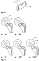
- the conically shaped neck 54 can translatingly be moved in the forward or backward direction by rotating the handle or dial 58. This allows adjusting the respective dimensions for y and z (see Fig 13 a to e) in order to manufacture the different sizes ranging from "S" to "XXL” per Table 2.
- the coating material is cast into the first mould portion 30 and the second mould portion 40.
- the two mould portions 30 and 40 are then joined.
- Advantageously bolts or studs (not shown in the drawings) are used for tightening and pressing the two mould portions 30 and 40 tightly against each other.
- the fine thread 53 in the bolt 51 is preferably self-locking, so that the bolt 51 cannot dislocate due to the pressure of the mould portions or any exothermal solidification process of the coating material. This ensures compliance with the respective sizes.
- positioning devices 57 e.g. in the form of C-shaped or slotted washers 57 of different thicknesses may be provided and may advantageously be identified with e.g.: S, M, L, XL und XXL. These positioning washers 57 are form-fittingly inserted at the end between the sleeve 52 and the bolt 51.
- the first mould portion 30 and the second mould portion 40 are separated.
- the finished prosthesis head 20 can then be removed from the mould portions 30 and 40. It may be advantageous to release any tension between the conical neck 54 and the core element 25 prior to removing the finished prosthesis head 20 by rotating the handle 58 on the threaded end section 59 of the cylindrical bolt 51, in order to separate of the PMMA coated core element 25 from the conical neck 54.
- the prosthesis head may be removed and be replaced by a definitive implant head.
- the hip joint socket is again placed into the pelvic bone.
Landscapes
- Health & Medical Sciences (AREA)
- Orthopedic Medicine & Surgery (AREA)
- Cardiology (AREA)
- Oral & Maxillofacial Surgery (AREA)
- Transplantation (AREA)
- Engineering & Computer Science (AREA)
- Biomedical Technology (AREA)
- Heart & Thoracic Surgery (AREA)
- Vascular Medicine (AREA)
- Life Sciences & Earth Sciences (AREA)
- Animal Behavior & Ethology (AREA)
- General Health & Medical Sciences (AREA)
- Public Health (AREA)
- Veterinary Medicine (AREA)
- Prostheses (AREA)
Description
- The present invention relates to device for manufacturing a prosthesis head, and more particularly a temporary prosthesis head for a hip implant. Moreover the present invention relates to a method of manufacturing a prosthesis head, and more particularly to a method of manufacturing a temporary prosthesis head for a hip implant.
- In conventional hip joint replacement the femoral head is replaced by a femoral implant with an artificial implant head. In the same operation, the acetabulum, i.e. the hip socket in the pelvic bone, is excavated and receives an acetabular cup adapted for engaging with the head of the femoral implant. Although this is increasingly becoming a standard procedure, with about 300,000 cases per year in the U.S. alone, it is estimated that about 1.5 per cent of the patients suffer from an infection following this surgery. The conventional treatment for these infections foresees removing the implanted acetabular cup from the acetabulum as well as removing the femoral implant from the femur. The femoral implant is entirely replaced by a temporary implant, known in the art as a "spacer", during the recovery period. Once the infection has healed, the acetabular cup is re-implanted in the pelvic bone, and the spacer is again removed from the femur and replaced by the permanent femoral implant.
-
Fig. 1 shows a cross section of the typical post hip replacement situation. As is known in the art, afemoral prosthesis 10 generally comprises afemoral implant body 11 with a distal end embedded in the femur and aproximal end 13 located adjacent the patient's hip joint. Animplant neck 14 protrudes in the proximal direction from theproximal end 13 of thefemoral implant body 11. Theimplant neck 14 may have a tapered proximal end, such as a Morse taper, as is known in the art, to accommodate a substantiallyspherical prosthesis head 15. Theprosthesis head 15 is provided with a matchingtapered socket 16 and can be pushed onto theimplant neck 14. Theprosthesis head 15 and theimplant neck 14 are then retained by friction. Theprosthesis head 15 typically takes the form of a joint ball or bearing, sometimes with a cylindrical protrusion in the form of ahub 17 extending in the distal direction, surrounding thetapered socket 16 for receiving and engaging with theimplant neck 14. The prosthesis head 15 rests against anacetabular cup 18 which has been implanted into thepelvic bone 19. In general, such anacetabular cup 18 comprises an inlay, typically made from polyethylene (PE), ceramics, or other suitable inert materials known in the art for this purpose. Theacetabular cup 18 essentially has the shape of a concave, or hollow, half-sphere. The external diameter of thespherical prosthesis head 15 is adapted to and essentially corresponds to the inner diameter of the inlay of theacetabular cup 18. It is further known to provide the acetabular cup with an inlay that is usually selected from polyethylene (PE), porcelain, or ceramics. Together, the prosthesis head 15 and theacetabular cup 18 form the new hip joint. - In an alternative embodiment, it is known to provide the
acetabular cup 18 in a conical form. - When a complication, such as an infection of the pelvic bone, occurs, the typical treatment foresees the temporary removal of the implanted
acetabular cup 18 as well as the entirefemoral implant body 11. A temporary implant, known as "spacer" in the art, is then embedded in the femur. It is noted that, during the healing period, noacetabular cup 18 is present, and the head of the spacer or of the temporary implant rests in direct contact with the pelvic bone. The head of the spacer is therefore dimensioned to fill the cavity vacated by removing the implanted acetabular cup from the pelvic bone. Frequently the spacer body is made from biocompatible material, such as poly methyl methacrylate (PMMA), and it may further comprise one or more pharmaceutically active substances, such as an antibiotic or antimycotic, which are released from the spacer material over time. -
Fig. 2 shows an alternative form of aprosthesis head 15 that is also known in the art. In contrast with the illustration ofFig. 1 , theprosthesis head 15 is without a cylindrical hub extending in the distal direction. Animplant neck 14 protrudes in the proximal direction from thefemoral implant body 11. In the absence of a cylindrical hub, it is thetapered socket 16 provided inside theprosthesis head 15 which receives and engages with theimplant neck 14. Thetapered socket 16 can be pushed onto the matchingimplant neck 14. Theprosthesis head 15 and theimplant neck 14 are then retained by friction. Theprosthesis head 15 typically takes the form of a joint ball or bearing. - However, the removal of the implant from the femur places this bone at increased risk of mechanical or other damage, which may be permanent. Moreover, being made from PMMA or other similar materials, the known temporary spacer suffers from a lack of mechanical strength which may result in dislocation, loosening and, in the extreme, breakages. In particular a breakage necessitates a surgical removal of the spacer, which is a severe complication that further inconveniences the patients.
- Consequently, there is a need to address the deficiencies that exist in the current state of the art with regard to conventional approaches. Such deficiencies and other needs are addressed by one or more of the various embodiments of the present invention. It is therefore an object of the present invention to overcome or at least ameliorate one or more of the deficiencies that are identified hereinabove. It is further an object of certain embodiments of the present invention to increase the mechanical strength of the implant whilst at the same time allowing to treat the infected hip. It is another object of certain embodiments of the present invention to reduce the inconvenience to the patient resulting from follow-up surgery following infection.
- The closest prior art is disclosed in
WO 2009/073781 which discloses a device for manufacturing a prosthesis head according to the preamble of claim 1, and inUS 2009/175978 which discloses a method according to the preamble of claim 6. - The present invention is based on the realisation that it is sometimes not possible or advisable to remove the entire implant. In accordance with the present invention it is therefore proposed to remove the acetabular cup from the infected site, to leave the femoral implant in place within the femur and to merely replace the implant head by a temporary prosthesis head, or spacer head.
- According the present invention there is provided a device for manufacturing a prosthesis head. The device comprises a mould and a core positioning element. The mould has a substantially spherical cavity, optionally in the form of a substantially spherical segment. A core positioning means has a longitudinal axis and comprises a first end. The first end is adapted for receiving a socket of a core element of a prosthesis head. The mould comprises means for receiving the core positioning means, so that the first end of the core positioning means rests within the substantially spherical mould cavity. The means for receiving the core positioning means further align the longitudinal axis of the core positioning means with a radial direction with respect to the spherical cavity.
- The core positioning means may further comprise means for adjusting in the longitudinal direction the position of the first end of the core positioning means. This allows the centre point of a core element received on the first end of the core positioning means to be displaced in the radial direction with respect to the centre point of the spherical mould cavity.
- The mould comprises a first mould portion and a second mould portion. The first mould portion may comprise a first substantially semi-spherical concave recess, optionally in the form of a substantially semi-spherical segment. The second mould portion may comprise a second substantially semi-spherical concave recess, optionally in the form of a substantially semi-spherical segment. The first mould portion and the second mould portion may be adapted for being placed in abutment with each other when in use, so that the semi-spherical concave recesses face each other and are aligned and placed in tight abutment, thereby forming an essentially spherical cavity for manufacturing a prosthesis head.
- In the first mould portion the means for aligning the longitudinal axis of the core positioning means comprise, according to the invention, a first substantially semi-cylindrical channel extending from the first substantially semi-spherical concave recess to an adjacent side wall.
- In the second mould portion the means for aligning the longitudinal axis of the core positioning means comprise, according to the invention, a second substantially semi-cylindrical channel extending from the second substantially semi-spherical concave recess to an adjacent side wall.
- The core positioning means may be of substantially the same diameter as the essentially semi-cylindrical concave recesses of the first and second mould portions.
- The core positioning means may comprise a neck portion at its proximal end for attaching a core element.
- The core positioning means may further comprise a bolt, wherein the neck portion is provided at the proximal end of the bolt.
- The core positioning means may further comprise means for adjusting the position of its neck portion to a predetermined position when placed into the substantially spherical cavity.
- The means for adjusting the position of the neck portion to a predetermined position may comprise an outer threading at the distal end of the bolt.
- According to another aspect of the present invention there is provided a method of manufacturing a prosthesis head, comprising the steps of
- a) providing a core element;
- b) providing a core positioning means having a longitudinal axis and comprising a first end, the first end adapted for receiving a socket of a core element of a prosthesis head;
- c) providing a mould, the mould comprising a substantially spherical cavity, wherein the mould further comprises means for receiving the core positioning means;
- d) attaching the core element to the first core positioning means end;
- e) introducing the core positioning means into the mould, so that the first end of the core positioning means rests within the spherical mould cavity and the longitudinal axis of the core positioning means is aligned with a radial direction with respect to the substantially spherical cavity; and
- f) filling the remainder of the substantially spherical cavity with a coating material for coating the core element.
- The step c) further comprises
- providing a first mould portion, the first mould portion comprising a first semi-spherical concave recess and a first semi-cylindrical channel extending from the first semi-spherical concave recess of the mould along the intersecting plane to a first proximal side wall; and
- providing a second mould portion, the second mould portion comprising a second semi-spherical concave recess and a second semi-cylindrical channel extending from the second semi-spherical concave recess of the mould along the intersecting plane to a second proximal side wall.
- The step b) may further comprise providing a core positioning means of substantially the same diameter as the first and second semi-cylindrical concave recesses of the first and second mould portions, the core positioning means comprising a neck portion for attaching a core element at the first end of the core positioning means.
- The step d) may further comprise attaching the core element to the neck portion of the first end of core positioning means.
- The step f) may further comprise the steps of:
- f1) providing a mouldable coating material;
- f2) inserting the mouldable coating material into the first and second semi-spherical concave recesses of the first and second mould portions;
- f3) inserting the core element into the mouldable material provided in the first semi-spherical concave recess of the first mould portion, such that the attached core positioning means is inserted into the first semi-cylindrical channel;
- f4) placing the second mould portion in abutment with the first mould portion so that the semi-spherical concave recesses face each other and are aligned and placed in tight abutment such that the semi-cylindrical concave channels are also aligned with each other, whereby the core element is inserted into the mouldable material provided in the second semi-spherical concave recess of the second mould portion,
- f5) allowing the mouldable coating material to cure;
- f6) separating the first mould portion from the second mould portion, and removing the core positioning means from the coated core element, such that a substantially spherical prosthesis head is obtained in the form of core element coated with a moulded outer coating.
- The axial position of the core element in the mould may be adjusted such that a desired axial displacement between the core element and the outer coating results.
The length of the core positioning means may be selected such that a desired axial displacement between the core element and the outer coating results. - The method may further comprise adjusting the length of the core positioning means.
The method may further comprise selecting a core positioning means of desired length.
The mouldable coating material may be selected from PMMA.
The mouldable coating material may comprises at least one pharmaceutically active component, optionally in the form of an antibiotic and/or antimycotic.
The core element may be selected from titanium. - Other objects, features, and advantages of the present invention will become more apparent from the following detailed description when read in conjunction with the accompanying drawings.
- These aspects and further embodiments of the present invention will now be described with reference to the following non-limiting Figures.
-
Fig 1 illustrates schematically a known implant body and prosthesis head. -
Fig 2 illustrates schematically a second example of a known implant body and prosthesis head. -
Fig 3 is a drawing of a first embodiment of a prosthesis head in accordance with the present invention. -
Fig 4 and Fig 5 show a detailed cross section of a second embodiment of a prosthesis head in accordance with the present invention. -
Fig 6 is an isometric view of a first mould portion in accordance with the present invention. -
Fig 7 is an isometric view of a second mould portion in accordance with the present invention. -
Figs 8A and 8B illustrate a cross-section and a top view of a core positioning means in accordance with the present invention, when placed into a first mould portion. -
Fig 9 is an isometric view of a core positioning means in accordance with the present invention, when placed into a first mould portion. -
Fig 10 is an isometric view of a bolt in accordance with the present invention. -
Fig 11 is an isometric view of a sleeve in accordance with the present invention. -
Fig 12 is an isometric view of a holding plate in accordance with the present invention. -
Figs 13 a) to e) are illustrations of the placement of the core element in the outer coating for different sizes of prosthesis heads in accordance with the present invention. - The present invention relates to mould for manufacturing a prosthesis head, and more particularly to a temporary prosthesis head for a hip implant. Moreover the present invention relates to a method of manufacturing a prosthesis head, more particularly a temporary prosthesis head for a hip implant. Particular embodiments will be described in the following with reference to the non-limiting drawings.
- The present invention is based on the concept that it is sometimes not possible or advisable to remove the entire implant. The inventors therefore proposed to leave the femoral implant in place in the femur and to merely remove the acetabular cup and replace the femoral implant head by a suitable prosthesis head in accordance with the present invention.
- A first example of a prosthesis head resulting from the present invention is illustrated in
Fig 3 . Afemoral prosthesis 10 generally comprises afemoral implant body 11 with a distal end embedded in the femur (not shown for simplicity) and aproximal end 13 located adjacent the patient's hip joint. Animplant neck 14 protrudes in the proximal direction from theproximal end 13 of thefemoral implant body 11. Theimplant neck 14 may have a tapered proximal end, such as a Morse taper, as is known in the art. - In accordance with a first aspect a
prosthesis head 20 for hip implants comprises acore element 25, which is surrounded by anouter coating 21. Thecore element 25 further comprises asocket 26, so that it is adapted for receiving a neck of a femoral implant body. It may be advantageous to provide thesocket 26 in the form of a blind bore. - The
socket 26 may preferably have a conical or tapered shape, so that is adapted for receiving a conical or tapered neck of a femoral implant body. - The
outer coating 21 of theprosthesis head 20 is of essentially spherical shape. Advantageously theouter coating 21 may have an essentially circular cut-out 22, which may be oriented to substantially coincide with thesocket 26 in thecore element 25.
In accordance with the geometry of the patient's anatomy, thecore element 25 and thecoating 21 may be displaced by a predetermined distance along the axis of thesocket 26. The calculation of this displacement is described in more detail below.
Inside thesocket 26 thecore element 25 may further comprise abore 27 of smaller diameter, as shown inFig 4 . Preferably thebore 27 may be provided in the form of a blind bore. Moreover, thebore 27 may be provided with a threading 28. The threading 28 allows thecore element 25 to be fixed to aneck 54 of a core positioning means 50 during manufacturing of theprosthesis head 20.
Thecore element 25 may preferably be selected from metal, optionally from titanium (Ti). It may further be preferred that thecore element 25 is essentially spherical, and more advantageously in the form of a spherical section.
The outer surface of thecore element 25 may further comprise a plurality ofrecesses 29. Theserecesses 29 may be provided in the form of a number of blind bores which may be distributed evenly or unevenly around the circumference of thecore element 25, as illustrated inFig 5 . Therecesses 29 allow theouter coating 21 to engage and interlock with the outer surface of thecore element 25 to form a mechanicallystable prosthesis head 20 during the manufacturing, respectively moulding process. - The
outer coating 21 of theprosthesis head 20 may be selected from plastics material, preferably from poly (methyl methacrylate) (PMMA). The plastics material selected forouter coating 21 may optionally comprise at least one pharmacologically active agent, preferably in the form of one of antibiotic or antimycotic. It will usually be preferred to provide theouter coating 21 in essentially spherical shape, and more advantageously in the form of a spherical section.
The diameter of theprosthesis head 20 is advantageously selected to essentially correspond to the diameter of the acetabular cavity after the acetabular cup has been removed from the infected site. - Referring again to the particular example shown in
Fig 3 , a prosthestic head, or spacer, 20 for hip implants comprises a substantiallyspherical core element 25 which is surrounded by anouter coating 21. Thecore element 25 further comprises asocket 26, so that it is adapted for receiving a neck of a femoral implant body. Thesocket 26 is in the form of a blind bore with a conical or tapered shape, so that is adapted for receiving a conical, or tapered neck of a femoral implant body. Theouter coating 21 of theprosthesis head 20 has a cut-out 22, which substantially coincides with thesocket 26 in thecore element 25. Inside thesocket 26 thecore element 25 further comprises abore 27 of smaller diameter. Thebore 27 has the form of a blind hole and is provided with aninternal threading 28. Theinternal threading 28 allows fixing thecore element 25 to a neck of a core positioning means during manufacturing of theprosthesis head 20. Thecore element 25 is selected from titanium (Ti). Moreover thecore element 25 is essentially spherical. The outer surface of thecore element 25 further comprises a plurality ofrecesses 29. Theserecesses 29 are provided in the form of a number of blind bores which may for instance be distributed in two circles around the circumference of thecore element 25. Therecesses 29 allow theouter coating 21 to engage and interlock with the outer surface of thecore element 25 to form a mechanicallystable prosthesis head 20. Theouter coating 21 of theprosthesis head 20 is selected from poly (methyl methacrylate) (PMMA). The plastics material selected forouter coating 21 may optionally comprise at least one pharmacologically active agent, preferably in the form of one of antibiotic or antimycotic. Furthermore, theouter coating 21 has an essentially spherical shape. - Referring to
Fig 1 and Fig 2 , the following dimensions have been obtained from conventional prosthesis implants:Table 1: dimensions of conventional implants S M L28 L32 XL XXL a + h [mm] 30.1 30.8 33.6 35.6 40 40.2 dext [mm] 28 28 28 32 32 28 Rest [mm] 11 11 11 9 9 11 x [mm] 1 1 1 1 1 1 htot [mm] 42.1 42.8 45.6 45.6 50 52.2 - The total height htot can be calculated from the measured values listed in Table 1 for the six different original sizes (labelled from "S" to "XXXL") of the prostheses, wherein:
- a = distance border of ball to prosthesis shoulder
- h = height of the
respective ball 15 - Rest = rsocket -dext /2 (ball radius)
- x = distance between socket joint and pelvic bone (approximately 1 mm)
- htot = (a + h) + Rest + x = height to be reached with the
spacer 20 of the present invention - Since it results that the total heights htot for the sizes L28 und L32 are the same, these have been allocated one standard size L, wherein the
index 28, respectively 32, denotes the respective ball diameters in millimetres for the originalfemoral prosthesis 10. The index is not relevant for the present invention and will be ignored in the following.
Thecore element 25, preferably in the form of a titanium ball, is arranged at a predetermined position on the conical part of theimplant neck 14. This neck geometry is fixed and cannot be varied. Accordingly, the only variation in geometry can be achieved by adjusting the internal configuration of the prosthesis head, wherein the sphericalouter coating 21 is displaced along the axial direction with respect to thecore element 25.
The total height h tot " (cf.Fig. 1 and Table 1) of the prosthesichead 20 is axially adjustable via the dimensions y and z, wherein the sum of y + z remains constant for each size of theprosthesis head 20. The dimensions y and z result from the axial placement of thecore element 25 in theouter coating 21. Likewise constant and due to construction are the dimensions a and h of thecore element 25, respectively the implant neck 14 (seeFigs. 1 and 2 ). For the purpose of clearer distinction the index "Ti" has been introduced for these two dimensions, aTi and hTi , in order to indicate that these relate to the new spacer construction in accordance with the present invention.Table 2: dimensions of the prosthesis heads in accordance with the present invention, so that for each size "htot " remains unchanged with respect to the corresponding dimensions given in Table 1 S M L28 L32 XL XXL aTi [mm] 12.9 12.9 12.9 12.9 12.9 12.9 hTi [mm] 27 27 27 27 27 27 htot [mm] 42.1 42.8 45.6 45.6 50 52.2 y [mm] 2.2 2.9 5.7 5.7 10.1 12.3 z [mm] 12.1 11.4 8.6 8.6 4.2 2 - The dimensions to be used for the
prosthesis head 20 in accordance with the present invention can then be calculated as: - y = h tot - (aTi + hTi)
- z = height of the mould (e.g. 41,3mm) - (y + hTi )
- In accordance with an aspect of the present invention, a device is proposed that allows the manufacturing of a prosthesis head.
-
Fig 6 shows a first portion of the manufacturing device in the form of afirst mould portion 30. Thefirst mould portion 30 is made from a substantially die-shaped block which comprises four sidewalls, afirst face 31 and a first rear face. Thefirst face 31 is arranged so that, when in use, it faces the second face of a second mould portion (described below with reference toFig 7 ). Advantageously, the block may be made from polytetrafluoroethylene (PTFE), also known as Teflon®. Of course, it is understood that other suitable materials might also be used. - As further illustrated in
Fig 6 , a substantiallysemi-spherical recess 32 is formed in the centre of thefirst face 31 of thefirst mould portion 30. Moreover, asemi-cylindrical recess 33 extends along thefirst face 31 towards anadjacent sidewall 34. Fourholes 35 are foreseen, extending vertically through thefirst face 31 and through thefirst mould portion 30. Theholes 35 are adapted for receiving fitting studs or bolts. - Moreover, a
rim 36 is provided along the length of the edges of thefirst face 31 as well as along the edge of the intersection of thesemi-spherical recess 32 and thesemi-cylindrical recess 33 with thefirst face 31, respectively. Therim 36 circumscribes a recessedplane 39 in thefirst face 31. In addition, agroove 37 is provided in a central section of therim 36, preferably diametrically opposite thesemi-cylindrical recess 33. Whilst therim 36 serves to ensure tight abutment with the other mould portion during the moulding process, the recessedplane 39 allows to collect excess coating material when, in use, the mould portions are tightly pressed together. -
Fig 7 shows a second portion of the manufacturing device in the form of asecond mould portion 40. Like thefirst mould portion 30, thesecond mould portion 40 is made from a substantially die-shaped block which comprises four sidewalls, asecond face 41 and a second rear face. Thesecond face 41 is arranged so that, when in use, it faces thefirst face 31 of the first mould portion 30 (described above with reference toFig 6 ). Advantageously, the block may be made from polytetrafluoroethylene (PTFE), also known as Teflon®. Of course, it is understood that other suitable materials might also be used. - As further illustrated in
Fig 7 , a substantiallysemi-spherical recess 42 is formed in the centre of thesecond face 41 of thesecond mould portion 40. Moreover, asemi-cylindrical recess 43 extends along thesecond face 41 towards anadjacent sidewall 44. Fourholes 45 are foreseen, extending vertically through thefirst face 41 and through thefirst mould portion 40. Theholes 45 are adapted for receiving fitting studs or bolts. - Moreover, a
rim 46 is provided along the length of the edges of thefirst face 41 as well as along the edge of the intersection of thesemi-spherical recess 42 and thesemi-cylindrical recess 43 with thesecond face 41, respectively. In addition, agroove 47 is provided in a central section of therim 46, preferably diametrically opposite thesemi-cylindrical recess 43. Therim 46 further circumscribes a recessedplane 49 in thefirst face 41. Whilst therim 46 serves to ensure tight abutment with the other mould portion, the recess allows to collect excess coating material when, in use, the mould portions are tightly pressed together. - Both the
first mould portion 30 and thesecond mould portion 40 each comprise semi-sphericalconcave recesses holes second mould portions first mould portion 30 and thesecond mould portion 40 and hold them in tight abutment. - Referring now to
Fig 8A and Fig 8B , a core positioning means 50 is adapted for being inserted into thesemi-spherical recesses second mould portions cylindrical bolt 51. At one end thebolt 51 features a taperedbolt neck 54 which is adapted for being inserted into the matching socket of thecore element 25. At the end of the tapered bolt neck 54 a threadedend section 59 is provided for being screwed into a corresponding internal threading provided in thecore element 25. Around a central part of thebolt 51, anexternal threading 53 is provided. At the other end, thebolt 51 is provided with a handle or dial 58. The core positioning means further comprises asleeve 52 which surrounds thebolt 51, but leaves thebolt neck 54 free. The external diameter of the sleeve substantially corresponds with the internal diameter of thesemi-cylindrical recesses second mould portions bolt 51. Agroove 56 is foreseen around the circumference of thesleeve 52. Thegroove 56 serves to fix the position of the sleeve with respect to a holdingplate 61, which is attached to a sidewall of the first mould portion. The length of thesleeve 52 is selected such that is leaves a section of the bolt adjacent the handle or dial 58 free. This allows a position-settingwasher 57 to be fitted to the free section of thebolt 51. Thesleeve 52 further comprises aninternal threading 55 adapted for engaging with the external threading 53 of thebolt 51. When thebolt 51 is inserted into thesleeve 52, theinternal threading 55 engages with the external threading 53 of thebolt 51. By rotating the handle or dial 58, the position of thebolt neck 54 with respect to thesleeve 52 can be adjusted. -
Fig 9 illustrates thefirst mould portion 30 with a holdingplate 61, into which the core positioning means 50 has been inserted. Acore element 25 is shown attached to the bolt neck. A C-shaped or slotted position-settingwasher 57 is fitted to the free section of thebolt 51, shown inFig 10 . By rotating the handle or dial 58, the position of the bolt neck can be adjusted with respect to thesleeve 52 to correspond to the thickness of the position-settingwasher 57. The thickness of theposition setting washer 57 thus allows setting the position of thebolt neck 54, seeFig 10 , and therefore also the position of thecore element 25 withinsemi-spherical recess 32 of thefirst mould portion 30. - The
cylindrical bolt 51 is shown inFig 10 . At one end thebolt 51 features a taperedbolt neck 54 which is adapted for being inserted into the matching socket of thecore element 25. At the end of the tapered bolt neck 54 a threadedend section 59 is provided for being screwed into a corresponding internal threading provided in thecore element 25. Around a central part of thebolt 51, anexternal threading 53 is provided which is adapted for engaging with the internal threading 55 of thesleeve 52. At the end of thebolt 51 opposite thebolt neck 54, a handle or dial 58 is provided. - As illustrated in
Fig 11 agroove 56 is foreseen around the circumference of thesleeve 52. Thegroove 56 serves to fix the position of the sleeve with respect to a holdingplate 61, which is attached to a sidewall of the first mould portion. The external diameter of the sleeve substantially corresponds with the diameter of the semi-cylindrical recesses and in the first and second mould portions. The internal diameter of thesleeve 52 essentially corresponds to the external diameter of thebolt 51. Thereby thegroove 56 of thesleeve 52 engages with the holding plate, which secures thesleeve 52 against a translational movement in the axial direction. The length of thesleeve 52 is selected such that it leaves a section of the bolt adjacent the handle or dial 58 free. Thesleeve 52 further comprises aninternal threading 55 adapted for engaging with the external threading 53 of thebolt 51. -
Fig 12 is an isometric representation of the holdingplate 61. As described above with reference toFig 8A and Fig 8B , the holdingplate 61 is mounted to asidewall 34 of thefirst mould portion 30 by means of fitting studs or bolts passing throughlong holes 62 provided in the holdingplate 61. The fitting studs or bolts are attached to corresponding bore holes 38 provided in thesidewall 34 of thefirst mould portion 30. In order to hold thegroove 56 in a predetermined position, the holdingplate 61 is provided with asemi-circular recess 63, which substantially corresponds in diameter to the diameter of thegroove 56 in thesleeve 52. Additionally, the thickness of the holdingplate 61 is chosen to essentially match the width of thegroove 56 in the axial direction. - In order to allow different positions to be set, a number of
washers 57 of different thicknesses may be provided. It may be advantageous to use various predetermined washer thicknesses in order to produce the different sizes corresponding to the values determined in Table 1 and 2. The distance-settingwasher 57 is attached to the distal end of thecylindrical bolt 51 and is locked into place by adial 58 which from the second end of thecylindrical bolt 51. - As shown in
Fig. 6 and 7 , both thefirst mould 30 and thesecond mould 40 each comprise asemi-cylindrical channel proximal side wall first mould 30 and thesecond mould 40 face each other and are placed into abutment, these semi-cylindricalconcave channels sleeve 52 and thecylindrical channel - At the proximal end of the
first mould 30, a holdingplate 61 is provided for supporting the part of thesleeve 52 that extends beyond the edge of thefirst mould 30. - It is understood by those skilled in the art that other distance setting means may be used without departing from the present invention. It may, e.g. be preferred to use core positioning means of different predetermined lengths instead of washers of different thickness. The effect, however, remains the same: the axial position of the core positioning means
neck 54, and thereby also the position of thecore element 25 within the moulds can be precisely determined prior to moulding. - The device comprising the first and
second mould portions outer coating 21 around thecore element 25. Thecore element 25 is preferably chosen to be titanium of grade 2, which is destined for medical purposes. The material for casting theouter coating 21 is preferably chosen from biocompatible material, such as poly methyl methacrylate (PMMA), which is suitable for medical purposes. The material chosen forouter coating 21 may further comprise one or more pharmaceutically active substances, such as an antibiotic or antimycotic, which may be released from the material over time. - The device used for casting comprises a
first mould portion 30 and asecond mould portion 40. It is advantageous to choose e.g. polytetrafluoroethylene (PTFE), also known as Teflon®, polyoxymethylene (POM-C) otherwise known as acetal copolymer, or another suitable material for thefirst mould portion 30 and thesecond mould portion 40. Of course, it is understood that other suitable materials might alternatively be used. - The
core element 25 is attached to a core positioning means 50 with a conically-shapedneck 54. This conically shapedneck 54 has exactly the same angle as theimplant neck 14 used in hip implants. Theneck 54 further comprises a threadedend section 59 with a thread to which thecore element 25 can be tightly screwed. - Since the
core element 25 is always arranged at the same position on the conically shapedneck 54, the conically shapedneck 54 can translatingly be moved in the forward or backward direction by rotating the handle or dial 58. This allows adjusting the respective dimensions for y and z (seeFig 13 a to e) in order to manufacture the different sizes ranging from "S" to "XXL" per Table 2. - For manufacturing, the coating material is cast into the
first mould portion 30 and thesecond mould portion 40. The twomould portions mould portions - The
fine thread 53 in thebolt 51 is preferably self-locking, so that thebolt 51 cannot dislocate due to the pressure of the mould portions or any exothermal solidification process of the coating material. This ensures compliance with the respective sizes. For easier handling,positioning devices 57, e.g. in the form of C-shaped or slottedwashers 57 of different thicknesses may be provided and may advantageously be identified with e.g.: S, M, L, XL und XXL. Thesepositioning washers 57 are form-fittingly inserted at the end between thesleeve 52 and thebolt 51. - After expiry of the dwell period the
first mould portion 30 and thesecond mould portion 40 are separated. Thefinished prosthesis head 20 can then be removed from themould portions conical neck 54 and thecore element 25 prior to removing thefinished prosthesis head 20 by rotating thehandle 58 on the threadedend section 59 of thecylindrical bolt 51, in order to separate of the PMMA coatedcore element 25 from theconical neck 54. - It may often not be advisable, or even possible, to remove the entire implant, when the infection is restricted to the acetabulum or when the removal of the implant out of the femur is live threatening.
- In accordance with a further aspect of the present invention it is therefore proposed to leave the main body of the implant in place in the femur in these cases and to merely replace the original implant head by a prosthesis head which has been obtained in accordance with the present invention. At the same time, the acetabular cup is removed from the pelvic bone.
- Once the infection has healed, the prosthesis head may be removed and be replaced by a definitive implant head. At the same time, the hip joint socket is again placed into the pelvic bone.
- While the technique presented herein has been described in relation to its preferred embodiments, it is to be understood that this description is for illustrative purposes only. It will be appreciated by the person of skill in the art that various modifications may be made to the above described embodiments without departing from the scope of the present invention. Accordingly, it is intended that the invention be limited only by the scope of the claims appended hereto.
List of reference numbers 10 femoral prosthesis 37 groove 11 femoral implant body 39 recessed plane 13 proximal end 40 second mould portion 14 implant neck 41 second face 15 prosthesis head 42 semi-spherical recess 16 tapered socket 43 semi-cylindrical recess 17 cylindrical protrusion 44 adjacent sidewall 18 hip socket joint 45 hole 19 pelvic bone 46 rim 20 prosthesis head 47 groove 21 outer coating 49 recessed plane 22 cut-out 50 core positioning means 25 core element 51 cylindrical bolt 26 socket 52 sleeve 27 bore 53 external threading 28 threading 54 bolt neck 29 recess 55 internal threading 30 first mould portion 56 groove 31 first face 57 position-setting washer 32 semi-spherical recess 58 handle or dial 33 semi-cylindrical recess 59 threaded end section 34 adjacent sidewall 61 holding plate 35 hole 62 long hole 36 rim 63 semi-circular recess
Claims (12)
- A device for manufacturing a prosthesis head, the device comprisinga mould (30, 40), the mould comprising a first mould portion (30) and a second mould portion (40) and a substantially spherical cavity (32, 42), optionally in the form of a substantially spherical segment;a core positioning means (50) having a longitudinal axis and comprising a first end (54), the first end (54) adapted for receiving a socket of a core element of a prosthesis head;wherein the mould (30, 40) comprises means (33, 43) for receiving the core positioning means (50), so that the first end (54) of the core positioning means (50) rests within the substantially spherical mould cavity (32, 42), andwherein the means (33, 43) further align the longitudinal axis of the core positioning means (50) with a radial direction with respect to the spherical cavity (32, 42), characterized in that
the means (33, 43) for aligning the longitudinal axis of the core positioning means (50) comprisein the first mould portion (30), a first semi-cylindrical channel (33) extending from the first semi-spherical concave recess (32) to an adjacent side wall (34); andin the second mould portion (40), a second semi-cylindrical channel (43) extending from the second semi-spherical concave recess (42) to an adjacent side wall (44). - The device of claim 1, wherein the core positioning means (50) is of substantially the same diameter as the semi-cylindrical channels (33, 43) of the first and second mould portions (30, 40), and wherein the core positioning means (50) comprises a neck portion at its proximal end (54) for attaching a core element.
- The device of claim 2, wherein the core positioning means (50) further comprises a bolt (51), wherein the neck portion is provided at the proximal end (54) of the bolt (51).
- The device of any one of claims 2 to 3, wherein the core positioning means (50) further comprises means for adjusting the position of its neck portion (54) to a predetermined position when placed into the substantially spherical cavity (32, 42).
- The device of claim 4, wherein the means for adjusting the position of the neck portion (54) to a predetermined position comprise an outer threading at the distal end of the bolt (51).
- A method of manufacturing a prosthesis head, the method comprising the steps of:a) providing a core element (25);b) providing a core positioning means (50) having a longitudinal axis and comprising a first end (54), the first end (54) adapted for receiving a socket of a core element of a prosthesis head;c) providing a mould (30, 40), the mould comprising a substantially spherical cavity (32, 42), wherein the mould (30, 40) further comprises means (33, 43) for receiving the core positioning means (50);d) attaching the core element (25) to the first core positioning means end (54);e) introducing the core positioning means into the mould (30, 40), so that the first end (54) of the core positioning means (50) rests within the substantially spherical mould cavity (32, 42) and the longitudinal axis of the core positioning means (50) is aligned with a radial direction with respect to the substantially spherical cavity (32, 42); andf) filling the remainder of the spherical cavity (32, 42) with a coating material for coating the core element (25),characterized in that step c) further comprisesproviding a first mould portion (30), the first mould portion comprising a first semi-spherical concave recess (32) and a first semi-cylindrical channel (33) extending from the first semi-spherical concave recess (32) of the mould along the intersecting plane to a first proximal side wall (34); andproviding a second mould portion (40), the second mould portion comprising a second semi-spherical concave recess (42) and a second semi-cylindrical channel (43) extending from the second semi-spherical concave recess (42) of the mould along the intersecting plane to a second proximal side wall (44).
- The method of claim 6, wherein step b) further comprisesproviding a core positioning means (50) of substantially the same diameter as the first and second semi-cylindrical concave recesses (33, 43) of the first and second mould portions (30, 40), the core positioning means (50) comprising a neck portion for attaching a core element (25) at the first end (54) of the core positioning means (50).
- The method of any one of claims 6 and 7, wherein step d) further comprisesattaching the core element (25) to the neck portion of the first end (54) of core positioning means (50).
- The method of any one of claims 6 to 8, wherein step f) further comprisesf1) providing a mouldable coating material;f2) inserting the mouldable coating material into the first and second semi-spherical concave recesses (32, 42) of the first and second mould portions (30, 40);f3) inserting the core element (25) into the mouldable material provided in the first semi-spherical concave recess (32) of the first mould portion (30), such that the attached core positioning means (50) is inserted into the first semi-cylindrical channel (33);f4) placing the second mould portion (40) in abutment with the first mould portion (30) so that the semi-spherical concave recesses (32, 42) face each other and are aligned and placed in tight abutment such that the semi-cylindrical concave channels (33, 43) are also aligned with each other, whereby the core element (25) is inserted into the mouldable material provided in the second semi-spherical concave recess (42) of the second mould portion (40),f5) allowing the mouldable coating material to cure;f6) separating the first mould portion (30) from the second mould portion (40), and removing the core positioning means (50) from the coated core element (25), such that a substantially spherical prosthesis head (20) is obtained in the form of core element (25) coated with a moulded outer coating (21).
- The method of claim 9, wherein the length of the core positioning means (50) is selected such that a desired axial displacement between the core element (25) and the outer coating (21) results.
- The method of claim 10, further comprising adjusting the length of the core positioning means (50).
- The method of claim 10, further comprising selecting a core positioning means (50) of desired length.
Applications Claiming Priority (2)
| Application Number | Priority Date | Filing Date | Title |
|---|---|---|---|
| LU92093A LU92093B1 (en) | 2012-11-12 | 2012-11-12 | Prosthesis head |
| PCT/EP2013/003403 WO2014072076A1 (en) | 2012-11-12 | 2013-11-12 | Temporary prosthesis head |
Publications (2)
| Publication Number | Publication Date |
|---|---|
| EP2916775A1 EP2916775A1 (en) | 2015-09-16 |
| EP2916775B1 true EP2916775B1 (en) | 2017-06-07 |
Family
ID=47430010
Family Applications (1)
| Application Number | Title | Priority Date | Filing Date |
|---|---|---|---|
| EP13802531.7A Not-in-force EP2916775B1 (en) | 2012-11-12 | 2013-11-12 | Temporary prosthesis head |
Country Status (3)
| Country | Link |
|---|---|
| EP (1) | EP2916775B1 (en) |
| LU (1) | LU92093B1 (en) |
| WO (1) | WO2014072076A1 (en) |
Families Citing this family (2)
| Publication number | Priority date | Publication date | Assignee | Title |
|---|---|---|---|---|
| IT201700048295A1 (en) * | 2017-05-04 | 2018-11-04 | G21 S R L | Mold and method for forming an orthopedic spacer in medical cement. |
| EP4324431A3 (en) * | 2018-03-07 | 2024-05-22 | Cossington Limited | Acetabular spacer device comprising a pharmaceutical substance |
Family Cites Families (6)
| Publication number | Priority date | Publication date | Assignee | Title |
|---|---|---|---|---|
| DE10156610C2 (en) * | 2001-11-13 | 2003-10-09 | Eska Implants Gmbh & Co | Pairing a joint ball with a sliding partner of a spherical cup |
| US7789646B2 (en) * | 2007-12-07 | 2010-09-07 | Zimmer Orthopaedic Surgical Products, Inc. | Spacer mold and methods therefor |
| US8206143B2 (en) * | 2007-12-13 | 2012-06-26 | Biomet Manufacturing Corp. | Modular articulating cement spacer |
| US7637729B2 (en) * | 2007-12-13 | 2009-12-29 | Biomet Manufacturing Corp. | Modular articulating cement spacer mold |
| PL2326287T3 (en) * | 2008-08-06 | 2017-03-31 | Tecres S.P.A. | Modular spacer device for treatment of arthro-prothesis infections |
| DE202009012964U1 (en) * | 2009-09-28 | 2010-03-18 | Medizinische Hochschule Hannover - Anstalt des öffentlichen Rechts | Casting mold for a cement large head for total hip arthroplasty |
-
2012
- 2012-11-12 LU LU92093A patent/LU92093B1/en active
-
2013
- 2013-11-12 WO PCT/EP2013/003403 patent/WO2014072076A1/en not_active Ceased
- 2013-11-12 EP EP13802531.7A patent/EP2916775B1/en not_active Not-in-force
Also Published As
| Publication number | Publication date |
|---|---|
| LU92093B1 (en) | 2014-05-13 |
| WO2014072076A1 (en) | 2014-05-15 |
| EP2916775A1 (en) | 2015-09-16 |
Similar Documents
| Publication | Publication Date | Title |
|---|---|---|
| KR102351799B1 (en) | A spacer device for treating joints in the human body | |
| EP2214595B1 (en) | Implant assembly | |
| RU2555131C2 (en) | Prosthesis for implantation into iliac canal | |
| US9795486B2 (en) | Modular spacer device for the treatment of prosthesis infections | |
| CN105997308B (en) | For producing the sept mould and method of hip sept | |
| US8926707B2 (en) | Femoral implant | |
| KR102580753B1 (en) | Acetabular spacer device containing pharmaceutical substances | |
| EP3753531A1 (en) | Hydrogel implants with porous materials | |
| JP7353761B2 (en) | Orthopedic implant with porous structural member | |
| WO2012126475A1 (en) | Dental abutment for oral scanning | |
| US20170252492A1 (en) | Fixation of orthopaedic devices | |
| US20100185298A1 (en) | Acetabular Spacer for Treatment of Hip Sepsis | |
| EP3215065A1 (en) | Improved adjustable modular spacer device for the articulation of the knee | |
| WO2014072076A1 (en) | Temporary prosthesis head | |
| US11298236B2 (en) | Devices and methods for cementing insert bearing liner into acetabular cup component | |
| US11185415B2 (en) | Mould for realizing a temporary prosthesis of hip or shoulder, and method thereof | |
| US12551347B2 (en) | Apparatus and method for forming a custom cement-on-cement articulating hip spacer | |
| EP4046589A1 (en) | Dental implant assemblies, tools therefor and kit |
Legal Events
| Date | Code | Title | Description |
|---|---|---|---|
| PUAI | Public reference made under article 153(3) epc to a published international application that has entered the european phase |
Free format text: ORIGINAL CODE: 0009012 |
|
| 17P | Request for examination filed |
Effective date: 20150608 |
|
| AK | Designated contracting states |
Kind code of ref document: A1 Designated state(s): AL AT BE BG CH CY CZ DE DK EE ES FI FR GB GR HR HU IE IS IT LI LT LU LV MC MK MT NL NO PL PT RO RS SE SI SK SM TR |
|
| AX | Request for extension of the european patent |
Extension state: BA ME |
|
| RIN1 | Information on inventor provided before grant (corrected) |
Inventor name: MAAS, STEFAN Inventor name: COLLE, CLAUDE Inventor name: KELM, JENS |
|
| DAX | Request for extension of the european patent (deleted) | ||
| GRAP | Despatch of communication of intention to grant a patent |
Free format text: ORIGINAL CODE: EPIDOSNIGR1 |
|
| INTG | Intention to grant announced |
Effective date: 20170103 |
|
| GRAS | Grant fee paid |
Free format text: ORIGINAL CODE: EPIDOSNIGR3 |
|
| AK | Designated contracting states |
Kind code of ref document: B1 Designated state(s): AL AT BE BG CH CY CZ DE DK EE ES FI FR GB GR HR HU IE IS IT LI LT LU LV MC MK MT NL NO PL PT RO RS SE SI SK SM TR |
|
| REG | Reference to a national code |
Ref country code: GB Ref legal event code: FG4D |
|
| GRAA | (expected) grant |
Free format text: ORIGINAL CODE: 0009210 |
|
| REG | Reference to a national code |
Ref country code: CH Ref legal event code: EP Ref country code: AT Ref legal event code: REF Ref document number: 898648 Country of ref document: AT Kind code of ref document: T Effective date: 20170615 |
|
| STAA | Information on the status of an ep patent application or granted ep patent |
Free format text: STATUS: THE PATENT HAS BEEN GRANTED |
|
| REG | Reference to a national code |
Ref country code: IE Ref legal event code: FG4D |
|
| REG | Reference to a national code |
Ref country code: DE Ref legal event code: R096 Ref document number: 602013022057 Country of ref document: DE |
|
| REG | Reference to a national code |
Ref country code: NL Ref legal event code: MP Effective date: 20170607 |
|
| REG | Reference to a national code |
Ref country code: LT Ref legal event code: MG4D |
|
| PG25 | Lapsed in a contracting state [announced via postgrant information from national office to epo] |
Ref country code: FI Free format text: LAPSE BECAUSE OF FAILURE TO SUBMIT A TRANSLATION OF THE DESCRIPTION OR TO PAY THE FEE WITHIN THE PRESCRIBED TIME-LIMIT Effective date: 20170607 Ref country code: HR Free format text: LAPSE BECAUSE OF FAILURE TO SUBMIT A TRANSLATION OF THE DESCRIPTION OR TO PAY THE FEE WITHIN THE PRESCRIBED TIME-LIMIT Effective date: 20170607 Ref country code: NO Free format text: LAPSE BECAUSE OF FAILURE TO SUBMIT A TRANSLATION OF THE DESCRIPTION OR TO PAY THE FEE WITHIN THE PRESCRIBED TIME-LIMIT Effective date: 20170907 Ref country code: ES Free format text: LAPSE BECAUSE OF FAILURE TO SUBMIT A TRANSLATION OF THE DESCRIPTION OR TO PAY THE FEE WITHIN THE PRESCRIBED TIME-LIMIT Effective date: 20170607 Ref country code: GR Free format text: LAPSE BECAUSE OF FAILURE TO SUBMIT A TRANSLATION OF THE DESCRIPTION OR TO PAY THE FEE WITHIN THE PRESCRIBED TIME-LIMIT Effective date: 20170908 Ref country code: LT Free format text: LAPSE BECAUSE OF FAILURE TO SUBMIT A TRANSLATION OF THE DESCRIPTION OR TO PAY THE FEE WITHIN THE PRESCRIBED TIME-LIMIT Effective date: 20170607 |
|
| REG | Reference to a national code |
Ref country code: AT Ref legal event code: MK05 Ref document number: 898648 Country of ref document: AT Kind code of ref document: T Effective date: 20170607 |
|
| PG25 | Lapsed in a contracting state [announced via postgrant information from national office to epo] |
Ref country code: LV Free format text: LAPSE BECAUSE OF FAILURE TO SUBMIT A TRANSLATION OF THE DESCRIPTION OR TO PAY THE FEE WITHIN THE PRESCRIBED TIME-LIMIT Effective date: 20170607 Ref country code: NL Free format text: LAPSE BECAUSE OF FAILURE TO SUBMIT A TRANSLATION OF THE DESCRIPTION OR TO PAY THE FEE WITHIN THE PRESCRIBED TIME-LIMIT Effective date: 20170607 Ref country code: BG Free format text: LAPSE BECAUSE OF FAILURE TO SUBMIT A TRANSLATION OF THE DESCRIPTION OR TO PAY THE FEE WITHIN THE PRESCRIBED TIME-LIMIT Effective date: 20170907 Ref country code: SE Free format text: LAPSE BECAUSE OF FAILURE TO SUBMIT A TRANSLATION OF THE DESCRIPTION OR TO PAY THE FEE WITHIN THE PRESCRIBED TIME-LIMIT Effective date: 20170607 Ref country code: RS Free format text: LAPSE BECAUSE OF FAILURE TO SUBMIT A TRANSLATION OF THE DESCRIPTION OR TO PAY THE FEE WITHIN THE PRESCRIBED TIME-LIMIT Effective date: 20170607 |
|
| PG25 | Lapsed in a contracting state [announced via postgrant information from national office to epo] |
Ref country code: EE Free format text: LAPSE BECAUSE OF FAILURE TO SUBMIT A TRANSLATION OF THE DESCRIPTION OR TO PAY THE FEE WITHIN THE PRESCRIBED TIME-LIMIT Effective date: 20170607 Ref country code: CZ Free format text: LAPSE BECAUSE OF FAILURE TO SUBMIT A TRANSLATION OF THE DESCRIPTION OR TO PAY THE FEE WITHIN THE PRESCRIBED TIME-LIMIT Effective date: 20170607 Ref country code: RO Free format text: LAPSE BECAUSE OF FAILURE TO SUBMIT A TRANSLATION OF THE DESCRIPTION OR TO PAY THE FEE WITHIN THE PRESCRIBED TIME-LIMIT Effective date: 20170607 Ref country code: AT Free format text: LAPSE BECAUSE OF FAILURE TO SUBMIT A TRANSLATION OF THE DESCRIPTION OR TO PAY THE FEE WITHIN THE PRESCRIBED TIME-LIMIT Effective date: 20170607 Ref country code: SK Free format text: LAPSE BECAUSE OF FAILURE TO SUBMIT A TRANSLATION OF THE DESCRIPTION OR TO PAY THE FEE WITHIN THE PRESCRIBED TIME-LIMIT Effective date: 20170607 |
|
| PG25 | Lapsed in a contracting state [announced via postgrant information from national office to epo] |
Ref country code: IS Free format text: LAPSE BECAUSE OF FAILURE TO SUBMIT A TRANSLATION OF THE DESCRIPTION OR TO PAY THE FEE WITHIN THE PRESCRIBED TIME-LIMIT Effective date: 20171007 Ref country code: SM Free format text: LAPSE BECAUSE OF FAILURE TO SUBMIT A TRANSLATION OF THE DESCRIPTION OR TO PAY THE FEE WITHIN THE PRESCRIBED TIME-LIMIT Effective date: 20170607 Ref country code: IT Free format text: LAPSE BECAUSE OF FAILURE TO SUBMIT A TRANSLATION OF THE DESCRIPTION OR TO PAY THE FEE WITHIN THE PRESCRIBED TIME-LIMIT Effective date: 20170607 Ref country code: PL Free format text: LAPSE BECAUSE OF FAILURE TO SUBMIT A TRANSLATION OF THE DESCRIPTION OR TO PAY THE FEE WITHIN THE PRESCRIBED TIME-LIMIT Effective date: 20170607 |
|
| REG | Reference to a national code |
Ref country code: DE Ref legal event code: R097 Ref document number: 602013022057 Country of ref document: DE |
|
| PLBE | No opposition filed within time limit |
Free format text: ORIGINAL CODE: 0009261 |
|
| STAA | Information on the status of an ep patent application or granted ep patent |
Free format text: STATUS: NO OPPOSITION FILED WITHIN TIME LIMIT |
|
| PG25 | Lapsed in a contracting state [announced via postgrant information from national office to epo] |
Ref country code: DK Free format text: LAPSE BECAUSE OF FAILURE TO SUBMIT A TRANSLATION OF THE DESCRIPTION OR TO PAY THE FEE WITHIN THE PRESCRIBED TIME-LIMIT Effective date: 20170607 |
|
| 26N | No opposition filed |
Effective date: 20180308 |
|
| PG25 | Lapsed in a contracting state [announced via postgrant information from national office to epo] |
Ref country code: SI Free format text: LAPSE BECAUSE OF FAILURE TO SUBMIT A TRANSLATION OF THE DESCRIPTION OR TO PAY THE FEE WITHIN THE PRESCRIBED TIME-LIMIT Effective date: 20170607 |
|
| REG | Reference to a national code |
Ref country code: DE Ref legal event code: R119 Ref document number: 602013022057 Country of ref document: DE |
|
| PG25 | Lapsed in a contracting state [announced via postgrant information from national office to epo] |
Ref country code: MC Free format text: LAPSE BECAUSE OF FAILURE TO SUBMIT A TRANSLATION OF THE DESCRIPTION OR TO PAY THE FEE WITHIN THE PRESCRIBED TIME-LIMIT Effective date: 20170607 |
|
| GBPC | Gb: european patent ceased through non-payment of renewal fee |
Effective date: 20171112 |
|
| PG25 | Lapsed in a contracting state [announced via postgrant information from national office to epo] |
Ref country code: CH Free format text: LAPSE BECAUSE OF NON-PAYMENT OF DUE FEES Effective date: 20171130 Ref country code: LI Free format text: LAPSE BECAUSE OF NON-PAYMENT OF DUE FEES Effective date: 20171130 |
|
| PG25 | Lapsed in a contracting state [announced via postgrant information from national office to epo] |
Ref country code: LU Free format text: LAPSE BECAUSE OF NON-PAYMENT OF DUE FEES Effective date: 20171112 |
|
| REG | Reference to a national code |
Ref country code: FR Ref legal event code: ST Effective date: 20180731 Ref country code: BE Ref legal event code: MM Effective date: 20171130 |
|
| REG | Reference to a national code |
Ref country code: IE Ref legal event code: MM4A |
|
| PG25 | Lapsed in a contracting state [announced via postgrant information from national office to epo] |
Ref country code: MT Free format text: LAPSE BECAUSE OF NON-PAYMENT OF DUE FEES Effective date: 20171112 |
|
| PG25 | Lapsed in a contracting state [announced via postgrant information from national office to epo] |
Ref country code: DE Free format text: LAPSE BECAUSE OF NON-PAYMENT OF DUE FEES Effective date: 20180602 Ref country code: FR Free format text: LAPSE BECAUSE OF NON-PAYMENT OF DUE FEES Effective date: 20171130 Ref country code: IE Free format text: LAPSE BECAUSE OF NON-PAYMENT OF DUE FEES Effective date: 20171112 |
|
| PG25 | Lapsed in a contracting state [announced via postgrant information from national office to epo] |
Ref country code: GB Free format text: LAPSE BECAUSE OF NON-PAYMENT OF DUE FEES Effective date: 20171112 Ref country code: BE Free format text: LAPSE BECAUSE OF NON-PAYMENT OF DUE FEES Effective date: 20171130 |
|
| PG25 | Lapsed in a contracting state [announced via postgrant information from national office to epo] |
Ref country code: HU Free format text: LAPSE BECAUSE OF FAILURE TO SUBMIT A TRANSLATION OF THE DESCRIPTION OR TO PAY THE FEE WITHIN THE PRESCRIBED TIME-LIMIT; INVALID AB INITIO Effective date: 20131112 |
|
| PG25 | Lapsed in a contracting state [announced via postgrant information from national office to epo] |
Ref country code: CY Free format text: LAPSE BECAUSE OF FAILURE TO SUBMIT A TRANSLATION OF THE DESCRIPTION OR TO PAY THE FEE WITHIN THE PRESCRIBED TIME-LIMIT Effective date: 20170607 |
|
| PG25 | Lapsed in a contracting state [announced via postgrant information from national office to epo] |
Ref country code: MK Free format text: LAPSE BECAUSE OF FAILURE TO SUBMIT A TRANSLATION OF THE DESCRIPTION OR TO PAY THE FEE WITHIN THE PRESCRIBED TIME-LIMIT Effective date: 20170607 |
|
| PG25 | Lapsed in a contracting state [announced via postgrant information from national office to epo] |
Ref country code: TR Free format text: LAPSE BECAUSE OF FAILURE TO SUBMIT A TRANSLATION OF THE DESCRIPTION OR TO PAY THE FEE WITHIN THE PRESCRIBED TIME-LIMIT Effective date: 20170607 |
|
| PG25 | Lapsed in a contracting state [announced via postgrant information from national office to epo] |
Ref country code: PT Free format text: LAPSE BECAUSE OF FAILURE TO SUBMIT A TRANSLATION OF THE DESCRIPTION OR TO PAY THE FEE WITHIN THE PRESCRIBED TIME-LIMIT Effective date: 20170607 |
|
| PG25 | Lapsed in a contracting state [announced via postgrant information from national office to epo] |
Ref country code: AL Free format text: LAPSE BECAUSE OF FAILURE TO SUBMIT A TRANSLATION OF THE DESCRIPTION OR TO PAY THE FEE WITHIN THE PRESCRIBED TIME-LIMIT Effective date: 20170607 |