EP2916615A1 - Method, system and device for machine type communication in lte-a - Google Patents
Method, system and device for machine type communication in lte-a Download PDFInfo
- Publication number
- EP2916615A1 EP2916615A1 EP13851126.6A EP13851126A EP2916615A1 EP 2916615 A1 EP2916615 A1 EP 2916615A1 EP 13851126 A EP13851126 A EP 13851126A EP 2916615 A1 EP2916615 A1 EP 2916615A1
- Authority
- EP
- European Patent Office
- Prior art keywords
- enb
- information
- rrc connection
- cluster unit
- sent
- Prior art date
- Legal status (The legal status is an assumption and is not a legal conclusion. Google has not performed a legal analysis and makes no representation as to the accuracy of the status listed.)
- Withdrawn
Links
Images

Classifications
-
- H—ELECTRICITY
- H04—ELECTRIC COMMUNICATION TECHNIQUE
- H04W—WIRELESS COMMUNICATION NETWORKS
- H04W72/00—Local resource management
- H04W72/04—Wireless resource allocation
- H04W72/044—Wireless resource allocation based on the type of the allocated resource
- H04W72/0446—Resources in time domain, e.g. slots or frames
-
- H—ELECTRICITY
- H04—ELECTRIC COMMUNICATION TECHNIQUE
- H04W—WIRELESS COMMUNICATION NETWORKS
- H04W16/00—Network planning, e.g. coverage or traffic planning tools; Network deployment, e.g. resource partitioning or cells structures
- H04W16/14—Spectrum sharing arrangements between different networks
-
- H—ELECTRICITY
- H04—ELECTRIC COMMUNICATION TECHNIQUE
- H04W—WIRELESS COMMUNICATION NETWORKS
- H04W4/00—Services specially adapted for wireless communication networks; Facilities therefor
- H04W4/70—Services for machine-to-machine communication [M2M] or machine type communication [MTC]
-
- H—ELECTRICITY
- H04—ELECTRIC COMMUNICATION TECHNIQUE
- H04W—WIRELESS COMMUNICATION NETWORKS
- H04W72/00—Local resource management
- H04W72/20—Control channels or signalling for resource management
- H04W72/21—Control channels or signalling for resource management in the uplink direction of a wireless link, i.e. towards the network
-
- H—ELECTRICITY
- H04—ELECTRIC COMMUNICATION TECHNIQUE
- H04W—WIRELESS COMMUNICATION NETWORKS
- H04W76/00—Connection management
- H04W76/10—Connection setup
-
- H—ELECTRICITY
- H04—ELECTRIC COMMUNICATION TECHNIQUE
- H04W—WIRELESS COMMUNICATION NETWORKS
- H04W76/00—Connection management
- H04W76/10—Connection setup
- H04W76/14—Direct-mode setup
-
- H—ELECTRICITY
- H04—ELECTRIC COMMUNICATION TECHNIQUE
- H04W—WIRELESS COMMUNICATION NETWORKS
- H04W76/00—Connection management
- H04W76/20—Manipulation of established connections
- H04W76/27—Transitions between radio resource control [RRC] states
-
- H—ELECTRICITY
- H04—ELECTRIC COMMUNICATION TECHNIQUE
- H04W—WIRELESS COMMUNICATION NETWORKS
- H04W88/00—Devices specially adapted for wireless communication networks, e.g. terminals, base stations or access point devices
- H04W88/02—Terminal devices
-
- H—ELECTRICITY
- H04—ELECTRIC COMMUNICATION TECHNIQUE
- H04W—WIRELESS COMMUNICATION NETWORKS
- H04W88/00—Devices specially adapted for wireless communication networks, e.g. terminals, base stations or access point devices
- H04W88/02—Terminal devices
- H04W88/04—Terminal devices adapted for relaying to or from another terminal or user
-
- H—ELECTRICITY
- H04—ELECTRIC COMMUNICATION TECHNIQUE
- H04W—WIRELESS COMMUNICATION NETWORKS
- H04W88/00—Devices specially adapted for wireless communication networks, e.g. terminals, base stations or access point devices
- H04W88/08—Access point devices
Definitions
- the disclosure relates to a Machine Type Communication (MTC) technology in the field of wireless communications, particularly to a method, system and device for MTC in Long Term Evolution Advanced (LTE-A).
- MTC Machine Type Communication
- LTE-A Long Term Evolution Advanced
- MTC refers to transferring information through communication networks so as to implement machine-to-machine data transmission. That is, interconnection and interworking between machines are implemented through the communication networks.
- a mobile communication network which is able to provide mobility support without a necessity of setting up a network at a terminal side manually, is beneficial for saving cost and is able to satisfy communication requirements in a dangerous environment, thus an MTC service carried on the mobile communication network has gained wide attention.
- a mobile operator needs to improve the operating efficiency as much as possible when there are limited frequency spectrum resources and to control the number of Radio Access Technology (RAT) devices effectively in order to reduce the operating cost of the whole network. Nevertheless, MTC has a market that keeps growing rapidly, which means the number of terminals will increase.
- RAT Radio Access Technology
- a base station needs to implement data transmission with each User Equipment (UE), and the burden of the base station will become increasingly heavy when the number of terminals is increased.
- UE User Equipment
- embodiments of the disclosure provide a method, system and device for MTC in LTE-A so as to improve the utilization rate of resources when there are limited frequency spectrum resources and to reduce the burden of a base station.
- An embodiment of the disclosure provides a method for MTC in LTE-A.
- the method includes that pieces of MTC UE are divided into at least one cluster unit, each cluster unit includes one piece of second UE serving as a cluster head and at least one piece of first UE serving as cluster members, wherein the first UE sends data information to the second UE through a Physical Uplink Shared Channel (PUSCH); after receiving the data information, the second UE forwards the data information to an Evolved Node B (eNB); the eNB sends Data Transmission Grant (DTG) information to the first UE after receiving the data information to complete data information transmission.
- PUSCH Physical Uplink Shared Channel
- eNB Evolved Node B
- TSG Data Transmission Grant
- the method may further include that:
- the method may further include that:
- the method may further include that the eNB sends sub-frame resource configuration information to the second UE and the first UE through the RRC connection establishment information, wherein the sub-frame resource configuration information includes sub-frame resource configuration information of a time domain and sub-frame resource configuration information of a frequency domain.
- the method may further include that the sub-frame resource configuration information of the time domain is sent to the second UE and the first UE by the eNB directly through SubframeConfig signaling in the RRC connection establishment information; and the sub-frame resource configuration information of the frequency domain is sent to the second UE and the first UE by the eNB through Uplink Control Information (UCI) in a Physical Uplink Control Channel (PUCCH) in an uplink direction, and is sent to the second UE and the first UE by the eNB through Downlink Control Information (DCI) in a Physical Downlink Control Channel (PDCCH) in a downlink direction.
- UCI Uplink Control Information
- PUCCH Physical Uplink Control Channel
- DCI Downlink Control Information
- An embodiment of the disclosure further provides a cluster unit for MCT in LTE-A.
- the cluster unit includes one piece of second UE and at least one piece of first UE, wherein the second UE may be configured to forward, to an eNB, data information sent by a first UE; and the first UE may be configured to send the data information to the second UE through a PUSCH, and is further configured to receive DTG information sent by the eNB to complete data information transmission.
- the second UE may be configured to forward to the eNB RRC connection request information sent by the first UE, and is further configured to forward to the eNB RRC connection establishment completion information sent by the first UE to complete establishment of a network connection; and the first UE may be configured to send the RRC connection request information to the second UE to request for the establishment of the network connection, and may be further configured to send the RRC connection establishment completion information to the second UE after receiving RRC connection establishment information sent by the eNB.
- the second UE may be configured to forward to the eNB an RAP signal sent by the first UE, and may be further configured to forward to the eNB message signals of a DLL and an NL from the first UE; and the first UE may be configured to send the RAP signal to the second UE to request for network access and receive an RAR signal sent by the eNB, and may be further configured to send the message signals of the DLL and the NL to the second UE, and receive a competition parsing message sent by the eNB to complete the network access.
- An embodiment of the disclosure further provides a system for MTC in LTE-A.
- the system includes an eNB and at least one cluster unit; each cluster unit includes one piece of second UE serving as a cluster head and at least one piece of first UE serving as cluster members, wherein the eNB may be configured to send DTG information to the first UE after receiving data information from the second UE in the cluster unit, so as to complete data information transmission; and the cluster unit may be configured to forward the data information sent by the first UE to the eNB through the second UE.
- the eNB may be configured to send RRC connection establishment information to the first UE in the cluster unit after receiving RRC connection request information from the second UE in the cluster unit, and may be further configured to receive RRC connection establishment completion information from the second UE in the cluster unit so as to complete establishment of a network connection; and the cluster unit may be configured to send through the second UE the RRC connection request information to the eNB so as to request for the establishment of the network connection, and may be further configured to forward through the second UE the RRC connection establishment completion information sent by the first UE to the eNB after receiving the RRC connection establishment information from the eNB.
- the eNB may be further configured to send an RAR signal to the first UE in the cluster unit after receiving a RAP signal from the second UE in the cluster unit, and may be further configured to send a competition parsing message to the first UE in the cluster unit after receiving message signals of a DLL and an NL from the second UE in the cluster unit, so as to complete network access; and the cluster unit may be further configured to forward through the second UE the RAP signal sent by the first UE to the eNB, so as to request for the network access, and may be further configured to forward to the eNB through the second UE the message signals of the DLL and the NL sent by the first UE.
- the second UE may be configured to forward to the eNB the data information sent by the first UE; and the first UE may be configured to send the data information to the second UE through a PUSCH, and may be further configured to receive the DTG information from the eNB so as to complete the data information transmission.
- the second UE may be configured to forward to the eNB the RRC connection request information sent by the first UE, and may be further configured to forward to the eNB the RRC connection establishment completion information sent by the first UE so as to complete the establishment of the network connection; and the first UE may be configured to send the RRC connection request information to the second UE to request for the establishment of the network connection, and may be further configured to send the RRC connection establishment completion information to the second UE after receiving the RRC connection establishment information sent by the eNB.
- the second UE may be configured to forward to the eNB the RAP signal sent by the first UE, and may be further configured to forward to the eNB the message signals of the DLL and the NL from the first UE; and the first UE may be configured to send the RAP signal to the second UE to request for the network access and receive the RAR signal sent by the eNB, and may be further configured to send the second UE the message signals of DLL and NL sent by the second UE and to receive the competition parsing message sent by the eNB so as to complete the network access.
- the eNB may be further configured to send sub-frame resource configuration information to the cluster unit through the RRC connection establishment information, wherein the sub-frame resource configuration information includes sub-frame resource configuration information of a time domain and sub-frame resource configuration information of a frequency domain.
- the sub-frame resource configuration information of the time domain may be sent to the second UE and the first UE in the cluster unit by the eNB directly through SubframeConfig signaling in the RRC connection establishment information; the sub-frame resource configuration information of the frequency domain may be sent to the second UE and the first UE in the cluster unit by the eNB through UCI in a PUCCH in an uplink direction, and may be sent to the second UE and the first UE in the cluster unit by the eNB through DCI in a PDCCH in a downlink direction.
- the method, system and device for MTC in LTE-A divide pieces of MTC UE into at least one cluster unit, each of which includes one piece of second UE serving as a cluster head and at least one piece of first UE serving as cluster members; the first UE sends data information to the second UE through a PUSCH; after receiving the data information, the second UE forwards the data information to an eNB; after receiving the data information, the eNB sends DTG information to the first UE so as to complete data information transmission.
- the data information sent by the first UE to the eNB is forwarded by the second UE having a relay function in an uplink direction according to the embodiments of the disclosure, thus improving the utilization rate of resources when frequency spectrum resources are limited and reducing the burden of a base station.
- the number of pieced of first UE is far larger than that of second UE in each cluster unit.
- a cluster member can have short-distance communication with a cluster head, which means that the range of the base station is extended to some degree.
- first UE which is designed to have the minimalist functions of existing MTC UE, has small transmission power, thus reducing interference to users around.
- Fig. 1 is a schematic diagram of a composition architecture of a system supporting MTC in LTE-A according to an embodiment of the disclosure.
- the system includes an eNB 11 and cluster units 12, each of the cluster units 12 includes one piece of second UE serving as a cluster head and at least one piece of first UE serving as cluster members, wherein the eNB 11 is configured to, after receiving data information from a cluster unit 12, send DTG information to the first UE which sends the data information in the cluster unit 12 so as to complete data information transmission; and the cluster unit 12 is configured to send through the second UE the data information to the eNB 11.
- the MTC UE may be divided into a plurality of cluster units.
- the eNB 11 is further configured to send RRC connection establishment information to the first UE in the cluster unit 12 after receiving RRC connection request information sent by the second UE in the cluster unit 12, and is further configured to receive RRC connection establishment completion information sent by the second UE in the cluster unit 12 so as to complete establishment of a network connection; and the cluster unit 12 is configured to send through the second UE the RRC connection request information to the eNB 11 so as to request for the establishment of the network connection, and is further configured to forward through the second UE the RRC connection establishment completion information sent by the first UE to the eNB 11 after receiving the RRC connection establishment information from the eNB 11.
- the eNB 11 is further configured to send an RAR signal to the first UE in the cluster unit 12 after receiving an RAP signal from the second UE in the cluster unit 12, and is further configured to send a competition parsing message to the first UE in the cluster unit 12 after receiving message signals of a DLL and an NL from the second UE in the cluster unit 12, so as to complete network access; and the cluster unit 12 is further configured to forward through the second UE the RAP signal sent by the first UE to the eNB 11, so as to request for the network access, and is further configured to forward through the second UE the message signals of the DLL and the NL sent by the first UE to the eNB 11.
- the eNB 11 is further configured to send sub-frame resource configuration information to the first UE and the second UE in the cluster unit 12 through the RRC connection establishment information, wherein the sub-frame resource configuration information includes sub-frame resource configuration information of a time domain and sub-frame resource configuration information of a frequency domain.
- the sub-frame resource configuration information of the time domain is sent to the second UE and the first UE in the cluster unit 12 by the eNB 11 directly through SubframeConfig signaling in the RRC connection establishment information;
- the sub-frame resource configuration information of the frequency domain is sent to the second UE and the first UE in the cluster unit 12 by the eNB 11 through UCI in a PUCCH in an uplink direction, and is sent to the second UE and the first UE in the cluster unit 12 by the eNB 11 through DCI in a PDCCH in a downlink direction.
- the cluster unit 12 includes second UE 121 and first UE 122, wherein the second UE 121 is configured to forward, to the eNB 11, data information sent by the first UE 122; the first UE 122 is configured to send the data information through a PUSCH to the second UE 121, and is further configured to receive DTG information sent by the eNB 11 so as to complete data information transmission.
- the second UE 121 is configured to forward, to the eNB 11, data information sent by the first UE 122
- the first UE 122 is configured to send the data information through a PUSCH to the second UE 121, and is further configured to receive DTG information sent by the eNB 11 so as to complete data information transmission.
- the second UE 121 is configured to forward to the eNB 11 RRC connection request information sent by the first UE 122, and is further configured to forward to the eNB 11 RRC connection establishment completion information sent by the first UE 122 so as to complete establishment of a network connection;
- the first UE 122 is further configured to send the RRC connection request information to the second UE 121 to request for the establishment of the network connection; and is further configured to send the RRC connection establishment completion information to the second UE 121 after receiving RRC connection establishment information sent by the eNB 11.
- the second UE 121 is further configured to forward to the eNB 11 an RAP signal sent by the first UE 122, and is further configured to forward to the eNB 11 message signals of a DLL and an NL from the first UE 122.
- the first UE 122 is configured to send the RAP signal to the second UE 121 to request for network access and receive an RAR signal sent by the eNB 11, and is further configured to send the message signals of the DLL and the NL to the second UE 121, and receive a competition parsing message sent by the eNB 11 so as to complete the network access.
- the eNB 11 broadcasts control signaling to release various information of an access network.
- first UE 122 sends an RAP signal. If second UE 121 receives the RAP signal, the second UE 121 forwards the RAP signal to the eNB 11. If there is no second UE 121 receiving the RAP signal, the first UE 122 sends the RAP signal to the eNB 11 directly.
- a process described herein and hereinafter for the first UE 122 to perform uplink communication directly with and the eNB 11 belong to the prior art, and will not be described repeatedly in the disclosure.
- the eNB 11 After receiving the RAP signal forwarded by the second UE 121, the eNB 11 sends an RAR signal to the first UE 122.
- the first UE 122 sends message signals of a DLL and an NL to the second UE 121.
- the second UE 121 forwards the message signals of the DLL and the NL to the eNB 11.
- the eNB 11 sends a competition parsing message to the first UE 122 to complete network access.
- the first UE 122 sends RRC connection request information. After receiving the RRC connection request information from the first UE 122, the second UE 121 forwards the information to the eNB 11.
- the eNB 11 sends RRC connection establishment information to the first UE 122, and the first UE 122 forwards RRC connection establishment completion message to the eNB 11 through the second UE 121 so as to complete the establishment of the network connection.
- the first UE 122 forwards the data information to the eNB 11 through the second UE 121. After receiving the data information, the eNB 11 sends the DTG information to the first UE 122 so as to complete the data information transmission.
- the first UE is provided with a common function of an existing MTC UE.
- a radio frequency part which adopts an LTE/LTE-A frequency band, is applicable to an LTE/LTE-A system, and a single transceiver antenna and a single radio frequency link are applied.
- protocols of a Media Access Control (MAC) layer and a Radio Link Control (RLC) layer, as well as a progress at a physical layer are simplified.
- MAC Media Access Control
- RLC Radio Link Control
- a standard that MTC UE has the minimalist functions in an LTE/LTE-A system and a lower order Modulation Coding Scheme (MCS) are applied and a Hybrid Automatic Repeat Request (HARQ) progress is deleted, and so on, thus reducing a data rate, reducing transmission efficiency, lowering power consumption and reducing interference to users around.
- MCS Modulation Coding Scheme
- the second UE which is added with a relay function compared with existing MTC UE, also applies an LTE/LTE-A frequency band so that the second UE can forward uplink data of the first UE to the eNB.
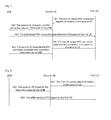
- Fig. 2 is a flowchart of a network access method for MTC in LTE-A according to an embodiment of the disclosure, including the following steps as shown in Fig. 2 .
- Step 201 to Step 203 include that first UE sends an RAP signal to second UE, the second UE forwards the RAP signal to an eNB, and the eNB sends an RAR signal to the first UE.
- the method may further include that the eNB broadcasts control signaling to release various information of an access network to each UE in a range of an area.
- Step 204 to Step 206 include that the first UE sends message signals of a DLL and an NL to the second UE.
- the second UE forwards the message signals of the DLL and the NL to the eNB.
- the eNB sends a competition parsing message to the first eNB to complete the network access.
- the message signals of the DLL and the NL are DLL and NL information related to network access, specifically including RRC connection request information, tracking area update information, and scheduling request information and so on.
- Fig. 3 is a flowchart of a method for establishing a network connection for MTC in LTE-A according to an embodiment of the disclosure, including the following steps as shown in Fig. 3 .
- Step 301 to Step 302 include that first UE sends RRC connection request information to second UE, and the second UE forwards to an eNB the RRC connection request information after receiving the RRC connection request information from the first UE.
- the second UE may select a connection request of the first UE, e.g. a plurality of pieces of first UE may initiate connection requests to the second UE in a cluster unit, and the second UE may select connection requests in order according to delays, process the one having shortest delay firstly, and so on.
- Step 303 includes that the eNB sends RRC connection establishment information to the first UE.
- the eNB may send sub-frame resource configuration information to the first UE through the RRC connection establishment information.
- the sub-frame resource configuration information includes sub-frame resource configuration information of a time domain and sub-frame resource configuration information of a frequency domain, wherein the sub-frame resource configuration information of the time domain is sent by the eNB to the second UE and the first UE in the cluster unit directly through SubframeConfig signaling in the RRC connection establishment information.
- the sub-frame resource configuration information of the frequency domain is sent by the eNB to the second UE and the first UE in the cluster unit through UCI in a PUCCH in an uplink direction, and is sent to the second UE and the first UE in the cluster unit by the eNB through DCI in a PDCCH in a downlink direction.
- the eNB is responsible for sub-frame resource configuration for MTC, including three links in the technical solutions of the disclosure.
- the eNB sends sub-frame resource configuration to the first UE and the second UE.
- the first UE sends sub-frame resource configuration information to the second UE
- the second UE sends the sub-frame resource configuration information to the eNB, wherein the sub-frame resource configuration information sent by the second UE to the eNB in the downlink direction and the uplink direction belongs to the prior art, and will not be described repeatedly here.
- a sub-band or a sub-frame is separately allocated to a resource allocated among second UE by the first UE in the uplink direction, thus avoiding interference caused by communication between the first UE and the second UE on other users.
- Table 1 is a frequency division resource allocation table in a Frequency Division Duplexing (FDD) system.
- FDD Frequency Division Duplexing
- Two independent channels are defined during an operation in the frequency division system, one of which is configured to transfer downlink information and the other one is configured to transfer uplink information, wherein F1 is a downlink frequency band, F2 is an uplink frequency band between second UE and an eNB, F3 is an MTC frequency band between first UE and the second UE, and the bandwidth of F2 is larger than that of F3.
- Table 1 F1 (downlink frequency band) eNB ⁇ first UE/second UE
- Second UE ⁇ eNB F3 MTC frequency band)
- Table 2 is a time division resource configuration table in an FDD system.
- time slots T1 and T2 are defined in an uplink frequency band and a downlink frequency band, wherein the time slots T1 and T2 of the downlink frequency band F1 are downlink frequency bands.
- the time slot T1 of the uplink frequency band F2 is divided into MTC sub-frames between first UE and second UE, and the time slot T2 of the uplink frequency band F2 is divided into sub-frames between the second UE and an eNB.
- Table 2 T1 (MTC sub-frame) T2 (LTE-A sub-frame) F1 (downlink frequency band) eNB ⁇ first UE/second UE F2 (uplink frequency band) First UE ⁇ second UE Second UE ⁇ eNB
- Table 3 is a frequency division resource configuration table in a Time Division Duplexing (TDD) system. Uplink data and downlink data are in different time slots of channels of the same frequency during an operation of the time division system. In this way, a time slot T1 and a time slot T2 are defined in frequency bands F1 and F2 in resource configuration as shown in Table 3.
- the time slot T1 is a downlink frequency band of the system
- the time slot T2 is an uplink frequency band between a second UE and an eNB.
- the time slot T1 is also a downlink frequency band of the system
- the time slot T2 is an uplink sub-frame between a first UE and the second UE.
- Table 3 T1 downlink Sub-frame T2 uplink sub-frame F1 eNB ⁇ first UE/second UE Second UE ⁇ eNB F2 First UE ⁇ second UE
- Table 4 is a time division resource configuration table in a TDD system, wherein a frequency channel is divided into three time slots in the resource configuration, i.e. time slots T1, T2 and T3, wherein the time slot T1 is a downlink sub-frame of the system, the time slot T2 is an uplink sub-frame between second UE and an eNB and the time slot T3 is an MTC uplink sub-frame between first UE and the second UE.
- Table 4 T1 (downlink sub-frame) T2 (uplink sub-frame) T3 (MTC sub-frame) eNB ⁇ first UE/second UE Second UE ⁇ eNB First UE ⁇ second UE
- Step 304 to Step 305 include that the first UE sends RRC connection establishment completion information to the second UE, and the second UE forwards the RRC connection establishment completion information to the eNB after receiving the RRC connection establishment completion information sent by the first UE.
- Fig. 4 is a flowchart of a method for data transmission for MTC in LTE-A according to an embodiment of the disclosure, including the following steps as shown in Fig. 4 .
- Step 401 to Step 402 include that first UE sends data information to second UE, and the second UE forwards the data information to an eNB after receiving the data information sent by the first UE.
- the first UE sends the data information to the second UE through a PUSCH, and the second UE forwards the data information to the eNB after receiving the data information sent by the first UE.
- Step 403 includes that the eNB sends a DTG signal to the first UE to complete the data transmission.
- the DTG signal includes Positive Acknowledgement (PACK) and Negative Acknowledgement (NACK).
- PACK Positive Acknowledgement
- NACK Negative Acknowledgement
- pieces of MTC UE are divided into a plurality of cluster units, each of which includes one piece of second UE as a cluster head and at least one piece of first UE as cluster members; data information sent by the first UE to an eNB is forwarded by the second UE having a relay function, thus improving the utilization rate of resources when there are limited frequency spectrum resources and reducing the burden of a base station.
- the number of pieces of first UE is far larger than that of second UE in each cluster unit.
- a cluster member can have short-distance communication with a cluster head, which means that the range of the base station is extended to some degree.
- first UE which is designed to have the minimalist functions of an existing MTC UE, has small transmission power, thus reducing interference to users around.
Landscapes
- Engineering & Computer Science (AREA)
- Computer Networks & Wireless Communication (AREA)
- Signal Processing (AREA)
- Mobile Radio Communication Systems (AREA)
Abstract
Description
- The disclosure relates to a Machine Type Communication (MTC) technology in the field of wireless communications, particularly to a method, system and device for MTC in Long Term Evolution Advanced (LTE-A).
- MTC refers to transferring information through communication networks so as to implement machine-to-machine data transmission. That is, interconnection and interworking between machines are implemented through the communication networks. A mobile communication network, which is able to provide mobility support without a necessity of setting up a network at a terminal side manually, is beneficial for saving cost and is able to satisfy communication requirements in a dangerous environment, thus an MTC service carried on the mobile communication network has gained wide attention. A mobile operator needs to improve the operating efficiency as much as possible when there are limited frequency spectrum resources and to control the number of Radio Access Technology (RAT) devices effectively in order to reduce the operating cost of the whole network. Nevertheless, MTC has a market that keeps growing rapidly, which means the number of terminals will increase.
- In the prior art, a base station needs to implement data transmission with each User Equipment (UE), and the burden of the base station will become increasingly heavy when the number of terminals is increased.
- In view of this, embodiments of the disclosure provide a method, system and device for MTC in LTE-A so as to improve the utilization rate of resources when there are limited frequency spectrum resources and to reduce the burden of a base station.
- To achieve the purpose, technical solutions of the embodiments of the disclosure is implemented by the following way.
- An embodiment of the disclosure provides a method for MTC in LTE-A. The method includes that pieces of MTC UE are divided into at least one cluster unit, each cluster unit includes one piece of second UE serving as a cluster head and at least one piece of first UE serving as cluster members, wherein
the first UE sends data information to the second UE through a Physical Uplink Shared Channel (PUSCH); after receiving the data information, the second UE forwards the data information to an Evolved Node B (eNB); the eNB sends Data Transmission Grant (DTG) information to the first UE after receiving the data information to complete data information transmission. - Preferably, before the first UE sends the data information to the second UE through the PUSCH, the method may further include that:
- the second UE forwards, to the eNB, Radio Resource Control (RRC) connection request information sent by the first UE to request for establishment of a network connection; the eNB sends RRC connection establishment information to the first UE; the first UE forwards RRC connection establishment completion information to the eNB through the second UE to complete the establishment of the network connection.
- Preferably, before the second UE forwards to the eNB, the RRC connection request information sent by the first UE to request for the establishment of the network connection, the method may further include that:
- the second UE forwards to the eNB a Random Access Preamble (RAP) signal sent by the first UE, so as to request for network access; the eNB sends a Random Access Response (RAR) signal to the first UE; the second UE forwards, to the eNB, message signals of a Data Link Layer (DLL) and a Network Layer (NL) from the first UE; and the eNB sends a competition parsing message to the first UE to complete the network access.
- Preferably, the method may further include that the eNB sends sub-frame resource configuration information to the second UE and the first UE through the RRC connection establishment information, wherein the sub-frame resource configuration information includes sub-frame resource configuration information of a time domain and sub-frame resource configuration information of a frequency domain.
- Preferably, the method may further include that the sub-frame resource configuration information of the time domain is sent to the second UE and the first UE by the eNB directly through SubframeConfig signaling in the RRC connection establishment information; and
the sub-frame resource configuration information of the frequency domain is sent to the second UE and the first UE by the eNB through Uplink Control Information (UCI) in a Physical Uplink Control Channel (PUCCH) in an uplink direction, and is sent to the second UE and the first UE by the eNB through Downlink Control Information (DCI) in a Physical Downlink Control Channel (PDCCH) in a downlink direction. - An embodiment of the disclosure further provides a cluster unit for MCT in LTE-A. The cluster unit includes one piece of second UE and at least one piece of first UE, wherein
the second UE may be configured to forward, to an eNB, data information sent by a first UE; and
the first UE may be configured to send the data information to the second UE through a PUSCH, and is further configured to receive DTG information sent by the eNB to complete data information transmission. - Preferably, the second UE may be configured to forward to the eNB RRC connection request information sent by the first UE, and is further configured to forward to the eNB RRC connection establishment completion information sent by the first UE to complete establishment of a network connection; and
the first UE may be configured to send the RRC connection request information to the second UE to request for the establishment of the network connection, and may be further configured to send the RRC connection establishment completion information to the second UE after receiving RRC connection establishment information sent by the eNB. - Preferably, the second UE may be configured to forward to the eNB an RAP signal sent by the first UE, and may be further configured to forward to the eNB message signals of a DLL and an NL from the first UE; and
the first UE may be configured to send the RAP signal to the second UE to request for network access and receive an RAR signal sent by the eNB, and may be further configured to send the message signals of the DLL and the NL to the second UE, and receive a competition parsing message sent by the eNB to complete the network access. - An embodiment of the disclosure further provides a system for MTC in LTE-A. The system includes an eNB and at least one cluster unit; each cluster unit includes one piece of second UE serving as a cluster head and at least one piece of first UE serving as cluster members, wherein
the eNB may be configured to send DTG information to the first UE after receiving data information from the second UE in the cluster unit, so as to complete data information transmission; and
the cluster unit may be configured to forward the data information sent by the first UE to the eNB through the second UE. - Preferably, the eNB may be configured to send RRC connection establishment information to the first UE in the cluster unit after receiving RRC connection request information from the second UE in the cluster unit, and may be further configured to receive RRC connection establishment completion information from the second UE in the cluster unit so as to complete establishment of a network connection; and
the cluster unit may be configured to send through the second UE the RRC connection request information to the eNB so as to request for the establishment of the network connection, and may be further configured to forward through the second UE the RRC connection establishment completion information sent by the first UE to the eNB after receiving the RRC connection establishment information from the eNB. - Preferably, the eNB may be further configured to send an RAR signal to the first UE in the cluster unit after receiving a RAP signal from the second UE in the cluster unit, and may be further configured to send a competition parsing message to the first UE in the cluster unit after receiving message signals of a DLL and an NL from the second UE in the cluster unit, so as to complete network access; and
the cluster unit may be further configured to forward through the second UE the RAP signal sent by the first UE to the eNB, so as to request for the network access, and may be further configured to forward to the eNB through the second UE the message signals of the DLL and the NL sent by the first UE. - Preferably, the second UE may be configured to forward to the eNB the data information sent by the first UE; and
the first UE may be configured to send the data information to the second UE through a PUSCH, and may be further configured to receive the DTG information from the eNB so as to complete the data information transmission. - Preferably, the second UE may be configured to forward to the eNB the RRC connection request information sent by the first UE, and may be further configured to forward to the eNB the RRC connection establishment completion information sent by the first UE so as to complete the establishment of the network connection; and
the first UE may be configured to send the RRC connection request information to the second UE to request for the establishment of the network connection, and may be further configured to send the RRC connection establishment completion information to the second UE after receiving the RRC connection establishment information sent by the eNB. - Preferably, the second UE may be configured to forward to the eNB the RAP signal sent by the first UE, and may be further configured to forward to the eNB the message signals of the DLL and the NL from the first UE; and
the first UE may be configured to send the RAP signal to the second UE to request for the network access and receive the RAR signal sent by the eNB, and may be further configured to send the second UE the message signals of DLL and NL sent by the second UE and to receive the competition parsing message sent by the eNB so as to complete the network access. - Preferably, the eNB may be further configured to send sub-frame resource configuration information to the cluster unit through the RRC connection establishment information, wherein the sub-frame resource configuration information includes sub-frame resource configuration information of a time domain and sub-frame resource configuration information of a frequency domain.
- Preferably, the sub-frame resource configuration information of the time domain may be sent to the second UE and the first UE in the cluster unit by the eNB directly through SubframeConfig signaling in the RRC connection establishment information;
the sub-frame resource configuration information of the frequency domain may be sent to the second UE and the first UE in the cluster unit by the eNB through UCI in a PUCCH in an uplink direction, and may be sent to the second UE and the first UE in the cluster unit by the eNB through DCI in a PDCCH in a downlink direction. - The method, system and device for MTC in LTE-A according to the embodiments of the disclosure divide pieces of MTC UE into at least one cluster unit, each of which includes one piece of second UE serving as a cluster head and at least one piece of first UE serving as cluster members; the first UE sends data information to the second UE through a PUSCH; after receiving the data information, the second UE forwards the data information to an eNB; after receiving the data information, the eNB sends DTG information to the first UE so as to complete data information transmission. It can be seen that the data information sent by the first UE to the eNB is forwarded by the second UE having a relay function in an uplink direction according to the embodiments of the disclosure, thus improving the utilization rate of resources when frequency spectrum resources are limited and reducing the burden of a base station. In addition, the number of pieced of first UE is far larger than that of second UE in each cluster unit. In uplink transmission, a cluster member can have short-distance communication with a cluster head, which means that the range of the base station is extended to some degree. Besides, first UE, which is designed to have the minimalist functions of existing MTC UE, has small transmission power, thus reducing interference to users around.
-
-
Fig. 1 is a schematic diagram of a composition architecture of a system for MTC in LTE-A according to an embodiment of the disclosure; -
Fig. 2 is a flowchart of a network access method for MTC in LTE-A according to an embodiment of the disclosure; -
Fig. 3 is a flowchart of a method for establishing a network connection for MTC in LTE-A according to an embodiment of the disclosure; and -
Fig. 4 is a flowchart of a method for data transmission for MTC in LTE-A according to an embodiment of the disclosure. - The disclosure will be further expounded below in combination with the accompanying drawings and specific embodiments.
-
Fig. 1 is a schematic diagram of a composition architecture of a system supporting MTC in LTE-A according to an embodiment of the disclosure. As shown inFig. 1 , the system includes an eNB 11 andcluster units 12, each of thecluster units 12 includes one piece of second UE serving as a cluster head and at least one piece of first UE serving as cluster members, wherein
the eNB 11 is configured to, after receiving data information from acluster unit 12, send DTG information to the first UE which sends the data information in thecluster unit 12 so as to complete data information transmission; and
thecluster unit 12 is configured to send through the second UE the data information to the eNB 11. - Here, the MTC UE may be divided into a plurality of cluster units.
- Preferably, the eNB 11 is further configured to send RRC connection establishment information to the first UE in the
cluster unit 12 after receiving RRC connection request information sent by the second UE in thecluster unit 12, and is further configured to receive RRC connection establishment completion information sent by the second UE in thecluster unit 12 so as to complete establishment of a network connection; and
thecluster unit 12 is configured to send through the second UE the RRC connection request information to theeNB 11 so as to request for the establishment of the network connection, and is further configured to forward through the second UE the RRC connection establishment completion information sent by the first UE to theeNB 11 after receiving the RRC connection establishment information from theeNB 11. - Preferably, the
eNB 11 is further configured to send an RAR signal to the first UE in thecluster unit 12 after receiving an RAP signal from the second UE in thecluster unit 12, and is further configured to send a competition parsing message to the first UE in thecluster unit 12 after receiving message signals of a DLL and an NL from the second UE in thecluster unit 12, so as to complete network access; and
thecluster unit 12 is further configured to forward through the second UE the RAP signal sent by the first UE to theeNB 11, so as to request for the network access, and is further configured to forward through the second UE the message signals of the DLL and the NL sent by the first UE to theeNB 11. - Preferably, the
eNB 11 is further configured to send sub-frame resource configuration information to the first UE and the second UE in thecluster unit 12 through the RRC connection establishment information, wherein the sub-frame resource configuration information includes sub-frame resource configuration information of a time domain and sub-frame resource configuration information of a frequency domain. - Here, the sub-frame resource configuration information of the time domain is sent to the second UE and the first UE in the
cluster unit 12 by theeNB 11 directly through SubframeConfig signaling in the RRC connection establishment information;
the sub-frame resource configuration information of the frequency domain is sent to the second UE and the first UE in thecluster unit 12 by theeNB 11 through UCI in a PUCCH in an uplink direction, and is sent to the second UE and the first UE in thecluster unit 12 by theeNB 11 through DCI in a PDCCH in a downlink direction. - Preferably, the
cluster unit 12 includessecond UE 121 andfirst UE 122, wherein
thesecond UE 121 is configured to forward, to theeNB 11, data information sent by thefirst UE 122;
thefirst UE 122 is configured to send the data information through a PUSCH to thesecond UE 121, and is further configured to receive DTG information sent by theeNB 11 so as to complete data information transmission. - Preferably, the
second UE 121 is configured to forward to theeNB 11 RRC connection request information sent by thefirst UE 122, and is further configured to forward to theeNB 11 RRC connection establishment completion information sent by thefirst UE 122 so as to complete establishment of a network connection; - Correspondingly, the
first UE 122 is further configured to send the RRC connection request information to thesecond UE 121 to request for the establishment of the network connection; and is further configured to send the RRC connection establishment completion information to thesecond UE 121 after receiving RRC connection establishment information sent by theeNB 11. - Preferably, the
second UE 121 is further configured to forward to theeNB 11 an RAP signal sent by thefirst UE 122, and is further configured to forward to theeNB 11 message signals of a DLL and an NL from thefirst UE 122. - Correspondingly, the
first UE 122 is configured to send the RAP signal to thesecond UE 121 to request for network access and receive an RAR signal sent by theeNB 11, and is further configured to send the message signals of the DLL and the NL to thesecond UE 121, and receive a competition parsing message sent by theeNB 11 so as to complete the network access. - Specifically, the
eNB 11 broadcasts control signaling to release various information of an access network. After receiving the control signaling,first UE 122 sends an RAP signal. Ifsecond UE 121 receives the RAP signal, thesecond UE 121 forwards the RAP signal to theeNB 11. If there is nosecond UE 121 receiving the RAP signal, thefirst UE 122 sends the RAP signal to theeNB 11 directly. A process described herein and hereinafter for thefirst UE 122 to perform uplink communication directly with and theeNB 11 belong to the prior art, and will not be described repeatedly in the disclosure. After receiving the RAP signal forwarded by thesecond UE 121, theeNB 11 sends an RAR signal to thefirst UE 122. Thefirst UE 122 sends message signals of a DLL and an NL to thesecond UE 121. Thesecond UE 121 forwards the message signals of the DLL and the NL to theeNB 11. TheeNB 11 sends a competition parsing message to thefirst UE 122 to complete network access. - The
first UE 122 sends RRC connection request information. After receiving the RRC connection request information from thefirst UE 122, thesecond UE 121 forwards the information to theeNB 11. TheeNB 11 sends RRC connection establishment information to thefirst UE 122, and thefirst UE 122 forwards RRC connection establishment completion message to theeNB 11 through thesecond UE 121 so as to complete the establishment of the network connection. - The
first UE 122 forwards the data information to theeNB 11 through thesecond UE 121. After receiving the data information, theeNB 11 sends the DTG information to thefirst UE 122 so as to complete the data information transmission. - Here, the first UE is provided with a common function of an existing MTC UE. In terms of the design of a bottom layer, a radio frequency part, which adopts an LTE/LTE-A frequency band, is applicable to an LTE/LTE-A system, and a single transceiver antenna and a single radio frequency link are applied. In an aspect of protocols and progresses, protocols of a Media Access Control (MAC) layer and a Radio Link Control (RLC) layer, as well as a progress at a physical layer are simplified. In an aspect of baseband, a standard that MTC UE has the minimalist functions in an LTE/LTE-A system and a lower order Modulation Coding Scheme (MCS) are applied and a Hybrid Automatic Repeat Request (HARQ) progress is deleted, and so on, thus reducing a data rate, reducing transmission efficiency, lowering power consumption and reducing interference to users around.
- The second UE, which is added with a relay function compared with existing MTC UE, also applies an LTE/LTE-A frequency band so that the second UE can forward uplink data of the first UE to the eNB.
-
Fig. 2 is a flowchart of a network access method for MTC in LTE-A according to an embodiment of the disclosure, including the following steps as shown inFig. 2 . - Step 201 to Step 203 include that first UE sends an RAP signal to second UE, the second UE forwards the RAP signal to an eNB, and the eNB sends an RAR signal to the first UE.
- Here, before the first UE sends the RAP signal to the second UE, the method may further include that the eNB broadcasts control signaling to release various information of an access network to each UE in a range of an area.
- Step 204 to Step 206 include that the first UE sends message signals of a DLL and an NL to the second UE. The second UE forwards the message signals of the DLL and the NL to the eNB. The eNB sends a competition parsing message to the first eNB to complete the network access.
- Here, the message signals of the DLL and the NL are DLL and NL information related to network access, specifically including RRC connection request information, tracking area update information, and scheduling request information and so on.
-
Fig. 3 is a flowchart of a method for establishing a network connection for MTC in LTE-A according to an embodiment of the disclosure, including the following steps as shown inFig. 3 . - Step 301 to Step 302 include that first UE sends RRC connection request information to second UE, and the second UE forwards to an eNB the RRC connection request information after receiving the RRC connection request information from the first UE.
- Here, the second UE may select a connection request of the first UE, e.g. a plurality of pieces of first UE may initiate connection requests to the second UE in a cluster unit, and the second UE may select connection requests in order according to delays, process the one having shortest delay firstly, and so on.
- Step 303 includes that the eNB sends RRC connection establishment information to the first UE.
- Here, the eNB may send sub-frame resource configuration information to the first UE through the RRC connection establishment information. The sub-frame resource configuration information includes sub-frame resource configuration information of a time domain and sub-frame resource configuration information of a frequency domain,
wherein the sub-frame resource configuration information of the time domain is sent by the eNB to the second UE and the first UE in the cluster unit directly through SubframeConfig signaling in the RRC connection establishment information. - The sub-frame resource configuration information of the frequency domain is sent by the eNB to the second UE and the first UE in the cluster unit through UCI in a PUCCH in an uplink direction, and is sent to the second UE and the first UE in the cluster unit by the eNB through DCI in a PDCCH in a downlink direction.
- Specifically, the eNB is responsible for sub-frame resource configuration for MTC, including three links in the technical solutions of the disclosure. In a downlink direction, the eNB sends sub-frame resource configuration to the first UE and the second UE. In an uplink direction, the first UE sends sub-frame resource configuration information to the second UE, and the second UE sends the sub-frame resource configuration information to the eNB, wherein the sub-frame resource configuration information sent by the second UE to the eNB in the downlink direction and the uplink direction belongs to the prior art, and will not be described repeatedly here. A sub-band or a sub-frame is separately allocated to a resource allocated among second UE by the first UE in the uplink direction, thus avoiding interference caused by communication between the first UE and the second UE on other users.
- Specifically, there may be four cases of resource configuration in the system according to the embodiment of the disclosure, as shown in Table 1 to Table 4, wherein Table 1 is a frequency division resource allocation table in a Frequency Division Duplexing (FDD) system. Two independent channels are defined during an operation in the frequency division system, one of which is configured to transfer downlink information and the other one is configured to transfer uplink information, wherein F1 is a downlink frequency band, F2 is an uplink frequency band between second UE and an eNB, F3 is an MTC frequency band between first UE and the second UE, and the bandwidth of F2 is larger than that of F3.
Table 1 F1 (downlink frequency band) eNB→first UE/second UE F2 (uplink frequency band) Second UE→eNB F3 (MTC frequency band) First UE→second UE - Table 2 is a time division resource configuration table in an FDD system. In the resource configuration, time slots T1 and T2 are defined in an uplink frequency band and a downlink frequency band, wherein the time slots T1 and T2 of the downlink frequency band F1 are downlink frequency bands. The time slot T1 of the uplink frequency band F2 is divided into MTC sub-frames between first UE and second UE, and the time slot T2 of the uplink frequency band F2 is divided into sub-frames between the second UE and an eNB.
Table 2 T1 (MTC sub-frame) T2 (LTE-A sub-frame) F1 (downlink frequency band) eNB→first UE/second UE F2 (uplink frequency band) First UE→second UE Second UE→eNB - Table 3 is a frequency division resource configuration table in a Time Division Duplexing (TDD) system. Uplink data and downlink data are in different time slots of channels of the same frequency during an operation of the time division system. In this way, a time slot T1 and a time slot T2 are defined in frequency bands F1 and F2 in resource configuration as shown in Table 3. In the frequency band F1, the time slot T1 is a downlink frequency band of the system, and the time slot T2 is an uplink frequency band between a second UE and an eNB. In the frequency band F2, the time slot T1 is also a downlink frequency band of the system, and the time slot T2 is an uplink sub-frame between a first UE and the second UE.
Table 3 T1 downlink Sub-frame T2 uplink sub-frame F1 eNB→first UE/second UE Second UE→eNB F2 First UE→second UE - Table 4 is a time division resource configuration table in a TDD system, wherein a frequency channel is divided into three time slots in the resource configuration, i.e. time slots T1, T2 and T3, wherein the time slot T1 is a downlink sub-frame of the system, the time slot T2 is an uplink sub-frame between second UE and an eNB and the time slot T3 is an MTC uplink sub-frame between first UE and the second UE.
Table 4 T1 (downlink sub-frame) T2 (uplink sub-frame) T3 (MTC sub-frame) eNB→first UE/second UE Second UE→eNB First UE→second UE - Step 304 to Step 305 include that the first UE sends RRC connection establishment completion information to the second UE, and the second UE forwards the RRC connection establishment completion information to the eNB after receiving the RRC connection establishment completion information sent by the first UE.
-
Fig. 4 is a flowchart of a method for data transmission for MTC in LTE-A according to an embodiment of the disclosure, including the following steps as shown inFig. 4 . - Step 401 to Step 402 include that first UE sends data information to second UE, and the second UE forwards the data information to an eNB after receiving the data information sent by the first UE.
- Here, the first UE sends the data information to the second UE through a PUSCH, and the second UE forwards the data information to the eNB after receiving the data information sent by the first UE.
- Step 403 includes that the eNB sends a DTG signal to the first UE to complete the data transmission.
- Here, the DTG signal includes Positive Acknowledgement (PACK) and Negative Acknowledgement (NACK). When the first UE receives the PACK, it indicates that data has been received inerrably. When the first UE receives the NACK, it indicates that data has been received mistakenly, and data needs to be retransmitted, then the first UE performs
Step 401 again to continue to transmit data information. - The foregoing descriptions are only preferred embodiments of the disclosure and are not used for limiting the protection scope of the disclosure. All modifications, equivalent replacements and improvements and the like made within the spirit and scope of the disclosure shall be included within the protection scope of the disclosure.
- In the embodiments of the disclosure, pieces of MTC UE are divided into a plurality of cluster units, each of which includes one piece of second UE as a cluster head and at least one piece of first UE as cluster members; data information sent by the first UE to an eNB is forwarded by the second UE having a relay function, thus improving the utilization rate of resources when there are limited frequency spectrum resources and reducing the burden of a base station. In addition, the number of pieces of first UE is far larger than that of second UE in each cluster unit. In uplink transmission, a cluster member can have short-distance communication with a cluster head, which means that the range of the base station is extended to some degree. Besides, first UE, which is designed to have the minimalist functions of an existing MTC UE, has small transmission power, thus reducing interference to users around.
Claims (16)
- A method for Machine Type Communication (MTC) in Long Term Evolution Advanced (LTE-A), comprising: dividing pieces of MTC User Equipment (UE) into at least one cluster unit, each cluster unit comprising one piece of second UE serving as a cluster head and at least one pieces of first UE serving as cluster members, wherein
the first UE sends data information to the second UE through a Physical Uplink Shared Channel (PUSCH); after receiving the data information the second UE forwards the data information to an Evolved Node B (eNB); the eNB sends Data Transmission Grant (DTG) information to the first UE after receiving the data information to complete data information transmission. - The method according to claim 1, before the first UE sends the data information to the second UE through the PUSCH, the method further comprising:forwarding to the eNB, by the second UE, Radio Resource Control (RRC) connection request information sent by the first UE to request for establishment of a network connection;sending, by the eNB, RRC connection establishment information to the first UE; andforwarding, by the first UE, RRC connection establishment completion information to the eNB through the second UE to complete the establishment of the network connection.
- The method according to claim 2, before forwarding to the eNB, by the second UE, the RRC connection request information sent by the first UE to request for the establishment of the network connection, the method further comprising:forwarding to the eNB, by the second UE, a Random Access Preamble (RAP) signal sent by the first UE, so as to request for network access;sending, by the eNB, a Random Access Response (RAR) signal to the first UE;forwarding to the eNB, by the second UE, message signals of a Data Link Layer (DLL) and a Network Layer (NL) from the first UE; andsending, by the eNB, a competition parsing message to the first UE to complete the network access.
- The method according to claim 2, further comprising:sending, by the eNB, sub-frame resource configuration information to the second UE and the first UE through the RRC connection establishment information, wherein the sub-frame resource configuration information comprises sub-frame resource configuration information of a time domain and sub-frame resource configuration information of a frequency domain.
- The method according to claim 4, further comprising:sending, by the eNB, the sub-frame resource configuration information of the time domain to the second UE and the first UE directly through SubframeConfig signaling in the RRC connection establishment information;sending, by the eNB, the sub-frame resource configuration information of the frequency domain to the second UE and the first UE through Uplink Control Information (UCI) in a Physical Uplink Control Channel (PUCCH) in an uplink direction, and through Downlink Control Information (DCI) in a Physical Downlink Control Channel (PDCCH) in a downlink direction.
- A cluster unit for Machine Type Communication (MTC) in Long Term Evolution Advanced (LTE-A), comprising one piece of second User Equipment (UE) and at least one piece of first UE, wherein
the second UE is configured to forward to an Evolved Node B (eNB) data information sent by the first UE; and
the first UE is configured to send the data information to the second UE through a Physical Uplink Shared Channel (PUSCH), and is further configured to receive Data Transmission Grant (DTG) information sent by the eNB to complete data information transmission. - The cluster unit according to claim 6, wherein
the second UE is configured to forward to the eNB Radio Resource Control (RRC) connection request information sent by the first UE, and is further configured to forward to the eNB RRC connection establishment completion information sent by the first UE to complete establishment of a network connection; and
the first UE is configured to send the RRC connection request information to the second UE to request for the establishment of the network connection, and is further configured to send the RRC connection establishment completion information to the second UE after receiving RRC connection establishment information sent by the eNB. - The cluster unit according to claim 6, wherein
the second UE is configured to forward to the eNB a Random Access Preamble (RAP) signal sent by the first UE, and is further configured to forward to the eNB message signals of a Data Link Layer (DLL) and a Network Layer (NL) from the first UE; and
the first UE is configured to send the RAP signal to the second UE to request for network access and receive a Random Access Response (RAR) signal from the eNB, and is further configured to send the message signals of the DLL and the NL to the second UE, and receive a competition parsing message from the eNB so as to complete the network access. - A system for Machine Type Communication (MTC) in Long Term Evolution Advanced (LTE-A), comprising an Evolved Node B (eNB) and at least one cluster unit; each cluster unit comprises one piece of second User Equipment (UE) serving as a cluster head and at least one piece of first UE serving as cluster members, wherein
the eNB is configured to send Data Transmission Grant (DTG) information to the first UE after receiving data information from the second UE in the cluster unit, to complete data information transmission; and
the cluster unit is configured to forward the data information sent by the first UE to the eNB through the second UE. - The system according to claim 9, wherein
the eNB is configured to send Radio Resource Control (RRC) connection establishment information to the first UE in the cluster unit after receiving RRC connection request information from the second UE in the cluster unit, and is further configured to receive RRC connection establishment completion information from the second UE in the cluster unit to complete establishment of a network connection; and
the cluster unit is configured to send through the second UE the RRC connection request information to the eNB to request for the establishment of the network connection, and is further configured to forward through the second UE the RRC connection establishment completion information sent by the first UE to the eNB after receiving the RRC connection establishment information from the eNB. - The system according to claim 10, wherein
the eNB is further configured to send an Random Access Response (RAR) signal to the first UE in the cluster unit after receiving a Random Access Preamble (RAP) signal from the second UE in the cluster unit, and is further configured to send a competition parsing message to the first UE in the cluster unit after receiving message signals of a Data Link Layer (DLL) and a Network Layer (NL) from the second UE in the cluster unit, to complete network access; and
the cluster unit is further configured to forward through the second UE the RAP signal sent by the first UE to the eNB, so as to request for the network access, and is further configured to forward to the eNB through the second UE the message signals of the DLL and the NL sent by the first UE. - The system according to claim 9, 10 or 11, wherein
the second UE is configured to forward to the eNB the data information sent by the first UE; and
the first UE is configured to send the data information to the second UE through a Physical Uplink Shared Channel (PUSCH), and is further configured to receive the DTG information from the eNB to complete the data information transmission. - The system according to claim 12, wherein
the second UE is configured to forward to the eNB the RRC connection request information sent by the first UE, and is further configured to forward to the eNB the RRC connection establishment completion information sent by the first UE to complete the establishment of the network connection; and
the first UE is configured to send the RRC connection request information to the second UE to request for the establishment of the network connection, and is further configured to send the RRC connection establishment completion information to the second UE after receiving the RRC connection establishment information from the eNB. - The system according to claim 13, wherein
the second UE is configured to forward to the eNB the RAP signal sent by the first UE, and is further configured to forward to the eNB the message signals of the DLL and the NL from the first UE;
the first UE is configured to send the RAP signal to the second UE to request for the network access and receive the RAR signal from the eNB, and is further configured to send to the second UE the message signals of the DLL and NL sent by the second UE and receive the competition parsing message from the eNB to complete the network access. - The system according to claim 11, wherein the eNB is further configured to send sub-frame resource configuration information to the cluster unit through the RRC connection establishment information, wherein the sub-frame resource configuration information comprises sub-frame resource configuration of a time domain and sub-frame resource configuration information of a frequency domain.
- The system according to claim 15, wherein
the sub-frame resource configuration information of the time domain is sent to the second UE and the first UE in the cluster unit by the eNB directly through SubframeConfig signaling in the RRC connection establishment information; and
the sub-frame resource configuration information of the frequency domain is sent to the second UE and the first UE in the cluster unit by the eNB through Uplink Control Information (UCI) in a Physical Uplink Control Channel (PUCCH) in an uplink direction, and is sent to the second UE and the first UE in the cluster unit by the eNB through Downlink Control Information (DCI) in a Physical Downlink Control Channel (PDCCH) in a downlink direction.
Applications Claiming Priority (2)
| Application Number | Priority Date | Filing Date | Title |
|---|---|---|---|
| CN201210428068.0A CN103796312B (en) | 2012-10-31 | 2012-10-31 | The method of machine type communication, system and equipment in LTE A |
| PCT/CN2013/084027 WO2014067369A1 (en) | 2012-10-31 | 2013-09-23 | Method, system and device for machine type communication in lte-a |
Publications (2)
| Publication Number | Publication Date |
|---|---|
| EP2916615A1 true EP2916615A1 (en) | 2015-09-09 |
| EP2916615A4 EP2916615A4 (en) | 2015-12-30 |
Family
ID=50626449
Family Applications (1)
| Application Number | Title | Priority Date | Filing Date |
|---|---|---|---|
| EP13851126.6A Withdrawn EP2916615A4 (en) | 2012-10-31 | 2013-09-23 | METHOD, SYSTEM AND DEVICE FOR MACHINE TYPE COMMUNICATION BY LTE-A TECHNOLOGY |
Country Status (4)
| Country | Link |
|---|---|
| US (1) | US9736620B2 (en) |
| EP (1) | EP2916615A4 (en) |
| CN (1) | CN103796312B (en) |
| WO (1) | WO2014067369A1 (en) |
Families Citing this family (16)
| Publication number | Priority date | Publication date | Assignee | Title |
|---|---|---|---|---|
| EP2986051B1 (en) * | 2013-04-08 | 2018-05-30 | LG Electronics Inc. | Group membership assessment for a proximity-based service in wireless communication system |
| WO2015156643A1 (en) * | 2014-04-10 | 2015-10-15 | Samsung Electronics Co., Ltd. | Method and system for providing data communication through a cluster head for machine type communication (mtc) based group communication |
| US9742848B2 (en) * | 2014-04-10 | 2017-08-22 | Samsung Electronics Co., Ltd | Method and system for transmitting paging messages to machine type communication (MTC) devices in wireless communication |
| US9820247B2 (en) * | 2014-07-30 | 2017-11-14 | Intel IP Corporation | Enhanced node B (ENB) and method for MTC coexistence |
| JP2018500840A (en) * | 2014-12-31 | 2018-01-11 | ホアウェイ・テクノロジーズ・カンパニー・リミテッド | COMMUNICATION METHOD, COMMUNICATION SYSTEM AND DEVICE |
| CN106793148B (en) | 2015-11-20 | 2021-11-30 | 中兴通讯股份有限公司 | Random access method and device |
| WO2017140349A1 (en) * | 2016-02-16 | 2017-08-24 | Telefonaktiebolaget Lm Ericsson (Publ) | Network access of a wireless device |
| CN107347177B (en) * | 2016-05-06 | 2020-03-24 | 电信科学技术研究院 | Data transmission method and device |
| CN107371118B (en) * | 2016-05-11 | 2020-09-08 | 华为技术有限公司 | A communication method and device |
| CN107770871B (en) * | 2016-08-22 | 2021-09-14 | 华为技术有限公司 | Message receiving and sending method, terminal equipment and network equipment |
| KR102746338B1 (en) | 2016-12-02 | 2024-12-26 | 삼성전자 주식회사 | Preamble signal detection method of communication system and apparatus for the same |
| US10057898B2 (en) * | 2016-12-21 | 2018-08-21 | Phazr, Inc. | Downlink and uplink data multiplexing on widely spaced frequencies in wireless broadband communication system |
| CN107222907A (en) * | 2017-05-10 | 2017-09-29 | 华中科技大学 | The cellular network transmission method of auxiliary is relayed based on up non-orthogonal multiple |
| CN114651498B (en) * | 2019-11-14 | 2026-02-03 | 高通股份有限公司 | Random access channel procedure with external assistance |
| WO2022036560A1 (en) | 2020-08-18 | 2022-02-24 | 华为技术有限公司 | Data transmission method and related device |
| CN115378472A (en) * | 2021-05-19 | 2022-11-22 | 北京小米移动软件有限公司 | Communication method, communication device, electronic device and storage medium |
Family Cites Families (11)
| Publication number | Priority date | Publication date | Assignee | Title |
|---|---|---|---|---|
| US8570956B2 (en) * | 2006-06-21 | 2013-10-29 | Lg Electronics Inc. | Method of communicating data in a wireless mobile communications system using message separation and mobile terminal for use with the same |
| JP5070093B2 (en) * | 2008-03-06 | 2012-11-07 | パナソニック株式会社 | Radio base station apparatus, radio terminal apparatus, radio relay station apparatus, transmission power control method, radio communication relay method, and radio communication system |
| CN101754410B (en) * | 2008-12-19 | 2012-09-05 | 华为技术有限公司 | Network access method and device |
| CN101730123A (en) | 2009-12-22 | 2010-06-09 | 中兴通讯股份有限公司 | M2M platform system, junction terminal and terminal control method |
| KR101477518B1 (en) * | 2010-01-06 | 2014-12-30 | 한국전자통신연구원 | Machine tyep communication system |
| WO2011136524A2 (en) * | 2010-04-25 | 2011-11-03 | 엘지전자 주식회사 | Method and apparatus for transceiving data in a wireless access system |
| WO2012106619A1 (en) * | 2011-02-03 | 2012-08-09 | Telcordia Technologies, Inc. | System and method for group communications in 3gpp machine-to-machine networks |
| CN102158901B (en) * | 2011-02-16 | 2014-01-08 | 大唐移动通信设备有限公司 | Method for performing terminal operation configuration at network side and network side device |
| CN102164425A (en) * | 2011-05-11 | 2011-08-24 | 大唐移动通信设备有限公司 | MTC (machine type communication)equipment management method, system and MTC equipment |
| GB2493781B (en) * | 2011-08-19 | 2016-07-27 | Nvidia Corp | Wireless communications system and method |
| US9578635B2 (en) * | 2012-09-28 | 2017-02-21 | Intel Corporation | Method and apparatus for autonomous cluster head selection for machine-type-communications (MTC) |
-
2012
- 2012-10-31 CN CN201210428068.0A patent/CN103796312B/en active Active
-
2013
- 2013-09-23 EP EP13851126.6A patent/EP2916615A4/en not_active Withdrawn
- 2013-09-23 US US14/439,932 patent/US9736620B2/en active Active
- 2013-09-23 WO PCT/CN2013/084027 patent/WO2014067369A1/en not_active Ceased
Also Published As
| Publication number | Publication date |
|---|---|
| WO2014067369A1 (en) | 2014-05-08 |
| EP2916615A4 (en) | 2015-12-30 |
| US9736620B2 (en) | 2017-08-15 |
| US20150289080A1 (en) | 2015-10-08 |
| CN103796312B (en) | 2017-06-27 |
| CN103796312A (en) | 2014-05-14 |
Similar Documents
| Publication | Publication Date | Title |
|---|---|---|
| US9736620B2 (en) | Method, system and device for machine type communication in LTE-A | |
| US12010561B2 (en) | Transmission of group handover message | |
| EP2901602B1 (en) | Transmission of uplink control information in inter-enb carrier aggregation | |
| EP2897428B1 (en) | Method of handling uplink synchronization and related communication device | |
| US9426788B2 (en) | Methods and apparatus for transmitting and/or controlling device-to-device discovery signals | |
| US9614652B2 (en) | Radio base stations and wireless terminal for dual connectivity, methods therein and a system | |
| EP3886528B1 (en) | Cell state management methods and apparatuses | |
| US10080223B2 (en) | Method for configuring transmission time interval bundling at a user equipment with multiple carriers and device therefor | |
| JP2015514346A (en) | Physical layer multipoint carrier aggregation setting and data transfer method | |
| US10051657B2 (en) | User terminal, radio base station and radio communication method | |
| CN102300301A (en) | Method of handling transmit power control and control signaling and related communication device | |
| KR20180003635A (en) | Methods, apparatus and systems for performing multi-radio access technology carrier aggregation | |
| US20220104208A1 (en) | Csi reporting method and terminal device | |
| EP3301874B1 (en) | Data transmission method and relevant device | |
| US20160174177A1 (en) | Timing advance methods and apparatuses | |
| KR20120114176A (en) | Method and appratus for atransmission a random access and other uplink channels in other serving cells in carrier aggregation in a wireless system | |
| US10356804B2 (en) | Data transmission method and user equipment | |
| CN106465298A (en) | User terminal, wireless base station, wireless communication system, and wireless communication method | |
| WO2015074269A1 (en) | Communication system, device and method | |
| US11658786B2 (en) | Configuration and procedure for search space used in small data transfer over pre-configured uplink resources | |
| JP2015192359A (en) | Wireless communication terminal, wireless base station, and wireless communication method | |
| JP2014236511A (en) | Method and communication device for tti bundling | |
| CN114303405A (en) | Transmission Configuration Indication (TCI) status/beam determination for NR Dual Active Protocol Stack (DAPS) handover | |
| US20260113624A1 (en) | Ue indication of multi-rx chain downlink reception capability | |
| JP2012213142A (en) | Method of controlling receive diversity for battery lifetime improvement and related communication device |
Legal Events
| Date | Code | Title | Description |
|---|---|---|---|
| PUAI | Public reference made under article 153(3) epc to a published international application that has entered the european phase |
Free format text: ORIGINAL CODE: 0009012 |
|
| 17P | Request for examination filed |
Effective date: 20150529 |
|
| AK | Designated contracting states |
Kind code of ref document: A1 Designated state(s): AL AT BE BG CH CY CZ DE DK EE ES FI FR GB GR HR HU IE IS IT LI LT LU LV MC MK MT NL NO PL PT RO RS SE SI SK SM TR |
|
| AX | Request for extension of the european patent |
Extension state: BA ME |
|
| RA4 | Supplementary search report drawn up and despatched (corrected) |
Effective date: 20151126 |
|
| RIC1 | Information provided on ipc code assigned before grant |
Ipc: H04W 4/00 20090101ALI20151120BHEP Ipc: H04W 88/04 20090101AFI20151120BHEP |
|
| DAX | Request for extension of the european patent (deleted) | ||
| RAP1 | Party data changed (applicant data changed or rights of an application transferred) |
Owner name: ZTE CORPORATION Owner name: ZTE MICROELECTRONICS TECHNOLOGY CO., LTD. |
|
| RAP1 | Party data changed (applicant data changed or rights of an application transferred) |
Owner name: SANECHIPS TECHNOLOGY CO., LTD. Owner name: ZTE CORPORATION |
|
| STAA | Information on the status of an ep patent application or granted ep patent |
Free format text: STATUS: EXAMINATION IS IN PROGRESS |
|
| 17Q | First examination report despatched |
Effective date: 20180716 |
|
| STAA | Information on the status of an ep patent application or granted ep patent |
Free format text: STATUS: THE APPLICATION IS DEEMED TO BE WITHDRAWN |
|
| 18D | Application deemed to be withdrawn |
Effective date: 20230607 |