EP2916510B1 - Network authentication method for secure user identity verification using user positioning information - Google Patents
Network authentication method for secure user identity verification using user positioning information Download PDFInfo
- Publication number
- EP2916510B1 EP2916510B1 EP14157510.0A EP14157510A EP2916510B1 EP 2916510 B1 EP2916510 B1 EP 2916510B1 EP 14157510 A EP14157510 A EP 14157510A EP 2916510 B1 EP2916510 B1 EP 2916510B1
- Authority
- EP
- European Patent Office
- Prior art keywords
- portable personal
- data
- user terminal
- electronic device
- positioning
- Prior art date
- Legal status (The legal status is an assumption and is not a legal conclusion. Google has not performed a legal analysis and makes no representation as to the accuracy of the status listed.)
- Active
Links
Images



Classifications
-
- H—ELECTRICITY
- H04—ELECTRIC COMMUNICATION TECHNIQUE
- H04L—TRANSMISSION OF DIGITAL INFORMATION, e.g. TELEGRAPHIC COMMUNICATION
- H04L63/00—Network architectures or network communication protocols for network security
- H04L63/08—Network architectures or network communication protocols for network security for authentication of entities
- H04L63/0853—Network architectures or network communication protocols for network security for authentication of entities using an additional device, e.g. smartcard, SIM or a different communication terminal
-
- H—ELECTRICITY
- H04—ELECTRIC COMMUNICATION TECHNIQUE
- H04L—TRANSMISSION OF DIGITAL INFORMATION, e.g. TELEGRAPHIC COMMUNICATION
- H04L63/00—Network architectures or network communication protocols for network security
- H04L63/08—Network architectures or network communication protocols for network security for authentication of entities
- H04L63/0876—Network architectures or network communication protocols for network security for authentication of entities based on the identity of the terminal or configuration, e.g. MAC address, hardware or software configuration or device fingerprint
-
- H—ELECTRICITY
- H04—ELECTRIC COMMUNICATION TECHNIQUE
- H04L—TRANSMISSION OF DIGITAL INFORMATION, e.g. TELEGRAPHIC COMMUNICATION
- H04L63/00—Network architectures or network communication protocols for network security
- H04L63/10—Network architectures or network communication protocols for network security for controlling access to devices or network resources
- H04L63/107—Network architectures or network communication protocols for network security for controlling access to devices or network resources wherein the security policies are location-dependent, e.g. entities privileges depend on current location or allowing specific operations only from locally connected terminals
Definitions
- the invention relates to network identity authentication, and more particularly to a network authentication method for secure verification of identity of a user.
- ICP Internet content provider
- an object of the present invention is to provide a network authentication method for secure verification of the identity of a user that can overcome the aforesaid drawbacks of the prior art.
- US 2004/250074 A1 discloses a method for providing secure access to an application service, in which a security token and a proximity token check that their locations are close to each other before initiating cryptographic processing between the security token and the application service.
- GB 2 492 614 A discloses another related authentication method performed in a terminal when it is within a predefined distance from a mobile device.
- EP 2 506 525 A1 discloses a related authorization method performed between a client device and a server device.
- a network authentication system is used to implement the first preferred embodiment of a network authentication method for secure identification of the identity of a user 5 according to the present invention.
- the network authentication system includes a user terminal 1, such as a personal computer or a notebook computer, operated by the user 5, a content-provider server 2, such as the server of an Internet content provider (ICP), a verification server 3, and a portable personal electronic device 4 carried by the user 5.
- the user terminal 1, the content-provider server 2 and the verification server 3 are connected to a communication network 100, such as the Internet.
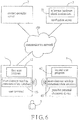
- the portable personal electronic device 4 is capable of connection with the communication network 100 and/or short-distance connection with the user terminal 1 (see, for instance, Figure 6 ).
- the identity of the user 5 is successfully authenticated by the network authentication system, the user 5 is allowed data access to the content-provider server 2 using the user terminal 1.
- Figure 2 is a flow chart of the first preferred embodiment of the network authentication method illustrating how the identity of the user 5 is verified.
- the first preferred embodiment of the network authentication method includes the following steps.
- step S21 the user 5 inputs user login data using a user input interface (not shown) of the user terminal 1 at a website provided by the content-provider server 2.
- the user login data is then transmitted from the user terminal 1 to the content-provider server 2 via the communication network 100.
- the user login data includes a user identification (ID) serving as a user identifier, and a password.
- ID user identification
- step S22 upon receipt of the user login data from the user terminal 1, the content-provider server 2 checks whether the user login data is correct. If the result is affirmative, the flow proceeds to step S23. Otherwise, the content-provider server 2 sends an error message to the user terminal 1 for displaying on a display device (not shown) of the user terminal 1 (step S20).
- step S23 the content-provider server 2 transmits a verification request, which includes the user identifier, to the verification server 3 via the communication network 100.
- the verification server 3 may be regarded as a third party appointed by the content-provider server 2 to perform identity authentication.
- step S24 after receipt of the verification request from the content-provider server 2, the verification server 3 further receives hardware identification data and positioning information that are associated with the user terminal 1 and the portable personal electronic device 4.
- the user terminal 1 includes a global positioning system (GPS) module 11, and pre-stores a first scan program 12.
- the portable personal electronic device 4 may be, but is not limited to, a smart phone or a tablet computer, includes a GPS module 41, and pre-stores a second scan program 42.
- two different network addresses e.g., IP addresses, are assigned respectively to the user terminal 1 and the portable personal electronic device 4.
- Figure 3 shows a first procedure to be performed between steps S23 and S24, illustrating how the hardware identification data and the positioning information are provided to the verification server 3.
- the first procedure includes the following steps.
- step S31 after transmitting the verification request to the verification server 3, the content-provider server 2 further transmits first and second data requests respectively to the user terminal 1 and the portable personal electronic device 4 via the communication network 100.
- step S32 in response to the first data request from the content-provider server 2, the user terminal 1 performs GPS positioning using the GPS module 11 so as to obtain first positioning data that corresponds to a geographical location of the user terminal 1, executes the first scan program 12 to obtain a first combination of identification codes of certain ones of a plurality of hardware components of the user terminal 1, and transmits the first positioning data and the first combination of the identification codes to the verification server 3 via the communication network 100. It is noted that since generation of the first combination of the identification codes using execution of the first scan program 12 is known to those skilled in the art, details of the same are omitted herein for the sake of brevity.
- step S33 in response to the second data request from the content-provider server 2, the portable personal electronic device 4 performs GPS positioning using the GPS module 41 so as to obtain second positioning data that corresponds to a current geographical location of the portable personal electronic device 4, executes the second scan program 42 to obtain a second combination of identification codes of certain ones of a plurality of hardware components of the portable personal electronic device 4, and transmits the second positioning data and the second combination of the identification codes to the verification server 3 via the communication network 100.
- the first combination of the identification codes from the user terminal 1 and the second combination of the identification codes from the portable personal electronic device 4 cooperatively constitute the hardware identification data received by the verification server 3 in step S24.
- the first positioning data from the user terminal 1 and the second positioning data from the portable personal electronic device 4 cooperatively constitute the positioning information received by the verification server 3 in step S24.
- FIG. 4 shows a second procedure to be conducted between step S23 and step S24, illustrating how the hardware identification data and the positioning information are provided to the verification server 3.
- the second procedure includes the following steps.
- step S41 the content-provider server 2 transmits a first data request to the user terminal 1 via the communication network 100.
- the verification server 3 in response to receipt of the verification request from the content-provider server 2, transmits a second data request to the portable personal electronic device 4 via the communication network 100.
- step S43 similar to step S32 of Figure 3 , the first combination of the identification codes, and the first positioning data both generated by the user terminal 1 are transmitted from the user terminal 1 to the verification server 3 via the communication network 100.
- step S44 similar to step S33 of Figure 3 , the second combination of the identification codes, and the second positioning data both generated by the portable personal electronic device 4 are transmitted from the portable personal electronic device 4 to the verification server 3 via the communication network 100.
- FIG. 5 shows a third procedure to be performed between step S23 and step S24, illustrating how the hardware identification data and the positioning information are provided to the verification server 3.
- the third procedure includes the following steps.
- step S51 similar to step S41 of Figure 4
- the first data request is transmitted from the content-provider server 2 to the user terminal 1.
- step S52 similar to step S43 of Figure 4
- the first combination of the identification codes, and the first positioning data both generated by the user terminal 1 are transmitted from the user terminal 1 to the verification server 3 via the communication network 100.
- step S53 of the third procedure essentially involves the periodic generation and transmission of the second positioning data and the second combination of the identification codes to the verification server 3 by the portable personal electronic device 4.
- the first combination of the identification codes from the user terminal 1, and the second combination of the identification codes, which is most recently received by the verification server 3 in step S24after the verification server 3 has received the verification request cooperatively constitute the hardware identification data.
- the first positioning data from the user terminal 1, and the second positioning data, which is most recently received by the verification server 3 in step S24 cooperatively constitute the positioning information.
- the user terminal 1 includes a short-distance wireless communication interface 13, and pre-stores the first scan program 12.
- the portable personal electronic device 4 is unable to connect with the communication network 100, includes a short-distance wireless communication interface 43, and pre-stores the second scan program 42.
- the short-distance wireless communication interfaces 13, 43 may use near field communication (NFC), Bluetooth or wireless fidelity (Wi-Fi) technology.
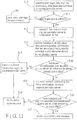
- Figure 7 shows a fourth procedure to be performed between step S23 and step S24 by the network authentication system of Figure 6 , illustrating how the hardware identification data and the positioning information are provided to the verification server 3.
- the fourth procedure includes the following steps.
- step S71 similar to step S41 of Figure 4 , the first data request is transmitted from the content-provider server 2 to the user terminal 1.
- step S72 in response to the first data request from the content-provider server 2, the user terminal 1 executes the first scan program 12 to obtain the first combination of the identification codes.
- the portable personal electronic device 4 is in close proximity to the user terminal 1 to establish a short-distance wireless communication link therewith using the short-distance wireless communication interfaces 13, 43, the user terminal 1 transmits the second data request to the portable personal electronic device 4 through the short-distance wireless communication link.
- step S73 in response to the second data request from the user terminal 1, the portable personal electronic device 4 executes the second scan program 42 to obtain the second combination of the identification codes and transmits the second combination of the identification codes to the user terminal 1 through the short-distance wireless communication link.
- the second combination of the identification codes serves as identification data associated with the portable personal electronic device 4.
- the user terminal 1 transmits, to the verification server 3 via the communication network 100, the hardware identification data, which consists of the first combination of the identification codes and the second combination of the identification codes, i.e., the identification data, as well as the positioning information, which indicates that the user terminal 1 and the portable personal electronic device 4 share the same network address, i.e., the network address assigned to the user terminal 1.
- the hardware identification data and the positioning information are obtained by the verification server 3.
- the portable personal electronic device 4 may be an electronic card, and pre-stores an identification code, which uniquely corresponds to the portable personal electronic device 4 (the electronic card) .
- the short-distance wireless communication interfaces 13, 43 may use radio frequency identification (RFID) technology.
- FIG 9 shows a fifth procedure to be performed between step S23 and step S24 by the network authentication system of Figure 8 , illustrating how the hardware identification data and the positioning information are provided to the verification server 3 .
- the fifth procedure includes the following steps.
- step S91 similar to step S71 of Figure 7 , the first data request is transmitted from the content-provider server 2 to the user terminal 1.
- step S92 similar to step S72 of Figure 7 , the first combination of the identification codes is generated by the user terminal 1, and the second data request is transmitted from the user terminal 1 to the portable personal electronic device 4 using short-distance wireless communication.
- step S93 in response to the second data request from the user terminal 1, the portable personal electronic device 4 transmits the identification code, which serves as the identification data, to the user terminal 1 using short-distance wireless communication.
- step S94 the user terminal 1 transmits the hardware identification data, which consists of the first combination of the identification codes and the identification code, i.e., the identification data, and the positioning information, which indicates that the user terminal 1 and the portable personal electronic device 4 are in close proximity to each other, via the communication network 100.
- the hardware identification data and the positioning information are obtained by the verification server 3.
- step S24 the method proceeds to step S25, where in response to the verification request, the verification server 3 determines whether the hardware identification data obtained thereby matches reference hardware identification data 31, which is pre-stored therein and which corresponds to the user identifier, i.e., the user ID. If the hardware identification data is determined to be a subset of the reference hardware identification data 31, the flow proceeds to step S26. Otherwise, the flow goes to step S28.
- the user terminal 1 and the portable personal electronic device 4 provided by the same owner are registered in the content-provider server 2, and are loaded respectively with the first scan program 12, and the second scan program 42 ( Figures 1 and 6 ) or the identification code ( Figure 8 ). Thereafter, the first and second scan programs 12, 42 are executed respectively by the user terminal 1 and the portable personal electronic device 4 to obtain the identification codes of the hardware components of the user terminal 1, and the identification codes of the hardware components of the portable personal electronic device 4 that cooperatively constitute the reference hardware identification data 31 corresponding to the user identifier of the owner.
- the first and second scan programs 12, 42 may obtain the identification codes of the certain ones of the hardware components of the user terminal 1, and the identification codes of the certain ones of the hardware components of the portable personal electronic device 4 to cooperatively constitute the reference hardware identification data 31.
- the identification codes obtained using execution of the first scan program 12 and associated with the user terminal 1, the identification code loaded in the portable personal electronic device 4 cooperatively constitute the reference hardware identification data 31 corresponding to the user identifier of the owner. Then, the reference hardware identification data 31 is stored in the verification server 3 for authentication purposes.
- the user terminal 1 operated by the user 5 and the portable personal electronic device 4 carried by the user 5 belong to the same owner.
- step S26 the verification server 3 determines, based on the positioning information, whether the user terminal 1 and the portable personal electronic device 4 are in close proximity to each other. For example, when the first positioning data generated in sub-steps S32, S43 and S52 of Figures 3 , 4 and 5 is identical to the second positioning data generated in sub-steps S33, S44 and S53 of Figures 3 , 4 and 5 , when the positioning information transmitted in sub-step S74 of Figure 7 indicates that the user terminal 1 and the portable personal electronic device 4 share the same network address or when the positioning information transmitted in sub-step S94 of Figure 9 indicates that the user terminal 1 and the portable personal electronic device 4 are in close proximity to each other, the verification server 4 determines that the user terminal 1 and the portable personal electronic device 4 are in close proximity to each other, and the flow then proceeds to step S27. Otherwise, the flow goes to step S28.
- step S26 when the user terminal 1 and the portable personal electronic device 4 are in close proximity to each other (step S26) while an affirmative determination is made in step S25, the user 5 is verified as the owner of the user terminal 1 and the portable personal electronic device 4.
- step S27 the verification server 3 transmits a verification reply indicating successful authentication of the identity of the user 5 to the content-provider server 2 via the communication network 100.
- the user 5 is allowed data access to the content-provider server 2.
- step S28 the verification server 3 transmits a verification reply indicating failed authentication of the identity of the user 5 to the content-provider server 2 via the communication network. Thus, the user 5 is denied data access to the content-provider server 2.
- FIG. 10 another network authentication system, which is a modification of the network authentication system of Figure 1 , is used to implement the second preferred embodiment of a network authentication method for secure identification of the identity of a user 5 according to the present invention.
- the user terminal 1' of the network authentication system of Figure 10 may be, but is not limited to, a point of sale (POS) terminal or an automated teller machine (ATM), and pre-stores first positioning data 14 corresponding to a geographical location of the user terminal 1'.
- the portable personal electronic device 4' is a portable personal communication device 4', which may be, but is not limited to, a smart phone or a tablet computer.
- the portable personal communication device 4' includes a GPS module 41, and pre-stores a scan program 42'. In this embodiment, if the identity of the user 5 is successfully authenticated by the network authentication system of Figure 10 , the user 5 is allowed data access to the content-provider server 2.
- Figure 11 is a flow chart of the second preferred embodiment of the network authentication method illustrating how the identity of the user 5 is verified.
- the second preferred embodiment of the network authentication method includes the following steps.
- step S10 the user 5 inputs user login data using a user input interface (not shown) of the user terminal 1' at a website provided by the content-provider server 2. Then, the user terminal 1' transmits the user login data and the first positioning data to the content-provider server 2 via the communication network 100.
- the user login data includes a user identification (ID) serving as a user identifier, and a password.
- step S11 upon receipt of the user login data and the first positioning data from the user terminal 1', the content-provider server 2 checks whether the user login data is correct. If the result is affirmative, the flow proceeds to step S12. Otherwise, the content-provider server 2 sends an error message to the user terminal 1' for displaying on a display device (not shown) of the user terminal 1' (step S9).
- step S12 the content-provider server 2 transmits a first request, which includes the user identifier, to the verification server 3 via the communication network 100.
- the verification server 3 may be regarded as a third party appointed by the content-provider server 2 to perform hardware identification authentication.
- step S13 after receipt of the first request from the content-provider server 2, the verification server 3 further receives hardware identification data and positioning information that are associated with the portable personal communication device 4' from the portable personal communication device 4' via the communication network 100. In one example, in response to the first request from the content-provider server 2, the verification server 3 transmits a second request for the hardware identification data and the second positioning data to the portable personal communication device 4' via the communication network 100.
- the portable personal communication device 4' performs GPS positioning to generate the second positioning data that corresponds to a current geographical location of the portable personal communication device 4', executes the scan program 42' to obtain a combination of identification codes of certain ones of a plurality of hardware components (not shown) of the portable personal communication device 4' that serves as the hardware identification data, and transmits the second positioning data and the hardware identification data to the verification server 3 via the communication network 100.
- the portable personal communication device 4' is operable to perform GPS positioning so as to obtain the second positioning data in a periodic manner, to execute the scan program 42' to obtain the combination of the identification codes that serves as the hardware identification data automatically, and to transmit the second positioning data and the hardware identification data to the verification server via the communication network 100 in a periodic manner.
- the verification server 3 receives the hardware identification data and the second positioning data periodically.
- step S14 the verification server 3 determines whether the hardware identification data obtained thereby is a subset of reference hardware identification data 31, which is pre-stored in the verification server 3 and which corresponds to the user identifier. If the result of the determination is affirmative, the flow proceeds to step S15. Otherwise, the flow goes to step S18.
- step S15 the verification server 3 transmits the second positioning data to the content-provider server 2. It should be noted that, when the portable personal communication device 4' periodically transmits the hardware identification data and the second positioning data, the second positioning data, which is most recently received by the verification server 3 in step S13 after receipt of the first request from the content-provider server 2, is transmitted to the content-provider server 2.
- step S16 the content-provider server 2 determines, based on the first positioning data and the second positioning data, whether the user terminal 1' and the portable personal communication device 4' are in close proximity to each other.
- the content-provider server 2 detects that the first positioning data is identical to the second positioning data
- the content-provider server 2 determines that the user terminal 1' and the portable personal communication device 4' are in close proximity to each other.
- the content-provider server 2 deems that the identity of the user 5 has been successfully authenticated (step S17).
- the user 5 is allowed data access to the content-provider server 2 using the user terminal 1' . Otherwise, the flow goes to step S19.
- step S18 when the hardware identification data is not found to be a subset of the reference hardware identification data 31, the verification server 3 transmits a failed verification reply to the content-provider server 2.
- step S19 in response to the failed verification reply from the verification server 3 in step S18, or when the user terminal 1' is determined as not in close proximity to the portable personal communication device 4' in step S16, the content-provider server 2 deems that authentication of the identity of the user 5 has failed. Thus, the user 5 is denied data access to the content-provider server 2.
- the network authentication method of this invention utilizes hardware identification verification and positioning verification for the user terminal 1, 1' and the portable personal electronic device 4, 4'. Accordingly, it is relatively difficult for hackers to simultaneously steal hardware and positioning information associated with the user terminal 1, 1' and the portable personal electronic device 4, 4', thereby ensuring secure verification of the identity of the user 5. Further, the user' s own smart phone or tablet computer is used as the portable personal electronic device 4, 4' without requiring additional identity verification devices. Therefore, the cost of identity authentication for the content-provider server 2 is minimized.
Landscapes
- Engineering & Computer Science (AREA)
- Computer Security & Cryptography (AREA)
- Computer Hardware Design (AREA)
- Computing Systems (AREA)
- General Engineering & Computer Science (AREA)
- Computer Networks & Wireless Communication (AREA)
- Signal Processing (AREA)
- Power Engineering (AREA)
- Mobile Radio Communication Systems (AREA)
- Telephonic Communication Services (AREA)
Description
- The invention relates to network identity authentication, and more particularly to a network authentication method for secure verification of identity of a user.
- Currently, various web transactions have become increasingly popular. In order to secure the web transactions, user identity authentication is absolutely necessary. However, due to the increasing numbers of web users and web crimes, and the continuous progress of criminal techniques, for example, an Internet content provider (ICP) needs to provide an identity verification device for each user. Thus, the cost of customer service for personalization, distribution and troubleshooting is considerable. Further, it is quite inconvenient that the user needs to have different identity verification devices for different ICPs. Moreover, aside from intercepting and stealing user IDs and passwords, hackers also try to manipulate transaction data. Therefore, the ICP is often forced to change hardware equipments, thereby generating additional cost.
- Therefore, an object of the present invention is to provide a network authentication method for secure verification of the identity of a user that can overcome the aforesaid drawbacks of the prior art.
-
US 2004/250074 A1 discloses a method for providing secure access to an application service, in which a security token and a proximity token check that their locations are close to each other before initiating cryptographic processing between the security token and the application service.GB 2 492 614 AEP 2 506 525 A1 - According to one aspect of the present invention, there is provided a network authentication method according to independent claim 1. According to another aspect of the present invention, there is provided a network authentication method according to
independent claim 11. Other features and advantages of the present invention will become apparent in the following detailed description of the preferred embodiments with reference to the accompanying drawings, of which: -
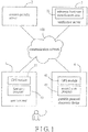
Figure 1 is a schematic block diagram illustrating a network authentication system that is configured for implementing the first preferred embodiment of a network authentication method according to the present invention; -
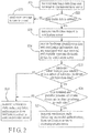
Figure 2 is a flow chart illustrating the first preferred embodiment; -
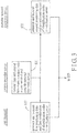
Figure 3 is a flow chart of a first procedure between steps S23 and S24 of the first preferred embodiment; -
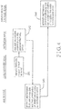
Figure 4 is a flow chart of a second procedure between steps S23 and S24 of the first preferred embodiment; -
Figure 5 is a flow chart of a third procedure between steps S23 and S24 of the first preferred embodiment; -
Figure 6 is a schematic block diagram illustrating a first variation of the network authentication system; -
Figure 7 is a flow chart of a fourth procedure between steps S23 and S24 of the first preferred embodiment to be implemented by the first variation of the network authentication system ofFigure 6 ; -
Figure 8 is a schematic block diagram illustrating a second variation of the network authentication system; -
Figure 9 is a flow chart of a fifth procedure between steps S23 and S24 of the first preferred embodiment to be implemented by the second variation of the network authentication system ofFigure 8 ; -
Figure 10 is a schematic block diagram illustrating another network authentication system that is configured for implementing the second preferred embodiment of a network authentication method according to the present invention; and -
Figure 11 is a flow chart illustrating the second preferred embodiment. - Before the present invention is described in greater detail, it should be noted that like elements are denoted by the same reference numerals throughout the disclosure.
- Referring to
Figure 1 , a network authentication system is used to implement the first preferred embodiment of a network authentication method for secure identification of the identity of auser 5 according to the present invention. The network authentication system includes a user terminal 1, such as a personal computer or a notebook computer, operated by theuser 5, a content-provider server 2, such as the server of an Internet content provider (ICP), averification server 3, and a portable personalelectronic device 4 carried by theuser 5. The user terminal 1, the content-provider server 2 and theverification server 3 are connected to acommunication network 100, such as the Internet. The portable personalelectronic device 4 is capable of connection with thecommunication network 100 and/or short-distance connection with the user terminal 1 (see, for instance,Figure 6 ). In this embodiment, if the identity of theuser 5 is successfully authenticated by the network authentication system, theuser 5 is allowed data access to the content-provider server 2 using the user terminal 1. -
Figure 2 is a flow chart of the first preferred embodiment of the network authentication method illustrating how the identity of theuser 5 is verified. The first preferred embodiment of the network authentication method includes the following steps. - In step S21, the
user 5 inputs user login data using a user input interface (not shown) of the user terminal 1 at a website provided by the content-provider server 2. The user login data is then transmitted from the user terminal 1 to the content-provider server 2 via thecommunication network 100. In this embodiment, the user login data includes a user identification (ID) serving as a user identifier, and a password. - In step S22, upon receipt of the user login data from the user terminal 1, the content-
provider server 2 checks whether the user login data is correct. If the result is affirmative, the flow proceeds to step S23. Otherwise, the content-provider server 2 sends an error message to the user terminal 1 for displaying on a display device (not shown) of the user terminal 1 (step S20). - In step S23, the content-
provider server 2 transmits a verification request, which includes the user identifier, to theverification server 3 via thecommunication network 100. In this embodiment, theverification server 3 may be regarded as a third party appointed by the content-provider server 2 to perform identity authentication. - In step S24, after receipt of the verification request from the content-
provider server 2, theverification server 3 further receives hardware identification data and positioning information that are associated with the user terminal 1 and the portable personalelectronic device 4. For example, as shown inFigure 1 , the user terminal 1 includes a global positioning system (GPS)module 11, and pre-stores afirst scan program 12. The portable personalelectronic device 4 may be, but is not limited to, a smart phone or a tablet computer, includes aGPS module 41, and pre-stores asecond scan program 42. In this example, two different network addresses, e.g., IP addresses, are assigned respectively to the user terminal 1 and the portable personalelectronic device 4.Figure 3 shows a first procedure to be performed between steps S23 and S24, illustrating how the hardware identification data and the positioning information are provided to theverification server 3. The first procedure includes the following steps. In step S31, after transmitting the verification request to theverification server 3, the content-provider server 2 further transmits first and second data requests respectively to the user terminal 1 and the portable personalelectronic device 4 via thecommunication network 100. In step S32, in response to the first data request from the content-provider server 2, the user terminal 1 performs GPS positioning using theGPS module 11 so as to obtain first positioning data that corresponds to a geographical location of the user terminal 1, executes thefirst scan program 12 to obtain a first combination of identification codes of certain ones of a plurality of hardware components of the user terminal 1, and transmits the first positioning data and the first combination of the identification codes to theverification server 3 via thecommunication network 100. It is noted that since generation of the first combination of the identification codes using execution of thefirst scan program 12 is known to those skilled in the art, details of the same are omitted herein for the sake of brevity. In step S33, in response to the second data request from the content-provider server 2, the portable personalelectronic device 4 performs GPS positioning using theGPS module 41 so as to obtain second positioning data that corresponds to a current geographical location of the portable personalelectronic device 4, executes thesecond scan program 42 to obtain a second combination of identification codes of certain ones of a plurality of hardware components of the portable personalelectronic device 4, and transmits the second positioning data and the second combination of the identification codes to theverification server 3 via thecommunication network 100. Thus, the first combination of the identification codes from the user terminal 1 and the second combination of the identification codes from the portable personalelectronic device 4 cooperatively constitute the hardware identification data received by theverification server 3 in step S24. The first positioning data from the user terminal 1 and the second positioning data from the portable personalelectronic device 4 cooperatively constitute the positioning information received by theverification server 3 in step S24. -
Figure 4 shows a second procedure to be conducted between step S23 and step S24, illustrating how the hardware identification data and the positioning information are provided to theverification server 3. The second procedure includes the following steps. In step S41, the content-provider server 2 transmits a first data request to the user terminal 1 via thecommunication network 100. In step S42, in response to receipt of the verification request from the content-provider server 2, theverification server 3 transmits a second data request to the portable personalelectronic device 4 via thecommunication network 100. In step S43, similar to step S32 ofFigure 3 , the first combination of the identification codes, and the first positioning data both generated by the user terminal 1 are transmitted from the user terminal 1 to theverification server 3 via thecommunication network 100. In step S44, similar to step S33 ofFigure 3 , the second combination of the identification codes, and the second positioning data both generated by the portable personalelectronic device 4 are transmitted from the portable personalelectronic device 4 to theverification server 3 via thecommunication network 100. -
Figure 5 shows a third procedure to be performed between step S23 and step S24, illustrating how the hardware identification data and the positioning information are provided to theverification server 3. The third procedure includes the following steps. In step S51, similar to step S41 ofFigure 4 , the first data request is transmitted from the content-provider server 2 to the user terminal 1. In step S52, similar to step S43 ofFigure 4 , the first combination of the identification codes, and the first positioning data both generated by the user terminal 1 are transmitted from the user terminal 1 to theverification server 3 via thecommunication network 100. However, unlike the first and second procedures, the portable personalelectronic device 4 is operable to perform GPS positioning so as to obtain the second positioning data in a periodic manner, to automatically execute thesecond scan program 42 to obtain the second combination of the identification codes, and to transmit the second positioning data and the second combination of the identification codes to theverification server 3 in a periodic manner. Therefore, step S53 of the third procedure essentially involves the periodic generation and transmission of the second positioning data and the second combination of the identification codes to theverification server 3 by the portable personalelectronic device 4. In this case, the first combination of the identification codes from the user terminal 1, and the second combination of the identification codes, which is most recently received by theverification server 3 in step S24after theverification server 3 has received the verification request, cooperatively constitute the hardware identification data. The first positioning data from the user terminal 1, and the second positioning data, which is most recently received by theverification server 3 in step S24, cooperatively constitute the positioning information. - Referring to
Figure 6 , a first variation of the network authentication system is shown. Unlike the network authentication system ofFigure 1 , the user terminal 1 includes a short-distancewireless communication interface 13, and pre-stores thefirst scan program 12. The portable personalelectronic device 4 is unable to connect with thecommunication network 100, includes a short-distancewireless communication interface 43, and pre-stores thesecond scan program 42. The short-distance wireless communication interfaces 13, 43 may use near field communication (NFC), Bluetooth or wireless fidelity (Wi-Fi) technology.Figure 7 shows a fourth procedure to be performed between step S23 and step S24 by the network authentication system ofFigure 6 , illustrating how the hardware identification data and the positioning information are provided to theverification server 3. The fourth procedure includes the following steps. In step S71, similar to step S41 ofFigure 4 , the first data request is transmitted from the content-provider server 2 to the user terminal 1. In step S72, in response to the first data request from the content-provider server 2, the user terminal 1 executes thefirst scan program 12 to obtain the first combination of the identification codes. When the portable personalelectronic device 4 is in close proximity to the user terminal 1 to establish a short-distance wireless communication link therewith using the short-distance wireless communication interfaces 13, 43, the user terminal 1 transmits the second data request to the portable personalelectronic device 4 through the short-distance wireless communication link. In step S73, in response to the second data request from the user terminal 1, the portable personalelectronic device 4 executes thesecond scan program 42 to obtain the second combination of the identification codes and transmits the second combination of the identification codes to the user terminal 1 through the short-distance wireless communication link. In this case, the second combination of the identification codes serves as identification data associated with the portable personalelectronic device 4. In step S74, the user terminal 1 transmits, to theverification server 3 via thecommunication network 100, the hardware identification data, which consists of the first combination of the identification codes and the second combination of the identification codes, i.e., the identification data, as well as the positioning information, which indicates that the user terminal 1 and the portable personalelectronic device 4 share the same network address, i.e., the network address assigned to the user terminal 1. Thus, the hardware identification data and the positioning information are obtained by theverification server 3. - Referring to
Figure 8 , a second variation of the network authentication system is shown. Unlike the network authentication system ofFigure 6 , the portable personalelectronic device 4 may be an electronic card, and pre-stores an identification code, which uniquely corresponds to the portable personal electronic device 4 (the electronic card) . In addition, the short-distance wireless communication interfaces 13, 43 may use radio frequency identification (RFID) technology.Figure 9 shows a fifth procedure to be performed between step S23 and step S24 by the network authentication system ofFigure 8 , illustrating how the hardware identification data and the positioning information are provided to theverification server 3 . The fifth procedure includes the following steps. In step S91, similar to step S71 ofFigure 7 , the first data request is transmitted from the content-provider server 2 to the user terminal 1. In step S92, similar to step S72 ofFigure 7 , the first combination of the identification codes is generated by the user terminal 1, and the second data request is transmitted from the user terminal 1 to the portable personalelectronic device 4 using short-distance wireless communication. In step S93, in response to the second data request from the user terminal 1, the portable personalelectronic device 4 transmits the identification code, which serves as the identification data, to the user terminal 1 using short-distance wireless communication. In step S94, the user terminal 1 transmits the hardware identification data, which consists of the first combination of the identification codes and the identification code, i.e., the identification data, and the positioning information, which indicates that the user terminal 1 and the portable personalelectronic device 4 are in close proximity to each other, via thecommunication network 100. Thus, the hardware identification data and the positioning information are obtained by theverification server 3. - Referring back to
Figures 1 and2 , after step S24, the method proceeds to step S25, where in response to the verification request, theverification server 3 determines whether the hardware identification data obtained thereby matches referencehardware identification data 31, which is pre-stored therein and which corresponds to the user identifier, i.e., the user ID. If the hardware identification data is determined to be a subset of the referencehardware identification data 31, the flow proceeds to step S26. Otherwise, the flow goes to step S28. - It should be noted that, during a registration procedure prior to authentication, the user terminal 1 and the portable personal
electronic device 4 provided by the same owner are registered in the content-provider server 2, and are loaded respectively with thefirst scan program 12, and the second scan program 42 (Figures 1 and6 ) or the identification code (Figure 8 ). Thereafter, the first andsecond scan programs electronic device 4 to obtain the identification codes of the hardware components of the user terminal 1, and the identification codes of the hardware components of the portable personalelectronic device 4 that cooperatively constitute the referencehardware identification data 31 corresponding to the user identifier of the owner. In an alternative, the first andsecond scan programs electronic device 4 to cooperatively constitute the referencehardware identification data 31. Alternatively, the identification codes obtained using execution of thefirst scan program 12 and associated with the user terminal 1, the identification code loaded in the portable personalelectronic device 4 cooperatively constitute the referencehardware identification data 31 corresponding to the user identifier of the owner. Then, the referencehardware identification data 31 is stored in theverification server 3 for authentication purposes. Therefore, if the hardware identification data is determined to be a subset of the reference hardware identification data 31 (or a complete match in the alternative case) in step S25, the user terminal 1 operated by theuser 5 and the portable personalelectronic device 4 carried by theuser 5 belong to the same owner. - In step S26, the
verification server 3 determines, based on the positioning information, whether the user terminal 1 and the portable personalelectronic device 4 are in close proximity to each other. For example, when the first positioning data generated in sub-steps S32, S43 and S52 ofFigures 3 ,4 and5 is identical to the second positioning data generated in sub-steps S33, S44 and S53 ofFigures 3 ,4 and5 , when the positioning information transmitted in sub-step S74 ofFigure 7 indicates that the user terminal 1 and the portable personalelectronic device 4 share the same network address or when the positioning information transmitted in sub-step S94 ofFigure 9 indicates that the user terminal 1 and the portable personalelectronic device 4 are in close proximity to each other, theverification server 4 determines that the user terminal 1 and the portable personalelectronic device 4 are in close proximity to each other, and the flow then proceeds to step S27. Otherwise, the flow goes to step S28. - It should be noted that, when the user terminal 1 and the portable personal
electronic device 4 are in close proximity to each other (step S26) while an affirmative determination is made in step S25, theuser 5 is verified as the owner of the user terminal 1 and the portable personalelectronic device 4. - In step S27, the
verification server 3 transmits a verification reply indicating successful authentication of the identity of theuser 5 to the content-provider server 2 via thecommunication network 100. Thus, theuser 5 is allowed data access to the content-provider server 2. - In step S28, the
verification server 3 transmits a verification reply indicating failed authentication of the identity of theuser 5 to the content-provider server 2 via the communication network. Thus, theuser 5 is denied data access to the content-provider server 2. - Referring to
Figure 10 , another network authentication system, which is a modification of the network authentication system ofFigure 1 , is used to implement the second preferred embodiment of a network authentication method for secure identification of the identity of auser 5 according to the present invention. Unlike the network authentication system ofFigure 1 , the user terminal 1' of the network authentication system ofFigure 10 may be, but is not limited to, a point of sale (POS) terminal or an automated teller machine (ATM), and pre-storesfirst positioning data 14 corresponding to a geographical location of the user terminal 1'. In addition, the portable personal electronic device 4' is a portable personal communication device 4', which may be, but is not limited to, a smart phone or a tablet computer. The portable personal communication device 4' includes aGPS module 41, and pre-stores a scan program 42'. In this embodiment, if the identity of theuser 5 is successfully authenticated by the network authentication system ofFigure 10 , theuser 5 is allowed data access to the content-provider server 2. -
Figure 11 is a flow chart of the second preferred embodiment of the network authentication method illustrating how the identity of theuser 5 is verified. The second preferred embodiment of the network authentication method includes the following steps. - In step S10, the
user 5 inputs user login data using a user input interface (not shown) of the user terminal 1' at a website provided by the content-provider server 2. Then, the user terminal 1' transmits the user login data and the first positioning data to the content-provider server 2 via thecommunication network 100. In this embodiment, the user login data includes a user identification (ID) serving as a user identifier, and a password. - In step S11, upon receipt of the user login data and the first positioning data from the user terminal 1', the content-
provider server 2 checks whether the user login data is correct. If the result is affirmative, the flow proceeds to step S12. Otherwise, the content-provider server 2 sends an error message to the user terminal 1' for displaying on a display device (not shown) of the user terminal 1' (step S9). - In step S12, the content-
provider server 2 transmits a first request, which includes the user identifier, to theverification server 3 via thecommunication network 100. In this embodiment, theverification server 3 may be regarded as a third party appointed by the content-provider server 2 to perform hardware identification authentication. - In step S13, after receipt of the first request from the content-
provider server 2, theverification server 3 further receives hardware identification data and positioning information that are associated with the portable personal communication device 4' from the portable personal communication device 4' via thecommunication network 100. In one example, in response to the first request from the content-provider server 2, theverification server 3 transmits a second request for the hardware identification data and the second positioning data to the portable personal communication device 4' via thecommunication network 100. Thus, in response to the second request from theverification server 3, the portable personal communication device 4' performs GPS positioning to generate the second positioning data that corresponds to a current geographical location of the portable personal communication device 4', executes the scan program 42' to obtain a combination of identification codes of certain ones of a plurality of hardware components (not shown) of the portable personal communication device 4' that serves as the hardware identification data, and transmits the second positioning data and the hardware identification data to theverification server 3 via thecommunication network 100. In another example, the portable personal communication device 4' is operable to perform GPS positioning so as to obtain the second positioning data in a periodic manner, to execute the scan program 42' to obtain the combination of the identification codes that serves as the hardware identification data automatically, and to transmit the second positioning data and the hardware identification data to the verification server via thecommunication network 100 in a periodic manner. Thus, theverification server 3 receives the hardware identification data and the second positioning data periodically. - In step S14, the
verification server 3 determines whether the hardware identification data obtained thereby is a subset of referencehardware identification data 31, which is pre-stored in theverification server 3 and which corresponds to the user identifier. If the result of the determination is affirmative, the flow proceeds to step S15. Otherwise, the flow goes to step S18. - In step S15, the
verification server 3 transmits the second positioning data to the content-provider server 2. It should be noted that, when the portable personal communication device 4' periodically transmits the hardware identification data and the second positioning data, the second positioning data, which is most recently received by theverification server 3 in step S13 after receipt of the first request from the content-provider server 2, is transmitted to the content-provider server 2. - In step S16, the content-
provider server 2 determines, based on the first positioning data and the second positioning data, whether the user terminal 1' and the portable personal communication device 4' are in close proximity to each other. When the content-provider server 2 detects that the first positioning data is identical to the second positioning data, the content-provider server 2 determines that the user terminal 1' and the portable personal communication device 4' are in close proximity to each other. Then, the content-provider server 2 deems that the identity of theuser 5 has been successfully authenticated (step S17). Thus, theuser 5 is allowed data access to the content-provider server 2 using the user terminal 1' . Otherwise, the flow goes to step S19. - In step S18, when the hardware identification data is not found to be a subset of the reference
hardware identification data 31, theverification server 3 transmits a failed verification reply to the content-provider server 2. - In step S19, in response to the failed verification reply from the
verification server 3 in step S18, or when the user terminal 1' is determined as not in close proximity to the portable personal communication device 4' in step S16, the content-provider server 2 deems that authentication of the identity of theuser 5 has failed. Thus, theuser 5 is denied data access to the content-provider server 2. - In sum, the network authentication method of this invention utilizes hardware identification verification and positioning verification for the user terminal 1, 1' and the portable personal
electronic device 4, 4'. Accordingly, it is relatively difficult for hackers to simultaneously steal hardware and positioning information associated with the user terminal 1, 1' and the portable personalelectronic device 4, 4', thereby ensuring secure verification of the identity of theuser 5. Further, the user' s own smart phone or tablet computer is used as the portable personalelectronic device 4, 4' without requiring additional identity verification devices. Therefore, the cost of identity authentication for the content-provider server 2 is minimized.
Claims (14)
- A network authentication method to be implemented by a network authentication system for secure verification of the identity of a user (5), the network authentication system including a user terminal (1) operated by the user (5), a content-provider server (2), a verification server (3), and a portable personal electronic device (4) carried by the user (5), the user terminal (1), the content-provider server (2) and the verification server (3) being connected to a communication network (100), the portable personal electronic device (4) being capable of connection with the communication network (100) and/or short-distance wireless communication with the user terminal (1), said network authentication method being characterized by the steps of:a) upon receipt of correct user login data, which includes a user identifier, from the user terminal (1) via the communication network (100), the content-provider server (2) transmitting a verification request, which includes the user identifier, to the verification server (3) via the communication network (100);b) after receipt of the verification request from the content-provider server (2), the verification server (3) further receiving hardware identification data and positioning information that are associated with the user terminal (1) and the portable personal electronic device (4) via the communication network (100);c) in response to the verification request, the verification server (3) determining whether the hardware identification data obtained in step b) matches or is a subset of reference hardware identification data (31), which is pre-stored in the verification server (3) and which corresponds to the user identifier, and judging, based on the positioning information, whether the user terminal (1) and the portable personal electronic device (4) are in close proximity to each other; andd) upon detecting that a match exists or that the hardware identification data is a subset of the reference hardware identification data (31) and judging that the user terminal (1) and the portable personal electronic device (4) are in close proximity to each other, the verification server (3) transmitting a verification reply indicating successful authentication of the identity of the user (5) to the content-provider server (2) via the communication network (100).
- The network authentication method as claimed in Claim 1, the portable personal electronic device (4) being connected to the communication network (100), two different network addresses being assigned respectively to the user terminal (1) and the portable personal electronic device (4), the network authentication method being further characterized by, between steps a) and b), the steps of:e) the content-provider server (2) transmitting a first data request to the user terminal (1) via the communication network (100);f) in response to the first data request from the content-provider server (2), the user terminal (1) performing global positioning system (GPS) positioning so as to obtain first positioning data corresponding to a geographical location of the user terminal (1), executing a first scan program (12) pre-installed therein to obtain a first combination of identification codes of certain ones of a plurality of hardware components of the user terminal (1), and transmitting the first positioning data and the first combination of the identification codes to the verification server (3) via the communication network (100); andg) the portable personal electronic device (4) performing GPS positioning so as to obtain second positioning data corresponding to a current geographical location of the portable personal electronic device (4), executing a second scan program (42) pre-installed therein to obtain a second combination of identification codes of certain ones of a plurality of hardware components of the portable personal electronic device (4), and transmitting the second positioning data and the second combination of the identification codes to the verification server (3) via the communication network (100); andcharacterized in that the first combination of the identification codes transmitted in step f) and the second combination of the identification codes transmitted in step g) cooperatively constitute the hardware identification data received by the verification server (3) in step b), and the first positioning data transmitted in step f) and the second positioning data transmitted in step g) cooperatively constitute the positioning information received by the verification server (3) in step b).
- The network authentication method as claimed in Claim 2, characterized in that:in step e), the content-provider server (2) further transmits a second data request to the portable personal electronic device (4) via the communication network (100); andin step g), the portable personal electronic device (100) performs GPS positioning and executes the second scan program (42) in response to receipt of the second data request from the content-provider server (2).
- The network authentication method as claimed in Claim 2, being further characterized by, prior to step g), the step of:f') in response to receipt of the verification request from the content-provider server (2), the verification server (3) transmitting a second data request to the portable personal electronic device (4) via the communication network (100); andcharacterized in that, in step g), the portable personal electronic device (4) performs GPS positioning and executes the second scan program (42) in response to receipt of the second data request from the verification server (3).
- The network authentication method as claimed in Claim 2, characterized in that:in step g), the portable personal electronic device (4) performs GPS positioning so as to obtain the second positioning data in a periodic manner, automatically executes the second scan program (42) to obtain the second combination of the identification codes, and transmits the second positioning data and the second combination of the identification codes to the verification server (3) in a periodic manner; andthe first combination of the identification codes transmitted in step f), and the second combination of the identification codes, which is most recently transmitted to the verification server (3) in step g) after the verification server (3) has received the verification request, cooperatively constitute the hardware identification data, and the first positioning data transmitted in step f), and the second positioning data, which is most recently transmitted to the verification server (3) in step g) after the verification server (3) has received the verification request, cooperatively constitute the positioning information.
- The network authentication method as claimed in Claim 2, characterized in that, in step c), the verification server (3) determines that the user terminal (1) and the portable personal electronic device (4) are in close proximity to each other when the first positioning data is identical to the second position data.
- The network authentication method as claimed in Claim 1, the portable personal electronic device (4) being capable of short-distance wireless communication with the user terminal (1), the network authentication method being further characterized by, between steps a) and b), the steps of:h) the content-provider server (2) transmitting a first data request to the user terminal (1) via the communication network (100);i) in response to the first data request from the content-provider server (2), the user terminal (1) executing a first scan program (12) pre-installed therein to obtain a first combination of identification codes of certain ones of a plurality of hardware components of the user terminal (1), and, upon establishing a short-distance wireless communication link with the portable personal electronic device (4), transmitting a second data request to the portable personal electronic device (4) through the short-distance wireless communication link;j) in response to the second data request from the user terminal (1), the portable personal electronic device (4) transmitting identification data associated therewith to the user terminal (1) through the short-distance wireless communication link; andk) the user terminal (1) transmitting the hardware identification data, which consists of the first combination of the identification codes and the identification data, and the positioning information to the verification server (3) via the communication network (100).
- The network authentication method as claimed in Claim 7, characterized in that, in step j), the portable personal electronic device (4) executes a second scan program (42) pre-installed therein to obtain a second combination of identification codes of certain ones of a plurality of hardware components of the portable personal electronic device (4), the second combination of the identification codes serving as the identification data.
- The network authentication method as claimed in Claim 8, characterized in that, in step c), the verification server (3) determines that the user terminal (1) and the portable personal electronic device (4) are in close proximity to each other when the positioning information indicates that the user terminal (1) and the portable personal electronic device (4) share the same network address.
- The network authentication method as claimed in Claim 7, the portable personal electronic device (4) being an electronic card, characterized in that:in step j), the identification data is an identification code, which is pre-stored in and which corresponds uniquely to the electronic card; andin step k), the positioning information indicates that the user terminal (1) and the portable personal electronic device (4) are in close proximity to each other.
- A network authentication method to be implemented by a network authentication system for secure verification of the identity of a user (5), the network authentication system including a user terminal (1) operated by the user (5), a content-provider server (2), a verification server (3), and a portable personal communication device (4') carried by the user (5), the user terminal (1), the content-provider server (2), the verification server (3) and the portable personal communication device (4') being connected to a communication network (100), said network authentication method being characterized by the steps of :a) upon receipt of correct user login data including a user identifier, and of first positioning data corresponding to a geographical location of the user terminal (1) from the user terminal (1) via the communication network (100), the content-provider server (2) transmitting to the verification server (3) a first request, which includes the user identifier, for second positioning data corresponding to a current geographical location of the portable personal communication device (4') via the communication network;b) upon receipt of the first request from the content-provider server (2), the verification server (3) further receiving hardware identification data and second positioning data that are associated with the portable personal communication device (4') from the portable personal communication device (4') via the communication network (100);c) the verification server (3) determining whether the hardware identification data obtained in step b) matches or is a subset of reference hardware identification data (31), which is pre-stored in the verification server (3) and which corresponds to the user identifier, and transmitting the second positioning data to the content-provider server (2) if a match exists or if the hardware identification data is a subset of the reference hardware identification data (31); andd) upon receipt of the second positioning data from the verification server (3), the content-provider server (2) judging, based on the first positioning data received thereby in step a) and the second positioning data transmitted thereto in step c), whether the user terminal (1) and the portable personal communication device (4') are in close proximity to each other, and judging a successful authentication of the identity of the user (5) upon judging that the user terminal (1) and the portable personal communication device (4') are in close proximity to each other.
- The network authentication method as claimed in Claim 11, being further characterized by, between steps a) and b), the steps of:e) in response to the first request from the content-provider server (2), the verification server (3) transmitting a second request for the hardware identification data and the second positioning data to the portable personal communication device (4') via the communication network (100); andf) in response to the second request from the verification server (3), the portable personal communication device (4') performing GPS positioning so as to generate the second positioning data that corresponds to a current geographical location of the portable personal communication device (4'), executing a scan program (42') pre-installed therein to obtain a combination of identification codes of certain ones of a plurality of hardware components of the portable personal communication device (4') that serves as the hardware identification data, and transmitting the second positioning data and the hardware identification data to the verification server (3) via the communication network (100).
- The network authentication method as claimed in Claim 11, being further characterized by the step of:g), the portable personal communication device (4') performing GPS positioning so as to generate the second positioning data in a periodic manner and executing a scan program (42') pre-installed therein to obtain a combination of identification codes of certain ones of a plurality of hardware components of the portable personal communication device (4') that serves as the hardware identification data automatically, and transmitting the second positioning data and the hardware identification data to the verification server (3) via the communication network (100) in a periodic manner; andcharacterized in that, in step c), the second positioning data, which is mostly recently received by the verification server (3) in step b) after receipt of the first request from the content-provider server (2), is transmitted to the content-provider server (2) .
- The network authentication method as claimed in Claim 11, characterized in that, in step d), the content-provider server (2) judges that the user terminal and the portable personal communication device (4') are in close proximity to each other when the first positioning data is identical to the second positioning data.
Priority Applications (3)
| Application Number | Priority Date | Filing Date | Title |
|---|---|---|---|
| EP14157510.0A EP2916510B1 (en) | 2014-03-03 | 2014-03-03 | Network authentication method for secure user identity verification using user positioning information |
| PL14157510T PL2916510T3 (en) | 2014-03-03 | 2014-03-03 | Network authentication method for secure user identity verification using user positioning information |
| ES14157510.0T ES2665553T3 (en) | 2014-03-03 | 2014-03-03 | Network authentication method for secure verification of user identities using user positioning information |
Applications Claiming Priority (1)
| Application Number | Priority Date | Filing Date | Title |
|---|---|---|---|
| EP14157510.0A EP2916510B1 (en) | 2014-03-03 | 2014-03-03 | Network authentication method for secure user identity verification using user positioning information |
Publications (2)
| Publication Number | Publication Date |
|---|---|
| EP2916510A1 EP2916510A1 (en) | 2015-09-09 |
| EP2916510B1 true EP2916510B1 (en) | 2018-01-31 |
Family
ID=50272296
Family Applications (1)
| Application Number | Title | Priority Date | Filing Date |
|---|---|---|---|
| EP14157510.0A Active EP2916510B1 (en) | 2014-03-03 | 2014-03-03 | Network authentication method for secure user identity verification using user positioning information |
Country Status (3)
| Country | Link |
|---|---|
| EP (1) | EP2916510B1 (en) |
| ES (1) | ES2665553T3 (en) |
| PL (1) | PL2916510T3 (en) |
Families Citing this family (4)
| Publication number | Priority date | Publication date | Assignee | Title |
|---|---|---|---|---|
| CN105450592A (en) | 2014-08-05 | 2016-03-30 | 阿里巴巴集团控股有限公司 | Safety verification method and device, server and terminal |
| CN107248995B (en) * | 2017-06-28 | 2021-06-01 | 北京五八信息技术有限公司 | Account verification method and device |
| CN109167766B (en) * | 2018-08-17 | 2021-08-31 | 陕西鑫创互娱网络科技有限公司 | Network platform login verification method and system based on mobile terminal verification |
| CN118567337B (en) * | 2024-08-02 | 2024-11-29 | 中联重科股份有限公司 | Locking system, method, device, engineering machinery, storage medium and electronic equipment |
Family Cites Families (3)
| Publication number | Priority date | Publication date | Assignee | Title |
|---|---|---|---|---|
| US7269732B2 (en) * | 2003-06-05 | 2007-09-11 | Sap Aktiengesellschaft | Securing access to an application service based on a proximity token |
| JP2012216183A (en) * | 2011-03-30 | 2012-11-08 | Sony Corp | Server device and service providing method |
| GB2492614B (en) * | 2012-02-28 | 2014-01-29 | Barclays Bank Plc | System and method for authenticating a payment transaction |
-
2014
- 2014-03-03 ES ES14157510.0T patent/ES2665553T3/en active Active
- 2014-03-03 PL PL14157510T patent/PL2916510T3/en unknown
- 2014-03-03 EP EP14157510.0A patent/EP2916510B1/en active Active
Non-Patent Citations (1)
| Title |
|---|
| None * |
Also Published As
| Publication number | Publication date |
|---|---|
| PL2916510T3 (en) | 2018-07-31 |
| EP2916510A1 (en) | 2015-09-09 |
| ES2665553T3 (en) | 2018-04-26 |
Similar Documents
| Publication | Publication Date | Title |
|---|---|---|
| US9680841B2 (en) | Network authentication method for secure user identity verification using user positioning information | |
| US10769264B2 (en) | Systems and methods for authentication via bluetooth device | |
| EP3535724B1 (en) | Verifying an association between a communication device and a user | |
| US8898749B2 (en) | Method and system for generating one-time passwords | |
| US20160189136A1 (en) | Authentication of mobile device for secure transaction | |
| US20220116390A1 (en) | Secure two-way authentication using encoded mobile image | |
| US9549322B2 (en) | Methods and systems for authentication of a communication device | |
| US20130246268A1 (en) | Method and system for dedicated secure processors for handling secure processing in a handheld communication device | |
| US20160098693A1 (en) | Online purchase with mobile payment device and method | |
| KR20140007262A (en) | Method for application executing and settlement interlocked with pair apparatus and digital system for the method | |
| EP3632071B1 (en) | Mobile device authentication using different channels | |
| JP7834716B2 (en) | System and method for verified messaging over short-range transceivers | |
| US20210105582A1 (en) | Identification verification and authentication system | |
| EP3579518B1 (en) | Payment method and device based on verification terminal | |
| KR20150003297A (en) | Method and system using a cyber id to provide secure transactions | |
| EP2916510A1 (en) | Network authentication method for secure user identity verification using user positioning information | |
| KR101576039B1 (en) | Network authentication method for secure user identity verification using user positioning information | |
| EP2916509B1 (en) | Network authentication method for secure user identity verification | |
| JP5960181B2 (en) | Network authentication method for securely verifying user identification information using user location information | |
| JP2016184350A (en) | Authentication information generation program, authentication information generation device, and authentication information generation method | |
| KR20150135171A (en) | Login processing system based on inputting telephone number and control method thereof | |
| KR20140023085A (en) | A method for user authentication, a authentication server and a user authentication system | |
| KR20140104615A (en) | Method for Validating of Site | |
| KR20140110165A (en) | Method for Safety Using of Site | |
| KR20150075857A (en) | Method and system for generating one time password |
Legal Events
| Date | Code | Title | Description |
|---|---|---|---|
| PUAI | Public reference made under article 153(3) epc to a published international application that has entered the european phase |
Free format text: ORIGINAL CODE: 0009012 |
|
| 17P | Request for examination filed |
Effective date: 20150623 |
|
| AK | Designated contracting states |
Kind code of ref document: A1 Designated state(s): AL AT BE BG CH CY CZ DE DK EE ES FI FR GB GR HR HU IE IS IT LI LT LU LV MC MK MT NL NO PL PT RO RS SE SI SK SM TR |
|
| AX | Request for extension of the european patent |
Extension state: BA ME |
|
| GRAP | Despatch of communication of intention to grant a patent |
Free format text: ORIGINAL CODE: EPIDOSNIGR1 |
|
| STAA | Information on the status of an ep patent application or granted ep patent |
Free format text: STATUS: GRANT OF PATENT IS INTENDED |
|
| INTG | Intention to grant announced |
Effective date: 20170821 |
|
| GRAS | Grant fee paid |
Free format text: ORIGINAL CODE: EPIDOSNIGR3 |
|
| GRAA | (expected) grant |
Free format text: ORIGINAL CODE: 0009210 |
|
| STAA | Information on the status of an ep patent application or granted ep patent |
Free format text: STATUS: THE PATENT HAS BEEN GRANTED |
|
| AK | Designated contracting states |
Kind code of ref document: B1 Designated state(s): AL AT BE BG CH CY CZ DE DK EE ES FI FR GB GR HR HU IE IS IT LI LT LU LV MC MK MT NL NO PL PT RO RS SE SI SK SM TR |
|
| REG | Reference to a national code |
Ref country code: GB Ref legal event code: FG4D Ref country code: CH Ref legal event code: EP |
|
| REG | Reference to a national code |
Ref country code: AT Ref legal event code: REF Ref document number: 968289 Country of ref document: AT Kind code of ref document: T Effective date: 20180215 |
|
| REG | Reference to a national code |
Ref country code: IE Ref legal event code: FG4D |
|
| REG | Reference to a national code |
Ref country code: DE Ref legal event code: R096 Ref document number: 602014020232 Country of ref document: DE |
|
| REG | Reference to a national code |
Ref country code: SE Ref legal event code: TRGR |
|
| REG | Reference to a national code |
Ref country code: FR Ref legal event code: PLFP Year of fee payment: 5 |
|
| REG | Reference to a national code |
Ref country code: ES Ref legal event code: FG2A Ref document number: 2665553 Country of ref document: ES Kind code of ref document: T3 Effective date: 20180426 |
|
| PGFP | Annual fee paid to national office [announced via postgrant information from national office to epo] |
Ref country code: NL Payment date: 20180323 Year of fee payment: 5 |
|
| REG | Reference to a national code |
Ref country code: NL Ref legal event code: FP |
|
| PGFP | Annual fee paid to national office [announced via postgrant information from national office to epo] |
Ref country code: IE Payment date: 20180327 Year of fee payment: 5 |
|
| REG | Reference to a national code |
Ref country code: LT Ref legal event code: MG4D |
|
| REG | Reference to a national code |
Ref country code: AT Ref legal event code: MK05 Ref document number: 968289 Country of ref document: AT Kind code of ref document: T Effective date: 20180131 |
|
| PG25 | Lapsed in a contracting state [announced via postgrant information from national office to epo] |
Ref country code: HR Free format text: LAPSE BECAUSE OF FAILURE TO SUBMIT A TRANSLATION OF THE DESCRIPTION OR TO PAY THE FEE WITHIN THE PRESCRIBED TIME-LIMIT Effective date: 20180131 Ref country code: FI Free format text: LAPSE BECAUSE OF FAILURE TO SUBMIT A TRANSLATION OF THE DESCRIPTION OR TO PAY THE FEE WITHIN THE PRESCRIBED TIME-LIMIT Effective date: 20180131 Ref country code: LT Free format text: LAPSE BECAUSE OF FAILURE TO SUBMIT A TRANSLATION OF THE DESCRIPTION OR TO PAY THE FEE WITHIN THE PRESCRIBED TIME-LIMIT Effective date: 20180131 Ref country code: NO Free format text: LAPSE BECAUSE OF FAILURE TO SUBMIT A TRANSLATION OF THE DESCRIPTION OR TO PAY THE FEE WITHIN THE PRESCRIBED TIME-LIMIT Effective date: 20180430 |
|
| PG25 | Lapsed in a contracting state [announced via postgrant information from national office to epo] |
Ref country code: RS Free format text: LAPSE BECAUSE OF FAILURE TO SUBMIT A TRANSLATION OF THE DESCRIPTION OR TO PAY THE FEE WITHIN THE PRESCRIBED TIME-LIMIT Effective date: 20180131 Ref country code: BG Free format text: LAPSE BECAUSE OF FAILURE TO SUBMIT A TRANSLATION OF THE DESCRIPTION OR TO PAY THE FEE WITHIN THE PRESCRIBED TIME-LIMIT Effective date: 20180430 Ref country code: LV Free format text: LAPSE BECAUSE OF FAILURE TO SUBMIT A TRANSLATION OF THE DESCRIPTION OR TO PAY THE FEE WITHIN THE PRESCRIBED TIME-LIMIT Effective date: 20180131 Ref country code: IS Free format text: LAPSE BECAUSE OF FAILURE TO SUBMIT A TRANSLATION OF THE DESCRIPTION OR TO PAY THE FEE WITHIN THE PRESCRIBED TIME-LIMIT Effective date: 20180531 Ref country code: AT Free format text: LAPSE BECAUSE OF FAILURE TO SUBMIT A TRANSLATION OF THE DESCRIPTION OR TO PAY THE FEE WITHIN THE PRESCRIBED TIME-LIMIT Effective date: 20180131 Ref country code: GR Free format text: LAPSE BECAUSE OF FAILURE TO SUBMIT A TRANSLATION OF THE DESCRIPTION OR TO PAY THE FEE WITHIN THE PRESCRIBED TIME-LIMIT Effective date: 20180501 |
|
| PG25 | Lapsed in a contracting state [announced via postgrant information from national office to epo] |
Ref country code: RO Free format text: LAPSE BECAUSE OF FAILURE TO SUBMIT A TRANSLATION OF THE DESCRIPTION OR TO PAY THE FEE WITHIN THE PRESCRIBED TIME-LIMIT Effective date: 20180131 Ref country code: AL Free format text: LAPSE BECAUSE OF FAILURE TO SUBMIT A TRANSLATION OF THE DESCRIPTION OR TO PAY THE FEE WITHIN THE PRESCRIBED TIME-LIMIT Effective date: 20180131 Ref country code: EE Free format text: LAPSE BECAUSE OF FAILURE TO SUBMIT A TRANSLATION OF THE DESCRIPTION OR TO PAY THE FEE WITHIN THE PRESCRIBED TIME-LIMIT Effective date: 20180131 |
|
| REG | Reference to a national code |
Ref country code: CH Ref legal event code: PL |
|
| REG | Reference to a national code |
Ref country code: DE Ref legal event code: R097 Ref document number: 602014020232 Country of ref document: DE |
|
| PG25 | Lapsed in a contracting state [announced via postgrant information from national office to epo] |
Ref country code: SK Free format text: LAPSE BECAUSE OF FAILURE TO SUBMIT A TRANSLATION OF THE DESCRIPTION OR TO PAY THE FEE WITHIN THE PRESCRIBED TIME-LIMIT Effective date: 20180131 Ref country code: CZ Free format text: LAPSE BECAUSE OF FAILURE TO SUBMIT A TRANSLATION OF THE DESCRIPTION OR TO PAY THE FEE WITHIN THE PRESCRIBED TIME-LIMIT Effective date: 20180131 Ref country code: MC Free format text: LAPSE BECAUSE OF FAILURE TO SUBMIT A TRANSLATION OF THE DESCRIPTION OR TO PAY THE FEE WITHIN THE PRESCRIBED TIME-LIMIT Effective date: 20180131 Ref country code: DK Free format text: LAPSE BECAUSE OF FAILURE TO SUBMIT A TRANSLATION OF THE DESCRIPTION OR TO PAY THE FEE WITHIN THE PRESCRIBED TIME-LIMIT Effective date: 20180131 Ref country code: SM Free format text: LAPSE BECAUSE OF FAILURE TO SUBMIT A TRANSLATION OF THE DESCRIPTION OR TO PAY THE FEE WITHIN THE PRESCRIBED TIME-LIMIT Effective date: 20180131 |
|
| PLBE | No opposition filed within time limit |
Free format text: ORIGINAL CODE: 0009261 |
|
| STAA | Information on the status of an ep patent application or granted ep patent |
Free format text: STATUS: NO OPPOSITION FILED WITHIN TIME LIMIT |
|
| REG | Reference to a national code |
Ref country code: BE Ref legal event code: MM Effective date: 20180331 |
|
| PG25 | Lapsed in a contracting state [announced via postgrant information from national office to epo] |
Ref country code: LU Free format text: LAPSE BECAUSE OF NON-PAYMENT OF DUE FEES Effective date: 20180303 |
|
| 26N | No opposition filed |
Effective date: 20181102 |
|
| PG25 | Lapsed in a contracting state [announced via postgrant information from national office to epo] |
Ref country code: BE Free format text: LAPSE BECAUSE OF NON-PAYMENT OF DUE FEES Effective date: 20180331 Ref country code: CH Free format text: LAPSE BECAUSE OF NON-PAYMENT OF DUE FEES Effective date: 20180331 Ref country code: LI Free format text: LAPSE BECAUSE OF NON-PAYMENT OF DUE FEES Effective date: 20180331 Ref country code: SI Free format text: LAPSE BECAUSE OF FAILURE TO SUBMIT A TRANSLATION OF THE DESCRIPTION OR TO PAY THE FEE WITHIN THE PRESCRIBED TIME-LIMIT Effective date: 20180131 |
|
| REG | Reference to a national code |
Ref country code: NL Ref legal event code: MM Effective date: 20190401 |
|
| REG | Reference to a national code |
Ref country code: DE Ref legal event code: R082 Ref document number: 602014020232 Country of ref document: DE Representative=s name: STREHL SCHUEBEL-HOPF & PARTNER MBB PATENTANWAE, DE Ref country code: DE Ref legal event code: R081 Ref document number: 602014020232 Country of ref document: DE Owner name: LYDSEC DIGITAL TECHNOLOGY CO., LTD., TW Free format text: FORMER OWNER: KEYPASCO AB, GOETEBORG, SE |
|
| REG | Reference to a national code |
Ref country code: ES Ref legal event code: PC2A Owner name: LYDSEC DIGITAL TECHNOLOGY CO., LTD Effective date: 20191112 |
|
| REG | Reference to a national code |
Ref country code: GB Ref legal event code: 732E Free format text: REGISTERED BETWEEN 20191205 AND 20191211 |
|
| PG25 | Lapsed in a contracting state [announced via postgrant information from national office to epo] |
Ref country code: IE Free format text: LAPSE BECAUSE OF NON-PAYMENT OF DUE FEES Effective date: 20190303 Ref country code: MT Free format text: LAPSE BECAUSE OF NON-PAYMENT OF DUE FEES Effective date: 20180303 Ref country code: NL Free format text: LAPSE BECAUSE OF NON-PAYMENT OF DUE FEES Effective date: 20190401 |
|
| PG25 | Lapsed in a contracting state [announced via postgrant information from national office to epo] |
Ref country code: TR Free format text: LAPSE BECAUSE OF FAILURE TO SUBMIT A TRANSLATION OF THE DESCRIPTION OR TO PAY THE FEE WITHIN THE PRESCRIBED TIME-LIMIT Effective date: 20180131 |
|
| PG25 | Lapsed in a contracting state [announced via postgrant information from national office to epo] |
Ref country code: PT Free format text: LAPSE BECAUSE OF FAILURE TO SUBMIT A TRANSLATION OF THE DESCRIPTION OR TO PAY THE FEE WITHIN THE PRESCRIBED TIME-LIMIT Effective date: 20180131 |
|
| PG25 | Lapsed in a contracting state [announced via postgrant information from national office to epo] |
Ref country code: MK Free format text: LAPSE BECAUSE OF NON-PAYMENT OF DUE FEES Effective date: 20180131 Ref country code: HU Free format text: LAPSE BECAUSE OF FAILURE TO SUBMIT A TRANSLATION OF THE DESCRIPTION OR TO PAY THE FEE WITHIN THE PRESCRIBED TIME-LIMIT; INVALID AB INITIO Effective date: 20140303 Ref country code: CY Free format text: LAPSE BECAUSE OF FAILURE TO SUBMIT A TRANSLATION OF THE DESCRIPTION OR TO PAY THE FEE WITHIN THE PRESCRIBED TIME-LIMIT Effective date: 20180131 |
|
| REG | Reference to a national code |
Ref country code: DE Ref legal event code: R079 Ref document number: 602014020232 Country of ref document: DE Free format text: PREVIOUS MAIN CLASS: H04L0029060000 Ipc: H04L0065000000 |
|
| PGFP | Annual fee paid to national office [announced via postgrant information from national office to epo] |
Ref country code: ES Payment date: 20250423 Year of fee payment: 12 |
|
| PGFP | Annual fee paid to national office [announced via postgrant information from national office to epo] |
Ref country code: SE Payment date: 20260309 Year of fee payment: 13 |
|
| PGFP | Annual fee paid to national office [announced via postgrant information from national office to epo] |
Ref country code: GB Payment date: 20260302 Year of fee payment: 13 |
|
| PGFP | Annual fee paid to national office [announced via postgrant information from national office to epo] |
Ref country code: DE Payment date: 20260305 Year of fee payment: 13 |
|
| PGFP | Annual fee paid to national office [announced via postgrant information from national office to epo] |
Ref country code: IT Payment date: 20260320 Year of fee payment: 13 |
|
| PGFP | Annual fee paid to national office [announced via postgrant information from national office to epo] |
Ref country code: FR Payment date: 20260302 Year of fee payment: 13 |
|
| PGFP | Annual fee paid to national office [announced via postgrant information from national office to epo] |
Ref country code: PL Payment date: 20260227 Year of fee payment: 13 |