EP2916506A1 - Walsh-Hadamard transformed GFDM radio transmission - Google Patents
Walsh-Hadamard transformed GFDM radio transmission Download PDFInfo
- Publication number
- EP2916506A1 EP2916506A1 EP14158393.0A EP14158393A EP2916506A1 EP 2916506 A1 EP2916506 A1 EP 2916506A1 EP 14158393 A EP14158393 A EP 14158393A EP 2916506 A1 EP2916506 A1 EP 2916506A1
- Authority
- EP
- European Patent Office
- Prior art keywords
- data symbols
- time slot
- transmit symbol
- data
- symbol
- Prior art date
- Legal status (The legal status is an assumption and is not a legal conclusion. Google has not performed a legal analysis and makes no representation as to the accuracy of the status listed.)
- Granted
Links
Images


Classifications
-
- H—ELECTRICITY
- H04—ELECTRIC COMMUNICATION TECHNIQUE
- H04L—TRANSMISSION OF DIGITAL INFORMATION, e.g. TELEGRAPHIC COMMUNICATION
- H04L27/00—Modulated-carrier systems
- H04L27/26—Systems using multi-frequency codes
- H04L27/2601—Multicarrier modulation systems
- H04L27/2626—Arrangements specific to the transmitter only
- H04L27/2627—Modulators
- H04L27/264—Pulse-shaped multi-carrier, i.e. not using rectangular window
- H04L27/26414—Filtering per subband or per resource block, e.g. universal filtered multicarrier [UFMC] or generalized frequency division multiplexing [GFDM]
-
- H—ELECTRICITY
- H04—ELECTRIC COMMUNICATION TECHNIQUE
- H04B—TRANSMISSION
- H04B7/00—Radio transmission systems, i.e. using radiation field
- H04B7/02—Diversity systems; Multi-antenna system, i.e. transmission or reception using multiple antennas
- H04B7/04—Diversity systems; Multi-antenna system, i.e. transmission or reception using multiple antennas using two or more spaced independent antennas
- H04B7/0413—MIMO systems
- H04B7/0456—Selection of precoding matrices or codebooks, e.g. using matrices antenna weighting
-
- H—ELECTRICITY
- H04—ELECTRIC COMMUNICATION TECHNIQUE
- H04J—MULTIPLEX COMMUNICATION
- H04J13/00—Code division multiplex systems
- H04J13/0007—Code type
- H04J13/0055—ZCZ [zero correlation zone]
- H04J13/0059—CAZAC [constant-amplitude and zero auto-correlation]
-
- H—ELECTRICITY
- H04—ELECTRIC COMMUNICATION TECHNIQUE
- H04L—TRANSMISSION OF DIGITAL INFORMATION, e.g. TELEGRAPHIC COMMUNICATION
- H04L1/00—Arrangements for detecting or preventing errors in the information received
- H04L1/004—Arrangements for detecting or preventing errors in the information received by using forward error control
- H04L1/0056—Systems characterized by the type of code used
- H04L1/0057—Block codes
-
- H—ELECTRICITY
- H04—ELECTRIC COMMUNICATION TECHNIQUE
- H04L—TRANSMISSION OF DIGITAL INFORMATION, e.g. TELEGRAPHIC COMMUNICATION
- H04L27/00—Modulated-carrier systems
- H04L27/26—Systems using multi-frequency codes
- H04L27/2601—Multicarrier modulation systems
- H04L27/2647—Arrangements specific to the receiver only
- H04L27/2649—Demodulators
- H04L27/26534—Pulse-shaped multi-carrier, i.e. not using rectangular window
- H04L27/26538—Filtering per subband or per resource block, e.g. universal filtered multicarrier [UFMC] or generalized frequency division multiplexing [GFDM]
-
- H—ELECTRICITY
- H04—ELECTRIC COMMUNICATION TECHNIQUE
- H04B—TRANSMISSION
- H04B1/00—Details of transmission systems, not covered by a single one of groups H04B3/00 - H04B13/00; Details of transmission systems not characterised by the medium used for transmission
- H04B1/69—Spread spectrum techniques
- H04B1/707—Spread spectrum techniques using direct sequence modulation
- H04B1/709—Correlator structure
- H04B1/7093—Matched filter type
- H04B2001/70935—Matched filter type using a bank of matched fileters, e.g. Fast Hadamard Transform
-
- H—ELECTRICITY
- H04—ELECTRIC COMMUNICATION TECHNIQUE
- H04J—MULTIPLEX COMMUNICATION
- H04J11/00—Orthogonal multiplex systems, e.g. using WALSH codes
- H04J2011/0003—Combination with other multiplexing techniques
- H04J2011/0009—Combination with other multiplexing techniques with FDM/FDMA
-
- H—ELECTRICITY
- H04—ELECTRIC COMMUNICATION TECHNIQUE
- H04W—WIRELESS COMMUNICATION NETWORKS
- H04W72/00—Local resource management
- H04W72/04—Wireless resource allocation
- H04W72/044—Wireless resource allocation based on the type of the allocated resource
- H04W72/0446—Resources in time domain, e.g. slots or frames
-
- H—ELECTRICITY
- H04—ELECTRIC COMMUNICATION TECHNIQUE
- H04W—WIRELESS COMMUNICATION NETWORKS
- H04W72/00—Local resource management
- H04W72/04—Wireless resource allocation
- H04W72/044—Wireless resource allocation based on the type of the allocated resource
- H04W72/0453—Resources in frequency domain, e.g. a carrier in FDMA
Definitions
- the invention relates to a radio transmission system using the generalized frequency divisional multiplexing (GFDM) method.
- GFDM generalized frequency divisional multiplexing
- the invention relates to applying a Walsh-Hadamard transformation to a block of GFDM data symbols.
- the so-called GFDM system is a recent physical layer (PHY) scheme proposed to address the challenges for 5 th generation cellular systems with opportunistic use of frequency spectrum and relaxed synchronization.
- the GFDM system provides a fast, flexible scalable and content aware physical layer scheme which at the same time is robust and reliable, while using vacant frequency bands, e.g. so-called TV white spaces.
- the basic GFDM system has been described in " GFDM - Generalized Frequency Division Multiplexing" by Fettweis et al., IEEE VTC spring 2009 .
- the GFDM system shares some properties with well-known OFDM systems, there are significant differences. While both systems may divide an available frequency band into at least two adjoining sub-bands, the GFDM system may deploy individual transmission parameters for each of the at least two sub-bands while in OFDM the transmission parameters deployed in the sub-bands are similar or identical, i.e. uniform.
- GFDM Generalized Frequency Division Multiplexing
- GFDM is a multicarrier scheme that uses pulse-shaping per subcarrier to achieve low out-of-band emissions OOBE, i.e. low out-of-band interference.
- a prototype filter is used to pulse-shape a number of K subcarriers, wherein the filter impulse response is circularly shifted by K samples to obtain the pulse-shape for each time slot.
- This technique is known as tail-biting and eliminates the filtering tails, thus allowing a block-based data structure, where a number of M ⁇ K data symbols are transmitted using a number of K subcarriers, each subcarrier carrying a number of M data symbols per block.
- the GFDM can be properly parameterized to address scenarios currently foreseen for the fifth generation of mobile communications, i.e. 5G.
- Single shot transmissions as required for the so-called tactile internet and random channel access as well as machine-to-machine communications and other low latency applications are challenging scenarios.
- low-latency requirements prevent the use of retransmission protocols.
- the data shall be reliably transmitted from source to sink using a single transmission burst, i.e. no retransmission, which at the same time avoids the use of long channel codes or interleavers.
- at least one drawback of using short single-shot transmission using GFDM occurs in frequency selective channels. Deep notches in the frequency response of a channel may lead to unrecoverable burst errors at the receiver side.
- the described method and system at least partially solves the above described problem in GFDM transmission systems.
- the generalized frequency divisional multiplexing system defines a system architecture allowing opportunistically exploiting vacant frequency bands, for example TV white spaces, for wireless data communications.
- the system defines a concept for a physical layer and transmitters and receivers adapted and configured for using said physical layer concept as described below. Due to the opportunistic use of vacant frequency bands, i.e. bands that are not allocated for the GFDM system but currently are vacant, the signal generation in the GFDM system should ensure ultra-low out of band radiation to strictly avoid harmful interference to signals in adjoining frequency bands. Furthermore the receivers should exhibit high sensitivity in order to explore vacant frequency bands, i.e. to sense even very weak radio signals in the frequency bands that are candidates for use.
- Vacant frequency bands for use may be detected by any arbitrary method or device.
- the transmitter and/or the receiver of the GFDM system may cooperatively detect vacant frequency ranges by scanning frequencies for radio signals. In that case the scanned frequency obviously is in use and consequently cannot be used by GFDM system.
- the detecting station may inform its communication partner via another established communication link about said detected vacant frequency band. The partner station may then sense that band in order to ensure that there is no signal detectable. If both communication partner stations consider the frequency band as vacant said band may be used subsequently by the communication partners. In this way transmitter and receiver may try to detect and agree on using vacant frequency bands in addition to the established communication link.
- the described GFDM system may use a plurality of at least two frequency bands, wherein the carrier frequencies may have different bandwidths.
- the carrier frequencies may have different bandwidths.
- a respective carrier frequency is individually modulated, i.e. the applied modulation scheme may vary from frequency band to frequency band, wherein some form of QAM modulation may be used.
- the frequency bands may be divided by a frequency band occupied by another transmission, i.e. at least two frequency bands used by the described system are not adjacent, but separated by a frequency band occupied by another transmission. So in contrast to OFDM the described GFDM system does not rely on adjacent subcarriers.
- Each carrier is divided into time slots of equal duration, i.e. within each frequency band time slots of equal duration are defined.
- time slots of different frequency bands may differ in duration, i.e. symbol duration used for transmission in a first frequency band may differ from symbol duration used in a second frequency band. Consequently the number of time slots may vary between frequency bands.
- a higher number of time slots i.e. shorter in duration, can be used within a transmit block than in frequency bands of smaller bandwidth.
- a higher number of time slots are possible and used in a frequency band of larger bandwidth while achieving the same block size when combining said frequency band with a band of smaller bandwidth.
- a transmit symbol may comprise two groups of subcarriers, wherein each group of subcarriers exhibits a common number of time slots/data symbols, but wherein the groups exhibit different numbers of subcarriers, and wherein the groups require individual transform and modulation matrices.
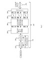
- Figure 1 depicts a block diagram of a GFDM transmitter 100 adapted for transmitting data bits through a channel according to the invention.
- a corresponding receiver 200 coupled to the transmission channel is depicted in figure 2 .
- the system schematically depicts a GFDM transmission system adapted and configured for implementing the invention, wherein figures provide an overview of the processing.
- the processing blocks of transmitter 100 may be all digital except for a digital-to-analog converter that converts the transmit signal from a digital representation to an analog signal prior to transmitting the signal by a transmit antenna and except for processing blocks arranged in the chain of processing blocks behind that converter.
- the receiver may comprise digital processing blocks only except for an analog-to-digital converter at the radio front end of the receiver and processing blocks arranged in the processing chain before said analog-to-digital converter such as a low-noise amplifier.
- the number of time slots per GFDM symbol is denoted by M, wherein an individual time slot is indexed by m with 0 ⁇ m ⁇ M - 1. Furthermore one GFDM symbol is transmitted using a number of K subcarriers, wherein an individual subcarrier is indexed by 0 ⁇ k ⁇ K - 1.
- a data source may provide a stream of data bits.
- the data bits are multiplexed by a serial-to-parallel converter 110 to a plurality of parallel substreams.
- the data bits are organized in M ⁇ K sets, wherein each set is mapped by a mapper 120 to a complex data symbol d k,m , wherein the mapping may be conventional.
- the mapping may be a conventional J-QAM mapping, wherein J is the order of the mapping.
- J is the order of the mapping.
- a group of data symbols assigned to a number of K subcarriers in one time slot m may be termed a subsymbol, thus there are K data symbols in the m -th subsymbol
- Each subsymbol consists of a number of N ⁇ K samples, wherein a sample is a complex value. Consequently, the mapping of sets of data bits to data symbols leads to a block structure of M ⁇ N samples.
- a transformation is applied all K data symbols of a subsymbol, i.e. all data symbols of an m -th time slot, that spreads the information of a single data symbol to the data symbols of all subcarriers of said m -th time slot.
- said transformation is applied to all subsymbols of the transmit symbol.
- the information of a single data symbol is spread to the data symbols of all subcarriers of the time slot corresponding to the one subsymbol. Since the transformation is applied to all data symbols of a time slot, each subcarrier carries at least a portion of the information of each other data symbol in said time slot.
- a Walsh-Hadamard matrix can be used as spreading matrix in block 130, wherein the Walsh-Hadamard transformation, WHT, requires K to be a power of two.
- the Walsh-Hadamard transformation matrix is a square matrix with dimension K ⁇ K wherein K is a power of 2.
- a Cazac matrix can be used as spreading matrix.
- the transformed samples are upsampled in block 140.
- the up-sampled samples i.e. the block of samples, are pulse shaped by g k,m [ n ] by a pulse-shaping filter block 150.
- a pulse-shaping filter block 150 For each subcarrier an individual pulse shaping filter may be provided, i.e. each of the K subcarriers may undergo an individual pulse shaping.
- the pulse-shaped samples of all K subcarriers then are summed in block 160 to form a single WHT-GFDM symbol x ⁇ [ n ], to which a cyclic prefix CP and/or a cyclic suffix CS can be added in block 170 in order to avoid inter-symbol interference, ISI.
- the symbol including the optional cyclic prefix and cyclic suffix i.e. the complex-valued samples reflecting the symbol are forwarded to a digital-to-analog converter and subsequent analog processing and amplifying stages, which are not shown in the figure, before it is transmitted, i.e. radiated, through a channel.
- Figure 2 depicts a receiver 200 adapted and configured for receiving and processing the signals transmitted by transmitter 100 as described above.
- Receiver 200 receives analog signals transmitted by transmitter 100, wherein the signals are attenuated and distorted by the channel.
- the received analog signals as received by an antenna may be amplified and processed before it is digitized, i.e. sampled and quantized thus producing complex-valued samples representing a received symbol.
- the samples of a received signal can be represented by a receive vector y e .
- the channel properties i.e. the channel impulse response CIR
- the vector may be synchronized in block 210, before samples of a cyclic prefix and cyclic suffix are removed in block 220 from the receive vector, wherein we assume that the cyclic prefix is larger than the channel length.
- signal represented by the samples of the receive vector is equalized in block 230 before being passed to detector 240.
- detector 240 can be any conventional detector, e.g. implementing a minimum mean squared error algorithm, MMSE, or a matched filter algorithm, MF, or in a preferred embodiment a zero-forcing algorithm, ZF.
- MMSE minimum mean squared error algorithm
- MF matched filter algorithm
- ZF zero-forcing algorithm
- Detector 240 outputs a plurality of subsymbols, wherein a subsymbol comprises transformed data symbols.
- the transformed subsymbols are forwarded to transformation block 250 where a transformation, i.e. an inverse of the transformation applied to the data symbols at the transmitter side, is applied to the symbols to reverse the transformation performed at the transmitter side.
- a transformation i.e. an inverse of the transformation applied to the data symbols at the transmitter side
- an optional narrow band interference detector and processing block 245 can be arranged between detector 240 and transformation block 250 for identifying subcarriers exhibiting excess narrow band interference as described in more detail below.
- the transformed data symbols then are then passed to a parallel-to-serial converter 260 that outputs a serial stream of symbols.
- the serial stream of symbols is then passed to a slicer 270 that processes the serial stream soft symbols, each soft symbols comprised of a data symbol and interference and noised added by the channel, determines the most probable data symbol corresponding to the soft symbol.
- Slicer 270 furthermore de-maps the determined data symbol, i.e. converts the serial stream of determined data symbol into a stream of bits thus outputting a stream of estimated data bits.
- a transmit symbol x ⁇ [ n ] can be generated at the transmitter side by performing matrix operations.
- g k , m n g ⁇ n - mN mod MN ⁇ e - j ⁇ 2 ⁇ ⁇ ⁇ k N ⁇ n with g k,m [ n ] being the impulse response, i.e. a filter for the k -th subcarrier of the m-th subsymbol.
- Transmit matrix A thus translates all M circularly shifted impulse responses to all K subcarriers.
- the transmitted signal is the sum of all symbols d j,m that have been Walsh-Hadamard-transformed by multiplication with ⁇ j,k and that have been filtered and up-converted to the respective k -th transmit frequency by multiplication with g m n ⁇ e - j ⁇ 2 ⁇ ⁇ ⁇ k N ⁇ n , wherein K is the number of subcarriers, M is the number of timeslots per GFDM transmit symbol, d j,m is the j -th data symbol of the m -th time-slot, ⁇ j,k is the coefficient of the j -th row and k -th column of the spreading matrix ⁇ , and g m [ n ] is the filter impulse response circularly shift of the mN samples and N is the number of samples per time-slot.
- each equivalent noise sample is a linear combination to the AWGN noise samples weighted by the channel frequency response and enhanced by the ZFR.
- each data symbol in the m -th time slot contains at least some information of each other data symbol of the m -th time slot.
- FSC frequency selective channel
- one subcarrier of the received plurality of subcarriers is found unusable, e.g. due to heavy interference by another signal or severely attenuated or erased
- the information carried by the unusable subcarrier is lost.
- the remaining subcarriers still carry a linear combination of all data symbols
- the information of all data symbols can be reconstructed by applying an inverse Walsh-Hadamard transformation to the remaining encoded received symbols. Accordingly, if a subset of subcarriers is severely attenuated by the channel, the information provided by the remaining subcarriers allows reconstruction of the entire information. Though a subset of subcarriers may be attenuated, the burst transmission is successful.
- the receiver may optionally comprise a narrow band interference detector and processing block 245 to clip subcarriers having an amplitude exceeding a predefined threshold value in order to prevent spreading of a heavily distorted subcarrier.
- the method performed at the receiver accordingly my optionally comprise the step of identifying subcarriers having an excess amplitude, i.e. subcarriers having an amplitude exceeding the predefined threshold, before applying the inverse of the transformation matrix.
- identification can be performed based on analyzing the noise distribution and noise variance of the subcarriers.
- the receiver may ignore signals carried by that subcarrier frequency in order to prevent spreading the heavily distorted subcarrier signals across other, non-infected subcarriers. In this way the method may prevent distortion, i.e. deterioration, of subcarrier signals that do not exceed the predefined threshold amplitude value.
- the described method can be used in channels that may exhibit notches, i.e. where subcarriers are heavily attenuated, but also where subcarriers may be deteriorated by a strong, narrowband and impulsive interferer.
- the receiver may adapted correspondingly, i.e. the receiver may comprise a corresponding narrow band interference detector and processing block 245 for identifying and - as the case may be - set a filter for ignoring signals of the identified subcarrier.
- the proposed application may enhance the reliability of data communication when using a frequency selective channel FSC, and particularly in single shot transmissions, when low out-of-band radiation is required and spectrum fragmentation is present.
- a Walsh-Hadamard transformation at the transmitter side is applied to data symbols.
- the transformation does not add any redundancy, consequently it does not affect the amount of data to be transmitted, but only increases the processing load both on the transmitter and on the receiver side of the transmission system by applying the Walsh-Hadamard transformation.
- bit error rate, BER performance of the afore-described transmission system over frequency selective channels, FSCs
- BER bit error rate
- H [ k ] is the flat channel frequency-response per subcarrier
- E b is the average energy per bit of the deployed J -QAM constellation
- N 0 is the noise spectral density.
- the performance gain of the Walsh-Hadamard-Transformation GFDM system depends on the channel frequency response. A slight or even no performance gain is expected for a flat channel, while a high performance gain is expected for FSCs with narrow notches, because in this case the data symbols can be successfully recovered even if a subset of subcarriers is severely attenuated by the channel.
- Figures 3a and 3b depict simulation curves of coded GFDM for comparison to other encoding schemes. Two codes are considered:
- LDPC is a powerful code that achieves the best performance of the presented cases.
- LDPC uses a long code word, and the iterative decoding process requires knowledge of the signal-to-noise ratio to compute the log-likelihood ratio (LLR). This process increases both the latency and the complexity of the receiver and might be inappropriate for low-latency scenarios, power-limited devices and single burst transmissions.
- LLR log-likelihood ratio
- the Reed-Solomon code is an interesting solution for avoiding burst errors.
- the non-iterative decoding process introduces small latency and it does not require knowledge of the channel parameters.
- the code word can be shortened to match the GFDM frame size, which is appropriate for burst transmissions.
- RS-GFDM outperforms WHT-GFDM for channel A, both schemes have similar performance when the channel frequency response has deep notches, as shown in fig. 3b .
Landscapes
- Engineering & Computer Science (AREA)
- Computer Networks & Wireless Communication (AREA)
- Signal Processing (AREA)
- Power Engineering (AREA)
- Mobile Radio Communication Systems (AREA)
Abstract
Description
- The invention relates to a radio transmission system using the generalized frequency divisional multiplexing (GFDM) method. In particular the invention relates to applying a Walsh-Hadamard transformation to a block of GFDM data symbols.
- The so-called GFDM system is a recent physical layer (PHY) scheme proposed to address the challenges for 5th generation cellular systems with opportunistic use of frequency spectrum and relaxed synchronization. The GFDM system provides a fast, flexible scalable and content aware physical layer scheme which at the same time is robust and reliable, while using vacant frequency bands, e.g. so-called TV white spaces. The basic GFDM system has been described in "GFDM - Generalized Frequency Division Multiplexing" by Fettweis et al., IEEE VTC spring 2009.
- Though the GFDM system shares some properties with well-known OFDM systems, there are significant differences. While both systems may divide an available frequency band into at least two adjoining sub-bands, the GFDM system may deploy individual transmission parameters for each of the at least two sub-bands while in OFDM the transmission parameters deployed in the sub-bands are similar or identical, i.e. uniform.
- In contrast thereto the Generalized Frequency Division Multiplexing, GFDM, is a multicarrier scheme that uses pulse-shaping per subcarrier to achieve low out-of-band emissions OOBE, i.e. low out-of-band interference. Typically a prototype filter is used to pulse-shape a number of K subcarriers, wherein the filter impulse response is circularly shifted by K samples to obtain the pulse-shape for each time slot. This technique is known as tail-biting and eliminates the filtering tails, thus allowing a block-based data structure, where a number of M · K data symbols are transmitted using a number of K subcarriers, each subcarrier carrying a number of M data symbols per block.
- The GFDM can be properly parameterized to address scenarios currently foreseen for the fifth generation of mobile communications, i.e. 5G. Single shot transmissions as required for the so-called tactile internet and random channel access as well as machine-to-machine communications and other low latency applications are challenging scenarios. In particular low-latency requirements prevent the use of retransmission protocols. Instead the data shall be reliably transmitted from source to sink using a single transmission burst, i.e. no retransmission, which at the same time avoids the use of long channel codes or interleavers. However, at least one drawback of using short single-shot transmission using GFDM occurs in frequency selective channels. Deep notches in the frequency response of a channel may lead to unrecoverable burst errors at the receiver side.
- The described method and system at least partially solves the above described problem in GFDM transmission systems.
- The proposed system will be understood more clearly when considering the figures wherein
- Fig. 1
- depicts a block diagram of a Walsh-Hadamard-GFDM transmitter;
- Fig. 2
- depicts a block diagram of a Walsh-Hadamard-GFDM receiver;
- Figs. 3a,b
- illustrate simulation curves of coded GFDM for comparison to other encoding schemes.
- The generalized frequency divisional multiplexing system defines a system architecture allowing opportunistically exploiting vacant frequency bands, for example TV white spaces, for wireless data communications. The system defines a concept for a physical layer and transmitters and receivers adapted and configured for using said physical layer concept as described below. Due to the opportunistic use of vacant frequency bands, i.e. bands that are not allocated for the GFDM system but currently are vacant, the signal generation in the GFDM system should ensure ultra-low out of band radiation to strictly avoid harmful interference to signals in adjoining frequency bands. Furthermore the receivers should exhibit high sensitivity in order to explore vacant frequency bands, i.e. to sense even very weak radio signals in the frequency bands that are candidates for use.
- Vacant frequency bands for use may be detected by any arbitrary method or device. In one embodiment the transmitter and/or the receiver of the GFDM system may cooperatively detect vacant frequency ranges by scanning frequencies for radio signals. In that case the scanned frequency obviously is in use and consequently cannot be used by GFDM system. If at least one of the transmitter and the receiver detects a vacant frequency band, the detecting station may inform its communication partner via another established communication link about said detected vacant frequency band. The partner station may then sense that band in order to ensure that there is no signal detectable. If both communication partner stations consider the frequency band as vacant said band may be used subsequently by the communication partners. In this way transmitter and receiver may try to detect and agree on using vacant frequency bands in addition to the established communication link.
- The described GFDM system may use a plurality of at least two frequency bands, wherein the carrier frequencies may have different bandwidths. In each of the two frequency bands a respective carrier frequency is individually modulated, i.e. the applied modulation scheme may vary from frequency band to frequency band, wherein some form of QAM modulation may be used.
- Note that in one embodiment the frequency bands may be divided by a frequency band occupied by another transmission, i.e. at least two frequency bands used by the described system are not adjacent, but separated by a frequency band occupied by another transmission. So in contrast to OFDM the described GFDM system does not rely on adjacent subcarriers.
- Each carrier is divided into time slots of equal duration, i.e. within each frequency band time slots of equal duration are defined. However, time slots of different frequency bands may differ in duration, i.e. symbol duration used for transmission in a first frequency band may differ from symbol duration used in a second frequency band. Consequently the number of time slots may vary between frequency bands. In frequency bands of larger bandwidth a higher number of time slots, i.e. shorter in duration, can be used within a transmit block than in frequency bands of smaller bandwidth. As a consequence a higher number of time slots are possible and used in a frequency band of larger bandwidth while achieving the same block size when combining said frequency band with a band of smaller bandwidth. Note that below described application of a transformation matrix to data symbols requires a common number of time slots, i.e. a common number of symbols. Consequently, below described transformation may be applied to data symbols in subcarriers having a common number of data symbols, i.e. time slots. However, in one embodiment a transmit symbol may comprise two groups of subcarriers, wherein each group of subcarriers exhibits a common number of time slots/data symbols, but wherein the groups exhibit different numbers of subcarriers, and wherein the groups require individual transform and modulation matrices.
-
Figure 1 depicts a block diagram of aGFDM transmitter 100 adapted for transmitting data bits through a channel according to the invention. Acorresponding receiver 200 coupled to the transmission channel is depicted infigure 2 . The system schematically depicts a GFDM transmission system adapted and configured for implementing the invention, wherein figures provide an overview of the processing. - The processing blocks of
transmitter 100 may be all digital except for a digital-to-analog converter that converts the transmit signal from a digital representation to an analog signal prior to transmitting the signal by a transmit antenna and except for processing blocks arranged in the chain of processing blocks behind that converter. Similarly the receiver may comprise digital processing blocks only except for an analog-to-digital converter at the radio front end of the receiver and processing blocks arranged in the processing chain before said analog-to-digital converter such as a low-noise amplifier. - Note that in
figure 1 the number of time slots per GFDM symbol is denoted by M, wherein an individual time slot is indexed by m with 0 ≤ m ≤ M - 1. Furthermore one GFDM symbol is transmitted using a number of K subcarriers, wherein an individual subcarrier is indexed by 0 ≤ k ≤ K - 1. - In one embodiment a data source may provide a stream of data bits. The data bits are multiplexed by a serial-to-
parallel converter 110 to a plurality of parallel substreams. The data bits are organized in M · K sets, wherein each set is mapped by amapper 120 to a complex data symbol dk,m , wherein the mapping may be conventional. In one embodiment the mapping may be a conventional J-QAM mapping, wherein J is the order of the mapping. Thus data bits are mapped to a number of M · K data symbols dk,m . Note that in the following a group of data symbols assigned to a number of K subcarriers in one time slot m may be termed a subsymbol, thus there are K data symbols in the m-th subsymbol Each subsymbol consists of a number of N ≥ K samples, wherein a sample is a complex value. Consequently, the mapping of sets of data bits to data symbols leads to a block structure of M · N samples. - Then in block 130 a transformation is applied all K data symbols of a subsymbol, i.e. all data symbols of an m-th time slot, that spreads the information of a single data symbol to the data symbols of all subcarriers of said m-th time slot. In particular said transformation is applied to all subsymbols of the transmit symbol. As a consequence the information of a single data symbol is spread to the data symbols of all subcarriers of the time slot corresponding to the one subsymbol. Since the transformation is applied to all data symbols of a time slot, each subcarrier carries at least a portion of the information of each other data symbol in said time slot.
- Said spreading of information can be effected by applying a matrix transformation using a spreading matrix Ω for which the condition Ω×ΩH= I holds, wherein I is the identity matrix.
- In one embodiment a Walsh-Hadamard matrix can be used as spreading matrix in
block 130, wherein the Walsh-Hadamard transformation, WHT, requires K to be a power of two. As a consequence the Walsh-Hadamard transformation matrix is a square matrix with dimension K × K wherein K is a power of 2. In an alternative embodiment a Cazac matrix can be used as spreading matrix. - In the next processing step the transformed samples are upsampled in
block 140. - The up-sampled samples, i.e. the block of samples, are pulse shaped by gk,m [n] by a pulse-shaping
filter block 150. Note that in one embodiment for each subcarrier an individual pulse shaping filter may be provided, i.e. each of the K subcarriers may undergo an individual pulse shaping. - The pulse-shaped samples of all K subcarriers then are summed in
block 160 to form a single WHT-GFDM symbol x Ω [n], to which a cyclic prefix CP and/or a cyclic suffix CS can be added inblock 170 in order to avoid inter-symbol interference, ISI. - Lastly the symbol including the optional cyclic prefix and cyclic suffix, i.e. the complex-valued samples reflecting the symbol are forwarded to a digital-to-analog converter and subsequent analog processing and amplifying stages, which are not shown in the figure, before it is transmitted, i.e. radiated, through a channel.
-
Figure 2 depicts areceiver 200 adapted and configured for receiving and processing the signals transmitted bytransmitter 100 as described above. -
Receiver 200 receives analog signals transmitted bytransmitter 100, wherein the signals are attenuated and distorted by the channel. The received analog signals as received by an antenna may be amplified and processed before it is digitized, i.e. sampled and quantized thus producing complex-valued samples representing a received symbol. The samples of a received signal can be represented by a receive vector ye . - Based on the receive vector the channel properties, i.e. the channel impulse response CIR, may be estimated and the vector may be synchronized in
block 210, before samples of a cyclic prefix and cyclic suffix are removed inblock 220 from the receive vector, wherein we assume that the cyclic prefix is larger than the channel length. Furthermore signal represented by the samples of the receive vector is equalized inblock 230 before being passed todetector 240. - Basically
detector 240 can be any conventional detector, e.g. implementing a minimum mean squared error algorithm, MMSE, or a matched filter algorithm, MF, or in a preferred embodiment a zero-forcing algorithm, ZF. -
Detector 240 outputs a plurality of subsymbols, wherein a subsymbol comprises transformed data symbols. The transformed subsymbols are forwarded to transformation block 250 where a transformation, i.e. an inverse of the transformation applied to the data symbols at the transmitter side, is applied to the symbols to reverse the transformation performed at the transmitter side. Note that an optional narrow band interference detector andprocessing block 245 can be arranged betweendetector 240 andtransformation block 250 for identifying subcarriers exhibiting excess narrow band interference as described in more detail below. - The transformed data symbols then are then passed to a parallel-to-
serial converter 260 that outputs a serial stream of symbols. - The serial stream of symbols is then passed to a
slicer 270 that processes the serial stream soft symbols, each soft symbols comprised of a data symbol and interference and noised added by the channel, determines the most probable data symbol corresponding to the soft symbol.Slicer 270 furthermore de-maps the determined data symbol, i.e. converts the serial stream of determined data symbol into a stream of bits thus outputting a stream of estimated data bits. - A transmit symbol x Ω [n] can be generated at the transmitter side by performing matrix operations. The subsymbol c m transmitted in the m-th time slot, i.e. the m-th subsymbol consisting of the data symbols assigned to all K subcarriers, can be calculated as

wherein m is the index of a time slot, K is the number of subcarriers and wherein Ω K is the transform matrix, i.e. the spreading matrix, wherein in this exemplifying calculation a Walsh-Hadamard transformation matrix is considered:
wherein Ω1 = 1. - Transmission matrix A is defined by

where
with gk,m [n] being the impulse response, i.e. a filter for the k-th subcarrier of the m-th subsymbol. Transmit matrix A thus translates all M circularly shifted impulse responses to all K subcarriers. - And with the concatenation of a number of M Walsh-Hadamard-transformed sample vectors

the transmit vector can be written in matrix form as
- Thus the transmitted signal is


- The processing at the receiver side also can be described in mathematical terms. After synchronization, equalization, and removal of a cyclic prefix CP and/or a cyclic suffix CS a received vector of samples y is
 denotes the circular convolution.
- Under the assumption that the channel impulse response is known at the receiver side and the cyclic prefix CP is larger than the channel length, frequency domain equalization can be applied, yielding

-
Decoder 240, which in one particular embodiment may be a ZFR, then may calculate the received transformed sample vector as

- The recovered data symbols for each time-slot thus are given by

where w em is the equivalent noise vector containing the samples corresponding to the m-th subsymbol. Note that because the transformation combines the noise samples without changing the variance, each equivalent noise sample is a linear combination to the AWGN noise samples weighted by the channel frequency response and enhanced by the ZFR. - So by applying a transformation, e.g. in one embodiment by applying a Walsh-Hadamard matrix or a Cazac matrix or any other matrix where rows and columns are orthogonal, to the data symbols of all K subcarriers of one time slot m, the information of each data symbol is spread to all data symbols of said m-th timeslot. In other words the transformed data symbols of the m-th timeslot are a linear combination of K data symbols of the m-th time slot. As a consequence each data symbol in the m-th time slot contains at least some information of each other data symbol of the m-th time slot.
- In case of a frequency selective channel, FSC, i.e. one subcarrier of the received plurality of subcarriers is found unusable, e.g. due to heavy interference by another signal or severely attenuated or erased, the information carried by the unusable subcarrier is lost. However, since the remaining subcarriers still carry a linear combination of all data symbols, the information of all data symbols can be reconstructed by applying an inverse Walsh-Hadamard transformation to the remaining encoded received symbols. Accordingly, if a subset of subcarriers is severely attenuated by the channel, the information provided by the remaining subcarriers allows reconstruction of the entire information. Though a subset of subcarriers may be attenuated, the burst transmission is successful.
- In one embodiment the receiver may optionally comprise a narrow band interference detector and
processing block 245 to clip subcarriers having an amplitude exceeding a predefined threshold value in order to prevent spreading of a heavily distorted subcarrier. Subcarriers showing an excess amplitude, i.e. an amplitude significantly higher than an average expected, most probably have been distorted by a narrow band interference, i.e. the payload signal of the subcarrier is overlaid by a strong interfering signal. If such a distorted subcarrier would be processed using the inverse transformation matrix, then the strong interfering signal would be spread across all healthy, i.e. non- or less-interfered subcarriers. The method performed at the receiver accordingly my optionally comprise the step of identifying subcarriers having an excess amplitude, i.e. subcarriers having an amplitude exceeding the predefined threshold, before applying the inverse of the transformation matrix. In one embodiment that identification can be performed based on analyzing the noise distribution and noise variance of the subcarriers. In case a subcarrier of excess amplitude is identified, the receiver may ignore signals carried by that subcarrier frequency in order to prevent spreading the heavily distorted subcarrier signals across other, non-infected subcarriers. In this way the method may prevent distortion, i.e. deterioration, of subcarrier signals that do not exceed the predefined threshold amplitude value. As a consequence the described method can be used in channels that may exhibit notches, i.e. where subcarriers are heavily attenuated, but also where subcarriers may be deteriorated by a strong, narrowband and impulsive interferer. The receiver may adapted correspondingly, i.e. the receiver may comprise a corresponding narrow band interference detector andprocessing block 245 for identifying and - as the case may be - set a filter for ignoring signals of the identified subcarrier. - As a consequence the proposed application may enhance the reliability of data communication when using a frequency selective channel FSC, and particularly in single shot transmissions, when low out-of-band radiation is required and spectrum fragmentation is present.
- Further note that a Walsh-Hadamard transformation at the transmitter side is applied to data symbols. The transformation does not add any redundancy, consequently it does not affect the amount of data to be transmitted, but only increases the processing load both on the transmitter and on the receiver side of the transmission system by applying the Walsh-Hadamard transformation.
- The bit error rate, BER, performance of the afore-described transmission system over frequency selective channels, FSCs, can be estimated as an average of the performance of each subcarrier considering the corresponding channel frequency response. Therefore the bit error probability can be approximated by

where H[k] is the flat channel frequency-response per subcarrier, Eb is the average energy per bit of the deployed J-QAM constellation, and N 0 is the noise spectral density. - Considering now that the equivalent channel after the inverse Walsh-Hadamard-Transformation has a flat frequency response

above given bit error probability approximation can be used to estimate the bit error rate, BER, of the Walsh-Hadamard-Transformation GFDM over frequency selective channels, FSCs. Since the channel is flat, all subcarriers present the same performance, thus
- Based on this bit probability one can conclude that the performance gain of the Walsh-Hadamard-Transformation GFDM system depends on the channel frequency response. A slight or even no performance gain is expected for a flat channel, while a high performance gain is expected for FSCs with narrow notches, because in this case the data symbols can be successfully recovered even if a subset of subcarriers is severely attenuated by the channel.
-
Figures 3a and 3b depict simulation curves of coded GFDM for comparison to other encoding schemes. Two codes are considered: - i) a low-density parity-check, LDPC, code with a length of 64,800 bits and a code rate of ¾ and
- ii) a Reed-Solomon, RS, code (224, 204).
- LDPC is a powerful code that achieves the best performance of the presented cases. However, LDPC uses a long code word, and the iterative decoding process requires knowledge of the signal-to-noise ratio to compute the log-likelihood ratio (LLR). This process increases both the latency and the complexity of the receiver and might be inappropriate for low-latency scenarios, power-limited devices and single burst transmissions. The Reed-Solomon code is an interesting solution for avoiding burst errors. The non-iterative decoding process introduces small latency and it does not require knowledge of the channel parameters. The code word can be shortened to match the GFDM frame size, which is appropriate for burst transmissions. However, energy limited low-cost devices might not be able to afford the complexity of the RS decode. Although RS-GFDM outperforms WHT-GFDM for channel A, both schemes have similar performance when the channel frequency response has deep notches, as shown in
fig. 3b .
Claims (17)
- A method for transmitting digital data in a transmit symbol using a frequency divisional multiplexing, GFDM, system,
said transmit symbol comprising a plurality of data symbols assigned to at least two subcarriers, the method comprising the steps of- mapping a plurality of data bits to data symbols and assigning data symbols to the at least two subcarriers, and- spreading the information of each data symbol of a time slot of the transmit symbol across the data symbols of each subcarrier of said time slot, and- appending at least one of a cyclic prefix or a cyclic suffix to the transmit symbol, and- transmitting the transmit symbol and the cyclic prefix and/or the cyclic suffix. - The method of claim 1 wherein the step of spreading the information of each data symbol of one time slot of the transmit symbol to the data symbols of each subcarrier of said time slot comprises applying a transformation matrix to all data symbols of said time slot, wherein the rows and columns of the transformation matrix are orthogonal.
- The method of claim 2 wherein the transformation matrix is a Walsh-Hadamard matrix or a Cazac matrix.
- The method of any preceding claim wherein the at least two subcarriers are separated by another frequency band occupied by another transmis-sion.
- The method of any preceding claim wherein the step of spreading the information of each data symbol of a time slot of the transmit symbol to the data symbols of each subcarrier of said time slot is performed for each time slot of the transmit symbol.
- A method for receiving digital data using frequency divisional multiplexing, GFDM, system
comprising the steps of:- receiving a frequency divisional multiplex signal representing a transmit symbol, said transmit symbol comprising a plurality of data symbols assigned to at least two subcarriers, and- removing at least one of a cyclic prefix or a cyclic suffix from the transmit symbol- de-spreading the information of each received data symbol of a time slot of the transmit symbol to the data symbols of each subcarrier of said time slot by applying an inverse of the transformation applied at the transmitter, and- decoding the data symbols. - The method of claim 6 wherein the step of applying an inverse of the transformation applied to data symbols at the transmitter comprises applying an inverse of corresponding transformation matrix wherein rows and columns of the transformation matrix are orthogonal.
- The method of any of claims 6-7 wherein the transformation matrix is an inverse of a Walsh-Hadamard transformation matrix or an inverse of a corresponding Cazac transformation matrix.
- The method of any of claims 6-8 wherein the at least two subcarriers are separated by another frequency band occupied by another transmission.
- The method of any of claims 6-9 further comprising the step of identifying at least one subcarrier having an amplitude exceeding a predefined threshold value before performing the step of de-spreading of received data symbols and ignoring said identified subcarrier in the step of de-spreading.
- A transmitter adapted and configured for transmitting digital data using a frequency divisional multiplexing method, GFDM, wherein a transmit symbol comprises a plurality of data symbols assigned to at least two subcarriers, the method comprising the steps of.- mapping a plurality of data bits to data symbols and assigning data symbols to the at least two subcarriers, and- spreading the information of each data symbol of a time slot of the transmit symbol to the data symbols of each subcarrier of said time slot, and- appending at least one of a cyclic prefix or a cyclic suffix to the transmit symbol, and- transmitting the transmit symbol and the cyclic prefix and/or the cyclic suffix.
- The transmitter of claim 11 wherein the step of spreading the information of each data symbol of one time slot of the transmit symbol to the data symbols of each subcarrier of said time slot comprises applying a transformation matrix to all data symbols of said time slot, wherein the rows and columns of the transformation matrix are orthogonal.
- The transmitter of claims 11-12 wherein the transformation matrix is a Walsh-Hadamard matrix or a Cazac matrix.
- A receiver for receiving digital data using a frequency divisional multiplexing, GFDM, method, wherein a received GFDM signal represents a transmit symbol, said transmit symbol comprising a plurality of data symbols assigned to at least two subcarriers, said receiver being adapted for- receiving a frequency divisional multiplex signal representing a transmit symbol, said transmit symbol comprising a plurality of data symbols assigned to at least two subcarriers, and- removing at least one of a cyclic prefix or a cyclic suffix from the transmit symbol- de-spreading the information of each received data symbol of a time slot of the transmit symbol to the data symbols of each subcarrier of said time slot by applying an inverse of the transformation applied at the transmitter, and- decoding the data symbols.
- The receiver of any of claim 14 wherein the step of applying an inverse of the transformation applied to data symbols at the transmitter comprises applying an inverse of corresponding transformation matrix wherein rows and columns of the transformation matrix are orthogonal.
- The receiver of any of claims 14-15 wherein the transformation matrix is an inverse of a Walsh-Hadamard transformation matrix or an inverse of a corresponding Cazac transformation matrix.
- The receiver of any of claims 14-16 further adapted for performing the step of identifying at least one subcarrier having an amplitude exceeding a predefined threshold value before performing the step of de-spreading of received data symbols and ignoring said identified subcarrier in the step of de-spreading.
Priority Applications (2)
| Application Number | Priority Date | Filing Date | Title |
|---|---|---|---|
| EP14158393.0A EP2916506B1 (en) | 2014-03-07 | 2014-03-07 | Walsh-Hadamard transformed GFDM radio transmission |
| US14/640,331 US9680540B2 (en) | 2014-03-07 | 2015-03-06 | Walsh-hadamard transformed GFDM radio transmission |
Applications Claiming Priority (1)
| Application Number | Priority Date | Filing Date | Title |
|---|---|---|---|
| EP14158393.0A EP2916506B1 (en) | 2014-03-07 | 2014-03-07 | Walsh-Hadamard transformed GFDM radio transmission |
Publications (2)
| Publication Number | Publication Date |
|---|---|
| EP2916506A1 true EP2916506A1 (en) | 2015-09-09 |
| EP2916506B1 EP2916506B1 (en) | 2019-07-31 |
Family
ID=50241162
Family Applications (1)
| Application Number | Title | Priority Date | Filing Date |
|---|---|---|---|
| EP14158393.0A Active EP2916506B1 (en) | 2014-03-07 | 2014-03-07 | Walsh-Hadamard transformed GFDM radio transmission |
Country Status (2)
| Country | Link |
|---|---|
| US (1) | US9680540B2 (en) |
| EP (1) | EP2916506B1 (en) |
Cited By (2)
| Publication number | Priority date | Publication date | Assignee | Title |
|---|---|---|---|---|
| CN106330277A (en) * | 2016-08-26 | 2017-01-11 | 西安电子科技大学 | Correlation rotation precoding method applied to GFDM communication system |
| CN108199988A (en) * | 2018-01-02 | 2018-06-22 | 天津大学 | Frequency domain GFDM low complex degree least mean-square error method of reseptances and receiver |
Families Citing this family (8)
| Publication number | Priority date | Publication date | Assignee | Title |
|---|---|---|---|---|
| CN107370704A (en) * | 2016-05-13 | 2017-11-21 | 财团法人工业技术研究院 | Wireless communication device and wireless signal generating method |
| US9973364B2 (en) * | 2016-06-27 | 2018-05-15 | Intel IP Corporation | Generalized frequency division multiplexing (GFDM) frame strucutre for IEEE 802.11AY |
| WO2018137231A1 (en) * | 2017-01-26 | 2018-08-02 | Qualcomm Incorporated | Broadcast channel encoding and decoding |
| KR101962273B1 (en) * | 2017-02-07 | 2019-07-17 | 고려대학교 산학협력단 | Apparatus and method for interference cancellation robust to carrier frequency offset in wireless communication system |
| CN107682296B (en) * | 2017-08-17 | 2020-06-30 | 天津大学 | MMSE (minimum mean square error) receiving method and device suitable for GFDM (ground fault frequency division multiplexing) system of FSC (frequency selective modulation) |
| WO2020113463A1 (en) * | 2018-12-05 | 2020-06-11 | 唐山照澜海洋科技有限公司 | 5g multi-carrier spread spectrum underwater acoustic communication method |
| US11956111B2 (en) * | 2020-02-14 | 2024-04-09 | Huawei Technologies Co., Ltd. | Multi-rate crest factor reduction |
| CN116112101B (en) * | 2022-12-27 | 2026-01-16 | 深圳市通用测试系统有限公司 | Air radiation test system, method and tester for wireless equipment |
Citations (3)
| Publication number | Priority date | Publication date | Assignee | Title |
|---|---|---|---|---|
| EP2200244A1 (en) * | 2008-12-18 | 2010-06-23 | Vodafone Holding GmbH | Method and apparatus for multi-carrier frequency division multiplexing transmission |
| EP2348655A1 (en) * | 2008-12-19 | 2011-07-27 | Nippon Telegraph And Telephone Corporation | Wireless communication system and method of communicating wirelessly |
| EP2608474A1 (en) * | 2011-12-23 | 2013-06-26 | Vodafone Holding GmbH | Method and transmitter/receiver for data transmission with flexible exploitation of time and frequency diversity |
Family Cites Families (3)
| Publication number | Priority date | Publication date | Assignee | Title |
|---|---|---|---|---|
| EP2033393B1 (en) * | 2006-06-14 | 2014-01-22 | Agere Systems Inc. | Orthogonal frequency division multiplexing using subsymbol processing |
| US7809046B2 (en) * | 2007-10-03 | 2010-10-05 | Agere Systems Inc. | Timing-offset estimation in modulated signals using weighted correlation values |
| US9379917B2 (en) * | 2013-09-09 | 2016-06-28 | Huawei Technologies Co., Ltd. | System and method for channel estimation for generalized frequency division multiplexing (GFDM) |
-
2014
- 2014-03-07 EP EP14158393.0A patent/EP2916506B1/en active Active
-
2015
- 2015-03-06 US US14/640,331 patent/US9680540B2/en active Active
Patent Citations (3)
| Publication number | Priority date | Publication date | Assignee | Title |
|---|---|---|---|---|
| EP2200244A1 (en) * | 2008-12-18 | 2010-06-23 | Vodafone Holding GmbH | Method and apparatus for multi-carrier frequency division multiplexing transmission |
| EP2348655A1 (en) * | 2008-12-19 | 2011-07-27 | Nippon Telegraph And Telephone Corporation | Wireless communication system and method of communicating wirelessly |
| EP2608474A1 (en) * | 2011-12-23 | 2013-06-26 | Vodafone Holding GmbH | Method and transmitter/receiver for data transmission with flexible exploitation of time and frequency diversity |
Non-Patent Citations (4)
| Title |
|---|
| BIANCHI T ET AL: "Analysis of the effects of carrier frequency offset on filterbank-based MC-CDMA", GLOBAL TELECOMMUNICATIONS CONFERENCE, 2004. GLOBECOM '04. IEEE DALLAS, TX, USA 29 NOV.-3 DEC., 2004, PISCATAWAY, NJ, USA,IEEE, PISCATAWAY, NJ, USA, vol. 4, 29 November 2004 (2004-11-29), pages 2520 - 2524, XP010757981, ISBN: 978-0-7803-8794-2, DOI: 10.1109/GLOCOM.2004.1378460 * |
| BRANDES S ET AL: "Compensation of the Impact of Interference Mitigation by Pulse Blanking in OFDM Systems", GLOBAL TELECOMMUNICATIONS CONFERENCE, 2009. GLOBECOM 2009. IEEE, IEEE, PISCATAWAY, NJ, USA, 30 November 2009 (2009-11-30), pages 1 - 6, XP031646222, ISBN: 978-1-4244-4148-8 * |
| FETTWEIS ET AL.: "GFDM - Generalized Frequency Division Multiplexing", IEEE VTC SPRING, 2009 |
| RIERA-PALOU F ET AL: "On the design of uplink and downlink group-orthogonal multicarrier wireless systems", IEEE TRANSACTIONS ON COMMUNICATIONS, IEEE SERVICE CENTER, PISCATAWAY, NJ. USA, vol. 56, no. 10, 10 October 2008 (2008-10-10), pages 1656 - 1665, XP011236197, ISSN: 0090-6778, DOI: 10.1109/TCOMM.2008.060497 * |
Cited By (4)
| Publication number | Priority date | Publication date | Assignee | Title |
|---|---|---|---|---|
| CN106330277A (en) * | 2016-08-26 | 2017-01-11 | 西安电子科技大学 | Correlation rotation precoding method applied to GFDM communication system |
| CN106330277B (en) * | 2016-08-26 | 2019-06-21 | 西安电子科技大学 | Correlation Rotation Precoding Method Applied in GFDM Communication System |
| CN108199988A (en) * | 2018-01-02 | 2018-06-22 | 天津大学 | Frequency domain GFDM low complex degree least mean-square error method of reseptances and receiver |
| CN108199988B (en) * | 2018-01-02 | 2021-06-04 | 天津大学 | Frequency Domain GFDM Low Complexity Minimum Mean Square Error Receiving Method and Receiver |
Also Published As
| Publication number | Publication date |
|---|---|
| US9680540B2 (en) | 2017-06-13 |
| US20160373172A1 (en) | 2016-12-22 |
| EP2916506B1 (en) | 2019-07-31 |
Similar Documents
| Publication | Publication Date | Title |
|---|---|---|
| EP2916506B1 (en) | Walsh-Hadamard transformed GFDM radio transmission | |
| US8947996B2 (en) | Offset modulation orthogonal frequency division multiplexing (OFDM) and multi-access transmission method with cyclic prefix (CP) | |
| KR100811907B1 (en) | Frequency-hopped ifdma communication system | |
| US10938876B2 (en) | Method and system for low data rate transmission | |
| US8582622B2 (en) | Spread-spectrum coding of data bursts | |
| US7672384B2 (en) | Bandwidth and power efficient multicarrier multiple access | |
| RU2428796C2 (en) | Methods and devices to increase efficiency and to make it possible to quickly decode transfers with multiple code units | |
| US7701839B2 (en) | Method and system for multirate multiuser modulation | |
| US10250400B2 (en) | Apparatus for transmitting broadcast signals, apparatus for receiving broadcast signals, method for transmitting broadcast signals and method for receiving broadcast signals | |
| CN101803235B (en) | Transmission method of control channel format indicator/physical control format indicator channel in wireless communication system | |
| Matthé et al. | Space-time coding for generalized frequency division multiplexing | |
| RU2617993C1 (en) | Device for transmitting broadcast signals, device for receiving broadcast signals, method for transmitting broadcast signals and method for receiving broadcast signals | |
| US11563608B2 (en) | Method and apparatus for signal modulation and demodulation in wireless communication system | |
| US20060250944A1 (en) | Apparatus and method for transmitting bit-interleaved coded modulation signals in an orthogonal frequency division multiplexing system | |
| EP3518484A1 (en) | Transmission device, reception device, transmission method and reception method | |
| Xu et al. | Bandwidth compressed carrier aggregation | |
| EP2978224A1 (en) | Broadcast signal transmitting method, broadcast signal receiving method, broadcast signal transmitting apparatus, and broadcast signal receiving apparatus | |
| US7889806B2 (en) | Method and apparatus to improve performance in a multicarrier MIMO channel using the hadamard transform | |
| US20100189092A1 (en) | Transmitter, transmitting method, receiver, and receiving method | |
| WO2009043311A1 (en) | Time-frequency spreading method and apparatus in ofdma system | |
| Chaturvedi et al. | Performance Analysis for Different Interleavers in Various Modulation Schemes with OFDM over an AWGN Channel | |
| CN102916924B (en) | The offset modulation multi-carrier frequency division multiple access transmission method of BREATHABLE BANDWIDTH | |
| Telagam et al. | Ber analysis of concatenated levels of encoding in GFDM system using labview | |
| Kumar et al. | BER analysis of GFDM system augmented with SC diversity combining scheme for diverse Pulse Shaping Filters | |
| KR102332508B1 (en) | Signal transmission method of space-frequency block coded single side band single carrier frequency division multiple access system |
Legal Events
| Date | Code | Title | Description |
|---|---|---|---|
| PUAI | Public reference made under article 153(3) epc to a published international application that has entered the european phase |
Free format text: ORIGINAL CODE: 0009012 |
|
| AK | Designated contracting states |
Kind code of ref document: A1 Designated state(s): AL AT BE BG CH CY CZ DE DK EE ES FI FR GB GR HR HU IE IS IT LI LT LU LV MC MK MT NL NO PL PT RO RS SE SI SK SM TR |
|
| AX | Request for extension of the european patent |
Extension state: BA ME |
|
| 17P | Request for examination filed |
Effective date: 20160111 |
|
| RBV | Designated contracting states (corrected) |
Designated state(s): AL AT BE BG CH CY CZ DE DK EE ES FI FR GB GR HR HU IE IS IT LI LT LU LV MC MK MT NL NO PL PT RO RS SE SI SK SM TR |
|
| STAA | Information on the status of an ep patent application or granted ep patent |
Free format text: STATUS: EXAMINATION IS IN PROGRESS |
|
| 17Q | First examination report despatched |
Effective date: 20180622 |
|
| REG | Reference to a national code |
Ref country code: DE Ref legal event code: R079 Ref document number: 602014050748 Country of ref document: DE Free format text: PREVIOUS MAIN CLASS: H04L0027260000 Ipc: H04L0001000000 |
|
| GRAP | Despatch of communication of intention to grant a patent |
Free format text: ORIGINAL CODE: EPIDOSNIGR1 |
|
| STAA | Information on the status of an ep patent application or granted ep patent |
Free format text: STATUS: GRANT OF PATENT IS INTENDED |
|
| RIC1 | Information provided on ipc code assigned before grant |
Ipc: H04L 27/26 20060101ALI20190313BHEP Ipc: H04L 1/00 20060101AFI20190313BHEP |
|
| INTG | Intention to grant announced |
Effective date: 20190410 |
|
| GRAS | Grant fee paid |
Free format text: ORIGINAL CODE: EPIDOSNIGR3 |
|
| GRAA | (expected) grant |
Free format text: ORIGINAL CODE: 0009210 |
|
| STAA | Information on the status of an ep patent application or granted ep patent |
Free format text: STATUS: THE PATENT HAS BEEN GRANTED |
|
| AK | Designated contracting states |
Kind code of ref document: B1 Designated state(s): AL AT BE BG CH CY CZ DE DK EE ES FI FR GB GR HR HU IE IS IT LI LT LU LV MC MK MT NL NO PL PT RO RS SE SI SK SM TR |
|
| REG | Reference to a national code |
Ref country code: CH Ref legal event code: EP Ref country code: GB Ref legal event code: FG4D |
|
| REG | Reference to a national code |
Ref country code: AT Ref legal event code: REF Ref document number: 1162096 Country of ref document: AT Kind code of ref document: T Effective date: 20190815 |
|
| REG | Reference to a national code |
Ref country code: IE Ref legal event code: FG4D |
|
| REG | Reference to a national code |
Ref country code: DE Ref legal event code: R096 Ref document number: 602014050748 Country of ref document: DE |
|
| REG | Reference to a national code |
Ref country code: NL Ref legal event code: MP Effective date: 20190731 |
|
| REG | Reference to a national code |
Ref country code: LT Ref legal event code: MG4D |
|
| REG | Reference to a national code |
Ref country code: AT Ref legal event code: MK05 Ref document number: 1162096 Country of ref document: AT Kind code of ref document: T Effective date: 20190731 |
|
| PG25 | Lapsed in a contracting state [announced via postgrant information from national office to epo] |
Ref country code: BG Free format text: LAPSE BECAUSE OF FAILURE TO SUBMIT A TRANSLATION OF THE DESCRIPTION OR TO PAY THE FEE WITHIN THE PRESCRIBED TIME-LIMIT Effective date: 20191031 Ref country code: SE Free format text: LAPSE BECAUSE OF FAILURE TO SUBMIT A TRANSLATION OF THE DESCRIPTION OR TO PAY THE FEE WITHIN THE PRESCRIBED TIME-LIMIT Effective date: 20190731 Ref country code: NL Free format text: LAPSE BECAUSE OF FAILURE TO SUBMIT A TRANSLATION OF THE DESCRIPTION OR TO PAY THE FEE WITHIN THE PRESCRIBED TIME-LIMIT Effective date: 20190731 Ref country code: AT Free format text: LAPSE BECAUSE OF FAILURE TO SUBMIT A TRANSLATION OF THE DESCRIPTION OR TO PAY THE FEE WITHIN THE PRESCRIBED TIME-LIMIT Effective date: 20190731 Ref country code: NO Free format text: LAPSE BECAUSE OF FAILURE TO SUBMIT A TRANSLATION OF THE DESCRIPTION OR TO PAY THE FEE WITHIN THE PRESCRIBED TIME-LIMIT Effective date: 20191031 Ref country code: LT Free format text: LAPSE BECAUSE OF FAILURE TO SUBMIT A TRANSLATION OF THE DESCRIPTION OR TO PAY THE FEE WITHIN THE PRESCRIBED TIME-LIMIT Effective date: 20190731 Ref country code: HR Free format text: LAPSE BECAUSE OF FAILURE TO SUBMIT A TRANSLATION OF THE DESCRIPTION OR TO PAY THE FEE WITHIN THE PRESCRIBED TIME-LIMIT Effective date: 20190731 Ref country code: FI Free format text: LAPSE BECAUSE OF FAILURE TO SUBMIT A TRANSLATION OF THE DESCRIPTION OR TO PAY THE FEE WITHIN THE PRESCRIBED TIME-LIMIT Effective date: 20190731 Ref country code: PT Free format text: LAPSE BECAUSE OF FAILURE TO SUBMIT A TRANSLATION OF THE DESCRIPTION OR TO PAY THE FEE WITHIN THE PRESCRIBED TIME-LIMIT Effective date: 20191202 |
|
| PG25 | Lapsed in a contracting state [announced via postgrant information from national office to epo] |
Ref country code: ES Free format text: LAPSE BECAUSE OF FAILURE TO SUBMIT A TRANSLATION OF THE DESCRIPTION OR TO PAY THE FEE WITHIN THE PRESCRIBED TIME-LIMIT Effective date: 20190731 Ref country code: AL Free format text: LAPSE BECAUSE OF FAILURE TO SUBMIT A TRANSLATION OF THE DESCRIPTION OR TO PAY THE FEE WITHIN THE PRESCRIBED TIME-LIMIT Effective date: 20190731 Ref country code: LV Free format text: LAPSE BECAUSE OF FAILURE TO SUBMIT A TRANSLATION OF THE DESCRIPTION OR TO PAY THE FEE WITHIN THE PRESCRIBED TIME-LIMIT Effective date: 20190731 Ref country code: GR Free format text: LAPSE BECAUSE OF FAILURE TO SUBMIT A TRANSLATION OF THE DESCRIPTION OR TO PAY THE FEE WITHIN THE PRESCRIBED TIME-LIMIT Effective date: 20191101 Ref country code: IS Free format text: LAPSE BECAUSE OF FAILURE TO SUBMIT A TRANSLATION OF THE DESCRIPTION OR TO PAY THE FEE WITHIN THE PRESCRIBED TIME-LIMIT Effective date: 20191130 Ref country code: RS Free format text: LAPSE BECAUSE OF FAILURE TO SUBMIT A TRANSLATION OF THE DESCRIPTION OR TO PAY THE FEE WITHIN THE PRESCRIBED TIME-LIMIT Effective date: 20190731 |
|
| PG25 | Lapsed in a contracting state [announced via postgrant information from national office to epo] |
Ref country code: TR Free format text: LAPSE BECAUSE OF FAILURE TO SUBMIT A TRANSLATION OF THE DESCRIPTION OR TO PAY THE FEE WITHIN THE PRESCRIBED TIME-LIMIT Effective date: 20190731 |
|
| PG25 | Lapsed in a contracting state [announced via postgrant information from national office to epo] |
Ref country code: RO Free format text: LAPSE BECAUSE OF FAILURE TO SUBMIT A TRANSLATION OF THE DESCRIPTION OR TO PAY THE FEE WITHIN THE PRESCRIBED TIME-LIMIT Effective date: 20190731 Ref country code: EE Free format text: LAPSE BECAUSE OF FAILURE TO SUBMIT A TRANSLATION OF THE DESCRIPTION OR TO PAY THE FEE WITHIN THE PRESCRIBED TIME-LIMIT Effective date: 20190731 Ref country code: IT Free format text: LAPSE BECAUSE OF FAILURE TO SUBMIT A TRANSLATION OF THE DESCRIPTION OR TO PAY THE FEE WITHIN THE PRESCRIBED TIME-LIMIT Effective date: 20190731 Ref country code: PL Free format text: LAPSE BECAUSE OF FAILURE TO SUBMIT A TRANSLATION OF THE DESCRIPTION OR TO PAY THE FEE WITHIN THE PRESCRIBED TIME-LIMIT Effective date: 20190731 Ref country code: DK Free format text: LAPSE BECAUSE OF FAILURE TO SUBMIT A TRANSLATION OF THE DESCRIPTION OR TO PAY THE FEE WITHIN THE PRESCRIBED TIME-LIMIT Effective date: 20190731 |
|
| PG25 | Lapsed in a contracting state [announced via postgrant information from national office to epo] |
Ref country code: IS Free format text: LAPSE BECAUSE OF FAILURE TO SUBMIT A TRANSLATION OF THE DESCRIPTION OR TO PAY THE FEE WITHIN THE PRESCRIBED TIME-LIMIT Effective date: 20200224 Ref country code: SM Free format text: LAPSE BECAUSE OF FAILURE TO SUBMIT A TRANSLATION OF THE DESCRIPTION OR TO PAY THE FEE WITHIN THE PRESCRIBED TIME-LIMIT Effective date: 20190731 Ref country code: CZ Free format text: LAPSE BECAUSE OF FAILURE TO SUBMIT A TRANSLATION OF THE DESCRIPTION OR TO PAY THE FEE WITHIN THE PRESCRIBED TIME-LIMIT Effective date: 20190731 Ref country code: SK Free format text: LAPSE BECAUSE OF FAILURE TO SUBMIT A TRANSLATION OF THE DESCRIPTION OR TO PAY THE FEE WITHIN THE PRESCRIBED TIME-LIMIT Effective date: 20190731 |
|
| REG | Reference to a national code |
Ref country code: DE Ref legal event code: R097 Ref document number: 602014050748 Country of ref document: DE |
|
| PLBE | No opposition filed within time limit |
Free format text: ORIGINAL CODE: 0009261 |
|
| STAA | Information on the status of an ep patent application or granted ep patent |
Free format text: STATUS: NO OPPOSITION FILED WITHIN TIME LIMIT |
|
| PG2D | Information on lapse in contracting state deleted |
Ref country code: IS |
|
| PG25 | Lapsed in a contracting state [announced via postgrant information from national office to epo] |
Ref country code: IS Free format text: LAPSE BECAUSE OF FAILURE TO SUBMIT A TRANSLATION OF THE DESCRIPTION OR TO PAY THE FEE WITHIN THE PRESCRIBED TIME-LIMIT Effective date: 20191030 |
|
| 26N | No opposition filed |
Effective date: 20200603 |
|
| PG25 | Lapsed in a contracting state [announced via postgrant information from national office to epo] |
Ref country code: SI Free format text: LAPSE BECAUSE OF FAILURE TO SUBMIT A TRANSLATION OF THE DESCRIPTION OR TO PAY THE FEE WITHIN THE PRESCRIBED TIME-LIMIT Effective date: 20190731 |
|
| PG25 | Lapsed in a contracting state [announced via postgrant information from national office to epo] |
Ref country code: MC Free format text: LAPSE BECAUSE OF FAILURE TO SUBMIT A TRANSLATION OF THE DESCRIPTION OR TO PAY THE FEE WITHIN THE PRESCRIBED TIME-LIMIT Effective date: 20190731 |
|
| REG | Reference to a national code |
Ref country code: CH Ref legal event code: PL |
|
| REG | Reference to a national code |
Ref country code: BE Ref legal event code: MM Effective date: 20200331 |
|
| PG25 | Lapsed in a contracting state [announced via postgrant information from national office to epo] |
Ref country code: LU Free format text: LAPSE BECAUSE OF NON-PAYMENT OF DUE FEES Effective date: 20200307 |
|
| PG25 | Lapsed in a contracting state [announced via postgrant information from national office to epo] |
Ref country code: LI Free format text: LAPSE BECAUSE OF NON-PAYMENT OF DUE FEES Effective date: 20200331 Ref country code: CH Free format text: LAPSE BECAUSE OF NON-PAYMENT OF DUE FEES Effective date: 20200331 Ref country code: IE Free format text: LAPSE BECAUSE OF NON-PAYMENT OF DUE FEES Effective date: 20200307 |
|
| PG25 | Lapsed in a contracting state [announced via postgrant information from national office to epo] |
Ref country code: BE Free format text: LAPSE BECAUSE OF NON-PAYMENT OF DUE FEES Effective date: 20200331 |
|
| PG25 | Lapsed in a contracting state [announced via postgrant information from national office to epo] |
Ref country code: MT Free format text: LAPSE BECAUSE OF FAILURE TO SUBMIT A TRANSLATION OF THE DESCRIPTION OR TO PAY THE FEE WITHIN THE PRESCRIBED TIME-LIMIT Effective date: 20190731 Ref country code: CY Free format text: LAPSE BECAUSE OF FAILURE TO SUBMIT A TRANSLATION OF THE DESCRIPTION OR TO PAY THE FEE WITHIN THE PRESCRIBED TIME-LIMIT Effective date: 20190731 |
|
| PG25 | Lapsed in a contracting state [announced via postgrant information from national office to epo] |
Ref country code: MK Free format text: LAPSE BECAUSE OF FAILURE TO SUBMIT A TRANSLATION OF THE DESCRIPTION OR TO PAY THE FEE WITHIN THE PRESCRIBED TIME-LIMIT Effective date: 20190731 |
|
| PGFP | Annual fee paid to national office [announced via postgrant information from national office to epo] |
Ref country code: GB Payment date: 20260324 Year of fee payment: 13 |
|
| PGFP | Annual fee paid to national office [announced via postgrant information from national office to epo] |
Ref country code: DE Payment date: 20260319 Year of fee payment: 13 |
|
| PGFP | Annual fee paid to national office [announced via postgrant information from national office to epo] |
Ref country code: FR Payment date: 20260320 Year of fee payment: 13 |