EP2916366A1 - Energy storage enclosure - Google Patents
Energy storage enclosure Download PDFInfo
- Publication number
- EP2916366A1 EP2916366A1 EP14157915.1A EP14157915A EP2916366A1 EP 2916366 A1 EP2916366 A1 EP 2916366A1 EP 14157915 A EP14157915 A EP 14157915A EP 2916366 A1 EP2916366 A1 EP 2916366A1
- Authority
- EP
- European Patent Office
- Prior art keywords
- energy storage
- enclosure
- storage enclosure
- longitudinal direction
- cooling plate
- Prior art date
- Legal status (The legal status is an assumption and is not a legal conclusion. Google has not performed a legal analysis and makes no representation as to the accuracy of the status listed.)
- Granted
Links
- 238000004146 energy storage Methods 0.000 title claims abstract description 203
- 238000001816 cooling Methods 0.000 claims abstract description 55
- 210000000352 storage cell Anatomy 0.000 claims abstract description 40
- 238000003860 storage Methods 0.000 claims abstract description 37
- 230000006835 compression Effects 0.000 claims description 8
- 238000007906 compression Methods 0.000 claims description 8
- 239000006261 foam material Substances 0.000 claims description 7
- 239000002826 coolant Substances 0.000 claims description 6
- 239000004743 Polypropylene Substances 0.000 claims description 3
- -1 polypropylene Polymers 0.000 claims description 3
- 229920001155 polypropylene Polymers 0.000 claims description 3
- 238000012546 transfer Methods 0.000 claims description 3
- 210000004027 cell Anatomy 0.000 description 24
- 238000003466 welding Methods 0.000 description 4
- 239000007788 liquid Substances 0.000 description 3
- 239000000463 material Substances 0.000 description 3
- 239000004676 acrylonitrile butadiene styrene Substances 0.000 description 2
- 230000000694 effects Effects 0.000 description 2
- 239000003292 glue Substances 0.000 description 2
- 238000009413 insulation Methods 0.000 description 2
- 238000002955 isolation Methods 0.000 description 2
- 238000004519 manufacturing process Methods 0.000 description 2
- 239000012858 resilient material Substances 0.000 description 2
- HBBGRARXTFLTSG-UHFFFAOYSA-N Lithium ion Chemical compound [Li+] HBBGRARXTFLTSG-UHFFFAOYSA-N 0.000 description 1
- MKYBYDHXWVHEJW-UHFFFAOYSA-N N-[1-oxo-1-(2,4,6,7-tetrahydrotriazolo[4,5-c]pyridin-5-yl)propan-2-yl]-2-[[3-(trifluoromethoxy)phenyl]methylamino]pyrimidine-5-carboxamide Chemical compound O=C(C(C)NC(=O)C=1C=NC(=NC=1)NCC1=CC(=CC=C1)OC(F)(F)F)N1CC2=C(CC1)NN=N2 MKYBYDHXWVHEJW-UHFFFAOYSA-N 0.000 description 1
- 239000004677 Nylon Substances 0.000 description 1
- 229910000831 Steel Inorganic materials 0.000 description 1
- 238000005266 casting Methods 0.000 description 1
- 238000005520 cutting process Methods 0.000 description 1
- 230000001419 dependent effect Effects 0.000 description 1
- 230000001066 destructive effect Effects 0.000 description 1
- 239000004744 fabric Substances 0.000 description 1
- 238000003698 laser cutting Methods 0.000 description 1
- 239000010985 leather Substances 0.000 description 1
- 229910001416 lithium ion Inorganic materials 0.000 description 1
- 238000012423 maintenance Methods 0.000 description 1
- 238000005259 measurement Methods 0.000 description 1
- 238000000034 method Methods 0.000 description 1
- 238000012544 monitoring process Methods 0.000 description 1
- 238000000465 moulding Methods 0.000 description 1
- 229920001778 nylon Polymers 0.000 description 1
- 238000013021 overheating Methods 0.000 description 1
- 239000004033 plastic Substances 0.000 description 1
- 229920003023 plastic Polymers 0.000 description 1
- 239000007787 solid Substances 0.000 description 1
- 239000010959 steel Substances 0.000 description 1
- XLYOFNOQVPJJNP-UHFFFAOYSA-N water Substances O XLYOFNOQVPJJNP-UHFFFAOYSA-N 0.000 description 1
Images


Classifications
-
- H—ELECTRICITY
- H01—ELECTRIC ELEMENTS
- H01M—PROCESSES OR MEANS, e.g. BATTERIES, FOR THE DIRECT CONVERSION OF CHEMICAL ENERGY INTO ELECTRICAL ENERGY
- H01M10/00—Secondary cells; Manufacture thereof
- H01M10/60—Heating or cooling; Temperature control
- H01M10/65—Means for temperature control structurally associated with the cells
- H01M10/655—Solid structures for heat exchange or heat conduction
- H01M10/6556—Solid parts with flow channel passages or pipes for heat exchange
-
- H—ELECTRICITY
- H01—ELECTRIC ELEMENTS
- H01M—PROCESSES OR MEANS, e.g. BATTERIES, FOR THE DIRECT CONVERSION OF CHEMICAL ENERGY INTO ELECTRICAL ENERGY
- H01M10/00—Secondary cells; Manufacture thereof
- H01M10/04—Construction or manufacture in general
- H01M10/0468—Compression means for stacks of electrodes and separators
-
- H—ELECTRICITY
- H01—ELECTRIC ELEMENTS
- H01M—PROCESSES OR MEANS, e.g. BATTERIES, FOR THE DIRECT CONVERSION OF CHEMICAL ENERGY INTO ELECTRICAL ENERGY
- H01M10/00—Secondary cells; Manufacture thereof
- H01M10/04—Construction or manufacture in general
- H01M10/0481—Compression means other than compression means for stacks of electrodes and separators
-
- H—ELECTRICITY
- H01—ELECTRIC ELEMENTS
- H01M—PROCESSES OR MEANS, e.g. BATTERIES, FOR THE DIRECT CONVERSION OF CHEMICAL ENERGY INTO ELECTRICAL ENERGY
- H01M10/00—Secondary cells; Manufacture thereof
- H01M10/60—Heating or cooling; Temperature control
- H01M10/61—Types of temperature control
- H01M10/613—Cooling or keeping cold
-
- H—ELECTRICITY
- H01—ELECTRIC ELEMENTS
- H01M—PROCESSES OR MEANS, e.g. BATTERIES, FOR THE DIRECT CONVERSION OF CHEMICAL ENERGY INTO ELECTRICAL ENERGY
- H01M10/00—Secondary cells; Manufacture thereof
- H01M10/60—Heating or cooling; Temperature control
- H01M10/62—Heating or cooling; Temperature control specially adapted for specific applications
- H01M10/625—Vehicles
-
- H—ELECTRICITY
- H01—ELECTRIC ELEMENTS
- H01M—PROCESSES OR MEANS, e.g. BATTERIES, FOR THE DIRECT CONVERSION OF CHEMICAL ENERGY INTO ELECTRICAL ENERGY
- H01M10/00—Secondary cells; Manufacture thereof
- H01M10/60—Heating or cooling; Temperature control
- H01M10/65—Means for temperature control structurally associated with the cells
- H01M10/655—Solid structures for heat exchange or heat conduction
- H01M10/6554—Rods or plates
- H01M10/6555—Rods or plates arranged between the cells
-
- H—ELECTRICITY
- H01—ELECTRIC ELEMENTS
- H01M—PROCESSES OR MEANS, e.g. BATTERIES, FOR THE DIRECT CONVERSION OF CHEMICAL ENERGY INTO ELECTRICAL ENERGY
- H01M10/00—Secondary cells; Manufacture thereof
- H01M10/60—Heating or cooling; Temperature control
- H01M10/65—Means for temperature control structurally associated with the cells
- H01M10/655—Solid structures for heat exchange or heat conduction
- H01M10/6556—Solid parts with flow channel passages or pipes for heat exchange
- H01M10/6557—Solid parts with flow channel passages or pipes for heat exchange arranged between the cells
-
- H—ELECTRICITY
- H01—ELECTRIC ELEMENTS
- H01M—PROCESSES OR MEANS, e.g. BATTERIES, FOR THE DIRECT CONVERSION OF CHEMICAL ENERGY INTO ELECTRICAL ENERGY
- H01M10/00—Secondary cells; Manufacture thereof
- H01M10/60—Heating or cooling; Temperature control
- H01M10/65—Means for temperature control structurally associated with the cells
- H01M10/658—Means for temperature control structurally associated with the cells by thermal insulation or shielding
-
- H—ELECTRICITY
- H01—ELECTRIC ELEMENTS
- H01M—PROCESSES OR MEANS, e.g. BATTERIES, FOR THE DIRECT CONVERSION OF CHEMICAL ENERGY INTO ELECTRICAL ENERGY
- H01M50/00—Constructional details or processes of manufacture of the non-active parts of electrochemical cells other than fuel cells, e.g. hybrid cells
- H01M50/20—Mountings; Secondary casings or frames; Racks, modules or packs; Suspension devices; Shock absorbers; Transport or carrying devices; Holders
- H01M50/218—Mountings; Secondary casings or frames; Racks, modules or packs; Suspension devices; Shock absorbers; Transport or carrying devices; Holders characterised by the material
- H01M50/22—Mountings; Secondary casings or frames; Racks, modules or packs; Suspension devices; Shock absorbers; Transport or carrying devices; Holders characterised by the material of the casings or racks
- H01M50/227—Organic material
-
- H—ELECTRICITY
- H01—ELECTRIC ELEMENTS
- H01M—PROCESSES OR MEANS, e.g. BATTERIES, FOR THE DIRECT CONVERSION OF CHEMICAL ENERGY INTO ELECTRICAL ENERGY
- H01M50/00—Constructional details or processes of manufacture of the non-active parts of electrochemical cells other than fuel cells, e.g. hybrid cells
- H01M50/20—Mountings; Secondary casings or frames; Racks, modules or packs; Suspension devices; Shock absorbers; Transport or carrying devices; Holders
- H01M50/249—Mountings; Secondary casings or frames; Racks, modules or packs; Suspension devices; Shock absorbers; Transport or carrying devices; Holders specially adapted for aircraft or vehicles, e.g. cars or trains
-
- H—ELECTRICITY
- H01—ELECTRIC ELEMENTS
- H01M—PROCESSES OR MEANS, e.g. BATTERIES, FOR THE DIRECT CONVERSION OF CHEMICAL ENERGY INTO ELECTRICAL ENERGY
- H01M50/00—Constructional details or processes of manufacture of the non-active parts of electrochemical cells other than fuel cells, e.g. hybrid cells
- H01M50/20—Mountings; Secondary casings or frames; Racks, modules or packs; Suspension devices; Shock absorbers; Transport or carrying devices; Holders
- H01M50/258—Modular batteries; Casings provided with means for assembling
-
- H—ELECTRICITY
- H01—ELECTRIC ELEMENTS
- H01M—PROCESSES OR MEANS, e.g. BATTERIES, FOR THE DIRECT CONVERSION OF CHEMICAL ENERGY INTO ELECTRICAL ENERGY
- H01M10/00—Secondary cells; Manufacture thereof
- H01M10/60—Heating or cooling; Temperature control
- H01M10/65—Means for temperature control structurally associated with the cells
- H01M10/653—Means for temperature control structurally associated with the cells characterised by electrically insulating or thermally conductive materials
-
- H—ELECTRICITY
- H01—ELECTRIC ELEMENTS
- H01M—PROCESSES OR MEANS, e.g. BATTERIES, FOR THE DIRECT CONVERSION OF CHEMICAL ENERGY INTO ELECTRICAL ENERGY
- H01M6/00—Primary cells; Manufacture thereof
- H01M6/50—Methods or arrangements for servicing or maintenance, e.g. for maintaining operating temperature
- H01M6/5038—Heating or cooling of cells or batteries
-
- Y—GENERAL TAGGING OF NEW TECHNOLOGICAL DEVELOPMENTS; GENERAL TAGGING OF CROSS-SECTIONAL TECHNOLOGIES SPANNING OVER SEVERAL SECTIONS OF THE IPC; TECHNICAL SUBJECTS COVERED BY FORMER USPC CROSS-REFERENCE ART COLLECTIONS [XRACs] AND DIGESTS
- Y02—TECHNOLOGIES OR APPLICATIONS FOR MITIGATION OR ADAPTATION AGAINST CLIMATE CHANGE
- Y02E—REDUCTION OF GREENHOUSE GAS [GHG] EMISSIONS, RELATED TO ENERGY GENERATION, TRANSMISSION OR DISTRIBUTION
- Y02E60/00—Enabling technologies; Technologies with a potential or indirect contribution to GHG emissions mitigation
- Y02E60/10—Energy storage using batteries
-
- Y—GENERAL TAGGING OF NEW TECHNOLOGICAL DEVELOPMENTS; GENERAL TAGGING OF CROSS-SECTIONAL TECHNOLOGIES SPANNING OVER SEVERAL SECTIONS OF THE IPC; TECHNICAL SUBJECTS COVERED BY FORMER USPC CROSS-REFERENCE ART COLLECTIONS [XRACs] AND DIGESTS
- Y02—TECHNOLOGIES OR APPLICATIONS FOR MITIGATION OR ADAPTATION AGAINST CLIMATE CHANGE
- Y02P—CLIMATE CHANGE MITIGATION TECHNOLOGIES IN THE PRODUCTION OR PROCESSING OF GOODS
- Y02P70/00—Climate change mitigation technologies in the production process for final industrial or consumer products
- Y02P70/50—Manufacturing or production processes characterised by the final manufactured product
Definitions
- the present invention relates to an energy storage enclosure for accommodating an energy storage unit. Furthermore, the present invention relates to an energy storage module and a battery pack comprising the energy storage enclosure.
- Electric and hybrid vehicles have recently become a more common sight on roads worldwide. They have one thing in common and that is they all require a large and powerful rechargeable energy storage, also known as a battery.
- a battery In most such batteries, several battery cells are stacked together to form a battery powerful enough to provide energy for the vehicle to drive for example several tens of kilometers.
- the battery cells are in most cases mechanically fixed together with a common frame or enclosure to form a single unit which is conveniently mounted in the vehicle.
- the size of a battery providing sufficient power for driving an electric or hybrid energy is relatively large, whereby the battery cells tend to be closely packed in order to reduce the size of the battery.
- an appropriate cooling system is required for transporting heat away from the battery cells in order to prevent that the battery cells or other parts of the battery are damaged from overheating.
- the heat may for example be transported away from the battery cells by a liquid coolant passed through a cooling system in thermal contact with the battery cells.
- cooling may be achieved by an air cooling system.
- the battery module has battery cells stacked in parallel enclosed in a housing.
- the stack of battery cells is arranged on a cooling plate, and compressible pads are arranged between the stack of battery cells and the cooling plate.
- the battery module may be compressed in the vertical direction perpendicular to the stacking direction of the cells. Thereby, the compressible pads are compressed between the battery cells and the cooling plate.
- the contact surface between the battery cells and the cooling plate is rather limited since the cooling plates are arranged vertically with respect to the stacking direction of the battery cells, as disclosed by US2013/0288098 , thereby also the thermal contact is relatively weak. Furthermore, the compression pads (and compression limiting pads) make the battery module relatively complicated.
- an energy storage enclosure for accommodating a storage unit comprising an energy storage cell arranged adjacent to and stacked with a cooling plate in a longitudinal direction, the cooling plate being in thermal contact with the energy storage cell
- the energy storage enclosure comprises: three wall members configured to be in contact with the storage unit, the wall members forming a U-shape and each wall member having an extension in the longitudinal direction, means for compressing the energy storage enclosure arranged to apply a force on the energy storage enclosure and the storage unit in the longitudinal direction, wherein the energy storage enclosure is resilient in the longitudinal direction, such that when a force is applied in the longitudinal direction on the energy storage enclosure and the storage unit, the energy storage enclosure is compressed, and a contact pressure between the cooling plate and the energy storage cell is limited by the resilient energy storage enclosure.
- the present invention is based on the realization that an improved thermal contact between the battery cells and the cooling plates enables a more efficient heat transfer from the battery cells. Furthermore, it is realized that the thermal contact may be improved by applying a force compressing a stack of battery cells and cooling plates.
- the enclosure is made in a resilient material such that the enclosure may be compressed when exposed to a force and later decompressed when the force is relieved.
- the resilient energy storage enclosure allows the energy storage enclosure to be compressed in the longitudinal direction when exposed to a force in the longitudinal direction, and as a result a contact pressure between the cooling plate and the energy storage cell is increased.
- the resilient energy storage enclosure limits the compression of the energy storage enclosure by attempting to spring back into the original shape of the energy storage enclosure.
- the resilient energy storage enclosure prevents excessive force on the storage unit which may damage the battery cells.
- the energy storage enclosure is deformable in a non-destructive manner.
- An energy storage cell may be a battery cell such as for example a lithium-ion pouch cell.
- a cooling plate may be provided with air cooling or liquid cooling means, via for example channels or conduits running through the material of the cooling plate.
- the energy storage enclosure may accommodate one or more storage units, or one or more energy storage cells.
- a cooling plate and an energy storage cell are stacked meaning that they are aligned in a longitudinal direction.
- the energy storage enclosure is U-shaped meaning that the three wall members are arranged such that two of the wall members are parallel with each other and the third wall member connects the two parallel wall members.
- the third wall member is essentially perpendicular to the two parallel wall members.
- the U-shaped energy storage enclosure may further have an open side opposite the third wall member. Through the open side, opposite the third wall member, cables for electrically connecting to the energy storage cells may be fed. Alternatively, the cables may be fed through holes going through one of the wall members. The holes may be made to have a size suitable to fit the width of the cables.
- the wall members are configured to be in contact with the storage unit meaning that the wall members may be in physical contact with the wall members such that the storage unit is kept in place by the wall members. Furthermore, there may be a thermal contact between the storage unit and the wall members of the energy storage enclosure. In some examples, the energy storage enclosure comprising the three wall members may be arranged to tightly surround the storage unit.
- the longitudinal direction is along an axis substantially parallel with planes of the wall members.
- the longitudinal direction is along an axis substantially parallel with at least one axis in each of the planes of the wall members.
- the U-shaped energy storage enclosure may have open ends in the longitudinal direction such that in the longitudinal direction a see-through space is formed where the energy storage cells may be stacked. In this way, assembly of storage units in the energy storage enclosure is facilitated.
- the means for compressing may comprise a compressing element arranged to extend from a first end of the storage unit to a second end of the storage unit in the longitudinal direction.
- a compressing element should be configured such that a compression of the energy storage enclosure and the storage unit is possible with the compressing element.
- the compressing element may be arranged to extend along the entire length of the storage unit in the longitudinal direction.
- the compressing element may be a pin bolt arranged through a through-hole of the energy storage enclosure.
- a pin-bolt may be an elongated rod having threads at least on one side of the elongated shape.
- the pin-bolt extends through the stack of energy storage cells and cooling plates forming a storage unit. If several energy storage enclosures and thereby also several storage units are stacked, the pin-bolt may extend through the entire stack in the longitudinal direction.
- the means for compressing may comprise end plates arranged on each side of the energy storage module in the longitudinal direction to apply the force on the wall members.
- the means for compressing may also comprise a bar, a rod, or a cross-like element arranged to apply the force.
- the energy storage enclosure is made from a foam material. With a foam material a sufficient thermal insulation qualities and resilient properties may be obtained for the energy storage enclosure.
- the energy storage enclosure advantageously provides thermal isolation for the battery cell.
- the foam material is expanded polypropylene (EPP).
- EPP expanded polypropylene
- other materials having similar resilient properties and thermal insulation qualities are possible.
- the energy storage enclosure may further comprise flanges arranged on an outer surface of at least one of the wall members.
- the flanges may improve the ability for an external housing to maintain the position of the energy storage enclosure in the external housing by compressing the flanges.
- the thermal contact is limited between the external housing and the energy storage enclosure by the flanges.
- the flanges may be ridges and valleys formed on the outside surface of the energy storage enclosure.
- the energy storage enclosure may be formed in one piece. Thereby, manufacturing of the energy storage enclosure may be facilitated since mounting of several parts for assembling the energy storage enclosure is not necessary. Furthermore, the overall assembly of the energy storage enclosure and the storage unit may be performed fast in a convenient manner with maintained cooling performance of an energy storage cell mounted in the energy storage enclosure.
- the energy storage enclosure may be manufactured using e.g. casting, water cutting, or laser cutting, etc.
- the flanges may be made as part of the energy storage enclosures when formed in one piece.
- the energy storage enclosure may further comprise a groove formed in an inner side of a wall member of the energy storage enclosure for receiving a transfer conduit for transferring a coolant to the cooling plate.
- a groove may be formed during manufacturing of the energy storage enclosure.
- the groove may be shaped to house a conduit, for example a pipe conduit, such that the energy storage cell may be placed adjacent to the pipe.
- the groove may be arranged along the longitudinal direction such that the coolant may be transferred to more than one cooling plate arranged along the longitudinal direction.
- the conduit/pipe may not be rigidly attached to the groove but is instead allowed to slide in the groove. In this way, the energy storage enclosure may be compressed without compressing the conduit which otherwise may cause damage to the conduit.
- an energy storage module comprising: an energy storage enclosure according to the previous aspect and/or embodiments mentioned above; and a storage unit comprising an energy storage cell arranged adjacent to and stacked with a cooling plate in a longitudinal direction, the cooling plate being in thermal contact with the energy storage cell, wherein the storage unit is arranged in the energy storage enclosure.
- the energy storage enclosure may accommodate an energy storage cell and a cooling plate.
- side plates may be arranged to seal the energy storage enclosure in the longitudinal direction.
- the end plates are substantially rigid and preferably made from a plastic material such as e.g. Acrylonitrile butadiene styrene (ABS).
- ABS Acrylonitrile butadiene styrene
- the side plates may be attached to the energy storage enclosures at end portions using e.g. glue, ultrasonic welding, staples, vibration welding, etc.
- the side plates improve the stability of the energy storage enclosure.
- the side plates enable a modular configuration of an energy storage enclosure with the storage unit.
- a typical thickness of the side plate is between 1 and 4 mm.
- the energy storage enclosure may accommodate at least two energy storage cells and at least one cooling plate stacked and in thermal contact with the energy storage cells.
- a battery pack comprising a plurality of energy storage modules.
- the modular configuration of the battery pack enables a facilitated way of for example replacing an energy storage module or performing maintenance of a single module since an energy storage module is easily removed from the e.g. a battery pack with several energy storage modules. Furthermore, depending on the desired power output of the battery pack, the number of energy storage modules may be adapted thereafter.
- the energy storage modules may be stacked in the longitudinal direction, wherein the means for compressing are arranged to apply the force on the battery pack in the longitudinal direction causing a compression of each energy storage enclosure of the battery pack.
- the battery pack may further comprise a housing arranged to accommodate the energy storage modules of the battery pack.
- a housing which may be a rigid housing, encloses the energy storage modules.
- flanges (if present) of the energy storage enclosures of the energy storage modules may be deformed by the housing which ensures a thorough mounting of the energy storage modules in the housing. Furthermore, if the flanges are present on the energy storage enclosure, a reduced thermal contact between the housing and the battery cells is obtained.
- the present invention is mainly described with reference to an energy storage enclosure for an energy storage arranged in an electric vehicle in the form of a car.
- the invention may be applied to any type of electric vehicle such as a truck, a fork lift, a boat, etc.
- Fig. 1 illustrates an electric vehicle 100 comprising an energy storage 102.
- the energy storage 102 is configured to provide power for operating the electric vehicle 100.
- the electric vehicle 100 is depicted as an electric car, however any other vehicle, such as e.g. a truck is suitable.
- the energy storage 102 of this electric vehicle comprises an energy storage enclosure according to an exemplary embodiment of the present invention.
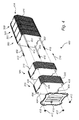
- Fig. 2 shows an energy storage enclosure 202 according to an exemplary embodiment of the invention.
- the energy storage enclosure 202 is made from a foam material which has resilient properties. By the provision of a resilient material, the energy storage enclosure 202 is deformable but also that the energy storage enclosure limits the deformation by attempting to spring back opposite an applied force.
- the energy storage enclosure comprises three wall members 204, 206, 208 which together form a U-shape. Furthermore, the U-shaped energy storage enclosure 202 has an extension in a direction corresponding to a longitudinal direction 210.
- the depicted energy storage enclosure 202 is made in one piece for example via a molding process.
- Fig. 3 shows an energy storage module 300 comprising the energy storage enclosure 202 described with reference to Fig. 2 .
- the U-shaped energy storage enclosure 202 is configured to accommodate a storage unit 302 comprising a plurality of energy storage cells 304 (only one is numbered in order to avoid cluttering in the drawing) arranged adjacent to and stacked with corresponding cooling plates 306 (only one is numbered in order to avoid cluttering in the drawing).
- the energy storage cells 304 and the cooling plates 306 are stacked in the longitudinal direction 210 of the energy storage enclosure 202.
- conduits 320 for providing a coolant such as a liquid to the cooling plates 306.
- the conduits 320 are arranged in grooves 308 formed in the energy storage enclosure 202.
- the energy storage enclosure 202 and the storage unit 302 may be compressed by compressing means configured to apply a force in the longitudinal direction 210.
- the resilient energy storage enclosure 202 is compressed by the force such that the contact pressure between the cooling plate 306 and the energy storage cell 304 increases, but the resilient property of the energy storage enclosure 202 also limits the contact pressure.
- each energy storage module 300 (thus, the energy storage enclosure) may be compressed for example 1-4 mm.
- sides plates 310 are arranged to seal the energy storage enclosure 202 in the longitudinal direction 210.
- the side plates 310 advantageously enable a modular structure, as is more clearly seen in Fig. 4 . For example, a simple replacement of a single energy storage module 300 in a stack of energy storage modules 300 is made possible.
- the side plates 310 may be attached to the energy storage enclosure 202 at end portions 312 of the energy storage enclosure 202 using e.g. glue, ultrasonic welding, staples, vibration welding, etc. A typical thickness of the side plates 310 is between 1 and 4 mm.
- the side plates 310 may be made from e.g. Acrylonitrile butadiene styrene (ABS).
- ABS Acrylonitrile butadiene styrene
- a lid 316 for closing the energy storage enclosure. As shown in Fig. 3 , the lid 316, is part of the energy storage module 300. In some exemplary embodiments, the lid 316 comprises connections for electrically connecting to the battery cells 304.
- flanges 318 are arranged on an outer surface of the energy storage enclosure 202.
- the thermal contact between the energy storage enclosure 202 and an external housing is limited by the flanges 318, thus providing improved thermal isolation for the energy storage cells 304 and the cooling plates 306.
- Fig. 4 shows an exemplary embodiment of the invention.
- several energy storage modules 300 shown in Fig. 3 are arranged along the longitudinal direction 210 forming a battery pack 400.
- compressing elements 402 are arranged to extend from a first end 404 to a second end 406 of each energy storage module 300 and thus also of each of the storage units arranged in the energy storage enclosures 202.
- four pin-bolts 402 are arranged as compressing elements 402 each extending through a through-hole 408 of each of the energy storage enclosures 202 and the side plates 310.
- the pin-bolts 402 each have at least one threaded end 410 such that a nut 412 may screw onto the pin-bolt 402.
- the pin-bolts 402 may further have a stop element on one the end 414 opposite the threaded end 410.
- the stop element prevents the pin-bolt 402 from falling out from the through-hole 408.
- the stop element secures the pin-bolt such that the nut 412 may compress the storage unit 302 and the energy storage enclosure 202 when the nut 412 is tightened to the threaded end 410 of the pin-bolt 402.
- the stop element may for example be a nut.
- end plates 416 are arranged at each side of the stack of energy storage modules 300.
- the end plates 416 are arranged to apply a force on the energy storage enclosures 202 as a result of tightening the nuts 412 on the pin bolts 402.
- the end plates 416 here are depicted as solid plates, they may have through-holes or also be configured as bars or similar as long as they are able to apply the force.
- a plate-like end plate 416 is advantageous because the applied force may be more evenly distributed on the energy storage enclosures 202.
- the amount of compression on the energy storage modules 300 may be controlled by for example monitoring the torque applied on the nut 412 or via ultrasonic measurements on the pin-bolt 410 end.
- the number of energy storage modules 300 may be adapted such that a desired total power output of the battery pack 400 is reached. For example, if the power from one energy storage module is 1.2 kWh (typical power is 1.0-1.5 kWh) eight modules 300 results in a total power of approximately 10 kWh (normal for a hybrid vehicle), or twenty-four modules 300 results in a total power of approximately 30 kWh (normal for an electric vehicle).
- the length of the pin-bolts 410 is adapted to an appropriate length depending on the number of energy storage modules 300 in the battery pack 400. Note also that the size of each energy storage module may be the same.
- the lid 316 is part of the energy storage module 300 meaning that only one size of the lid 316 is needed for a complete battery pack 400.
- the energy storage enclosure may be made from a foam material such as for example expanded polypropylene (EPP).
- EPP expanded polypropylene
- the means for compressing the energy storage enclosure may be realized in ways other than what is shown in the drawings.
- the means for compressing may comprise straps reaching across the energy storage enclosure in the longitudinal direction.
- the straps may be e.g. steel, nylon, fabric, or leather straps.
- Other means may be e.g. strings, ropes, or lashing straps.
Abstract
Description
- The present invention relates to an energy storage enclosure for accommodating an energy storage unit. Furthermore, the present invention relates to an energy storage module and a battery pack comprising the energy storage enclosure.
- Electric and hybrid vehicles have recently become a more common sight on roads worldwide. They have one thing in common and that is they all require a large and powerful rechargeable energy storage, also known as a battery. In most such batteries, several battery cells are stacked together to form a battery powerful enough to provide energy for the vehicle to drive for example several tens of kilometers. The battery cells are in most cases mechanically fixed together with a common frame or enclosure to form a single unit which is conveniently mounted in the vehicle. Furthermore, the size of a battery providing sufficient power for driving an electric or hybrid energy is relatively large, whereby the battery cells tend to be closely packed in order to reduce the size of the battery.
- However, the highly powerful batteries also produce high amounts of heat when in operation. Therefore, an appropriate cooling system is required for transporting heat away from the battery cells in order to prevent that the battery cells or other parts of the battery are damaged from overheating. The heat may for example be transported away from the battery cells by a liquid coolant passed through a cooling system in thermal contact with the battery cells. Alternatively or complimentary, cooling may be achieved by an air cooling system.
- One example of a battery module having a cooling system is disclosed by
US2013/0288098 . The battery module has battery cells stacked in parallel enclosed in a housing. The stack of battery cells is arranged on a cooling plate, and compressible pads are arranged between the stack of battery cells and the cooling plate. In order to maximize the thermal contact between the battery cells, the pads, and the cooling plates, the battery module may be compressed in the vertical direction perpendicular to the stacking direction of the cells. Thereby, the compressible pads are compressed between the battery cells and the cooling plate. - However, the contact surface between the battery cells and the cooling plate is rather limited since the cooling plates are arranged vertically with respect to the stacking direction of the battery cells, as disclosed by
US2013/0288098 , thereby also the thermal contact is relatively weak. Furthermore, the compression pads (and compression limiting pads) make the battery module relatively complicated. - In view of the above, it is a general object of the present invention to provide an energy storage enclosure which provides an improved cooling performance for an energy storage device.
- According to a first aspect it is therefore provided an energy storage enclosure for accommodating a storage unit comprising an energy storage cell arranged adjacent to and stacked with a cooling plate in a longitudinal direction, the cooling plate being in thermal contact with the energy storage cell, wherein the energy storage enclosure comprises: three wall members configured to be in contact with the storage unit, the wall members forming a U-shape and each wall member having an extension in the longitudinal direction, means for compressing the energy storage enclosure arranged to apply a force on the energy storage enclosure and the storage unit in the longitudinal direction, wherein the energy storage enclosure is resilient in the longitudinal direction, such that when a force is applied in the longitudinal direction on the energy storage enclosure and the storage unit, the energy storage enclosure is compressed, and a contact pressure between the cooling plate and the energy storage cell is limited by the resilient energy storage enclosure.
- The present invention is based on the realization that an improved thermal contact between the battery cells and the cooling plates enables a more efficient heat transfer from the battery cells. Furthermore, it is realized that the thermal contact may be improved by applying a force compressing a stack of battery cells and cooling plates. In order to obtain such compression in a reproducible manner, the enclosure is made in a resilient material such that the enclosure may be compressed when exposed to a force and later decompressed when the force is relieved. Hence, the resilient energy storage enclosure allows the energy storage enclosure to be compressed in the longitudinal direction when exposed to a force in the longitudinal direction, and as a result a contact pressure between the cooling plate and the energy storage cell is increased. Additionally, when exposed to the force in the longitudinal direction, the resilient energy storage enclosure limits the compression of the energy storage enclosure by attempting to spring back into the original shape of the energy storage enclosure. Thereby, the resilient energy storage enclosure prevents excessive force on the storage unit which may damage the battery cells. Moreover, the energy storage enclosure is deformable in a non-destructive manner. Thereby, it was realized that the contact pressure between the cooling plates and the energy storage cells may be controlled by controlling the compressing force.
- An energy storage cell may be a battery cell such as for example a lithium-ion pouch cell. Moreover, a cooling plate may be provided with air cooling or liquid cooling means, via for example channels or conduits running through the material of the cooling plate. The energy storage enclosure may accommodate one or more storage units, or one or more energy storage cells. Furthermore, a cooling plate and an energy storage cell are stacked meaning that they are aligned in a longitudinal direction.
- The energy storage enclosure is U-shaped meaning that the three wall members are arranged such that two of the wall members are parallel with each other and the third wall member connects the two parallel wall members. The third wall member is essentially perpendicular to the two parallel wall members. The U-shaped energy storage enclosure may further have an open side opposite the third wall member. Through the open side, opposite the third wall member, cables for electrically connecting to the energy storage cells may be fed. Alternatively, the cables may be fed through holes going through one of the wall members. The holes may be made to have a size suitable to fit the width of the cables.
- The wall members are configured to be in contact with the storage unit meaning that the wall members may be in physical contact with the wall members such that the storage unit is kept in place by the wall members. Furthermore, there may be a thermal contact between the storage unit and the wall members of the energy storage enclosure. In some examples, the energy storage enclosure comprising the three wall members may be arranged to tightly surround the storage unit.
- The longitudinal direction is along an axis substantially parallel with planes of the wall members. For example, the longitudinal direction is along an axis substantially parallel with at least one axis in each of the planes of the wall members.
- The U-shaped energy storage enclosure may have open ends in the longitudinal direction such that in the longitudinal direction a see-through space is formed where the energy storage cells may be stacked. In this way, assembly of storage units in the energy storage enclosure is facilitated.
- According to an embodiment of the invention, the means for compressing may comprise a compressing element arranged to extend from a first end of the storage unit to a second end of the storage unit in the longitudinal direction. A compressing element should be configured such that a compression of the energy storage enclosure and the storage unit is possible with the compressing element. The compressing element may be arranged to extend along the entire length of the storage unit in the longitudinal direction.
- According to an embodiment of the invention, the compressing element may be a pin bolt arranged through a through-hole of the energy storage enclosure. A pin-bolt may be an elongated rod having threads at least on one side of the elongated shape. The pin-bolt extends through the stack of energy storage cells and cooling plates forming a storage unit. If several energy storage enclosures and thereby also several storage units are stacked, the pin-bolt may extend through the entire stack in the longitudinal direction. On one side of the pin-bolt along the longitudinal direction (thus along the elongated shape) there may be a stop element larger than the size of the through-hole rigidly attached to the pin-bolt such that the pin-bolt is may not fall through the through-hole in a direction opposite the stop element. On the side of the pin-bolt opposite the stop element there may be threads on the pin-bolt. A nut may screw onto the pin-bolt on the threads for securing the pin-bolt. By tightening the nut, the energy storage enclosure and the storage unit is compressed such that a contact pressure between the cooling plate and the energy storage cell is increased, although limited by the resilient energy storage enclosure.
- According to an embodiment of the invention, the means for compressing may comprise end plates arranged on each side of the energy storage module in the longitudinal direction to apply the force on the wall members. The means for compressing may also comprise a bar, a rod, or a cross-like element arranged to apply the force.
- According to an embodiment of the invention, the energy storage enclosure is made from a foam material. With a foam material a sufficient thermal insulation qualities and resilient properties may be obtained for the energy storage enclosure. The energy storage enclosure advantageously provides thermal isolation for the battery cell.
- In one embodiment, the foam material is expanded polypropylene (EPP). However, other materials having similar resilient properties and thermal insulation qualities are possible.
- According to an embodiment of the invention, the energy storage enclosure may further comprise flanges arranged on an outer surface of at least one of the wall members. The flanges may improve the ability for an external housing to maintain the position of the energy storage enclosure in the external housing by compressing the flanges. Moreover, the thermal contact is limited between the external housing and the energy storage enclosure by the flanges. The flanges may be ridges and valleys formed on the outside surface of the energy storage enclosure.
- According to an embodiment of the invention, the energy storage enclosure may be formed in one piece. Thereby, manufacturing of the energy storage enclosure may be facilitated since mounting of several parts for assembling the energy storage enclosure is not necessary. Furthermore, the overall assembly of the energy storage enclosure and the storage unit may be performed fast in a convenient manner with maintained cooling performance of an energy storage cell mounted in the energy storage enclosure. The energy storage enclosure may be manufactured using e.g. casting, water cutting, or laser cutting, etc. Furthermore, the flanges may be made as part of the energy storage enclosures when formed in one piece.
- According to an embodiment of the invention, the energy storage enclosure may further comprise a groove formed in an inner side of a wall member of the energy storage enclosure for receiving a transfer conduit for transferring a coolant to the cooling plate. For example, a groove may be formed during manufacturing of the energy storage enclosure. The groove may be shaped to house a conduit, for example a pipe conduit, such that the energy storage cell may be placed adjacent to the pipe. The groove may be arranged along the longitudinal direction such that the coolant may be transferred to more than one cooling plate arranged along the longitudinal direction. Furthermore, the conduit/pipe may not be rigidly attached to the groove but is instead allowed to slide in the groove. In this way, the energy storage enclosure may be compressed without compressing the conduit which otherwise may cause damage to the conduit.
- According to a second aspect of the present invention, there is provided an energy storage module comprising: an energy storage enclosure according to the previous aspect and/or embodiments mentioned above; and a storage unit comprising an energy storage cell arranged adjacent to and stacked with a cooling plate in a longitudinal direction, the cooling plate being in thermal contact with the energy storage cell, wherein the storage unit is arranged in the energy storage enclosure. Thus, the energy storage enclosure may accommodate an energy storage cell and a cooling plate. Thereby, the energy storage enclosure together with the energy storage cell and the cooling plate are provided in a single unit.
- According to an embodiment of the invention, side plates may be arranged to seal the energy storage enclosure in the longitudinal direction. The end plates are substantially rigid and preferably made from a plastic material such as e.g. Acrylonitrile butadiene styrene (ABS). The side plates may be attached to the energy storage enclosures at end portions using e.g. glue, ultrasonic welding, staples, vibration welding, etc. The side plates improve the stability of the energy storage enclosure. Furthermore, the side plates enable a modular configuration of an energy storage enclosure with the storage unit. A typical thickness of the side plate is between 1 and 4 mm.
- According to an embodiment of the invention, the energy storage enclosure may accommodate at least two energy storage cells and at least one cooling plate stacked and in thermal contact with the energy storage cells.
- Further effects and features of this second aspect of the present invention are largely analogous to those described above in connection with the first aspect of the invention.
- According to a third aspect of the present invention, there is provided a battery pack comprising a plurality of energy storage modules.
- The modular configuration of the battery pack enables a facilitated way of for example replacing an energy storage module or performing maintenance of a single module since an energy storage module is easily removed from the e.g. a battery pack with several energy storage modules. Furthermore, depending on the desired power output of the battery pack, the number of energy storage modules may be adapted thereafter.
- According to an embodiment of the invention, the energy storage modules may be stacked in the longitudinal direction, wherein the means for compressing are arranged to apply the force on the battery pack in the longitudinal direction causing a compression of each energy storage enclosure of the battery pack.
- According to an embodiment of the invention, the battery pack may further comprise a housing arranged to accommodate the energy storage modules of the battery pack. In other words, a housing, which may be a rigid housing, encloses the energy storage modules. Furthermore, flanges (if present) of the energy storage enclosures of the energy storage modules may be deformed by the housing which ensures a thorough mounting of the energy storage modules in the housing. Furthermore, if the flanges are present on the energy storage enclosure, a reduced thermal contact between the housing and the battery cells is obtained.
- Further effects and features of this third aspect of the present invention are largely analogous to those described above in connection with the first and the second aspects of the invention.
- Further features of, and advantages with, the present invention will become apparent when studying the appended claims and the following description. The skilled person realizes that different features of the present invention may be combined to create embodiments other than those described in the following, without departing from the scope of the present invention.
- These and other aspects of the present invention will now be described in more detail, with reference to the appended drawings showing a currently preferred embodiment of the invention, wherein:
-
Fig. 1 schematically shows an exemplary application for an exemplary embodiment of an energy storage enclosure; -
Fig. 2 shows an exemplary energy storage enclosure according to an embodiment of the present invention; -
Fig. 3 shows an exemplary energy storage module according to an embodiment of the present invention; and -
Fig. 4 shows an exemplary embodiment of the present invention; - In the following description, the present invention is mainly described with reference to an energy storage enclosure for an energy storage arranged in an electric vehicle in the form of a car. However, the invention may be applied to any type of electric vehicle such as a truck, a fork lift, a boat, etc.
-
Fig. 1 illustrates anelectric vehicle 100 comprising anenergy storage 102. Theenergy storage 102 is configured to provide power for operating theelectric vehicle 100. Theelectric vehicle 100 is depicted as an electric car, however any other vehicle, such as e.g. a truck is suitable. Theenergy storage 102 of this electric vehicle comprises an energy storage enclosure according to an exemplary embodiment of the present invention. -
Fig. 2 shows anenergy storage enclosure 202 according to an exemplary embodiment of the invention. Theenergy storage enclosure 202 is made from a foam material which has resilient properties. By the provision of a resilient material, theenergy storage enclosure 202 is deformable but also that the energy storage enclosure limits the deformation by attempting to spring back opposite an applied force. The energy storage enclosure comprises threewall members energy storage enclosure 202 has an extension in a direction corresponding to alongitudinal direction 210. InFig. 2 , the depictedenergy storage enclosure 202 is made in one piece for example via a molding process. -
Fig. 3 shows anenergy storage module 300 comprising theenergy storage enclosure 202 described with reference toFig. 2 . The U-shapedenergy storage enclosure 202 is configured to accommodate astorage unit 302 comprising a plurality of energy storage cells 304 (only one is numbered in order to avoid cluttering in the drawing) arranged adjacent to and stacked with corresponding cooling plates 306 (only one is numbered in order to avoid cluttering in the drawing). Thereby, theenergy storage cells 304 and the coolingplates 306 are stacked in thelongitudinal direction 210 of theenergy storage enclosure 202. Furthermore, there may beconduits 320 for providing a coolant such as a liquid to the coolingplates 306. Theconduits 320 are arranged ingrooves 308 formed in theenergy storage enclosure 202. Thereby, heat generated by theenergy storage cell 304 may be transported away from theenergy storage cell 304 by the coolant. In order to obtain sufficient cooling performance by thecooling plate 306, a sufficient thermal contact between the coolingplate 306 and theenergy storage cell 304 is required. The thermal contact is influenced by the contact pressure between the coolingplate 306 and theenergy storage cell 304. Therefore, theenergy storage enclosure 202 and thestorage unit 302 may be compressed by compressing means configured to apply a force in thelongitudinal direction 210. The resilientenergy storage enclosure 202 is compressed by the force such that the contact pressure between the coolingplate 306 and theenergy storage cell 304 increases, but the resilient property of theenergy storage enclosure 202 also limits the contact pressure. Thereby, improved cooling of theenergy storage cell 304 may be obtained by compressing theenergy storage enclosure 202 and thestorage unit 302 in thelongitudinal direction 210 such that the thermal contact between the coolingplate 306 and theenergy storage cell 304 is improved. When compressed, each energy storage module 300 (thus, the energy storage enclosure) may be compressed for example 1-4 mm. Furthermore, sidesplates 310 are arranged to seal theenergy storage enclosure 202 in thelongitudinal direction 210. Theside plates 310 advantageously enable a modular structure, as is more clearly seen inFig. 4 . For example, a simple replacement of a singleenergy storage module 300 in a stack ofenergy storage modules 300 is made possible. Theside plates 310 may be attached to theenergy storage enclosure 202 atend portions 312 of theenergy storage enclosure 202 using e.g. glue, ultrasonic welding, staples, vibration welding, etc. A typical thickness of theside plates 310 is between 1 and 4 mm. Theside plates 310 may be made from e.g. Acrylonitrile butadiene styrene (ABS). Also shown inFig. 3 is alid 316 for closing the energy storage enclosure. As shown inFig. 3 , thelid 316, is part of theenergy storage module 300. In some exemplary embodiments, thelid 316 comprises connections for electrically connecting to thebattery cells 304. - Furthermore, in the embodiment shown in
Fig. 3 ,flanges 318 are arranged on an outer surface of theenergy storage enclosure 202. The thermal contact between theenergy storage enclosure 202 and an external housing is limited by theflanges 318, thus providing improved thermal isolation for theenergy storage cells 304 and the coolingplates 306. -
Fig. 4 shows an exemplary embodiment of the invention. InFig. 4 , severalenergy storage modules 300 shown inFig. 3 are arranged along thelongitudinal direction 210 forming abattery pack 400. As shown inFig. 4 , compressingelements 402 are arranged to extend from afirst end 404 to asecond end 406 of eachenergy storage module 300 and thus also of each of the storage units arranged in theenergy storage enclosures 202. In this exemplary embodiment, four pin-bolts 402 are arranged as compressingelements 402 each extending through a through-hole 408 of each of theenergy storage enclosures 202 and theside plates 310. In addition, the pin-bolts 402 each have at least one threadedend 410 such that anut 412 may screw onto the pin-bolt 402. The pin-bolts 402 may further have a stop element on one theend 414 opposite the threadedend 410. The stop element prevents the pin-bolt 402 from falling out from the through-hole 408. Furthermore, the stop element secures the pin-bolt such that thenut 412 may compress thestorage unit 302 and theenergy storage enclosure 202 when thenut 412 is tightened to the threadedend 410 of the pin-bolt 402. The stop element may for example be a nut. Furthermore,end plates 416 are arranged at each side of the stack ofenergy storage modules 300. Theend plates 416 are arranged to apply a force on theenergy storage enclosures 202 as a result of tightening thenuts 412 on thepin bolts 402. Note that, although theend plates 416 here are depicted as solid plates, they may have through-holes or also be configured as bars or similar as long as they are able to apply the force. A plate-like end plate 416 is advantageous because the applied force may be more evenly distributed on theenergy storage enclosures 202. The amount of compression on theenergy storage modules 300 may be controlled by for example monitoring the torque applied on thenut 412 or via ultrasonic measurements on the pin-bolt 410 end. - With the
battery pack 400, the number ofenergy storage modules 300 may be adapted such that a desired total power output of thebattery pack 400 is reached. For example, if the power from one energy storage module is 1.2 kWh (typical power is 1.0-1.5 kWh) eightmodules 300 results in a total power of approximately 10 kWh (normal for a hybrid vehicle), or twenty-fourmodules 300 results in a total power of approximately 30 kWh (normal for an electric vehicle). Naturally, the length of the pin-bolts 410 is adapted to an appropriate length depending on the number ofenergy storage modules 300 in thebattery pack 400. Note also that the size of each energy storage module may be the same. - Moreover, the
lid 316 is part of theenergy storage module 300 meaning that only one size of thelid 316 is needed for acomplete battery pack 400. - In each of the above described exemplary embodiments in
Figs 2-4 , the energy storage enclosure may be made from a foam material such as for example expanded polypropylene (EPP). - Additionally, variations to the disclosed embodiments can be understood and effected by the skilled person in practicing the claimed invention, from a study of the drawings, the disclosure, and the appended claims. For example, the means for compressing the energy storage enclosure may be realized in ways other than what is shown in the drawings. For example, the means for compressing may comprise straps reaching across the energy storage enclosure in the longitudinal direction. The straps may be e.g. steel, nylon, fabric, or leather straps. Other means may be e.g. strings, ropes, or lashing straps.
- In the claims, the word "comprising" does not exclude other elements or steps, and the indefinite article "a" or "an" does not exclude a plurality. The mere fact that certain measures are recited in mutually different dependent claims does not indicate that a combination of these measured cannot be used to advantage.
Claims (15)
- An energy storage enclosure (202) for accommodating a storage unit (302) comprising an energy storage cell (304) arranged adjacent to and stacked with a cooling plate (306) in a longitudinal direction (210), said cooling plate (306) being in thermal contact with said energy storage cell (304), wherein said energy storage enclosure (202) comprises:three wall members (204, 206, 208) configured to be in contact with said storage unit (302), said wall members (204, 206, 208) forming a U-shape and each wall member (204, 206, 208) having an extension in said longitudinal direction (210),means (402, 416) for compressing said energy storage enclosure (202) arranged to apply a force on said energy storage enclosure (202) and said storage unit (302) in said longitudinal direction (210),wherein said energy storage enclosure (202) is resilient in the longitudinal direction (210), such that when a force is applied in said longitudinal direction (210) on said energy storage enclosure (202) and said storage unit (302), said energy storage enclosure (202) is compressed, and a contact pressure between said cooling plate (306) and said energy storage cell (304) is limited by said resilient energy storage enclosure (202).
- The energy storage enclosure (202) according to claim 1,
wherein said means (402, 416) for compressing comprises a compressing element (402) arranged to extend from a first end of said storage unit (302) to a second end of said storage unit (302) in said longitudinal direction (210). - The energy storage enclosure (202) according to claim 2,
wherein said compressing element (402) is a pin bolt arranged through a through-hole (408) of said energy storage enclosure (202). - The energy storage enclosure (202) according to any of the preceding claims, wherein said means (402, 416) for compressing comprises end plates (416) arranged on each side of said energy storage enclosure (202) in said longitudinal direction (210) to apply said force on said wall members (204, 206, 208).
- The energy storage enclosure (202) according to any one of the preceding claims, wherein said energy storage enclosure (202) is made from a foam material.
- The energy storage enclosure (202) according to claim 5,
wherein said foam material is expanded polypropylene (EPP). - The energy storage enclosure (202) according to any one of the preceding claims, further comprising flanges (318) arranged on an outer surface of at least one of said wall members (204, 206, 208).
- The energy storage enclosure (202) according to any one of the preceding claims, wherein said energy storage enclosure (202) is formed in one piece.
- The energy storage enclosure (202) according to any one of the preceding claims, further comprising a groove (308) formed in an inner side of a wall member (204, 206, 208) of said energy storage enclosure (202) for receiving a transfer conduit (320) for transferring a coolant to said cooling plate (306).
- Energy storage module (300) comprising:an energy storage enclosure (202) according to any one of the preceding claims; anda storage unit (302) comprising an energy storage cell (304) arranged adjacent to and stacked with a cooling plate (306) in a longitudinal direction (210), said cooling plate (306) being in thermal contact with said energy storage cell (304),wherein said storage unit (302) is arranged in said energy storage enclosure (202).
- The energy storage module according to claim 10, comprising side plates arranged to seal said energy storage enclosure (202) in said longitudinal direction (210), said side plates being in contact with said wall members (204, 206, 208).
- The energy storage module (300) according to any of claims 10 or 11, wherein said energy storage enclosure (202) accommodates at least two energy storage cells (304) and at least one cooling plate (306) stacked and in thermal contact with said energy storage cells (304).
- A battery pack comprising a plurality of energy storage modules (300) according to any one of claims 10 to 12.
- A battery pack (400) according to claim 13, wherein said energy storage modules (300) are stacked in said longitudinal direction (210), wherein said means (402, 416) for compressing are arranged to apply said force on said battery pack in said longitudinal direction (210) causing a compression of each energy storage enclosure (202) of said battery pack.
- The battery pack (400) according to claim 14, further comprising a housing arranged to accommodate said energy storage modules (300).
Priority Applications (3)
| Application Number | Priority Date | Filing Date | Title |
|---|---|---|---|
| EP14157915.1A EP2916366B1 (en) | 2014-03-05 | 2014-03-05 | Energy storage enclosure |
| CN201510086955.8A CN104900822B (en) | 2014-03-05 | 2015-02-25 | Energy storage enclosure |
| US14/632,110 US10170809B2 (en) | 2014-03-05 | 2015-02-26 | Energy storage enclosure |
Applications Claiming Priority (1)
| Application Number | Priority Date | Filing Date | Title |
|---|---|---|---|
| EP14157915.1A EP2916366B1 (en) | 2014-03-05 | 2014-03-05 | Energy storage enclosure |
Publications (2)
| Publication Number | Publication Date |
|---|---|
| EP2916366A1 true EP2916366A1 (en) | 2015-09-09 |
| EP2916366B1 EP2916366B1 (en) | 2018-01-31 |
Family
ID=50190366
Family Applications (1)
| Application Number | Title | Priority Date | Filing Date |
|---|---|---|---|
| EP14157915.1A Active EP2916366B1 (en) | 2014-03-05 | 2014-03-05 | Energy storage enclosure |
Country Status (3)
| Country | Link |
|---|---|
| US (1) | US10170809B2 (en) |
| EP (1) | EP2916366B1 (en) |
| CN (1) | CN104900822B (en) |
Cited By (1)
| Publication number | Priority date | Publication date | Assignee | Title |
|---|---|---|---|---|
| EP3188283A1 (en) * | 2015-12-29 | 2017-07-05 | SK Innovation Co., Ltd. | Battery module and method of manufacturing the same |
Families Citing this family (17)
| Publication number | Priority date | Publication date | Assignee | Title |
|---|---|---|---|---|
| DE102012218162B4 (en) * | 2012-10-04 | 2023-12-14 | Bayerische Motorenwerke Aktiengesellschaft | Energy storage arrangement |
| CN105762314B (en) * | 2016-04-15 | 2019-01-08 | 宁德时代新能源科技股份有限公司 | Battery cell buffer structure and battery pack adopting same |
| KR102101906B1 (en) * | 2016-10-21 | 2020-04-17 | 주식회사 엘지화학 | Battery Pack Comprising Coupling Member Having Assembling Guide Function |
| DE102017204412A1 (en) | 2017-03-16 | 2018-09-20 | Audi Ag | Battery for a motor vehicle and motor vehicle |
| KR102110543B1 (en) * | 2017-03-22 | 2020-05-13 | 주식회사 엘지화학 | Battery pack |
| US10971777B2 (en) * | 2017-04-11 | 2021-04-06 | Ford Global Technologies, Llc | Traction battery support assembly and method |
| GB2568242A (en) * | 2017-11-06 | 2019-05-15 | Moog Unna Gmbh | Secure Battery Housing Tray |
| DE102018202263A1 (en) * | 2018-02-14 | 2019-08-14 | Conti Temic Microelectronic Gmbh | Battery for a motor vehicle |
| FR3079672B1 (en) * | 2018-03-27 | 2020-03-06 | Valeo Systemes Thermiques | MOTOR VEHICLE BATTERY CELL COOLING SYSTEM |
| TWI678016B (en) * | 2018-11-22 | 2019-11-21 | 國家中山科學研究院 | Battery module and liquid cooling device |
| DE102019204652A1 (en) * | 2019-04-02 | 2020-10-08 | Mahle International Gmbh | accumulator |
| US11267354B2 (en) * | 2019-08-16 | 2022-03-08 | DESIGNWERK TECHNOLOGIES GmbH | Power supply |
| DE102019127588B3 (en) * | 2019-10-14 | 2020-12-10 | Dr. Ing. H.C. F. Porsche Aktiengesellschaft | Energy storage arrangement for a motor vehicle and motor vehicle comprising such an energy storage arrangement |
| DE102020105626A1 (en) | 2020-03-03 | 2021-09-09 | Woco Industrietechnik Gmbh | Energy storage for electrical energy |
| US11909020B2 (en) | 2020-05-28 | 2024-02-20 | Cummins Inc. | Battery packs with reduced weight and improved thermal performance |
| US11799150B2 (en) | 2020-07-17 | 2023-10-24 | Toyota Motor Engineering & Manufacturing North America, Inc. | Cooling structure for hybrid-electric vehicle battery cell assemblies |
| DE102022100410A1 (en) * | 2022-01-10 | 2023-07-13 | Webasto SE | Battery case for a vehicle battery and vehicle battery |
Citations (6)
| Publication number | Priority date | Publication date | Assignee | Title |
|---|---|---|---|---|
| GB1386025A (en) * | 1971-11-25 | 1975-03-05 | Varta Ag | Self-supporting case for accumulators or storage batteries |
| US20110212355A1 (en) * | 2010-02-26 | 2011-09-01 | Gm Global Technology Operations, Inc. | U-formed cooling plate with solid fins for lithium pouch cells |
| DE102010047453A1 (en) * | 2010-10-04 | 2012-04-05 | Li-Tec Battery Gmbh | Housing for receiving a flat electrochemical cell |
| US20120183823A1 (en) * | 2009-04-24 | 2012-07-19 | Von Borck Felix | Battery module |
| US20130266838A1 (en) * | 2010-09-02 | 2013-10-10 | Akasol Engineering Gmbh | Cooling module and method for producing a cooling module |
| US20130288098A1 (en) | 2012-04-30 | 2013-10-31 | Cobasys, Llc | Enhanced thermal contact |
Family Cites Families (5)
| Publication number | Priority date | Publication date | Assignee | Title |
|---|---|---|---|---|
| KR100648697B1 (en) * | 2005-03-11 | 2006-11-23 | 삼성에스디아이 주식회사 | Secondary battery module |
| US8835039B2 (en) * | 2011-10-21 | 2014-09-16 | Avl Powertrain Engineering, Inc. | Battery cooling plate and cooling system |
| WO2013095476A1 (en) * | 2011-12-21 | 2013-06-27 | Mission Motors | Battery module |
| US8968912B2 (en) * | 2011-12-21 | 2015-03-03 | Ford Global Technologies, Llc | Method and apparatus for manufacturing a battery for a vehicle |
| DE102012108762A1 (en) * | 2012-09-18 | 2014-03-20 | Dr. Ing. H.C. F. Porsche Aktiengesellschaft | battery means |
-
2014
- 2014-03-05 EP EP14157915.1A patent/EP2916366B1/en active Active
-
2015
- 2015-02-25 CN CN201510086955.8A patent/CN104900822B/en active Active
- 2015-02-26 US US14/632,110 patent/US10170809B2/en active Active
Patent Citations (6)
| Publication number | Priority date | Publication date | Assignee | Title |
|---|---|---|---|---|
| GB1386025A (en) * | 1971-11-25 | 1975-03-05 | Varta Ag | Self-supporting case for accumulators or storage batteries |
| US20120183823A1 (en) * | 2009-04-24 | 2012-07-19 | Von Borck Felix | Battery module |
| US20110212355A1 (en) * | 2010-02-26 | 2011-09-01 | Gm Global Technology Operations, Inc. | U-formed cooling plate with solid fins for lithium pouch cells |
| US20130266838A1 (en) * | 2010-09-02 | 2013-10-10 | Akasol Engineering Gmbh | Cooling module and method for producing a cooling module |
| DE102010047453A1 (en) * | 2010-10-04 | 2012-04-05 | Li-Tec Battery Gmbh | Housing for receiving a flat electrochemical cell |
| US20130288098A1 (en) | 2012-04-30 | 2013-10-31 | Cobasys, Llc | Enhanced thermal contact |
Cited By (4)
| Publication number | Priority date | Publication date | Assignee | Title |
|---|---|---|---|---|
| EP3188283A1 (en) * | 2015-12-29 | 2017-07-05 | SK Innovation Co., Ltd. | Battery module and method of manufacturing the same |
| KR20170078013A (en) * | 2015-12-29 | 2017-07-07 | 에스케이이노베이션 주식회사 | Battery module and manufacturing method thereof |
| US10930985B2 (en) | 2015-12-29 | 2021-02-23 | Sk Innovation Co., Ltd. | Battery module and method of manufacturing the same |
| US11652246B2 (en) | 2015-12-29 | 2023-05-16 | Sk On Co., Ltd. | Battery module and method of manufacturing the same |
Also Published As
| Publication number | Publication date |
|---|---|
| CN104900822B (en) | 2020-01-17 |
| US10170809B2 (en) | 2019-01-01 |
| CN104900822A (en) | 2015-09-09 |
| US20150255837A1 (en) | 2015-09-10 |
| EP2916366B1 (en) | 2018-01-31 |
Similar Documents
| Publication | Publication Date | Title |
|---|---|---|
| EP2916366B1 (en) | Energy storage enclosure | |
| US10135103B2 (en) | Cooling circuit with cooling fluid for lithium batteries, and a vehicle comprising said cooling circuit | |
| EP3002802B1 (en) | Energy storage module and system | |
| US6761992B1 (en) | Restraining bands for battery pack | |
| JP4858726B2 (en) | Secondary battery holding structure | |
| CN108431989B (en) | Housing for accommodating a fuel cell stack, a cell stack or a capacitor stack | |
| CN204128420U (en) | Battery heat exchanger | |
| EP2771940B1 (en) | A multi-cell battery assembly | |
| US11251490B2 (en) | Battery module and vehicle equipped with same | |
| KR100669333B1 (en) | Secondary battery module | |
| KR101471242B1 (en) | Battery unit | |
| US20140087231A1 (en) | Energy storage apparatus | |
| US20130164578A1 (en) | Battery module | |
| US20140106199A1 (en) | Energy storage apparatus having a temperature control device | |
| US9023502B2 (en) | System for the storage of electric energy with reduced thickness for a vehicle with electric propulsion | |
| KR101799565B1 (en) | Battery Pack of Improved Safety | |
| JP6990642B2 (en) | Power storage module and manufacturing method of power storage module | |
| US11217840B2 (en) | Battery system with internal cooling passages | |
| KR102317506B1 (en) | Battery pack | |
| KR20150043291A (en) | Dynamic pressure control in a battery assembly | |
| JP5421836B2 (en) | Power supply | |
| WO2012125115A1 (en) | Battery module, vehicle, electric device and method | |
| JP5688152B2 (en) | Method of tightening lithium ion storage battery, lithium ion storage battery, and vehicle equipped with lithium ion storage battery | |
| JP6948564B2 (en) | Battery module | |
| CN111682138A (en) | Battery module, battery package and electric motor car |
Legal Events
| Date | Code | Title | Description |
|---|---|---|---|
| PUAI | Public reference made under article 153(3) epc to a published international application that has entered the european phase |
Free format text: ORIGINAL CODE: 0009012 |
|
| AK | Designated contracting states |
Kind code of ref document: A1 Designated state(s): AL AT BE BG CH CY CZ DE DK EE ES FI FR GB GR HR HU IE IS IT LI LT LU LV MC MK MT NL NO PL PT RO RS SE SI SK SM TR |
|
| AX | Request for extension of the european patent |
Extension state: BA ME |
|
| 17P | Request for examination filed |
Effective date: 20160309 |
|
| RBV | Designated contracting states (corrected) |
Designated state(s): AL AT BE BG CH CY CZ DE DK EE ES FI FR GB GR HR HU IE IS IT LI LT LU LV MC MK MT NL NO PL PT RO RS SE SI SK SM TR |
|
| 17Q | First examination report despatched |
Effective date: 20170522 |
|
| REG | Reference to a national code |
Ref country code: DE Ref legal event code: R079 Ref document number: 602014020233 Country of ref document: DE Free format text: PREVIOUS MAIN CLASS: H01M0002020000 Ipc: H01M0010655700 |
|
| RIC1 | Information provided on ipc code assigned before grant |
Ipc: H01M 10/6557 20140101AFI20170824BHEP Ipc: H01M 10/04 20060101ALI20170824BHEP Ipc: H01M 10/625 20140101ALI20170824BHEP Ipc: H01M 10/613 20140101ALI20170824BHEP Ipc: H01M 10/658 20140101ALI20170824BHEP Ipc: H01M 10/6555 20140101ALI20170824BHEP Ipc: H01M 2/10 20060101ALI20170824BHEP |
|
| GRAP | Despatch of communication of intention to grant a patent |
Free format text: ORIGINAL CODE: EPIDOSNIGR1 |
|
| RIC1 | Information provided on ipc code assigned before grant |
Ipc: H01M 10/6557 20140101AFI20170914BHEP Ipc: H01M 2/10 20060101ALI20170914BHEP Ipc: H01M 10/613 20140101ALI20170914BHEP Ipc: H01M 10/625 20140101ALI20170914BHEP Ipc: H01M 10/658 20140101ALI20170914BHEP Ipc: H01M 10/04 20060101ALI20170914BHEP |
|
| INTG | Intention to grant announced |
Effective date: 20171011 |
|
| GRAS | Grant fee paid |
Free format text: ORIGINAL CODE: EPIDOSNIGR3 |
|
| GRAA | (expected) grant |
Free format text: ORIGINAL CODE: 0009210 |
|
| GRAT | Correction requested after decision to grant or after decision to maintain patent in amended form |
Free format text: ORIGINAL CODE: EPIDOSNCDEC |
|
| AK | Designated contracting states |
Kind code of ref document: B1 Designated state(s): AL AT BE BG CH CY CZ DE DK EE ES FI FR GB GR HR HU IE IS IT LI LT LU LV MC MK MT NL NO PL PT RO RS SE SI SK SM TR |
|
| REG | Reference to a national code |
Ref country code: GB Ref legal event code: FG4D Ref country code: CH Ref legal event code: EP |
|
| REG | Reference to a national code |
Ref country code: AT Ref legal event code: REF Ref document number: 968138 Country of ref document: AT Kind code of ref document: T Effective date: 20180215 |
|
| REG | Reference to a national code |
Ref country code: IE Ref legal event code: FG4D |
|
| REG | Reference to a national code |
Ref country code: DE Ref legal event code: R096 Ref document number: 602014020233 Country of ref document: DE |
|
| REG | Reference to a national code |
Ref country code: SE Ref legal event code: TRGR |
|
| REG | Reference to a national code |
Ref country code: NL Ref legal event code: MP Effective date: 20180131 |
|
| REG | Reference to a national code |
Ref country code: LT Ref legal event code: MG4D |
|
| REG | Reference to a national code |
Ref country code: AT Ref legal event code: MK05 Ref document number: 968138 Country of ref document: AT Kind code of ref document: T Effective date: 20180131 |
|
| PG25 | Lapsed in a contracting state [announced via postgrant information from national office to epo] |
Ref country code: FI Free format text: LAPSE BECAUSE OF FAILURE TO SUBMIT A TRANSLATION OF THE DESCRIPTION OR TO PAY THE FEE WITHIN THE PRESCRIBED TIME-LIMIT Effective date: 20180131 Ref country code: LT Free format text: LAPSE BECAUSE OF FAILURE TO SUBMIT A TRANSLATION OF THE DESCRIPTION OR TO PAY THE FEE WITHIN THE PRESCRIBED TIME-LIMIT Effective date: 20180131 Ref country code: HR Free format text: LAPSE BECAUSE OF FAILURE TO SUBMIT A TRANSLATION OF THE DESCRIPTION OR TO PAY THE FEE WITHIN THE PRESCRIBED TIME-LIMIT Effective date: 20180131 Ref country code: NO Free format text: LAPSE BECAUSE OF FAILURE TO SUBMIT A TRANSLATION OF THE DESCRIPTION OR TO PAY THE FEE WITHIN THE PRESCRIBED TIME-LIMIT Effective date: 20180430 Ref country code: ES Free format text: LAPSE BECAUSE OF FAILURE TO SUBMIT A TRANSLATION OF THE DESCRIPTION OR TO PAY THE FEE WITHIN THE PRESCRIBED TIME-LIMIT Effective date: 20180131 Ref country code: NL Free format text: LAPSE BECAUSE OF FAILURE TO SUBMIT A TRANSLATION OF THE DESCRIPTION OR TO PAY THE FEE WITHIN THE PRESCRIBED TIME-LIMIT Effective date: 20180131 |
|
| PG25 | Lapsed in a contracting state [announced via postgrant information from national office to epo] |
Ref country code: GR Free format text: LAPSE BECAUSE OF FAILURE TO SUBMIT A TRANSLATION OF THE DESCRIPTION OR TO PAY THE FEE WITHIN THE PRESCRIBED TIME-LIMIT Effective date: 20180501 Ref country code: PL Free format text: LAPSE BECAUSE OF FAILURE TO SUBMIT A TRANSLATION OF THE DESCRIPTION OR TO PAY THE FEE WITHIN THE PRESCRIBED TIME-LIMIT Effective date: 20180131 Ref country code: RS Free format text: LAPSE BECAUSE OF FAILURE TO SUBMIT A TRANSLATION OF THE DESCRIPTION OR TO PAY THE FEE WITHIN THE PRESCRIBED TIME-LIMIT Effective date: 20180131 Ref country code: LV Free format text: LAPSE BECAUSE OF FAILURE TO SUBMIT A TRANSLATION OF THE DESCRIPTION OR TO PAY THE FEE WITHIN THE PRESCRIBED TIME-LIMIT Effective date: 20180131 Ref country code: IS Free format text: LAPSE BECAUSE OF FAILURE TO SUBMIT A TRANSLATION OF THE DESCRIPTION OR TO PAY THE FEE WITHIN THE PRESCRIBED TIME-LIMIT Effective date: 20180531 Ref country code: BG Free format text: LAPSE BECAUSE OF FAILURE TO SUBMIT A TRANSLATION OF THE DESCRIPTION OR TO PAY THE FEE WITHIN THE PRESCRIBED TIME-LIMIT Effective date: 20180430 Ref country code: AT Free format text: LAPSE BECAUSE OF FAILURE TO SUBMIT A TRANSLATION OF THE DESCRIPTION OR TO PAY THE FEE WITHIN THE PRESCRIBED TIME-LIMIT Effective date: 20180131 |
|
| PG25 | Lapsed in a contracting state [announced via postgrant information from national office to epo] |
Ref country code: AL Free format text: LAPSE BECAUSE OF FAILURE TO SUBMIT A TRANSLATION OF THE DESCRIPTION OR TO PAY THE FEE WITHIN THE PRESCRIBED TIME-LIMIT Effective date: 20180131 Ref country code: EE Free format text: LAPSE BECAUSE OF FAILURE TO SUBMIT A TRANSLATION OF THE DESCRIPTION OR TO PAY THE FEE WITHIN THE PRESCRIBED TIME-LIMIT Effective date: 20180131 Ref country code: RO Free format text: LAPSE BECAUSE OF FAILURE TO SUBMIT A TRANSLATION OF THE DESCRIPTION OR TO PAY THE FEE WITHIN THE PRESCRIBED TIME-LIMIT Effective date: 20180131 Ref country code: IT Free format text: LAPSE BECAUSE OF FAILURE TO SUBMIT A TRANSLATION OF THE DESCRIPTION OR TO PAY THE FEE WITHIN THE PRESCRIBED TIME-LIMIT Effective date: 20180131 |
|
| REG | Reference to a national code |
Ref country code: CH Ref legal event code: PL |
|
| REG | Reference to a national code |
Ref country code: DE Ref legal event code: R097 Ref document number: 602014020233 Country of ref document: DE |
|
| PG25 | Lapsed in a contracting state [announced via postgrant information from national office to epo] |
Ref country code: CZ Free format text: LAPSE BECAUSE OF FAILURE TO SUBMIT A TRANSLATION OF THE DESCRIPTION OR TO PAY THE FEE WITHIN THE PRESCRIBED TIME-LIMIT Effective date: 20180131 Ref country code: SK Free format text: LAPSE BECAUSE OF FAILURE TO SUBMIT A TRANSLATION OF THE DESCRIPTION OR TO PAY THE FEE WITHIN THE PRESCRIBED TIME-LIMIT Effective date: 20180131 Ref country code: MC Free format text: LAPSE BECAUSE OF FAILURE TO SUBMIT A TRANSLATION OF THE DESCRIPTION OR TO PAY THE FEE WITHIN THE PRESCRIBED TIME-LIMIT Effective date: 20180131 Ref country code: DK Free format text: LAPSE BECAUSE OF FAILURE TO SUBMIT A TRANSLATION OF THE DESCRIPTION OR TO PAY THE FEE WITHIN THE PRESCRIBED TIME-LIMIT Effective date: 20180131 Ref country code: SM Free format text: LAPSE BECAUSE OF FAILURE TO SUBMIT A TRANSLATION OF THE DESCRIPTION OR TO PAY THE FEE WITHIN THE PRESCRIBED TIME-LIMIT Effective date: 20180131 |
|
| PLBE | No opposition filed within time limit |
Free format text: ORIGINAL CODE: 0009261 |
|
| STAA | Information on the status of an ep patent application or granted ep patent |
Free format text: STATUS: NO OPPOSITION FILED WITHIN TIME LIMIT |
|
| REG | Reference to a national code |
Ref country code: BE Ref legal event code: MM Effective date: 20180331 |
|
| REG | Reference to a national code |
Ref country code: IE Ref legal event code: MM4A |
|
| PG25 | Lapsed in a contracting state [announced via postgrant information from national office to epo] |
Ref country code: LU Free format text: LAPSE BECAUSE OF NON-PAYMENT OF DUE FEES Effective date: 20180305 |
|
| 26N | No opposition filed |
Effective date: 20181102 |
|
| PG25 | Lapsed in a contracting state [announced via postgrant information from national office to epo] |
Ref country code: IE Free format text: LAPSE BECAUSE OF NON-PAYMENT OF DUE FEES Effective date: 20180305 |
|
| PG25 | Lapsed in a contracting state [announced via postgrant information from national office to epo] |
Ref country code: BE Free format text: LAPSE BECAUSE OF NON-PAYMENT OF DUE FEES Effective date: 20180331 Ref country code: SI Free format text: LAPSE BECAUSE OF FAILURE TO SUBMIT A TRANSLATION OF THE DESCRIPTION OR TO PAY THE FEE WITHIN THE PRESCRIBED TIME-LIMIT Effective date: 20180131 Ref country code: LI Free format text: LAPSE BECAUSE OF NON-PAYMENT OF DUE FEES Effective date: 20180331 Ref country code: CH Free format text: LAPSE BECAUSE OF NON-PAYMENT OF DUE FEES Effective date: 20180331 |
|
| PG25 | Lapsed in a contracting state [announced via postgrant information from national office to epo] |
Ref country code: FR Free format text: LAPSE BECAUSE OF NON-PAYMENT OF DUE FEES Effective date: 20180331 |
|
| PGFP | Annual fee paid to national office [announced via postgrant information from national office to epo] |
Ref country code: IT Payment date: 20181011 Year of fee payment: 14 |
|
| PGFP | Annual fee paid to national office [announced via postgrant information from national office to epo] |
Ref country code: SE Payment date: 20190312 Year of fee payment: 6 |
|
| PG25 | Lapsed in a contracting state [announced via postgrant information from national office to epo] |
Ref country code: MT Free format text: LAPSE BECAUSE OF NON-PAYMENT OF DUE FEES Effective date: 20180305 |
|
| PG25 | Lapsed in a contracting state [announced via postgrant information from national office to epo] |
Ref country code: TR Free format text: LAPSE BECAUSE OF FAILURE TO SUBMIT A TRANSLATION OF THE DESCRIPTION OR TO PAY THE FEE WITHIN THE PRESCRIBED TIME-LIMIT Effective date: 20180131 |
|
| PG25 | Lapsed in a contracting state [announced via postgrant information from national office to epo] |
Ref country code: PT Free format text: LAPSE BECAUSE OF FAILURE TO SUBMIT A TRANSLATION OF THE DESCRIPTION OR TO PAY THE FEE WITHIN THE PRESCRIBED TIME-LIMIT Effective date: 20180131 |
|
| PG25 | Lapsed in a contracting state [announced via postgrant information from national office to epo] |
Ref country code: CY Free format text: LAPSE BECAUSE OF FAILURE TO SUBMIT A TRANSLATION OF THE DESCRIPTION OR TO PAY THE FEE WITHIN THE PRESCRIBED TIME-LIMIT Effective date: 20180131 Ref country code: MK Free format text: LAPSE BECAUSE OF NON-PAYMENT OF DUE FEES Effective date: 20180131 Ref country code: HU Free format text: LAPSE BECAUSE OF FAILURE TO SUBMIT A TRANSLATION OF THE DESCRIPTION OR TO PAY THE FEE WITHIN THE PRESCRIBED TIME-LIMIT; INVALID AB INITIO Effective date: 20140305 |
|
| PG25 | Lapsed in a contracting state [announced via postgrant information from national office to epo] |
Ref country code: SE Free format text: LAPSE BECAUSE OF NON-PAYMENT OF DUE FEES Effective date: 20200306 |
|
| GBPC | Gb: european patent ceased through non-payment of renewal fee |
Effective date: 20200305 |
|
| PG25 | Lapsed in a contracting state [announced via postgrant information from national office to epo] |
Ref country code: GB Free format text: LAPSE BECAUSE OF NON-PAYMENT OF DUE FEES Effective date: 20200305 |
|
| PGFP | Annual fee paid to national office [announced via postgrant information from national office to epo] |
Ref country code: DE Payment date: 20230221 Year of fee payment: 10 |
|
| P01 | Opt-out of the competence of the unified patent court (upc) registered |
Effective date: 20231212 |