EP2916229A1 - Testing integrated independent levels of security components hosted on a virtualisation platform - Google Patents
Testing integrated independent levels of security components hosted on a virtualisation platform Download PDFInfo
- Publication number
- EP2916229A1 EP2916229A1 EP14158360.9A EP14158360A EP2916229A1 EP 2916229 A1 EP2916229 A1 EP 2916229A1 EP 14158360 A EP14158360 A EP 14158360A EP 2916229 A1 EP2916229 A1 EP 2916229A1
- Authority
- EP
- European Patent Office
- Prior art keywords
- testing
- components
- interceptor
- mode
- component
- Prior art date
- Legal status (The legal status is an assumption and is not a legal conclusion. Google has not performed a legal analysis and makes no representation as to the accuracy of the status listed.)
- Granted
Links
Images



Classifications
-
- G—PHYSICS
- G06—COMPUTING OR CALCULATING; COUNTING
- G06F—ELECTRIC DIGITAL DATA PROCESSING
- G06F21/00—Security arrangements for protecting computers, components thereof, programs or data against unauthorised activity
- G06F21/50—Monitoring users, programs or devices to maintain the integrity of platforms, e.g. of processors, firmware or operating systems
- G06F21/57—Certifying or maintaining trusted computer platforms, e.g. secure boots or power-downs, version controls, system software checks, secure updates or assessing vulnerabilities
- G06F21/577—Assessing vulnerabilities and evaluating computer system security
-
- G—PHYSICS
- G06—COMPUTING OR CALCULATING; COUNTING
- G06F—ELECTRIC DIGITAL DATA PROCESSING
- G06F11/00—Error detection; Error correction; Monitoring
- G06F11/36—Prevention of errors by analysis, debugging or testing of software
- G06F11/362—Debugging of software
- G06F11/3636—Debugging of software by tracing the execution of the program
- G06F11/364—Debugging of software by tracing the execution of the program tracing values on a bus
-
- G—PHYSICS
- G06—COMPUTING OR CALCULATING; COUNTING
- G06F—ELECTRIC DIGITAL DATA PROCESSING
- G06F11/00—Error detection; Error correction; Monitoring
- G06F11/36—Prevention of errors by analysis, debugging or testing of software
- G06F11/3668—Testing of software
-
- G—PHYSICS
- G06—COMPUTING OR CALCULATING; COUNTING
- G06F—ELECTRIC DIGITAL DATA PROCESSING
- G06F11/00—Error detection; Error correction; Monitoring
- G06F11/36—Prevention of errors by analysis, debugging or testing of software
- G06F11/3668—Testing of software
- G06F11/3672—Test management
- G06F11/3688—Test management for test execution, e.g. scheduling of test suites
-
- G—PHYSICS
- G06—COMPUTING OR CALCULATING; COUNTING
- G06F—ELECTRIC DIGITAL DATA PROCESSING
- G06F21/00—Security arrangements for protecting computers, components thereof, programs or data against unauthorised activity
- G06F21/50—Monitoring users, programs or devices to maintain the integrity of platforms, e.g. of processors, firmware or operating systems
- G06F21/57—Certifying or maintaining trusted computer platforms, e.g. secure boots or power-downs, version controls, system software checks, secure updates or assessing vulnerabilities
-
- G—PHYSICS
- G06—COMPUTING OR CALCULATING; COUNTING
- G06F—ELECTRIC DIGITAL DATA PROCESSING
- G06F21/00—Security arrangements for protecting computers, components thereof, programs or data against unauthorised activity
- G06F21/60—Protecting data
- G06F21/606—Protecting data by securing the transmission between two devices or processes
-
- G—PHYSICS
- G06—COMPUTING OR CALCULATING; COUNTING
- G06F—ELECTRIC DIGITAL DATA PROCESSING
- G06F9/00—Arrangements for program control, e.g. control units
- G06F9/06—Arrangements for program control, e.g. control units using stored programs, i.e. using an internal store of processing equipment to receive or retain programs
- G06F9/44—Arrangements for executing specific programs
- G06F9/455—Emulation; Interpretation; Software simulation, e.g. virtualisation or emulation of application or operating system execution engines
-
- H—ELECTRICITY
- H04—ELECTRIC COMMUNICATION TECHNIQUE
- H04L—TRANSMISSION OF DIGITAL INFORMATION, e.g. TELEGRAPHIC COMMUNICATION
- H04L63/00—Network architectures or network communication protocols for network security
- H04L63/14—Network architectures or network communication protocols for network security for detecting or protecting against malicious traffic
-
- G—PHYSICS
- G06—COMPUTING OR CALCULATING; COUNTING
- G06F—ELECTRIC DIGITAL DATA PROCESSING
- G06F2221/00—Indexing scheme relating to security arrangements for protecting computers, components thereof, programs or data against unauthorised activity
- G06F2221/03—Indexing scheme relating to G06F21/50, monitoring users, programs or devices to maintain the integrity of platforms
- G06F2221/033—Test or assess software
Definitions
- the present invention generally concerns testing integrated independent levels of security components hosted on a virtualisation platform and particularly in embedded infrastructures.
- each application may be considered as a set of functions and each function is a piece of software contributing to execute a part of the task to be accomplished by the application.
- many different types of equipment in a vehicle or an aircraft need to exchange data with each other through a communication system in order to accomplish the manoeuvring of the vehicle or the aircraft.
- MILS Multiple Independent Levels of Security
- the functions in a computer system are implemented out of a composition of various more or less loosely coupled sub-functions.
- this approach of loosely-coupled components is valuable. Indeed, splitting a complex system into small components allows defining requirements for these components and enforcing their correct and secure implementation locally.
- the components are put together on a same hardware platform.
- a special operating system for example, a separation kernel
- partitions isolated runtime environments
- the separation kernel realises a non-interference property between the different components of the platform.
- the separation kernel also provides specific channels for an inter-partition communication. The communication channels are controlled and the information flow flowing through them is enforced by a system-wide information flow policy. Both the concept of separation and the concept of controlled information flow between the separated components are the major properties of a MILS system.
- Fig. 8 schematically illustrates an example of a MILS system 101 comprising MILS components 103a-103e according to the prior art.
- MILS components 103a-103f comprise application partitions 103a-103d, an I/O partition 103e and an external communication interface 103f.
- the different components operate together via the communication channels 107 of the underlying separation kernel to finally fulfil the system's purpose.
- the different components communicate via predefined communication paths. There are three different types of communication paths that can be distinguished in a MILS system. These paths consist of an external communication interface, an inter-partition communication interface and communication interface via an I/O partition.
- the communication between a partition and an external communication interface 103f may be realised via a device driver 109.
- testing of a MILS system currently comprises two kinds of tests.
- a component or application test in which each application hosted by a partition is tested externally in a stand-alone manner, outside of the context of the MILS system.
- the second test is an integration test in which the correct behaviour of the integrated MILS system is tested by observing the overall system's output to a given input.
- the known methods do not allow a systematic testing approach.
- the prior art methods cannot test the components' reaction while they are already deployed in the MILS system.
- the purpose of the present invention is therefore to propose a method and a system for locally testing components in their integrated context on a partitioned type platform (for example MILS) and particularly adapted to be systematically used in an embedded environment like avionics without having the aforementioned shortcomings.
- a partitioned type platform for example MILS
- the present invention is defined by a virtualisation platform (for example of MILS type) comprising a plurality of integrated independent levels of security components (hereafter called components) interconnected via communication channels, said virtualization platform further comprising:
- the virtualisation platform provides a systematic and transparent testing of the local behaviour and reaction of some or all components in their integrated context i.e. , while they are deployed in the virtualisation platform and without any interference.
- the present invention concerns also an embedded infrastructure (for example, a computer) comprising said virtualisation platform according to the above characteristics.
- an embedded infrastructure for example, a computer
- the invention concerns an aircraft communication system comprising an avionic network and an embedded infrastructure according to the above characteristics, the components, interceptor modules, and analysing means being interconnected via said avionic network.
- the invention concerns a method for testing integrated independent levels of security components on a virtualisation platform, said components being interconnected via communication channels, said method comprising the following steps:
- the concept of the invention consists of integrating transparent interception means in the communication channels of a MILS type platform enabling to locally test the components of the platform.
- Fig. 1 schematically illustrates a virtualisation platform 1 comprising integrated independent levels of security components according to an embodiment of the invention.
- the integrated independent levels of security components 3a-3f (hereafter called components) comprise application partitions 3a-3c, input-output partitions 3d, and external communication interfaces 3e, 3f.
- This example depicts three application partitions 3a-3c, one input-output partition 3d, and two external communication interfaces 3e, 3f but of course the number is not limited and depends on the desired application.
- Each component has a well specified function and is adapted to communicate with other predefined components.
- each one of components 3a-3d has a well defined interface 5a-5d for communicating with other well identified components to which it is authorised to do so via communication channels 15.
- the different components 3a-3f operate together via the communication channels 15 of the underlying platform 1. They communicate via predefined communication paths comprising external communication interfaces, inter-partition communication interfaces and communication interface via an input-output I/O partition. An instantiation of the virtualisation platform normally uses a combination of these different communication paths. On the other hand, the communication between a component 3a-3d and an external communication interface 3e may be realised via a device driver 9.
- a virtualisation platform of MILS type, developed for high assurance needs, is based essentially on strict segregation and non-interference properties between the different functions.
- a virtualisation platform 1 offers the possibility to create isolated runtime environments (i.e ., partitions) for each function. It also offers strong temporal and spatial segregation between the partitions ( i.e . non-interference properties between hardware and software resources shared by the different functions).
- secure communication means between different partitions hosted by the platform as well as secure communication means (for example, network interfaces) between one or more partitions of the platform and outside domains.
- a virtualisation platform 1 can be built by using software and/or hardware virtualisation techniques such as a MILS Separation Kernel or any other virtualisation Operating System fulfilling the above properties.
- the hardware part of the platform comprises as usual communicating buses (not shown) interconnecting one or more processing units (not shown), storage devices (not shown), and one or more (sometimes virtualized) network interfaces (not shown) as well as a specific hardware module (not shown) for managing direct memory access such as an IOMMU (Input Output Management Memory Unit).
- IOMMU Input Output Management Memory Unit
- the virtualisation platform 1 comprises integrated interceptor modules 11a-11h (or shims) and an integrated analysing means 13.
- Fig. 1 shows a set of integrated interceptor modules 11a-11h connected to different components 3a-3f of the platform 1 via the communication channels 15. Each interceptor module 11a-11h is interposed in a communication channel 15 connecting two components.
- the example of Fig. 1 shows that the interceptor modules are paired up into different couples 111a-111d allowing bidirectional communication between the different components.
- the integrated analysing means 13 is connected to the interceptor modules 11a-11h via a control and communication channel 7. It coordinates between the interceptor modules 11a-11h and the components 3a-3f and it orchestrates the stimulus and test evaluation of each component.
- the analysing means 13 comprises control means 13a and testing means 13b.
- the control means 13a are configured to put each interceptor module 11a-11h in an operational mode selected out of a set of predetermined operational modes including a testing mode.
- the testing means 13b are configured to locally test the component or components 3a-3d connected to the interceptor modules 11a-11h being put in the testing mode.
- each interceptor module is configured to run isolated in its own resource partition.
- an interceptor module may also be combined with the integrated analysing means 13 or with other partitions.
- the set of predetermined operational modes comprises three modes: testing mode, transmitting mode and observation mode.
- any interceptor module 11a-11h can be put in either one of these three modes.
- the testing mode enables to test the behaviour and reaction of components 3a-3d by re-routing the communication traffic towards the testing means 13b and modifying this traffic according to testing procedures.
- the interceptor module 11a-11h forwards all traffic to the intended destination component enabling the components to operate in a normal way.
- the observation mode enables only to passively listen to the communication between two components 3a-3f without any modification of the normal traffic.
- Fig. 2 schematically illustrates a communication interface between two components of the virtualisation platform demonstrating a method for testing the components according to an embodiment of the invention.
- this example only shows a first component 3a and a second component 3b hosted by a virtualisation platform 1 and connected to each other via communication channels 15.
- Each component may be an application partition, an input-output partition, or an external communication interface connected to a driver device 9 (see Fig. 1 ).
- the method consists in incorporating interception and analysing logic into the virtualisation platform in order to intercept traffic and analyse the different components' behaviour.
- first and second interceptor modules 11a, 11b are interposed in the communication channels 15 connecting the two components 3a, 3b.
- Interceptor module 11a is integrated in a first communication channel 15a connecting the sender 3a and receiver 3b components
- interceptor module 11b is integrated in a second communication channel 15b connecting the sender 3b and the receiver 3a components.
- an analysing means 13 comprising a controlling means 13a and a testing means 13b is integrated in the platform 1 and is connected to the first and second interceptor modules 11a, 11b via the communication channels 7.
- Each interceptor module is controlled by the controlling means 13a and is put in an operational mode selected out of a set of predetermined operational modes comprising a testing mode, a transmitting mode and an observation mode.
- At least one component is locally tested by the testing means 13b when the interceptor modules 11a, 11b are put in the testing mode.
- the testing steps comprise blocking data destined to the component under test, introducing testing packets into that component, and testing its reaction by collecting and analysing its output result (see Fig. 5 ).
- each interceptor module is made small, fast and responsive by using small sequences of code instructions.
- FIG. 3 schematically illustrates an interceptor module implemented by a set of threads according to one embodiment of the invention.
- each interceptor module 3 is implemented by multiple threads comprising a transmitting thread 21, first and second testing threads 23a, 23b, and an observing thread 25.
- the transmitting thread 21 is adapted to transmit data from a sender component 3a to a receiver component 3b.
- the first testing thread 23a is adapted to transmit data from the analysing means 13 into a receiver component 3b.
- the second testing thread 23b is adapted to transmit data from a sender component into the analysing means 13.
- the observing thread 25 is adapted to send data from a sender component 3a into a receiver component 3b as well as into the analysing means 13b.
- control means 13a is configured to switch between the different threads 21-25 in order to put the interceptor module 11 in a transmitting mode by activating the transmitting thread 21, or a testing mode by activating at least one testing thread 23a, 23b, or an observation mode by activating the observing thread 25.
- the different components 3a-3f, interceptor modules 11a-11h and analysing means 13 can be connected by ARINC-653 queuing ports.
- the queuing ports are implemented by the operating system in a way that data transmitted to a channel by one partition flows non-interfered to the destination partition according to a FIFO queuing operation.
- Fig. 4 schematically illustrates the interceptor modules in a transmitting mode according to the embodiment of Fig. 2 .
- the transmitting thread 21 is configured to perform a blocked read on the destination port of the queuing channel connected to the sender's component 3a. It is thus adapted to stay in a sleep state as long as no data is available ( i.e. , as long as no data is sent to the queuing channel). As soon as data becomes available, the transmitting thread 21 becomes activated and is then adapted to read the data from the queuing port (sent by the sender component 3a) and to transmit it to the source port of the channel connected to the destination component 3b.
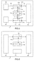
- Fig. 5 schematically illustrates the interceptor modules in a testing mode according to the embodiment of Fig. 2 .
- This example shows the testing of component 3b in relation with components 3a and 3d of Fig. 1 .
- a first testing thread 23a of a first interceptor module 11a connected to a component 3b under test is adapted to perform a blocked read on the destination port 31a connected to the testing means 13b.
- This channel is used to introduce testing packets from the testing means 13b into the component 3b under test.
- the thread 23a sleeps as long as no data has been sent to the queuing channel.
- the first testing thread 23a becomes active, reads the testing packets from the queuing port 31a and transfers them to the source port 31b connected to the component 3b under test.
- a second testing thread 23c of a second interceptor module 11c connected to the component 3b under test is adapted to transmit an output result from said component 3b under test into the testing means 13b.
- This second testing thread 23c is adapted to perform a blocked read on the destination port 31c of the queuing channel connected to the sender component 3b. Since this second testing thread 23c performs also a blocked read, it sleeps until data becomes available in the channel. Once it becomes available, the second testing thread 23c transmits this data to the source port 31d connected to the testing means 13b which is configured to test the reaction of the component 3b under test by analysing the output result.
- the testing means 13b is configured to orchestrate the control of all interceptor modules implicated on the input and output communication channels in order to conduct different testing scenarios.
- components 3a and 3d may send data to component 3b, via interceptor modules 11a and 11d respectively.
- the output of the component 3b can be observed via interceptor module 11c for the case where the output data are transmitted to component 3d or via the interceptor module 11b for the case where the output data are transmitted to component 3a.
- Fig. 6 schematically illustrates the interceptor modules in an observation mode according to the embodiment of Fig. 2 .
- the observing thread 25 of an interceptor module 11a is adapted to stay in a sleep state as long as no data is available and to transmit data from the sender component 3a into the receiver component 3b as well as to the testing means 13b when data becomes available.
- the testing means 13b is configured to observe the data flow between the sender 3a and receiver 3b components.
- the interceptor module's functionality is realised by re-implementing the queuing ports.
- the control means 13a are configured to reroute a traffic flow by specific flags in order to put an interceptor module 11a-11h in a transmitting mode, or an observation mode, or a testing mode.
- the flag enables the interceptor module to re-route the traffic originally sent to another component towards the testing means 13b.
- control means 13a are configured to put all interceptor modules 11a-11h in the same operational mode or to put different interceptor modules in different operational modes.
- FIG. 7 schematically illustrates a chain of components under test according to an embodiment of the present invention.
- This example shows that two interceptor modules 11b, 11g are in the test mode while a third interceptor module 11d in the transmitting mode.
- the interceptor modules are adapted to intercept the communication between multiple components 3a-3f in the platform 1 and thus, it is possible to operate some interceptor modules in a transmitting mode, some others in a testing mode and still some others in an observation mode. This configuration allows testing the correct integration of a subset of the components by creating chains of components under test.
- the different queuing ports and interceptor modules are implemented in software. However, it is also possible to transfer some parts of these elements into hardware.
- the QMan of the P4080 Data Path Acceleration Architecture DPAA
- DPAA Data Path Acceleration Architecture
- the destination of such a FIFO queue is provided by an ID in the software queuing command to the hardware element.
- the QMan may be used to implement the functionality of the Queuing Port. Changing the destination IDs in the queue command enables to implement the intercepting module's functionality by routing the data packets in the hardware FIFO to the analysing means.
- the virtualisation platform according to the present invention is advantageously used in an embedded infrastructure.
- it is adapted to be used in an aircraft communication system in which the different components, intercepting modules and analysing means are connected by queuing ports of an avionic network of for example ARINC-653 or AFDX type.
- the virtualisation platform provides a transparent testing technology allowing testing the components locally in their integrated system context. This approach fulfils the avionic requirements and can be easily deactivated for in-flight operations by putting all the interceptor modules in a transmitting mode. Also it provides systematic means to set clearly test points without interfering or perturbing the applications running on the different components.
Landscapes
- Engineering & Computer Science (AREA)
- Theoretical Computer Science (AREA)
- General Engineering & Computer Science (AREA)
- Computer Hardware Design (AREA)
- Computer Security & Cryptography (AREA)
- Software Systems (AREA)
- General Physics & Mathematics (AREA)
- Physics & Mathematics (AREA)
- Quality & Reliability (AREA)
- Computing Systems (AREA)
- General Health & Medical Sciences (AREA)
- Bioethics (AREA)
- Health & Medical Sciences (AREA)
- Computer Networks & Wireless Communication (AREA)
- Signal Processing (AREA)
- Data Exchanges In Wide-Area Networks (AREA)
- Mobile Radio Communication Systems (AREA)
- Test And Diagnosis Of Digital Computers (AREA)
Abstract
- integrated interceptor modules (11a, 11b) connected to said components (3a, 3b) via communication channels (15), each interceptor module being interposed in the communication channel connecting two components, and
- integrated analysing means (13) connected to said interceptor modules (11a, 11b) and comprising control means (13a) and testing means (13b), said control means being configured to put each interceptor module in an operational mode selected out of a set of predetermined operational modes including a testing mode, and said testing means (13b) being configured to locally test the components connected to the interceptor modules being put in the testing mode.
Description
- The present invention generally concerns testing integrated independent levels of security components hosted on a virtualisation platform and particularly in embedded infrastructures.
- In most industrial fields, it is frequent to have different systems with different applications communicating with each other in order to achieve an assignment. Each application may be considered as a set of functions and each function is a piece of software contributing to execute a part of the task to be accomplished by the application. For example, many different types of equipment in a vehicle or an aircraft need to exchange data with each other through a communication system in order to accomplish the manoeuvring of the vehicle or the aircraft.
- Due to the current growing efficiency of computing resources, the trend consists of putting several applications or functions on the same computer platform in order to use the full computing power and memory storage capabilities offered by that platform. This enables to avoid wasting unused resources and thus reduces the production costs as well as the overall weight of the system, which is particularly advantageous in embedded infrastructures for an aircraft, a satellite or a vehicle. This architecture has however the disadvantage of facilitating the propagation of errors. Thus, security means are provided to prevent any design or implementation error on one part of the system from impacting other parts of the system. The system needs also to be protected against deliberate malicious attacks coming from within the system.
- This difficulty can be solved by existing security architectures such as MILS (Multiple Independent Levels of Security) built upon strict segregation properties for the execution environments and strict communication paths.
- In particular, the functions in a computer system are implemented out of a composition of various more or less loosely coupled sub-functions. For designing a MILS computer system, this approach of loosely-coupled components is valuable. Indeed, splitting a complex system into small components allows defining requirements for these components and enforcing their correct and secure implementation locally. For achieving the complex function again, the components are put together on a same hardware platform. Usually a special operating system (for example, a separation kernel), provides isolated runtime environments, called partitions, for the components. The separation kernel realises a non-interference property between the different components of the platform. For still allowing communication between partitions, the separation kernel also provides specific channels for an inter-partition communication. The communication channels are controlled and the information flow flowing through them is enforced by a system-wide information flow policy. Both the concept of separation and the concept of controlled information flow between the separated components are the major properties of a MILS system.
-
Fig. 8 schematically illustrates an example of aMILS system 101 comprisingMILS components 103a-103e according to the prior art. -
MILS components 103a-103f compriseapplication partitions 103a-103d, an I/O partition 103e and anexternal communication interface 103f. The different components operate together via thecommunication channels 107 of the underlying separation kernel to finally fulfil the system's purpose. The different components communicate via predefined communication paths. There are three different types of communication paths that can be distinguished in a MILS system. These paths consist of an external communication interface, an inter-partition communication interface and communication interface via an I/O partition. The communication between a partition and anexternal communication interface 103f may be realised via adevice driver 109. - Currently, a MILS system is first tested during its development and then by observing its output through external interfaces. In other words, testing of a MILS system currently comprises two kinds of tests. A component or application test in which each application hosted by a partition is tested externally in a stand-alone manner, outside of the context of the MILS system. The second test is an integration test in which the correct behaviour of the integrated MILS system is tested by observing the overall system's output to a given input.
- However, the known methods do not allow a systematic testing approach. In particular, the prior art methods cannot test the components' reaction while they are already deployed in the MILS system.
- Moreover, in certain domains such as in aeronautics, the needs are dictated by particularly severe constraints of reliability and security. In particular, there exist specific requirements that do not allow any system configuration changes between a system under evaluation and the finally deployed in-flight system. Thus, any testing means cannot be removed after the system has been certified.
- The purpose of the present invention is therefore to propose a method and a system for locally testing components in their integrated context on a partitioned type platform (for example MILS) and particularly adapted to be systematically used in an embedded environment like avionics without having the aforementioned shortcomings.
- The present invention is defined by a virtualisation platform (for example of MILS type) comprising a plurality of integrated independent levels of security components (hereafter called components) interconnected via communication channels, said virtualization platform further comprising:
- integrated interceptor modules connected to said components via said communication channels, each interceptor module being interposed in the communication channel connecting two components, and
- integrated analysing means connected to said interceptor modules and comprising control means and testing means, said control means being configured to put each interceptor module in an operational mode selected out of a set of predetermined operational modes including a testing mode, and said testing means being configured to locally test the components connected to the interceptor modules being put in the testing mode.
- Thus the virtualisation platform according to the present invention provides a systematic and transparent testing of the local behaviour and reaction of some or all components in their integrated context i.e., while they are deployed in the virtualisation platform and without any interference.
- The present invention concerns also an embedded infrastructure (for example, a computer) comprising said virtualisation platform according to the above characteristics.
- In addition, the invention concerns an aircraft communication system comprising an avionic network and an embedded infrastructure according to the above characteristics, the components, interceptor modules, and analysing means being interconnected via said avionic network.
- Moreover, the invention concerns a method for testing integrated independent levels of security components on a virtualisation platform, said components being interconnected via communication channels, said method comprising the following steps:
- interposing interceptor modules in the communication channels connecting different components,
- putting each interceptor module in an operational mode selected out of a set of predetermined operational modes including a testing mode, and
- testing locally the components connected to the interceptor modules being put in the testing mode.
- Other characteristics and advantages of the invention will become apparent on reading preferred embodiments of the invention given with reference to the appended figures amongst which:
-
Fig. 1 schematically illustrates a virtualisation platform comprising integrated independent levels of security components according to an embodiment of the invention; -
Fig. 2 schematically illustrates a communication interface between two components of the virtualisation platform demonstrating a method for testing the components according to an embodiment of the invention; -
Fig. 3 schematically illustrates an interceptor module implemented by a set of threads according to one embodiment of the invention; -
Fig. 4 schematically illustrates the interceptor modules in a transmitting mode according to the embodiment ofFig. 2 ; -
Fig. 5 schematically illustrates the interceptor modules in a testing mode according to the embodiment ofFig. 2 ; -
Fig. 6 schematically illustrates the interceptor modules in an observation mode according to the embodiment ofFig. 2 ; -
Fig. 7 schematically illustrates a chain of components under test according to an embodiment of the present invention; and -
Fig. 8 schematically illustrates an example of a MILS system comprising MILS components according to the prior art. - The concept of the invention consists of integrating transparent interception means in the communication channels of a MILS type platform enabling to locally test the components of the platform.
-
Fig. 1 schematically illustrates a virtualisation platform 1 comprising integrated independent levels of security components according to an embodiment of the invention. - The integrated independent levels of
security components 3a-3f (hereafter called components) compriseapplication partitions 3a-3c, input-output partitions 3d, andexternal communication interfaces application partitions 3a-3c, one input-output partition 3d, and twoexternal communication interfaces - Each component has a well specified function and is adapted to communicate with other predefined components. For example, each one of
components 3a-3d has a well definedinterface 5a-5d for communicating with other well identified components to which it is authorised to do so viacommunication channels 15. - Indeed, the
different components 3a-3f operate together via thecommunication channels 15 of the underlying platform 1. They communicate via predefined communication paths comprising external communication interfaces, inter-partition communication interfaces and communication interface via an input-output I/O partition. An instantiation of the virtualisation platform normally uses a combination of these different communication paths. On the other hand, the communication between acomponent 3a-3d and anexternal communication interface 3e may be realised via adevice driver 9. - All elements (3a-3f and 9) are hosted by a virtualisation platform. It is recalled that a virtualisation platform of MILS type, developed for high assurance needs, is based essentially on strict segregation and non-interference properties between the different functions. Indeed, a virtualisation platform 1 offers the possibility to create isolated runtime environments (i.e., partitions) for each function. It also offers strong temporal and spatial segregation between the partitions (i.e. non-interference properties between hardware and software resources shared by the different functions). Moreover, it provides secure communication means between different partitions hosted by the platform as well as secure communication means (for example, network interfaces) between one or more partitions of the platform and outside domains.
- A virtualisation platform 1 can be built by using software and/or hardware virtualisation techniques such as a MILS Separation Kernel or any other virtualisation Operating System fulfilling the above properties. The hardware part of the platform comprises as usual communicating buses (not shown) interconnecting one or more processing units (not shown), storage devices (not shown), and one or more (sometimes virtualized) network interfaces (not shown) as well as a specific hardware module (not shown) for managing direct memory access such as an IOMMU (Input Output Management Memory Unit).
- According to the invention, the virtualisation platform 1 comprises integrated
interceptor modules 11a-11h (or shims) and an integrated analysingmeans 13. - The architecture of
Fig. 1 shows a set ofintegrated interceptor modules 11a-11h connected todifferent components 3a-3f of the platform 1 via thecommunication channels 15. Eachinterceptor module 11a-11h is interposed in acommunication channel 15 connecting two components. The example ofFig. 1 shows that the interceptor modules are paired up intodifferent couples 111a-111d allowing bidirectional communication between the different components. - The integrated analysing
means 13 is connected to theinterceptor modules 11a-11h via a control andcommunication channel 7. It coordinates between theinterceptor modules 11a-11h and thecomponents 3a-3f and it orchestrates the stimulus and test evaluation of each component. - In particular, the analysing
means 13 comprises control means 13a and testing means 13b. The control means 13a are configured to put eachinterceptor module 11a-11h in an operational mode selected out of a set of predetermined operational modes including a testing mode. The testing means 13b are configured to locally test the component orcomponents 3a-3d connected to theinterceptor modules 11a-11h being put in the testing mode. - According to one embodiment, each interceptor module is configured to run isolated in its own resource partition. As a variant, an interceptor module may also be combined with the integrated analysing
means 13 or with other partitions. - Advantageously, the set of predetermined operational modes comprises three modes: testing mode, transmitting mode and observation mode. Thus, any
interceptor module 11a-11h can be put in either one of these three modes. The testing mode enables to test the behaviour and reaction ofcomponents 3a-3d by re-routing the communication traffic towards the testing means 13b and modifying this traffic according to testing procedures. In a transmitting mode, theinterceptor module 11a-11h forwards all traffic to the intended destination component enabling the components to operate in a normal way. Finally, the observation mode enables only to passively listen to the communication between twocomponents 3a-3f without any modification of the normal traffic. -
Fig. 2 schematically illustrates a communication interface between two components of the virtualisation platform demonstrating a method for testing the components according to an embodiment of the invention. - For simplicity reasons, this example only shows a
first component 3a and asecond component 3b hosted by a virtualisation platform 1 and connected to each other viacommunication channels 15. Each component may be an application partition, an input-output partition, or an external communication interface connected to a driver device 9 (seeFig. 1 ). - The method consists in incorporating interception and analysing logic into the virtualisation platform in order to intercept traffic and analyse the different components' behaviour.
- In particular, a couple of first and
second interceptor modules communication channels 15 connecting the twocomponents Interceptor module 11a is integrated in afirst communication channel 15a connecting thesender 3a andreceiver 3b components, whileinterceptor module 11b is integrated in asecond communication channel 15b connecting thesender 3b and thereceiver 3a components. - Moreover, an analysing
means 13 comprising a controlling means 13a and a testing means 13b is integrated in the platform 1 and is connected to the first andsecond interceptor modules communication channels 7. - Each interceptor module is controlled by the controlling means 13a and is put in an operational mode selected out of a set of predetermined operational modes comprising a testing mode, a transmitting mode and an observation mode.
- At least one component is locally tested by the testing means 13b when the
interceptor modules Fig. 5 ). - Advantageously, the implementation of each interceptor module is made small, fast and responsive by using small sequences of code instructions.
- Indeed,
Fig. 3 schematically illustrates an interceptor module implemented by a set of threads according to one embodiment of the invention. - According to this embodiment, each interceptor module 3 is implemented by multiple threads comprising a transmitting
thread 21, first andsecond testing threads thread 25. - The transmitting
thread 21 is adapted to transmit data from asender component 3a to areceiver component 3b. Thefirst testing thread 23a is adapted to transmit data from the analysing means 13 into areceiver component 3b. Thesecond testing thread 23b is adapted to transmit data from a sender component into the analysingmeans 13. Finally, the observingthread 25 is adapted to send data from asender component 3a into areceiver component 3b as well as into the analysingmeans 13b. - For each interceptor module 11 the control means 13a is configured to switch between the different threads 21-25 in order to put the interceptor module 11 in a transmitting mode by activating the transmitting
thread 21, or a testing mode by activating at least onetesting thread thread 25. - For example, in an avionic environment, the
different components 3a-3f,interceptor modules 11a-11h and analysingmeans 13 can be connected by ARINC-653 queuing ports. The queuing ports are implemented by the operating system in a way that data transmitted to a channel by one partition flows non-interfered to the destination partition according to a FIFO queuing operation. -
Fig. 4 schematically illustrates the interceptor modules in a transmitting mode according to the embodiment ofFig. 2 . - In the transmitting or normal mode, the transmitting
thread 21 is configured to perform a blocked read on the destination port of the queuing channel connected to the sender'scomponent 3a. It is thus adapted to stay in a sleep state as long as no data is available (i.e., as long as no data is sent to the queuing channel). As soon as data becomes available, the transmittingthread 21 becomes activated and is then adapted to read the data from the queuing port (sent by thesender component 3a) and to transmit it to the source port of the channel connected to thedestination component 3b. -
Fig. 5 schematically illustrates the interceptor modules in a testing mode according to the embodiment ofFig. 2 . This example shows the testing ofcomponent 3b in relation withcomponents Fig. 1 . - In the testing mode, a
first testing thread 23a of afirst interceptor module 11a connected to acomponent 3b under test is adapted to perform a blocked read on thedestination port 31a connected to the testing means 13b. This channel is used to introduce testing packets from the testing means 13b into thecomponent 3b under test. Thethread 23a sleeps as long as no data has been sent to the queuing channel. When the testing packets become available, thefirst testing thread 23a becomes active, reads the testing packets from the queuingport 31a and transfers them to thesource port 31b connected to thecomponent 3b under test. - A
second testing thread 23c of asecond interceptor module 11c connected to thecomponent 3b under test is adapted to transmit an output result from saidcomponent 3b under test into the testing means 13b. Thissecond testing thread 23c is adapted to perform a blocked read on thedestination port 31c of the queuing channel connected to thesender component 3b. Since thissecond testing thread 23c performs also a blocked read, it sleeps until data becomes available in the channel. Once it becomes available, thesecond testing thread 23c transmits this data to thesource port 31d connected to the testing means 13b which is configured to test the reaction of thecomponent 3b under test by analysing the output result. - More generally, in the case where the component under
test 3b has several inputs and outputs, possibly coming from or going to multiple components, the testing means 13b is configured to orchestrate the control of all interceptor modules implicated on the input and output communication channels in order to conduct different testing scenarios. For example, in reference toFig. 1 ,components component 3b, viainterceptor modules component 3b can be observed viainterceptor module 11c for the case where the output data are transmitted tocomponent 3d or via theinterceptor module 11b for the case where the output data are transmitted tocomponent 3a. -
Fig. 6 schematically illustrates the interceptor modules in an observation mode according to the embodiment ofFig. 2 . - In the observation mode, the observing
thread 25 of aninterceptor module 11a is adapted to stay in a sleep state as long as no data is available and to transmit data from thesender component 3a into thereceiver component 3b as well as to the testing means 13b when data becomes available. The testing means 13b is configured to observe the data flow between thesender 3a andreceiver 3b components. - According to another embodiment, the interceptor module's functionality is realised by re-implementing the queuing ports. The control means 13a are configured to reroute a traffic flow by specific flags in order to put an
interceptor module 11a-11h in a transmitting mode, or an observation mode, or a testing mode. The flag enables the interceptor module to re-route the traffic originally sent to another component towards the testing means 13b. This embodiment reduces the overhead configuration and the number of partitions. However, some critical parts of the operating system need to be re-implemented. - In other respects, it is to be noted that the control means 13a are configured to put all
interceptor modules 11a-11h in the same operational mode or to put different interceptor modules in different operational modes. - Indeed,
Fig. 7 schematically illustrates a chain of components under test according to an embodiment of the present invention. - This example shows that two
interceptor modules third interceptor module 11d in the transmitting mode. Indeed, the interceptor modules are adapted to intercept the communication betweenmultiple components 3a-3f in the platform 1 and thus, it is possible to operate some interceptor modules in a transmitting mode, some others in a testing mode and still some others in an observation mode. This configuration allows testing the correct integration of a subset of the components by creating chains of components under test. - Advantageously, the different queuing ports and interceptor modules are implemented in software. However, it is also possible to transfer some parts of these elements into hardware. For example, the QMan of the P4080 Data Path Acceleration Architecture (DPAA) is adapted to be operated as hardware FIFOs. The destination of such a FIFO queue is provided by an ID in the software queuing command to the hardware element. Thus, the QMan may be used to implement the functionality of the Queuing Port. Changing the destination IDs in the queue command enables to implement the intercepting module's functionality by routing the data packets in the hardware FIFO to the analysing means.
- The virtualisation platform according to the present invention is advantageously used in an embedded infrastructure. In particular, it is adapted to be used in an aircraft communication system in which the different components, intercepting modules and analysing means are connected by queuing ports of an avionic network of for example ARINC-653 or AFDX type.
- The virtualisation platform according to the present invention provides a transparent testing technology allowing testing the components locally in their integrated system context. This approach fulfils the avionic requirements and can be easily deactivated for in-flight operations by putting all the interceptor modules in a transmitting mode. Also it provides systematic means to set clearly test points without interfering or perturbing the applications running on the different components.
Claims (13)
- A virtualisation platform comprising a plurality of integrated independent levels of security components, hereafter called components 3a-3f, interconnected via communication channels (15), characterised in that said virtualization platform (1) further comprises:- integrated interceptor modules (11a-11h) connected to said components (3a-3f) via said communication channels (15), each interceptor module being interposed in the communication channel connecting two components, and- integrated analysing means (13) connected to said interceptor modules (11a-11h) and comprising control means (13a) and testing means (13b), said control means being configured to put each interceptor module in an operational mode selected out of a set of predetermined operational modes including a testing mode, and said testing means (13b) being configured to locally test the components connected to the interceptor modules being put in the testing mode.
- The virtualisation platform according to claim 1, characterised in that said set of predetermined operational modes further comprises a transmitting mode and an observation mode.
- The virtualisation platform according to claim 1 or 2, characterised in that said control means (13a) being configured to put all interceptor modules (11a-11h) in the same operational mode or to put different interceptor modules in different operational modes.
- The virtualisation platform according to anyone of the preceding claims, characterised in that each interceptor module (11a-11h) is implemented by multiple threads comprising a transmitting thread (21) adapted to transmit data from a sender component to a receiver component, a first testing thread (23a) adapted to transmit data from said analysing means (13) to a receiver component, a second testing thread (23b) adapted to transmit data from a sender component into said analysing means, and an observing thread (25) adapted to send data from a sender component to a receiver component as well as into said analysing means and such that, for each interceptor module said control means is configured to switch between the different threads in order to put the interceptor module in a transmitting mode by activating the transmitting thread, or a testing mode by activating at least one testing thread, or an observation mode by activating the observing thread.
- The virtualisation platform according to claim 4, characterised in that in a testing mode a first testing thread (23a) of a first interceptor module (11a) connected to a component (3b) under test is adapted to introduce testing packets from the testing means into the component under test, and in that a second testing thread (23c) of a second interceptor module (11c) connected to the component under test is adapted to transmit an output result from said component under test into the testing means, said testing means being configured to test the reaction of the component under test by analysing said output result.
- The virtualisation platform according to claim 4, characterised in that in a transmitting mode said transmitting thread is adapted to stay in a sleep state as long as no data is available and to transmit data from the sender component into the receiver component when data becomes available.
- The virtualisation platform according to claim 4, characterised in that in an observation mode said observing thread is adapted to stay in a sleep state as long as no data is available and to transmit data from the sender component into the receiver component as well as to the testing means when data becomes available, said testing means being configured to observe the data flow between the sender and receiver components.
- The virtualisation platform according to anyone of claims 1 to 3, characterised in that each interceptor module comprises queuing ports and said control means being configured to reroute a traffic flow by specific flags in order to put an interceptor module in a transmitting mode, or an observation mode, or a testing mode.
- The virtualisation platform according to anyone of the preceding claims characterised in that said set of components comprises application partitions, input-output partitions, driver devices and external communication interfaces.
- The virtualisation platform according to anyone of the preceding claims, characterised in that said virtualisation platform is a MILS platform.
- Embedded infrastructure comprising said virtualisation platform according to anyone of the preceding claims.
- Aircraft communication system comprising an avionic network and an embedded infrastructure according to claim 11, characterised in that said components, interceptor modules, and analysing means are interconnected via said avionic network.
- A method for testing integrated independent levels of security components, hereafter called components, on a virtualisation platform, said components being interconnected via communication channels, characterised in that said method comprises the following steps:- interposing interceptor modules in the communication channels connecting different components,- putting each interceptor module in an operational mode selected out of a set of predetermined operational modes including a testing mode, and- testing locally the components connected to the interceptor modules being put in the testing mode.
Priority Applications (3)
| Application Number | Priority Date | Filing Date | Title |
|---|---|---|---|
| EP14158360.9A EP2916229B1 (en) | 2014-03-07 | 2014-03-07 | Testing integrated independent levels of security components hosted on a virtualisation platform |
| US14/638,365 US9747453B2 (en) | 2014-03-07 | 2015-03-04 | Testing integrated independent levels of security components hosted on a virtualization platform |
| CN201510100564.7A CN104899133B (en) | 2014-03-07 | 2015-03-06 | Test resides in the integrated individual secure level component on virtual platform |
Applications Claiming Priority (1)
| Application Number | Priority Date | Filing Date | Title |
|---|---|---|---|
| EP14158360.9A EP2916229B1 (en) | 2014-03-07 | 2014-03-07 | Testing integrated independent levels of security components hosted on a virtualisation platform |
Publications (2)
| Publication Number | Publication Date |
|---|---|
| EP2916229A1 true EP2916229A1 (en) | 2015-09-09 |
| EP2916229B1 EP2916229B1 (en) | 2019-09-04 |
Family
ID=50280140
Family Applications (1)
| Application Number | Title | Priority Date | Filing Date |
|---|---|---|---|
| EP14158360.9A Active EP2916229B1 (en) | 2014-03-07 | 2014-03-07 | Testing integrated independent levels of security components hosted on a virtualisation platform |
Country Status (3)
| Country | Link |
|---|---|
| US (1) | US9747453B2 (en) |
| EP (1) | EP2916229B1 (en) |
| CN (1) | CN104899133B (en) |
Families Citing this family (5)
| Publication number | Priority date | Publication date | Assignee | Title |
|---|---|---|---|---|
| US10069683B2 (en) * | 2013-09-27 | 2018-09-04 | Nxp Usa, Inc. | Apparatus for optimising a configuration of a communications network device |
| GB2532773A (en) | 2014-11-27 | 2016-06-01 | Airbus Operations Sas | Improvements in or relating to avionics networks |
| US10846439B2 (en) * | 2019-06-28 | 2020-11-24 | Intel Corporation | Functional safety over trace-and-debug |
| CN115174611A (en) * | 2022-05-31 | 2022-10-11 | 通号城市轨道交通技术有限公司 | Vehicle-mounted virtualization platform |
| CN118474188B (en) * | 2024-04-25 | 2026-03-10 | 中信银行股份有限公司 | Tenant identification method for multiple systems |
Citations (2)
| Publication number | Priority date | Publication date | Assignee | Title |
|---|---|---|---|---|
| US6823460B1 (en) * | 1999-11-14 | 2004-11-23 | Networks Associates Technology, Inc. | Method and system for intercepting an application program interface |
| US20060129880A1 (en) * | 2004-11-26 | 2006-06-15 | Mauro Arcese | Method and system for injecting faults into a software application |
Family Cites Families (6)
| Publication number | Priority date | Publication date | Assignee | Title |
|---|---|---|---|---|
| US7075285B2 (en) * | 2004-05-12 | 2006-07-11 | Richard Chin | Delay locked loop circuit and method for testing the operability of the circuit |
| US7676608B1 (en) * | 2006-12-12 | 2010-03-09 | Rockwell Collins, Inc. | System for extending Multiple Independent Levels of Security (MILS) partitioning to input/output (I/O) devices |
| EP1959606B1 (en) * | 2007-02-13 | 2012-08-15 | Secunet Security Networks Aktiengesellschaft | Safety unit |
| US8954929B2 (en) * | 2010-03-29 | 2015-02-10 | Microsoft Corporation | Automatically redirecting method calls for unit testing |
| EP4036721B1 (en) * | 2012-06-26 | 2025-03-26 | Lynx Software Technologies Inc. | Systems and methods involving features of hardware virtualization such as separation kernel hypervisors, hypervisors, hypervisor guest context, hypervisor context, rootkit detection prevention and further features |
| US9575542B2 (en) * | 2013-01-31 | 2017-02-21 | Hewlett Packard Enterprise Development Lp | Computer power management |
-
2014
- 2014-03-07 EP EP14158360.9A patent/EP2916229B1/en active Active
-
2015
- 2015-03-04 US US14/638,365 patent/US9747453B2/en not_active Expired - Fee Related
- 2015-03-06 CN CN201510100564.7A patent/CN104899133B/en active Active
Patent Citations (2)
| Publication number | Priority date | Publication date | Assignee | Title |
|---|---|---|---|---|
| US6823460B1 (en) * | 1999-11-14 | 2004-11-23 | Networks Associates Technology, Inc. | Method and system for intercepting an application program interface |
| US20060129880A1 (en) * | 2004-11-26 | 2006-06-15 | Mauro Arcese | Method and system for injecting faults into a software application |
Non-Patent Citations (1)
| Title |
|---|
| MEI-CHEN HSUEH ET AL: "Fault injection techniques and tools", COMPUTER, vol. 30, no. 4, 1 April 1997 (1997-04-01), pages 75 - 82, XP055014400, ISSN: 0018-9162, DOI: 10.1109/2.585157 * |
Also Published As
| Publication number | Publication date |
|---|---|
| US9747453B2 (en) | 2017-08-29 |
| US20150254461A1 (en) | 2015-09-10 |
| EP2916229B1 (en) | 2019-09-04 |
| CN104899133A (en) | 2015-09-09 |
| CN104899133B (en) | 2019-07-23 |
Similar Documents
| Publication | Publication Date | Title |
|---|---|---|
| EP2916229B1 (en) | Testing integrated independent levels of security components hosted on a virtualisation platform | |
| Gaska et al. | Integrated modular avionics-past, present, and future | |
| EP3119063B1 (en) | System and method for a flexible deterministic communications network | |
| EP3074865B1 (en) | Hardware virtualization module for exclusive controlled access to cpu | |
| US11201884B2 (en) | Bus monitoring system for detecting anomalies indicative of malfunctions or cyber-attacks | |
| US8589922B2 (en) | Performance monitor design for counting events generated by thread groups | |
| US10685125B2 (en) | Multiple security level monitor for monitoring a plurality of MIL-STD-1553 buses with multiple independent levels of security | |
| Paulitsch et al. | Mixed-criticality embedded systems--a balance ensuring partitioning and performance | |
| EP2916511B1 (en) | High assurance security gateway interconnecting different domains | |
| Wassel et al. | Networks on chip with provable security properties | |
| CN111033485B (en) | Method for filtering communication data arriving via a communication connection in a data processing device, data processing device and motor vehicle | |
| US20220164485A1 (en) | Method and configurable hardware module for monitoring a hardware-application | |
| Fohler et al. | Evaluation of DREAMS resource management solutions on a mixed-critical demonstrator | |
| US10243988B2 (en) | Configurable network security | |
| KR20240132033A (en) | Hierarchical hardware-software partitioning and configuration | |
| US10162986B2 (en) | Techniques of improving KVM security under KVM sharing | |
| Avramenko et al. | RTOS solution for noc-based COTS MPSoC usage in mixed-criticality systems | |
| US9659192B1 (en) | Secure deterministic fabric switch system and method | |
| Muench et al. | IOMPU: Spatial separation for hardware-based I/O virtualization for mixed-criticality embedded real-time systems using non-transparent bridges | |
| US20170153988A1 (en) | Integrated circuit security | |
| EP2983088A1 (en) | Memory protection unit | |
| Weissman | MLS-PCA: A high assurance security architecture for future avionics | |
| Nguyen | A Study of covert communications in space platforms hosting government payloads | |
| RU209597U1 (en) | On-board switch with reconfiguration function | |
| US9459891B1 (en) | Interface for interpartition and interprocessor communication |
Legal Events
| Date | Code | Title | Description |
|---|---|---|---|
| PUAI | Public reference made under article 153(3) epc to a published international application that has entered the european phase |
Free format text: ORIGINAL CODE: 0009012 |
|
| AK | Designated contracting states |
Kind code of ref document: A1 Designated state(s): AL AT BE BG CH CY CZ DE DK EE ES FI FR GB GR HR HU IE IS IT LI LT LU LV MC MK MT NL NO PL PT RO RS SE SI SK SM TR |
|
| AX | Request for extension of the european patent |
Extension state: BA ME |
|
| 17P | Request for examination filed |
Effective date: 20151026 |
|
| RBV | Designated contracting states (corrected) |
Designated state(s): AL AT BE BG CH CY CZ DE DK EE ES FI FR GB GR HR HU IE IS IT LI LT LU LV MC MK MT NL NO PL PT RO RS SE SI SK SM TR |
|
| GRAP | Despatch of communication of intention to grant a patent |
Free format text: ORIGINAL CODE: EPIDOSNIGR1 |
|
| RIC1 | Information provided on ipc code assigned before grant |
Ipc: G06F 11/36 20060101AFI20190225BHEP Ipc: G06F 21/57 20130101ALI20190225BHEP Ipc: G06F 11/30 20060101ALI20190225BHEP |
|
| STAA | Information on the status of an ep patent application or granted ep patent |
Free format text: STATUS: GRANT OF PATENT IS INTENDED |
|
| INTG | Intention to grant announced |
Effective date: 20190404 |
|
| GRAS | Grant fee paid |
Free format text: ORIGINAL CODE: EPIDOSNIGR3 |
|
| GRAA | (expected) grant |
Free format text: ORIGINAL CODE: 0009210 |
|
| STAA | Information on the status of an ep patent application or granted ep patent |
Free format text: STATUS: THE PATENT HAS BEEN GRANTED |
|
| AK | Designated contracting states |
Kind code of ref document: B1 Designated state(s): AL AT BE BG CH CY CZ DE DK EE ES FI FR GB GR HR HU IE IS IT LI LT LU LV MC MK MT NL NO PL PT RO RS SE SI SK SM TR |
|
| REG | Reference to a national code |
Ref country code: GB Ref legal event code: FG4D |
|
| REG | Reference to a national code |
Ref country code: CH Ref legal event code: EP |
|
| REG | Reference to a national code |
Ref country code: AT Ref legal event code: REF Ref document number: 1176357 Country of ref document: AT Kind code of ref document: T Effective date: 20190915 |
|
| REG | Reference to a national code |
Ref country code: DE Ref legal event code: R096 Ref document number: 602014052828 Country of ref document: DE |
|
| REG | Reference to a national code |
Ref country code: IE Ref legal event code: FG4D |
|
| REG | Reference to a national code |
Ref country code: NL Ref legal event code: MP Effective date: 20190904 |
|
| REG | Reference to a national code |
Ref country code: LT Ref legal event code: MG4D |
|
| PG25 | Lapsed in a contracting state [announced via postgrant information from national office to epo] |
Ref country code: LT Free format text: LAPSE BECAUSE OF FAILURE TO SUBMIT A TRANSLATION OF THE DESCRIPTION OR TO PAY THE FEE WITHIN THE PRESCRIBED TIME-LIMIT Effective date: 20190904 Ref country code: HR Free format text: LAPSE BECAUSE OF FAILURE TO SUBMIT A TRANSLATION OF THE DESCRIPTION OR TO PAY THE FEE WITHIN THE PRESCRIBED TIME-LIMIT Effective date: 20190904 Ref country code: SE Free format text: LAPSE BECAUSE OF FAILURE TO SUBMIT A TRANSLATION OF THE DESCRIPTION OR TO PAY THE FEE WITHIN THE PRESCRIBED TIME-LIMIT Effective date: 20190904 Ref country code: FI Free format text: LAPSE BECAUSE OF FAILURE TO SUBMIT A TRANSLATION OF THE DESCRIPTION OR TO PAY THE FEE WITHIN THE PRESCRIBED TIME-LIMIT Effective date: 20190904 Ref country code: NO Free format text: LAPSE BECAUSE OF FAILURE TO SUBMIT A TRANSLATION OF THE DESCRIPTION OR TO PAY THE FEE WITHIN THE PRESCRIBED TIME-LIMIT Effective date: 20191204 Ref country code: BG Free format text: LAPSE BECAUSE OF FAILURE TO SUBMIT A TRANSLATION OF THE DESCRIPTION OR TO PAY THE FEE WITHIN THE PRESCRIBED TIME-LIMIT Effective date: 20191204 |
|
| PG25 | Lapsed in a contracting state [announced via postgrant information from national office to epo] |
Ref country code: RS Free format text: LAPSE BECAUSE OF FAILURE TO SUBMIT A TRANSLATION OF THE DESCRIPTION OR TO PAY THE FEE WITHIN THE PRESCRIBED TIME-LIMIT Effective date: 20190904 Ref country code: LV Free format text: LAPSE BECAUSE OF FAILURE TO SUBMIT A TRANSLATION OF THE DESCRIPTION OR TO PAY THE FEE WITHIN THE PRESCRIBED TIME-LIMIT Effective date: 20190904 Ref country code: AL Free format text: LAPSE BECAUSE OF FAILURE TO SUBMIT A TRANSLATION OF THE DESCRIPTION OR TO PAY THE FEE WITHIN THE PRESCRIBED TIME-LIMIT Effective date: 20190904 Ref country code: ES Free format text: LAPSE BECAUSE OF FAILURE TO SUBMIT A TRANSLATION OF THE DESCRIPTION OR TO PAY THE FEE WITHIN THE PRESCRIBED TIME-LIMIT Effective date: 20190904 Ref country code: GR Free format text: LAPSE BECAUSE OF FAILURE TO SUBMIT A TRANSLATION OF THE DESCRIPTION OR TO PAY THE FEE WITHIN THE PRESCRIBED TIME-LIMIT Effective date: 20191205 |
|
| REG | Reference to a national code |
Ref country code: AT Ref legal event code: MK05 Ref document number: 1176357 Country of ref document: AT Kind code of ref document: T Effective date: 20190904 |
|
| PG25 | Lapsed in a contracting state [announced via postgrant information from national office to epo] |
Ref country code: NL Free format text: LAPSE BECAUSE OF FAILURE TO SUBMIT A TRANSLATION OF THE DESCRIPTION OR TO PAY THE FEE WITHIN THE PRESCRIBED TIME-LIMIT Effective date: 20190904 Ref country code: AT Free format text: LAPSE BECAUSE OF FAILURE TO SUBMIT A TRANSLATION OF THE DESCRIPTION OR TO PAY THE FEE WITHIN THE PRESCRIBED TIME-LIMIT Effective date: 20190904 Ref country code: EE Free format text: LAPSE BECAUSE OF FAILURE TO SUBMIT A TRANSLATION OF THE DESCRIPTION OR TO PAY THE FEE WITHIN THE PRESCRIBED TIME-LIMIT Effective date: 20190904 Ref country code: PT Free format text: LAPSE BECAUSE OF FAILURE TO SUBMIT A TRANSLATION OF THE DESCRIPTION OR TO PAY THE FEE WITHIN THE PRESCRIBED TIME-LIMIT Effective date: 20200106 Ref country code: PL Free format text: LAPSE BECAUSE OF FAILURE TO SUBMIT A TRANSLATION OF THE DESCRIPTION OR TO PAY THE FEE WITHIN THE PRESCRIBED TIME-LIMIT Effective date: 20190904 Ref country code: RO Free format text: LAPSE BECAUSE OF FAILURE TO SUBMIT A TRANSLATION OF THE DESCRIPTION OR TO PAY THE FEE WITHIN THE PRESCRIBED TIME-LIMIT Effective date: 20190904 Ref country code: IT Free format text: LAPSE BECAUSE OF FAILURE TO SUBMIT A TRANSLATION OF THE DESCRIPTION OR TO PAY THE FEE WITHIN THE PRESCRIBED TIME-LIMIT Effective date: 20190904 |
|
| PG25 | Lapsed in a contracting state [announced via postgrant information from national office to epo] |
Ref country code: SM Free format text: LAPSE BECAUSE OF FAILURE TO SUBMIT A TRANSLATION OF THE DESCRIPTION OR TO PAY THE FEE WITHIN THE PRESCRIBED TIME-LIMIT Effective date: 20190904 Ref country code: IS Free format text: LAPSE BECAUSE OF FAILURE TO SUBMIT A TRANSLATION OF THE DESCRIPTION OR TO PAY THE FEE WITHIN THE PRESCRIBED TIME-LIMIT Effective date: 20200224 Ref country code: CZ Free format text: LAPSE BECAUSE OF FAILURE TO SUBMIT A TRANSLATION OF THE DESCRIPTION OR TO PAY THE FEE WITHIN THE PRESCRIBED TIME-LIMIT Effective date: 20190904 Ref country code: SK Free format text: LAPSE BECAUSE OF FAILURE TO SUBMIT A TRANSLATION OF THE DESCRIPTION OR TO PAY THE FEE WITHIN THE PRESCRIBED TIME-LIMIT Effective date: 20190904 |
|
| REG | Reference to a national code |
Ref country code: DE Ref legal event code: R097 Ref document number: 602014052828 Country of ref document: DE |
|
| PLBE | No opposition filed within time limit |
Free format text: ORIGINAL CODE: 0009261 |
|
| STAA | Information on the status of an ep patent application or granted ep patent |
Free format text: STATUS: NO OPPOSITION FILED WITHIN TIME LIMIT |
|
| PG2D | Information on lapse in contracting state deleted |
Ref country code: IS |
|
| PG25 | Lapsed in a contracting state [announced via postgrant information from national office to epo] |
Ref country code: DK Free format text: LAPSE BECAUSE OF FAILURE TO SUBMIT A TRANSLATION OF THE DESCRIPTION OR TO PAY THE FEE WITHIN THE PRESCRIBED TIME-LIMIT Effective date: 20190904 Ref country code: IS Free format text: LAPSE BECAUSE OF FAILURE TO SUBMIT A TRANSLATION OF THE DESCRIPTION OR TO PAY THE FEE WITHIN THE PRESCRIBED TIME-LIMIT Effective date: 20200105 |
|
| 26N | No opposition filed |
Effective date: 20200605 |
|
| PG25 | Lapsed in a contracting state [announced via postgrant information from national office to epo] |
Ref country code: SI Free format text: LAPSE BECAUSE OF FAILURE TO SUBMIT A TRANSLATION OF THE DESCRIPTION OR TO PAY THE FEE WITHIN THE PRESCRIBED TIME-LIMIT Effective date: 20190904 |
|
| PG25 | Lapsed in a contracting state [announced via postgrant information from national office to epo] |
Ref country code: MC Free format text: LAPSE BECAUSE OF FAILURE TO SUBMIT A TRANSLATION OF THE DESCRIPTION OR TO PAY THE FEE WITHIN THE PRESCRIBED TIME-LIMIT Effective date: 20190904 |
|
| REG | Reference to a national code |
Ref country code: CH Ref legal event code: PL |
|
| REG | Reference to a national code |
Ref country code: BE Ref legal event code: MM Effective date: 20200331 |
|
| PG25 | Lapsed in a contracting state [announced via postgrant information from national office to epo] |
Ref country code: LU Free format text: LAPSE BECAUSE OF NON-PAYMENT OF DUE FEES Effective date: 20200307 |
|
| PG25 | Lapsed in a contracting state [announced via postgrant information from national office to epo] |
Ref country code: IE Free format text: LAPSE BECAUSE OF NON-PAYMENT OF DUE FEES Effective date: 20200307 Ref country code: CH Free format text: LAPSE BECAUSE OF NON-PAYMENT OF DUE FEES Effective date: 20200331 Ref country code: LI Free format text: LAPSE BECAUSE OF NON-PAYMENT OF DUE FEES Effective date: 20200331 |
|
| PG25 | Lapsed in a contracting state [announced via postgrant information from national office to epo] |
Ref country code: BE Free format text: LAPSE BECAUSE OF NON-PAYMENT OF DUE FEES Effective date: 20200331 |
|
| PG25 | Lapsed in a contracting state [announced via postgrant information from national office to epo] |
Ref country code: TR Free format text: LAPSE BECAUSE OF FAILURE TO SUBMIT A TRANSLATION OF THE DESCRIPTION OR TO PAY THE FEE WITHIN THE PRESCRIBED TIME-LIMIT Effective date: 20190904 Ref country code: MT Free format text: LAPSE BECAUSE OF FAILURE TO SUBMIT A TRANSLATION OF THE DESCRIPTION OR TO PAY THE FEE WITHIN THE PRESCRIBED TIME-LIMIT Effective date: 20190904 Ref country code: CY Free format text: LAPSE BECAUSE OF FAILURE TO SUBMIT A TRANSLATION OF THE DESCRIPTION OR TO PAY THE FEE WITHIN THE PRESCRIBED TIME-LIMIT Effective date: 20190904 |
|
| PG25 | Lapsed in a contracting state [announced via postgrant information from national office to epo] |
Ref country code: MK Free format text: LAPSE BECAUSE OF FAILURE TO SUBMIT A TRANSLATION OF THE DESCRIPTION OR TO PAY THE FEE WITHIN THE PRESCRIBED TIME-LIMIT Effective date: 20190904 |
|
| PGFP | Annual fee paid to national office [announced via postgrant information from national office to epo] |
Ref country code: GB Payment date: 20260324 Year of fee payment: 13 |
|
| PGFP | Annual fee paid to national office [announced via postgrant information from national office to epo] |
Ref country code: DE Payment date: 20260319 Year of fee payment: 13 |
|
| PGFP | Annual fee paid to national office [announced via postgrant information from national office to epo] |
Ref country code: FR Payment date: 20260320 Year of fee payment: 13 |