EP2916088A1 - Shelf brackets to conduct electricity to refrigerator shelves - Google Patents
Shelf brackets to conduct electricity to refrigerator shelves Download PDFInfo
- Publication number
- EP2916088A1 EP2916088A1 EP15157674.1A EP15157674A EP2916088A1 EP 2916088 A1 EP2916088 A1 EP 2916088A1 EP 15157674 A EP15157674 A EP 15157674A EP 2916088 A1 EP2916088 A1 EP 2916088A1
- Authority
- EP
- European Patent Office
- Prior art keywords
- shelf
- electrically conductive
- shelf bracket
- conductive material
- bracket
- Prior art date
- Legal status (The legal status is an assumption and is not a legal conclusion. Google has not performed a legal analysis and makes no representation as to the accuracy of the status listed.)
- Granted
Links
Images

Classifications
-
- H—ELECTRICITY
- H01—ELECTRIC ELEMENTS
- H01B—CABLES; CONDUCTORS; INSULATORS; SELECTION OF MATERIALS FOR THEIR CONDUCTIVE, INSULATING OR DIELECTRIC PROPERTIES
- H01B7/00—Insulated conductors or cables characterised by their form
- H01B7/40—Insulated conductors or cables characterised by their form with arrangements for facilitating mounting or securing
-
- F—MECHANICAL ENGINEERING; LIGHTING; HEATING; WEAPONS; BLASTING
- F21—LIGHTING
- F21V—FUNCTIONAL FEATURES OR DETAILS OF LIGHTING DEVICES OR SYSTEMS THEREOF; STRUCTURAL COMBINATIONS OF LIGHTING DEVICES WITH OTHER ARTICLES, NOT OTHERWISE PROVIDED FOR
- F21V33/00—Structural combinations of lighting devices with other articles, not otherwise provided for
- F21V33/0004—Personal or domestic articles
- F21V33/0044—Household appliances, e.g. washing machines or vacuum cleaners
-
- F—MECHANICAL ENGINEERING; LIGHTING; HEATING; WEAPONS; BLASTING
- F25—REFRIGERATION OR COOLING; COMBINED HEATING AND REFRIGERATION SYSTEMS; HEAT PUMP SYSTEMS; MANUFACTURE OR STORAGE OF ICE; LIQUEFACTION SOLIDIFICATION OF GASES
- F25D—REFRIGERATORS; COLD ROOMS; ICE-BOXES; COOLING OR FREEZING APPARATUS NOT OTHERWISE PROVIDED FOR
- F25D23/00—General constructional features
- F25D23/06—Walls
- F25D23/062—Walls defining a cabinet
-
- F—MECHANICAL ENGINEERING; LIGHTING; HEATING; WEAPONS; BLASTING
- F25—REFRIGERATION OR COOLING; COMBINED HEATING AND REFRIGERATION SYSTEMS; HEAT PUMP SYSTEMS; MANUFACTURE OR STORAGE OF ICE; LIQUEFACTION SOLIDIFICATION OF GASES
- F25D—REFRIGERATORS; COLD ROOMS; ICE-BOXES; COOLING OR FREEZING APPARATUS NOT OTHERWISE PROVIDED FOR
- F25D23/00—General constructional features
- F25D23/06—Walls
- F25D23/065—Details
- F25D23/067—Supporting elements
-
- F—MECHANICAL ENGINEERING; LIGHTING; HEATING; WEAPONS; BLASTING
- F25—REFRIGERATION OR COOLING; COMBINED HEATING AND REFRIGERATION SYSTEMS; HEAT PUMP SYSTEMS; MANUFACTURE OR STORAGE OF ICE; LIQUEFACTION SOLIDIFICATION OF GASES
- F25D—REFRIGERATORS; COLD ROOMS; ICE-BOXES; COOLING OR FREEZING APPARATUS NOT OTHERWISE PROVIDED FOR
- F25D25/00—Charging, supporting, and discharging the articles to be cooled
- F25D25/02—Charging, supporting, and discharging the articles to be cooled by shelves
-
- F—MECHANICAL ENGINEERING; LIGHTING; HEATING; WEAPONS; BLASTING
- F25—REFRIGERATION OR COOLING; COMBINED HEATING AND REFRIGERATION SYSTEMS; HEAT PUMP SYSTEMS; MANUFACTURE OR STORAGE OF ICE; LIQUEFACTION SOLIDIFICATION OF GASES
- F25D—REFRIGERATORS; COLD ROOMS; ICE-BOXES; COOLING OR FREEZING APPARATUS NOT OTHERWISE PROVIDED FOR
- F25D27/00—Lighting arrangements
-
- H—ELECTRICITY
- H01—ELECTRIC ELEMENTS
- H01B—CABLES; CONDUCTORS; INSULATORS; SELECTION OF MATERIALS FOR THEIR CONDUCTIVE, INSULATING OR DIELECTRIC PROPERTIES
- H01B9/00—Power cables
- H01B9/006—Constructional features relating to the conductors
-
- F—MECHANICAL ENGINEERING; LIGHTING; HEATING; WEAPONS; BLASTING
- F21—LIGHTING
- F21W—INDEXING SCHEME ASSOCIATED WITH SUBCLASSES F21K, F21L, F21S and F21V, RELATING TO USES OR APPLICATIONS OF LIGHTING DEVICES OR SYSTEMS
- F21W2131/00—Use or application of lighting devices or systems not provided for in codes F21W2102/00-F21W2121/00
- F21W2131/30—Lighting for domestic or personal use
- F21W2131/305—Lighting for domestic or personal use for refrigerators
-
- F—MECHANICAL ENGINEERING; LIGHTING; HEATING; WEAPONS; BLASTING
- F25—REFRIGERATION OR COOLING; COMBINED HEATING AND REFRIGERATION SYSTEMS; HEAT PUMP SYSTEMS; MANUFACTURE OR STORAGE OF ICE; LIQUEFACTION SOLIDIFICATION OF GASES
- F25D—REFRIGERATORS; COLD ROOMS; ICE-BOXES; COOLING OR FREEZING APPARATUS NOT OTHERWISE PROVIDED FOR
- F25D2201/00—Insulation
-
- F—MECHANICAL ENGINEERING; LIGHTING; HEATING; WEAPONS; BLASTING
- F25—REFRIGERATION OR COOLING; COMBINED HEATING AND REFRIGERATION SYSTEMS; HEAT PUMP SYSTEMS; MANUFACTURE OR STORAGE OF ICE; LIQUEFACTION SOLIDIFICATION OF GASES
- F25D—REFRIGERATORS; COLD ROOMS; ICE-BOXES; COOLING OR FREEZING APPARATUS NOT OTHERWISE PROVIDED FOR
- F25D2327/00—Lighting arrangements not provided for in other groups of this subclass
-
- F—MECHANICAL ENGINEERING; LIGHTING; HEATING; WEAPONS; BLASTING
- F25—REFRIGERATION OR COOLING; COMBINED HEATING AND REFRIGERATION SYSTEMS; HEAT PUMP SYSTEMS; MANUFACTURE OR STORAGE OF ICE; LIQUEFACTION SOLIDIFICATION OF GASES
- F25D—REFRIGERATORS; COLD ROOMS; ICE-BOXES; COOLING OR FREEZING APPARATUS NOT OTHERWISE PROVIDED FOR
- F25D2400/00—General features of, or devices for refrigerators, cold rooms, ice-boxes, or for cooling or freezing apparatus not covered by any other subclass
- F25D2400/40—Refrigerating devices characterised by electrical wiring
Definitions
- This disclosure relates generally to refrigerator shelves, and, more particularly, to shelf brackets to conduct electricity to refrigerator shelves.
- Most refrigerators have one or more shelves that facilitate the storage of items, such as food items.
- the shelves may be made of see-through materials such as glass and acrylic, or non-see-through materials.
- shelves are not lighted, which may impair a user's ease of seeing items stored in the refrigerator.
- lighting inside the refrigerator is mounted high in the refrigerators to provide general illumination within the refrigerator and, thus, may not adequately illuminate the area beneath shelves.
- shelf brackets that conduct electricity to shelves are disclosed. By conducting electricity to shelves, lighting units of the shelves can illuminate the area beneath the shelves to ease the ability of user's seeing the contents of the refrigerator.
- An example shelf bracket includes an end configured to engage a support rail, the end having a first area to conduct electricity from the support rail to the shelf bracket, an arm extending from the end to support the shelf, the arm comprising a second area to conduct electricity from the shelf bracket to the shelf, a non-electrically conductive coating applied to substantially all of the shelf bracket except in the first and second areas, a first electrically conductive material applied to at least a portion of the first area, and a second electrically conductive material applied to at least a portion of the second area, wherein the shelf bracket is formed from a third electrically conductive material, the third electrically conductive material conducts electricity between the first and second areas.
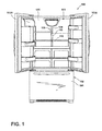
- FIG. 1 illustrates an example refrigerator 100 having a refrigerated compartment 101 and a freezer compartment 102.
- the refrigerated compartment 101 and the freezer compartment 102 each have an open face to provide access to the compartments 101 and 102.
- the refrigerator 100 includes doors 103A and 103B to selectively open and close the open face of the compartment 101, and a drawer 104 moveably mounted to the refrigerator 100 for movement between opened and closed positions to selectively open and close the open face of compartment 102.
- shelf brackets are disclosed herein with reference to the example refrigerator 100 of FIG. 1 , one of ordinary skill in the art will readily appreciate that the shelf brackets disclosed herein may be used to conduct electricity to shelves in refrigerators having other configurations (e.g., a side-by-side refrigerators, a top-freezer refrigerators, etc.), in any other appliances including, but not limited to, a freezer, a washing machine, a dryer, a stove, a microwave, a dishwasher, a shelving unit, a refresher, etc., or in any other apparatus, device, installation, etc. having shelves to which conducting electricity is desired and/or needed.
- refrigerators having other configurations (e.g., a side-by-side refrigerators, a top-freezer refrigerators, etc.), in any other appliances including, but not limited to, a freezer, a washing machine, a dryer, a stove, a microwave, a dishwasher, a shelving unit, a refresher, etc., or in any other apparatus, device, installation, etc. having shelves
- the example refrigerator 100 of FIG. 1 includes one or more shelves (one of which is designated at reference numeral 110).
- the example refrigerator 100 includes a plurality of electrically conductive shelf brackets (one of which is designated at reference numeral 115) configured and constructed in accordance with the teachings of this disclosure.
- the example shelves 110 and shelf brackets 115 of FIG. 1 are moveably positionable within the refrigerator 100 to allow for the flexible storage of items in the refrigerator 100.
- additional and/or alternative configurations may be used.
- not all the shelf brackets 115 need be electrically conductive.
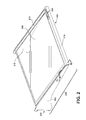
- FIG. 2 is an isometric view of the example shelf 110 of FIG. 1 supported by a pair of the example shelf brackets 115.
- the shelf 110 includes a piece of glass, acrylic, etc. 205 surrounded by a border 210, and trim 215 that runs along the front edge of the shelf 110.
- the glass 205 is affixed to the bracket 115 by an adhesive 305 (see FIG. 3 ).
- a lighting unit 405 is positioned beneath the front edge of the shelf 110.
- the example refrigerator 100 includes a plurality of support rails or ladders (one of which is designated at reference numeral 120).
- the example rails 120 may be mechanically attached to a rear wall 125 of the refrigerator 100, or foamed into the rear wall 125 of the refrigerator 100.
- Ends of the shelf brackets 115 (one of which is designated at reference numeral 220 in FIG. 2 ) mechanically engage slots or openings (one of which is designated at reference numeral 130) in the rails 120.
- the ends 220 of the example shelf brackets 115 may have a notch 310 and a tab 315.
- the shelf bracket 115 includes an arm 225 that extends forward from the end 220 and supports the shelf 110.
- the example rails 120 of FIG. 1 are electrically energized so that electricity may be conducted to the shelf brackets 115. Electricity is conducted to the rails 120 via a terminal (not shown) foamed in the rear wall 125. In some examples, the rails 120 and the shelf brackets 115 conduct low voltage, low power electricity. In some examples, a controller (not shown) detects short conditions and stops the conveyance of electricity to the rails 120 for a pre-defined period of time after the short condition is detected. In the example of FIG. 1 , substantially all exposed surfaces of the rails 120 are coated in a non-electrically conductive material or coating such as plastic, except at unexposed surfaces, areas or points that engage the shelf brackets 115, and conduct electricity to the shelf brackets 115.
- the unexposed surfaces, points or areas of the rails 120 may be masked before the non-electrically conductive material is applied. Additionally and/or alternatively, the non-electrically conductive material may be removed from these unexposed surfaces, areas or points after the non-electrically conductive material or coating is applied. These surfaces, areas or points may be left bare, and/or coated with an electrically conductive material or coating.
- the rails 120 are formed of an electrically conductive material that resists corrosion, or these surfaces, points or areas are at least partially covered in an electrically conductive material that reduces corrosion of the rails 120.
- the example shelf brackets 115 are formed of an electrically conductive material, such as steel, plated steel, a combination of nickel and tin, stainless steel, etc. Substantially all of the shelf brackets 115 are coated in a non-electrically conductive coating or material, such as a paint, a plastic, etc., except at surfaces, points or areas where electricity is intended to be conducted from the rails 120 to the shelf brackets 115, and at surfaces, points or areas where electricity is intended to be conducted from the shelf brackets 115 to the shelves 110 and/or lighting units 405 associated with the shelves 110. As shown in FIG.
- an electrically conductive coating or material 320 may be applied to surfaces, points or areas where an end 220 of a shelf bracket 115 engages a respective rail 120.
- the electrically conductive material from which the shelf brackets 115 are formed is masked at these surfaces, points or areas before the non-electrically conductive material or coating is applied. Additional and/or alternatively, the non-electrically conductive coating or material may be removed to expose these surfaces, areas or points. These surfaces, points or areas may be left bare, or at least partially covered in an electrically conductive coating or material.
- Example electrically conductive materials or coatings 320 include, but are not limited to an adhesive, a glue, a plastic, a nylon, a plating, etc.
- the electrically conductive materials or coatings 320 are selected to reduce or substantially prevent corrosion of the shelf bracket 115.
- the electrically conductive material or coating applied at one end of the shelf bracket 115 may be different from the electrically conductive material or coating applied at an opposite end of the shelf bracket 115.
- areas of the shelf bracket 115 may be left bare at one end while an electrically conductive material or coating applied to an opposite end.
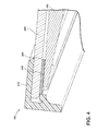
- the example refrigerator 110 of FIG. 1 includes one or more lighting units 405 ( FIG. 4 ) positioned within and/or beneath the shelf 110.
- the lighting unit 405 is positioned beneath the shelf 110 along a front edge of the shelf 110.
- the trim 215 overlaps the front edge of the glass 205.
- the lighting unit 405 is beneath the glass 205 and runs along the front edge of the shelf 110.
- the shelf bracket 115 conducts electricity to the lighting unit 405 via an electrically conductive material or coating 410 applied to the shelf bracket 115.
- the electrically conductive material from which the shelf bracket 115 is formed may be masked to define the area 410 before the non-electrically conductive material or coating is applied. Additionally and/or alternatively, the non-electrically conductive material may be removed from the area 410. The area 410 of the shelf bracket 115 may be left bare or may be covered in an electrically conductive coating or material.
- Example electrically conductive materials or coatings 410 include, but are not limited to an adhesive, a glue, a plastic, a nylon, a plating, etc. In some examples, the electrically conductive material or coating 410 is selected to reduce or substantially prevent corrosion of the shelf bracket 115. While one area 410 of electrically conductive material or coating in FIG. 4 , one or more areas of electrically conductive material or coating may be used.
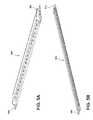
- FIGS. 5A and 5B are isometric views of the example lighting unit 405. As shown in the example FIGS. 5A and 5B , the lighting unit 405 includes metallic tabs 505 and 510 to conduct electricity from the shelf bracket 115 to the lighting unit 405.
- the shelf 110 may additionally or alternatively include a user interface 230 that allows a user to control and/or adjust one or more parameters, variables, etc. that control and/or customize one or more operations of the refrigerator 100.
- the user interface may be used to, for example, control a temperature, select a lighting color, a brightness, etc.
- the user interface 230 may include any number of buttons (e.g., capacitive touch points), displays, indicator lights, etc.
- the example shelf bracket 115 disclosed herein may be used to provide power to the user interface 230 in addition to or instead of the example lighting unit 405.
Landscapes
- Engineering & Computer Science (AREA)
- General Engineering & Computer Science (AREA)
- Chemical & Material Sciences (AREA)
- Combustion & Propulsion (AREA)
- Physics & Mathematics (AREA)
- Mechanical Engineering (AREA)
- Thermal Sciences (AREA)
- Devices That Are Associated With Refrigeration Equipment (AREA)
- Arrangement Of Elements, Cooling, Sealing, Or The Like Of Lighting Devices (AREA)
Abstract
Description
- This disclosure relates generally to refrigerator shelves, and, more particularly, to shelf brackets to conduct electricity to refrigerator shelves. Most refrigerators have one or more shelves that facilitate the storage of items, such as food items. The shelves may be made of see-through materials such as glass and acrylic, or non-see-through materials. In some known refrigerators, shelves are not lighted, which may impair a user's ease of seeing items stored in the refrigerator. In some known refrigerators, lighting inside the refrigerator is mounted high in the refrigerators to provide general illumination within the refrigerator and, thus, may not adequately illuminate the area beneath shelves. To overcome at least these problems, shelf brackets that conduct electricity to shelves are disclosed. By conducting electricity to shelves, lighting units of the shelves can illuminate the area beneath the shelves to ease the ability of user's seeing the contents of the refrigerator.
- Shelf brackets to conduct electricity to refrigerator shelves are disclosed. An example shelf bracket includes an end configured to engage a support rail, the end having a first area to conduct electricity from the support rail to the shelf bracket, an arm extending from the end to support the shelf, the arm comprising a second area to conduct electricity from the shelf bracket to the shelf, a non-electrically conductive coating applied to substantially all of the shelf bracket except in the first and second areas, a first electrically conductive material applied to at least a portion of the first area, and a second electrically conductive material applied to at least a portion of the second area, wherein the shelf bracket is formed from a third electrically conductive material, the third electrically conductive material conducts electricity between the first and second areas.
-
-
FIG. 1 illustrates an example refrigerator having a shelf bracket in accordance with the teachings of this disclosure. -
FIG. 2 is an isometric view of the example shelf ofFIG. 1 . -
FIG. 3 illustrates an example end of the example shelf bracket ofFIGS. 1 and2 . -
FIG. 4 is an isometric cross-section view of the example shelf bracket ofFIGS. 1 and2 taken along line IV-IV ofFIG. 2 . -
FIGS. 5A and 5B are isometric views of the example lighting unit ofFIG. 4 . -
FIG. 1 illustrates anexample refrigerator 100 having a refrigeratedcompartment 101 and afreezer compartment 102. The refrigeratedcompartment 101 and thefreezer compartment 102 each have an open face to provide access to thecompartments refrigerator 100 includesdoors compartment 101, and adrawer 104 moveably mounted to therefrigerator 100 for movement between opened and closed positions to selectively open and close the open face ofcompartment 102. - Although shelf brackets are disclosed herein with reference to the
example refrigerator 100 ofFIG. 1 , one of ordinary skill in the art will readily appreciate that the shelf brackets disclosed herein may be used to conduct electricity to shelves in refrigerators having other configurations (e.g., a side-by-side refrigerators, a top-freezer refrigerators, etc.), in any other appliances including, but not limited to, a freezer, a washing machine, a dryer, a stove, a microwave, a dishwasher, a shelving unit, a refresher, etc., or in any other apparatus, device, installation, etc. having shelves to which conducting electricity is desired and/or needed. - To allow items to be stored in the
refrigerator 100, theexample refrigerator 100 ofFIG. 1 includes one or more shelves (one of which is designated at reference numeral 110). To support and conduct electricity to theexample shelves 110 ofFIG. 1 , theexample refrigerator 100 includes a plurality of electrically conductive shelf brackets (one of which is designated at reference numeral 115) configured and constructed in accordance with the teachings of this disclosure. The example shelves 110 andshelf brackets 115 ofFIG. 1 are moveably positionable within therefrigerator 100 to allow for the flexible storage of items in therefrigerator 100. In the example ofFIG. 1 , there are twoshelf brackets 115 supporting eachshelf 110. However, persons of ordinary skill of art will recognize that additional and/or alternative configurations may be used. Moreover, not all theshelf brackets 115 need be electrically conductive. -
FIG. 2 is an isometric view of theexample shelf 110 ofFIG. 1 supported by a pair of theexample shelf brackets 115. In the illustrated example ofFIG. 2 , theshelf 110 includes a piece of glass, acrylic, etc. 205 surrounded by aborder 210, andtrim 215 that runs along the front edge of theshelf 110. In some examples, theglass 205 is affixed to thebracket 115 by an adhesive 305 (seeFIG. 3 ). As discussed below in connection withFIG. 4 , alighting unit 405 is positioned beneath the front edge of theshelf 110. - Returning to
FIG. 1 , to support theshelf brackets 115, theexample refrigerator 100 includes a plurality of support rails or ladders (one of which is designated at reference numeral 120). Theexample rails 120 may be mechanically attached to arear wall 125 of therefrigerator 100, or foamed into therear wall 125 of therefrigerator 100. Ends of the shelf brackets 115 (one of which is designated atreference numeral 220 inFIG. 2 ) mechanically engage slots or openings (one of which is designated at reference numeral 130) in therails 120. For example, as shown inFIG. 3 , theends 220 of theexample shelf brackets 115 may have anotch 310 and atab 315. Theexample notch 310 ofFIG. 3 engages an edge of an opening orslot 130 in therail 120, and theexample tab 315 engages a back side of therail 120. Persons of ordinary skill in the art will readily appreciate that other openings orshelf bracket 115ends 220 may additionally and/or alternatively be used. As shown inFIG. 2 , theshelf bracket 115 includes anarm 225 that extends forward from theend 220 and supports theshelf 110. - The
example rails 120 ofFIG. 1 are electrically energized so that electricity may be conducted to theshelf brackets 115. Electricity is conducted to therails 120 via a terminal (not shown) foamed in therear wall 125. In some examples, therails 120 and theshelf brackets 115 conduct low voltage, low power electricity. In some examples, a controller (not shown) detects short conditions and stops the conveyance of electricity to therails 120 for a pre-defined period of time after the short condition is detected. In the example ofFIG. 1 , substantially all exposed surfaces of therails 120 are coated in a non-electrically conductive material or coating such as plastic, except at unexposed surfaces, areas or points that engage theshelf brackets 115, and conduct electricity to theshelf brackets 115. The unexposed surfaces, points or areas of therails 120 may be masked before the non-electrically conductive material is applied. Additionally and/or alternatively, the non-electrically conductive material may be removed from these unexposed surfaces, areas or points after the non-electrically conductive material or coating is applied. These surfaces, areas or points may be left bare, and/or coated with an electrically conductive material or coating. In some examples, therails 120 are formed of an electrically conductive material that resists corrosion, or these surfaces, points or areas are at least partially covered in an electrically conductive material that reduces corrosion of therails 120. - To conduct electricity from the
shelf brackets 115 to theshelves 110, theexample shelf brackets 115 are formed of an electrically conductive material, such as steel, plated steel, a combination of nickel and tin, stainless steel, etc. Substantially all of theshelf brackets 115 are coated in a non-electrically conductive coating or material, such as a paint, a plastic, etc., except at surfaces, points or areas where electricity is intended to be conducted from therails 120 to theshelf brackets 115, and at surfaces, points or areas where electricity is intended to be conducted from theshelf brackets 115 to theshelves 110 and/orlighting units 405 associated with theshelves 110. As shown inFIG. 3 , an electrically conductive coating ormaterial 320 may be applied to surfaces, points or areas where anend 220 of ashelf bracket 115 engages arespective rail 120. In some examples, the electrically conductive material from which theshelf brackets 115 are formed is masked at these surfaces, points or areas before the non-electrically conductive material or coating is applied. Additional and/or alternatively, the non-electrically conductive coating or material may be removed to expose these surfaces, areas or points. These surfaces, points or areas may be left bare, or at least partially covered in an electrically conductive coating or material. Example electrically conductive materials orcoatings 320 include, but are not limited to an adhesive, a glue, a plastic, a nylon, a plating, etc. In some examples, the electrically conductive materials orcoatings 320 are selected to reduce or substantially prevent corrosion of theshelf bracket 115. The electrically conductive material or coating applied at one end of theshelf bracket 115 may be different from the electrically conductive material or coating applied at an opposite end of theshelf bracket 115. Moreover, areas of theshelf bracket 115 may be left bare at one end while an electrically conductive material or coating applied to an opposite end. - When electricity is applied to the
shelf bracket 115 by therail 120, electricity passes through theshelf bracket 115 to theshelf 110. Accordingly, an electrical potential difference will form across the length of thearm 225 of theshelf bracket 115. Persons of ordinary skill in the art will readily understand that the electrical potential difference will depend, at least, on the voltage applied to theshelf bracket 115, the current demands of theshelf 110, and the electrical resistance of theshelf bracket 115. - To illuminate a
shelf 110 and/or an area beneath theshelf 110, theexample refrigerator 110 ofFIG. 1 includes one or more lighting units 405 (FIG. 4 ) positioned within and/or beneath theshelf 110. In the example ofFIG. 4 , thelighting unit 405 is positioned beneath theshelf 110 along a front edge of theshelf 110. However, persons of ordinary skill of art will recognize that additional and/or alternative configurations may be used. As shown in the example ofFIG. 4 , the trim 215 overlaps the front edge of theglass 205. Thelighting unit 405 is beneath theglass 205 and runs along the front edge of theshelf 110. Theshelf bracket 115 conducts electricity to thelighting unit 405 via an electrically conductive material orcoating 410 applied to theshelf bracket 115. The electrically conductive material from which theshelf bracket 115 is formed may be masked to define thearea 410 before the non-electrically conductive material or coating is applied. Additionally and/or alternatively, the non-electrically conductive material may be removed from thearea 410. Thearea 410 of theshelf bracket 115 may be left bare or may be covered in an electrically conductive coating or material. Example electrically conductive materials orcoatings 410 include, but are not limited to an adhesive, a glue, a plastic, a nylon, a plating, etc. In some examples, the electrically conductive material orcoating 410 is selected to reduce or substantially prevent corrosion of theshelf bracket 115. While onearea 410 of electrically conductive material or coating inFIG. 4 , one or more areas of electrically conductive material or coating may be used. -
FIGS. 5A and 5B are isometric views of theexample lighting unit 405. As shown in the exampleFIGS. 5A and 5B , thelighting unit 405 includesmetallic tabs shelf bracket 115 to thelighting unit 405. - As shown in
FIG. 2 , theshelf 110 may additionally or alternatively include auser interface 230 that allows a user to control and/or adjust one or more parameters, variables, etc. that control and/or customize one or more operations of therefrigerator 100. For example, the user interface may be used to, for example, control a temperature, select a lighting color, a brightness, etc. Theuser interface 230 may include any number of buttons (e.g., capacitive touch points), displays, indicator lights, etc. Theexample shelf bracket 115 disclosed herein may be used to provide power to theuser interface 230 in addition to or instead of theexample lighting unit 405.
Claims (15)
- A shelf bracket (115) to conduct electricity to a shelf (110) of a refrigerator (100), the shelf bracket (15) comprising:an end (220) configured to engage a support rail (120), wherein the end (220) comprises a first area to conduct electricity from the support rail (120) to the shelf bracket (115);an arm (225) extending from the end (220), wherein the arm (225) is configured to support the shelf (110), and wherein the arm (225) comprises a second area to conduct electricity from the shelf bracket (115) to the shelf (110);a non-electrically conductive coating applied to substantially all of the shelf bracket (115) except in the first and second areas;a first electrically conductive material (320) applied to at least a portion of the first area; anda second electrically conductive material (410) applied to at least a portion of the second area,wherein the shelf bracket (115) is formed from a third electrically conductive material, the third electrically conductive material to conduct electricity between the first and second areas.
- A shelf bracket (115) as defined in claim 1, wherein the second electrically conductive material comprises the first electrically conductive material.
- A shelf bracket (115) as defined in any of claims 1-2, wherein the first area is configured to engage at least one of a surface of the support rail (120) opposite the shelf bracket (115), and/or an edge of an opening (130) defined in the support rail (115).
- A shelf bracket (115) as defined in any of claims 1-3, wherein at least one of the first electrically conductive material and the second electrically conductive material comprises an electrically conductive adhesive.
- A shelf bracket (115) as defined in claim 4, wherein the electrically conductive adhesive is selected to reduce corrosion of the shelf bracket (115).
- A shelf bracket (115) as defined in any one of claims 1-5, wherein the non-electrically conductive coating and the first and second electrically conductive materials (320, 410) are selected to reduce corrosion of the shelf bracket (115).
- A shelf bracket (115) as defined in any one of claims 1-6, wherein the non-electrically conductive coating and the first and second electrically conductive materials comprise a plastic.
- A shelf bracket (115) as defined in any one of claims 1-7, wherein at least one of the first conductive material and the second electrically conductive material comprises at least one of a conductive plating, a conductive plastic, and/or a conductive nylon.
- A shelf bracket (115) as defined in any one of claims 1-8, wherein the non-electrically conductive coating comprises at least one of a plastic and/or a paint.
- A shelf bracket (115) as defined in any one of claims 1-9, wherein the second area conducts electricity to a lighting assembly (405) of the shelf (110).
- A shelf bracket (115) as defined in any one of claims 1-9, wherein the shelf bracket (115) conducts electricity to a lighting assembly (4050 of the shelf (110).
- A shelf bracket (115) as defined in any one of claims 1-11, wherein the shelf bracket (115) conducts electricity to a user interface (230) on the shelf (110).
- A shelf bracket (115) as defined in claim 1, wherein the end (220) is configured to engage an opening (130) defined in the support rail (120), and wherein the end (220) is configured to conduct electricity from the support rail (120) to the shelf bracket (115) via at least one of a surface of the support rail (115) opposite the shelf bracket (115), and/or an edge of the opening (130).
- A shelf bracket (115) as defined in any one of claims 1-13, wherein the third electrically conductive material comprises a plated steel comprising nickel and tin, and/or a stainless steel.
- A shelf bracket (115) as defined in any one of claims 10-11, wherein electricity is conducted to the lighting assembly (405) through metallic tabs (505, 510)at the ends of the lighting assembly (405).
Applications Claiming Priority (1)
| Application Number | Priority Date | Filing Date | Title |
|---|---|---|---|
| US14/195,944 US9287021B2 (en) | 2014-03-04 | 2014-03-04 | Shelf brackets to conduct electricity to refrigerator shelves |
Publications (2)
| Publication Number | Publication Date |
|---|---|
| EP2916088A1 true EP2916088A1 (en) | 2015-09-09 |
| EP2916088B1 EP2916088B1 (en) | 2020-07-08 |
Family
ID=52686125
Family Applications (1)
| Application Number | Title | Priority Date | Filing Date |
|---|---|---|---|
| EP15157674.1A Not-in-force EP2916088B1 (en) | 2014-03-04 | 2015-03-04 | Shelf brackets to conduct electricity to refrigerator shelves |
Country Status (2)
| Country | Link |
|---|---|
| US (2) | US9287021B2 (en) |
| EP (1) | EP2916088B1 (en) |
Cited By (2)
| Publication number | Priority date | Publication date | Assignee | Title |
|---|---|---|---|---|
| US11035531B1 (en) | 2019-10-15 | 2021-06-15 | Sub-Zero Group, Inc. | Shelf light assembly |
| US11221175B1 (en) | 2020-12-18 | 2022-01-11 | Sub-Zero Group, Inc. | Liner hanger |
Families Citing this family (11)
| Publication number | Priority date | Publication date | Assignee | Title |
|---|---|---|---|---|
| KR20240127447A (en) | 2013-06-20 | 2024-08-22 | 젬트론 코포레이션 | Modular luminaires for appliance lighting |
| KR102314317B1 (en) | 2016-01-04 | 2021-10-20 | 엘지전자 주식회사 | refrigerator |
| US10648724B2 (en) * | 2016-09-06 | 2020-05-12 | Whirlpool Corporation | Cold plate shelf assembly for a refrigerator |
| KR102591763B1 (en) * | 2016-11-04 | 2023-10-23 | 삼성전자주식회사 | Refrigerator |
| US9989298B1 (en) * | 2017-02-02 | 2018-06-05 | Haier Us Appliance Solutions, Inc. | Powered adjustable shelf for refrigerator appliance |
| US10948229B2 (en) | 2019-02-12 | 2021-03-16 | Bsh Home Appliances Corporation | Shelf-integrated water dispenser for refrigerator appliance |
| US11109677B2 (en) * | 2019-03-01 | 2021-09-07 | Schott Gemtron Corporation | Shelf assemblies that display illuminated indicia |
| US12290174B2 (en) | 2020-04-24 | 2025-05-06 | Ssw Advanced Technologies, Llc | Illuminated shelf |
| CN113739509A (en) * | 2021-08-31 | 2021-12-03 | 合肥雪祺电气有限公司 | Refrigerator luminous shelf assembly and refrigerator |
| MX2024002924A (en) | 2021-10-15 | 2024-03-27 | Ssw Advanced Tech Llc | Illuminated shelf assemblies. |
| CA3232759A1 (en) | 2021-10-15 | 2023-04-20 | Ssw Advanced Technologies, Llc | Illuminated shelf assemblies |
Citations (4)
| Publication number | Priority date | Publication date | Assignee | Title |
|---|---|---|---|---|
| US5034861A (en) * | 1989-12-22 | 1991-07-23 | Raytheon Company | Shelf track lighting |
| US20080043456A1 (en) * | 2006-08-15 | 2008-02-21 | Bernardini Allen J | Shelf light bracket connector system |
| US20100006519A1 (en) * | 2006-08-03 | 2010-01-14 | Thoth Nv | Shelf for a shelving unit |
| US20100259148A1 (en) * | 2007-07-31 | 2010-10-14 | Electrolux Home Products Corporation N.V. | Food refrigeration appliance with illuminated shelves, and method of producing the illuminated shelves |
Family Cites Families (22)
| Publication number | Priority date | Publication date | Assignee | Title |
|---|---|---|---|---|
| US3506325A (en) | 1968-07-25 | 1970-04-14 | Gen Electric | Refrigerator including illuminated cabinet shelf |
| US4973796A (en) | 1989-08-10 | 1990-11-27 | Visu-Wall By Hbsa Industries, Inc. | Electrified wall structure |
| EP0558305A3 (en) | 1992-02-24 | 1995-07-12 | Clares Regisbrook Systems | Apparatus and method for the supply of power and/or data with shelving systems |
| US5287252A (en) | 1993-01-14 | 1994-02-15 | Sub-Zero Freezer Company, Inc. | Adjustable illuminated refrigerator shelf |
| US5690415A (en) | 1995-11-29 | 1997-11-25 | Stylmark, Inc. | Display light |
| FR2819577B1 (en) | 2001-01-12 | 2003-07-18 | Herger | LED ILLUMINATED SHELF |
| US7260438B2 (en) | 2001-11-20 | 2007-08-21 | Touchsensor Technologies, Llc | Intelligent shelving system |
| DE10202444A1 (en) | 2002-01-22 | 2003-07-31 | Miele & Cie | Refrigeration cabinets, in particular refrigerators |
| US6813896B1 (en) | 2003-07-30 | 2004-11-09 | Whirlpool Corporation | Power bus for removable refrigerator shelves |
| GB0408696D0 (en) | 2004-04-19 | 2004-05-19 | Daniel D | Shelving |
| GB0427835D0 (en) | 2004-12-20 | 2005-01-19 | Artform Internat Ltd | Product display |
| GB0517053D0 (en) | 2005-08-19 | 2005-09-28 | Daniel Charles | Shelving |
| US7748806B2 (en) | 2005-08-29 | 2010-07-06 | Whirlpool Corporation | Encapsulated sliding shelf and over-molded frame |
| US7338180B2 (en) | 2005-12-21 | 2008-03-04 | Whirlpool Corporation | Lighted shelf assembly for a refrigerator |
| JP4739983B2 (en) | 2006-02-22 | 2011-08-03 | 三洋電機株式会社 | Showcase |
| US8453476B2 (en) | 2009-05-21 | 2013-06-04 | Whirlpool Corporation | Refrigerator module mounting system |
| US8360802B2 (en) | 2009-11-12 | 2013-01-29 | Whirlpool Corporation | Adjustable connector system for connection to a modular appliance |
| EP1950514B1 (en) | 2007-01-25 | 2009-09-09 | Electrolux Home Products Corporation N.V. | Food cooling appliance |
| MX2010013340A (en) | 2008-06-04 | 2011-04-26 | Ssw Holding Co Inc | Shelf with led assembly. |
| US8646935B2 (en) | 2009-04-23 | 2014-02-11 | POP Displays USA LLC | Low voltage illumination grid assembly for retail display shelf system |
| US20110273867A1 (en) | 2010-05-05 | 2011-11-10 | Premier Custom Built, Inc. | Adjustable shelves with lighting fixture |
| KR20240127447A (en) | 2013-06-20 | 2024-08-22 | 젬트론 코포레이션 | Modular luminaires for appliance lighting |
-
2014
- 2014-03-04 US US14/195,944 patent/US9287021B2/en active Active
-
2015
- 2015-03-04 EP EP15157674.1A patent/EP2916088B1/en not_active Not-in-force
-
2016
- 2016-01-27 US US15/007,392 patent/US9595373B2/en active Active
Patent Citations (4)
| Publication number | Priority date | Publication date | Assignee | Title |
|---|---|---|---|---|
| US5034861A (en) * | 1989-12-22 | 1991-07-23 | Raytheon Company | Shelf track lighting |
| US20100006519A1 (en) * | 2006-08-03 | 2010-01-14 | Thoth Nv | Shelf for a shelving unit |
| US20080043456A1 (en) * | 2006-08-15 | 2008-02-21 | Bernardini Allen J | Shelf light bracket connector system |
| US20100259148A1 (en) * | 2007-07-31 | 2010-10-14 | Electrolux Home Products Corporation N.V. | Food refrigeration appliance with illuminated shelves, and method of producing the illuminated shelves |
Cited By (3)
| Publication number | Priority date | Publication date | Assignee | Title |
|---|---|---|---|---|
| US11035531B1 (en) | 2019-10-15 | 2021-06-15 | Sub-Zero Group, Inc. | Shelf light assembly |
| US11296433B1 (en) | 2019-10-15 | 2022-04-05 | Sub-Zero Group, Inc. | Shelf with electrical connectivity |
| US11221175B1 (en) | 2020-12-18 | 2022-01-11 | Sub-Zero Group, Inc. | Liner hanger |
Also Published As
| Publication number | Publication date |
|---|---|
| US20160141078A1 (en) | 2016-05-19 |
| US9595373B2 (en) | 2017-03-14 |
| EP2916088B1 (en) | 2020-07-08 |
| US9287021B2 (en) | 2016-03-15 |
| US20150255193A1 (en) | 2015-09-10 |
Similar Documents
| Publication | Publication Date | Title |
|---|---|---|
| EP2916088B1 (en) | Shelf brackets to conduct electricity to refrigerator shelves | |
| EP2778585B1 (en) | Refrigerator with an apparatus to provide lighting | |
| US9541328B2 (en) | Power supplies for lighted shelves in a refrigerator | |
| EP2910881A1 (en) | Lighting units for refrigerator drawers and baskets | |
| EP2765376B1 (en) | Configurable power supply circuit for lighted shelves in a refrigerator | |
| US9455506B2 (en) | Electrical connector for adjustable refrigerator shelf | |
| US3506325A (en) | Refrigerator including illuminated cabinet shelf | |
| US9726422B2 (en) | Shelving assembly for refrigerator compartment | |
| KR20050014683A (en) | Power bus for removable refrigerator shelves | |
| US10036181B2 (en) | Household appliance having a pocket handle and associated display | |
| WO2013126946A1 (en) | Appliance lighting system | |
| WO2019242654A1 (en) | Illuminated adjustable divider for a storage bin of a refrigerator appliance | |
| US9897372B2 (en) | Integrated lighting system for the interior liner of an appliance | |
| US9443671B2 (en) | Apparatus and method to pass electrical signals through a refrigerator cabinet liner | |
| CN116182494B (en) | refrigerator | |
| KR20160095566A (en) | Lighting of refrigerator | |
| US20080283034A1 (en) | Oven and associated rack hanger | |
| CZ39264U1 (en) | A furniture piece with electrical wiring | |
| CN111102795A (en) | Household appliance with projection device and method for operating a household appliance |
Legal Events
| Date | Code | Title | Description |
|---|---|---|---|
| PUAI | Public reference made under article 153(3) epc to a published international application that has entered the european phase |
Free format text: ORIGINAL CODE: 0009012 |
|
| AK | Designated contracting states |
Kind code of ref document: A1 Designated state(s): AL AT BE BG CH CY CZ DE DK EE ES FI FR GB GR HR HU IE IS IT LI LT LU LV MC MK MT NL NO PL PT RO RS SE SI SK SM TR |
|
| AX | Request for extension of the european patent |
Extension state: BA ME |
|
| 17P | Request for examination filed |
Effective date: 20160308 |
|
| RBV | Designated contracting states (corrected) |
Designated state(s): AL AT BE BG CH CY CZ DE DK EE ES FI FR GB GR HR HU IE IS IT LI LT LU LV MC MK MT NL NO PL PT RO RS SE SI SK SM TR |
|
| GRAP | Despatch of communication of intention to grant a patent |
Free format text: ORIGINAL CODE: EPIDOSNIGR1 |
|
| STAA | Information on the status of an ep patent application or granted ep patent |
Free format text: STATUS: GRANT OF PATENT IS INTENDED |
|
| INTG | Intention to grant announced |
Effective date: 20200403 |
|
| GRAS | Grant fee paid |
Free format text: ORIGINAL CODE: EPIDOSNIGR3 |
|
| GRAA | (expected) grant |
Free format text: ORIGINAL CODE: 0009210 |
|
| STAA | Information on the status of an ep patent application or granted ep patent |
Free format text: STATUS: THE PATENT HAS BEEN GRANTED |
|
| AK | Designated contracting states |
Kind code of ref document: B1 Designated state(s): AL AT BE BG CH CY CZ DE DK EE ES FI FR GB GR HR HU IE IS IT LI LT LU LV MC MK MT NL NO PL PT RO RS SE SI SK SM TR |
|
| REG | Reference to a national code |
Ref country code: AT Ref legal event code: REF Ref document number: 1288897 Country of ref document: AT Kind code of ref document: T Effective date: 20200715 Ref country code: CH Ref legal event code: EP |
|
| REG | Reference to a national code |
Ref country code: DE Ref legal event code: R096 Ref document number: 602015055303 Country of ref document: DE |
|
| REG | Reference to a national code |
Ref country code: IE Ref legal event code: FG4D |
|
| REG | Reference to a national code |
Ref country code: LT Ref legal event code: MG4D |
|
| REG | Reference to a national code |
Ref country code: AT Ref legal event code: MK05 Ref document number: 1288897 Country of ref document: AT Kind code of ref document: T Effective date: 20200708 |
|
| REG | Reference to a national code |
Ref country code: NL Ref legal event code: MP Effective date: 20200708 |
|
| PG25 | Lapsed in a contracting state [announced via postgrant information from national office to epo] |
Ref country code: SE Free format text: LAPSE BECAUSE OF FAILURE TO SUBMIT A TRANSLATION OF THE DESCRIPTION OR TO PAY THE FEE WITHIN THE PRESCRIBED TIME-LIMIT Effective date: 20200708 Ref country code: HR Free format text: LAPSE BECAUSE OF FAILURE TO SUBMIT A TRANSLATION OF THE DESCRIPTION OR TO PAY THE FEE WITHIN THE PRESCRIBED TIME-LIMIT Effective date: 20200708 Ref country code: LT Free format text: LAPSE BECAUSE OF FAILURE TO SUBMIT A TRANSLATION OF THE DESCRIPTION OR TO PAY THE FEE WITHIN THE PRESCRIBED TIME-LIMIT Effective date: 20200708 Ref country code: FI Free format text: LAPSE BECAUSE OF FAILURE TO SUBMIT A TRANSLATION OF THE DESCRIPTION OR TO PAY THE FEE WITHIN THE PRESCRIBED TIME-LIMIT Effective date: 20200708 Ref country code: BG Free format text: LAPSE BECAUSE OF FAILURE TO SUBMIT A TRANSLATION OF THE DESCRIPTION OR TO PAY THE FEE WITHIN THE PRESCRIBED TIME-LIMIT Effective date: 20201008 Ref country code: AT Free format text: LAPSE BECAUSE OF FAILURE TO SUBMIT A TRANSLATION OF THE DESCRIPTION OR TO PAY THE FEE WITHIN THE PRESCRIBED TIME-LIMIT Effective date: 20200708 Ref country code: PT Free format text: LAPSE BECAUSE OF FAILURE TO SUBMIT A TRANSLATION OF THE DESCRIPTION OR TO PAY THE FEE WITHIN THE PRESCRIBED TIME-LIMIT Effective date: 20201109 Ref country code: GR Free format text: LAPSE BECAUSE OF FAILURE TO SUBMIT A TRANSLATION OF THE DESCRIPTION OR TO PAY THE FEE WITHIN THE PRESCRIBED TIME-LIMIT Effective date: 20201009 Ref country code: NO Free format text: LAPSE BECAUSE OF FAILURE TO SUBMIT A TRANSLATION OF THE DESCRIPTION OR TO PAY THE FEE WITHIN THE PRESCRIBED TIME-LIMIT Effective date: 20201008 Ref country code: ES Free format text: LAPSE BECAUSE OF FAILURE TO SUBMIT A TRANSLATION OF THE DESCRIPTION OR TO PAY THE FEE WITHIN THE PRESCRIBED TIME-LIMIT Effective date: 20200708 |
|
| PG25 | Lapsed in a contracting state [announced via postgrant information from national office to epo] |
Ref country code: IS Free format text: LAPSE BECAUSE OF FAILURE TO SUBMIT A TRANSLATION OF THE DESCRIPTION OR TO PAY THE FEE WITHIN THE PRESCRIBED TIME-LIMIT Effective date: 20201108 Ref country code: PL Free format text: LAPSE BECAUSE OF FAILURE TO SUBMIT A TRANSLATION OF THE DESCRIPTION OR TO PAY THE FEE WITHIN THE PRESCRIBED TIME-LIMIT Effective date: 20200708 Ref country code: RS Free format text: LAPSE BECAUSE OF FAILURE TO SUBMIT A TRANSLATION OF THE DESCRIPTION OR TO PAY THE FEE WITHIN THE PRESCRIBED TIME-LIMIT Effective date: 20200708 Ref country code: LV Free format text: LAPSE BECAUSE OF FAILURE TO SUBMIT A TRANSLATION OF THE DESCRIPTION OR TO PAY THE FEE WITHIN THE PRESCRIBED TIME-LIMIT Effective date: 20200708 |
|
| PG25 | Lapsed in a contracting state [announced via postgrant information from national office to epo] |
Ref country code: NL Free format text: LAPSE BECAUSE OF FAILURE TO SUBMIT A TRANSLATION OF THE DESCRIPTION OR TO PAY THE FEE WITHIN THE PRESCRIBED TIME-LIMIT Effective date: 20200708 |
|
| REG | Reference to a national code |
Ref country code: DE Ref legal event code: R097 Ref document number: 602015055303 Country of ref document: DE |
|
| PG25 | Lapsed in a contracting state [announced via postgrant information from national office to epo] |
Ref country code: EE Free format text: LAPSE BECAUSE OF FAILURE TO SUBMIT A TRANSLATION OF THE DESCRIPTION OR TO PAY THE FEE WITHIN THE PRESCRIBED TIME-LIMIT Effective date: 20200708 Ref country code: RO Free format text: LAPSE BECAUSE OF FAILURE TO SUBMIT A TRANSLATION OF THE DESCRIPTION OR TO PAY THE FEE WITHIN THE PRESCRIBED TIME-LIMIT Effective date: 20200708 Ref country code: SM Free format text: LAPSE BECAUSE OF FAILURE TO SUBMIT A TRANSLATION OF THE DESCRIPTION OR TO PAY THE FEE WITHIN THE PRESCRIBED TIME-LIMIT Effective date: 20200708 Ref country code: CZ Free format text: LAPSE BECAUSE OF FAILURE TO SUBMIT A TRANSLATION OF THE DESCRIPTION OR TO PAY THE FEE WITHIN THE PRESCRIBED TIME-LIMIT Effective date: 20200708 Ref country code: DK Free format text: LAPSE BECAUSE OF FAILURE TO SUBMIT A TRANSLATION OF THE DESCRIPTION OR TO PAY THE FEE WITHIN THE PRESCRIBED TIME-LIMIT Effective date: 20200708 |
|
| PLBE | No opposition filed within time limit |
Free format text: ORIGINAL CODE: 0009261 |
|
| STAA | Information on the status of an ep patent application or granted ep patent |
Free format text: STATUS: NO OPPOSITION FILED WITHIN TIME LIMIT |
|
| PG25 | Lapsed in a contracting state [announced via postgrant information from national office to epo] |
Ref country code: AL Free format text: LAPSE BECAUSE OF FAILURE TO SUBMIT A TRANSLATION OF THE DESCRIPTION OR TO PAY THE FEE WITHIN THE PRESCRIBED TIME-LIMIT Effective date: 20200708 |
|
| 26N | No opposition filed |
Effective date: 20210409 |
|
| PG25 | Lapsed in a contracting state [announced via postgrant information from national office to epo] |
Ref country code: SK Free format text: LAPSE BECAUSE OF FAILURE TO SUBMIT A TRANSLATION OF THE DESCRIPTION OR TO PAY THE FEE WITHIN THE PRESCRIBED TIME-LIMIT Effective date: 20200708 |
|
| PG25 | Lapsed in a contracting state [announced via postgrant information from national office to epo] |
Ref country code: SI Free format text: LAPSE BECAUSE OF FAILURE TO SUBMIT A TRANSLATION OF THE DESCRIPTION OR TO PAY THE FEE WITHIN THE PRESCRIBED TIME-LIMIT Effective date: 20200708 |
|
| PG25 | Lapsed in a contracting state [announced via postgrant information from national office to epo] |
Ref country code: MC Free format text: LAPSE BECAUSE OF FAILURE TO SUBMIT A TRANSLATION OF THE DESCRIPTION OR TO PAY THE FEE WITHIN THE PRESCRIBED TIME-LIMIT Effective date: 20200708 |
|
| REG | Reference to a national code |
Ref country code: CH Ref legal event code: PL |
|
| REG | Reference to a national code |
Ref country code: BE Ref legal event code: MM Effective date: 20210331 |
|
| PG25 | Lapsed in a contracting state [announced via postgrant information from national office to epo] |
Ref country code: CH Free format text: LAPSE BECAUSE OF NON-PAYMENT OF DUE FEES Effective date: 20210331 Ref country code: LI Free format text: LAPSE BECAUSE OF NON-PAYMENT OF DUE FEES Effective date: 20210331 Ref country code: LU Free format text: LAPSE BECAUSE OF NON-PAYMENT OF DUE FEES Effective date: 20210304 Ref country code: IE Free format text: LAPSE BECAUSE OF NON-PAYMENT OF DUE FEES Effective date: 20210304 |
|
| PG25 | Lapsed in a contracting state [announced via postgrant information from national office to epo] |
Ref country code: BE Free format text: LAPSE BECAUSE OF NON-PAYMENT OF DUE FEES Effective date: 20210331 |
|
| PG25 | Lapsed in a contracting state [announced via postgrant information from national office to epo] |
Ref country code: HU Free format text: LAPSE BECAUSE OF FAILURE TO SUBMIT A TRANSLATION OF THE DESCRIPTION OR TO PAY THE FEE WITHIN THE PRESCRIBED TIME-LIMIT; INVALID AB INITIO Effective date: 20150304 |
|
| P01 | Opt-out of the competence of the unified patent court (upc) registered |
Effective date: 20230522 |
|
| PG25 | Lapsed in a contracting state [announced via postgrant information from national office to epo] |
Ref country code: CY Free format text: LAPSE BECAUSE OF FAILURE TO SUBMIT A TRANSLATION OF THE DESCRIPTION OR TO PAY THE FEE WITHIN THE PRESCRIBED TIME-LIMIT Effective date: 20200708 |
|
| PG25 | Lapsed in a contracting state [announced via postgrant information from national office to epo] |
Ref country code: MK Free format text: LAPSE BECAUSE OF FAILURE TO SUBMIT A TRANSLATION OF THE DESCRIPTION OR TO PAY THE FEE WITHIN THE PRESCRIBED TIME-LIMIT Effective date: 20200708 |
|
| PGFP | Annual fee paid to national office [announced via postgrant information from national office to epo] |
Ref country code: DE Payment date: 20240328 Year of fee payment: 10 Ref country code: GB Payment date: 20240319 Year of fee payment: 10 |
|
| PGFP | Annual fee paid to national office [announced via postgrant information from national office to epo] |
Ref country code: IT Payment date: 20240321 Year of fee payment: 10 Ref country code: FR Payment date: 20240326 Year of fee payment: 10 |
|
| PG25 | Lapsed in a contracting state [announced via postgrant information from national office to epo] |
Ref country code: MT Free format text: LAPSE BECAUSE OF FAILURE TO SUBMIT A TRANSLATION OF THE DESCRIPTION OR TO PAY THE FEE WITHIN THE PRESCRIBED TIME-LIMIT Effective date: 20200708 |
|
| REG | Reference to a national code |
Ref country code: DE Ref legal event code: R119 Ref document number: 602015055303 Country of ref document: DE |
|
| GBPC | Gb: european patent ceased through non-payment of renewal fee |
Effective date: 20250304 |
|
| PG25 | Lapsed in a contracting state [announced via postgrant information from national office to epo] |
Ref country code: TR Free format text: LAPSE BECAUSE OF FAILURE TO SUBMIT A TRANSLATION OF THE DESCRIPTION OR TO PAY THE FEE WITHIN THE PRESCRIBED TIME-LIMIT Effective date: 20200708 |
|
| PG25 | Lapsed in a contracting state [announced via postgrant information from national office to epo] |
Ref country code: DE Free format text: LAPSE BECAUSE OF NON-PAYMENT OF DUE FEES Effective date: 20251001 |
|
| PG25 | Lapsed in a contracting state [announced via postgrant information from national office to epo] |
Ref country code: GB Free format text: LAPSE BECAUSE OF NON-PAYMENT OF DUE FEES Effective date: 20250304 |
|
| PG25 | Lapsed in a contracting state [announced via postgrant information from national office to epo] |
Ref country code: FR Free format text: LAPSE BECAUSE OF NON-PAYMENT OF DUE FEES Effective date: 20250331 Ref country code: IT Free format text: LAPSE BECAUSE OF NON-PAYMENT OF DUE FEES Effective date: 20250304 |