EP2916020A2 - Resin coating forming method for spline shaft and spline shaft - Google Patents
Resin coating forming method for spline shaft and spline shaft Download PDFInfo
- Publication number
- EP2916020A2 EP2916020A2 EP15157525.5A EP15157525A EP2916020A2 EP 2916020 A2 EP2916020 A2 EP 2916020A2 EP 15157525 A EP15157525 A EP 15157525A EP 2916020 A2 EP2916020 A2 EP 2916020A2
- Authority
- EP
- European Patent Office
- Prior art keywords
- spline shaft
- resin film
- resin coating
- resin
- toothed roller
- Prior art date
- Legal status (The legal status is an assumption and is not a legal conclusion. Google has not performed a legal analysis and makes no representation as to the accuracy of the status listed.)
- Withdrawn
Links
- 229920005989 resin Polymers 0.000 title claims abstract description 113
- 239000011347 resin Substances 0.000 title claims abstract description 113
- 238000000576 coating method Methods 0.000 title claims abstract description 47
- 239000011248 coating agent Substances 0.000 title claims abstract description 44
- 238000000034 method Methods 0.000 title claims description 32
- 239000000853 adhesive Substances 0.000 claims abstract description 8
- 230000001070 adhesive effect Effects 0.000 claims abstract description 8
- 229920006351 engineering plastic Polymers 0.000 claims description 5
- 239000004696 Poly ether ether ketone Substances 0.000 claims description 4
- 239000004697 Polyetherimide Substances 0.000 claims description 4
- 239000004642 Polyimide Substances 0.000 claims description 4
- 239000004734 Polyphenylene sulfide Substances 0.000 claims description 4
- 229920001230 polyarylate Polymers 0.000 claims description 4
- 229920002530 polyetherether ketone Polymers 0.000 claims description 4
- 229920001601 polyetherimide Polymers 0.000 claims description 4
- 229920001721 polyimide Polymers 0.000 claims description 4
- 229920000069 polyphenylene sulfide Polymers 0.000 claims description 4
- 229920005992 thermoplastic resin Polymers 0.000 claims description 3
- YCKRFDGAMUMZLT-UHFFFAOYSA-N Fluorine atom Chemical compound [F] YCKRFDGAMUMZLT-UHFFFAOYSA-N 0.000 claims description 2
- 229920012266 Poly(ether sulfone) PES Polymers 0.000 claims description 2
- 229910052731 fluorine Inorganic materials 0.000 claims description 2
- 239000011737 fluorine Substances 0.000 claims description 2
- 238000004804 winding Methods 0.000 claims description 2
- 239000000463 material Substances 0.000 description 5
- 239000000470 constituent Substances 0.000 description 4
- 230000000694 effects Effects 0.000 description 4
- 238000004519 manufacturing process Methods 0.000 description 4
- 239000000843 powder Substances 0.000 description 4
- 230000013011 mating Effects 0.000 description 3
- 229920000139 polyethylene terephthalate Polymers 0.000 description 3
- 239000004952 Polyamide Substances 0.000 description 2
- 239000004743 Polypropylene Substances 0.000 description 2
- 238000001816 cooling Methods 0.000 description 2
- 239000004519 grease Substances 0.000 description 2
- 229920002647 polyamide Polymers 0.000 description 2
- 239000005020 polyethylene terephthalate Substances 0.000 description 2
- -1 polypropylene Polymers 0.000 description 2
- 229920001155 polypropylene Polymers 0.000 description 2
- 230000035939 shock Effects 0.000 description 2
- 229920002050 silicone resin Polymers 0.000 description 2
- 239000004698 Polyethylene Substances 0.000 description 1
- 230000015572 biosynthetic process Effects 0.000 description 1
- 239000003795 chemical substances by application Substances 0.000 description 1
- 238000005520 cutting process Methods 0.000 description 1
- 230000002950 deficient Effects 0.000 description 1
- 230000004048 modification Effects 0.000 description 1
- 238000012986 modification Methods 0.000 description 1
- 238000007493 shaping process Methods 0.000 description 1
- 235000015096 spirit Nutrition 0.000 description 1
- 238000011144 upstream manufacturing Methods 0.000 description 1
Images



Classifications
-
- B—PERFORMING OPERATIONS; TRANSPORTING
- B32—LAYERED PRODUCTS
- B32B—LAYERED PRODUCTS, i.e. PRODUCTS BUILT-UP OF STRATA OF FLAT OR NON-FLAT, e.g. CELLULAR OR HONEYCOMB, FORM
- B32B37/00—Methods or apparatus for laminating, e.g. by curing or by ultrasonic bonding
- B32B37/10—Methods or apparatus for laminating, e.g. by curing or by ultrasonic bonding characterised by the pressing technique, e.g. using action of vacuum or fluid pressure
-
- F—MECHANICAL ENGINEERING; LIGHTING; HEATING; WEAPONS; BLASTING
- F16—ENGINEERING ELEMENTS AND UNITS; GENERAL MEASURES FOR PRODUCING AND MAINTAINING EFFECTIVE FUNCTIONING OF MACHINES OR INSTALLATIONS; THERMAL INSULATION IN GENERAL
- F16D—COUPLINGS FOR TRANSMITTING ROTATION; CLUTCHES; BRAKES
- F16D3/00—Yielding couplings, i.e. with means permitting movement between the connected parts during the drive
- F16D3/02—Yielding couplings, i.e. with means permitting movement between the connected parts during the drive adapted to specific functions
- F16D3/06—Yielding couplings, i.e. with means permitting movement between the connected parts during the drive adapted to specific functions specially adapted to allow axial displacement
-
- F—MECHANICAL ENGINEERING; LIGHTING; HEATING; WEAPONS; BLASTING
- F16—ENGINEERING ELEMENTS AND UNITS; GENERAL MEASURES FOR PRODUCING AND MAINTAINING EFFECTIVE FUNCTIONING OF MACHINES OR INSTALLATIONS; THERMAL INSULATION IN GENERAL
- F16C—SHAFTS; FLEXIBLE SHAFTS; ELEMENTS OR CRANKSHAFT MECHANISMS; ROTARY BODIES OTHER THAN GEARING ELEMENTS; BEARINGS
- F16C3/00—Shafts; Axles; Cranks; Eccentrics
- F16C3/02—Shafts; Axles
-
- B—PERFORMING OPERATIONS; TRANSPORTING
- B32—LAYERED PRODUCTS
- B32B—LAYERED PRODUCTS, i.e. PRODUCTS BUILT-UP OF STRATA OF FLAT OR NON-FLAT, e.g. CELLULAR OR HONEYCOMB, FORM
- B32B2398/00—Unspecified macromolecular compounds
- B32B2398/20—Thermoplastics
-
- F—MECHANICAL ENGINEERING; LIGHTING; HEATING; WEAPONS; BLASTING
- F16—ENGINEERING ELEMENTS AND UNITS; GENERAL MEASURES FOR PRODUCING AND MAINTAINING EFFECTIVE FUNCTIONING OF MACHINES OR INSTALLATIONS; THERMAL INSULATION IN GENERAL
- F16D—COUPLINGS FOR TRANSMITTING ROTATION; CLUTCHES; BRAKES
- F16D1/00—Couplings for rigidly connecting two coaxial shafts or other movable machine elements
- F16D1/10—Quick-acting couplings in which the parts are connected by simply bringing them together axially
- F16D2001/103—Quick-acting couplings in which the parts are connected by simply bringing them together axially the torque is transmitted via splined connections
-
- F—MECHANICAL ENGINEERING; LIGHTING; HEATING; WEAPONS; BLASTING
- F16—ENGINEERING ELEMENTS AND UNITS; GENERAL MEASURES FOR PRODUCING AND MAINTAINING EFFECTIVE FUNCTIONING OF MACHINES OR INSTALLATIONS; THERMAL INSULATION IN GENERAL
- F16D—COUPLINGS FOR TRANSMITTING ROTATION; CLUTCHES; BRAKES
- F16D2200/00—Materials; Production methods therefor
- F16D2200/0034—Materials; Production methods therefor non-metallic
- F16D2200/0056—Elastomers
-
- F—MECHANICAL ENGINEERING; LIGHTING; HEATING; WEAPONS; BLASTING
- F16—ENGINEERING ELEMENTS AND UNITS; GENERAL MEASURES FOR PRODUCING AND MAINTAINING EFFECTIVE FUNCTIONING OF MACHINES OR INSTALLATIONS; THERMAL INSULATION IN GENERAL
- F16D—COUPLINGS FOR TRANSMITTING ROTATION; CLUTCHES; BRAKES
- F16D2250/00—Manufacturing; Assembly
- F16D2250/0038—Surface treatment
- F16D2250/0046—Coating
-
- F—MECHANICAL ENGINEERING; LIGHTING; HEATING; WEAPONS; BLASTING
- F16—ENGINEERING ELEMENTS AND UNITS; GENERAL MEASURES FOR PRODUCING AND MAINTAINING EFFECTIVE FUNCTIONING OF MACHINES OR INSTALLATIONS; THERMAL INSULATION IN GENERAL
- F16D—COUPLINGS FOR TRANSMITTING ROTATION; CLUTCHES; BRAKES
- F16D2300/00—Special features for couplings or clutches
- F16D2300/10—Surface characteristics; Details related to material surfaces
-
- F—MECHANICAL ENGINEERING; LIGHTING; HEATING; WEAPONS; BLASTING
- F16—ENGINEERING ELEMENTS AND UNITS; GENERAL MEASURES FOR PRODUCING AND MAINTAINING EFFECTIVE FUNCTIONING OF MACHINES OR INSTALLATIONS; THERMAL INSULATION IN GENERAL
- F16D—COUPLINGS FOR TRANSMITTING ROTATION; CLUTCHES; BRAKES
- F16D2300/00—Special features for couplings or clutches
- F16D2300/12—Mounting or assembling
Definitions
- the present invention relates to a resin coating forming method for a spline shaft, and to a spline shaft.
- a fluidized-bed coating method has been commonly used as a method of forming a resin coating on the surface of splines on the outer periphery of a spline shaft (see Japanese Patent Application Publication No. 2012-197838 ( JP 2012-197838 A ), for example). That is, a spline shaft to which a primer has been applied and which has been heated is immersed in a fluidized bed of resin powder for a certain period of time to cause the resin powder to adhere to the surface of splines to form a resin layer (fluidized-bed coating process). After that, the spline shaft is taken out of the fluidized bed, and cooled (cooling process).
- voids air bubbles
- the resin layer may be peeled off during the broaching, which increases the rate of defectives caused during the manufacture. This increases the cost of manufacture.
- a part of the resin layer is broached during the broaching, a large material loss is caused, which also increases the cost of manufacture.
- the resin coating may be cracked, starting from the above-mentioned part, by a stress load (so-called heat shock) due to variations in temperature during use, which degrades durability.
- An object of the present invention is to provide a resin coating forming method for a spline shaft and a spline shaft that provide a resin coating with high quality and high durability at a low cost.
- An aspect of the present invention provides a resin coating forming method for a spline shaft, including: causing a resin film to be caught in a meshing portion between a spline shaft and a toothed roller, the spline shaft having an adhesive applied to a surface of splines formed on an outer periphery of the spline shaft and having been heated, and the toothed roller being rotatable about a center axis that is parallel to a center axis of the spline shaft; and winding up the resin film around the outer periphery of the spline shaft while the resin film is pressed to be adhered to the surface of the splines by the toothed roller at the meshing portion along with interlocked rotation of the spline shaft and the toothed roller to form a resin coating on the surface of the splines.
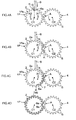
- FIG. 1 and FIGS. 2A to 2D sequentially illustrate a resin coating forming method for a spline shaft according to a first embodiment of the present invention.
- an adhesive 3 e.g. a primer
- FIGS. 2A to 2D sequentially illustrate the flow of a resin coating forming process.
- a toothed roller 4 is disposed at a side of the spline shaft 1, for example, to face the spline shaft 1.
- the toothed roller 4 has a center axis C2 that is parallel to a center axis C1 of the spline shaft 1 which has been heated by a heater (not illustrated).
- Teeth 5 of the toothed roller 4 are disposed with the same circumferential pitch as the circumferential pitch of the splines 2 of the spline shaft 1.
- a surface 5a of the teeth 5 of the toothed roller 4 is coated with a release layer 10.
- the release layer 10 is formed by coating the surface 5a with a known release agent such as a silicone resin, for example.
- the spline shaft 1 and the toothed roller 4 are rotated in conjunction with each other.
- the toothed roller 4 may be driven to be rotated about the center axis C2
- the spline shaft 1 may be rotated about the center axis C1 in accordance with the rotation of the toothed roller 4.
- both the spline shaft 1 and the toothed roller 4 may be driven to be rotated synchronously.
- one end 6a of a resin film 6 is supplied to a meshing portion A between the spline shaft 1 and the toothed roller 4 on the outer periphery 1a of the spline shaft 1 which is rotating.
- the one end 6a of the resin film 6 hung from above contacts a predetermined position in a region between the meshing portion A and a position B on the outer periphery 1a of the spline shaft 1.
- the position B is positioned a predetermined distance away from the meshing portion A in a direction X2 that is opposite to a rotational direction X1 of the spline shaft 1 (that is, positioned upstream of the meshing portion A in the rotational direction X1).
- the one end 6a of the resin film 6 is moved together with the outer periphery 1a of the spline shaft 1 from the state illustrated in FIG. 2A to the state illustrated in FIG. 2B to be fed to the meshing portion A along with the rotation of the spline shaft 1.
- the toothed roller 4 is disposed at a side of the spline shaft 1 as illustrated in FIG. 2A , for example, the position B is located above the center axis C1 on the outer periphery 1a of the spline shaft 1.
- the resin film 6 is made of a thermoplastic resin.
- the resin film 6 may be made of engineering plastic, for example.
- engineering plastic polyamide (PA) with high slidability is preferably used.
- PA 11, PA 12, PA 610, and PA 612 may be used.
- the resin film 6 may be made of at least one super engineering plastic selected from polyphenylene sulfide (PPS), polyether ether ketone (PEEK), polyarylate (PAR), polyethersulfone (PES), polyimide (PI), polyetherimide (PEI), fluorine resins, and other thermoplastic resins.
- the resin film 6 is wound up around the outer periphery 1a of the spline shaft 1 while the resin film 6 is pressed to be adhered to the surface 2a of the splines 2 at the meshing portion A along with interlocked rotation of the spline shaft 1 and the toothed roller 4.
- the surface 5a of the teeth 5 of the toothed roller 4 is coated with the release layer 10 (see FIG. 3 ). This suppresses adhesion of the resin film 6 to the toothed roller 4 side.
- a resin coating 7 is formed on the surface 2a of the splines 2 over the entire circumference of the spline shaft 1 with the one end 6a and the other end 6b of the resin film 6 located proximate to each other, just contacting each other, or overlapping each other by a minute amount.
- the resin film 6 is pressed by the toothed roller 4 to be uniformly spread while being heated at the meshing portion A to provide flowability.
- a resin coating with a uniform thickness and a high quality can be obtained.
- the width of the resin film 6 can be freely adjusted such that the resin film 6 does not lie off a portion to which the adhesive 3 has been applied. As a result, formation of the resin coating 7 on a portion to which the adhesive 3 has not been applied can be suppressed. Consequently, it is possible to suppress occurrence of a crack in the resin coating 7 due to a heat shock during use, which provides high durability.
- the one end 6a and the other end 6b of the resin film 6 are preferably adhered to a bottom land between the splines 2.
- the bottom land does not slide with the mating outer spline shaft when the spline shaft 1 (inner spline shaft) is combined with the mating outer spline shaft, and thus it does not matter at all whether or not the one end 6a and the other end 6a overlap each other at the bottom land.
- Use of super engineering plastic as the resin constituting the resin film 6 can provide the resin coating 7 with high wear resistance and high durability.
- the resin film 6 Since the resin film 6 is supplied to a position away from the meshing portion A in the direction X2, which is opposite to the rotational direction X1, on the outer periphery 1a of the spline shaft 1, the following advantage is obtained. That is, the resin film 6 is sufficiently heated to have high flowability before reaching the meshing portion A from the position on the outer periphery 1a of the spline shaft 1 at which the resin film 6 is supplied, and is caught in the meshing portion A. Thus, it is possible to reliably suppress fluctuations in thickness to provide a resin coating 7 with an even more uniform thickness.
- the surface 5a of the teeth 5 of the toothed roller 4 is coated with the release layer 10 (see FIG. 3 ). This allows the resin film 6 to reliably adhere to the spline shaft 1 without adhesion of the resin film 6 to the toothed roller 4 side.
- the spline shaft 1 on which a resin coating is formed using the resin coating forming method is suitably used as an intermediate shaft for vehicles interposed between a steering shaft and a steering gear.
- FIGS. 4A to 4D illustrate processes of a resin coating forming method according to a second embodiment of the present invention.
- This embodiment is different from the resin coating forming method according to the first embodiment in the following point.
- a toothless region K on which splines 2 are not provided is provided on a part of an outer periphery 1Pa of a spline shaft 1P, and one end 6a and the other end 6b of a resin film 6 are disposed in the toothless region K.
- Constituent elements of the second embodiment of FIGS. 4A to 4D that are the same as those of the first embodiment of FIGS. 2A to 2D are given the same reference numerals as those given to the constituent elements of the first embodiment of FIGS. 2A to 2D .
- the one end 6a of the resin film 6 is supplied so as to contact the toothless region K on the outer periphery 1Pa of the spline shaft 1P.
- the other end 6b of the resin film 6 is adhered to the toothless region K in the state illustrated in FIG. 4D (a state in which the toothless region K reaches the meshing portion A again) in which the spline shaft 1P has made generally one rotation from the state illustrated in FIG. 4B in which the one end 6a of the resin film 6 in the toothless region K is caught in the meshing portion A.
- the same effect as the effect of the first embodiment can be achieved.
- the function of the spline shaft 1P is not affected at all irrespective of whether or not the one end 6a and the other end 6b of the resin film 6 wound up by the spline shaft 1P overlap each other in the toothless region K.
- the toothless region K can be caused to function as a grease pool when the spline shaft 1P (inner spline shaft) is combined with the mating outer spline shaft.
- FIG. 5 illustrates a third embodiment as a modification of the second embodiment.
- a single toothless region K is provided in the second embodiment of FIGS. 4A to 4D .
- a first toothless region K1 and a second toothless region K2 are disposed away from each other in the circumferential direction on an outer periphery 1Qa of a spline shaft 1Q, and a first resin film 8 and a second resin film 9 are used.
- the two toothless regions K1 and K2 may be disposed at positions that are opposite to each other in the radial direction, for example.
- One end 8a of the first resin film 8 and the other end 9b of the second resin film 9 are disposed in the first toothless region K1.
- the other end 8b of the first resin film 8 and one end 9a of the second resin film 9 are disposed in the second toothless region K2.
- the same material as the material of the resin film 6 according to the first embodiment is used as the material of the resin films 8 and 9.
- Constituent elements of the third embodiment of FIG. 5 that are the same as those of the second embodiment of FIG. 2D are given the same reference numerals as those given to the constituent elements of the second embodiment of FIG. 2D .
- the same effect as the effect of the first embodiment can be achieved.
- the function of the spline shaft 1Q is not affected at all irrespective of whether or not the corresponding end portions of the resin films 8 and 9 overlap each other in the toothless regions K1 and K2.
- the toothless regions K1 and K2 can be caused to function as grease pools when the spline shaft 1Q (inner spline shaft) is combined with the corresponding outer spline shaft.
- Three or more toothless regions may be provided, and a corresponding number of resin films may also be used.
- the surface of the teeth 5 of the toothed roller 4 is coated with the release layer 10 (see FIG. 3 ).
- the resin film 6 and a release film 11 which is disposed nearer to a toothed roller 4R than the resin film 6 may be caught in the meshing portion A in an overlapping manner as in a fourth embodiment illustrated in FIG. 6 .
- a known release film may be used as the release film 11.
- a resin film with high release properties such as polypropylene (PP), PE (polyethylene), or PET (polyethylene terephthalate) or such a resin film coated with a release resin such as a silicone resin may be used as the release film 11.
- the release film 11 is interposed between the resin film 6 and the toothed roller 4R at the meshing portion A.
- the resin film 6 can be reliably caused to adhere to the spline shaft 1.
Landscapes
- Engineering & Computer Science (AREA)
- General Engineering & Computer Science (AREA)
- Mechanical Engineering (AREA)
- Physics & Mathematics (AREA)
- Fluid Mechanics (AREA)
- Ocean & Marine Engineering (AREA)
- Shafts, Cranks, Connecting Bars, And Related Bearings (AREA)
- Coating Apparatus (AREA)
- Application Of Or Painting With Fluid Materials (AREA)
- Rolls And Other Rotary Bodies (AREA)
Abstract
Description
- The present invention relates to a resin coating forming method for a spline shaft, and to a spline shaft.
- Hitherto, a fluidized-bed coating method has been commonly used as a method of forming a resin coating on the surface of splines on the outer periphery of a spline shaft (see Japanese Patent Application Publication No.
2012-197838 JP 2012-197838 A - In the fluidized-bed coating process, an amount of resin powder that is enough to apply the resin powder to the bottom land of the splines, and therefore a thick resin layer is formed. Thus, in order to reduce the final thickness of the resin coating, the surface of the resin layer is broached (broaching process).
- However, voids (air bubbles) may be formed at the boundary between the resin layer and the surface of the splines during the cooling after the fluidized-bed coating, and the resin layer may be peeled off during the broaching, which increases the rate of defectives caused during the manufacture. This increases the cost of manufacture. In addition, since a part of the resin layer is broached during the broaching, a large material loss is caused, which also increases the cost of manufacture. In the case where a part of the resin coating is applied to a portion of the spline shaft to which no primer has adhered, meanwhile, the resin coating may be cracked, starting from the above-mentioned part, by a stress load (so-called heat shock) due to variations in temperature during use, which degrades durability.
- In addition, it is difficult to perform the broaching process with good positioning with respect to the splines. Therefore, it is difficult to make the final thickness of the resin coating uniform, which degrades quality.
- An object of the present invention is to provide a resin coating forming method for a spline shaft and a spline shaft that provide a resin coating with high quality and high durability at a low cost.
- An aspect of the present invention provides a resin coating forming method for a spline shaft, including: causing a resin film to be caught in a meshing portion between a spline shaft and a toothed roller, the spline shaft having an adhesive applied to a surface of splines formed on an outer periphery of the spline shaft and having been heated, and the toothed roller being rotatable about a center axis that is parallel to a center axis of the spline shaft; and winding up the resin film around the outer periphery of the spline shaft while the resin film is pressed to be adhered to the surface of the splines by the toothed roller at the meshing portion along with interlocked rotation of the spline shaft and the toothed roller to form a resin coating on the surface of the splines.
- The foregoing and further features and advantages of the invention will become apparent from the following description of example embodiments with reference to the accompanying drawings, wherein like numerals are used to represent like elements and wherein:
-
FIG. 1 is a schematic view illustrating an adhesive application process in a resin coating forming method for a spline shaft according to a first embodiment of the present invention; -
FIGS. 2A to 2D sequentially illustrate the flow of a resin coating forming process according to the first embodiment; -
FIG. 3 is a schematic view of an essential portion of a toothed roller according to the first embodiment; -
FIGS. 4A to 4D sequentially illustrate the flow of a resin coating forming process of a resin coating forming method for a spline shaft according to a second embodiment of the present invention; -
FIG. 5 is a schematic view illustrating a final stage of a resin coating forming process of a resin coating forming method for a spline shaft according to a third embodiment of the present invention; and -
FIG. 6 is a schematic view illustrating an intermediate stage of a resin coating forming process of a resin coating forming method for a spline shaft according to a fourth embodiment of the present invention. - Preferred embodiments of the present invention will be described with reference to the drawings.
-
FIG. 1 andFIGS. 2A to 2D sequentially illustrate a resin coating forming method for a spline shaft according to a first embodiment of the present invention. In an adhesive application process illustrated inFIG. 1 , first, an adhesive 3, e.g. a primer, is applied to asurface 2a ofsplines 2 formed on anouter periphery 1a of aspline shaft 1. -
FIGS. 2A to 2D sequentially illustrate the flow of a resin coating forming process. - As illustrated in
FIG. 2A , atoothed roller 4 is disposed at a side of thespline shaft 1, for example, to face thespline shaft 1. Thetoothed roller 4 has a center axis C2 that is parallel to a center axis C1 of thespline shaft 1 which has been heated by a heater (not illustrated).Teeth 5 of thetoothed roller 4 are disposed with the same circumferential pitch as the circumferential pitch of thesplines 2 of thespline shaft 1. As illustrated inFIG. 3 , asurface 5a of theteeth 5 of thetoothed roller 4 is coated with arelease layer 10. Therelease layer 10 is formed by coating thesurface 5a with a known release agent such as a silicone resin, for example. - As illustrated in
FIGS. 2A to 2C , thespline shaft 1 and thetoothed roller 4 are rotated in conjunction with each other. For example, thetoothed roller 4 may be driven to be rotated about the center axis C2, and thespline shaft 1 may be rotated about the center axis C1 in accordance with the rotation of thetoothed roller 4. Alternatively, both thespline shaft 1 and thetoothed roller 4 may be driven to be rotated synchronously. - As illustrated in
FIG. 2A , oneend 6a of aresin film 6 is supplied to a meshing portion A between thespline shaft 1 and thetoothed roller 4 on theouter periphery 1a of thespline shaft 1 which is rotating. Specifically, as illustrated inFIG. 2A , the oneend 6a of theresin film 6 hung from above contacts a predetermined position in a region between the meshing portion A and a position B on theouter periphery 1a of thespline shaft 1. The position B is positioned a predetermined distance away from the meshing portion A in a direction X2 that is opposite to a rotational direction X1 of the spline shaft 1 (that is, positioned upstream of the meshing portion A in the rotational direction X1). - Consequently, the one
end 6a of theresin film 6 is moved together with theouter periphery 1a of thespline shaft 1 from the state illustrated inFIG. 2A to the state illustrated inFIG. 2B to be fed to the meshing portion A along with the rotation of thespline shaft 1. In the case where thetoothed roller 4 is disposed at a side of thespline shaft 1 as illustrated inFIG. 2A , for example, the position B is located above the center axis C1 on theouter periphery 1a of thespline shaft 1. - The
resin film 6 is made of a thermoplastic resin. Theresin film 6 may be made of engineering plastic, for example. As the engineering plastic, polyamide (PA) with high slidability is preferably used. Specifically, PA 11, PA 12, PA 610, and PA 612 may be used. Alternatively, theresin film 6 may be made of at least one super engineering plastic selected from polyphenylene sulfide (PPS), polyether ether ketone (PEEK), polyarylate (PAR), polyethersulfone (PES), polyimide (PI), polyetherimide (PEI), fluorine resins, and other thermoplastic resins. - As illustrated in
FIGS. 2B and 2C , theresin film 6 is wound up around theouter periphery 1a of thespline shaft 1 while theresin film 6 is pressed to be adhered to thesurface 2a of thesplines 2 at the meshing portion A along with interlocked rotation of thespline shaft 1 and thetoothed roller 4. In this event, thesurface 5a of theteeth 5 of thetoothed roller 4 is coated with the release layer 10 (seeFIG. 3 ). This suppresses adhesion of theresin film 6 to thetoothed roller 4 side. - When the
spline shaft 1 makes generally one rotation from the state illustrated inFIG. 2B in which the oneend 6a of theresin film 6 is caught in the meshing portion A, aresin coating 7 is formed on thesurface 2a of thesplines 2 over the entire circumference of thespline shaft 1 with the oneend 6a and theother end 6b of theresin film 6 located proximate to each other, just contacting each other, or overlapping each other by a minute amount. - In this embodiment, the
resin film 6 is pressed by thetoothed roller 4 to be uniformly spread while being heated at the meshing portion A to provide flowability. Thus, a resin coating with a uniform thickness and a high quality can be obtained. - In addition, a cutting process such as the broaching in the related art is not required, which does not cause a crack during processing or a material loss. The
resin film 6 which is sequentially fed to the meshing portion A is pressed to thesplines 2 side by thetoothed roller 4. This suppresses occurrence of a shaping failure with air bubbles remaining on the back side of theresin film 6. Thus, the cost of manufacture can be reduced. - The width of the
resin film 6 can be freely adjusted such that theresin film 6 does not lie off a portion to which the adhesive 3 has been applied. As a result, formation of theresin coating 7 on a portion to which the adhesive 3 has not been applied can be suppressed. Consequently, it is possible to suppress occurrence of a crack in theresin coating 7 due to a heat shock during use, which provides high durability. The oneend 6a and theother end 6b of theresin film 6 are preferably adhered to a bottom land between thesplines 2. This is because the bottom land does not slide with the mating outer spline shaft when the spline shaft 1 (inner spline shaft) is combined with the mating outer spline shaft, and thus it does not matter at all whether or not the oneend 6a and theother end 6a overlap each other at the bottom land. - Use of super engineering plastic as the resin constituting the
resin film 6 can provide theresin coating 7 with high wear resistance and high durability. - Since the
resin film 6 is supplied to a position away from the meshing portion A in the direction X2, which is opposite to the rotational direction X1, on theouter periphery 1a of thespline shaft 1, the following advantage is obtained. That is, theresin film 6 is sufficiently heated to have high flowability before reaching the meshing portion A from the position on theouter periphery 1a of thespline shaft 1 at which theresin film 6 is supplied, and is caught in the meshing portion A. Thus, it is possible to reliably suppress fluctuations in thickness to provide aresin coating 7 with an even more uniform thickness. - The
surface 5a of theteeth 5 of thetoothed roller 4 is coated with the release layer 10 (seeFIG. 3 ). This allows theresin film 6 to reliably adhere to thespline shaft 1 without adhesion of theresin film 6 to thetoothed roller 4 side. Thespline shaft 1 on which a resin coating is formed using the resin coating forming method is suitably used as an intermediate shaft for vehicles interposed between a steering shaft and a steering gear. -
FIGS. 4A to 4D illustrate processes of a resin coating forming method according to a second embodiment of the present invention. - This embodiment is different from the resin coating forming method according to the first embodiment in the following point. A toothless region K on which splines 2 are not provided is provided on a part of an outer periphery 1Pa of a
spline shaft 1P, and oneend 6a and theother end 6b of aresin film 6 are disposed in the toothless region K. Constituent elements of the second embodiment ofFIGS. 4A to 4D that are the same as those of the first embodiment ofFIGS. 2A to 2D are given the same reference numerals as those given to the constituent elements of the first embodiment ofFIGS. 2A to 2D . - As illustrated in
FIG. 4A , the oneend 6a of theresin film 6 is supplied so as to contact the toothless region K on the outer periphery 1Pa of thespline shaft 1P. Theother end 6b of theresin film 6 is adhered to the toothless region K in the state illustrated inFIG. 4D (a state in which the toothless region K reaches the meshing portion A again) in which thespline shaft 1P has made generally one rotation from the state illustrated inFIG. 4B in which the oneend 6a of theresin film 6 in the toothless region K is caught in the meshing portion A. - According to this embodiment, the same effect as the effect of the first embodiment can be achieved. Further, the function of the
spline shaft 1P is not affected at all irrespective of whether or not the oneend 6a and theother end 6b of theresin film 6 wound up by thespline shaft 1P overlap each other in the toothless region K. In addition, the toothless region K can be caused to function as a grease pool when thespline shaft 1P (inner spline shaft) is combined with the mating outer spline shaft. -
FIG. 5 illustrates a third embodiment as a modification of the second embodiment. In the second embodiment ofFIGS. 4A to 4D , a single toothless region K is provided. In the third embodiment illustrated inFIG. 5 [corresponding to the state ofFIG. 2D at the time when the coating forming process is finished], in contrast, a first toothless region K1 and a second toothless region K2 are disposed away from each other in the circumferential direction on an outer periphery 1Qa of aspline shaft 1Q, and afirst resin film 8 and asecond resin film 9 are used. The two toothless regions K1 and K2 may be disposed at positions that are opposite to each other in the radial direction, for example. - One
end 8a of thefirst resin film 8 and theother end 9b of thesecond resin film 9 are disposed in the first toothless region K1. Theother end 8b of thefirst resin film 8 and oneend 9a of thesecond resin film 9 are disposed in the second toothless region K2. The same material as the material of theresin film 6 according to the first embodiment is used as the material of theresin films FIG. 5 that are the same as those of the second embodiment ofFIG. 2D are given the same reference numerals as those given to the constituent elements of the second embodiment ofFIG. 2D . - According to the third embodiment, the same effect as the effect of the first embodiment can be achieved. Further, the function of the
spline shaft 1Q is not affected at all irrespective of whether or not the corresponding end portions of theresin films spline shaft 1Q (inner spline shaft) is combined with the corresponding outer spline shaft. - Three or more toothless regions may be provided, and a corresponding number of resin films may also be used.
- In the first to third embodiments, the surface of the
teeth 5 of thetoothed roller 4 is coated with the release layer 10 (seeFIG. 3 ). Instead, theresin film 6 and arelease film 11 which is disposed nearer to atoothed roller 4R than theresin film 6 may be caught in the meshing portion A in an overlapping manner as in a fourth embodiment illustrated inFIG. 6 . A known release film may be used as therelease film 11. For example, a resin film with high release properties such as polypropylene (PP), PE (polyethylene), or PET (polyethylene terephthalate) or such a resin film coated with a release resin such as a silicone resin may be used as therelease film 11. - In the fourth embodiment, the
release film 11 is interposed between theresin film 6 and thetoothed roller 4R at the meshing portion A. Thus, theresin film 6 can be reliably caused to adhere to thespline shaft 1. - The present invention is not limited to the embodiments described above, and may be modified in various ways without departing from the scope and spirits of the present invention.
Claims (7)
- A resin coating forming method for a spline shaft, comprising:causing a resin film to be caught in a meshing portion between a spline shaft and a toothed roller, the spline shaft having an adhesive applied to a surface of splines formed on an outer periphery of the spline shaft and having been heated, and the toothed roller being rotatable about a center axis that is parallel to a center axis of the spline shaft; andwinding up the resin film around the outer periphery of the spline shaft while the resin film is pressed to be adhered to the surface of the splines by the toothed roller at the meshing portion along with interlocked rotation of the spline shaft and the toothed roller to form a resin coating on the surface of the splines.
- The resin coating forming method for a spline shaft according to claim 1, wherein the spline shaft includes a toothless region to which one end or the other end of the resin film is attached.
- The resin coating forming method for a spline shaft according to claim 1 or 2, wherein
the resin film is made of at least one super engineering plastic selected from polyphenylene sulfide (PPS), polyether ether ketone (PEEK), polyarylate (PAR), polyethersulfone (PES), polyimide (PI), polyetherimide (PEI), fluorine resins, and other thermoplastic resins. - The resin coating forming method for a spline shaft according to any one of claims 1 to 3, wherein
a surface of teeth of the toothed roller is coated with a release layer. - The resin coating forming method for a spline shaft according to any one of claims 1 to 3, wherein
the resin film and a release film disposed nearer to a toothed roller than the resin film are caught in the meshing portion in an overlapping manner. - The resin coating forming method for a spline shaft according to any one of claims 1 to 5, wherein
the resin film is supplied to a position on the outer periphery of the spline shaft away from the meshing portion in a direction that is opposite to a rotational direction. - A spline shaft comprising:a resin coating formed on a surface of splines using the resin coating forming method for a spline shaft according to any one of claims 1 to 6.
Applications Claiming Priority (1)
| Application Number | Priority Date | Filing Date | Title |
|---|---|---|---|
| JP2014045145A JP2015169285A (en) | 2014-03-07 | 2014-03-07 | Resin coating forming method of spline shaft and spline shaft |
Publications (2)
| Publication Number | Publication Date |
|---|---|
| EP2916020A2 true EP2916020A2 (en) | 2015-09-09 |
| EP2916020A3 EP2916020A3 (en) | 2016-06-22 |
Family
ID=52705962
Family Applications (1)
| Application Number | Title | Priority Date | Filing Date |
|---|---|---|---|
| EP15157525.5A Withdrawn EP2916020A3 (en) | 2014-03-07 | 2015-03-04 | Resin coating forming method for spline shaft and spline shaft |
Country Status (4)
| Country | Link |
|---|---|
| US (1) | US20150251399A1 (en) |
| EP (1) | EP2916020A3 (en) |
| JP (1) | JP2015169285A (en) |
| CN (1) | CN104890229A (en) |
Families Citing this family (2)
| Publication number | Priority date | Publication date | Assignee | Title |
|---|---|---|---|---|
| DE102016114970A1 (en) * | 2016-08-11 | 2018-02-15 | Thyssenkrupp Ag | Steering shaft for a motor vehicle |
| CN113881080B (en) * | 2021-10-12 | 2023-05-30 | 上海工程技术大学 | High-heat-conductivity low-dielectric film based on sandwich structure and preparation method thereof |
Citations (1)
| Publication number | Priority date | Publication date | Assignee | Title |
|---|---|---|---|---|
| JP2012197838A (en) | 2011-03-18 | 2012-10-18 | Jtekt Corp | Manufacturing method for power transmission shaft and vehicle steering device |
Family Cites Families (7)
| Publication number | Priority date | Publication date | Assignee | Title |
|---|---|---|---|---|
| JPS63176824A (en) * | 1987-01-12 | 1988-07-21 | Toyota Motor Corp | Slide spline and manufacture thereof |
| JPH0341221A (en) * | 1990-06-22 | 1991-02-21 | Toyota Motor Corp | Production of resin-coated spline shaft |
| JP3631084B2 (en) * | 1999-09-13 | 2005-03-23 | 光洋精工株式会社 | Coated product, method for producing the same, and coating apparatus |
| JP2003011280A (en) * | 2001-07-04 | 2003-01-15 | Koyo Seiko Co Ltd | Connecting member having fitting part |
| JP2004324875A (en) * | 2003-04-11 | 2004-11-18 | Shin Kobe Electric Mach Co Ltd | Manufacturing method of resin or metal gears |
| JP2011038560A (en) * | 2009-08-07 | 2011-02-24 | Jtekt Corp | Spline telescopic shaft, method of manufacturing the same, and vehicle steering apparatus |
| JP2011174498A (en) * | 2010-02-23 | 2011-09-08 | Jtekt Corp | Spline telescopic shaft, vehicle steering gear provided with spline telescopic shaft, and method for manufacturing spline telescopic shaft |
-
2014
- 2014-03-07 JP JP2014045145A patent/JP2015169285A/en active Pending
-
2015
- 2015-02-27 US US14/633,882 patent/US20150251399A1/en not_active Abandoned
- 2015-03-04 EP EP15157525.5A patent/EP2916020A3/en not_active Withdrawn
- 2015-03-05 CN CN201510098263.5A patent/CN104890229A/en active Pending
Patent Citations (1)
| Publication number | Priority date | Publication date | Assignee | Title |
|---|---|---|---|---|
| JP2012197838A (en) | 2011-03-18 | 2012-10-18 | Jtekt Corp | Manufacturing method for power transmission shaft and vehicle steering device |
Also Published As
| Publication number | Publication date |
|---|---|
| CN104890229A (en) | 2015-09-09 |
| EP2916020A3 (en) | 2016-06-22 |
| US20150251399A1 (en) | 2015-09-10 |
| JP2015169285A (en) | 2015-09-28 |
Similar Documents
| Publication | Publication Date | Title |
|---|---|---|
| ES2865277T3 (en) | Bearing with shoulder segments | |
| EP3020992A3 (en) | Method of manufacturing torque transmission shaft and vehicle steering apparatus | |
| US20220055145A1 (en) | Friction stir welding method | |
| US20150251399A1 (en) | Resin coating forming method for spline shaft and spline shaft | |
| US20160250788A1 (en) | Method for manufacturing sealing device | |
| WO2016023043A1 (en) | Non-woven, fracture reducing brake rotor preforms and pads | |
| TW201615296A (en) | Roller with composite angle flange | |
| US8499925B2 (en) | Conveying roller and method of making the same | |
| US9752333B2 (en) | Trowel | |
| US20240084881A1 (en) | System, method and apparatus for metallic gear hub with metallic teeth having outer polymer layer | |
| US9126355B2 (en) | Composite material part manufacturing process using removable and retainable material | |
| EP3263448A3 (en) | Manufacturing method of polymer composite/metal load transfer joint for landing gear | |
| US20170232649A1 (en) | Flush field joint | |
| EP3795342A1 (en) | Spur gear component, spur gear, and manufacturing method of spur gear component | |
| US20180313398A1 (en) | Multi-component driveshaft | |
| US1755387A (en) | Shaft protector and method of manufacturing the same | |
| US20190193140A1 (en) | Multi-material construction of gears | |
| JP6312491B2 (en) | Web manufacturing roll | |
| JP5529490B2 (en) | Endless belt | |
| TW201637029A (en) | Electric insulated wire and manufacturing method therefore | |
| JP2011033064A (en) | Tapered roller bearing | |
| JP6981245B2 (en) | Resin gears | |
| RU2599938C2 (en) | Permanent part connection method | |
| JP6435802B2 (en) | roller | |
| CN105936126B (en) | The manufacturing method of tubular body cladding parts |
Legal Events
| Date | Code | Title | Description |
|---|---|---|---|
| PUAI | Public reference made under article 153(3) epc to a published international application that has entered the european phase |
Free format text: ORIGINAL CODE: 0009012 |
|
| AK | Designated contracting states |
Kind code of ref document: A2 Designated state(s): AL AT BE BG CH CY CZ DE DK EE ES FI FR GB GR HR HU IE IS IT LI LT LU LV MC MK MT NL NO PL PT RO RS SE SI SK SM TR |
|
| AX | Request for extension of the european patent |
Extension state: BA ME |
|
| PUAL | Search report despatched |
Free format text: ORIGINAL CODE: 0009013 |
|
| AK | Designated contracting states |
Kind code of ref document: A3 Designated state(s): AL AT BE BG CH CY CZ DE DK EE ES FI FR GB GR HR HU IE IS IT LI LT LU LV MC MK MT NL NO PL PT RO RS SE SI SK SM TR |
|
| AX | Request for extension of the european patent |
Extension state: BA ME |
|
| RIC1 | Information provided on ipc code assigned before grant |
Ipc: F16D 3/06 20060101AFI20160519BHEP Ipc: F16D 1/10 20060101ALN20160519BHEP |
|
| STAA | Information on the status of an ep patent application or granted ep patent |
Free format text: STATUS: THE APPLICATION IS DEEMED TO BE WITHDRAWN |
|
| 18D | Application deemed to be withdrawn |
Effective date: 20161223 |