EP2915974A1 - Turbocharger and diesel engine comprising the same - Google Patents
Turbocharger and diesel engine comprising the same Download PDFInfo
- Publication number
- EP2915974A1 EP2915974A1 EP14200071.0A EP14200071A EP2915974A1 EP 2915974 A1 EP2915974 A1 EP 2915974A1 EP 14200071 A EP14200071 A EP 14200071A EP 2915974 A1 EP2915974 A1 EP 2915974A1
- Authority
- EP
- European Patent Office
- Prior art keywords
- inlet
- mixing part
- air
- side wall
- exhaust gas
- Prior art date
- Legal status (The legal status is an assumption and is not a legal conclusion. Google has not performed a legal analysis and makes no representation as to the accuracy of the status listed.)
- Withdrawn
Links
Images



Classifications
-
- F—MECHANICAL ENGINEERING; LIGHTING; HEATING; WEAPONS; BLASTING
- F02—COMBUSTION ENGINES; HOT-GAS OR COMBUSTION-PRODUCT ENGINE PLANTS
- F02B—INTERNAL-COMBUSTION PISTON ENGINES; COMBUSTION ENGINES IN GENERAL
- F02B37/00—Engines characterised by provision of pumps driven at least for part of the time by exhaust
-
- F—MECHANICAL ENGINEERING; LIGHTING; HEATING; WEAPONS; BLASTING
- F02—COMBUSTION ENGINES; HOT-GAS OR COMBUSTION-PRODUCT ENGINE PLANTS
- F02B—INTERNAL-COMBUSTION PISTON ENGINES; COMBUSTION ENGINES IN GENERAL
- F02B39/00—Component parts, details, or accessories relating to, driven charging or scavenging pumps, not provided for in groups F02B33/00 - F02B37/00
-
- F—MECHANICAL ENGINEERING; LIGHTING; HEATING; WEAPONS; BLASTING
- F02—COMBUSTION ENGINES; HOT-GAS OR COMBUSTION-PRODUCT ENGINE PLANTS
- F02M—SUPPLYING COMBUSTION ENGINES IN GENERAL WITH COMBUSTIBLE MIXTURES OR CONSTITUENTS THEREOF
- F02M26/00—Engine-pertinent apparatus for adding exhaust gases to combustion-air, main fuel or fuel-air mixture, e.g. by exhaust gas recirculation [EGR] systems
-
- F—MECHANICAL ENGINEERING; LIGHTING; HEATING; WEAPONS; BLASTING
- F02—COMBUSTION ENGINES; HOT-GAS OR COMBUSTION-PRODUCT ENGINE PLANTS
- F02M—SUPPLYING COMBUSTION ENGINES IN GENERAL WITH COMBUSTIBLE MIXTURES OR CONSTITUENTS THEREOF
- F02M26/00—Engine-pertinent apparatus for adding exhaust gases to combustion-air, main fuel or fuel-air mixture, e.g. by exhaust gas recirculation [EGR] systems
- F02M26/02—EGR systems specially adapted for supercharged engines
- F02M26/04—EGR systems specially adapted for supercharged engines with a single turbocharger
- F02M26/06—Low pressure loops, i.e. wherein recirculated exhaust gas is taken out from the exhaust downstream of the turbocharger turbine and reintroduced into the intake system upstream of the compressor
-
- F—MECHANICAL ENGINEERING; LIGHTING; HEATING; WEAPONS; BLASTING
- F02—COMBUSTION ENGINES; HOT-GAS OR COMBUSTION-PRODUCT ENGINE PLANTS
- F02M—SUPPLYING COMBUSTION ENGINES IN GENERAL WITH COMBUSTIBLE MIXTURES OR CONSTITUENTS THEREOF
- F02M26/00—Engine-pertinent apparatus for adding exhaust gases to combustion-air, main fuel or fuel-air mixture, e.g. by exhaust gas recirculation [EGR] systems
- F02M26/02—EGR systems specially adapted for supercharged engines
- F02M26/09—Constructional details, e.g. structural combinations of EGR systems and supercharger systems; Arrangement of the EGR and supercharger systems with respect to the engine
-
- F—MECHANICAL ENGINEERING; LIGHTING; HEATING; WEAPONS; BLASTING
- F02—COMBUSTION ENGINES; HOT-GAS OR COMBUSTION-PRODUCT ENGINE PLANTS
- F02M—SUPPLYING COMBUSTION ENGINES IN GENERAL WITH COMBUSTIBLE MIXTURES OR CONSTITUENTS THEREOF
- F02M26/00—Engine-pertinent apparatus for adding exhaust gases to combustion-air, main fuel or fuel-air mixture, e.g. by exhaust gas recirculation [EGR] systems
- F02M26/13—Arrangement or layout of EGR passages, e.g. in relation to specific engine parts or for incorporation of accessories
- F02M26/17—Arrangement or layout of EGR passages, e.g. in relation to specific engine parts or for incorporation of accessories in relation to the intake system
- F02M26/19—Means for improving the mixing of air and recirculated exhaust gases, e.g. venturis or multiple openings to the intake system
-
- F—MECHANICAL ENGINEERING; LIGHTING; HEATING; WEAPONS; BLASTING
- F02—COMBUSTION ENGINES; HOT-GAS OR COMBUSTION-PRODUCT ENGINE PLANTS
- F02M—SUPPLYING COMBUSTION ENGINES IN GENERAL WITH COMBUSTIBLE MIXTURES OR CONSTITUENTS THEREOF
- F02M35/00—Combustion-air cleaners, air intakes, intake silencers, or induction systems specially adapted for, or arranged on, internal-combustion engines
- F02M35/12—Intake silencers ; Sound modulation, transmission or amplification
- F02M35/1205—Flow throttling or guiding
- F02M35/1216—Flow throttling or guiding by using a plurality of holes, slits, protrusions, perforations, ribs or the like; Surface structures; Turbulence generators
-
- F—MECHANICAL ENGINEERING; LIGHTING; HEATING; WEAPONS; BLASTING
- F02—COMBUSTION ENGINES; HOT-GAS OR COMBUSTION-PRODUCT ENGINE PLANTS
- F02M—SUPPLYING COMBUSTION ENGINES IN GENERAL WITH COMBUSTIBLE MIXTURES OR CONSTITUENTS THEREOF
- F02M35/00—Combustion-air cleaners, air intakes, intake silencers, or induction systems specially adapted for, or arranged on, internal-combustion engines
- F02M35/12—Intake silencers ; Sound modulation, transmission or amplification
- F02M35/1288—Intake silencers ; Sound modulation, transmission or amplification combined with or integrated into other devices ; Plurality of air intake silencers
-
- Y—GENERAL TAGGING OF NEW TECHNOLOGICAL DEVELOPMENTS; GENERAL TAGGING OF CROSS-SECTIONAL TECHNOLOGIES SPANNING OVER SEVERAL SECTIONS OF THE IPC; TECHNICAL SUBJECTS COVERED BY FORMER USPC CROSS-REFERENCE ART COLLECTIONS [XRACs] AND DIGESTS
- Y02—TECHNOLOGIES OR APPLICATIONS FOR MITIGATION OR ADAPTATION AGAINST CLIMATE CHANGE
- Y02T—CLIMATE CHANGE MITIGATION TECHNOLOGIES RELATED TO TRANSPORTATION
- Y02T10/00—Road transport of goods or passengers
- Y02T10/10—Internal combustion engine [ICE] based vehicles
- Y02T10/12—Improving ICE efficiencies
Definitions
- the present invention relates to a turbocharger and a diesel engine comprising the same and particularly relates to a turbocharger which recirculates exhaust gas from a vessel diesel engine, a diesel engine for land-based power generation, or similar diesel engine.
- exhaust gas of a diesel engine contains harmful substances and substances that have an effect on environment such as NOx, SOx, ash dust, and the like.
- An exemplary method of reducing harmful substances is exhaust gas recirculation (EGR), a method by which NOx can be reduced (e.g. see Patent Document 1).
- combustion temperature can be lowered and NOx formation can be prevented by mixing a portion of the exhaust gas with combustion air and combusting.
- Air that has been mixed with exhaust gas has a lower concentration of oxygen than atmospheric air. Therefore, the combustion rate or, in other words, the reaction between the fuel and oxygen can be slowed.
- carbon dioxide and water vapor that is abundant in the exhaust gas has a specific heat capacity that is greater than that of air. Therefore, temperature increases can be kept small for equivalent caloric value. Due to these effects, the maximum temperature of the flame can be reduced and, therefore, NOx production (Thermal NOx) can be suppressed.
- Patent Document 1 describes an inlet channel, which is connected to a small turbocharger mounted on a diesel engine of a vehicle, which recirculates exhaust gas.
- Patent Document 1 Japanese Unexamined Patent Application Publication (Translation of PCT Application) No. 2009-511797
- a turbocharger 100 has a structure by which external air (fresh air) inhaled through a silencer 101 is guided to an intake port 103 located before a compressor 102. Additionally, said structure does not include an intake pipe. As a result, with large turbochargers, as recited in the invention described in Patent Document 1, there is a problem in that exhaust gas cannot be circulated to the intake pipe.
- drift is generated due to the distance between the intake port 103 and the compressor 102 being short, and deviations in the temperature of the mixed air constituted by the inhaled air and the exhaust gas are generated.
- an object of the present invention is to provide a turbocharger by which deviations in the temperature of mixed air constituted by recirculated exhaust gas and inhaled air can be prevented, thus enabling the suppression of declines in efficiency and declines in reliability; and to provide a diesel engine comprising this turbocharger.
- a turbocharger and a diesel engine comprising the same of the present invention employ the following means to solve the problems described above.
- a turbocharger comprises: a turbine rotated by exhaust gas exhausted from a diesel engine, a rotating shaft having the turbine provided on a one end thereof, a compressor provided on another end of the rotating shaft, which compresses air inhaled through an intake port as a result of the rotation of the turbine, and mixing means provided upstream of the intake port.
- the mixing means mix the air and a portion of the exhaust gas and guide the mixture to the intake port.
- Exhaust gas recirculation (EGR) systems in which a portion of exhaust gas exhausted from a diesel engine is recirculated to an inlet channel connected to a turbocharger in order to reduce combustion temperature, are in practical use in small turbochargers mounted on diesel engines of motor vehicles and the like.
- EGR exhaust gas recirculation
- the intake port is provided in before the compressor and an inlet channel is not provided.
- drift is generated due to the distance between the intake port and the compressor being short, and deviations in temperature are generated due to a mixture of the inhaled air and the exhaust gas being uneven.
- mixing means for mixing the air inhaled by the compressor and the portion of the exhaust gas exhausted by the diesel engine are provided upstream of the intake port of the compressor.
- the air and the exhaust gas can be mixed uniformly and guided to the compressor. Therefore, drift caused by the air guided to the compressor and the exhaust gas can be prevented, the air and the exhaust gas can be uniformly mixed, and air (mixed air) having a uniform temperature can be guided to the intake port. Thus, declines in the efficiency and declines in reliability of the turbocharger can be suppressed.
- the mixing means may have a configuration comprising a substantially cylindrical mixing part therein, which has a plurality of holes in a side wall thereof; and an inlet by which the portion of the exhaust gas is introduced.
- a one end in the axial direction of the mixing part is connected to the intake port, and the air is inhaled into another end of the mixing part.
- the one end in the axial direction of the mixing part is connected to the intake port and air is inhaled from another end.
- the exhaust gas guided into of the mixing means from the inlet can be guided into the mixing part from the holes provided in the side wall of the mixing part, and the air and the exhaust gas can be mixed within the mixing part.
- uniformly blended mixed air can be passed through the mixing part and supplied to the intake port.
- the number of the holes provided in the side wall of the mixing part facing the inlet may be less than the number of the holes provided in the side wall not facing the inlet.
- the number of holes provided in the side wall of the mixing part facing the inlet is configured to be less than the number of holes provided in the side wall not facing the inlet.
- the diameter of the holes provided in the side wall of the mixing part facing the inlet may be smaller than the diameter of the holes provided in the side wall not facing the inlet.
- the diameter of the holes provided in the side wall of the mixing part facing the inlet is configured to be smaller than the diameter of the holes provided in the side wall not facing the inlet.
- a hole area of the holes provided in the side wall of the mixing part facing the inlet may be from 0.3 times to 0.8 times a hole area of the holes provided in the side wall not facing the inlet.
- the hole area of the holes provided in the side wall of the mixing part facing the inlet is configured to be from 0.3 times to 0.8 times the hole area of the holes provided in the side wall not facing the inlet.
- the mixing means is a substantially cylindrical silencer to which the air is introduced from a side wall.
- the silencer comprises therein a substantially conical mixing part having a plurality of holes in a side wall thereof.
- the mixing part is provided such that the axial direction thereof and the axial direction of the silencer are substantially the same, and the portion of the exhaust gas exhausted from the diesel engine from another end of the substantially conical flared side is introduced.
- the silencer is configured so as to comprise therein a substantially conical mixing part having a plurality of holes in a side wall thereof, and so that the exhaust gas is introduced from the end of the substantially conical flared side.
- the exhaust gas guided into the mixing part from the end of the flared side is elicited from the plurality of holes provided in the side wall of the mixing part, and is uniformly mixed in the silencer with the air introduced into the silencer from the side wall of the silencer. Therefore, drift between the air guided to the compressor and the exhaust gas can be prevented, and mixed air having a uniform temperature can be guided to the intake port.
- decreases in the efficiency and decreases in the reliability of the turbocharger which are caused by temperature variations in the mixed air to be supplied, can be suppressed.
- a diesel engine according to a second aspect of the present invention comprises any one of the turbochargers described above.
- a turbocharger capable of inhaling uniformly blended mixed air is used.
- compressed mixed air that has been thoroughly mixed can be guided from the turbocharger to the diesel engine.
- variation between air cylinders caused by inconsistencies in the mixed air can be eliminated and performance degradation of the diesel engine can be suppressed.
- mixing means for mixing the air inhaled by the compressor and the portion of the exhaust gas exhausted by the diesel engine are provided upstream of the intake port of the compressor.
- the air and the exhaust gas can be mixed uniformly and guided to the compressor. Therefore, drift caused by the air guided to the compressor and the exhaust gas can be prevented, the air and the exhaust gas can be uniformly mixed, and air (mixed air) having a uniform temperature can be guided to the intake port. Thus, declines in the efficiency and declines in reliability of the turbocharger can be suppressed.
- FIG. 1 a first embodiment of the present invention will be described while referring to FIG. 1 .
- FIG. 1 illustrates a turbocharger 1 for mounting on a large vessel diesel engine (not illustrated) used as the main engine of a vessel.
- a plurality of the turbocharger 1 is mounted on the vessel diesel engine.
- the turbocharger 1 comprises a turbine 2 driven by exhaust gas exhausted by the vessel diesel engine, a rotating shaft 6 rotated by the turbine 2, a compressor 3 that compresses air as a result of the rotation of the rotating shaft 6, and a bearing stand 4 that is provided between the turbine 2 and the compressor 3 and that supports the rotating shaft 6.
- the turbine 2 comprises a turbine casing 7, a turbine disc 8 rotated by the exhaust gas (gas emissions) supplied from the vessel diesel engine, and turbine blade 9 provided in a circumferential direction of the turbine disc 8.
- the turbine casing 7 is provided so as to cover the turbine disc 8 and the turbine blade 9.
- the turbine casing 7 comprises a turbine casing inlet 7a through which the exhaust gas is guided from an exhaust gas collecting pipe (not illustrated) of the vessel diesel engine, an exhaust gas passage 7b that guides the exhaust gas of the vessel diesel engine to the turbine blade 9, and a turbine casing outlet 7c that guides the exhaust gas that has passed the turbine blade 9 out of the turbine 2.
- the turbine disc 8 has a disc-like shape.
- the turbine blades 9 are covered by the turbine casing 7 so that an outer side in the radial direction is surrounded.
- the exhaust gas is guided to the turbine blade 9 from the exhaust gas passage 7b.
- the turbine disc 8 and the rotating shaft 6 are rotated by the exhaust gas guided to the turbine blade 9.
- the exhaust gas that rotated the turbine disc 8 and the rotating shaft 6 is expelled from the turbine blade 9 to the turbine casing outlet 7c.
- the compressor 3 comprises a compressor casing 11 and an impeller 12 that compresses the air (fresh air) as a result of rotation thereof.
- the compressor casing 11 is provided so as to cover the impeller 12.
- the compressor casing 11 comprises a compressor casing inlet (intake port) 11a that takes in air and exhaust gas (hereinafter referred to as "EGR gas") from outside the turbocharger 1 via a silencer 13 and a return gas casing (mixing means) 20 (described hereinafter), a volute 11b to which the air compressed by the impeller 12 is guided, and a compressor casing outlet 11c that expels the air (fresh air) compressed by the impeller 12.
- EGR gas exhaust gas
- volute 11b to which the air compressed by the impeller 12 is guided
- compressor casing outlet 11c that expels the air (fresh air) compressed by the impeller 12.
- the impeller 12 has a substantially disc-like shape. A plurality of blades (not illustrated), which extend from the center of the impeller 12 outward in the radial direction, is provided on a surface of the impeller 12. The impeller 12 is covered such that an outer side in the radial direction thereof is surrounded by the volute 11b. The EGR gas and the air inhaled from the compressor casing inlet 11a are guided to the impeller 12. The impeller 12 rotates as a result of the rotation of the turbine 2, which is provided on the same shaft 6 as the impeller 12. The EGR gas and the air inhaled from the compressor casing inlet 11a are compressed by the rotated impeller 12, and the compressed air and EGR gas are output outward in the radial direction of the impeller 12. The air and the EGR gas that have been compressed by the impeller 12 pass through the volute 11b and are guided out from the compressor casing outlet 11c.
- the compressor casing 11 is provided so that the return gas casing 20 is sandwiched between the compressor casing 11 and the silencer 13.
- the return gas casing 20 comprises an inlet 20a that is open at a portion of an outer wall of the return gas casing 20.
- An EGR return pipe (not illustrated) that guides a portion of the exhaust gas of the vessel diesel engine (i.e. the EGR gas) connects to the inlet 20a.
- the return gas casing 20 comprises a substantially cylindrical mixing part 21 therein.
- the mixing part 21 has a substantially cylindrical shape and the diameter thereof is substantially equal to the diameter of the compressor casing inlet 11a.
- a one end in the axial direction of the mixing part 21 is connected to the compressor casing inlet 11a, and another end is connected to the silencer 13.
- the air introduced into from the silencer 13 can pass through the interior of the mixing part 21 to the compressor casing inlet 11a.
- a plurality of holes 22 are provided in a side wall of the mixing part 21.
- the mixing part 21 has a porous, cylindrical shape.
- the plurality of holes 22 provided in the mixing part 21 each have, for example, a substantially circular shape.
- the rotating shaft 6 penetrates the bearing stand 4. A one end of the rotating shaft 6 protrudes to the turbine 2 side and another end protrudes to the compressor 3 side. Additionally, the turbine casing 7 and the compressor casing 11 are connected to the bearing stand 4. The turbine casing 7, the bearing stand 4, and the compressor casing 11 are integrally connected by a plurality of bolts (not illustrated).
- Journal bearings (not illustrated) and thrust bearings (not illustrated) are provided on the bearing stand 4.
- the journal bearings are provided near the turbine 2 side and near the compressor 3 side of the bearing stand 4.
- the journal bearings enable rotation about the axis of the rotating shaft 6. Further, the rotating shaft 6 is supported by the bearing stand 4.
- the thrust bearings which are disposed on both sides of a thrust collar (not illustrated) that is provided so as to protrude toward an outer circumference in the radial direction of the rotating shaft 6, makes it possible for the exhaust gas to act on the turbine blades 9 and regulate movement of the rotating shaft 6 in the axial direction and also to enable rotation around the rotating shaft 6.
- the exhaust gas is guided from the exhaust gas collecting pipe of the vessel diesel engine to the turbine casing inlet 7a of the turbine casing 7.
- the exhaust gas that has been guided to the turbine casing inlet 7a is guided past through the exhaust gas passage 7b to the turbine blade 9.
- the turbine disc 8 and the rotating shaft 6 are rotated by the exhaust gas guided to the turbine blade 9.
- the exhaust gas that rotated the turbine disc 8 and the rotating shaft 6 is expelled from the turbine blade 9 to the turbine casing outlet 7c.
- the impeller 12 is provided on the side of the rotating shaft 6 that is opposite the side where the turbine disc 8 is provided. Therefore, the impeller 12 is rotated as a result of the rotation of the rotating shaft 6 by the exhaust gas. Air from the periphery of the silencer 13 is inhaled into the silencer 13 by the rotation of the impeller 12. Further, a portion of the exhaust gas of the vessel diesel engine is guided into the return gas casing 20 as EGR gas from the inlet 20a of the return gas casing 20 that is provided between the silencer 13 and the compressor casing 11.
- Air (fresh air) inhaled through the silencer 13 is guided to the substantially cylindrical mixing part 21 that is provided in the return gas casing 20 as a result of the rotation of the impeller 12. Further, the EGR gas that is introduced into the return gas casing 20 from the inlet 20a of the return gas casing 20 is guided into the mixing part 21 from the plurality of holes 22 provided in the mixing part 21. As a result, the EGR gas can be uniformly mixed with the air passing through the interior of the mixing part 21.
- the air and the EGR gas that are uniformly mixed in the mixing part 21 are inhaled into the compressor casing 11 from the compressor casing inlet 11a.
- the mixed air inhaled into the compressor casing 11 is compressed by the rotating impeller 12.
- the mixed air compressed by the impeller 12 is expelled from the compressor casing outlet 11c via the volute 11b.
- the compressed mixed air expelled from the turbocharger 1 is supplied to the vessel diesel engine and, therefore, mixed air consisting of thoroughly mixed air and EGR gas is supplied to the vessel diesel engine by the turbocharger 1.
- EGR gas exhaust gas
- the air and the EGR gas can be mixed uniformly and guided to the compressor casing inlet 11a. Therefore, drift of the mixed air constituted by the air guided to the compressor casing inlet 11a and the exhaust gas can be prevented, and mixed air having a uniform temperature can be guided to the compressor casing inlet 11a.
- decreases in the efficiency and decreases in the reliability of the turbocharger 1, which are caused by temperature variations in the mixed air to be inhaled, can be suppressed.
- the one end in the axial direction of the mixing part 21 is connected to the compressor casing inlet 11a and air is inhaled from another end in the axial direction of the mixing part 21.
- the EGR gas is guided into of the mixing means 21 from the holes 22 provided in the side wall of the mixing part 21, and the air and the EGR gas can be mixed within the mixing part 21.
- uniformly blended mixed air can be passed through the mixing part 21 and supplied to the compressor casing inlet 11a.
- the turbocharger 1 capable of inhaling uniformly blended mixed air is used.
- compressed mixed air that has been uniformly mixed can be guided from the turbocharger 1 to the vessel diesel engine (not illustrated).
- the vessel diesel engine not illustrated.
- the diesel engine was a vessel diesel engine, but the present invention should not be construed to be limited thereto and may be applied to a diesel engine for land-based power generation.
- a turbocharger and a vessel diesel engine comprising the same of the second embodiment are identical to those of the first embodiment with the exception that the number of holes provided in the side wall of the mixing part facing the inlet of the return gas casing differs from the number of holes provided in the side wall at other locations. Therefore, identical reference numerals are assigned to the same constituents and the flow of the EGR gas and the air, and description thereof is omitted.
- FIG. 2 is a perspective view of the side wall of the mixing part provided in the return gas casing (mixing means) according to the second embodiment.
- FIG. 2 illustrates the side wall of the mixing part 21 facing the inlet (not illustrated) provided in the return gas casing (not illustrated).
- the dashed line shown in FIG. 2 depicts a hole 22 provided in the side wall that is opposite the side wall facing the inlet.
- six holes 22a, 22b, 22c, 22d, 22e, and 22f are provided at substantially equal spacing in a circular manner in the side wall of the mixing part 21 facing the inlet.
- a hole 22g is provided substantially in the center of the circle formed by the six holes 22a, 22b, 22c, 22d, 22e, and 22f.
- the number (seven) of the holes 22a, 22b, 22c, 22d, 22e, 22f, and 22g provided at locations other than in the side wall of the mixing part 21 facing the inlet is greater than the number (six) of the holes 22a, 22b, 22c, 22d, 22e, and 22f provided in the side wall of the mixing part 21 facing the inlet.
- the number of the holes 22 provided in the side wall of the mixing part 21 facing the inlet is configured to be less than the number of the holes 22 provided at other locations in the side wall.
- concentration of the EGR gas can be suppressed from increasing inside the mixing part 21 on the inlet side and can be made uniform in the circumferential direction within the mixing part 21.
- the number (six) of the holes 22a, 22b, 22c, 22d, 22e, and 22f provided in the side wall of the mixing part 21 facing the inlet is configured to be less than the number (seven) of the holes 22a, 22b, 22c, 22d, 22e, 22f, and 22g provided in the side wall of the mixing part 21 not facing the inlet.
- the EGR gas (portion of the exhaust gas) guided into the return gas casing (mixing means) from the inlet can be redirected to the side wall side of the mixing part 21 not facing the inlet and guided into the mixing part 21.
- the exhaust gas can be uniformly mixed with of the air (fresh air) passing through the interior of the mixing part 21 from substantially the circumferential direction of the mixing part 21.
- uniformly blended mixed air can be passed through the mixing part 21 and supplied to the compressor casing inlet (intake port).
- the hole 22g is provided, in the side wall other than the side wall of the mixing part 21 facing the inlet, substantially in the center of the circle formed by the holes 22a, 22b, 22c, 22d, 22e, and 22f, but the present invention shall not be construed to be limited thereto.
- provision of the holes 22 in the side wall of the mixing part 21 facing the inlet, located in the vicinity of the edges in the axial direction of the mixing part 21 may be omitted, as with a first modified example of the second embodiment.
- the provision of the plurality of the holes 22 in substantially the center portion in the axial direction of the mixing part 21 may be omitted, as with a second modified example, as illustrated by the dashed lines in FIG. 4 .
- a turbocharger and a vessel diesel engine comprising the same of the third embodiment are identical to those of the first embodiment with the exception that the diameter of the holes provided in the side wall of the mixing part facing the inlet of the return gas casing is smaller than the diameter of the holes provided in the side wall at other locations. Therefore, description of identical constituents and the flow of the EGR gas and the air is omitted.
- the diameter of the holes provided in the side wall of the mixing means facing the inlet of the return gas casing is configured to be smaller than the diameter of the holes provided in the side wall at locations other than facing the inlet.
- the diameter of the holes provided in the side wall of the mixing part facing the inlet is configured to be smaller than the diameter of the holes provided at other locations in the side wall.
- the diameter of the holes provided in the side wall of the mixing part facing the inlet of the return gas casing (mixing means) is configured to be smaller than the diameter of the holes provided in the side wall not facing the inlet.
- a turbocharger and a vessel diesel engine comprising the same of the fourth embodiment are identical to those of the first embodiment with the exception that the area of the holes provided in the side wall of the mixing part facing the inlet of the return gas casing differs from the area of the holes provided in the side wall at other locations. Therefore, identical reference numerals are assigned to the same constituents and the flow of the EGR gas and the air, and description thereof is omitted.
- FIG. 5 is a perspective view of the side wall of the mixing part provided in the return gas casing (mixing means) according to the fourth embodiment.
- a plurality of substantially rectangular holes 23 is provided in the side wall of the mixing part 21 so as to have a major axis in the longitudinal direction of the mixing part 21.
- the rectangular holes 23 are provided in the side wall of the mixing part 21 such that the major axes thereof are parallel with each other.
- a substantially circular hole 22 is provided in the side wall of the mixing part 21 facing the inlet (not illustrated) of the return gas casing (not illustrated), at a portion in the vicinity (the right side in FIG. 5 ) of the compressor casing inlet (intake port).
- An inner diameter of this hole 22 is substantially equivalent to the minor axis of the substantially rectangular holes 23, and the hole area of the hole 22 is configured to be 0.3 times the hole area of the substantially rectangular holes 23.
- turbocharger 1 and the vessel diesel engine comprising the same according to the fourth embodiment, the following benefits are provided.
- the hole area of the hole 22 provided in the side wall of the mixing part 21 facing the inlet (not illustrated) of the return gas casing (mixing means) is configured to be 0.3 times the hole area of the holes 23 provided in the side wall not facing the inlet.
- the EGR gas (portion of the exhaust gas) guided into the mixing part 21 from the inlet can be redirected to the side wall side of the mixing part 21 not facing the inlet and guided into the mixing part 21. Therefore, the exhaust gas can be uniformly mixed with the air (fresh air) passing through the interior of the mixing part 21 from substantially the circumferential direction.
- uniformly blended mixed air can be passed through the mixing part 21 and supplied to the compressor casing inlet (intake port).
- the hole area of the hole 22 provided in the side wall of the mixing part 21 facing the inlet of the return gas casing is configured to be 0.3 times the hole area of the holes 23 provided in the side wall not facing the inlet, but the present invention shall not be construed to be limited thereto.
- the hole area is sufficient to enable the uniform mixing of the air and the EGR gas in the mixing part 21, the hole area of the hole 22 may be from 0.3 times to 0.8 times the hole area of the holes 23.
- a turbocharger and a vessel diesel engine comprising the same of the fifth embodiment are identical to those of the first embodiment with the exception that the mixing part is provided in the silencer. Therefore, identical reference numerals are assigned to the same constituents and the flow of the EGR gas and the air, and description thereof is omitted.
- FIG. 6 is a vertical cross-sectional view illustrating a schematic configuration of the turbocharger according to the fifth embodiment.
- the silencer 13 has a substantially cylindrical shape, and attenuates sound as a result of air (fresh air) being introduced from a side wall thereof.
- a silencer inlet 13a, by which EGR gas (portion of the exhaust gas) is introduced, is open on a surface of the silencer 13 that is opposite the compressor 3 side (the left side in FIG. 6 ).
- a substantially conical mixing part 30 is provided within the silencer 13 described above.
- the mixing part 30 comprises a plurality of holes 31 in a side wall thereof, and the axial direction of the mixing part 30 and the axial direction of the silencer 13 are substantially the same.
- the mixing part 30 that is provided within the silencer 13 comprises an inlet 30a by which EGR gas exhausted from a vessel diesel engine (diesel engine) is introduced to another end on the substantially conical flared side.
- the inlet 30a has a flange structure, and is fixed by bolts (not illustrated) installed from an inner side of the silencer 13 into the silencer inlet 13a.
- the EGR gas is guided from an EGR return pipe (not illustrated) through the silencer inlet 13a, and from the inlet 30a of the mixing part 30 into the mixing part 30.
- the EGR gas guided into the mixing part 30 is guided into the silencer 13 via a plurality of holes 31 that is provided in the side wall of the mixing part 30.
- Air is inhaled from the side wall of the silencer 13 into the silencer 13 as a result of the rotation of the compressor 3.
- the air inhaled into the silencer 13 is mixed with the EGR gas guided via the holes 31 of the mixing part 30, and guided to the compressor casing inlet 11a.
- the substantially conical mixing part 30 comprising the plurality of holes 31 in the side wall is provided within the silencer (mixing means) 13, and EGR gas (portion of the exhaust gas) is guided from the inlet 30a provided on the end of the flared side of the mixing part 30.
- the EGR gas that is guided from the inlet 30a into the mixing part 30 is guided into the silencer 13 from the plurality of holes 31 provided in the side wall of the mixing part 30 and is uniformly mixed with the air (fresh air) introduced into the silencer 13 from the side wall of the silencer 13. Therefore, drift of the air guided to the compressor casing inlet (intake port) 11a of the compressor 3 and the exhaust gas can be prevented, and mixed air having a uniform temperature can be guided to the compressor casing inlet 11a.
- decreases in the efficiency and decreases in the reliability of the turbocharger 1, which are caused by temperature variations in the mixed air to be supplied can be suppressed.
Landscapes
- Engineering & Computer Science (AREA)
- Chemical & Material Sciences (AREA)
- Combustion & Propulsion (AREA)
- Mechanical Engineering (AREA)
- General Engineering & Computer Science (AREA)
- Supercharger (AREA)
- Exhaust-Gas Circulating Devices (AREA)
Abstract
Description
- The present invention relates to a turbocharger and a diesel engine comprising the same and particularly relates to a turbocharger which recirculates exhaust gas from a vessel diesel engine, a diesel engine for land-based power generation, or similar diesel engine.
- Generally, exhaust gas of a diesel engine contains harmful substances and substances that have an effect on environment such as NOx, SOx, ash dust, and the like. However, in recent years, various systems that do not emit such harmful substances have been proposed. An exemplary method of reducing harmful substances is exhaust gas recirculation (EGR), a method by which NOx can be reduced (e.g. see Patent Document 1).
- In this method, combustion temperature can be lowered and NOx formation can be prevented by mixing a portion of the exhaust gas with combustion air and combusting. Air that has been mixed with exhaust gas has a lower concentration of oxygen than atmospheric air. Therefore, the combustion rate or, in other words, the reaction between the fuel and oxygen can be slowed. Additionally, carbon dioxide and water vapor that is abundant in the exhaust gas has a specific heat capacity that is greater than that of air. Therefore, temperature increases can be kept small for equivalent caloric value. Due to these effects, the maximum temperature of the flame can be reduced and, therefore, NOx production (Thermal NOx) can be suppressed.
- Patent Document 1 describes an inlet channel, which is connected to a small turbocharger mounted on a diesel engine of a vehicle, which recirculates exhaust gas.
- {PTL 1}
Patent Document 1: Japanese Unexamined Patent Application Publication (Translation of PCT Application) No.2009-511797 - However, in cases where a large turbocharger is mounted on a vessel diesel engine, a diesel engine for land-based power generation, or the like, as illustrated in
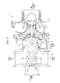
FIG. 7 , aturbocharger 100 has a structure by which external air (fresh air) inhaled through asilencer 101 is guided to anintake port 103 located before acompressor 102. Additionally, said structure does not include an intake pipe. As a result, with large turbochargers, as recited in the invention described in Patent Document 1, there is a problem in that exhaust gas cannot be circulated to the intake pipe. - Additionally, in cases where piping is connected for circulating the exhaust gas between the
intake port 103 and thecompressor 102 ofFIG. 7 , drift is generated due to the distance between theintake port 103 and thecompressor 102 being short, and deviations in the temperature of the mixed air constituted by the inhaled air and the exhaust gas are generated. - In cases where deviations in the temperature of the mixed air inhaled into the
compressor 102 occur, deviations in the density of the mixed air occur, which lead to the problem of a decline in the efficiency of theturbocharger 100. Additionally, thermal expansion occurs in thecompressor 102 into which the mixed air having temperature deviations is inhaled and, as a result, localized stress is generated which is thought to possibly lead to a decline in the reliability of theturbocharger 100. - In light of these conventional problems, an object of the present invention is to provide a turbocharger by which deviations in the temperature of mixed air constituted by recirculated exhaust gas and inhaled air can be prevented, thus enabling the suppression of declines in efficiency and declines in reliability; and to provide a diesel engine comprising this turbocharger.
- A turbocharger and a diesel engine comprising the same of the present invention employ the following means to solve the problems described above.
- Specifically, a turbocharger according to a first aspect of the present invention comprises: a turbine rotated by exhaust gas exhausted from a diesel engine, a rotating shaft having the turbine provided on a one end thereof, a compressor provided on another end of the rotating shaft, which compresses air inhaled through an intake port as a result of the rotation of the turbine, and mixing means provided upstream of the intake port. In such a turbocharger, the mixing means mix the air and a portion of the exhaust gas and guide the mixture to the intake port.
- Exhaust gas recirculation (EGR) systems, in which a portion of exhaust gas exhausted from a diesel engine is recirculated to an inlet channel connected to a turbocharger in order to reduce combustion temperature, are in practical use in small turbochargers mounted on diesel engines of motor vehicles and the like. However, in large turbochargers mounted on vessel or land-based power generation diesel engines, the intake port is provided in before the compressor and an inlet channel is not provided. As a result, in cases where the portion of the exhaust gas exhausted from the diesel engine is guided between the intake port and the compressor, drift is generated due to the distance between the intake port and the compressor being short, and deviations in temperature are generated due to a mixture of the inhaled air and the exhaust gas being uneven.
- In order to solve these problems, mixing means for mixing the air inhaled by the compressor and the portion of the exhaust gas exhausted by the diesel engine are provided upstream of the intake port of the compressor. As a result, the air and the exhaust gas can be mixed uniformly and guided to the compressor. Therefore, drift caused by the air guided to the compressor and the exhaust gas can be prevented, the air and the exhaust gas can be uniformly mixed, and air (mixed air) having a uniform temperature can be guided to the intake port. Thus, declines in the efficiency and declines in reliability of the turbocharger can be suppressed.
- With the turbocharger according to the first aspect, the mixing means may have a configuration comprising a substantially cylindrical mixing part therein, which has a plurality of holes in a side wall thereof; and an inlet by which the portion of the exhaust gas is introduced. A one end in the axial direction of the mixing part is connected to the intake port, and the air is inhaled into another end of the mixing part.
- Using the substantially cylindrical mixing part having a plurality of holes in the side wall, the one end in the axial direction of the mixing part is connected to the intake port and air is inhaled from another end. As a result, the exhaust gas guided into of the mixing means from the inlet can be guided into the mixing part from the holes provided in the side wall of the mixing part, and the air and the exhaust gas can be mixed within the mixing part. Thus, uniformly blended mixed air can be passed through the mixing part and supplied to the intake port.
- With the turbocharger according to the configuration described above, the number of the holes provided in the side wall of the mixing part facing the inlet may be less than the number of the holes provided in the side wall not facing the inlet.
- The number of holes provided in the side wall of the mixing part facing the inlet is configured to be less than the number of holes provided in the side wall not facing the inlet. As a result, the exhaust gas guided into the mixing means from the inlet can be redirected to the side wall side of the mixing part not facing the inlet and guided into the mixing part. Therefore, the exhaust gas can be uniformly mixed with the air passing through the interior of the mixing part from substantially the circumferential direction. Thus, uniformly blended mixed air can be passed through the mixing part and supplied to the intake port.
- With the turbocharger according to the configuration described above, the diameter of the holes provided in the side wall of the mixing part facing the inlet may be smaller than the diameter of the holes provided in the side wall not facing the inlet.
- The diameter of the holes provided in the side wall of the mixing part facing the inlet is configured to be smaller than the diameter of the holes provided in the side wall not facing the inlet. As a result, the exhaust gas guided into the mixing means from the inlet can be redirected to the side wall side of the mixing part not facing the inlet and guided into the mixing part. Therefore, the exhaust gas can be uniformly mixed with the air passing through the interior of the mixing part from substantially the circumferential direction. Thus, uniformly blended mixed air can be passed through the mixing part and supplied to the intake port.
- With the turbocharger according to the configuration described above, a hole area of the holes provided in the side wall of the mixing part facing the inlet may be from 0.3 times to 0.8 times a hole area of the holes provided in the side wall not facing the inlet.
- The hole area of the holes provided in the side wall of the mixing part facing the inlet is configured to be from 0.3 times to 0.8 times the hole area of the holes provided in the side wall not facing the inlet. As a result, the exhaust gas guided into the mixing means from the inlet can be redirected to the side wall side of the mixing part not facing the inlet and guided into the mixing part. Therefore, the exhaust gas can be uniformly mixed with the air passing through the interior of the mixing part from substantially the circumferential direction. Thus, uniformly blended mixed air can be passed through the mixing part and supplied to the intake port.
- With the turbocharger according to the first aspect, the mixing means is a substantially cylindrical silencer to which the air is introduced from a side wall. The silencer comprises therein a substantially conical mixing part having a plurality of holes in a side wall thereof. Moreover, the mixing part is provided such that the axial direction thereof and the axial direction of the silencer are substantially the same, and the portion of the exhaust gas exhausted from the diesel engine from another end of the substantially conical flared side is introduced.
- The silencer is configured so as to comprise therein a substantially conical mixing part having a plurality of holes in a side wall thereof, and so that the exhaust gas is introduced from the end of the substantially conical flared side. The exhaust gas guided into the mixing part from the end of the flared side is elicited from the plurality of holes provided in the side wall of the mixing part, and is uniformly mixed in the silencer with the air introduced into the silencer from the side wall of the silencer. Therefore, drift between the air guided to the compressor and the exhaust gas can be prevented, and mixed air having a uniform temperature can be guided to the intake port. Thus, decreases in the efficiency and decreases in the reliability of the turbocharger, which are caused by temperature variations in the mixed air to be supplied, can be suppressed.
- A diesel engine according to a second aspect of the present invention comprises any one of the turbochargers described above.
- Here, a turbocharger capable of inhaling uniformly blended mixed air is used. As a result, compressed mixed air that has been thoroughly mixed can be guided from the turbocharger to the diesel engine. Thus, variation between air cylinders caused by inconsistencies in the mixed air can be eliminated and performance degradation of the diesel engine can be suppressed.
- With the present invention, mixing means for mixing the air inhaled by the compressor and the portion of the exhaust gas exhausted by the diesel engine are provided upstream of the intake port of the compressor. As a result, the air and the exhaust gas can be mixed uniformly and guided to the compressor. Therefore, drift caused by the air guided to the compressor and the exhaust gas can be prevented, the air and the exhaust gas can be uniformly mixed, and air (mixed air) having a uniform temperature can be guided to the intake port. Thus, declines in the efficiency and declines in reliability of the turbocharger can be suppressed.
-
- {
Fig. 1 }
FIG. 1 is a vertical cross-sectional view illustrating a schematic configuration of a turbocharger according to a first embodiment of the present invention. - {
Fig. 2 }
FIG. 2 is a perspective view of a mixing part provided in a return gas casing of a turbocharger according to a second embodiment of the present invention. - {
Fig. 3 }
FIG. 3 is a perspective view of a mixing part provided in a return gas casing of a turbocharger according to a first modified example of the second embodiment of the present invention. - {
Fig. 4 }
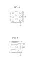
FIG. 4 is a perspective view of a mixing part provided in a return gas casing of a turbocharger according to a second modified example of the second embodiment of the present invention. - {
Fig. 5 }
FIG. 5 is a perspective view of a mixing part provided in a return gas casing of a turbocharger according to a fourth embodiment of the present invention. - {
Fig. 6 }
FIG. 6 is a vertical cross-sectional view illustrating a schematic configuration of a turbocharger according to a fifth embodiment of the present invention. - {
Fig. 7 }
FIG. 7 is a vertical cross-sectional view illustrating a schematic configuration of a conventional large turbocharger. - Hereinafter, a first embodiment of the present invention will be described while referring to
FIG. 1 . -
FIG. 1 illustrates a turbocharger 1 for mounting on a large vessel diesel engine (not illustrated) used as the main engine of a vessel. - A plurality of the turbocharger 1 is mounted on the vessel diesel engine.
- The turbocharger 1 comprises a
turbine 2 driven by exhaust gas exhausted by the vessel diesel engine, arotating shaft 6 rotated by theturbine 2, acompressor 3 that compresses air as a result of the rotation of therotating shaft 6, and a bearing stand 4 that is provided between theturbine 2 and thecompressor 3 and that supports therotating shaft 6. - The
turbine 2 comprises aturbine casing 7, aturbine disc 8 rotated by the exhaust gas (gas emissions) supplied from the vessel diesel engine, andturbine blade 9 provided in a circumferential direction of theturbine disc 8. - The
turbine casing 7 is provided so as to cover theturbine disc 8 and theturbine blade 9. Theturbine casing 7 comprises aturbine casing inlet 7a through which the exhaust gas is guided from an exhaust gas collecting pipe (not illustrated) of the vessel diesel engine, anexhaust gas passage 7b that guides the exhaust gas of the vessel diesel engine to theturbine blade 9, and a turbine casing outlet 7c that guides the exhaust gas that has passed theturbine blade 9 out of theturbine 2. - The
turbine disc 8 has a disc-like shape. A plurality of theturbine blades 9, which extend from a rotational center of theturbine disc 8 outward in the radial direction, is provided along a circumferential direction of theturbine disc 8. Theturbine blades 9 are covered by theturbine casing 7 so that an outer side in the radial direction is surrounded. The exhaust gas is guided to theturbine blade 9 from theexhaust gas passage 7b. Theturbine disc 8 and therotating shaft 6 are rotated by the exhaust gas guided to theturbine blade 9. The exhaust gas that rotated theturbine disc 8 and therotating shaft 6 is expelled from theturbine blade 9 to the turbine casing outlet 7c. - The
compressor 3 comprises acompressor casing 11 and animpeller 12 that compresses the air (fresh air) as a result of rotation thereof. - The
compressor casing 11 is provided so as to cover theimpeller 12. Thecompressor casing 11 comprises a compressor casing inlet (intake port) 11a that takes in air and exhaust gas (hereinafter referred to as "EGR gas") from outside the turbocharger 1 via asilencer 13 and a return gas casing (mixing means) 20 (described hereinafter), a volute 11b to which the air compressed by theimpeller 12 is guided, and a compressor casing outlet 11c that expels the air (fresh air) compressed by theimpeller 12. - The
impeller 12 has a substantially disc-like shape. A plurality of blades (not illustrated), which extend from the center of theimpeller 12 outward in the radial direction, is provided on a surface of theimpeller 12. Theimpeller 12 is covered such that an outer side in the radial direction thereof is surrounded by thevolute 11b. The EGR gas and the air inhaled from thecompressor casing inlet 11a are guided to theimpeller 12. Theimpeller 12 rotates as a result of the rotation of theturbine 2, which is provided on thesame shaft 6 as theimpeller 12. The EGR gas and the air inhaled from thecompressor casing inlet 11a are compressed by the rotatedimpeller 12, and the compressed air and EGR gas are output outward in the radial direction of theimpeller 12. The air and the EGR gas that have been compressed by theimpeller 12 pass through thevolute 11b and are guided out from the compressor casing outlet 11c. - The
compressor casing 11 is provided so that thereturn gas casing 20 is sandwiched between thecompressor casing 11 and thesilencer 13. Thereturn gas casing 20 comprises aninlet 20a that is open at a portion of an outer wall of thereturn gas casing 20. An EGR return pipe (not illustrated) that guides a portion of the exhaust gas of the vessel diesel engine (i.e. the EGR gas) connects to theinlet 20a. Thereturn gas casing 20 comprises a substantially cylindrical mixingpart 21 therein. - The mixing
part 21 has a substantially cylindrical shape and the diameter thereof is substantially equal to the diameter of thecompressor casing inlet 11a. A one end in the axial direction of the mixingpart 21 is connected to thecompressor casing inlet 11a, and another end is connected to thesilencer 13. As a result, the air introduced into from thesilencer 13 can pass through the interior of the mixingpart 21 to thecompressor casing inlet 11a. A plurality ofholes 22 are provided in a side wall of the mixingpart 21. Thus, the mixingpart 21 has a porous, cylindrical shape. The plurality ofholes 22 provided in the mixingpart 21 each have, for example, a substantially circular shape. - The
rotating shaft 6 penetrates the bearing stand 4. A one end of therotating shaft 6 protrudes to theturbine 2 side and another end protrudes to thecompressor 3 side. Additionally, theturbine casing 7 and thecompressor casing 11 are connected to the bearing stand 4. Theturbine casing 7, the bearing stand 4, and thecompressor casing 11 are integrally connected by a plurality of bolts (not illustrated). - Journal bearings (not illustrated) and thrust bearings (not illustrated) are provided on the bearing stand 4. The journal bearings are provided near the
turbine 2 side and near thecompressor 3 side of the bearing stand 4. The journal bearings enable rotation about the axis of therotating shaft 6. Further, therotating shaft 6 is supported by the bearing stand 4. - Furthermore, the thrust bearings, which are disposed on both sides of a thrust collar (not illustrated) that is provided so as to protrude toward an outer circumference in the radial direction of the
rotating shaft 6, makes it possible for the exhaust gas to act on theturbine blades 9 and regulate movement of therotating shaft 6 in the axial direction and also to enable rotation around therotating shaft 6. - Next, flow of the EGR gas and the air supplied by the turbocharger 1 will be explained using
FIG. 1 . - The exhaust gas is guided from the exhaust gas collecting pipe of the vessel diesel engine to the
turbine casing inlet 7a of theturbine casing 7. The exhaust gas that has been guided to theturbine casing inlet 7a is guided past through theexhaust gas passage 7b to theturbine blade 9. Theturbine disc 8 and therotating shaft 6 are rotated by the exhaust gas guided to theturbine blade 9. The exhaust gas that rotated theturbine disc 8 and therotating shaft 6 is expelled from theturbine blade 9 to the turbine casing outlet 7c. - The
impeller 12 is provided on the side of therotating shaft 6 that is opposite the side where theturbine disc 8 is provided. Therefore, theimpeller 12 is rotated as a result of the rotation of therotating shaft 6 by the exhaust gas. Air from the periphery of thesilencer 13 is inhaled into thesilencer 13 by the rotation of theimpeller 12. Further, a portion of the exhaust gas of the vessel diesel engine is guided into thereturn gas casing 20 as EGR gas from theinlet 20a of thereturn gas casing 20 that is provided between thesilencer 13 and thecompressor casing 11. - Air (fresh air) inhaled through the
silencer 13 is guided to the substantially cylindrical mixingpart 21 that is provided in thereturn gas casing 20 as a result of the rotation of theimpeller 12. Further, the EGR gas that is introduced into thereturn gas casing 20 from theinlet 20a of thereturn gas casing 20 is guided into the mixingpart 21 from the plurality ofholes 22 provided in the mixingpart 21. As a result, the EGR gas can be uniformly mixed with the air passing through the interior of the mixingpart 21. - As described above, the air and the EGR gas that are uniformly mixed in the mixing part 21 (referred to as "mixed air") are inhaled into the
compressor casing 11 from thecompressor casing inlet 11a. The mixed air inhaled into thecompressor casing 11 is compressed by the rotatingimpeller 12. The mixed air compressed by theimpeller 12 is expelled from the compressor casing outlet 11c via thevolute 11b. - Thus, the compressed mixed air expelled from the turbocharger 1 is supplied to the vessel diesel engine and, therefore, mixed air consisting of thoroughly mixed air and EGR gas is supplied to the vessel diesel engine by the turbocharger 1.
- With the turbocharger 1 and the vessel diesel engine comprising the same according to this embodiment, the following benefits are provided.
- The return gas casing (mixing means) 20, which mixes the air (fresh air) inhaled by the
compressor 3 and a portion of the exhaust gas (i.e. EGR gas) exhausted from the vessel diesel engine (diesel engine), was provided upstream of the compressor casing inlet (intake port) 11a of thecompressor 3 and between thecompressor 3 and thesilencer 13. As a result, the air and the EGR gas can be mixed uniformly and guided to thecompressor casing inlet 11a. Therefore, drift of the mixed air constituted by the air guided to thecompressor casing inlet 11a and the exhaust gas can be prevented, and mixed air having a uniform temperature can be guided to thecompressor casing inlet 11a. Thus, decreases in the efficiency and decreases in the reliability of the turbocharger 1, which are caused by temperature variations in the mixed air to be inhaled, can be suppressed. - Using the substantially cylindrical mixing
part 21 having the plurality ofholes 22 in the side wall, the one end in the axial direction of the mixingpart 21 is connected to thecompressor casing inlet 11a and air is inhaled from another end in the axial direction of the mixingpart 21. As a result, the EGR gas is guided into of the mixing means 21 from theholes 22 provided in the side wall of the mixingpart 21, and the air and the EGR gas can be mixed within the mixingpart 21. Thus, uniformly blended mixed air can be passed through the mixingpart 21 and supplied to thecompressor casing inlet 11a. - Here, the turbocharger 1 capable of inhaling uniformly blended mixed air is used. As a result, compressed mixed air that has been uniformly mixed can be guided from the turbocharger 1 to the vessel diesel engine (not illustrated). Thus, variation between air cylinders caused by inconsistencies in the mixed air can be eliminated and performance degradation of the vessel diesel engine can be suppressed.
- Note that, in this embodiment, an example was described in which the diesel engine was a vessel diesel engine, but the present invention should not be construed to be limited thereto and may be applied to a diesel engine for land-based power generation.
- A turbocharger and a vessel diesel engine comprising the same of the second embodiment are identical to those of the first embodiment with the exception that the number of holes provided in the side wall of the mixing part facing the inlet of the return gas casing differs from the number of holes provided in the side wall at other locations. Therefore, identical reference numerals are assigned to the same constituents and the flow of the EGR gas and the air, and description thereof is omitted.
-
FIG. 2 is a perspective view of the side wall of the mixing part provided in the return gas casing (mixing means) according to the second embodiment. -
FIG. 2 illustrates the side wall of the mixingpart 21 facing the inlet (not illustrated) provided in the return gas casing (not illustrated). The dashed line shown inFIG. 2 depicts ahole 22 provided in the side wall that is opposite the side wall facing the inlet. - As illustrated in
FIG. 2 , sixholes part 21 facing the inlet. - With regards to the
holes 22 provided at locations other than in the side wall of the mixingpart 21 facing the inlet, in addition to the sixholes hole 22g (as depicted by the dashed line) is provided substantially in the center of the circle formed by the sixholes - That is, the number (seven) of the
holes part 21 facing the inlet is greater than the number (six) of theholes part 21 facing the inlet. - Thus, the number of the
holes 22 provided in the side wall of the mixingpart 21 facing the inlet is configured to be less than the number of theholes 22 provided at other locations in the side wall. As a result, the EGR gas (the portion of the exhaust gas) introduced into the return gas casing from the inlet of the return gas casing migrates between the mixingpart 21 and the return gas casing, recirculates to the side opposite the inlet side, and is guided into the mixingpart 21. - Thereby, concentration of the EGR gas can be suppressed from increasing inside the mixing
part 21 on the inlet side and can be made uniform in the circumferential direction within the mixingpart 21. - With the turbocharger and the vessel diesel engine comprising the same according to the second embodiment, the following benefits are provided.
- The number (six) of the
holes part 21 facing the inlet (not illustrated) is configured to be less than the number (seven) of theholes part 21 not facing the inlet. As a result, the EGR gas (portion of the exhaust gas) guided into the return gas casing (mixing means) from the inlet can be redirected to the side wall side of the mixingpart 21 not facing the inlet and guided into the mixingpart 21. Therefore, the exhaust gas can be uniformly mixed with of the air (fresh air) passing through the interior of the mixingpart 21 from substantially the circumferential direction of the mixingpart 21. Thus, uniformly blended mixed air can be passed through the mixingpart 21 and supplied to the compressor casing inlet (intake port). - Note that, in the second embodiment, an example was described in which the
hole 22g is provided, in the side wall other than the side wall of the mixingpart 21 facing the inlet, substantially in the center of the circle formed by theholes FIG. 3 , provision of theholes 22 in the side wall of the mixingpart 21 facing the inlet, located in the vicinity of the edges in the axial direction of the mixingpart 21 may be omitted, as with a first modified example of the second embodiment. Alternately, the provision of the plurality of theholes 22 in substantially the center portion in the axial direction of the mixingpart 21 may be omitted, as with a second modified example, as illustrated by the dashed lines inFIG. 4 . - A turbocharger and a vessel diesel engine comprising the same of the third embodiment are identical to those of the first embodiment with the exception that the diameter of the holes provided in the side wall of the mixing part facing the inlet of the return gas casing is smaller than the diameter of the holes provided in the side wall at other locations. Therefore, description of identical constituents and the flow of the EGR gas and the air is omitted.
- The diameter of the holes provided in the side wall of the mixing means facing the inlet of the return gas casing (mixing means) is configured to be smaller than the diameter of the holes provided in the side wall at locations other than facing the inlet. Thus, the diameter of the holes provided in the side wall of the mixing part facing the inlet is configured to be smaller than the diameter of the holes provided at other locations in the side wall. As a result, the EGR gas (i.e. portion of the exhaust gas) introduced into the return gas casing (not illustrated) from the inlet of the return gas casing migrates between the mixing part and the return gas casing, recirculates to the side opposite the inlet side, and is guided into the mixing part.
- With the turbocharger 1 and the vessel diesel engine comprising the same according to the third embodiment, the following benefits are provided.
- The diameter of the holes provided in the side wall of the mixing part facing the inlet of the return gas casing (mixing means) is configured to be smaller than the diameter of the holes provided in the side wall not facing the inlet. As a result, the EGR gas (i.e. portion of the exhaust gas) guided into the mixing means from the inlet can be redirected to the side of the side wall not facing the inlet and guided into the mixing part. Therefore, the EGR gas can be uniformly mixed with the air (fresh air) passing through the interior of the mixing part from substantially the circumferential direction. Thus, uniformly blended mixed air can be passed through the mixing part and supplied to the compressor casing inlet (intake port).
- A turbocharger and a vessel diesel engine comprising the same of the fourth embodiment are identical to those of the first embodiment with the exception that the area of the holes provided in the side wall of the mixing part facing the inlet of the return gas casing differs from the area of the holes provided in the side wall at other locations. Therefore, identical reference numerals are assigned to the same constituents and the flow of the EGR gas and the air, and description thereof is omitted.
-
FIG. 5 is a perspective view of the side wall of the mixing part provided in the return gas casing (mixing means) according to the fourth embodiment. - As illustrated in
FIG. 5 , a plurality of substantiallyrectangular holes 23 is provided in the side wall of the mixingpart 21 so as to have a major axis in the longitudinal direction of the mixingpart 21. Therectangular holes 23 are provided in the side wall of the mixingpart 21 such that the major axes thereof are parallel with each other. - Further, in place of the substantially
rectangular holes 23, a substantiallycircular hole 22 is provided in the side wall of the mixingpart 21 facing the inlet (not illustrated) of the return gas casing (not illustrated), at a portion in the vicinity (the right side inFIG. 5 ) of the compressor casing inlet (intake port). An inner diameter of thishole 22 is substantially equivalent to the minor axis of the substantiallyrectangular holes 23, and the hole area of thehole 22 is configured to be 0.3 times the hole area of the substantially rectangular holes 23. - With the turbocharger 1 and the vessel diesel engine comprising the same according to the fourth embodiment, the following benefits are provided.
- The hole area of the
hole 22 provided in the side wall of the mixingpart 21 facing the inlet (not illustrated) of the return gas casing (mixing means) is configured to be 0.3 times the hole area of theholes 23 provided in the side wall not facing the inlet. As a result, the EGR gas (portion of the exhaust gas) guided into the mixingpart 21 from the inlet can be redirected to the side wall side of the mixingpart 21 not facing the inlet and guided into the mixingpart 21. Therefore, the exhaust gas can be uniformly mixed with the air (fresh air) passing through the interior of the mixingpart 21 from substantially the circumferential direction. Thus, uniformly blended mixed air can be passed through the mixingpart 21 and supplied to the compressor casing inlet (intake port). - Note that, in the fourth embodiment, an example was described in which the hole area of the
hole 22 provided in the side wall of the mixingpart 21 facing the inlet of the return gas casing is configured to be 0.3 times the hole area of theholes 23 provided in the side wall not facing the inlet, but the present invention shall not be construed to be limited thereto. Provided that the hole area is sufficient to enable the uniform mixing of the air and the EGR gas in the mixingpart 21, the hole area of thehole 22 may be from 0.3 times to 0.8 times the hole area of theholes 23. - A turbocharger and a vessel diesel engine comprising the same of the fifth embodiment are identical to those of the first embodiment with the exception that the mixing part is provided in the silencer. Therefore, identical reference numerals are assigned to the same constituents and the flow of the EGR gas and the air, and description thereof is omitted.
-
FIG. 6 is a vertical cross-sectional view illustrating a schematic configuration of the turbocharger according to the fifth embodiment. - A silencer (mixing means) 13 having a diameter that is substantially the same as an outer diameter of the
compressor casing 11 is provided in a compressor casing inlet (intake port) 11a of thecompressor casing 11. Thesilencer 13 has a substantially cylindrical shape, and attenuates sound as a result of air (fresh air) being introduced from a side wall thereof. Further, asilencer inlet 13a, by which EGR gas (portion of the exhaust gas) is introduced, is open on a surface of thesilencer 13 that is opposite thecompressor 3 side (the left side inFIG. 6 ). - A substantially conical mixing
part 30 is provided within thesilencer 13 described above. The mixingpart 30 comprises a plurality ofholes 31 in a side wall thereof, and the axial direction of the mixingpart 30 and the axial direction of thesilencer 13 are substantially the same. The mixingpart 30 that is provided within thesilencer 13 comprises aninlet 30a by which EGR gas exhausted from a vessel diesel engine (diesel engine) is introduced to another end on the substantially conical flared side. Theinlet 30a has a flange structure, and is fixed by bolts (not illustrated) installed from an inner side of thesilencer 13 into thesilencer inlet 13a. - The EGR gas is guided from an EGR return pipe (not illustrated) through the
silencer inlet 13a, and from theinlet 30a of the mixingpart 30 into the mixingpart 30. The EGR gas guided into the mixingpart 30 is guided into thesilencer 13 via a plurality ofholes 31 that is provided in the side wall of the mixingpart 30. - Air is inhaled from the side wall of the
silencer 13 into thesilencer 13 as a result of the rotation of thecompressor 3. The air inhaled into thesilencer 13 is mixed with the EGR gas guided via theholes 31 of the mixingpart 30, and guided to thecompressor casing inlet 11a. - With the turbocharger 1 and the vessel diesel engine comprising the same according to this embodiment, the following benefits are provided.
- The substantially conical mixing
part 30 comprising the plurality ofholes 31 in the side wall is provided within the silencer (mixing means) 13, and EGR gas (portion of the exhaust gas) is guided from theinlet 30a provided on the end of the flared side of the mixingpart 30. The EGR gas that is guided from theinlet 30a into the mixingpart 30 is guided into thesilencer 13 from the plurality ofholes 31 provided in the side wall of the mixingpart 30 and is uniformly mixed with the air (fresh air) introduced into thesilencer 13 from the side wall of thesilencer 13. Therefore, drift of the air guided to the compressor casing inlet (intake port) 11a of thecompressor 3 and the exhaust gas can be prevented, and mixed air having a uniform temperature can be guided to thecompressor casing inlet 11a. Thus, decreases in the efficiency and decreases in the reliability of the turbocharger 1, which are caused by temperature variations in the mixed air to be supplied, can be suppressed. -
- 1
- Turbocharger
- 2
- Turbine
- 3
- Compressor
- 6
- Rotating shaft
- 11a
- Compressor casing inlet (intake port)
- 20
- Return gas casing (mixing means)
- The following numbered paragraphs also form part of the disclosure:
- {1} A turbocharger comprising: a turbine rotated by exhaust gas exhausted from a diesel engine,
a rotating shaft having the turbine provided on a one end thereof,
a compressor provided on another end of the rotating shaft, which compresses air inhaled through an intake port as a result of the rotation of the turbine, and
mixing means provided upstream of the intake port; wherein
the mixing means mix the air and a portion of the exhaust gas and guide the mixture to the intake port. - {2} The turbocharger according to 1, wherein the mixing means comprise: a substantially cylindrical mixing part therein, which has a plurality of holes in a side wall thereof, and an inlet by which the portion of the exhaust gas is introduced; wherein,
a one end in the axial direction of the mixing part is connected to the intake port, and the air is inhaled into another end of the mixing part. - {3} The turbocharger according to 2, wherein the number of the holes provided in the side wall of the mixing part facing the inlet is less than a number of the holes provided in the side wall not facing the inlet.
- {4} The turbocharger according to 2 or 3, wherein the diameter of the holes provided in the side wall of the mixing part facing the inlet is smaller than the diameter of the holes provided in the side wall not facing the inlet.
- {5} The turbocharger according to any one of 2 to 4, wherein a hole area of the holes provided in the side wall of the mixing part facing the inlet is from 0.3 times to 0.8 times a hole area of the holes provided in the side wall not facing the inlet.
- {6} The turbocharger according to 1, wherein: the mixing means is a substantially cylindrical silencer to which the air is introduced from a side wall;
the silencer comprises therein a substantially conical mixing part having a plurality of holes in a side wall thereof;
the mixing part is provided such that the axial direction thereof and the axial direction of the silencer are substantially the same; and the portion of the exhaust gas exhausted from the diesel engine is introduced from another end of the substantially conical flared side. - {7} A diesel engine comprising the turbocharger according to any one of 1 to 6.
Claims (6)
- A turbocharger comprising: a turbine rotated by exhaust gas exhausted from a diesel engine,
a rotating shaft having the turbine provided on a one end thereof,
a compressor provided on another end of the rotating shaft, which compresses air inhaled through an intake port as a result of the rotation of the turbine, and
mixing means provided upstream of the intake port; wherein
the mixing means mix the air and a portion of the exhaust gas and guide the mixture to the intake port, and
the mixing means is provided between a silencer and the compressor. - The turbocharger according to claim 1, wherein the mixing means comprise: a substantially cylindrical mixing part therein, which has a plurality of holes in a side wall thereof, and an inlet by which the portion of the exhaust gas is introduced; wherein,
a one end in the axial direction of the mixing part is connected to the intake port, and the air is inhaled into another end of the mixing part. - The turbocharger according to claim 2, wherein the number of the holes provided in the side wall of the mixing part facing the inlet is less than a number of the holes provided in the side wall not facing the inlet.
- The turbocharger according to claim 2 or 3, wherein the diameter of the holes provided in the side wall of the mixing part facing the inlet is smaller than the diameter of the holes provided in the side wall not facing the inlet.
- The turbocharger according to any one of claims 2 to 4, wherein a hole area of the holes provided in the side wall of the mixing part facing the inlet is from 0.3 times to 0.8 times a hole area of the holes provided in the side wall not facing the inlet.
- A diesel engine comprising the turbocharger according to any one of claims 1 to 5.
Applications Claiming Priority (2)
| Application Number | Priority Date | Filing Date | Title |
|---|---|---|---|
| JP2011009243A JP5825791B2 (en) | 2011-01-19 | 2011-01-19 | Supercharger and diesel engine equipped with the same |
| EP12736594.8A EP2666989B1 (en) | 2011-01-19 | 2012-01-18 | Turbocharger and diesel engine comprising the same |
Related Parent Applications (2)
| Application Number | Title | Priority Date | Filing Date |
|---|---|---|---|
| EP12736594.8A Division-Into EP2666989B1 (en) | 2011-01-19 | 2012-01-18 | Turbocharger and diesel engine comprising the same |
| EP12736594.8A Division EP2666989B1 (en) | 2011-01-19 | 2012-01-18 | Turbocharger and diesel engine comprising the same |
Publications (1)
| Publication Number | Publication Date |
|---|---|
| EP2915974A1 true EP2915974A1 (en) | 2015-09-09 |
Family
ID=46515769
Family Applications (2)
| Application Number | Title | Priority Date | Filing Date |
|---|---|---|---|
| EP12736594.8A Active EP2666989B1 (en) | 2011-01-19 | 2012-01-18 | Turbocharger and diesel engine comprising the same |
| EP14200071.0A Withdrawn EP2915974A1 (en) | 2011-01-19 | 2012-01-18 | Turbocharger and diesel engine comprising the same |
Family Applications Before (1)
| Application Number | Title | Priority Date | Filing Date |
|---|---|---|---|
| EP12736594.8A Active EP2666989B1 (en) | 2011-01-19 | 2012-01-18 | Turbocharger and diesel engine comprising the same |
Country Status (5)
| Country | Link |
|---|---|
| EP (2) | EP2666989B1 (en) |
| JP (1) | JP5825791B2 (en) |
| KR (5) | KR20170044217A (en) |
| CN (2) | CN103038477B (en) |
| WO (1) | WO2012099146A1 (en) |
Families Citing this family (16)
| Publication number | Priority date | Publication date | Assignee | Title |
|---|---|---|---|---|
| JP6000077B2 (en) * | 2012-11-09 | 2016-09-28 | 三菱重工業株式会社 | Exhaust turbine support structure |
| DE102013003418A1 (en) * | 2013-02-28 | 2014-08-28 | Volkswagen Aktiengesellschaft | Internal combustion engine |
| JP6071813B2 (en) * | 2013-09-06 | 2017-02-01 | 三菱重工業株式会社 | Supercharger |
| JP6056748B2 (en) * | 2013-12-20 | 2017-01-11 | トヨタ自動車株式会社 | Supercharged engine EGR system |
| JP2015124760A (en) * | 2013-12-27 | 2015-07-06 | 大豊工業株式会社 | Gas mixing device |
| JP6133770B2 (en) * | 2013-12-27 | 2017-05-24 | 大豊工業株式会社 | Gas mixing equipment |
| JP6223859B2 (en) * | 2014-02-24 | 2017-11-01 | 三菱重工業株式会社 | Supercharger and motor cooling method |
| DE102014212606B4 (en) * | 2014-06-30 | 2020-12-17 | Ford Global Technologies, Llc | Motor vehicle and air filter box |
| JP6392103B2 (en) * | 2014-12-09 | 2018-09-19 | 三菱重工業株式会社 | Sound absorber, centrifugal compressor, and supercharger |
| DE102014019147A1 (en) * | 2014-12-19 | 2016-06-23 | Daimler Ag | Air line for an intake of an internal combustion engine, in particular a motor vehicle |
| CN105114217A (en) * | 2015-09-29 | 2015-12-02 | 安徽江淮汽车股份有限公司 | EGR waste gas mixing mechanism |
| US10132216B2 (en) | 2016-05-31 | 2018-11-20 | Progress Rail Locomotive Inc. | Crankcase ventilation system for an internal combustion engine |
| JP6841645B2 (en) * | 2016-12-12 | 2021-03-10 | 三菱重工業株式会社 | EGR system and diesel engine |
| GB2568234B (en) * | 2017-10-30 | 2021-12-08 | Zehnder Group Lenham Ltd | Domestic ventilation fan with tapering projections for reducing turbulence |
| CN108730073A (en) * | 2018-03-26 | 2018-11-02 | 北京理工大学 | A kind of high-pressure exhaust-gas recirculation system of supercharged diesel engine engine |
| EP4400710A1 (en) * | 2023-01-10 | 2024-07-17 | Innio Jenbacher GmbH & Co OG | Gas mixer for an internal combustion engine |
Citations (8)
| Publication number | Priority date | Publication date | Assignee | Title |
|---|---|---|---|---|
| NL298027A (en) * | 1900-01-01 | |||
| JPS51120315A (en) * | 1975-04-15 | 1976-10-21 | Mitsubishi Heavy Ind Ltd | Air intake sound absorbing device for exhaust turbine supercharger |
| JPH05195893A (en) * | 1992-01-20 | 1993-08-03 | Toushiyou Eng Kk | Variable passage sectional area type silencer |
| DE10002581A1 (en) * | 2000-01-21 | 2001-08-02 | Man B & W Diesel Ag | Turbocharger for gas fuelled engines has gas passage openings in air induction pipe of compressor for feed of gas and located in region of smallest diameter |
| US20070271920A1 (en) * | 2006-05-24 | 2007-11-29 | Honeywell International, Inc. | Exhaust gas recirculation mixer |
| JP2009511797A (en) | 2005-10-10 | 2009-03-19 | ベール ゲーエムベーハー ウント コー カーゲー | Device for recirculation and cooling of exhaust gas from internal combustion engines |
| WO2009068181A1 (en) * | 2007-11-28 | 2009-06-04 | Borgwarner Inc. | Turbo charger |
| EP2110531A1 (en) * | 2007-02-09 | 2009-10-21 | Mitsubishi Heavy Industries, Ltd. | Exhaust gas turbocharger |
Family Cites Families (10)
| Publication number | Priority date | Publication date | Assignee | Title |
|---|---|---|---|---|
| US3892070A (en) * | 1970-05-08 | 1975-07-01 | Ranendra K Bose | Automobile anti-air pollution device |
| DE60018041T2 (en) * | 2000-05-05 | 2005-07-28 | Siemens Ag | Method and device for recirculating exhaust gas into the intake air flow |
| JP2002180913A (en) * | 2000-12-08 | 2002-06-26 | Yamaha Motor Co Ltd | EGR structure |
| ITTO20030179A1 (en) * | 2003-03-11 | 2004-09-12 | Fiat Auto Spa | PROCEDURE FOR REMOVING THE PARTICULATE FROM GAS |
| ITMI20030571A1 (en) * | 2003-03-21 | 2004-09-22 | Kleen Up S R L | POST-COMBUSTION PROCESS THROUGH IRRADIANCE AND FILTRATION FOR THE ELIMINATION OF HARMFUL POLLUTANTS, DUST, GAS AND CHARCOAL PARTICULATES OF THE EMISSIONS OF DIESEL AND PETROL ENGINES, AS WELL AS THE BURNER FOR HEATING AND / / HEAVY OIL HEATING |
| CN100436808C (en) * | 2003-04-01 | 2008-11-26 | Avl里斯脱有限公司 | Method and device for driving direct injection diesel engine |
| JP2004360547A (en) | 2003-06-04 | 2004-12-24 | Arupatec Kk | Silencer for supercharger |
| US7614232B2 (en) * | 2004-07-23 | 2009-11-10 | General Electric Company | Turbocharger recirculation valve |
| CN101578439B (en) * | 2007-02-05 | 2011-11-16 | 博格华纳公司 | Turbocharger |
| JP5813017B2 (en) * | 2010-02-17 | 2015-11-17 | ボーグワーナー インコーポレーテッド | Turbocharger |
-
2011
- 2011-01-19 JP JP2011009243A patent/JP5825791B2/en active Active
-
2012
- 2012-01-18 KR KR1020177010369A patent/KR20170044217A/en not_active Ceased
- 2012-01-18 KR KR1020167002261A patent/KR20160017118A/en not_active Ceased
- 2012-01-18 WO PCT/JP2012/050911 patent/WO2012099146A1/en not_active Ceased
- 2012-01-18 EP EP12736594.8A patent/EP2666989B1/en active Active
- 2012-01-18 KR KR1020147024217A patent/KR20140111351A/en not_active Ceased
- 2012-01-18 KR KR1020137002448A patent/KR101506820B1/en active Active
- 2012-01-18 EP EP14200071.0A patent/EP2915974A1/en not_active Withdrawn
- 2012-01-18 CN CN201280002213.7A patent/CN103038477B/en active Active
- 2012-01-18 CN CN201410471888.7A patent/CN104314667A/en active Pending
- 2012-01-18 KR KR1020187011965A patent/KR20180049829A/en not_active Ceased
Patent Citations (8)
| Publication number | Priority date | Publication date | Assignee | Title |
|---|---|---|---|---|
| NL298027A (en) * | 1900-01-01 | |||
| JPS51120315A (en) * | 1975-04-15 | 1976-10-21 | Mitsubishi Heavy Ind Ltd | Air intake sound absorbing device for exhaust turbine supercharger |
| JPH05195893A (en) * | 1992-01-20 | 1993-08-03 | Toushiyou Eng Kk | Variable passage sectional area type silencer |
| DE10002581A1 (en) * | 2000-01-21 | 2001-08-02 | Man B & W Diesel Ag | Turbocharger for gas fuelled engines has gas passage openings in air induction pipe of compressor for feed of gas and located in region of smallest diameter |
| JP2009511797A (en) | 2005-10-10 | 2009-03-19 | ベール ゲーエムベーハー ウント コー カーゲー | Device for recirculation and cooling of exhaust gas from internal combustion engines |
| US20070271920A1 (en) * | 2006-05-24 | 2007-11-29 | Honeywell International, Inc. | Exhaust gas recirculation mixer |
| EP2110531A1 (en) * | 2007-02-09 | 2009-10-21 | Mitsubishi Heavy Industries, Ltd. | Exhaust gas turbocharger |
| WO2009068181A1 (en) * | 2007-11-28 | 2009-06-04 | Borgwarner Inc. | Turbo charger |
Also Published As
| Publication number | Publication date |
|---|---|
| KR20160017118A (en) | 2016-02-15 |
| WO2012099146A1 (en) | 2012-07-26 |
| EP2666989B1 (en) | 2015-12-09 |
| KR20130021468A (en) | 2013-03-05 |
| KR20140111351A (en) | 2014-09-18 |
| JP2012149579A (en) | 2012-08-09 |
| EP2666989A4 (en) | 2014-07-02 |
| KR101506820B1 (en) | 2015-03-27 |
| CN103038477B (en) | 2015-04-22 |
| KR20180049829A (en) | 2018-05-11 |
| CN104314667A (en) | 2015-01-28 |
| CN103038477A (en) | 2013-04-10 |
| JP5825791B2 (en) | 2015-12-02 |
| KR20170044217A (en) | 2017-04-24 |
| EP2666989A1 (en) | 2013-11-27 |
Similar Documents
| Publication | Publication Date | Title |
|---|---|---|
| EP2666989B1 (en) | Turbocharger and diesel engine comprising the same | |
| US8262342B2 (en) | Gas turbine engine assemblies with recirculated hot gas ingestion | |
| KR101833111B1 (en) | Control device for denitration device, denitration device, and control method for denitration device | |
| RU2628166C2 (en) | Method for operation of gas-turbine power plant with spent gas recycling and corresponding gas-turbine power plant | |
| US20090196739A1 (en) | Axial flow fluid device | |
| US12264821B2 (en) | Aircraft engine for nitrogen oxide reduction | |
| JP2010127239A (en) | Marine diesel engine | |
| JP6041943B2 (en) | Marine diesel engine supercharger and marine diesel engine equipped with the same | |
| CN116234976B (en) | Turbine housing, turbocharger, and gasoline engine | |
| KR20150100346A (en) | EGR booster for exhaust gas recirculation system | |
| GB2564689B (en) | An EGR apparatus with a turbocharger and an EGR compressor | |
| EP3284917B1 (en) | Active clearance control collector to manifold insert | |
| CN105492738A (en) | Turbine, turbocharger, internal combustion engine, and ship | |
| RU2861201C2 (en) | Ventilation system of gas turbine package and method for ventilating gas turbine package | |
| JP2019148240A (en) | Turbocharger | |
| GB2564691B (en) | An EGR system having a turbine driven auxiliary compressor | |
| JP2024139252A (en) | Compressor housing, compressor and turbocharger | |
| CN114651120A (en) | gas turbine engine |
Legal Events
| Date | Code | Title | Description |
|---|---|---|---|
| PUAI | Public reference made under article 153(3) epc to a published international application that has entered the european phase |
Free format text: ORIGINAL CODE: 0009012 |
|
| AC | Divisional application: reference to earlier application |
Ref document number: 2666989 Country of ref document: EP Kind code of ref document: P |
|
| AK | Designated contracting states |
Kind code of ref document: A1 Designated state(s): AL AT BE BG CH CY CZ DE DK EE ES FI FR GB GR HR HU IE IS IT LI LT LU LV MC MK MT NL NO PL PT RO RS SE SI SK SM TR |
|
| 17P | Request for examination filed |
Effective date: 20160303 |
|
| RBV | Designated contracting states (corrected) |
Designated state(s): AL AT BE BG CH CY CZ DE DK EE ES FI FR GB GR HR HU IE IS IT LI LT LU LV MC MK MT NL NO PL PT RO RS SE SI SK SM TR |
|
| 17Q | First examination report despatched |
Effective date: 20170324 |
|
| RAP1 | Party data changed (applicant data changed or rights of an application transferred) |
Owner name: MITSUBISHI HEAVY INDUSTRIES, LTD. Owner name: JAPAN ENGINE CORPORATION |
|
| STAA | Information on the status of an ep patent application or granted ep patent |
Free format text: STATUS: THE APPLICATION IS DEEMED TO BE WITHDRAWN |
|
| 18D | Application deemed to be withdrawn |
Effective date: 20190625 |