EP2915781A1 - Saturator and water treating apparatus including the same - Google Patents
Saturator and water treating apparatus including the same Download PDFInfo
- Publication number
- EP2915781A1 EP2915781A1 EP15151339.7A EP15151339A EP2915781A1 EP 2915781 A1 EP2915781 A1 EP 2915781A1 EP 15151339 A EP15151339 A EP 15151339A EP 2915781 A1 EP2915781 A1 EP 2915781A1
- Authority
- EP
- European Patent Office
- Prior art keywords
- water
- saturator
- flow path
- fluid
- compressed air
- Prior art date
- Legal status (The legal status is an assumption and is not a legal conclusion. Google has not performed a legal analysis and makes no representation as to the accuracy of the status listed.)
- Granted
Links
Images


Classifications
-
- C—CHEMISTRY; METALLURGY
- C02—TREATMENT OF WATER, WASTE WATER, SEWAGE, OR SLUDGE
- C02F—TREATMENT OF WATER, WASTE WATER, SEWAGE, OR SLUDGE
- C02F1/00—Treatment of water, waste water, or sewage
- C02F1/24—Treatment of water, waste water, or sewage by flotation
-
- B—PERFORMING OPERATIONS; TRANSPORTING
- B01—PHYSICAL OR CHEMICAL PROCESSES OR APPARATUS IN GENERAL
- B01D—SEPARATION
- B01D21/00—Separation of suspended solid particles from liquids by sedimentation
- B01D21/0084—Enhancing liquid-particle separation using the flotation principle
-
- B—PERFORMING OPERATIONS; TRANSPORTING
- B01—PHYSICAL OR CHEMICAL PROCESSES OR APPARATUS IN GENERAL
- B01F—MIXING, e.g. DISSOLVING, EMULSIFYING OR DISPERSING
- B01F23/00—Mixing according to the phases to be mixed, e.g. dispersing or emulsifying
- B01F23/20—Mixing gases with liquids
- B01F23/23—Mixing gases with liquids by introducing gases into liquid media, e.g. for producing aerated liquids
- B01F23/231—Mixing gases with liquids by introducing gases into liquid media, e.g. for producing aerated liquids by bubbling
- B01F23/23105—Arrangement or manipulation of the gas bubbling devices
- B01F23/2312—Diffusers
- B01F23/23124—Diffusers consisting of flexible porous or perforated material, e.g. fabric
- B01F23/231244—Dissolving, hollow fiber membranes
-
- B—PERFORMING OPERATIONS; TRANSPORTING
- B01—PHYSICAL OR CHEMICAL PROCESSES OR APPARATUS IN GENERAL
- B01F—MIXING, e.g. DISSOLVING, EMULSIFYING OR DISPERSING
- B01F23/00—Mixing according to the phases to be mixed, e.g. dispersing or emulsifying
- B01F23/20—Mixing gases with liquids
- B01F23/23—Mixing gases with liquids by introducing gases into liquid media, e.g. for producing aerated liquids
- B01F23/231—Mixing gases with liquids by introducing gases into liquid media, e.g. for producing aerated liquids by bubbling
- B01F23/23105—Arrangement or manipulation of the gas bubbling devices
- B01F23/2312—Diffusers
- B01F23/23126—Diffusers characterised by the shape of the diffuser element
- B01F23/231265—Diffusers characterised by the shape of the diffuser element being tubes, tubular elements, cylindrical elements or set of tubes
-
- B—PERFORMING OPERATIONS; TRANSPORTING
- B03—SEPARATION OF SOLID MATERIALS USING LIQUIDS OR USING PNEUMATIC TABLES OR JIGS; MAGNETIC OR ELECTROSTATIC SEPARATION OF SOLID MATERIALS FROM SOLID MATERIALS OR FLUIDS; SEPARATION BY HIGH-VOLTAGE ELECTRIC FIELDS
- B03D—FLOTATION; DIFFERENTIAL SEDIMENTATION
- B03D1/00—Flotation
- B03D1/14—Flotation machines
- B03D1/1431—Dissolved air flotation machines
-
- C—CHEMISTRY; METALLURGY
- C02—TREATMENT OF WATER, WASTE WATER, SEWAGE, OR SLUDGE
- C02F—TREATMENT OF WATER, WASTE WATER, SEWAGE, OR SLUDGE
- C02F2301/00—General aspects of water treatment
- C02F2301/02—Fluid flow conditions
- C02F2301/026—Spiral, helicoidal, radial
-
- C—CHEMISTRY; METALLURGY
- C02—TREATMENT OF WATER, WASTE WATER, SEWAGE, OR SLUDGE
- C02F—TREATMENT OF WATER, WASTE WATER, SEWAGE, OR SLUDGE
- C02F2301/00—General aspects of water treatment
- C02F2301/02—Fluid flow conditions
- C02F2301/028—Tortuous
-
- C—CHEMISTRY; METALLURGY
- C02—TREATMENT OF WATER, WASTE WATER, SEWAGE, OR SLUDGE
- C02F—TREATMENT OF WATER, WASTE WATER, SEWAGE, OR SLUDGE
- C02F2301/00—General aspects of water treatment
- C02F2301/04—Flow arrangements
- C02F2301/046—Recirculation with an external loop
Definitions
- the present disclosure relates to a saturator and a water treating apparatus including the same, and particularly, to a saturator which dissolves air in water, and to a water treating apparatus which removes a foreign material by floating dissolved air in a water treating operation with the saturator.
- a water treating apparatus is an apparatus that produces fresh water with seawater, obtains living water, drinking water, and industrial water, or appropriately treats raw water for purifying waste water.
- the water treating apparatus includes an apparatus for removing a foreign material which is mixed with raw water.
- An example of an apparatus for removing a foreign material includes a dissolved air floating apparatus.
- the dissolved air floating apparatus is an apparatus that agglutinates a foreign material by mixing a medicine (e.g. a coagulant) with raw water to be treated, and floats the agglutinated foreign material along with an air bubble to remove the agglutinated foreign material.
- a medicine e.g. a coagulant
- the dissolved air floating apparatus includes a reaction and agglutination tank 10, a floatation tank 20, a circulation pump 60, an air compressor 50, and a saturator 30.
- raw water to be treated is mixed with an agglutination agent and an agglutination aid, and thus, a particulate material or a floating material, having a relatively low density, such as an organic compound and algae contained in the raw water, is agglutinated.
- An agitator 11 for mixing an agglutination agent with a foreign material contained in raw water to generate a floc may be provided in the reaction and agglutination tank 10.
- Water passing through the reaction and agglutination tank 10 flows into the floatation tank 20, an air bubble is adsorbed onto the floc, and a combined body thereof floats onto a water surface.
- water in which air is oversaturated in the saturator 30 is depressurized through a nozzle 40 which is provided in the floatation tank 20, and flows into the floatation tank 20, thereby producing the air bubble.
- the air compressor 50 supplies compressed air to the saturator 30.
- Water from which foreign materials such as sludge and a floating material are removed in the floatation tank 20 moves to a water purifying apparatus 70, or is supplied to the saturator 30 through the circulation pump 60.
- the saturator 30 is an apparatus for dissolving compressed air in water which flows into the apparatus through the circulation pump 60.
- a water collecting space 32 is formed at a lower portion of the related art saturator, and a filler 31 is filled on the water collecting space 32.
- the compressed air and the water flows from an upper end of the saturator 30 into the inside, and the compressed air is dissolved in the water while the compressed air and the water is passing through the filler 31, whereby the compressed air and the water are collected in the water collecting space 32. Therefore, the related art saturator has a vertical long shape.
- dissolving efficiency is determined based on a shape of a filler or a filling amount, and thus, the saturator is designed to have a higher height for increasing the dissolving efficiency. Also, the dissolving efficiency is proportional to a residence time in the water collecting space 32, and thus, the saturator is designed so that the water in which the compressed air is dissolved remains in the water collecting space 32 for as long as possible. Therefore, the related art saturator is configured with a pressure vessel which has a high height and a large volume.
- the related art saturator when the related art saturator is applied to a dissolved air floating apparatus having a relatively large capacity, the related art saturator is disposed on the reaction and agglutination tank 10 or the floatation tank 20 so as to shorten a pipe distance to the nozzle 40.
- a flow rate of the circulated water is determined based on a pressure of the saturator 30 and the number of nozzles which are provided in the floatation tank 20. Therefore, when desiring to change a flow rate of the circulated water in a state of maintaining the pressure of the saturator 30, the number of nozzles should be changed after an operation of a water treating apparatus stops.
- an aspect of the detailed description is to provide a saturator and a water treating apparatus including the same, in which a contact area is enlarged when compressed air is dissolved in water in the saturator, thereby enhancing dissolving efficiency.
- Another aspect of the detailed description is to provide a saturator and a water treating apparatus including the same, in which a speed where compressed air is dissolved in water in the saturator becomes faster, thereby enhancing dissolving efficiency.
- Another aspect of the detailed description is to provide a saturator and a water treating apparatus including the same, in which the saturator is freely disposed, and a space in which the saturator is disposed is small.
- Another aspect of the detailed description is to provide a saturator and a water treating apparatus including the same, in which a flow rate of water which circulates between the saturator and a floatation apparatus is easily adjusted.
- a saturator includes: a chamber in which a first flow path through which first fluid flows is formed; and a plurality of porous membranes disposed in the first flow path, and in which a second flow path through which second fluid flows is formed, wherein the first fluid is dissolved in the second fluid, or the second fluid is dissolved in the first fluid.
- the chamber may be formed in a pipe shape.
- the plurality of porous membranes may transmit one of the first and second fluids, and may not transmit the other fluid.
- the first flow path may extend in parallel with the second flow path.
- the first flow path may extend to intersect the second flow path a plurality of times, and the first fluid may flow to produce a vortex.
- the first flow path may intersect the second flow path a plurality of times, and thus, a vortex of the first fluid may be produced around the plurality of porous membranes. Accordingly, a speed in which the second fluid is dissolved in the first fluid becomes faster.
- the first flow path may be formed by a partition wall which extends from a wall to an inner side of the chamber.
- a plurality of through holes may be formed at the partition wall, and thus, when the first fluid flows, a vortex can be easily produced.
- a water treating apparatus includes: a saturator configured to include a chamber, in which a first flow path is formed, and a plurality of porous membranes disposed in the first flow path and in which a second flow path is formed, wherein compressed water is dissolved in water in the saturator; an air compressor configured to supply the compressed air to the saturator; a water supply apparatus configured to supply the water to the saturator; and a floatation apparatus configured to include a space in which dissolved air of the water supplied from the saturator floats in combination with a foreign material.
- the chamber may be formed in a pipe shape.
- the plurality of porous membranes may transmit the compressed air, and may not transmit the water.
- the water supply apparatus may include a pump configured to supply the water to the saturator, and a flow rate of the water supplied from the saturator to the floatation apparatus may be adjusted by the pump.
- the pump may supply at least some of the water, passing through the floatation apparatus, to the saturator.
- the air compressor may supply the compressed air to the first flow path, and the water supply apparatus may supply the water to the second flow path.
- the air compressor may supply the compressed air to the second flow path, and the water supply apparatus may supply the water to the first flow path.
- the first flow path may extend in parallel with the second flow path.
- the first flow path may extend to intersect the second flow path a plurality of times, and the first fluid may flow to produce a vortex.
- the first flow path may be formed by a partition wall which extends from a wall to an inner side of the chamber. A plurality of through holes may be formed at the partition wall, and thus, when the first fluid flows, a vortex can be easily produced.
- the partition wall may spirally extend in an extension direction of the second flow path.
- a plurality of the partition walls may be alternately disposed at a facing inner wall surface of the chamber, and thus, the first flow path may be formed in zigzags.
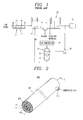
- FIG. 2 is a perspective view illustrating a saturator according to a first embodiment of the present invention.
- FIG. 3 is a cross-section view taken along line I - I of FIG. 2 .
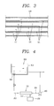
- FIG. 4 is a diagram schematically illustrating a water treating apparatus according to a first embodiment of the present invention.
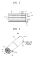
- FIG. 5 is a cross-sectional view illustrating a state in which a saturator of FIG. 4 is connected to an air compressor and a water inlet pipe.
- a saturator and a water treating apparatus including the same according to an embodiment of the present invention will be described in detail with reference to FIGS. 2 to 5 .
- a saturator 100 according to a first embodiment of the present invention is an apparatus into which first fluid and second fluid flow and in which the first fluid and the second fluid are dissolved.
- the saturator 100 includes a chamber 110, in which a first flow path is formed, and a plurality of porous membranes 120 which are disposed in the first flow path and in which a second flow path is formed.
- the first fluid flowing into the saturator 100 according to the first embodiment is compressed air
- the second fluid is water.
- saturated water water in which the compressed air is dissolved in the saturator 100
- an upstream and a downstream of a flow path are defined with respect to a direction in which water flows.
- the chamber 110 is a pipe in which the first flow path 111 is formed, and the first fluid (i.e., the compressed air) may move through the first flow path.
- the chamber 110 is a cylinder in which a hollow space is formed, and the hollow space is a first flow path 111.
- a shape of the chamber 110 is not limited thereto, and the chamber 110 may have any shape which enables the compressed air to be dissolved in water.
- the chamber 110 may be formed as a pipe having a polygonal cross-section.
- the chamber 110 may further include a first fluid inflow part 113 which communicates with the first flow path 111 at an upstream of the first flow path 111. Compressed air may be supplied to the first flow path 111 through the first fluid inflow part 113.
- the first fluid inflow part 113 may be formed in a pipe shape at a side wall of an upstream side of the chamber 110, and may be provided so that the compressed air is supplied from a side of the chamber 110 to the first flow path 111.
- the present embodiment is not limited thereto.
- the first fluid inflow part 113 may be provided to communicate with the first flow path 111 at a side end of the upstream side of the chamber 110, and the compressed air may flow from one end of the first flow path 111 into the first fluid inflow part 113.
- the first fluid inflow part 113 may be provided in plurality depending on the case.
- a plurality of second fluid inflow parts 115 and 117 may be further formed at an end adjacent to the first fluid inflow part 113.
- the second fluid inflow parts 115 and 117 are formed so that water supplied to the saturator 100 is transferred to a second flow path 121 through a water path 201.
- the second fluid inflow parts 115 and 117 may include a connection part 115, which connects the water path 201 to an upstream side end of the chamber 110, and a blocking membrane 117 which blocks a space between the connection part 115 and the first flow path 111 so that water flowing from the water path 201 flows into only the second flow path 121 without flowing into the first flow path 111.
- a through hole into which an end of the porous membrane 120 is inserted may be formed at the blocking membrane 117, and the connection part 115 fluid-communicates with the second flow path 121. Therefore, water flowing into the connection part 115 is not supplied to the first flow path 111 but is supplied to only the second flow path 121.
- a shape of each of the second fluid inflow parts 115 and 117 is not limited thereto, and the second fluid inflow parts 115 and 117 may have all shapes in which water supplied from the water path 201 to the saturator 100 flows into the second flow path 121 without flowing into the first flow path 111.
- the second flow path 121 may be formed in the porous membrane 120, and the second fluid (i.e., the water) may move through the second flow path 121.
- the porous membrane 120 may be a cylindrical membrane in which a hollow space is formed, and the hollow space may be the second flow path 121.
- the porous membrane 120 may be an angular membrane.
- the porous membrane 120 may be provided in plurality in the first flow path 111, and the plurality of porous membranes 120 may be arranged in parallel at certain intervals, and may extend in a direction in which the first flow path 111 extends.
- the porous membrane 120 may be a membrane in which a pore is formed in plurality at a wall.
- the pore may be formed so that the compressed air flowing in the first flow path 111 passes through the porous membrane 120, but the water flowing in the second flow path 121 hardly passes through the porous membrane 120. Therefore, the pore formed at the porous member 120 may have a size of 50 ⁇ m or less, and for example, have a size having a range of 1 ⁇ m to 100 ⁇ m. When a size of the pore formed at the porous membrane 120 is less than 1 ⁇ m, pressure loss occurs, and when the size of the pore formed at the porous membrane 120 is 500 ⁇ m or more, water freely passes through the porous membrane 120.
- the porous membrane 120 may be formed of a plastic material such as poly ethylene (PE).
- An inner diameter of the porous membrane 120 for determining a cross-sectional area of the second flow path 121, the number of the porous membranes 120 included in the first flow path 111, and a length of the porous membrane 120 may be determined based on a flow rate necessary for water treatment and a degree to which compressed air is dissolved in water.
- Compressed air may be supplied to the first flow path 111 through the first fluid inflow part 113.
- air which is compressed at two bars or more may be supplied as the compressed air.
- water may be supplied to the second flow path 121 through the second fluid inflow part 115.
- the compressed air may flow through the first flow path 111, pass through the porous membrane 120, and move to the second flow path 121.
- the water may flow through the second flow path 121 in the same direction as a direction in which the compressed air flows, and the compressed air is dissolved in the water to produce saturated water.
- the saturator according to an embodiment of the present invention has a structure in which the porous membrane is provided in the chamber having a pipe shape, the saturator according to an embodiment of the present invention is not particularly high, unlike the related art saturator, and may be disposed to be horizontal or to be inclined.
- the compressed air is directly supplied to the first flow path, and the water is directly supplied to the second flow path. Therefore, a measurement apparatus such as a water gauge is not needed, and thus, a configuration is simple.
- a measurement apparatus such as a water gauge is not needed, and thus, a configuration is simple.
- water and compressed air flow into a space filled with a filler at an upper end of the saturator, and thus, the measurement apparatus such as the water gauge is needed.
- the measurement apparatus is not needed since the compressed air is supplied to the first flow path, and the water is supplied to the second flow path.
- the water treating apparatus includes a saturator 100, a water supply apparatus, an air compressor 210, and a floatation apparatus 300.
- the saturator 100 is the above-described saturator according to the first embodiment, and thus, its detailed description is not provided.
- the floatation apparatus 300 is an apparatus in which saturated water produced in the saturator 100 flows into the floatation apparatus 300 to produce an air bubble, and a foreign material of treated water filled in the floatation apparatus 300 floats in combination with the air bubble.
- the floatation apparatus 300 may include a treated water tank 310, in which a space where a foreign material is removed while treated water is flowing is formed, and a nozzle 320 which is disposed under the treated water tank 310.
- the saturated water produced in the saturator 100 may be supplied to the nozzle 320, and a pressure of the saturated water may increase in the nozzle 320 to produce an air bubble.
- the floatation apparatus 300 is a known element, and thus, its detailed description is not provided.
- the water supply apparatus may supply water from an external water source to the saturator 100, or supply some of treated water, passing through the floatation apparatus 300, to the saturator 100.
- a case of supplying water passing through the floatation apparatus 300 will be described.
- the water supply apparatus may include a pump 220, which pumps water, discharged from the floatation apparatus 300, to the saturator 100, and a water path 201 through which the water flows from the floatation apparatus 300 to the saturator 100 due to the pump 220.
- the water supply apparatus may further include a control unit that controls the pump 220 to adjust a flow rate of the saturated water.
- the first fluid inflow part 113 and the second fluid inflow parts 115 and 117 are separately provided in the saturator 100 according to the present embodiment, the first fluid is supplied to the first flow path, and the second fluid is supplied to the second flow path. Therefore, when desiring to adjust the flow rate of the saturated water in a state of maintaining an internal pressure of the saturator 100, the flow rate of the saturated water is simply adjusted by controlling the pump 220. Accordingly, the flow rate of the saturated water is adjusted without adjusting the number of the nozzles 320.
- the water path 201 may be connected to the second fluid inflow parts 115 and 117, and the water supply apparatus may supply water. As described above, the water path 201 may communicate with the second flow path 121, and may not communicate with the first flow path 111. Therefore, water may flow into the second flow path 121 through the water path 201.
- the air compressor 210 may supply compressed air to the saturator 100.
- the air compressor 210 may supply air, which is compressed at two bars or more, to the saturator 100.
- a compressed air flow path 211 in which compressed air flows may communicate with the first fluid inflow part 113, and the compressed air may be supplied to the first flow path 111.
- the air compressor 210 may have an arbitrary configuration in which air is compressed at two bars or more, and is supplied. A detailed configuration of the air compressor 210 has been known to those skilled in the art, and thus, its detailed description is not provided.
- the saturator 100 may be supplied with water from the water supply apparatus, may be supplied with the compressed air from the air compressor 210, and may dissolve the compressed air in the water. As described above, the compressed air may flow through the first flow path 111, pass through the porous membrane 120, flow into the second flow path 121, and may be dissolved in the water which flows in the second flow path 121. At this time, the compressed air and the water may flow in the same direction to produce saturated water.
- a saturated water supply path 202 may extend from a downstream of the saturator 100 to the nozzle 320, and supply the saturated water to the nozzle 320.
- the saturated water supply path 202 may directly connect the saturator 100 to a header of the nozzle 320.
- pressure loss is reduced, and thus, more micro air bubbles are produced through the nozzle 320.
- the saturator 100 since the saturator 100 has a pipe shape, it is not required to install the floatation apparatus 300 in a building, and thus, the installation cost and the maintenance cost can be reduced. In addition, air conditioning equipment or fire fighting equipment are not needed, and thus, facilities or elements necessary for the water treating apparatus according to an embodiment of the present invention are simplified.
- a saturator 500 according to a second embodiment of the present invention is an apparatus into which first fluid and second fluid flow and in which the second fluid is dissolved in the first fluid.
- the saturator 500 according to the second embodiment of the present invention includes a chamber 510, in which a first flow path is formed, and a plurality of porous membranes 520 which is disposed in the first flow path and in which a second flow path is formed.
- the first fluid flowing into the saturator 500 according to the second embodiment is water
- the second fluid is compressed air.
- saturated water water in which the compressed air is dissolved in the saturator 500
- an upstream and a downstream of a flow path are defined with respect to a direction in which water flows.
- the chamber 510 is a pipe in which a first flow path 511 is formed, and the first fluid (i.e., the water) may move through the first flow path.
- the chamber 510 is a cylinder in which a hollow space is formed, and the hollow space is the first flow path 511.
- a shape of the chamber 510 is not limited thereto, and may be modified.
- the chamber 510 may further include a first fluid inflow part 516, which communicates with the first flow path 511, and a second fluid outflow part 518. Water may be supplied to the first flow path 511 through the first fluid inflow part 516, and water in which compressed air is dissolved while flowing in the first flow path 511 may be discharged to the first fluid outflow part 518.
- the first fluid inflow part 516 may be formed in a pipe shape at a side wall of an upstream side of the chamber 510, and the first fluid outflow part 518 may be formed in a pipe shape at a side wall of a downstream side of the chamber 510.
- An installation position and a shape of each of the first fluid inflow part 516 and the first fluid outflow part 518 are not limited thereto, and the first fluid inflow part 516 and the first fluid outflow part 518 may be modified to various shapes in which water is supplied to the first flow path 511 and saturated water is discharged.
- each of the first fluid inflow part 516 and the first fluid outflow part 518 may be provided in plurality.
- a second flow path 521 may be formed in each of the plurality of porous membranes 520, and the second fluid (i.e., the compressed air) may move through the second flow path 521.
- the second fluid i.e., the compressed air
- a physical feature and a shape of each of the plurality of porous membranes 520 are the same as those of the porous membrane 120 according to the first embodiment of the present invention, and thus, their detailed descriptions are not provided.
- the second embodiment has a difference in that compressed air flows through the second flow path 521, passes through the porous membrane 520, and moves to the first flow path 511.
- the chamber 510 may further include a second fluid inflow part 519.
- the second fluid inflow part 519 has the same function and shape as those of the second fluid inflow parts 115 and 117 described above with reference to FIG. 5 .
- a connection part may be connected to the compressed air flow path 211 of the air compressor 210, and compressed air may be supplied to the second flow path 521.
- water may be supplied to the first flow path 511 through the first fluid inflow part 516, and compressed air may be supplied to the second flow path 521 through the second fluid inflow part 519.
- compressed air which is compressed at two bars or more may be supplied as the compressed air.
- the compressed air may flow through the second flow path 521, pass through the porous membrane 520, and move to the first flow path 511.
- the water may flow through the first flow path 511 in the same direction as a direction in which the compressed air flows, and the compressed air may be dissolved in the water to produce saturated water.
- FIGS. 8 to 10 illustrate modification examples 530, 530', and 530" of a chamber.
- a modification example of the chamber will be described in detail with reference to FIGS. 8 to 10 .
- a chamber 530 may have a shape in which a first flow path 531 extends by intersecting a second flow path 521 a plurality of times. To this end, the chamber 530 may further include a plurality of partition walls 532a and 532b.
- the partition walls 532a and 532b may extend from an inner wall surface of the chamber 530 to an opposite inner wall surface, and one end of each of the partition walls 532a and 532b may be separated from the opposite inner wall surface.
- the partition walls 532a and 532b may extend to cross the porous membrane 520. In other words, the partition walls 532a and 532b may extend to be vertical to an extension direction of the porous membrane 520.
- the plurality of porous membranes 520 may be provided so that a plurality of porous membranes 520 pass through one of the partition walls 532a and 532b.
- the plurality of porous membranes 520 may be provided so that one porous membrane 520 passes through the plurality of partition walls 532a and 532b.
- the partition wall 532b which is disposed next to the partition wall 532a may extend from an inner wall surface opposite to an inner wall surface in which the partition wall 532a is disposed.
- a plurality of partition walls may alternately extend from opposite inner wall surfaces to an inner side, and the first flow path 531 may be formed to extend in zigzags.
- water flowing through the first flow path 531 meets the second flow path 521 a plurality of times, and moreover, the first flow path 531 is formed in zigzags, whereby a vortex or a warm current is actively produced by a flow of water. Accordingly, a speed in which compressed air is dissolved in water becomes faster.
- FIG. 9 illustrates a modification embodiment in which a vortex and a warm current are more produced when water flows through a first flow path 531', and is a cross-sectional view illustrating a chamber 530' in which a plurality of through holes 533a and 533b are formed at the partition walls 532a and 532b. Water may flow through the partition walls 532a and 532b due to the through holes 533a and 533b, and thus, a vortex and a warm current are more produced.
- a shape of each of the partition walls 532a and 532b is not limited thereto, and may be modified to all shapes in which a vortex is more produced by a flow of fluid.
- each of the partition walls 532a and 532b may be formed in a wave shape.
- FIG. 10 is a partial cross-sectional view illustrating a chamber 530" in which a partition wall 535 is formed in a spiral shape.
- the partition wall 535 may be a plate shape which spirally extends in a direction where water flows.
- One porous membrane 520 may extend to pass through the partition wall 535 a plurality of times.
- a spiral outer border of the partition wall 535 may be fixed to an inner wall surface of the chamber 530". Therefore, a first flow path 531" having a spiral shape may be formed between a plurality of the partition walls 535, and may intersect a second flow path a plurality of times.
- FIG. 11 is a diagram schematically illustrating some elements of a water treating apparatus including the saturator 500 according to the above-described embodiment.
- a water treating apparatus according to a second embodiment of the present invention may be an apparatus in which the above-described saturator 500 is provided in the water treating apparatus of FIG. 4 .
- the water treating apparatus according to the second embodiment of the present invention may include the saturator 500, the water supply apparatus, the air compressor 210, and the floatation apparatus 300.
- the saturator 500 and the floatation apparatus 300 are as described above.
- the first fluid inflow part 516 may be connected to the water path 201, and water may be supplied to the saturator 500. Therefore, the water path 201 may communicate with the first flow path 511, and may not communicate with the second flow path 521. Therefore, the water may flow into the first flow path 511 through the water path 201.
- the water supply apparatus may include a pump 220, and details relevant to the pump 220 have been described above. Thus, a detailed description is not provided.
- the air compressor 210 may supply compressed air to the saturator 500.
- the air compressor 210 may supply air, which is compressed at two bars or more, to the saturator 500. Referring to FIG. 11 , in the air compressor 210, the compressed air flow path 211 in which compressed air flows may communicate with the second fluid inflow part 119, and supply the compressed air to the second flow path 521.
- the air compressor 210 is as described above, and thus, its detailed description is not provided.
- the saturator 500 may be supplied with water from the water supply apparatus, may be supplied with the compressed air from the air compressor 210, and may dissolve the compressed air in the water. As described above, the compressed air may flow through the second flow path 521, pass through the porous membrane 520, flow into the first flow paths 511 and 531, and may be dissolved in the water which flows in the first flow path. At this time, the compressed air and the water may flow in the same direction to produce saturated water.
- the saturated water supply path 202 may extend from the first fluid outflow part 518 to the nozzle 320, and supply the saturated water to the nozzle 320.
- FIG. 12 is a diagram illustrating a water treating apparatus when a plurality of the saturators 500 are connected in series.
- the plurality of saturators 500 may be connected in series for increasing a degree to which compressed air is dissolved in water.
- the first fluid inflow part 516 of the saturator 500 which is disposed at an uppermost stream may be connected to the water path 201, and the first fluid outflow part 518 may be connected to a first fluid inflow part of a next saturator.
- the first fluid inflow part of the next saturator may be connected to a first fluid inflow part of a saturator subsequent thereto. Connections are made in this way, and a first fluid inflow part of a last saturator may be connected to the saturated water supply path 202.
- the plurality of saturators 500 is connected in parallel, and thus increases a whole flow rate of saturated water.
- a contact area is enlarged when compressed air is dissolved in water, and thus, dissolving efficiency is enhanced.
- the saturator is freely disposed, and the installation cost and the maintenance cost are reduced.
- a flow rate of saturated water supplied to the floatation apparatus is simply adjusted by controlling the pump.
- a warm current is produced by a flow of fluid, and thus, a dissolving speed becomes faster.
Landscapes
- Chemical & Material Sciences (AREA)
- Chemical Kinetics & Catalysis (AREA)
- Life Sciences & Earth Sciences (AREA)
- Hydrology & Water Resources (AREA)
- Engineering & Computer Science (AREA)
- Environmental & Geological Engineering (AREA)
- Water Supply & Treatment (AREA)
- Organic Chemistry (AREA)
- Physical Water Treatments (AREA)
Abstract
Description
- The present disclosure relates to a saturator and a water treating apparatus including the same, and particularly, to a saturator which dissolves air in water, and to a water treating apparatus which removes a foreign material by floating dissolved air in a water treating operation with the saturator.
- Generally, a water treating apparatus is an apparatus that produces fresh water with seawater, obtains living water, drinking water, and industrial water, or appropriately treats raw water for purifying waste water. The water treating apparatus includes an apparatus for removing a foreign material which is mixed with raw water.
- An example of an apparatus for removing a foreign material includes a dissolved air floating apparatus. The dissolved air floating apparatus is an apparatus that agglutinates a foreign material by mixing a medicine (e.g. a coagulant) with raw water to be treated, and floats the agglutinated foreign material along with an air bubble to remove the agglutinated foreign material. Referring to
FIG. 1 , the dissolved air floating apparatus includes a reaction andagglutination tank 10, afloatation tank 20, acirculation pump 60, anair compressor 50, and asaturator 30. - In the reaction and
agglutination tank 10, raw water to be treated is mixed with an agglutination agent and an agglutination aid, and thus, a particulate material or a floating material, having a relatively low density, such as an organic compound and algae contained in the raw water, is agglutinated. Anagitator 11 for mixing an agglutination agent with a foreign material contained in raw water to generate a floc may be provided in the reaction andagglutination tank 10. - Water passing through the reaction and
agglutination tank 10 flows into thefloatation tank 20, an air bubble is adsorbed onto the floc, and a combined body thereof floats onto a water surface. At this time, water in which air is oversaturated in thesaturator 30 is depressurized through anozzle 40 which is provided in thefloatation tank 20, and flows into thefloatation tank 20, thereby producing the air bubble. Theair compressor 50 supplies compressed air to thesaturator 30. Water from which foreign materials such as sludge and a floating material are removed in thefloatation tank 20 moves to a water purifyingapparatus 70, or is supplied to thesaturator 30 through thecirculation pump 60. - The
saturator 30 is an apparatus for dissolving compressed air in water which flows into the apparatus through thecirculation pump 60. In a related art saturator, awater collecting space 32 is formed at a lower portion of the related art saturator, and afiller 31 is filled on thewater collecting space 32. The compressed air and the water flows from an upper end of thesaturator 30 into the inside, and the compressed air is dissolved in the water while the compressed air and the water is passing through thefiller 31, whereby the compressed air and the water are collected in thewater collecting space 32. Therefore, the related art saturator has a vertical long shape. - In the related art saturator, dissolving efficiency is determined based on a shape of a filler or a filling amount, and thus, the saturator is designed to have a higher height for increasing the dissolving efficiency. Also, the dissolving efficiency is proportional to a residence time in the
water collecting space 32, and thus, the saturator is designed so that the water in which the compressed air is dissolved remains in thewater collecting space 32 for as long as possible. Therefore, the related art saturator is configured with a pressure vessel which has a high height and a large volume. Also, when the related art saturator is applied to a dissolved air floating apparatus having a relatively large capacity, the related art saturator is disposed on the reaction andagglutination tank 10 or thefloatation tank 20 so as to shorten a pipe distance to thenozzle 40. - Therefore, a height of a building in which a dissolved air floating apparatus including the related art saturator is provided becomes wholly high, and for this reason, much cost is expended in installation and operation.
- Moreover, in the related art saturator, water is circulated between the
floatation tank 20 and thesaturator 30 by thecirculation pump 60. In this case, a flow rate of the circulated water is determined based on a pressure of thesaturator 30 and the number of nozzles which are provided in thefloatation tank 20. Therefore, when desiring to change a flow rate of the circulated water in a state of maintaining the pressure of thesaturator 30, the number of nozzles should be changed after an operation of a water treating apparatus stops. - Therefore, an aspect of the detailed description is to provide a saturator and a water treating apparatus including the same, in which a contact area is enlarged when compressed air is dissolved in water in the saturator, thereby enhancing dissolving efficiency.
- Another aspect of the detailed description is to provide a saturator and a water treating apparatus including the same, in which a speed where compressed air is dissolved in water in the saturator becomes faster, thereby enhancing dissolving efficiency.
- Another aspect of the detailed description is to provide a saturator and a water treating apparatus including the same, in which the saturator is freely disposed, and a space in which the saturator is disposed is small.
- Another aspect of the detailed description is to provide a saturator and a water treating apparatus including the same, in which a flow rate of water which circulates between the saturator and a floatation apparatus is easily adjusted.
- To achieve these and other advantages and in accordance with the purpose of this specification, as embodied and broadly described herein, a saturator includes: a chamber in which a first flow path through which first fluid flows is formed; and a plurality of porous membranes disposed in the first flow path, and in which a second flow path through which second fluid flows is formed, wherein the first fluid is dissolved in the second fluid, or the second fluid is dissolved in the first fluid.
- The chamber may be formed in a pipe shape. The plurality of porous membranes may transmit one of the first and second fluids, and may not transmit the other fluid.
- The first flow path may extend in parallel with the second flow path.
- Alternatively, the first flow path may extend to intersect the second flow path a plurality of times, and the first fluid may flow to produce a vortex. As described above, the first flow path may intersect the second flow path a plurality of times, and thus, a vortex of the first fluid may be produced around the plurality of porous membranes. Accordingly, a speed in which the second fluid is dissolved in the first fluid becomes faster.
- The first flow path may be formed by a partition wall which extends from a wall to an inner side of the chamber. A plurality of through holes may be formed at the partition wall, and thus, when the first fluid flows, a vortex can be easily produced.
- In another aspect of the present invention, a water treating apparatus includes: a saturator configured to include a chamber, in which a first flow path is formed, and a plurality of porous membranes disposed in the first flow path and in which a second flow path is formed, wherein compressed water is dissolved in water in the saturator; an air compressor configured to supply the compressed air to the saturator; a water supply apparatus configured to supply the water to the saturator; and a floatation apparatus configured to include a space in which dissolved air of the water supplied from the saturator floats in combination with a foreign material.
- The chamber may be formed in a pipe shape. The plurality of porous membranes may transmit the compressed air, and may not transmit the water.
- The water supply apparatus may include a pump configured to supply the water to the saturator, and a flow rate of the water supplied from the saturator to the floatation apparatus may be adjusted by the pump. In this case, the pump may supply at least some of the water, passing through the floatation apparatus, to the saturator.
- The air compressor may supply the compressed air to the first flow path, and the water supply apparatus may supply the water to the second flow path. Alternatively, the air compressor may supply the compressed air to the second flow path, and the water supply apparatus may supply the water to the first flow path.
- The first flow path may extend in parallel with the second flow path.
- Alternatively, the first flow path may extend to intersect the second flow path a plurality of times, and the first fluid may flow to produce a vortex. In this case, the first flow path may be formed by a partition wall which extends from a wall to an inner side of the chamber. A plurality of through holes may be formed at the partition wall, and thus, when the first fluid flows, a vortex can be easily produced.
- The partition wall may spirally extend in an extension direction of the second flow path. Alternatively, a plurality of the partition walls may be alternately disposed at a facing inner wall surface of the chamber, and thus, the first flow path may be formed in zigzags.
- Further scope of applicability of the present application will become more apparent from the detailed description given hereinafter. However, it should be understood that the detailed description and specific examples, while indicating preferred embodiments of the disclosure, are given by way of illustration only, since various changes and modifications within the spirit and scope of the disclosure will become apparent to those skilled in the art from the detailed description.
- The accompanying drawings, which are included to provide a further understanding of the disclosure and are incorporated in and constitute a part of this specification, illustrate exemplary embodiments and together with the description serve to explain the principles of the disclosure.
- In the drawings:
-
FIG. 1 is a diagram schematically illustrating a related art dissolved air floating apparatus; -
FIG. 2 is a perspective view illustrating a saturator according to a first embodiment of the present invention; -
FIG. 3 is a cross-section view taken along line I - I ofFIG. 2 ; -
FIG. 4 is a diagram schematically illustrating a water treating apparatus according to a first embodiment of the present invention; -
FIG. 5 is a cross-sectional view illustrating a state in which a saturator ofFIG. 4 is connected to an air compressor and a water inlet pipe; -
FIG. 6 is a perspective view illustrating a saturator according to a second embodiment of the present invention; -
FIG. 7 is a cross-sectional view taken along line II - II ofFIG. 6 ; -
FIG. 8 is a cross-sectional view illustrating a modification embodiment of a chamber ofFIG. 7 ; -
FIG. 9 is a cross-sectional view illustrating another embodiment of a partition wall ofFIG. 8 ; -
FIG. 10 is a cross-sectional view illustrating another embodiment of the partition wall ofFIG. 8 ; -
FIG. 11 is a diagram schematically illustrating some elements of a water treating apparatus according to a second embodiment of the present invention; and -
FIG. 12 is a diagram schematically illustrating some elements of a water treating apparatus according to a third embodiment of the present invention. - Description will now be given in detail of the exemplary embodiments, with reference to the accompanying drawings. For the sake of brief description with reference to the drawings, the same or equivalent components will be provided with the same reference numbers, and description thereof will not be repeated.
- Exemplary embodiments of the present invention capable of being easily embodied by those skilled in the art will now be described in detail with reference to the accompanying drawings. In the following description, when the detailed description of the relevant known function or configuration is determined to unnecessarily obscure the important point of the present invention, the detailed description will be omitted.
-
FIG. 2 is a perspective view illustrating a saturator according to a first embodiment of the present invention.FIG. 3 is a cross-section view taken along line I - I ofFIG. 2 .FIG. 4 is a diagram schematically illustrating a water treating apparatus according to a first embodiment of the present invention.FIG. 5 is a cross-sectional view illustrating a state in which a saturator ofFIG. 4 is connected to an air compressor and a water inlet pipe. A saturator and a water treating apparatus including the same according to an embodiment of the present invention will be described in detail with reference toFIGS. 2 to 5 . - A
saturator 100 according to a first embodiment of the present invention is an apparatus into which first fluid and second fluid flow and in which the first fluid and the second fluid are dissolved. Thesaturator 100 includes achamber 110, in which a first flow path is formed, and a plurality ofporous membranes 120 which are disposed in the first flow path and in which a second flow path is formed. The first fluid flowing into thesaturator 100 according to the first embodiment is compressed air, and the second fluid is water. Hereinafter, water in which the compressed air is dissolved in thesaturator 100 is referred to as saturated water. Also, an upstream and a downstream of a flow path are defined with respect to a direction in which water flows. - The
chamber 110 is a pipe in which thefirst flow path 111 is formed, and the first fluid (i.e., the compressed air) may move through the first flow path. Specifically, thechamber 110 is a cylinder in which a hollow space is formed, and the hollow space is afirst flow path 111. However, a shape of thechamber 110 is not limited thereto, and thechamber 110 may have any shape which enables the compressed air to be dissolved in water. For example, thechamber 110 may be formed as a pipe having a polygonal cross-section. - The
chamber 110 may further include a firstfluid inflow part 113 which communicates with thefirst flow path 111 at an upstream of thefirst flow path 111. Compressed air may be supplied to thefirst flow path 111 through the firstfluid inflow part 113. Referring toFIG. 2 , the firstfluid inflow part 113 may be formed in a pipe shape at a side wall of an upstream side of thechamber 110, and may be provided so that the compressed air is supplied from a side of thechamber 110 to thefirst flow path 111. However, the present embodiment is not limited thereto. For example, the firstfluid inflow part 113 may be provided to communicate with thefirst flow path 111 at a side end of the upstream side of thechamber 110, and the compressed air may flow from one end of thefirst flow path 111 into the firstfluid inflow part 113. Also, the firstfluid inflow part 113 may be provided in plurality depending on the case. - Referring to
FIG. 5 , in thechamber 110, a plurality of secondfluid inflow parts fluid inflow part 113. The secondfluid inflow parts saturator 100 is transferred to asecond flow path 121 through awater path 201. The secondfluid inflow parts connection part 115, which connects thewater path 201 to an upstream side end of thechamber 110, and a blockingmembrane 117 which blocks a space between theconnection part 115 and thefirst flow path 111 so that water flowing from thewater path 201 flows into only thesecond flow path 121 without flowing into thefirst flow path 111. A through hole into which an end of theporous membrane 120 is inserted may be formed at the blockingmembrane 117, and theconnection part 115 fluid-communicates with thesecond flow path 121. Therefore, water flowing into theconnection part 115 is not supplied to thefirst flow path 111 but is supplied to only thesecond flow path 121. - A shape of each of the second
fluid inflow parts fluid inflow parts water path 201 to thesaturator 100 flows into thesecond flow path 121 without flowing into thefirst flow path 111. - The
second flow path 121 may be formed in theporous membrane 120, and the second fluid (i.e., the water) may move through thesecond flow path 121. Theporous membrane 120 may be a cylindrical membrane in which a hollow space is formed, and the hollow space may be thesecond flow path 121. Theporous membrane 120 may be an angular membrane. Theporous membrane 120 may be provided in plurality in thefirst flow path 111, and the plurality ofporous membranes 120 may be arranged in parallel at certain intervals, and may extend in a direction in which thefirst flow path 111 extends. - The
porous membrane 120 may be a membrane in which a pore is formed in plurality at a wall. In this case, the pore may be formed so that the compressed air flowing in thefirst flow path 111 passes through theporous membrane 120, but the water flowing in thesecond flow path 121 hardly passes through theporous membrane 120. Therefore, the pore formed at theporous member 120 may have a size of 50 µm or less, and for example, have a size having a range of 1 µm to 100 µm. When a size of the pore formed at theporous membrane 120 is less than 1 µm, pressure loss occurs, and when the size of the pore formed at theporous membrane 120 is 500 µm or more, water freely passes through theporous membrane 120. Theporous membrane 120 may be formed of a plastic material such as poly ethylene (PE). - An inner diameter of the
porous membrane 120 for determining a cross-sectional area of thesecond flow path 121, the number of theporous membranes 120 included in thefirst flow path 111, and a length of theporous membrane 120 may be determined based on a flow rate necessary for water treatment and a degree to which compressed air is dissolved in water. - An operation in which compressed air is dissolved in water in the
saturator 100 will now be described. Compressed air may be supplied to thefirst flow path 111 through the firstfluid inflow part 113. In this case, air which is compressed at two bars or more may be supplied as the compressed air. Also, water may be supplied to thesecond flow path 121 through the secondfluid inflow part 115. The compressed air may flow through thefirst flow path 111, pass through theporous membrane 120, and move to thesecond flow path 121. The water may flow through thesecond flow path 121 in the same direction as a direction in which the compressed air flows, and the compressed air is dissolved in the water to produce saturated water. - According to the above-described configuration, a contact area between water and compressed air is enlarged, and thus, a saturation rate is enhanced. Also, since the saturator according to an embodiment of the present invention has a structure in which the porous membrane is provided in the chamber having a pipe shape, the saturator according to an embodiment of the present invention is not particularly high, unlike the related art saturator, and may be disposed to be horizontal or to be inclined.
- Moreover, according to the above-description configuration, the compressed air is directly supplied to the first flow path, and the water is directly supplied to the second flow path. Therefore, a measurement apparatus such as a water gauge is not needed, and thus, a configuration is simple. In the related art saturator, water and compressed air flow into a space filled with a filler at an upper end of the saturator, and thus, the measurement apparatus such as the water gauge is needed. However, since the compressed air is supplied to the first flow path, and the water is supplied to the second flow path, the measurement apparatus is not needed.
- Referring to
FIG. 4 , the water treating apparatus according to the first embodiment of the present invention includes asaturator 100, a water supply apparatus, anair compressor 210, and afloatation apparatus 300. Thesaturator 100 is the above-described saturator according to the first embodiment, and thus, its detailed description is not provided. - The
floatation apparatus 300 is an apparatus in which saturated water produced in thesaturator 100 flows into thefloatation apparatus 300 to produce an air bubble, and a foreign material of treated water filled in thefloatation apparatus 300 floats in combination with the air bubble. Thefloatation apparatus 300 may include a treatedwater tank 310, in which a space where a foreign material is removed while treated water is flowing is formed, and anozzle 320 which is disposed under the treatedwater tank 310. The saturated water produced in thesaturator 100 may be supplied to thenozzle 320, and a pressure of the saturated water may increase in thenozzle 320 to produce an air bubble. Thefloatation apparatus 300 is a known element, and thus, its detailed description is not provided. - The water supply apparatus may supply water from an external water source to the
saturator 100, or supply some of treated water, passing through thefloatation apparatus 300, to thesaturator 100. In the present embodiment, a case of supplying water passing through thefloatation apparatus 300 will be described. - The water supply apparatus may include a
pump 220, which pumps water, discharged from thefloatation apparatus 300, to thesaturator 100, and awater path 201 through which the water flows from thefloatation apparatus 300 to thesaturator 100 due to thepump 220. - Moreover, the water supply apparatus may further include a control unit that controls the
pump 220 to adjust a flow rate of the saturated water. As described above, the firstfluid inflow part 113 and the secondfluid inflow parts saturator 100 according to the present embodiment, the first fluid is supplied to the first flow path, and the second fluid is supplied to the second flow path. Therefore, when desiring to adjust the flow rate of the saturated water in a state of maintaining an internal pressure of thesaturator 100, the flow rate of the saturated water is simply adjusted by controlling thepump 220. Accordingly, the flow rate of the saturated water is adjusted without adjusting the number of thenozzles 320. - The
water path 201 may be connected to the secondfluid inflow parts water path 201 may communicate with thesecond flow path 121, and may not communicate with thefirst flow path 111. Therefore, water may flow into thesecond flow path 121 through thewater path 201. - The
air compressor 210 may supply compressed air to thesaturator 100. Theair compressor 210 may supply air, which is compressed at two bars or more, to thesaturator 100. Referring toFIG. 5 , in theair compressor 210, a compressedair flow path 211 in which compressed air flows may communicate with the firstfluid inflow part 113, and the compressed air may be supplied to thefirst flow path 111. Theair compressor 210 may have an arbitrary configuration in which air is compressed at two bars or more, and is supplied. A detailed configuration of theair compressor 210 has been known to those skilled in the art, and thus, its detailed description is not provided. - The
saturator 100 may be supplied with water from the water supply apparatus, may be supplied with the compressed air from theair compressor 210, and may dissolve the compressed air in the water. As described above, the compressed air may flow through thefirst flow path 111, pass through theporous membrane 120, flow into thesecond flow path 121, and may be dissolved in the water which flows in thesecond flow path 121. At this time, the compressed air and the water may flow in the same direction to produce saturated water. A saturatedwater supply path 202 may extend from a downstream of thesaturator 100 to thenozzle 320, and supply the saturated water to thenozzle 320. - The saturated
water supply path 202 may directly connect thesaturator 100 to a header of thenozzle 320. When thesaturator 100 is connected to the header of thenozzle 320, pressure loss is reduced, and thus, more micro air bubbles are produced through thenozzle 320. - As described above, since the
saturator 100 has a pipe shape, it is not required to install thefloatation apparatus 300 in a building, and thus, the installation cost and the maintenance cost can be reduced. In addition, air conditioning equipment or fire fighting equipment are not needed, and thus, facilities or elements necessary for the water treating apparatus according to an embodiment of the present invention are simplified. - A
saturator 500 according to a second embodiment of the present invention is an apparatus into which first fluid and second fluid flow and in which the second fluid is dissolved in the first fluid. Thesaturator 500 according to the second embodiment of the present invention includes achamber 510, in which a first flow path is formed, and a plurality ofporous membranes 520 which is disposed in the first flow path and in which a second flow path is formed. The first fluid flowing into thesaturator 500 according to the second embodiment is water, and the second fluid is compressed air. Hereinafter, water in which the compressed air is dissolved in thesaturator 500 is referred to as saturated water. Also, an upstream and a downstream of a flow path are defined with respect to a direction in which water flows. - The
chamber 510 is a pipe in which afirst flow path 511 is formed, and the first fluid (i.e., the water) may move through the first flow path. In detail, thechamber 510 is a cylinder in which a hollow space is formed, and the hollow space is thefirst flow path 511. However, a shape of thechamber 510 is not limited thereto, and may be modified. - The
chamber 510 may further include a firstfluid inflow part 516, which communicates with thefirst flow path 511, and a secondfluid outflow part 518. Water may be supplied to thefirst flow path 511 through the firstfluid inflow part 516, and water in which compressed air is dissolved while flowing in thefirst flow path 511 may be discharged to the firstfluid outflow part 518. - Referring to
FIG. 6 , the firstfluid inflow part 516 may be formed in a pipe shape at a side wall of an upstream side of thechamber 510, and the firstfluid outflow part 518 may be formed in a pipe shape at a side wall of a downstream side of thechamber 510. An installation position and a shape of each of the firstfluid inflow part 516 and the firstfluid outflow part 518 are not limited thereto, and the firstfluid inflow part 516 and the firstfluid outflow part 518 may be modified to various shapes in which water is supplied to thefirst flow path 511 and saturated water is discharged. Also, each of the firstfluid inflow part 516 and the firstfluid outflow part 518 may be provided in plurality. - A
second flow path 521 may be formed in each of the plurality ofporous membranes 520, and the second fluid (i.e., the compressed air) may move through thesecond flow path 521. A physical feature and a shape of each of the plurality ofporous membranes 520 are the same as those of theporous membrane 120 according to the first embodiment of the present invention, and thus, their detailed descriptions are not provided. However, in comparison with the first embodiment, the second embodiment has a difference in that compressed air flows through thesecond flow path 521, passes through theporous membrane 520, and moves to thefirst flow path 511. - Referring to
FIG. 11 , thechamber 510 may further include a secondfluid inflow part 519. The secondfluid inflow part 519 has the same function and shape as those of the secondfluid inflow parts FIG. 5 . However, unlike the above description, a connection part may be connected to the compressedair flow path 211 of theair compressor 210, and compressed air may be supplied to thesecond flow path 521. - An operation in which compressed air is dissolved in water in the
saturator 500 will now be described. First, water may be supplied to thefirst flow path 511 through the firstfluid inflow part 516, and compressed air may be supplied to thesecond flow path 521 through the secondfluid inflow part 519. In this case, air which is compressed at two bars or more may be supplied as the compressed air. The compressed air may flow through thesecond flow path 521, pass through theporous membrane 520, and move to thefirst flow path 511. The water may flow through thefirst flow path 511 in the same direction as a direction in which the compressed air flows, and the compressed air may be dissolved in the water to produce saturated water. - Effects of the above-described configuration are the same as those of the first embodiment.
-
FIGS. 8 to 10 illustrate modification examples 530, 530', and 530" of a chamber. A modification example of the chamber will be described in detail with reference toFIGS. 8 to 10 . Achamber 530 may have a shape in which afirst flow path 531 extends by intersecting a second flow path 521 a plurality of times. To this end, thechamber 530 may further include a plurality ofpartition walls - The
partition walls chamber 530 to an opposite inner wall surface, and one end of each of thepartition walls partition walls porous membrane 520. In other words, thepartition walls porous membrane 520. Referring toFIG. 8 , the plurality ofporous membranes 520 may be provided so that a plurality ofporous membranes 520 pass through one of thepartition walls porous membranes 520 may be provided so that oneporous membrane 520 passes through the plurality ofpartition walls partition wall 532a extends from the inner wall surface of thechamber 530 to an opposite inner wall surface, thepartition wall 532b which is disposed next to thepartition wall 532a may extend from an inner wall surface opposite to an inner wall surface in which thepartition wall 532a is disposed. In this way, a plurality of partition walls may alternately extend from opposite inner wall surfaces to an inner side, and thefirst flow path 531 may be formed to extend in zigzags. - According to the above-described configuration, water flowing through the
first flow path 531 meets the second flow path 521 a plurality of times, and moreover, thefirst flow path 531 is formed in zigzags, whereby a vortex or a warm current is actively produced by a flow of water. Accordingly, a speed in which compressed air is dissolved in water becomes faster. -
FIG. 9 illustrates a modification embodiment in which a vortex and a warm current are more produced when water flows through a first flow path 531', and is a cross-sectional view illustrating a chamber 530' in which a plurality of throughholes partition walls partition walls holes partition walls holes partition walls partition walls -
FIG. 10 is a partial cross-sectional view illustrating achamber 530" in which apartition wall 535 is formed in a spiral shape. Thepartition wall 535 may be a plate shape which spirally extends in a direction where water flows. Oneporous membrane 520 may extend to pass through the partition wall 535 a plurality of times. A spiral outer border of thepartition wall 535 may be fixed to an inner wall surface of thechamber 530". Therefore, afirst flow path 531" having a spiral shape may be formed between a plurality of thepartition walls 535, and may intersect a second flow path a plurality of times. -
FIG. 11 is a diagram schematically illustrating some elements of a water treating apparatus including thesaturator 500 according to the above-described embodiment. A water treating apparatus according to a second embodiment of the present invention may be an apparatus in which the above-describedsaturator 500 is provided in the water treating apparatus ofFIG. 4 . The water treating apparatus according to the second embodiment of the present invention may include thesaturator 500, the water supply apparatus, theair compressor 210, and thefloatation apparatus 300. Thesaturator 500 and thefloatation apparatus 300 are as described above. - In the water supply apparatus, the first
fluid inflow part 516 may be connected to thewater path 201, and water may be supplied to thesaturator 500. Therefore, thewater path 201 may communicate with thefirst flow path 511, and may not communicate with thesecond flow path 521. Therefore, the water may flow into thefirst flow path 511 through thewater path 201. Also, the water supply apparatus may include apump 220, and details relevant to thepump 220 have been described above. Thus, a detailed description is not provided. - The
air compressor 210 may supply compressed air to thesaturator 500. Theair compressor 210 may supply air, which is compressed at two bars or more, to thesaturator 500. Referring toFIG. 11 , in theair compressor 210, the compressedair flow path 211 in which compressed air flows may communicate with the second fluid inflow part 119, and supply the compressed air to thesecond flow path 521. Theair compressor 210 is as described above, and thus, its detailed description is not provided. - The
saturator 500 may be supplied with water from the water supply apparatus, may be supplied with the compressed air from theair compressor 210, and may dissolve the compressed air in the water. As described above, the compressed air may flow through thesecond flow path 521, pass through theporous membrane 520, flow into thefirst flow paths water supply path 202 may extend from the firstfluid outflow part 518 to thenozzle 320, and supply the saturated water to thenozzle 320. -
FIG. 12 is a diagram illustrating a water treating apparatus when a plurality of thesaturators 500 are connected in series. Detailed configurations of thesaturator 500, the water supply apparatus, thefloatation apparatus 300, and theair compressor 210 are as described above. The plurality ofsaturators 500 may be connected in series for increasing a degree to which compressed air is dissolved in water. In this case, the firstfluid inflow part 516 of thesaturator 500 which is disposed at an uppermost stream may be connected to thewater path 201, and the firstfluid outflow part 518 may be connected to a first fluid inflow part of a next saturator. The first fluid inflow part of the next saturator may be connected to a first fluid inflow part of a saturator subsequent thereto. Connections are made in this way, and a first fluid inflow part of a last saturator may be connected to the saturatedwater supply path 202. Alternatively, although not shown, the plurality ofsaturators 500 is connected in parallel, and thus increases a whole flow rate of saturated water. - According to the embodiments of the present invention, a contact area is enlarged when compressed air is dissolved in water, and thus, dissolving efficiency is enhanced.
- Moreover, according to the embodiments of the present invention, the saturator is freely disposed, and the installation cost and the maintenance cost are reduced.
- Moreover, according to the embodiments of the present invention, a flow rate of saturated water supplied to the floatation apparatus is simply adjusted by controlling the pump.
- Moreover, according to the embodiments of the present invention, a warm current is produced by a flow of fluid, and thus, a dissolving speed becomes faster.
- The foregoing embodiments and advantages are merely exemplary and are not to be considered as limiting the present disclosure. The present teachings can be readily applied to other types of apparatuses. This description is intended to be illustrative, and not to limit the scope of the claims. Many alternatives, modifications, and variations will be apparent to those skilled in the art. The features, structures, methods, and other characteristics of the exemplary embodiments described herein may be combined in various ways to obtain additional and/or alternative exemplary embodiments.
- As the present features may be embodied in several forms without departing from the characteristics thereof, it should also be understood that the above-described embodiments are not limited by any of the details of the foregoing description, unless otherwise specified, but rather should be considered broadly within its scope as defined in the appended claims, and therefore all changes and modifications that fall within the metes and bounds of the claims, or equivalents of such metes and bounds are therefore intended to be embraced by the appended claims.
Claims (15)
- A saturator comprising:a chamber in which a first flow path through which first fluid flows is formed; anda plurality of porous membranes disposed in the first flow path, and a second flow path formed in the plurality of porous membranes through which second fluid flows is formed,wherein the first fluid is dissolved in the second fluid, or the second fluid is dissolved in the first fluid.
- The saturator of claim 1, wherein the plurality of porous membranes transmit one of the first and second fluids, and does not transmit the other of the first and second fluids.
- The saturator of claim 1 or 2, wherein a pore formed at each of the plurality of porous members has a size of 50 µm or less, or has a size having a range of 1 µm to 100 µm.
- The saturator of one of claims 1 to 3, wherein the plurality of porous membranes are formed of a plastic material such as poly ethylene (PE).
- The saturator of one of claims 1 to 4 wherein the first fluid is compressed air, and the second fluid is water.
- The saturator of one of claims 1 to 5, wherein the first flow path extends in parallel with the second flow path.
- The saturator of one of claims 1 to 6, wherein the first flow path extends and intersects the second flow path a plurality of times.
- The saturator of one of claims 1 to 7, wherein the chamber further comprises a partition wall that extends from a wall to an inner side of the chamber, and meets the plurality of porous membranes, and
wherein the first flow path is formed in zigzags by the partition wall. - The saturator of claim 8, wherein a plurality of through holes are formed in the partition wall.
- The saturator of claim 8 or 9, wherein the partition wall extends spirally, and is disposed in an extension direction of the second flow path.
- A water treating apparatus comprising:the saturator of one of claims 1 to 10;an air compressor configured to supply the compressed air to the saturator;a water supply apparatus configured to supply the water to the saturator; anda floatation apparatus configured to include a space in which dissolved air of the water supplied from the saturator floats in combination with a foreign material.
- The water treating apparatus of claim 11, wherein the saturator has a pipe shape.
- The water treating apparatus of claim 11 or 12, wherein the water supply apparatus comprises a pump configured to supply the water to the saturator, and
wherein a flow rate of the water supplied from the saturator to the floatation apparatus is adjusted by the pump. - The water treating apparatus of one of claims 11 to 13, wherein the water supply apparatus is provided so that the pump supplies at least some of the water, passing through the floatation apparatus, to the saturator.
- The water treating apparatus of one of claims 11 to 14, wherein the air compressor supplies the compressed air to the first flow path, and the water supply apparatus supplies the water to the second flow path, or
wherein the air compressor supplies the compressed air to the second flow path, and the water supply apparatus supplies the water to the first flow path.
Applications Claiming Priority (1)
| Application Number | Priority Date | Filing Date | Title |
|---|---|---|---|
| KR1020140026222A KR20150104465A (en) | 2014-03-05 | 2014-03-05 | Saturator and water treating apparatus with the same |
Publications (2)
| Publication Number | Publication Date |
|---|---|
| EP2915781A1 true EP2915781A1 (en) | 2015-09-09 |
| EP2915781B1 EP2915781B1 (en) | 2021-03-10 |
Family
ID=52464145
Family Applications (1)
| Application Number | Title | Priority Date | Filing Date |
|---|---|---|---|
| EP15151339.7A Active EP2915781B1 (en) | 2014-03-05 | 2015-01-15 | Water treating apparatus including a saturator |
Country Status (3)
| Country | Link |
|---|---|
| US (2) | US20150251925A1 (en) |
| EP (1) | EP2915781B1 (en) |
| KR (1) | KR20150104465A (en) |
Citations (4)
| Publication number | Priority date | Publication date | Assignee | Title |
|---|---|---|---|---|
| US4897359A (en) * | 1989-03-27 | 1990-01-30 | Bio-Response, Inc. | Apparatus for oxygenating culture medium |
| WO2001068531A1 (en) * | 2000-03-13 | 2001-09-20 | Jack Moorehead | System for separating algae and other contaminants from a water stream |
| GB2476847A (en) * | 2010-01-06 | 2011-07-13 | Wrc Plc | Flotation treatment of liquids |
| US20120024784A1 (en) * | 2010-07-30 | 2012-02-02 | Christopher Clark | Fluid Gasification/Degasification Apparatuses, Systems, and Processes |
Family Cites Families (13)
| Publication number | Priority date | Publication date | Assignee | Title |
|---|---|---|---|---|
| JPS551816A (en) | 1978-06-15 | 1980-01-09 | Mitsubishi Rayon Co Ltd | Vapor-liquid contactor |
| US5254143A (en) | 1990-07-09 | 1993-10-19 | Dainippon Ink And Chemical, Inc. | Diaphragm for gas-liquid contact, gas-liquid contact apparatus and process for producing liquid containing gas dissolved therein |
| US5876604A (en) | 1996-10-24 | 1999-03-02 | Compact Membrane Systems, Inc | Method of gasifying or degasifying a liquid |
| US5779897A (en) | 1996-11-08 | 1998-07-14 | Permea, Inc. | Hollow fiber membrane device with inert filaments randomly distributed in the inter-fiber voids |
| US6209855B1 (en) * | 1999-05-10 | 2001-04-03 | Canzone Limited | Gas/liquid mixing apparatus and method |
| JP3647731B2 (en) | 2000-08-10 | 2005-05-18 | 有限会社出雲技研 | Gas-liquid supply device |
| DE10227721B4 (en) * | 2002-06-21 | 2008-03-13 | Hermsdorfer Institut Für Technische Keramik E.V. | Process for producing a bundle of ceramic capillaries for a separation module |
| JP4161118B2 (en) | 2002-07-04 | 2008-10-08 | 木村化工機株式会社 | Gas-liquid contact device and internal heat exchange distillation column using the same |
| US7871520B2 (en) * | 2007-12-18 | 2011-01-18 | Milton Roy Company | High-temperature membrane distillation |
| KR101156125B1 (en) | 2009-11-05 | 2012-06-20 | 두산중공업 주식회사 | Dissolved air flotation type pretreatment apparatus |
| US8518266B2 (en) * | 2009-11-16 | 2013-08-27 | Rg Delaware, Inc. | Dissolved air flotation clarifier |
| WO2011112872A2 (en) * | 2010-03-12 | 2011-09-15 | Levitt David J | Fluid filtration and particle concentration device and methods |
| WO2012065250A1 (en) * | 2010-11-15 | 2012-05-24 | University Of Regina | Integrated dissolved air floatation system and process for the treatment of wastewater |
-
2014
- 2014-03-05 KR KR1020140026222A patent/KR20150104465A/en not_active Ceased
-
2015
- 2015-01-09 US US14/593,100 patent/US20150251925A1/en not_active Abandoned
- 2015-01-15 EP EP15151339.7A patent/EP2915781B1/en active Active
-
2021
- 2021-01-13 US US17/147,464 patent/US11932556B2/en active Active
Patent Citations (4)
| Publication number | Priority date | Publication date | Assignee | Title |
|---|---|---|---|---|
| US4897359A (en) * | 1989-03-27 | 1990-01-30 | Bio-Response, Inc. | Apparatus for oxygenating culture medium |
| WO2001068531A1 (en) * | 2000-03-13 | 2001-09-20 | Jack Moorehead | System for separating algae and other contaminants from a water stream |
| GB2476847A (en) * | 2010-01-06 | 2011-07-13 | Wrc Plc | Flotation treatment of liquids |
| US20120024784A1 (en) * | 2010-07-30 | 2012-02-02 | Christopher Clark | Fluid Gasification/Degasification Apparatuses, Systems, and Processes |
Also Published As
| Publication number | Publication date |
|---|---|
| US11932556B2 (en) | 2024-03-19 |
| US20210130194A1 (en) | 2021-05-06 |
| KR20150104465A (en) | 2015-09-15 |
| US20150251925A1 (en) | 2015-09-10 |
| EP2915781B1 (en) | 2021-03-10 |
Similar Documents
| Publication | Publication Date | Title |
|---|---|---|
| TWI638681B (en) | Hollow fiber membrane module and cleaning method thereof | |
| EP2930150B1 (en) | Flocculation basin inclusion or exclusion type water treatment apparatus using dissolved air floatation | |
| JP5848184B2 (en) | Seawater desalination system and energy exchange chamber | |
| BR112017024538B1 (en) | Mechanical filter element, apparatus and method | |
| US10232315B2 (en) | Seawater desalination system and energy recovery apparatus | |
| CN104736466B (en) | Device and method for storing, handling and deliver processed liquid | |
| JP6113833B2 (en) | Seawater desalination system and energy recovery device | |
| JP6859246B2 (en) | Siphon type air diffuser, membrane separation activated sludge device and water treatment method | |
| US11932556B2 (en) | Saturator and water treating apparatus including the same | |
| CN104741003B (en) | Aerator and the filtration system including aerator | |
| JP7131346B2 (en) | Air diffuser and membrane separation activated sludge system | |
| JP2014136186A (en) | Seawater desalination system and energy recovery apparatus | |
| JP2012161791A (en) | Membrane separation equipment, membrane separation device and method for operating membrane separation equipment | |
| JP2012157849A (en) | Membrane separation activated sludge apparatus | |
| JP6938349B2 (en) | Siphon type air diffuser, membrane separation activated sludge device, and water treatment method | |
| CN108348861A (en) | Membrane module and water treatment system | |
| US10766001B2 (en) | Aerator apparatus and air diffusion apparatus comprising same | |
| KR20150133195A (en) | Multi-stage immersion membrane separation device and membrane separation method | |
| CN103079684B (en) | Immersed hollow fiber membrane module | |
| KR101208855B1 (en) | Water treating apparatus of reservoir water in the river | |
| ES2367291T3 (en) | A DEVICE AND A PROCEDURE FOR DISPENSING A GAS IN A LIQUID. | |
| JP7131348B2 (en) | Membrane separation activated sludge system | |
| JP2018047403A (en) | Biological treatment apparatus | |
| JP2012148245A (en) | Membrane separation equipment and membrane separation device, and operating method for membrane separation equipment | |
| JP2017094228A (en) | Membrane module and water treatment system |
Legal Events
| Date | Code | Title | Description |
|---|---|---|---|
| PUAI | Public reference made under article 153(3) epc to a published international application that has entered the european phase |
Free format text: ORIGINAL CODE: 0009012 |
|
| AK | Designated contracting states |
Kind code of ref document: A1 Designated state(s): AL AT BE BG CH CY CZ DE DK EE ES FI FR GB GR HR HU IE IS IT LI LT LU LV MC MK MT NL NO PL PT RO RS SE SI SK SM TR |
|
| AX | Request for extension of the european patent |
Extension state: BA ME |
|
| 17P | Request for examination filed |
Effective date: 20160308 |
|
| RBV | Designated contracting states (corrected) |
Designated state(s): AL AT BE BG CH CY CZ DE DK EE ES FI FR GB GR HR HU IE IS IT LI LT LU LV MC MK MT NL NO PL PT RO RS SE SI SK SM TR |
|
| STAA | Information on the status of an ep patent application or granted ep patent |
Free format text: STATUS: EXAMINATION IS IN PROGRESS |
|
| 17Q | First examination report despatched |
Effective date: 20170704 |
|
| GRAP | Despatch of communication of intention to grant a patent |
Free format text: ORIGINAL CODE: EPIDOSNIGR1 |
|
| STAA | Information on the status of an ep patent application or granted ep patent |
Free format text: STATUS: GRANT OF PATENT IS INTENDED |
|
| INTG | Intention to grant announced |
Effective date: 20201009 |
|
| GRAS | Grant fee paid |
Free format text: ORIGINAL CODE: EPIDOSNIGR3 |
|
| GRAA | (expected) grant |
Free format text: ORIGINAL CODE: 0009210 |
|
| STAA | Information on the status of an ep patent application or granted ep patent |
Free format text: STATUS: THE PATENT HAS BEEN GRANTED |
|
| AK | Designated contracting states |
Kind code of ref document: B1 Designated state(s): AL AT BE BG CH CY CZ DE DK EE ES FI FR GB GR HR HU IE IS IT LI LT LU LV MC MK MT NL NO PL PT RO RS SE SI SK SM TR |
|
| REG | Reference to a national code |
Ref country code: GB Ref legal event code: FG4D |
|
| REG | Reference to a national code |
Ref country code: AT Ref legal event code: REF Ref document number: 1369651 Country of ref document: AT Kind code of ref document: T Effective date: 20210315 Ref country code: CH Ref legal event code: EP |
|
| REG | Reference to a national code |
Ref country code: IE Ref legal event code: FG4D |
|
| REG | Reference to a national code |
Ref country code: DE Ref legal event code: R096 Ref document number: 602015066564 Country of ref document: DE |
|
| REG | Reference to a national code |
Ref country code: LT Ref legal event code: MG9D |
|
| PG25 | Lapsed in a contracting state [announced via postgrant information from national office to epo] |
Ref country code: GR Free format text: LAPSE BECAUSE OF FAILURE TO SUBMIT A TRANSLATION OF THE DESCRIPTION OR TO PAY THE FEE WITHIN THE PRESCRIBED TIME-LIMIT Effective date: 20210611 Ref country code: HR Free format text: LAPSE BECAUSE OF FAILURE TO SUBMIT A TRANSLATION OF THE DESCRIPTION OR TO PAY THE FEE WITHIN THE PRESCRIBED TIME-LIMIT Effective date: 20210310 Ref country code: FI Free format text: LAPSE BECAUSE OF FAILURE TO SUBMIT A TRANSLATION OF THE DESCRIPTION OR TO PAY THE FEE WITHIN THE PRESCRIBED TIME-LIMIT Effective date: 20210310 Ref country code: LT Free format text: LAPSE BECAUSE OF FAILURE TO SUBMIT A TRANSLATION OF THE DESCRIPTION OR TO PAY THE FEE WITHIN THE PRESCRIBED TIME-LIMIT Effective date: 20210310 Ref country code: BG Free format text: LAPSE BECAUSE OF FAILURE TO SUBMIT A TRANSLATION OF THE DESCRIPTION OR TO PAY THE FEE WITHIN THE PRESCRIBED TIME-LIMIT Effective date: 20210610 Ref country code: NO Free format text: LAPSE BECAUSE OF FAILURE TO SUBMIT A TRANSLATION OF THE DESCRIPTION OR TO PAY THE FEE WITHIN THE PRESCRIBED TIME-LIMIT Effective date: 20210610 |
|
| REG | Reference to a national code |
Ref country code: AT Ref legal event code: MK05 Ref document number: 1369651 Country of ref document: AT Kind code of ref document: T Effective date: 20210310 |
|
| REG | Reference to a national code |
Ref country code: NL Ref legal event code: MP Effective date: 20210310 |
|
| PG25 | Lapsed in a contracting state [announced via postgrant information from national office to epo] |
Ref country code: SE Free format text: LAPSE BECAUSE OF FAILURE TO SUBMIT A TRANSLATION OF THE DESCRIPTION OR TO PAY THE FEE WITHIN THE PRESCRIBED TIME-LIMIT Effective date: 20210310 Ref country code: LV Free format text: LAPSE BECAUSE OF FAILURE TO SUBMIT A TRANSLATION OF THE DESCRIPTION OR TO PAY THE FEE WITHIN THE PRESCRIBED TIME-LIMIT Effective date: 20210310 Ref country code: RS Free format text: LAPSE BECAUSE OF FAILURE TO SUBMIT A TRANSLATION OF THE DESCRIPTION OR TO PAY THE FEE WITHIN THE PRESCRIBED TIME-LIMIT Effective date: 20210310 |
|
| PG25 | Lapsed in a contracting state [announced via postgrant information from national office to epo] |
Ref country code: NL Free format text: LAPSE BECAUSE OF FAILURE TO SUBMIT A TRANSLATION OF THE DESCRIPTION OR TO PAY THE FEE WITHIN THE PRESCRIBED TIME-LIMIT Effective date: 20210310 |
|
| PG25 | Lapsed in a contracting state [announced via postgrant information from national office to epo] |
Ref country code: SM Free format text: LAPSE BECAUSE OF FAILURE TO SUBMIT A TRANSLATION OF THE DESCRIPTION OR TO PAY THE FEE WITHIN THE PRESCRIBED TIME-LIMIT Effective date: 20210310 Ref country code: CZ Free format text: LAPSE BECAUSE OF FAILURE TO SUBMIT A TRANSLATION OF THE DESCRIPTION OR TO PAY THE FEE WITHIN THE PRESCRIBED TIME-LIMIT Effective date: 20210310 Ref country code: EE Free format text: LAPSE BECAUSE OF FAILURE TO SUBMIT A TRANSLATION OF THE DESCRIPTION OR TO PAY THE FEE WITHIN THE PRESCRIBED TIME-LIMIT Effective date: 20210310 Ref country code: AT Free format text: LAPSE BECAUSE OF FAILURE TO SUBMIT A TRANSLATION OF THE DESCRIPTION OR TO PAY THE FEE WITHIN THE PRESCRIBED TIME-LIMIT Effective date: 20210310 |
|
| PG25 | Lapsed in a contracting state [announced via postgrant information from national office to epo] |
Ref country code: PT Free format text: LAPSE BECAUSE OF FAILURE TO SUBMIT A TRANSLATION OF THE DESCRIPTION OR TO PAY THE FEE WITHIN THE PRESCRIBED TIME-LIMIT Effective date: 20210712 Ref country code: PL Free format text: LAPSE BECAUSE OF FAILURE TO SUBMIT A TRANSLATION OF THE DESCRIPTION OR TO PAY THE FEE WITHIN THE PRESCRIBED TIME-LIMIT Effective date: 20210310 Ref country code: ES Free format text: LAPSE BECAUSE OF FAILURE TO SUBMIT A TRANSLATION OF THE DESCRIPTION OR TO PAY THE FEE WITHIN THE PRESCRIBED TIME-LIMIT Effective date: 20210310 Ref country code: SK Free format text: LAPSE BECAUSE OF FAILURE TO SUBMIT A TRANSLATION OF THE DESCRIPTION OR TO PAY THE FEE WITHIN THE PRESCRIBED TIME-LIMIT Effective date: 20210310 Ref country code: RO Free format text: LAPSE BECAUSE OF FAILURE TO SUBMIT A TRANSLATION OF THE DESCRIPTION OR TO PAY THE FEE WITHIN THE PRESCRIBED TIME-LIMIT Effective date: 20210310 Ref country code: IS Free format text: LAPSE BECAUSE OF FAILURE TO SUBMIT A TRANSLATION OF THE DESCRIPTION OR TO PAY THE FEE WITHIN THE PRESCRIBED TIME-LIMIT Effective date: 20210710 |
|
| REG | Reference to a national code |
Ref country code: DE Ref legal event code: R097 Ref document number: 602015066564 Country of ref document: DE |
|
| PLBE | No opposition filed within time limit |
Free format text: ORIGINAL CODE: 0009261 |
|
| STAA | Information on the status of an ep patent application or granted ep patent |
Free format text: STATUS: NO OPPOSITION FILED WITHIN TIME LIMIT |
|
| PG25 | Lapsed in a contracting state [announced via postgrant information from national office to epo] |
Ref country code: AL Free format text: LAPSE BECAUSE OF FAILURE TO SUBMIT A TRANSLATION OF THE DESCRIPTION OR TO PAY THE FEE WITHIN THE PRESCRIBED TIME-LIMIT Effective date: 20210310 Ref country code: DK Free format text: LAPSE BECAUSE OF FAILURE TO SUBMIT A TRANSLATION OF THE DESCRIPTION OR TO PAY THE FEE WITHIN THE PRESCRIBED TIME-LIMIT Effective date: 20210310 |
|
| 26N | No opposition filed |
Effective date: 20211213 |
|
| PG25 | Lapsed in a contracting state [announced via postgrant information from national office to epo] |
Ref country code: SI Free format text: LAPSE BECAUSE OF FAILURE TO SUBMIT A TRANSLATION OF THE DESCRIPTION OR TO PAY THE FEE WITHIN THE PRESCRIBED TIME-LIMIT Effective date: 20210310 |
|
| PG25 | Lapsed in a contracting state [announced via postgrant information from national office to epo] |
Ref country code: IT Free format text: LAPSE BECAUSE OF FAILURE TO SUBMIT A TRANSLATION OF THE DESCRIPTION OR TO PAY THE FEE WITHIN THE PRESCRIBED TIME-LIMIT Effective date: 20210310 |
|
| PG25 | Lapsed in a contracting state [announced via postgrant information from national office to epo] |
Ref country code: IS Free format text: LAPSE BECAUSE OF FAILURE TO SUBMIT A TRANSLATION OF THE DESCRIPTION OR TO PAY THE FEE WITHIN THE PRESCRIBED TIME-LIMIT Effective date: 20210710 |
|
| PG25 | Lapsed in a contracting state [announced via postgrant information from national office to epo] |
Ref country code: MC Free format text: LAPSE BECAUSE OF FAILURE TO SUBMIT A TRANSLATION OF THE DESCRIPTION OR TO PAY THE FEE WITHIN THE PRESCRIBED TIME-LIMIT Effective date: 20210310 |
|
| REG | Reference to a national code |
Ref country code: CH Ref legal event code: PL |
|
| REG | Reference to a national code |
Ref country code: BE Ref legal event code: MM Effective date: 20220131 |
|
| PG25 | Lapsed in a contracting state [announced via postgrant information from national office to epo] |
Ref country code: LU Free format text: LAPSE BECAUSE OF NON-PAYMENT OF DUE FEES Effective date: 20220115 |
|
| PG25 | Lapsed in a contracting state [announced via postgrant information from national office to epo] |
Ref country code: FR Free format text: LAPSE BECAUSE OF NON-PAYMENT OF DUE FEES Effective date: 20220131 Ref country code: BE Free format text: LAPSE BECAUSE OF NON-PAYMENT OF DUE FEES Effective date: 20220131 |
|
| PG25 | Lapsed in a contracting state [announced via postgrant information from national office to epo] |
Ref country code: LI Free format text: LAPSE BECAUSE OF NON-PAYMENT OF DUE FEES Effective date: 20220131 Ref country code: CH Free format text: LAPSE BECAUSE OF NON-PAYMENT OF DUE FEES Effective date: 20220131 |
|
| PG25 | Lapsed in a contracting state [announced via postgrant information from national office to epo] |
Ref country code: IE Free format text: LAPSE BECAUSE OF NON-PAYMENT OF DUE FEES Effective date: 20220115 |
|
| PG25 | Lapsed in a contracting state [announced via postgrant information from national office to epo] |
Ref country code: HU Free format text: LAPSE BECAUSE OF FAILURE TO SUBMIT A TRANSLATION OF THE DESCRIPTION OR TO PAY THE FEE WITHIN THE PRESCRIBED TIME-LIMIT; INVALID AB INITIO Effective date: 20150115 |
|
| PG25 | Lapsed in a contracting state [announced via postgrant information from national office to epo] |
Ref country code: MK Free format text: LAPSE BECAUSE OF FAILURE TO SUBMIT A TRANSLATION OF THE DESCRIPTION OR TO PAY THE FEE WITHIN THE PRESCRIBED TIME-LIMIT Effective date: 20210310 Ref country code: CY Free format text: LAPSE BECAUSE OF FAILURE TO SUBMIT A TRANSLATION OF THE DESCRIPTION OR TO PAY THE FEE WITHIN THE PRESCRIBED TIME-LIMIT Effective date: 20210310 |
|
| PG25 | Lapsed in a contracting state [announced via postgrant information from national office to epo] |
Ref country code: MT Free format text: LAPSE BECAUSE OF FAILURE TO SUBMIT A TRANSLATION OF THE DESCRIPTION OR TO PAY THE FEE WITHIN THE PRESCRIBED TIME-LIMIT Effective date: 20210310 |
|
| PG25 | Lapsed in a contracting state [announced via postgrant information from national office to epo] |
Ref country code: TR Free format text: LAPSE BECAUSE OF FAILURE TO SUBMIT A TRANSLATION OF THE DESCRIPTION OR TO PAY THE FEE WITHIN THE PRESCRIBED TIME-LIMIT Effective date: 20210310 |
|
| PGFP | Annual fee paid to national office [announced via postgrant information from national office to epo] |
Ref country code: GB Payment date: 20251127 Year of fee payment: 12 |
|
| PGFP | Annual fee paid to national office [announced via postgrant information from national office to epo] |
Ref country code: DE Payment date: 20251126 Year of fee payment: 12 |