EP2915690A1 - Industrial vehicle and method for controlling industrial vehicle - Google Patents
Industrial vehicle and method for controlling industrial vehicle Download PDFInfo
- Publication number
- EP2915690A1 EP2915690A1 EP14174072.0A EP14174072A EP2915690A1 EP 2915690 A1 EP2915690 A1 EP 2915690A1 EP 14174072 A EP14174072 A EP 14174072A EP 2915690 A1 EP2915690 A1 EP 2915690A1
- Authority
- EP
- European Patent Office
- Prior art keywords
- engine
- operator seat
- hood
- industrial vehicle
- vehicle
- Prior art date
- Legal status (The legal status is an assumption and is not a legal conclusion. Google has not performed a legal analysis and makes no representation as to the accuracy of the status listed.)
- Granted
Links
Images


Classifications
-
- B—PERFORMING OPERATIONS; TRANSPORTING
- B60—VEHICLES IN GENERAL
- B60K—ARRANGEMENT OR MOUNTING OF PROPULSION UNITS OR OF TRANSMISSIONS IN VEHICLES; ARRANGEMENT OR MOUNTING OF PLURAL DIVERSE PRIME-MOVERS IN VEHICLES; AUXILIARY DRIVES FOR VEHICLES; INSTRUMENTATION OR DASHBOARDS FOR VEHICLES; ARRANGEMENTS IN CONNECTION WITH COOLING, AIR INTAKE, GAS EXHAUST OR FUEL SUPPLY OF PROPULSION UNITS IN VEHICLES
- B60K28/00—Safety devices for propulsion-unit control, specially adapted for, or arranged in, vehicles, e.g. preventing fuel supply or ignition in the event of potentially dangerous conditions
- B60K28/02—Safety devices for propulsion-unit control, specially adapted for, or arranged in, vehicles, e.g. preventing fuel supply or ignition in the event of potentially dangerous conditions responsive to conditions relating to the driver
- B60K28/04—Safety devices for propulsion-unit control, specially adapted for, or arranged in, vehicles, e.g. preventing fuel supply or ignition in the event of potentially dangerous conditions responsive to conditions relating to the driver responsive to presence or absence of the driver, e.g. to weight or lack thereof
-
- B—PERFORMING OPERATIONS; TRANSPORTING
- B60—VEHICLES IN GENERAL
- B60Y—INDEXING SCHEME RELATING TO ASPECTS CROSS-CUTTING VEHICLE TECHNOLOGY
- B60Y2200/00—Type of vehicle
- B60Y2200/60—Industrial applications, e.g. pipe inspection vehicles
- B60Y2200/62—Conveyors, floor conveyors
-
- Y—GENERAL TAGGING OF NEW TECHNOLOGICAL DEVELOPMENTS; GENERAL TAGGING OF CROSS-SECTIONAL TECHNOLOGIES SPANNING OVER SEVERAL SECTIONS OF THE IPC; TECHNICAL SUBJECTS COVERED BY FORMER USPC CROSS-REFERENCE ART COLLECTIONS [XRACs] AND DIGESTS
- Y02—TECHNOLOGIES OR APPLICATIONS FOR MITIGATION OR ADAPTATION AGAINST CLIMATE CHANGE
- Y02T—CLIMATE CHANGE MITIGATION TECHNOLOGIES RELATED TO TRANSPORTATION
- Y02T10/00—Road transport of goods or passengers
- Y02T10/10—Internal combustion engine [ICE] based vehicles
- Y02T10/40—Engine management systems
Definitions
- the present invention relates to an industrial vehicle including an automatic engine stop function and a method for controlling the industrial vehicle.
- Japanese Laid-Open Patent Publication No. 2004-132249 describes an industrial vehicle that automatically stops the engine.
- the time from when the operator leaves the operator seat is measured.
- an engine stop instruction is issued to automatically stop the engine.
- an industrial vehicle having an automatic engine stop function there may be a situation in which it is desirable that the engine continues to run even when the operator is not seated on the operator seat.
- the engine may be jump-started using a battery of another vehicle or a dedicated device. In such a case, it may be desirable for the engine to continue running for a while to charge the battery.
- one aspect of the present invention is an industrial vehicle that implements an automatic engine stop function that automatically stops an engine installed on a vehicle body.
- the industrial vehicle includes an engine starting battery arranged in the vehicle body to start the engine, an operator seat arranged on the vehicle body, a seating detector adapted to detect whether or not the operator seat is vacant, and a controller adapted to disable the automatic engine stop function if the engine is started when the seating detector detects that the operator seat is vacant.
- Another aspect of the present invention is a method for controlling an industrial vehicle that includes a vehicle body, an engine, an engine starting battery for starting the engine, and an operator seat.
- the industrial vehicle implements an automatic engine stop function that automatically stops the engine.
- the method includes determining whether or not the operator seat is vacant when the engine is started, and disabling the automatic engine stop function when determining that the operator seat is vacant when the engine is started.
- a forklift 10 which is an industrial vehicle, includes a vehicle body 11 and a material handling device 14 located in front of the vehicle body 11.
- the material handling device 14 includes a mast 12 and a fork 13.
- the central section of the vehicle body 11 includes an operator cab 15.
- the lower front section of the vehicle body 11 includes drive wheels (front wheels) 16.
- the lower rear section of the vehicle body 11 includes steered wheels 17.
- the drive wheels 16 are coupled to an engine 18 through a transmission (not shown).
- the engine 18 is installed in the vehicle body 11.
- the forklift 10 of the present embodiment is an engine forklift powered by the engine 18, which rotates the drive wheels 16.
- a vehicle speed sensor S1 for detecting the vehicle speed of the forklift 10 is arranged at a position corresponding to the drive wheels 16.
- the vehicle speed sensor S1 outputs a detection signal in accordance with the vehicle speed.
- the operator cab 15 includes an operator seat 19 on which an operator P who operates the forklift 10 sits.
- the operator seat 19 includes a seating sensor (switch) S2.
- the seating sensor S2 detects whether or not the operator P is taking a driving position and seated on the operator seat 19.
- the seating sensor S2 outputs the detection results as detection signals.
- a steering wheel column 20 is arranged in front of the operator seat 19 in the operator cab 15.
- the steering wheel column 20 is coupled to a steering wheel 21.
- the steering wheel 21 is operated to change the angle of the steered wheels 17.
- the steering wheel column 20 includes a start switch key (not shown), which starts and stops the engine 18, and a key sensor S3, which detects the operation position of the start switch key and outputs the detection results as detection signals.
- the steering wheel column 20 also includes a shift lever 22 that instructs the driving direction of the forklift 10.
- the shift lever 22 is used to select and instruct forward and backward driving directions.
- the steering wheel column 20 includes material handling levers 23, which include a lift lever and a tilt lever.
- the lift lever is operated to lift and lower the fork 13.
- the tilt lever is operated to tilt the entire material handling device 14 forward and rearward.
- the material handling levers 23 are operated to operate the material handling device 14.
- the steering wheel column 20 also includes a material handling detection sensor S4 that detects operations of the material handling levers 23 and outputs a corresponding detection signal.
- An accelerator pedal 24 is arranged in front of a lower portion of the operator seat 19.
- the accelerator pedal 24 is used to instruct acceleration (driving) of the forklift 10 and adjusts the driving speed.
- the vehicle body 11 includes an accelerator depression amount sensor S5 that detects the depression amount of the accelerator pedal 24, or the accelerator depression amount, and outputs a corresponding detection signal.
- An engine starting battery 25 is installed in the vehicle body 11.
- the power of the engine starting battery 25 drives the starter motor of the engine 18 and injects fuel to start the engine 18.
- the vehicle body 11 includes a hood (engine hood) 26 extending in the horizontal direction.
- the hood 26 is supported to be pivotal about its rear end so that the hood 26 can open and close.
- the hood 26 opens by pivoting to the position indicated by the double-dashed lines in Fig. 1 .
- the engine 18 and the engine starting battery 25 are located under the hood 26, and the operator seat 19 is located above the hood 26.
- the hood 26 is open, the positive and negative terminals on the upper side of the engine starting battery 25 are exposed.
- the engine 18 may be started by connecting the exposed positive and negative terminals to a battery of other vehicle, for example.
- the vehicle body 11 includes a vehicle controller 27, which is mainly formed by a microprocessor 27a ( Fig. 2 ).
- the vehicle controller 27 is activated by turning the start switch key to an on position.
- the vehicle controller 27 is electrically connected to the vehicle speed sensor S1, the seating sensor S2, the key sensor S3, the material handling detection sensor S4, and the accelerator depression amount sensor S5.
- the vehicle controller 27 receives a vehicle speed signal from the vehicle speed sensor S1, a seating signal from the seating sensor S2, a key operation detection signal from the key sensor S3, a material handling detection signal from the material handling detection sensor S4, and an accelerator depression amount detection signals from the accelerator depression amount sensor S5.
- the microprocessor 27a of the vehicle controller 27 Based on the detection signals received from the sensors S1 to S5, the microprocessor 27a of the vehicle controller 27 detects the vehicle speed, the seating of the operator P on the operator seat 19, the position of the start switch key, material handling, and the accelerator depression amount.
- the vehicle controller 27 is connected to an engine controller 28, and the microprocessor 27a controls the engine 18 with the engine controller 28 based on the detection signals received from the sensors S1 to S5.
- the forklift 10 has a function to automatically stop the engine 18 (automatic engine stop function).
- the microprocessor 27a of the vehicle controller 27 is configured to automatically stop the engine 18.
- step 100 when the start switch key is at the on position and the vehicle controller 27 is activated, the microprocessor 27a determines in step 100 whether or not the engine 18 has been started when the operator P is seated on the operator seat 19 and the seating sensor S2 is activated. If the microprocessor 27a determines that the engine 18 has been started when the operator P is seated on the operator seat 19 and the seating sensor S2 is activated, the microprocessor 27a proceeds to step 101. In step 101, when a predetermined condition is satisfied, for example, when the vehicle speed is null, the microprocessor 27a enables the automatic engine stop function that automatically stops the engine 18. Thus, the microprocessor 27a automatically stops the engine 18 when a predetermined time elapses from when the operator P leaves the operator seat 19, for example.
- step 100 if the microprocessor 27a determines that the engine 18 has been started when the operator P is not seated on the operator seat 19 and the seating sensor S2 is deactivated, the microprocessor 27a proceeds to step 102.
- step 102 the microprocessor 27a disables the automatic engine stop function. In other words, if the engine 18 is started when the seating sensor S2 detects that the operator P is not seated on the operator seat 19, the automatic engine stop function is disabled. Accordingly, when the engine 18 is jump-started due to drainage of the engine starting battery 25, the automatic engine stop function is disabled. This allows for the charging of the engine starting battery 25 by the engine 18.
- the engine starting battery 25 when the engine starting battery 25 is drained, the battery of another vehicle or a dedicated device is connected to the engine starting battery 25 to jump-start the engine 18. In this case, the engine 18 needs to remain running even when the operator P is not seated on the operator seat 19.
- the engine starting battery 25 In the forklift 10, the engine starting battery 25 is arranged under the engine hood 26 (under the operator seat 19). Thus, when jump-starting the engine 18, the operator P is not seated on the operator seat 19.
- the automatic engine stop function if the engine is automatically stopped after a short time, the engine may be stopped before the operator sits on the operator seat after disconnecting the battery of another vehicle or the dedicated device.
- the automatic engine stop function is disabled and the engine 18 is not automatically stopped while the engine starting battery 25 is being charged. Accordingly, the engine 18 continues to run and allows for the charging of the engine starting battery 25.
- the automatic engine stop function is enabled to automatically stop the engine 18.
- the forklift 10 includes the seating sensor S2, which functions as a seating detector, and the microprocessor 27a, which functions as a controller.
- the seating sensor S2 detects whether or not the operator seat 19 is vacant. If the engine 18 is started when the operator seat 19 is detected as being vacant, the microprocessor 27a disables the automatic engine stop function. Thus, when the engine 18 is jump-started due to drainage of the engine starting battery 25, the automatic engine stop function is disabled. This allows for the charging of the engine starting battery 25. Accordingly, the engine 18 may continue to run even when the operator P is not seated on the operator seat 19, such as when the engine 18 is jump-started due to drainage of the engine starting battery 25.
- the forklift 10 of the present embodiment includes a hood sensor (switch) S6 that detects opening and closing of the hood (engine hood) 26 and sends a corresponding detection signals to the vehicle controller 27 ( Fig. 2 ).
- a hood sensor (switch) S6 that detects opening and closing of the hood (engine hood) 26 and sends a corresponding detection signals to the vehicle controller 27 ( Fig. 2 ).
- step 200 when the start key switch is at the on position and the vehicle controller 27 is activated, the microprocessor 27a determines in step 200 whether or not the engine 18 has been started when the hood 26 is open and the hood sensor S6 is deactivated. If the microprocessor 27a determines that the engine 18 has been started when the hood 26 is closed and the hood sensor S6 is activated, the microprocessor 27a proceeds to step 201.
- step 201 when a predetermined condition is satisfied, such as the vehicle speed being null, the microprocessor 27a enables the automatic engine stop function that automatically stops the engine 18. Thus, the microprocessor 27a automatically stops the engine 18 if a predetermined time elapses from when the operator P leaves the operator seat 19, for example.
- step 200 if the microprocessor 27a determines that the engine 18 has been started when the hood 26 is open and the hood sensor S6 is deactivated, the microprocessor 27a proceeds to step 202.
- step 202 the microprocessor 27a disables the automatic engine stop function.
- the automatic engine stop function is disabled when the engine 18 is started when the hood sensor S6 detects that the hood 26 is open and the operator seat 19 is vacant. This overcomes a problem that occurs when the engine starting battery 25 is drained and the engine 18 is jump-started by connecting the battery of another vehicle.
- the disablement of the automatic engine stop function prevents automatic stopping of the engine 18 while the engine starting battery 25 is being charged. This allows for the charging of the engine starting battery 25 by the engine 18.
- the automatic engine stop function is enabled or disabled based on the detection of the opening and closing of the hood 26.
- the forklift 10 may include an engine start interlock system that prevents the engine 18 from starting unless the brake pedal or the clutch pedal is depressed when the hood 26 is closed. In this case, when the hood 26 is open, the automatic engine stop function can be disabled and the engine 18 can be started even when the brake pedal or the clutch pedal is not depressed.
- the second embodiment has the following advantage in addition to advantage (1) of the first embodiment.
- the engine starting battery 25 is located under the hood 26 and the operator seat 19 is located above the hood 26.
- the hood sensor S6 and the microprocessor 27a which function as seating detectors, determine whether or not the operator seat 19 is vacant based on the opening and closing of the hood 26.
- the microprocessor 27a determines that the operator seat 19 is vacant. If the engine 18 is started when the operator seat 19 is determined to be vacant, the microprocessor 27a disables the engine automatic stop function.
- the industrial vehicle is not limited to a forklift.
- An industrial vehicle implements an automatic engine stop function that automatically stops an engine installed on a vehicle body.
- the industrial vehicle includes an engine starting battery arranged in the vehicle body to start the engine, an operator seat arranged on the vehicle body, a seating detector adapted to detect whether or not the operator seat is vacant, and a controller adapted to disable the automatic engine stop function if the engine is started when the seating detector detects that the operator seat is vacant.
Landscapes
- Engineering & Computer Science (AREA)
- Chemical & Material Sciences (AREA)
- Combustion & Propulsion (AREA)
- Transportation (AREA)
- Mechanical Engineering (AREA)
- Forklifts And Lifting Vehicles (AREA)
- Control Of Vehicle Engines Or Engines For Specific Uses (AREA)
- Output Control And Ontrol Of Special Type Engine (AREA)
- Auxiliary Drives, Propulsion Controls, And Safety Devices (AREA)
- Body Structure For Vehicles (AREA)
- Electric Propulsion And Braking For Vehicles (AREA)
Abstract
Description
- The present invention relates to an industrial vehicle including an automatic engine stop function and a method for controlling the industrial vehicle.
- Japanese Laid-Open Patent Publication No.
2004-132249 - In an industrial vehicle having an automatic engine stop function, there may be a situation in which it is desirable that the engine continues to run even when the operator is not seated on the operator seat. For example, when the battery used to start the engine is drained, the engine may be jump-started using a battery of another vehicle or a dedicated device. In such a case, it may be desirable for the engine to continue running for a while to charge the battery.
- It is an object of the present disclosure to provide an industrial vehicle operable to keep the engine running even when an operator is not seated on the operator seat and a method for controlling the industrial vehicle.
- To achieve the above object, one aspect of the present invention is an industrial vehicle that implements an automatic engine stop function that automatically stops an engine installed on a vehicle body. The industrial vehicle includes an engine starting battery arranged in the vehicle body to start the engine, an operator seat arranged on the vehicle body, a seating detector adapted to detect whether or not the operator seat is vacant, and a controller adapted to disable the automatic engine stop function if the engine is started when the seating detector detects that the operator seat is vacant.
- Another aspect of the present invention is a method for controlling an industrial vehicle that includes a vehicle body, an engine, an engine starting battery for starting the engine, and an operator seat. The industrial vehicle implements an automatic engine stop function that automatically stops the engine. The method includes determining whether or not the operator seat is vacant when the engine is started, and disabling the automatic engine stop function when determining that the operator seat is vacant when the engine is started.
- Other aspects and advantages of the present invention will become apparent from the following description, taken in conjunction with the accompanying drawings, illustrating by way of example the principles of the invention.
- The invention, together with objects and advantages thereof, may best be understood by reference to the following description of the presently preferred embodiments together with the accompanying drawings in which:
-
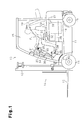
Fig. 1 is a side view showing a forklift; -
Fig. 2 is a block diagram showing the electric structure of the forklift ofFig. 1 ; -
Fig. 3 is a flowchart showing the operation of a forklift in a first embodiment; and -
Fig. 4 is a flowchart showing the operation of a forklift in a second embodiment. - A first embodiment will now be described referring to the drawings.
- As shown in
Fig. 1 , aforklift 10, which is an industrial vehicle, includes avehicle body 11 and amaterial handling device 14 located in front of thevehicle body 11. Thematerial handling device 14 includes amast 12 and afork 13. The central section of thevehicle body 11 includes anoperator cab 15. The lower front section of thevehicle body 11 includes drive wheels (front wheels) 16. The lower rear section of thevehicle body 11 includes steeredwheels 17. Thedrive wheels 16 are coupled to anengine 18 through a transmission (not shown). Theengine 18 is installed in thevehicle body 11. Theforklift 10 of the present embodiment is an engine forklift powered by theengine 18, which rotates thedrive wheels 16. A vehicle speed sensor S1 for detecting the vehicle speed of theforklift 10 is arranged at a position corresponding to thedrive wheels 16. The vehicle speed sensor S1 outputs a detection signal in accordance with the vehicle speed. - The
operator cab 15 includes anoperator seat 19 on which an operator P who operates theforklift 10 sits. Theoperator seat 19 includes a seating sensor (switch) S2. The seating sensor S2 detects whether or not the operator P is taking a driving position and seated on theoperator seat 19. The seating sensor S2 outputs the detection results as detection signals. - A
steering wheel column 20 is arranged in front of theoperator seat 19 in theoperator cab 15. Thesteering wheel column 20 is coupled to asteering wheel 21. Thesteering wheel 21 is operated to change the angle of the steeredwheels 17. - The
steering wheel column 20 includes a start switch key (not shown), which starts and stops theengine 18, and a key sensor S3, which detects the operation position of the start switch key and outputs the detection results as detection signals. - The
steering wheel column 20 also includes ashift lever 22 that instructs the driving direction of theforklift 10. Theshift lever 22 is used to select and instruct forward and backward driving directions. Further, thesteering wheel column 20 includes material handling levers 23, which include a lift lever and a tilt lever. The lift lever is operated to lift and lower thefork 13. The tilt lever is operated to tilt the entirematerial handling device 14 forward and rearward. When theforklift 10 handles a material, thematerial handling levers 23 are operated to operate thematerial handling device 14. Thesteering wheel column 20 also includes a material handling detection sensor S4 that detects operations of the material handling levers 23 and outputs a corresponding detection signal. - An
accelerator pedal 24 is arranged in front of a lower portion of theoperator seat 19. Theaccelerator pedal 24 is used to instruct acceleration (driving) of theforklift 10 and adjusts the driving speed. Thevehicle body 11 includes an accelerator depression amount sensor S5 that detects the depression amount of theaccelerator pedal 24, or the accelerator depression amount, and outputs a corresponding detection signal. - An
engine starting battery 25 is installed in thevehicle body 11. The power of theengine starting battery 25 drives the starter motor of theengine 18 and injects fuel to start theengine 18. - The
vehicle body 11 includes a hood (engine hood) 26 extending in the horizontal direction. The hood 26 is supported to be pivotal about its rear end so that the hood 26 can open and close. The hood 26 opens by pivoting to the position indicated by the double-dashed lines inFig. 1 . When the hood 26 is closed, theengine 18 and theengine starting battery 25 are located under the hood 26, and theoperator seat 19 is located above the hood 26. When the hood 26 is open, the positive and negative terminals on the upper side of theengine starting battery 25 are exposed. Theengine 18 may be started by connecting the exposed positive and negative terminals to a battery of other vehicle, for example. - In addition, the
vehicle body 11 includes avehicle controller 27, which is mainly formed by a microprocessor 27a (Fig. 2 ). Thevehicle controller 27 is activated by turning the start switch key to an on position. - As shown in
Fig. 2 , thevehicle controller 27 is electrically connected to the vehicle speed sensor S1, the seating sensor S2, the key sensor S3, the material handling detection sensor S4, and the accelerator depression amount sensor S5. Thevehicle controller 27 receives a vehicle speed signal from the vehicle speed sensor S1, a seating signal from the seating sensor S2, a key operation detection signal from the key sensor S3, a material handling detection signal from the material handling detection sensor S4, and an accelerator depression amount detection signals from the accelerator depression amount sensor S5. - Based on the detection signals received from the sensors S1 to S5, the microprocessor 27a of the
vehicle controller 27 detects the vehicle speed, the seating of the operator P on theoperator seat 19, the position of the start switch key, material handling, and the accelerator depression amount. Thevehicle controller 27 is connected to anengine controller 28, and the microprocessor 27a controls theengine 18 with theengine controller 28 based on the detection signals received from the sensors S1 to S5. - The
forklift 10 has a function to automatically stop the engine 18 (automatic engine stop function). The microprocessor 27a of thevehicle controller 27 is configured to automatically stop theengine 18. - The operation of the
forklift 10 will now be described. - As shown in
Fig. 3 , when the start switch key is at the on position and thevehicle controller 27 is activated, the microprocessor 27a determines instep 100 whether or not theengine 18 has been started when the operator P is seated on theoperator seat 19 and the seating sensor S2 is activated. If the microprocessor 27a determines that theengine 18 has been started when the operator P is seated on theoperator seat 19 and the seating sensor S2 is activated, the microprocessor 27a proceeds to step 101. Instep 101, when a predetermined condition is satisfied, for example, when the vehicle speed is null, the microprocessor 27a enables the automatic engine stop function that automatically stops theengine 18. Thus, the microprocessor 27a automatically stops theengine 18 when a predetermined time elapses from when the operator P leaves theoperator seat 19, for example. - In
step 100, if the microprocessor 27a determines that theengine 18 has been started when the operator P is not seated on theoperator seat 19 and the seating sensor S2 is deactivated, the microprocessor 27a proceeds to step 102. Instep 102, the microprocessor 27a disables the automatic engine stop function. In other words, if theengine 18 is started when the seating sensor S2 detects that the operator P is not seated on theoperator seat 19, the automatic engine stop function is disabled. Accordingly, when theengine 18 is jump-started due to drainage of theengine starting battery 25, the automatic engine stop function is disabled. This allows for the charging of theengine starting battery 25 by theengine 18. - More specifically, when the
engine starting battery 25 is drained, the battery of another vehicle or a dedicated device is connected to theengine starting battery 25 to jump-start theengine 18. In this case, theengine 18 needs to remain running even when the operator P is not seated on theoperator seat 19. In theforklift 10, theengine starting battery 25 is arranged under the engine hood 26 (under the operator seat 19). Thus, when jump-starting theengine 18, the operator P is not seated on theoperator seat 19. In a conventional forklift in which the automatic engine stop function is not disabled, if the engine is automatically stopped after a short time, the engine may be stopped before the operator sits on the operator seat after disconnecting the battery of another vehicle or the dedicated device. - In the
forklift 10 of the present embodiment, if theengine 18 is started when theoperator seat 19 is vacant, such as when theengine 18 is jump-started, the automatic engine stop function is disabled and theengine 18 is not automatically stopped while theengine starting battery 25 is being charged. Accordingly, theengine 18 continues to run and allows for the charging of theengine starting battery 25. During normal operations, when the operator P leaves theoperator seat 19, the automatic engine stop function is enabled to automatically stop theengine 18. - The advantages of the present embodiment will now be described. (1) The
forklift 10 includes the seating sensor S2, which functions as a seating detector, and the microprocessor 27a, which functions as a controller. The seating sensor S2 detects whether or not theoperator seat 19 is vacant. If theengine 18 is started when theoperator seat 19 is detected as being vacant, the microprocessor 27a disables the automatic engine stop function. Thus, when theengine 18 is jump-started due to drainage of theengine starting battery 25, the automatic engine stop function is disabled. This allows for the charging of theengine starting battery 25. Accordingly, theengine 18 may continue to run even when the operator P is not seated on theoperator seat 19, such as when theengine 18 is jump-started due to drainage of theengine starting battery 25. - A second embodiment will now be described focusing on the differences from the first embodiment.
- As shown in
Fig. 1 , theforklift 10 of the present embodiment includes a hood sensor (switch) S6 that detects opening and closing of the hood (engine hood) 26 and sends a corresponding detection signals to the vehicle controller 27 (Fig. 2 ). - As shown in
Fig. 4 , when the start key switch is at the on position and thevehicle controller 27 is activated, the microprocessor 27a determines instep 200 whether or not theengine 18 has been started when the hood 26 is open and the hood sensor S6 is deactivated. If the microprocessor 27a determines that theengine 18 has been started when the hood 26 is closed and the hood sensor S6 is activated, the microprocessor 27a proceeds to step 201. Instep 201, when a predetermined condition is satisfied, such as the vehicle speed being null, the microprocessor 27a enables the automatic engine stop function that automatically stops theengine 18. Thus, the microprocessor 27a automatically stops theengine 18 if a predetermined time elapses from when the operator P leaves theoperator seat 19, for example. - In
step 200, if the microprocessor 27a determines that theengine 18 has been started when the hood 26 is open and the hood sensor S6 is deactivated, the microprocessor 27a proceeds to step 202. Instep 202, the microprocessor 27a disables the automatic engine stop function. In other words, the automatic engine stop function is disabled when theengine 18 is started when the hood sensor S6 detects that the hood 26 is open and theoperator seat 19 is vacant. This overcomes a problem that occurs when theengine starting battery 25 is drained and theengine 18 is jump-started by connecting the battery of another vehicle. The disablement of the automatic engine stop function prevents automatic stopping of theengine 18 while theengine starting battery 25 is being charged. This allows for the charging of theengine starting battery 25 by theengine 18. - As described above, the automatic engine stop function is enabled or disabled based on the detection of the opening and closing of the hood 26. Further, the
forklift 10 may include an engine start interlock system that prevents theengine 18 from starting unless the brake pedal or the clutch pedal is depressed when the hood 26 is closed. In this case, when the hood 26 is open, the automatic engine stop function can be disabled and theengine 18 can be started even when the brake pedal or the clutch pedal is not depressed. - Accordingly, the second embodiment has the following advantage in addition to advantage (1) of the first embodiment.
- (2) When the hood 26, which is supported by the
vehicle body 11 to be able to open and close, is closed, theengine starting battery 25 is located under the hood 26 and theoperator seat 19 is located above the hood 26. The hood sensor S6 and the microprocessor 27a, which function as seating detectors, determine whether or not theoperator seat 19 is vacant based on the opening and closing of the hood 26. When the hood 26 is open, the microprocessor 27a determines that theoperator seat 19 is vacant. If theengine 18 is started when theoperator seat 19 is determined to be vacant, the microprocessor 27a disables the engine automatic stop function. - It should be apparent to those skilled in the art that the present invention may be embodied in many other specific forms without departing from the spirit or scope of the invention. Particularly, it should be understood that the present invention may be embodied in the following form.
- The industrial vehicle is not limited to a forklift.
- The present examples and embodiments are to be considered as illustrative and not restrictive and the invention is not to be limited to the details given herein, but may be modified within the scope and equivalence of the appended claims.
- An industrial vehicle implements an automatic engine stop function that automatically stops an engine installed on a vehicle body. The industrial vehicle includes an engine starting battery arranged in the vehicle body to start the engine, an operator seat arranged on the vehicle body, a seating detector adapted to detect whether or not the operator seat is vacant, and a controller adapted to disable the automatic engine stop function if the engine is started when the seating detector detects that the operator seat is vacant.
Claims (4)
- An industrial vehicle (10) that implements an automatic engine stop function that automatically stops an engine (18) installed on a vehicle body (11), the industrial vehicle (10) comprising:an engine starting battery (25) arranged in the vehicle body (11) to start the engine (18); andan operator seat (19) arranged on the vehicle body (11),the industrial vehicle (10) being characterized bya seating detector (S2, S6, 27a) adapted to detect whether or not the operator seat (19) is vacant, anda controller (27a) adapted to disable the automatic engine stop function if the engine (18) is started when the seating detector (S2, S6, 27a) detects that the operator seat (19) is vacant.
- The industrial vehicle (10) according to claim 1, further comprising a hood (26) supported by the vehicle body (11) to be able to open and close, wherein
when the hood (26) is closed, the engine starting battery (25) is located under the hood (26) and the operator seat (19) is located above the hood (26), and
the seating detector (S6, 27a) is adapted to detect whether or not the operator seat (19) is vacant based on the opening and closing of the hood (26). - The industrial vehicle according to claim 1 or 2, wherein the industrial vehicle (10) is a forklift (10).
- A method for controlling an industrial vehicle (10) including a vehicle body (11), an engine (18), an engine starting battery (25) for starting the engine (18), and an operator seat (19), wherein the industrial vehicle (10) implements an automatic engine stop function that automatically stops the engine (18), the method comprising:determining whether or not the operator seat (19) is vacant when the engine (18) is started; anddisabling the automatic engine stop function when determining that the operator seat (19) is vacant when the engine (18) is started.
Applications Claiming Priority (1)
| Application Number | Priority Date | Filing Date | Title |
|---|---|---|---|
| JP2013139692A JP5831504B2 (en) | 2013-07-03 | 2013-07-03 | Industrial vehicle |
Publications (2)
| Publication Number | Publication Date |
|---|---|
| EP2915690A1 true EP2915690A1 (en) | 2015-09-09 |
| EP2915690B1 EP2915690B1 (en) | 2016-11-02 |
Family
ID=51205168
Family Applications (1)
| Application Number | Title | Priority Date | Filing Date |
|---|---|---|---|
| EP14174072.0A Active EP2915690B1 (en) | 2013-07-03 | 2014-06-26 | Industrial vehicle and method for controlling industrial vehicle |
Country Status (6)
| Country | Link |
|---|---|
| US (1) | US9340109B2 (en) |
| EP (1) | EP2915690B1 (en) |
| JP (1) | JP5831504B2 (en) |
| CN (1) | CN104279062B (en) |
| AU (1) | AU2014203351B2 (en) |
| CA (1) | CA2855012C (en) |
Families Citing this family (3)
| Publication number | Priority date | Publication date | Assignee | Title |
|---|---|---|---|---|
| JP6713633B2 (en) * | 2016-12-05 | 2020-06-24 | ヤンマーパワーテクノロジー株式会社 | Tractor |
| JP7338334B2 (en) * | 2019-09-04 | 2023-09-05 | 株式会社豊田自動織機 | Industrial vehicle engine controller |
| US12366096B2 (en) | 2023-08-29 | 2025-07-22 | Toyota Motor Engineering & Manufacturing North America, Inc. | Operation logic for a power hood system |
Citations (4)
| Publication number | Priority date | Publication date | Assignee | Title |
|---|---|---|---|---|
| US4509614A (en) * | 1982-12-13 | 1985-04-09 | Kubota Ltd. | Working vehicle equipped with engine automatic stop device |
| JPH01155037A (en) * | 1987-12-10 | 1989-06-16 | Honda Motor Co Ltd | Work vehicle operation control device |
| US20040026150A1 (en) * | 2002-08-06 | 2004-02-12 | Kubota Corporation | Work vehicle having overridable automatic engine stop circuit |
| JP2004132249A (en) | 2002-10-10 | 2004-04-30 | Nissan Motor Co Ltd | Engine automatic stop / start system for industrial vehicles |
Family Cites Families (14)
| Publication number | Priority date | Publication date | Assignee | Title |
|---|---|---|---|---|
| US4116296A (en) * | 1977-03-09 | 1978-09-26 | Eaton Corporation | Automatic seat brake |
| US5156232A (en) * | 1989-04-13 | 1992-10-20 | Fumio Muroya | Operation controlling apparatus of the passenger working machine |
| US5203440A (en) * | 1992-06-24 | 1993-04-20 | Deere & Company | Interlock circuit for a vehicle with an optical second drive |
| JP4085675B2 (en) * | 2002-04-01 | 2008-05-14 | 株式会社豊田自動織機 | Industrial vehicle |
| JP4123964B2 (en) * | 2003-02-17 | 2008-07-23 | コベルコ建機株式会社 | Engine control device for construction machinery |
| JP4552499B2 (en) * | 2004-05-06 | 2010-09-29 | 株式会社豊田自動織機 | Abnormality confirmation method and apparatus for presence detection means in industrial vehicles |
| FR2874659B1 (en) * | 2004-08-27 | 2011-03-18 | Peugeot Citroen Automobiles Sa | METHOD FOR INHIBITING THE AUTOMATIC STOP CONTROL OF THE THERMAL MOTOR OF A VEHICLE IN CASE OF ABSENCE OF THE DRIVER |
| DE102007009870B4 (en) * | 2007-02-28 | 2018-05-17 | Bayerische Motoren Werke Aktiengesellschaft | Method for controlling an automatic switch-off operation and / or switch-on operation of an internal combustion engine in a motor vehicle |
| DE102007009871A1 (en) * | 2007-02-28 | 2008-09-04 | Bayerische Motoren Werke Aktiengesellschaft | Method for controlling automatic switching off process for internal combustion engine in motor vehicle, involves preventing automatic switching off of internal combustion engine in dependence of given operating conditions |
| JP2011017271A (en) * | 2009-07-08 | 2011-01-27 | Yanmar Co Ltd | Engine control device for working vehicle |
| KR101199058B1 (en) * | 2010-12-06 | 2012-11-07 | 기아자동차주식회사 | Idle stop and go system and method for controlling thereof |
| WO2012137582A1 (en) * | 2011-04-08 | 2012-10-11 | 株式会社小松製作所 | Battery-operated forklift |
| DE102011107005B4 (en) | 2011-07-09 | 2014-10-16 | Audi Ag | Method for operating a motor vehicle with automatic engine shutdown |
| CN202338404U (en) * | 2011-10-27 | 2012-07-18 | 上海市宝山区青少年科学技术指导站 | Idling blanker |
-
2013
- 2013-07-03 JP JP2013139692A patent/JP5831504B2/en active Active
-
2014
- 2014-06-19 CA CA2855012A patent/CA2855012C/en active Active
- 2014-06-20 AU AU2014203351A patent/AU2014203351B2/en active Active
- 2014-06-26 EP EP14174072.0A patent/EP2915690B1/en active Active
- 2014-06-30 US US14/319,780 patent/US9340109B2/en active Active
- 2014-07-01 CN CN201410311176.9A patent/CN104279062B/en active Active
Patent Citations (4)
| Publication number | Priority date | Publication date | Assignee | Title |
|---|---|---|---|---|
| US4509614A (en) * | 1982-12-13 | 1985-04-09 | Kubota Ltd. | Working vehicle equipped with engine automatic stop device |
| JPH01155037A (en) * | 1987-12-10 | 1989-06-16 | Honda Motor Co Ltd | Work vehicle operation control device |
| US20040026150A1 (en) * | 2002-08-06 | 2004-02-12 | Kubota Corporation | Work vehicle having overridable automatic engine stop circuit |
| JP2004132249A (en) | 2002-10-10 | 2004-04-30 | Nissan Motor Co Ltd | Engine automatic stop / start system for industrial vehicles |
Also Published As
| Publication number | Publication date |
|---|---|
| AU2014203351A1 (en) | 2015-01-22 |
| CN104279062A (en) | 2015-01-14 |
| US9340109B2 (en) | 2016-05-17 |
| AU2014203351B2 (en) | 2016-06-09 |
| CN104279062B (en) | 2017-01-04 |
| CA2855012C (en) | 2016-07-26 |
| EP2915690B1 (en) | 2016-11-02 |
| US20150012187A1 (en) | 2015-01-08 |
| JP5831504B2 (en) | 2015-12-09 |
| CA2855012A1 (en) | 2015-01-03 |
| JP2015014205A (en) | 2015-01-22 |
Similar Documents
| Publication | Publication Date | Title |
|---|---|---|
| CN102602302B (en) | Control device for electric vehicle | |
| US8880260B2 (en) | Control device for use in vehicle, adapted to control safety measures against electric power supply failure | |
| US7725246B2 (en) | Method and start control device for controlling an automatic start-up process of a drive unit | |
| EP2915690B1 (en) | Industrial vehicle and method for controlling industrial vehicle | |
| JP2013233893A (en) | Running control device | |
| US12258106B2 (en) | Tetherless shutoff systems and methods for powersport vehicles | |
| JP3861068B2 (en) | Automatic parking equipment | |
| JP6167387B2 (en) | Hybrid work vehicle | |
| US7240757B2 (en) | Control system of self propelled industrial machine | |
| JP2010143542A (en) | Electric parking brake system | |
| KR101413253B1 (en) | Engine stop control system and control methods of agriculture vehicle | |
| JP2021032101A (en) | Quick start prevention device of vehicle | |
| TWI822660B (en) | Parking assist system for a two-wheeled vehicle & a control method thereof | |
| CN120569316A (en) | Work vehicles | |
| CA3202817A1 (en) | Off-throttle steering for jet propulsion watercraft | |
| KR102251665B1 (en) | Selection Switch System Of ISG Function For Motorcycle, And Control Method For The Same | |
| JP7715480B2 (en) | Forklift and interlock unauthorized release prevention method | |
| JP2019033635A (en) | Electric vehicle | |
| EP3219976B1 (en) | Saddle-riding type vehicle | |
| KR20220042205A (en) | Engine Control Units of Industrial Vehicles | |
| JP5273684B2 (en) | Electric vehicle travel control device and electric vehicle | |
| WO2022018738A1 (en) | A throttle interlock system for a vehicle | |
| JP5309794B2 (en) | Cargo handling vehicle | |
| WO2018167703A1 (en) | A method for activating and deactivating a vehicle | |
| JP2004175220A (en) | Engine control device |
Legal Events
| Date | Code | Title | Description |
|---|---|---|---|
| PUAI | Public reference made under article 153(3) epc to a published international application that has entered the european phase |
Free format text: ORIGINAL CODE: 0009012 |
|
| 17P | Request for examination filed |
Effective date: 20140626 |
|
| AK | Designated contracting states |
Kind code of ref document: A1 Designated state(s): AL AT BE BG CH CY CZ DE DK EE ES FI FR GB GR HR HU IE IS IT LI LT LU LV MC MK MT NL NO PL PT RO RS SE SI SK SM TR |
|
| AX | Request for extension of the european patent |
Extension state: BA ME |
|
| RIC1 | Information provided on ipc code assigned before grant |
Ipc: B60K 28/10 20060101ALI20160129BHEP Ipc: B60N 2/02 20060101ALI20160129BHEP Ipc: B60K 28/04 20060101AFI20160129BHEP Ipc: B60K 25/00 20060101ALI20160129BHEP |
|
| GRAP | Despatch of communication of intention to grant a patent |
Free format text: ORIGINAL CODE: EPIDOSNIGR1 |
|
| INTG | Intention to grant announced |
Effective date: 20160610 |
|
| RIN1 | Information on inventor provided before grant (corrected) |
Inventor name: KATO, NORIHIKO Inventor name: KOIDE, YUKIKAZU |
|
| GRAS | Grant fee paid |
Free format text: ORIGINAL CODE: EPIDOSNIGR3 |
|
| GRAA | (expected) grant |
Free format text: ORIGINAL CODE: 0009210 |
|
| AK | Designated contracting states |
Kind code of ref document: B1 Designated state(s): AL AT BE BG CH CY CZ DE DK EE ES FI FR GB GR HR HU IE IS IT LI LT LU LV MC MK MT NL NO PL PT RO RS SE SI SK SM TR |
|
| REG | Reference to a national code |
Ref country code: GB Ref legal event code: FG4D |
|
| REG | Reference to a national code |
Ref country code: AT Ref legal event code: REF Ref document number: 841465 Country of ref document: AT Kind code of ref document: T Effective date: 20161115 Ref country code: CH Ref legal event code: EP |
|
| REG | Reference to a national code |
Ref country code: IE Ref legal event code: FG4D |
|
| REG | Reference to a national code |
Ref country code: DE Ref legal event code: R096 Ref document number: 602014004572 Country of ref document: DE |
|
| PG25 | Lapsed in a contracting state [announced via postgrant information from national office to epo] |
Ref country code: LV Free format text: LAPSE BECAUSE OF FAILURE TO SUBMIT A TRANSLATION OF THE DESCRIPTION OR TO PAY THE FEE WITHIN THE PRESCRIBED TIME-LIMIT Effective date: 20161102 |
|
| REG | Reference to a national code |
Ref country code: NL Ref legal event code: MP Effective date: 20161102 |
|
| REG | Reference to a national code |
Ref country code: LT Ref legal event code: MG4D |
|
| REG | Reference to a national code |
Ref country code: AT Ref legal event code: MK05 Ref document number: 841465 Country of ref document: AT Kind code of ref document: T Effective date: 20161102 |
|
| PG25 | Lapsed in a contracting state [announced via postgrant information from national office to epo] |
Ref country code: NO Free format text: LAPSE BECAUSE OF FAILURE TO SUBMIT A TRANSLATION OF THE DESCRIPTION OR TO PAY THE FEE WITHIN THE PRESCRIBED TIME-LIMIT Effective date: 20170202 Ref country code: LT Free format text: LAPSE BECAUSE OF FAILURE TO SUBMIT A TRANSLATION OF THE DESCRIPTION OR TO PAY THE FEE WITHIN THE PRESCRIBED TIME-LIMIT Effective date: 20161102 Ref country code: NL Free format text: LAPSE BECAUSE OF FAILURE TO SUBMIT A TRANSLATION OF THE DESCRIPTION OR TO PAY THE FEE WITHIN THE PRESCRIBED TIME-LIMIT Effective date: 20161102 Ref country code: SE Free format text: LAPSE BECAUSE OF FAILURE TO SUBMIT A TRANSLATION OF THE DESCRIPTION OR TO PAY THE FEE WITHIN THE PRESCRIBED TIME-LIMIT Effective date: 20161102 Ref country code: GR Free format text: LAPSE BECAUSE OF FAILURE TO SUBMIT A TRANSLATION OF THE DESCRIPTION OR TO PAY THE FEE WITHIN THE PRESCRIBED TIME-LIMIT Effective date: 20170203 |
|
| PG25 | Lapsed in a contracting state [announced via postgrant information from national office to epo] |
Ref country code: AT Free format text: LAPSE BECAUSE OF FAILURE TO SUBMIT A TRANSLATION OF THE DESCRIPTION OR TO PAY THE FEE WITHIN THE PRESCRIBED TIME-LIMIT Effective date: 20161102 Ref country code: HR Free format text: LAPSE BECAUSE OF FAILURE TO SUBMIT A TRANSLATION OF THE DESCRIPTION OR TO PAY THE FEE WITHIN THE PRESCRIBED TIME-LIMIT Effective date: 20161102 Ref country code: IS Free format text: LAPSE BECAUSE OF FAILURE TO SUBMIT A TRANSLATION OF THE DESCRIPTION OR TO PAY THE FEE WITHIN THE PRESCRIBED TIME-LIMIT Effective date: 20170302 Ref country code: RS Free format text: LAPSE BECAUSE OF FAILURE TO SUBMIT A TRANSLATION OF THE DESCRIPTION OR TO PAY THE FEE WITHIN THE PRESCRIBED TIME-LIMIT Effective date: 20161102 Ref country code: PL Free format text: LAPSE BECAUSE OF FAILURE TO SUBMIT A TRANSLATION OF THE DESCRIPTION OR TO PAY THE FEE WITHIN THE PRESCRIBED TIME-LIMIT Effective date: 20161102 Ref country code: FI Free format text: LAPSE BECAUSE OF FAILURE TO SUBMIT A TRANSLATION OF THE DESCRIPTION OR TO PAY THE FEE WITHIN THE PRESCRIBED TIME-LIMIT Effective date: 20161102 Ref country code: PT Free format text: LAPSE BECAUSE OF FAILURE TO SUBMIT A TRANSLATION OF THE DESCRIPTION OR TO PAY THE FEE WITHIN THE PRESCRIBED TIME-LIMIT Effective date: 20170302 Ref country code: ES Free format text: LAPSE BECAUSE OF FAILURE TO SUBMIT A TRANSLATION OF THE DESCRIPTION OR TO PAY THE FEE WITHIN THE PRESCRIBED TIME-LIMIT Effective date: 20161102 |
|
| REG | Reference to a national code |
Ref country code: FR Ref legal event code: PLFP Year of fee payment: 4 |
|
| PG25 | Lapsed in a contracting state [announced via postgrant information from national office to epo] |
Ref country code: EE Free format text: LAPSE BECAUSE OF FAILURE TO SUBMIT A TRANSLATION OF THE DESCRIPTION OR TO PAY THE FEE WITHIN THE PRESCRIBED TIME-LIMIT Effective date: 20161102 Ref country code: CZ Free format text: LAPSE BECAUSE OF FAILURE TO SUBMIT A TRANSLATION OF THE DESCRIPTION OR TO PAY THE FEE WITHIN THE PRESCRIBED TIME-LIMIT Effective date: 20161102 Ref country code: DK Free format text: LAPSE BECAUSE OF FAILURE TO SUBMIT A TRANSLATION OF THE DESCRIPTION OR TO PAY THE FEE WITHIN THE PRESCRIBED TIME-LIMIT Effective date: 20161102 Ref country code: RO Free format text: LAPSE BECAUSE OF FAILURE TO SUBMIT A TRANSLATION OF THE DESCRIPTION OR TO PAY THE FEE WITHIN THE PRESCRIBED TIME-LIMIT Effective date: 20161102 Ref country code: SK Free format text: LAPSE BECAUSE OF FAILURE TO SUBMIT A TRANSLATION OF THE DESCRIPTION OR TO PAY THE FEE WITHIN THE PRESCRIBED TIME-LIMIT Effective date: 20161102 |
|
| REG | Reference to a national code |
Ref country code: DE Ref legal event code: R097 Ref document number: 602014004572 Country of ref document: DE |
|
| PG25 | Lapsed in a contracting state [announced via postgrant information from national office to epo] |
Ref country code: BE Free format text: LAPSE BECAUSE OF FAILURE TO SUBMIT A TRANSLATION OF THE DESCRIPTION OR TO PAY THE FEE WITHIN THE PRESCRIBED TIME-LIMIT Effective date: 20161102 Ref country code: BG Free format text: LAPSE BECAUSE OF FAILURE TO SUBMIT A TRANSLATION OF THE DESCRIPTION OR TO PAY THE FEE WITHIN THE PRESCRIBED TIME-LIMIT Effective date: 20170202 Ref country code: IT Free format text: LAPSE BECAUSE OF FAILURE TO SUBMIT A TRANSLATION OF THE DESCRIPTION OR TO PAY THE FEE WITHIN THE PRESCRIBED TIME-LIMIT Effective date: 20161102 Ref country code: SM Free format text: LAPSE BECAUSE OF FAILURE TO SUBMIT A TRANSLATION OF THE DESCRIPTION OR TO PAY THE FEE WITHIN THE PRESCRIBED TIME-LIMIT Effective date: 20161102 |
|
| PLBE | No opposition filed within time limit |
Free format text: ORIGINAL CODE: 0009261 |
|
| STAA | Information on the status of an ep patent application or granted ep patent |
Free format text: STATUS: NO OPPOSITION FILED WITHIN TIME LIMIT |
|
| 26N | No opposition filed |
Effective date: 20170803 |
|
| PG25 | Lapsed in a contracting state [announced via postgrant information from national office to epo] |
Ref country code: SI Free format text: LAPSE BECAUSE OF FAILURE TO SUBMIT A TRANSLATION OF THE DESCRIPTION OR TO PAY THE FEE WITHIN THE PRESCRIBED TIME-LIMIT Effective date: 20161102 |
|
| PG25 | Lapsed in a contracting state [announced via postgrant information from national office to epo] |
Ref country code: MC Free format text: LAPSE BECAUSE OF FAILURE TO SUBMIT A TRANSLATION OF THE DESCRIPTION OR TO PAY THE FEE WITHIN THE PRESCRIBED TIME-LIMIT Effective date: 20161102 |
|
| REG | Reference to a national code |
Ref country code: CH Ref legal event code: PL |
|
| REG | Reference to a national code |
Ref country code: IE Ref legal event code: MM4A |
|
| PG25 | Lapsed in a contracting state [announced via postgrant information from national office to epo] |
Ref country code: IE Free format text: LAPSE BECAUSE OF NON-PAYMENT OF DUE FEES Effective date: 20170626 Ref country code: CH Free format text: LAPSE BECAUSE OF NON-PAYMENT OF DUE FEES Effective date: 20170630 Ref country code: LI Free format text: LAPSE BECAUSE OF NON-PAYMENT OF DUE FEES Effective date: 20170630 Ref country code: LU Free format text: LAPSE BECAUSE OF NON-PAYMENT OF DUE FEES Effective date: 20170626 |
|
| REG | Reference to a national code |
Ref country code: FR Ref legal event code: PLFP Year of fee payment: 5 |
|
| PG25 | Lapsed in a contracting state [announced via postgrant information from national office to epo] |
Ref country code: MT Free format text: LAPSE BECAUSE OF NON-PAYMENT OF DUE FEES Effective date: 20170626 |
|
| PG25 | Lapsed in a contracting state [announced via postgrant information from national office to epo] |
Ref country code: HU Free format text: LAPSE BECAUSE OF FAILURE TO SUBMIT A TRANSLATION OF THE DESCRIPTION OR TO PAY THE FEE WITHIN THE PRESCRIBED TIME-LIMIT; INVALID AB INITIO Effective date: 20140626 |
|
| PG25 | Lapsed in a contracting state [announced via postgrant information from national office to epo] |
Ref country code: CY Free format text: LAPSE BECAUSE OF FAILURE TO SUBMIT A TRANSLATION OF THE DESCRIPTION OR TO PAY THE FEE WITHIN THE PRESCRIBED TIME-LIMIT Effective date: 20161102 |
|
| PG25 | Lapsed in a contracting state [announced via postgrant information from national office to epo] |
Ref country code: MK Free format text: LAPSE BECAUSE OF FAILURE TO SUBMIT A TRANSLATION OF THE DESCRIPTION OR TO PAY THE FEE WITHIN THE PRESCRIBED TIME-LIMIT Effective date: 20161102 |
|
| PG25 | Lapsed in a contracting state [announced via postgrant information from national office to epo] |
Ref country code: TR Free format text: LAPSE BECAUSE OF FAILURE TO SUBMIT A TRANSLATION OF THE DESCRIPTION OR TO PAY THE FEE WITHIN THE PRESCRIBED TIME-LIMIT Effective date: 20161102 |
|
| PG25 | Lapsed in a contracting state [announced via postgrant information from national office to epo] |
Ref country code: AL Free format text: LAPSE BECAUSE OF FAILURE TO SUBMIT A TRANSLATION OF THE DESCRIPTION OR TO PAY THE FEE WITHIN THE PRESCRIBED TIME-LIMIT Effective date: 20161102 |
|
| P01 | Opt-out of the competence of the unified patent court (upc) registered |
Effective date: 20230519 |
|
| PGFP | Annual fee paid to national office [announced via postgrant information from national office to epo] |
Ref country code: DE Payment date: 20250429 Year of fee payment: 12 |
|
| PGFP | Annual fee paid to national office [announced via postgrant information from national office to epo] |
Ref country code: GB Payment date: 20250508 Year of fee payment: 12 |
|
| PGFP | Annual fee paid to national office [announced via postgrant information from national office to epo] |
Ref country code: FR Payment date: 20250508 Year of fee payment: 12 |