EP2915512A1 - Disposable diaper production method and production device - Google Patents
Disposable diaper production method and production device Download PDFInfo
- Publication number
- EP2915512A1 EP2915512A1 EP13863778.0A EP13863778A EP2915512A1 EP 2915512 A1 EP2915512 A1 EP 2915512A1 EP 13863778 A EP13863778 A EP 13863778A EP 2915512 A1 EP2915512 A1 EP 2915512A1
- Authority
- EP
- European Patent Office
- Prior art keywords
- portions
- unit
- side pieces
- disposable diaper
- conveying
- Prior art date
- Legal status (The legal status is an assumption and is not a legal conclusion. Google has not performed a legal analysis and makes no representation as to the accuracy of the status listed.)
- Granted
Links
Images


Classifications
-
- A—HUMAN NECESSITIES
- A61—MEDICAL OR VETERINARY SCIENCE; HYGIENE
- A61F—FILTERS IMPLANTABLE INTO BLOOD VESSELS; PROSTHESES; DEVICES PROVIDING PATENCY TO, OR PREVENTING COLLAPSING OF, TUBULAR STRUCTURES OF THE BODY, e.g. STENTS; ORTHOPAEDIC, NURSING OR CONTRACEPTIVE DEVICES; FOMENTATION; TREATMENT OR PROTECTION OF EYES OR EARS; BANDAGES, DRESSINGS OR ABSORBENT PADS; FIRST-AID KITS
- A61F13/00—Bandages or dressings; Absorbent pads
- A61F13/15—Absorbent pads, e.g. sanitary towels, swabs or tampons for external or internal application to the body; Supporting or fastening means therefor; Tampon applicators
- A61F13/15577—Apparatus or processes for manufacturing
- A61F13/15585—Apparatus or processes for manufacturing of babies' napkins, e.g. diapers
-
- A—HUMAN NECESSITIES
- A61—MEDICAL OR VETERINARY SCIENCE; HYGIENE
- A61F—FILTERS IMPLANTABLE INTO BLOOD VESSELS; PROSTHESES; DEVICES PROVIDING PATENCY TO, OR PREVENTING COLLAPSING OF, TUBULAR STRUCTURES OF THE BODY, e.g. STENTS; ORTHOPAEDIC, NURSING OR CONTRACEPTIVE DEVICES; FOMENTATION; TREATMENT OR PROTECTION OF EYES OR EARS; BANDAGES, DRESSINGS OR ABSORBENT PADS; FIRST-AID KITS
- A61F13/00—Bandages or dressings; Absorbent pads
- A61F13/15—Absorbent pads, e.g. sanitary towels, swabs or tampons for external or internal application to the body; Supporting or fastening means therefor; Tampon applicators
-
- A—HUMAN NECESSITIES
- A61—MEDICAL OR VETERINARY SCIENCE; HYGIENE
- A61F—FILTERS IMPLANTABLE INTO BLOOD VESSELS; PROSTHESES; DEVICES PROVIDING PATENCY TO, OR PREVENTING COLLAPSING OF, TUBULAR STRUCTURES OF THE BODY, e.g. STENTS; ORTHOPAEDIC, NURSING OR CONTRACEPTIVE DEVICES; FOMENTATION; TREATMENT OR PROTECTION OF EYES OR EARS; BANDAGES, DRESSINGS OR ABSORBENT PADS; FIRST-AID KITS
- A61F13/00—Bandages or dressings; Absorbent pads
- A61F13/15—Absorbent pads, e.g. sanitary towels, swabs or tampons for external or internal application to the body; Supporting or fastening means therefor; Tampon applicators
- A61F13/15577—Apparatus or processes for manufacturing
- A61F13/15707—Mechanical treatment, e.g. notching, twisting, compressing, shaping
- A61F13/15739—Sealing, e.g. involving cutting
-
- A—HUMAN NECESSITIES
- A61—MEDICAL OR VETERINARY SCIENCE; HYGIENE
- A61F—FILTERS IMPLANTABLE INTO BLOOD VESSELS; PROSTHESES; DEVICES PROVIDING PATENCY TO, OR PREVENTING COLLAPSING OF, TUBULAR STRUCTURES OF THE BODY, e.g. STENTS; ORTHOPAEDIC, NURSING OR CONTRACEPTIVE DEVICES; FOMENTATION; TREATMENT OR PROTECTION OF EYES OR EARS; BANDAGES, DRESSINGS OR ABSORBENT PADS; FIRST-AID KITS
- A61F13/00—Bandages or dressings; Absorbent pads
- A61F13/15—Absorbent pads, e.g. sanitary towels, swabs or tampons for external or internal application to the body; Supporting or fastening means therefor; Tampon applicators
- A61F13/15577—Apparatus or processes for manufacturing
- A61F13/15707—Mechanical treatment, e.g. notching, twisting, compressing, shaping
- A61F13/15747—Folding; Pleating; Coiling; Stacking; Packaging
-
- A—HUMAN NECESSITIES
- A61—MEDICAL OR VETERINARY SCIENCE; HYGIENE
- A61F—FILTERS IMPLANTABLE INTO BLOOD VESSELS; PROSTHESES; DEVICES PROVIDING PATENCY TO, OR PREVENTING COLLAPSING OF, TUBULAR STRUCTURES OF THE BODY, e.g. STENTS; ORTHOPAEDIC, NURSING OR CONTRACEPTIVE DEVICES; FOMENTATION; TREATMENT OR PROTECTION OF EYES OR EARS; BANDAGES, DRESSINGS OR ABSORBENT PADS; FIRST-AID KITS
- A61F13/00—Bandages or dressings; Absorbent pads
- A61F13/15—Absorbent pads, e.g. sanitary towels, swabs or tampons for external or internal application to the body; Supporting or fastening means therefor; Tampon applicators
- A61F13/15577—Apparatus or processes for manufacturing
- A61F13/15756—Applying tabs, strips, tapes, loops; Knotting the ends of pads
-
- A—HUMAN NECESSITIES
- A61—MEDICAL OR VETERINARY SCIENCE; HYGIENE
- A61F—FILTERS IMPLANTABLE INTO BLOOD VESSELS; PROSTHESES; DEVICES PROVIDING PATENCY TO, OR PREVENTING COLLAPSING OF, TUBULAR STRUCTURES OF THE BODY, e.g. STENTS; ORTHOPAEDIC, NURSING OR CONTRACEPTIVE DEVICES; FOMENTATION; TREATMENT OR PROTECTION OF EYES OR EARS; BANDAGES, DRESSINGS OR ABSORBENT PADS; FIRST-AID KITS
- A61F13/00—Bandages or dressings; Absorbent pads
- A61F13/15—Absorbent pads, e.g. sanitary towels, swabs or tampons for external or internal application to the body; Supporting or fastening means therefor; Tampon applicators
- A61F13/15577—Apparatus or processes for manufacturing
- A61F13/15764—Transferring, feeding or handling devices; Drives
-
- A—HUMAN NECESSITIES
- A61—MEDICAL OR VETERINARY SCIENCE; HYGIENE
- A61F—FILTERS IMPLANTABLE INTO BLOOD VESSELS; PROSTHESES; DEVICES PROVIDING PATENCY TO, OR PREVENTING COLLAPSING OF, TUBULAR STRUCTURES OF THE BODY, e.g. STENTS; ORTHOPAEDIC, NURSING OR CONTRACEPTIVE DEVICES; FOMENTATION; TREATMENT OR PROTECTION OF EYES OR EARS; BANDAGES, DRESSINGS OR ABSORBENT PADS; FIRST-AID KITS
- A61F13/00—Bandages or dressings; Absorbent pads
- A61F13/15—Absorbent pads, e.g. sanitary towels, swabs or tampons for external or internal application to the body; Supporting or fastening means therefor; Tampon applicators
- A61F13/45—Absorbent pads, e.g. sanitary towels, swabs or tampons for external or internal application to the body; Supporting or fastening means therefor; Tampon applicators characterised by the shape
- A61F13/49—Absorbent pads, e.g. sanitary towels, swabs or tampons for external or internal application to the body; Supporting or fastening means therefor; Tampon applicators characterised by the shape specially adapted to be worn around the waist, e.g. diapers, nappies
-
- A—HUMAN NECESSITIES
- A61—MEDICAL OR VETERINARY SCIENCE; HYGIENE
- A61F—FILTERS IMPLANTABLE INTO BLOOD VESSELS; PROSTHESES; DEVICES PROVIDING PATENCY TO, OR PREVENTING COLLAPSING OF, TUBULAR STRUCTURES OF THE BODY, e.g. STENTS; ORTHOPAEDIC, NURSING OR CONTRACEPTIVE DEVICES; FOMENTATION; TREATMENT OR PROTECTION OF EYES OR EARS; BANDAGES, DRESSINGS OR ABSORBENT PADS; FIRST-AID KITS
- A61F13/00—Bandages or dressings; Absorbent pads
- A61F13/15—Absorbent pads, e.g. sanitary towels, swabs or tampons for external or internal application to the body; Supporting or fastening means therefor; Tampon applicators
- A61F13/45—Absorbent pads, e.g. sanitary towels, swabs or tampons for external or internal application to the body; Supporting or fastening means therefor; Tampon applicators characterised by the shape
- A61F13/49—Absorbent pads, e.g. sanitary towels, swabs or tampons for external or internal application to the body; Supporting or fastening means therefor; Tampon applicators characterised by the shape specially adapted to be worn around the waist, e.g. diapers, nappies
- A61F13/496—Absorbent pads, e.g. sanitary towels, swabs or tampons for external or internal application to the body; Supporting or fastening means therefor; Tampon applicators characterised by the shape specially adapted to be worn around the waist, e.g. diapers, nappies in the form of pants or briefs
-
- A—HUMAN NECESSITIES
- A61—MEDICAL OR VETERINARY SCIENCE; HYGIENE
- A61F—FILTERS IMPLANTABLE INTO BLOOD VESSELS; PROSTHESES; DEVICES PROVIDING PATENCY TO, OR PREVENTING COLLAPSING OF, TUBULAR STRUCTURES OF THE BODY, e.g. STENTS; ORTHOPAEDIC, NURSING OR CONTRACEPTIVE DEVICES; FOMENTATION; TREATMENT OR PROTECTION OF EYES OR EARS; BANDAGES, DRESSINGS OR ABSORBENT PADS; FIRST-AID KITS
- A61F13/00—Bandages or dressings; Absorbent pads
- A61F13/15—Absorbent pads, e.g. sanitary towels, swabs or tampons for external or internal application to the body; Supporting or fastening means therefor; Tampon applicators
- A61F13/15577—Apparatus or processes for manufacturing
- A61F2013/15821—Apparatus or processes for manufacturing characterized by the apparatus for manufacturing
- A61F2013/15861—Apparatus or processes for manufacturing characterized by the apparatus for manufacturing for bonding
- A61F2013/15869—Apparatus or processes for manufacturing characterized by the apparatus for manufacturing for bonding with ultrasonic energy
Definitions
- the present invention relates to a disposable diaper production method and a disposable diaper production device for producing a disposable diaper having a main body portion that extends from a front belly part to a back part via a crotch part and a pair of side portions that covers the side surfaces of the lumbar part of a wearer when the disposable diaper is worn.
- a disposable diaper 1 as an example of disposable wearing articles is a so-called underpants-shaped diaper.
- a disposable diaper 1 has a diaper main body (main body portion) 2 that extends from the front belly part to the back part via the crotch part of a wearer and four side panel pieces (side pieces) 3 and 4 each of which protrudes from both ends in the longitudinal direction (vertical direction in Fig. 2 ) of the diaper main body 2 in the width direction (horizontal direction in Fig. 2 ) of the diaper main body 2 when the disposable diaper 1 is worn.
- the respective side panel pieces 4 extend from both end portions in the longitudinal direction of the diaper main body 2 to one side in the horizontal direction (left side in Figs. 1 and 2 ) and has elasticity in the horizontal direction.
- a gap portion 4a is formed between the respective side panel pieces 4 and used as a leg hole when the left edge portions of the respective side panel pieces 4 are bonded to each other through the side seal portions 6.
- the respective side panel pieces 4 are bonded to the sheets 10 and 11 in a state of being sandwiched between the inner sheet 10 and the outer sheet 11 on the left side of the absorber 7.
- the tentative fastening protruding portions 22b are constituted by screw portions. Therefore, the protruding amount of the tentative fastening protruding portions 22b can be adjusted in such a way as to adjust the fastening degree of the tentative fastening protruding portions 22b with respect to the fist holding plate 22. Note that although the side panel pieces 3 and 4 are compressed to form the tentative fastening portions 3c and 4c, heat may be applied to the side panel pieces 3 and 4 to form the tentative fastening portions 3c and 4c.
Landscapes
- Health & Medical Sciences (AREA)
- Engineering & Computer Science (AREA)
- Heart & Thoracic Surgery (AREA)
- Epidemiology (AREA)
- Biomedical Technology (AREA)
- Vascular Medicine (AREA)
- Life Sciences & Earth Sciences (AREA)
- Animal Behavior & Ethology (AREA)
- General Health & Medical Sciences (AREA)
- Public Health (AREA)
- Veterinary Medicine (AREA)
- Manufacturing & Machinery (AREA)
- Mechanical Engineering (AREA)
- Absorbent Articles And Supports Therefor (AREA)
Abstract
Description
- The present invention relates to a disposable diaper production method and a disposable diaper production device for producing a disposable diaper having a main body portion that extends from a front belly part to a back part via a crotch part and a pair of side portions that covers the side surfaces of the lumbar part of a wearer when the disposable diaper is worn.
- Conventionally, disposable toilet-training underpants described in, for example,
Patent Literature 1 have been known as such. The training underpants have a portion (hereinafter referred to as a main body portion) that extends from a front belly part to a back part via a crotch part and four side surface portions (hereinafter referred to as side pieces) that extend from both ends in the longitudinal direction of the main body portion in their width direction. - The training underpants described in
Patent Literature 1 have a pair of portions (hereinafter referred to as side portions) that covers the side surfaces of the lumbar part of a wearer, the pair of portions being formed when the respective side pieces are welded to each other by ultrasonic welding in a state that the main body portion is folded in two so that the side pieces overlap each other. - Here,
Patent Literature 1 also discloses an ultrasonic device that forms the side portions. The ultrasonic device has an anvil and an ultrasonic horn that compresses the respective side pieces between the ultrasonic horn and the anvil to weld the respective side pieces to each other by ultrasonic welding. - However, the ultrasonic device described in
Patent Literature 1 welds the respective side pieces to each other only by the anvil and the ultrasonic horn. Therefore, the welding positions of the respective side pieces cannot be accurately managed. - That is, in the ultrasonic device described in
Patent Literature 1, the respective side pieces are freely movable with respect to the ultrasonic device until the respective side pieces are compressed between the anvil and the ultrasonic horn. Therefore, the welding positions fluctuate in accordance with the positions of the respective side pieces. - Patent Literature 1: Japanese Patent No.
3386124 Figs. 5 and6 ) - It is an object of the present invention to provide a disposable diaper production method and a disposable diaper production device by which the welding positions of respective side pieces can be accurately managed.
- In order to solve the problem, the present invention provides a disposable diaper production method for producing a disposable diaper having a main body portion that extends from a front belly part to a back part via a crotch part and a pair of side portions that covers side surfaces of a lumbar part of a wearer when the disposable diaper is worn, the method including: a constituents producing step of producing constituents including the main body portion and four side pieces each of which protrudes from both ends of the main body portion in a longitudinal direction to both outer sides in a width direction of the main body portion; a folding step of folding the main body portion in the longitudinal direction to form two sets of two mutually-overlapping side pieces; a conveying step of conveying the folded constituents along the longitudinal direction; and a welding step of welding the mutually-overlapping side pieces to each other along a conveying direction for each set of the two side pieces of the constituents being conveyed to form the pair of side portions, wherein the conveying step conveys the constituents in a state in which both side portions in the width direction of a portion of the respective side pieces to be welded are held for each set of the two side pieces when the respective side pieces are welded to each other in the welding step.
- In addition, the present invention provides a disposable diaper production device for producing a disposable diaper having a main body portion that extends from a front belly part to a back part via a crotch part and a pair of side portions that covers side surfaces of a lumbar part of a wearer when the disposable diaper is worn, the device including: a folding unit that folds the main body portion in a longitudinal direction to form two sets of two mutually-overlapping side pieces for constituents including the main body portion and four side pieces each of which protrudes from both ends of the main body portion in the longitudinal direction to both outer sides in a width direction of the main body portion; a conveying unit that conveys the folded constituents along the longitudinal direction; and a welding unit that welds the mutually-overlapping side pieces to each other along a conveying direction for each set of the two side pieces of the constituents being conveyed to form the pair of side portions, wherein the conveying unit conveys the constituents in a state in which both side portions in the width direction of a portion of the respective side pieces to be welded are held for each set of the two side pieces when the respective side pieces are welded to each other by the welding unit.
- According to the present invention, the welding positions of respective side pieces can be accurately managed.
-
- [
Fig. 1] Fig. 1 is a front view showing a disposable diaper according to an embodiment of the present invention. - [
Fig. 2] Fig. 2 is a plan view showing the disposable diaper shown inFig. 1 in a state that the side seal portions are unfolded. - [
Fig. 3] Fig. 3 is a cross-sectional view taken along line III-III inFig. 2 . - [
Fig. 4] Fig. 4 is a cross-sectional view taken along line IV-IV inFig. 2 . - [
Fig. 5] Fig. 5 is a cross-sectional view taken along line V-V inFig. 2 . - [
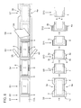
Fig. 6] Fig. 6 is a process drawing showing a production method for the disposable diaper inFig. 1 . - [
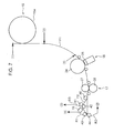
Fig. 7] Fig. 7 is a schematic view showing the configuration of a production device used in the production method shown inFig. 6 . - [
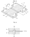
Fig. 8] Fig. 8 is a perspective view showing the schematic configuration of a folding unit shown inFig. 7 in its enlarged state. - [
Fig. 9] Fig. 9 is a cross-sectional view showing a part of the folding unit shown inFig. 8 . - [
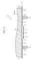
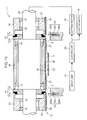
Fig. 10] Fig. 10 is a cross-sectional view showing the schematic configuration of a welding unit shown inFig. 7 . - [
Fig. 11] Fig. 11 is a cross-sectional view showing the schematic configuration of a cutting unit shown inFig. 7 and also shows the electrical configuration relating to the cutting unit. - Hereinafter, a description will be given of an embodiment of the present invention with reference to the accompanying drawings. Note that the following embodiment is a materialized example of the present invention but does not limit the technical scope of the present invention.
- With reference to
Figs. 1 and2 , adisposable diaper 1 as an example of disposable wearing articles is a so-called underpants-shaped diaper. Specifically, adisposable diaper 1 has a diaper main body (main body portion) 2 that extends from the front belly part to the back part via the crotch part of a wearer and four side panel pieces (side pieces) 3 and 4 each of which protrudes from both ends in the longitudinal direction (vertical direction inFig. 2 ) of the diapermain body 2 in the width direction (horizontal direction inFig. 2 ) of the diapermain body 2 when thedisposable diaper 1 is worn. Thedisposable diaper 1 is formed in an underpants shape when the respectiveside panel pieces 3 are bonded to each other through theirside seal portions 5 and the respectiveside panel pieces 4 are bonded to each other through theirside seal portions 6 in a state in which the diapermain body 2 is folded in two. As a result, the respectiveside panel pieces 3 bonded to each other through theside seal portions 5 and the respectiveside panel pieces 4 bonded to each other through theside seal portions 6 constitute a pair of side portions that covers the side surfaces of the lumbar part of a wearer. - Hereinafter, a description will be given of the specific configuration of the
disposable diaper 1 with reference toFigs. 1 to 5 . - The diaper
main body 2 is capable of absorbing body wastes (for example, urine) of a wearer and has elasticity at its appropriate portions. Specifically, the diapermain body 2 has anabsorber 7 capable of absorbing body wastes of a wearer,elastic members 8 for legs provided at positions corresponding to the crotch part of the wearer, a pair ofelastic members 9 for waist provided at positions corresponding to the front belly part and the back part of the wearer, and inner andouter sheets elastic members 8 for legs, and theelastic members 9 for waist between them. - The
inner sheet 10 is a substantially rectangular sheet that is directed to the body surface side of a wearer when thedisposable diaper 1 is worn and has liquid permeability. Theinner sheet 10 can be constituted by, for example, a nonwoven sheet and/or a mesh sheet having liquid permeability. - The
outer sheet 11 is a sheet that is directed to the outer side of a wearer when thedisposable diaper 1 is worn and has liquid impermeability. Theouter sheet 11 can be constituted by a polyethylene film or a nonwoven fabric having water repellency and air permeability. In addition, theouter sheet 11 is a substantially rectangular sheet having a size equivalent to that of theinner sheet 10. - The absorber 7 absorbs liquid that passes through the
inner sheet 10. Specifically, theabsorber 7 is molded in such a way as to stack crashed pulps or materials in which crashed pulps and highly water-absorptive polymers are mixed together. In addition, theabsorber 7 has a substantially rectangular shape or a hourglass shape having a longitudinal size smaller than those of therespective sheets respective sheets absorber 7 is arranged between thesheets respective sheets respective sheets Fig. 3 , theabsorber 7 is bonded to thesheets inner sheet 10 and theouter sheet 11. - The respective
elastic members 8 for legs are such that the diapermain body 2 is raised and brought into intimate contact with the crotch part of a wearer when thedisposable diaper 1 is worn to prevent body wastes from leaking from the gap between the diapermain body 2 and the body surface of the wearer. At least parts of the respectiveelastic members 8 for legs are provided at positions on both outer sides in the width direction of theabsorber 7 and at positions between the respectiveside panel pieces 3 and between the respectiveside panel pieces 4. In addition, the respectiveelastic members 8 for legs are attached on the diapermain body 2 in their expanding state in the longitudinal direction of the diapermain body 2. As shown inFig. 4 , the respectiveelastic members 8 for legs are bonded to thesheets inner sheet 10 and theouter sheet 11. The respectiveelastic members 8 for legs can be constituted by polyurethane, natural rubber, or sheets or threads made of a thermoplastic resin. - The respective
elastic members 9 for waist are such that the diapermain body 2 is fastened to the front belly part or the back part of a wearer when thedisposable diaper 1 is worn to prevent thedisposable diaper 1 from being pulled down. The respectiveelastic members 9 for waist are attached on the diapermain body 2 under a stretched state in the width direction of theabsorber 7. As shown inFig. 5 , the respectiveelastic members 9 for waist are bonded to thesheets inner sheet 10 and theouter sheet 11. The respectiveelastic members 9 for waist can be constituted by polyurethane, natural rubber, or sheets or threads made of a thermoplastic resin. - The respective
side panel pieces 3 extend from both end portions in the longitudinal direction (front and rear direction) of the diapermain body 2 to one side in the horizontal direction (right side inFigs. 1 and2 ) and has elasticity in the horizontal direction. Agap portion 3a is formed between the respectiveside panel pieces 3 and used as a leg hole when the right edge portions of the respectiveside panel pieces 3 are bonded to each other through theside seal portions 5. As shown inFig. 3 , the respectiveside panel pieces 3 are bonded to thesheets inner sheet 10 and theouter sheet 11 on the right side of theabsorber 7. - In addition, the respective
side panel pieces 3 are sheets made of a thermoplastic material. Specifically, the respectiveside panel pieces 3 can be constituted by an elastic film, an elastic nonwoven fabric, a laminated body of an elastic film and a nonwoven fabric, or a laminated body of thread rubber and a nonwoven fabric each of which is made of one or at least two of the materials of a block copolymer of polystyrene, a block copolymer of polyisoprene, a block copolymer of polybutadiene, a copolymer of ethylene, natural rubber, and urethane. - The respective
side panel pieces 4 extend from both end portions in the longitudinal direction of the diapermain body 2 to one side in the horizontal direction (left side inFigs. 1 and2 ) and has elasticity in the horizontal direction. Agap portion 4a is formed between the respectiveside panel pieces 4 and used as a leg hole when the left edge portions of the respectiveside panel pieces 4 are bonded to each other through theside seal portions 6. As shown inFig. 3 , the respectiveside panel pieces 4 are bonded to thesheets inner sheet 10 and theouter sheet 11 on the left side of theabsorber 7. - In addition, the respective
side panel pieces 4 are sheets made of a thermoplastic material. Specifically, the respectiveside panel pieces 4 can be constituted by an elastic film, an elastic nonwoven fabric, a laminated body of an elastic film and a nonwoven fabric, or a laminated body of thread rubber and a nonwoven fabric each of which is made of one or at least two of the materials of a block copolymer of polystyrene, a block copolymer of polyisoprene, a block copolymer of polybutadiene, a copolymer of ethylene, natural rubber, and urethane. - Hereinafter, a description will be given of a method of producing the
disposable diaper 1 with reference toFig. 6 . The method of producing thedisposable diaper 1 mainly includes the following steps S1 to S 13. - In step S1, an
outer sheet band 11 A for constituting theouter sheet 11 is continuously conveyed in its longitudinal direction. - In step S2, the
elastic members 9 for waist are bonded to the continuously-conveyedouter sheet band 11A. Specifically, theelastic members 9 for waist are arranged at two parts on theouter sheet band 11 A with an interval corresponding to the longitudinal size of theabsorber 7. In addition, theelastic members 9 for waist at the two parts attached in step S2 are separated from each other in the longitudinal direction (flow direction) of theouter sheet band 11A. Moreover, the respectiveelastic members 9 for waist are attached on theouter sheet band 11A under a stretched state in the width direction of theouter sheet band 11 A. - In step S3, the
absorber 7 is bonded to the continuously-conveyedouter sheet band 11A. Specifically, theabsorber 7 is arranged between the respectiveelastic members 9 for waist in a state that a longitudinal direction of theabsorber 7 is disposed along the longitudinal direction of theouter sheet band 11 A. - In step S4, the pair of
elastic members 8 for legs is bonded to the continuously-conveyedouter sheet band 11A. Theelastic members 8 for legs are arranged at a central position in the longitudinal direction of theabsorber 7 on theouter sheet band 11A and at positions on both outer sides in the width direction of theabsorber 7. In addition, the respectiveelastic members 8 for legs are attached on theouter sheet band 11 A under a stretched state in the longitudinal direction of theouter sheet band 11 A. - In step S5, a
side panel band 3A for constituting theside panel pieces 3 and aside panel band 4A for constituting theside panel pieces 4 are bonded to the continuously-conveyedouter sheet band 11A. Theside panel bands side panel bands outer sheet band 11 A and bonded to the edge portions of theouter sheet band 11 A on the outer side of theelastic members 8 for legs. At this time, theside panel bands outer sheet band 11 A in a state of protruding from theouter sheet band 11 A. - In step S6, an
inner sheet band 10A for constituting theinner sheet 10 is bonded to the continuously-conveyedouter sheet band 11A. Specifically, theinner sheet band 10A is continuously supplied in a state that a longitudinal direction of theinner sheet band 10A is disposed along the longitudinal direction of theouter sheet band 11A and bonded to theouter sheet band 11 A in a state of being aligned with theouter sheet band 11 A in the width direction. In step S6, the respectiveelastic members absorber 7 are entirely sandwiched between thesheet bands side panel bands sheet bands - In step S7, the
side panel bands gap portions side panel bands side panel bands absorber 7. - In step S8, the
sheet bands side panel bands sheet bands side panel bands elastic members 9 for waist. In step S8, the partly-finished product 1Z is formed in which theside panel bands side panel pieces - In step S9, the diaper
main body 2 of the partly-finished product 1Z is folded in two at the central position in the longitudinal direction (folding step). Thus, theside panel pieces 3 face each other, and theside panel pieces 4 face each other. - In step S10, the respective mutually-overlapping
side panel pieces 3 and the respective mutually-overlappingside panel pieces 4 are tentatively fastened to each other (tentative fastening step). Specifically, in step S10,tentative fastening portions portions tentative fastening portions side panel pieces 3 and the respectiveside panel pieces 4 to each other to prevent the diapermain body 2 from being unfolded. - In step S11, the
side seal portions 5 are formed on the respectiveside panel pieces 3, and theside seal portions 6 are formed on the respective side panel pieces 4 (welding step). That is, the respectiveside panel pieces 3 and the respectiveside panel pieces 4 are welded to each other by ultrasonic welding. - In step S12, the separated
portion 3b on the outer side of the respectiveside seal portions 5 of the respectiveside panel pieces 3 is cut off, and the separatedportion 4b on the outer side of the respectiveside seal portions 6 of the respectiveside panel pieces 4 is cut off (cutting step). Thus, the edge portions of the respectiveside panel pieces 3 and the edge portions of the respectiveside panel pieces 4 are lined up to enhance the appearance. Further, the separatedportions unit 18 that will be described later (discarding step). - In step S 13, the respective
side panel pieces 3 and the respectiveside panel pieces 4 are folded toward the inner side of the diapermain body 2. Thus, thedisposable diaper 1 in a form suitable to be packaged is completed. - Hereinafter, a description will be given, with reference to
Figs. 6 and7 , of a disposable diaper production device 14 used in steps S9 to S12 described above. - The production device 14 has a
folding unit 15 that executes steps S9 and S10, awelding unit 16 that executes step S11, a cuttingunit 17 that executes step S12, the discardingunit 18 that discards the separatedportion 4b formed by the cuttingunit 17, a conveying unit 19 (seeFig. 11 ) that conveys the partly-finished product 1Z torespective units 15 to 18 described above, a controller 20 (seeFig. 11 ) that controls the driving of therespective units 15 to 19, and an input unit 21 (seeFig. 11 ) used to input a setting value or the like to thecontroller 20. - With reference to
Figs. 7 and8 , thefolding unit 15 has a plurality of sets of first andsecond holding plates drum 15a that is rotatable about a predetermined axis and has an opening/closing mechanism (not shown) that opens/closes therespective holding plates drum 15a. Note thatFig. 8 shows only one set of the holdingplates - The
respective holding plates finished product 1Z by adsorption. Specifically, therespective holding plates suction holes respective holding plates finished product 1Z held by therespective holding plates - Moreover, the first holding
plate 22 has tentativefastening protruding portions 22b that protrude from its front surface. While, thesecond holding plate 23 has tentative fastening recessedportions 23b that are capable of receiving the tentativefastening protruding portions 22b at the rotation described above. The tentativefastening protruding portions 22b and the tentative fastening recessedportions 23b are arranged at parts corresponding to theside panel pieces 3 and 4 (the separatedportions finished product 1Z held by adsorption. Therefore, when therespective holding plates side panel pieces fastening protruding portions 22b and the tentative fastening recessedportions 23b as shown inFig. 9 to form thetentative fastening portions Fig. 9 , the tentativefastening protruding portions 22b are constituted by screw portions. Therefore, the protruding amount of the tentativefastening protruding portions 22b can be adjusted in such a way as to adjust the fastening degree of the tentativefastening protruding portions 22b with respect to thefist holding plate 22. Note that although theside panel pieces tentative fastening portions side panel pieces tentative fastening portions - Next, a description will be given of the operation of the
folding unit 15. - When the
drum 15a rotates to a predetermined receiving position, therespective holding plates Fig. 8 to receive the unfolded partly-finished product 1Z from an upstream-side line (line in which step S8 is executed). When thedrum 15a rotates to the predetermined folding position, therespective holding plates finished product 1Z and form thetentative fastening portions drum 15a rotates to a predetermined transferring position, therespective holding plates Fig. 8 to transfer the folded partly-finished product 1Z to the conveyingunit 19. - The
welding unit 16 forms theside seal portions finished product 1Z being conveyed by the conveyingunit 19 that will be described later. Specifically, as shown inFigs. 7 and10 , thewelding unit 16 has ananvil 24 that is rotatable about a predetermined rotating axis and a pair ofhorns 25 that welds the respectiveside panel pieces 3 to each other and the respectiveside panel pieces 4 to each other by ultrasonic welding between the pair ofhorns 25 and theanvil 24. - The
anvil 24 has an anvilmain body 24a and a pair of protrudingportions 24b that protrudes from the anvilmain body 24a to an outside. The respective protrudingportions 24b are arranged at an interval corresponding to the pitch between theside seal portions - Then, the
welding unit 16 applies mechanical vibrations from thehorns 25 to the respectiveside panel pieces side panel pieces portions 24b and the pair ofhorns 25 to form theside seal portions - The cutting
unit 17 cuts off theside panel pieces finished product 1Z being conveyed by the conveyingunit 19 that will be described later. Specifically, as shown inFigs. 7 and11 , the cuttingunit 17 has a drivingshaft 26, a pair of drivingblades 27 that rotates and drives in response to the rotation of the drivingshaft 26, a pair of drivenblades 28 that cuts off the respectiveside panel pieces driving blades 27, aninner support roller 29 provided at the periphery of the drivingshaft 26 between therespective driving blades 27, a pair ofouter support rollers 30 provided at the periphery of the drivingshaft 26 on the outer sides of therespective driving blades 27, and a cuttingmotor 33 that drives the drivingshaft 26. - The
respective driving blades 27 have anattachment portion 27b fixed to the drivingshaft 26 and a driving blademain body 27a detachably attached to theattachment portion 27b. - The respective driven
blades 28 have a driven blademain body 28a and asupport portion 28b that rotatably supports the driven blademain body 28a about rotatingshaft 28c. Note that althoughFig. 11 shows a state in which the driven blademain bodies 28a separate from the driving blademain bodies 27a downward, the driven blademain bodies 28a and the driving blademain bodies 27a are actually arranged such that the upper potions of the driven blademain bodies 28a and the lower portions of the driving blademain bodies 27a overlap each other when viewed along the axial line of the drivingshaft 26. In addition, the driven blademain bodies 28a rotate in response to the movement of the partly-finished product 1Z to be conveyed by the conveyingunit 19. - The
inner support roller 29 and the respectiveouter support rollers 30 are used to cause a difference in the rate between a conveying rate for conveying the partly-finished product 1Z by the conveyingunit 19 that will be described later and the rotating rate of therespective driving blades 27. Specifically, theinner support roller 29 is attached to the periphery of the drivingshaft 26 viabearings 31 on the inner sides of therespective driving blades 27. Similarly, the respectiveouter support rollers 30 are attached to the periphery of the drivingshaft 26 viabearings 32 on the outer sides of therespective driving blades 27. - As shown in
Fig. 7 , the conveyingunit 19 conveys the partly-finished product 1Z along a main path F1 that extends from thefolding unit 15 to the next step (rollers Fig. 7 ) via thewelding unit 16 and the cuttingunit 17. In addition, the conveyingunit 19 conveys the separatedportions Fig. 6 ) formed by the cuttingunit 17 to the discardingunit 18 along a discarding path F2 that branches off from the main path F1 on the downstream side of the cuttingunit 17. The discardingunit 18 is used to attract the separatedportions unit 19 and guide the separatedportion - Hereinafter, a description will be given of the specific configuration of the conveying
unit 19 with reference toFig. 10 . - The conveying
unit 19 has aninner support belt 34 that supports the partly-finished product 1Z between the respective protrudingportions 24b of theanvil 24, a pair of outer support belts (sandwiching member) 35 that supports the partly-finished product 1Z (theside panel pieces 3 and 4) on the outer sides of the respective protrudingportions 24b, a mainbody sandwiching belt 36 that sandwiches the diapermain body 2 between the mainbody sandwiching belt 36 and theinner support belt 34, a pair ofpanel sandwiching belts 37 that sandwiches theside panel pieces panel sandwiching belts 37 and theinner support belt 34, a pair of separated portion sandwiching belts (sandwiching members) 38 that sandwiches parts corresponding to the separated portions of theside panel pieces portion sandwiching belt 38 and the respectiveouter support belts 35, a conveying motor 39 (seeFig. 11 ) that rotates a driving roller (not shown) that drives therespective support belts rollers 40 to 44 (seeFig. 7 ) that holds therespective belts 34 to 38. - As shown in
Figs. 10 and11 , therespective support belts welding unit 16 and the cuttingunit 17 in a state of being pressed to the peripheral surface of the anvilmain body 24a of thewelding unit 16 and the peripheral surfaces of thesupport rollers unit 17. - Here, the
respective belts 34 to 38 sandwich the partly-finished product 1Z from its front and rear sides on both sides in the width direction of a region of the partly-finished product 1Z, the region including welding positions by thewelding unit 16 and cutting positions by the cuttingunit 17. Specifically, theinner support belt 34, the mainbody sandwiching belt 36, and the respectivepanel sandwiching belts 37 are arranged between the respective protrudingportions 24b of theanvil 24 and between the respective cutting blademain bodies 27a. While, the respectiveouter support belts 35 and the respective separatedportion sandwiching belts 38 are arranged on the outer sides of the respective protrudingportions 24b and on the outer sides of the respective cutting blademain bodies 27a. Thus, the partly-finished product 1Z can be welded and cut off with its both sides in the width direction of the welding positions and the cutting positions held. - Hereinafter, a description will be given in more detail of the circulating operations of the
respective belts 34 to 38 with reference toFigs. 7 ,10 , and11 . - The
inner support belt 34 moves from a point (1) in the main path F1 shown inFig. 7 to the transferring position of thefolding unit 15 to receive the partly-finished product 1Z. Here, theinner support belt 34 is provided with an adsorption mechanism (not shown), and the partly-finished product 1Z is adsorbed onto theinner support belt 34 by the adsorption force of the adsorption mechanism. - When the
respective sandwiching belts 36 to 38 join so as to face theinner support belt 34 at a point (2) in the main path F1, the partly-finished product 1Z is sandwiched between theinner support belt 34 and therespective sandwiching belts - When the respective
outer support belts 35 join so as to face the separatedportion sandwiching belts 38 at a point (3) on the upstream side of thewelding unit 16 in the main path F1, parts of the partly-finished product 1Z corresponding to the separatedportions respective belts - Then, the
respective belts 34 to 38 pass through thewelding unit 16 and the cuttingunit 17 in this state. - Beginning at the
roller 40 on the downstream side of the cuttingunit 17, the respectiveouter support belts 35 and the respective separatedportion sandwiching belts 38 move along the discarding path F2 that branches off from the main path F1 along which theother belts portions finished product 1Z or torn off in a case in which the partly-finished product 1Z is imperfectly cut off. - Among the
respective belts inner support belt 34 returns to the point (1) along a first return path R1 beginning at theroller 43. While, therespective sandwiching belts roller 44. Thus, the partly-finished product 1Z sandwiched by therespective belts - The
respective belts rollers outer support belts 35 return to the point (3) along a third return path R3 beginning at theroller 41. While, the respective separatedportion sandwiching belts 38 return to the point (2) along the second return path R2 beginning at theroller 42. Thus, the separatedportions respective belts portions unit 18 that is provided in the vicinity of therespective rollers - Meanwhile, as shown in
Fig. 11 , therespective support belts support rollers shaft 26. Therefore, a conveying rate for conveying the partly-finished product 1Z with therespective support belts controller 20 that controls the conveying rate and the rotating rate. - The
controller 20 sets the conveying rate for conveying the partly-finished product 1Z with the conveyingunit 19 and the rotating rate (angular rate) of thedriving blades 27 based on a commanded value of the conveying rate input by theinput unit 21 and outputs the conveying rate and the rotating rate to the cuttingmotor 33 and the conveyingmotor 39. - Here, the
controller 20 sets the rotating rate of the driving blades at a rate faster than a target conveying rate based on the input from theinput unit 21. Thus, thedriving blades 27 move faster than the respectiveside panel pieces side panel pieces controller 20 according to the embodiment sets the rotating rate at an angular rate 1.5 to 2.0 times with respect to the target conveying rate. - As described above, both side portions in the width direction of the welded portions of the respective
side panel pieces side panel pieces 3 are welded to each other and the respectiveside panel pieces 4 are welded to each other. Therefore, the respectiveside panel pieces - Accordingly, the welding positions of the respective
side panel pieces - Further, the embodiment produces the following effects.
- In step S12, the end portions of the
side panel pieces disposable diaper 1 can be enhanced. - Here, in the embodiment, in a state in which both side positions in the width direction of the region of the
side panel pieces side panel pieces 3 can be welded to each other while theside panel pieces 4 can be welded to each other and the respectiveside panel pieces side panel pieces - In addition, the separated
portions portions portions portions side panel pieces side panel pieces - Further, the separated
portions unit 18 while being constrained between the respectiveouter support belts 35 and the respective separatedportion sandwiching belts 38. In this way, it becomes possible to tear off the imperfectly cut-offseparated portions portions unit 18 as described above. - In addition, in the embodiment, the
tentative fastening portions side panel pieces 3 are welded to each other and the respectiveside panel pieces 4 are welded to each other after the diapermain body 2 of the partly-finished product 1Z is folded, the diapermain body 2 can be prevented from being unfolded by thetentative fastening portions finished product 1Z is held with respect to theinner support belt 34 by adsorption in the range between the point (1) and the point (2) inFig. 7 . Therefore, the diapermain body 2 can be effectively prevented from being unfolded in this range. - Note that although the embodiment describes the
disposable diaper 1 in which theside panel pieces inner sheet 10 and theouter sheet 11 as shown inFig. 3 , thedisposable diaper 1 can also have a configuration in which the respectiveside panel pieces inner sheet 10. In this case, it is necessary to reverse the order of steps S5 and S6 shown inFig. 6 . - In addition, although the embodiment exemplifies the method in which the
side panel bands outer sheet band 11A in step S5 and cut off in step S7 as shown inFig. 6 , the method of forming theside panel pieces side panel pieces outer sheet band 11A at a pitch corresponding to thegap portions - Moreover, the respective
elastic members 8 for legs and the respectiveelastic members 9 for waist may be bonded to the inner side of theinner sheet 10 and/or the outer side of the outer sheet. - Note that the specific embodiment described above mainly includes the inventions having the following configurations.
- In order to solve the problem, the present invention provides a disposable diaper production method for producing a disposable diaper having a main body portion that extends from a front belly part to a back part via a crotch part and a pair of side portions that covers side surfaces of a lumbar part of a wearer when the disposable diaper is worn, the method comprising: a constituents producing step of producing constituents including the main body portion and four side pieces each of which protrudes from both ends of the main body portion in a longitudinal direction to both outer sides in a width direction of the main body portion; a folding step of folding the main body portion in the longitudinal direction to form two sets of two mutually-overlapping side pieces; a conveying step of conveying the folded constituents along the longitudinal direction; and a welding step of welding the mutually-overlapping side pieces to each other along a conveying direction for each set of the two side pieces of the constituents being conveyed to form the pair of side portions, wherein the conveying step conveys the constituents in a state in which both side portions in the width direction of a portion of the respective side pieces to be welded are held for each set of the two side pieces when the respective side pieces are welded to each other in the welding step.
- In addition, the present invention provides a disposable diaper production device for producing a disposable diaper having a main body portion that extends from a front belly part to a back part via a crotch part and a pair of side portions that covers side surfaces of a lumbar part of a wearer when the disposable diaper is worn, the device comprising: a folding unit that folds the main body portion in a longitudinal direction to form two sets of two mutually-overlapping side pieces for constituents including the main body portion and four side pieces each of which protrudes from both ends of the main body portion in the longitudinal direction to both outer sides in a width direction of the main body portion; a conveying unit that conveys the folded constituents along the longitudinal direction; and a welding unit that welds the mutually-overlapping side pieces to each other along a conveying direction for each set of the two side pieces of the constituents being conveyed to form the pair of side portions, wherein the conveying unit conveys the constituents in a state in which both side portions in the width direction of a portion of the respective side pieces to be welded are held for each set of the two side pieces when the respective side pieces are welded to each other by the welding unit.
- According to these inventions, both the side portions in the width direction of the portion of the respective side pieces to be welded are held when the respective side pieces are welded to each other. Therefore, the respective side pieces can be prevented from moving when the respective side pieces are welded to each other.
- Thus, according to the respective inventions, the welding position of the respective side pieces can be accurately managed.
- The production method preferably further comprises a cutting step of cutting off end portions of the two side pieces uniformly for each set of the two side pieces after the welding step, wherein the conveying step preferably conveys the constituents in a state in which both side portions in the width direction of a region of the constituent, the region including the portion to be welded in the welding step and a portion to be cut off in the cutting step, are held over a period between the welding step and the cutting step.
- In addition, the production device preferably further comprises a cutting unit that cuts off end portions of the two side pieces uniformly for each set of the two side pieces welded by the welding unit, wherein the conveying unit preferably conveys the constituents in a state in which both side portions in the width direction of a region of the constituent, the region including the portion to be welded by the welding unit and a portion to be cut off by the cutting unit, are held over a range between the welding unit and the cutting unit.
- According to these aspects, the end portions of the two side pieces are cut off uniformly. Therefore, the appearance of the disposable diaper can be enhanced.
- Here, in the respective aspects, in a state in which both the side portions in the width direction of the region of the constituent, the region including the welding target portion and the cutting target portions, are held, the side pieces can be welded to each other and cut off. Thus, the respective side pieces can also be prevented from moving when they are cut off. Therefore, the cutting positions as well as the welding positions can also be reliably managed as described above.
- The production method preferably further comprises a discarding step of discarding separated portions of the respective side pieces, separated in the cutting step, to a discarding unit, wherein the conveying step preferably conveys, after the cutting step, portions other than the separated portions of the constituents along a main path while conveying the separated portions to the discarding unit along a discarding path that branches off from the main path.
- In addition, the disposable diaper production device preferably further comprises a discarding unit that discards separated portions of the respective side pieces separated by the cutting unit, wherein the conveying unit preferably conveys, on a downstream side of the cutting unit, portions other than the separated portions of the constituents along a main path while conveying the separated portions to the discarding unit along a discarding path that branches off from the main path.
- According to these aspects, the separated portions are conveyed along the path (discharge path), which is not used for the portions other than the separated portions. Therefore, the separated portions can be torn off from the other portions even in a state in which the separated portions are imperfectly cut off from the other portions (for example, a state in which the portions of the side pieces across their cutting-plane line are joined to each other due to the tangling of fibers when the side pieces are made of, for example, a nonwoven fabric).
- In the production method, the conveying step preferably conveys portions corresponding to the separated portions while sandwiching the portions corresponding to the separated portions with a pair of sandwiching members from both front and rear sides thereof over a period between the welding step and the discarding step and separates the pair of sandwiching members from each other at the discarding unit.
- In addition, in the production device, the conveying unit preferably has a pair of sandwiching members, conveys portions corresponding to the separated portions while sandwiching the portions corresponding to the separated portions with the pair of sandwiching members from both front and rear sides thereof over a range between the welding unit and the discarding unit, and separates the pair of sandwiching members from each other at the discarding unit.
- According to these aspects, the separated portions are released at the discarding unit while being constrained between the pair of sandwiching members. In this way, it becomes possible to tear off the imperfectly cut-off separated portions from the other portions and reliably discard the separated portions at the discarding unit as described above.
- The production method preferably further comprises a tentative fastening step of tentatively fastening, before the welding step, the respective mutually-overlapping side pieces to each other at positions corresponding to the separated portions of the respective side pieces to be separated in the cutting step.
- In addition, the production device preferably further comprises a tentative fastening unit that tentatively fastens, for the constituents before the respective side pieces are welded by the welding unit, the respective mutually-overlapping side pieces to each other at positions corresponding to the separated portions of the respective side pieces to be separated by the cutting unit.
- According to these aspects, at a stage before the respective side pieces are welded to each other after the main body portion is folded, the main body portion can be prevented from being unfolded by the tentative fastening unit.
Claims (10)
- A disposable diaper production method for producing a disposable diaper having a main body portion that extends from a front belly part to a back part via a crotch part and a pair of side portions that covers side surfaces of a lumbar part of a wearer when the disposable diaper is worn, the method comprising:a constituents producing step of producing constituents including the main body portion and four side pieces each of which protrudes from both ends of the main body portion in a longitudinal direction to both outer sides in a width direction of the main body portion;a folding step of folding the main body portion in the longitudinal direction to form two sets of two mutually-overlapping side pieces;a conveying step of conveying the folded constituents along the longitudinal direction; anda welding step of welding the mutually-overlapping side pieces to each other along a conveying direction for each set of the two side pieces of the constituents being conveyed to form the pair of side portions, whereinthe conveying step conveys the constituents in a state in which both side portions in the width direction of a portion of the respective side pieces to be welded are held for each set of the two side pieces when the respective side pieces are welded to each other in the welding step.
- The disposable diaper production method according to claim 1, further comprising:a cutting step of cutting off end portions of the two side pieces uniformly for each set of the two side pieces after the welding step, whereinthe conveying step conveys the constituents in a state in which both side portions in the width direction of a region of the constituent, the region including the portion to be welded in the welding step and a portion to be cut off in the cutting step, are held over a period between the welding step and the cutting step.
- The disposable diaper production method according to claim 2, further comprising:a discarding step of discarding separated portions of the respective side pieces, separated in the cutting step, to a discarding unit, whereinthe conveying step conveys, after the cutting step, portions other than the separated portions of the constituents along a main path while conveying the separated portions to the discarding unit along a discarding path that branches off from the main path.
- The disposable diaper production method according to claim 3, wherein the conveying step conveys portions corresponding to the separated portions while sandwiching the portions corresponding to the separated portions with a pair of sandwiching members from both front and rear sides thereof over a period between the welding step and the discarding step and separates the pair of sandwiching members from each other at the discarding unit.
- The disposable diaper production method according to any one of claims 2 to 4, further comprising:a tentative fastening step of tentatively fastening, before the welding step, the respective mutually-overlapping side pieces to each other at positions corresponding to the separated portions of the respective side pieces to be separated in the cutting step.
- A disposable diaper production device for producing a disposable diaper having a main body portion that extends from a front belly part to a back part via a crotch part and a pair of side portions that covers side surfaces of a lumbar part of a wearer when the disposable diaper is worn, the device comprising:a folding unit that folds the main body portion in a longitudinal direction to form two sets of two mutually-overlapping side pieces for constituents including the main body portion and four side pieces each of which protrudes from both ends of the main body portion in the longitudinal direction to both outer sides in a width direction of the main body portion;a conveying unit that conveys the folded constituents along the longitudinal direction; anda welding unit that welds the mutually-overlapping side pieces to each other along a conveying direction for each set of the two side pieces of the constituents being conveyed to form the pair of side portions, whereinthe conveying unit conveys the constituents in a state in which both side portions in the width direction of a portion of the respective side pieces to be welded are held for each set of the two side pieces when the respective side pieces are welded to each other by the welding unit.
- The disposable diaper production device according to claim 6, further comprising:a cutting unit that cuts off end portions of the two side pieces uniformly for each set of the two side pieces welded by the welding unit, whereinthe conveying unit conveys the constituents in a state in which both side portions in the width direction of a region of the constituent, the region including the portion to be welded by the welding unit and a portion to be cut off by the cutting unit are held over a range between the welding unit and the cutting unit.
- The disposable diaper production device according to claim 7, further comprising:a discarding unit that discards separated portions of the respective side pieces separated by the cutting unit, whereinthe conveying unit conveys, on a downstream side of the cutting unit, portions other than the separated portions of the constituents along a main path while conveying the separated portions to the discarding unit along a discarding path that branches off from the main path.
- The disposable diaper production device according to claim 8, wherein the conveying unit has a pair of sandwiching members, conveys portions corresponding to the separated portions while sandwiching the portions corresponding to the separated portions with the pair of sandwiching members from both front and rear sides thereof over a range between the welding unit and the discarding unit, and separates the pair of sandwiching members from each other at the discarding unit.
- The disposable diaper production device according to any one of claims 7 to 9, further comprising:a tentative fastening unit that tentatively fastens, for the constituents before the respective side pieces are welded by the welding unit, the respective mutually-overlapping side pieces to each other at positions corresponding to the separated portions of the respective side pieces to be separated by the cutting unit.
Applications Claiming Priority (2)
| Application Number | Priority Date | Filing Date | Title |
|---|---|---|---|
| JP2012280109 | 2012-12-21 | ||
| PCT/JP2013/007470 WO2014097635A1 (en) | 2012-12-21 | 2013-12-19 | Disposable diaper production method and production device |
Publications (4)
| Publication Number | Publication Date |
|---|---|
| EP2915512A1 true EP2915512A1 (en) | 2015-09-09 |
| EP2915512A4 EP2915512A4 (en) | 2016-06-22 |
| EP2915512B1 EP2915512B1 (en) | 2018-06-27 |
| EP2915512B8 EP2915512B8 (en) | 2018-08-29 |
Family
ID=50977994
Family Applications (1)
| Application Number | Title | Priority Date | Filing Date |
|---|---|---|---|
| EP13863778.0A Not-in-force EP2915512B8 (en) | 2012-12-21 | 2013-12-19 | Disposable diaper production method and production device |
Country Status (5)
| Country | Link |
|---|---|
| US (1) | US10709614B2 (en) |
| EP (1) | EP2915512B8 (en) |
| JP (1) | JP6298412B2 (en) |
| CN (1) | CN104822350B (en) |
| WO (1) | WO2014097635A1 (en) |
Families Citing this family (1)
| Publication number | Priority date | Publication date | Assignee | Title |
|---|---|---|---|---|
| CN115137561B (en) * | 2022-09-02 | 2023-11-17 | 浙江德恒机械有限公司 | Panty-shape diapers production facility |
Family Cites Families (36)
| Publication number | Priority date | Publication date | Assignee | Title |
|---|---|---|---|---|
| CA1298818C (en) * | 1987-12-16 | 1992-04-14 | Paul Theodore Van Gompel | Method and apparatus for making a disposable incontinence garment or training pant |
| JPH03126529A (en) | 1989-10-11 | 1991-05-29 | Mitsuo Fujisawa | Ultrasonic working machine |
| US5246433A (en) | 1991-11-21 | 1993-09-21 | The Procter & Gamble Company | Elasticized disposable training pant and method of making the same |
| GB2283532B (en) * | 1993-10-22 | 1996-07-31 | Ykk Europ Ltd | Method of manufacturing a tape having a succession of surface-type fastener pieces |
| US5626711A (en) * | 1994-05-27 | 1997-05-06 | Paragon Trade Brands, Inc. | Apparatus for producing elasticized undergarment products |
| US5649336A (en) * | 1994-11-23 | 1997-07-22 | Kimberly-Clark Worldwide, Inc. | Child's mitt wipe |
| US5772825A (en) * | 1994-12-22 | 1998-06-30 | The Procter & Gamble Company | Method for making an undergarment having side seams |
| US5743994A (en) * | 1995-11-06 | 1998-04-28 | Kimberly-Clark Worldwide, Inc. | Apparatus for making an absorbent article with asymmetric leg elastics |
| US5735991A (en) * | 1995-10-20 | 1998-04-07 | Olympus Optical Co., Ltd. | Method for sealing and cutting pads and moving the sealed and cut pads to a take off position by a moving support |
| AU3763399A (en) * | 1998-04-28 | 1999-11-16 | Denovus L.L.C. | Method and apparatus for die cutting and making laminate articles |
| ES2270973T3 (en) * | 2001-07-20 | 2007-04-16 | Fameccanica.Data S.P.A. | PROCEDURE AND DEVICE FOR COLLECTION OF MATERIALS. |
| US7056313B2 (en) * | 2001-12-20 | 2006-06-06 | Kimberly-Clark Worldwide, Inc. | Aesthetically improved side panels for disposable garment and methods of making the same |
| SE0200988D0 (en) * | 2002-04-02 | 2002-04-02 | Sca Hygiene Prod Ab | Procedure for manufacturing a pant diaper |
| JP4318452B2 (en) * | 2002-12-13 | 2009-08-26 | ユニ・チャーム株式会社 | Method for producing disposable wearing article |
| JP4297715B2 (en) * | 2003-03-31 | 2009-07-15 | ユニ・チャーム株式会社 | SEALING DEVICE AND SEALING METHOD USING THE SEALING DEVICE |
| US20050092146A1 (en) * | 2003-10-29 | 2005-05-05 | Kimberly-Clark Worldwide, Inc. | Method and apparatus for removing material from a moving substrate |
| JP4437060B2 (en) | 2004-06-28 | 2010-03-24 | 株式会社瑞光 | Seal system |
| US20070095463A1 (en) * | 2004-08-27 | 2007-05-03 | Denovus Llc | Method and apparatus for die cutting and making laminate articles |
| US7285178B2 (en) * | 2004-09-30 | 2007-10-23 | Kimberly-Clark Worldwide, Inc. | Method and apparatus for making a wrapped absorbent core |
| DE102006013397A1 (en) * | 2006-03-23 | 2007-10-04 | WINKLER + DüNNEBIER AG | Apparatus and method for cutting flat material blanks from flat material sheet |
| US7753099B2 (en) * | 2006-10-05 | 2010-07-13 | The Procter & Gamble Company | Method and apparatus for making article having side seams |
| ITTO20080325A1 (en) * | 2008-04-30 | 2008-07-30 | Fameccanica Data Spa | "EXTENSIBLE LAMINAR MATERIAL, IN PARTICULAR FOR HYGIENE-SANITARY ARTICLES, AND RELATIVE PROCESS OF PROCESSING" |
| JP5318490B2 (en) * | 2008-08-07 | 2013-10-16 | ユニ・チャーム株式会社 | Cutting device and method for manufacturing absorbent article |
| CN102458336B (en) * | 2009-04-30 | 2014-11-12 | Sca卫生用品公司 | Method for providing an elasticated web |
| JP5475354B2 (en) * | 2009-07-31 | 2014-04-16 | ユニ・チャーム株式会社 | Ultrasonic bonding equipment |
| JP5498082B2 (en) * | 2009-07-31 | 2014-05-21 | ユニ・チャーム株式会社 | Web transport device |
| JP5404286B2 (en) * | 2009-09-30 | 2014-01-29 | ユニ・チャーム株式会社 | Web transport device |
| JP5385748B2 (en) * | 2009-10-07 | 2014-01-08 | ユニ・チャーム株式会社 | Disposable wearing article manufacturing equipment |
| US8663415B2 (en) * | 2009-11-24 | 2014-03-04 | Kimberly-Clark Worldwide, Inc. | Method of making disposable pants having underwear-like waistbands, and pant made thereby |
| JP5595055B2 (en) * | 2010-01-29 | 2014-09-24 | ユニ・チャーム株式会社 | Method for manufacturing absorbent article |
| CN103096858B (en) | 2010-09-09 | 2015-06-17 | 株式会社瑞光 | Production method and production device for clothing articles as well as clothing article |
| US9902083B2 (en) * | 2010-09-30 | 2018-02-27 | The Procter & Gamble Company | Absorbent article substrate trim material removal process and apparatus |
| US8820380B2 (en) * | 2011-07-21 | 2014-09-02 | Curt G. Joa, Inc. | Differential speed shafted machines and uses therefor, including discontinuous and continuous side by side bonding |
| ES2570180T3 (en) * | 2012-04-27 | 2016-05-17 | Sandvik Intellectual Property | Cutting unit comprising a stationary frame, a cutting drum and an anvil drum |
| JP5766252B2 (en) * | 2013-11-01 | 2015-08-19 | 花王株式会社 | Pants-type wearing article and manufacturing method thereof |
| US9763836B2 (en) * | 2014-03-04 | 2017-09-19 | The Procter & Gamble Company | Apparatuses and methods for making absorbent articles |
-
2013
- 2013-12-19 EP EP13863778.0A patent/EP2915512B8/en not_active Not-in-force
- 2013-12-19 CN CN201380063839.3A patent/CN104822350B/en active Active
- 2013-12-19 US US14/649,083 patent/US10709614B2/en active Active
- 2013-12-19 WO PCT/JP2013/007470 patent/WO2014097635A1/en not_active Ceased
- 2013-12-19 JP JP2014552943A patent/JP6298412B2/en not_active Expired - Fee Related
Also Published As
| Publication number | Publication date |
|---|---|
| EP2915512A4 (en) | 2016-06-22 |
| US10709614B2 (en) | 2020-07-14 |
| WO2014097635A1 (en) | 2014-06-26 |
| CN104822350B (en) | 2018-07-31 |
| EP2915512B8 (en) | 2018-08-29 |
| US20160213523A1 (en) | 2016-07-28 |
| CN104822350A (en) | 2015-08-05 |
| JP6298412B2 (en) | 2018-03-20 |
| JPWO2014097635A1 (en) | 2017-01-12 |
| EP2915512B1 (en) | 2018-06-27 |
Similar Documents
| Publication | Publication Date | Title |
|---|---|---|
| US8821360B2 (en) | Method for manufacturing disposable worn article, and manufacturing apparatus therefor | |
| EP2926784B1 (en) | Disposable diaper production method and production device | |
| US12370091B2 (en) | Methods and apparatuses for making absorbent articles having contoured belts | |
| JP5197854B2 (en) | Method for manufacturing a pant-type article having a chassis structure and a pant-type article produced according to the method | |
| US8939876B2 (en) | Method and apparatus for assembling disposable absorbent articles | |
| EP2612637B1 (en) | Method and apparatus for producing wearing article and wearing article | |
| EP3138544B1 (en) | Fixing device for plurality of sheets associated with absorbent article, and fixing method | |
| EP2915512B1 (en) | Disposable diaper production method and production device | |
| JP6067868B2 (en) | Method and apparatus for cutting a substrate | |
| EP2926783A1 (en) | Method for producing disposable worn article and adhesion device used in same |
Legal Events
| Date | Code | Title | Description |
|---|---|---|---|
| PUAI | Public reference made under article 153(3) epc to a published international application that has entered the european phase |
Free format text: ORIGINAL CODE: 0009012 |
|
| 17P | Request for examination filed |
Effective date: 20150603 |
|
| AK | Designated contracting states |
Kind code of ref document: A1 Designated state(s): AL AT BE BG CH CY CZ DE DK EE ES FI FR GB GR HR HU IE IS IT LI LT LU LV MC MK MT NL NO PL PT RO RS SE SI SK SM TR |
|
| AX | Request for extension of the european patent |
Extension state: BA ME |
|
| DAX | Request for extension of the european patent (deleted) | ||
| RA4 | Supplementary search report drawn up and despatched (corrected) |
Effective date: 20160525 |
|
| RIC1 | Information provided on ipc code assigned before grant |
Ipc: A61F 13/49 20060101ALI20160519BHEP Ipc: A61F 13/496 20060101ALI20160519BHEP Ipc: A61F 13/15 20060101AFI20160519BHEP |
|
| 17Q | First examination report despatched |
Effective date: 20170116 |
|
| GRAP | Despatch of communication of intention to grant a patent |
Free format text: ORIGINAL CODE: EPIDOSNIGR1 |
|
| INTG | Intention to grant announced |
Effective date: 20180308 |
|
| GRAS | Grant fee paid |
Free format text: ORIGINAL CODE: EPIDOSNIGR3 |
|
| GRAA | (expected) grant |
Free format text: ORIGINAL CODE: 0009210 |
|
| GRAT | Correction requested after decision to grant or after decision to maintain patent in amended form |
Free format text: ORIGINAL CODE: EPIDOSNCDEC |
|
| AK | Designated contracting states |
Kind code of ref document: B1 Designated state(s): AL AT BE BG CH CY CZ DE DK EE ES FI FR GB GR HR HU IE IS IT LI LT LU LV MC MK MT NL NO PL PT RO RS SE SI SK SM TR |
|
| RAP1 | Party data changed (applicant data changed or rights of an application transferred) |
Owner name: ZUIKO CORPORATION |
|
| REG | Reference to a national code |
Ref country code: GB Ref legal event code: FG4D |
|
| RAP2 | Party data changed (patent owner data changed or rights of a patent transferred) |
Owner name: ZUIKO CORPORATION |
|
| REG | Reference to a national code |
Ref country code: AT Ref legal event code: REF Ref document number: 1011650 Country of ref document: AT Kind code of ref document: T Effective date: 20180715 |
|
| REG | Reference to a national code |
Ref country code: DE Ref legal event code: R082 Ref document number: 602013039545 Country of ref document: DE Representative=s name: MUELLER-BORE & PARTNER PATENTANWAELTE PARTG MB, DE |
|
| REG | Reference to a national code |
Ref country code: IE Ref legal event code: FG4D |
|
| REG | Reference to a national code |
Ref country code: DE Ref legal event code: R096 Ref document number: 602013039545 Country of ref document: DE |
|
| REG | Reference to a national code |
Ref country code: CH Ref legal event code: PK Free format text: BERICHTIGUNG B8 |
|
| REG | Reference to a national code |
Ref country code: NL Ref legal event code: FP |
|
| PG25 | Lapsed in a contracting state [announced via postgrant information from national office to epo] |
Ref country code: SE Free format text: LAPSE BECAUSE OF FAILURE TO SUBMIT A TRANSLATION OF THE DESCRIPTION OR TO PAY THE FEE WITHIN THE PRESCRIBED TIME-LIMIT Effective date: 20180627 Ref country code: NO Free format text: LAPSE BECAUSE OF FAILURE TO SUBMIT A TRANSLATION OF THE DESCRIPTION OR TO PAY THE FEE WITHIN THE PRESCRIBED TIME-LIMIT Effective date: 20180927 Ref country code: LT Free format text: LAPSE BECAUSE OF FAILURE TO SUBMIT A TRANSLATION OF THE DESCRIPTION OR TO PAY THE FEE WITHIN THE PRESCRIBED TIME-LIMIT Effective date: 20180627 Ref country code: FI Free format text: LAPSE BECAUSE OF FAILURE TO SUBMIT A TRANSLATION OF THE DESCRIPTION OR TO PAY THE FEE WITHIN THE PRESCRIBED TIME-LIMIT Effective date: 20180627 Ref country code: BG Free format text: LAPSE BECAUSE OF FAILURE TO SUBMIT A TRANSLATION OF THE DESCRIPTION OR TO PAY THE FEE WITHIN THE PRESCRIBED TIME-LIMIT Effective date: 20180927 |
|
| REG | Reference to a national code |
Ref country code: LT Ref legal event code: MG4D |
|
| PG25 | Lapsed in a contracting state [announced via postgrant information from national office to epo] |
Ref country code: GR Free format text: LAPSE BECAUSE OF FAILURE TO SUBMIT A TRANSLATION OF THE DESCRIPTION OR TO PAY THE FEE WITHIN THE PRESCRIBED TIME-LIMIT Effective date: 20180928 Ref country code: RS Free format text: LAPSE BECAUSE OF FAILURE TO SUBMIT A TRANSLATION OF THE DESCRIPTION OR TO PAY THE FEE WITHIN THE PRESCRIBED TIME-LIMIT Effective date: 20180627 Ref country code: HR Free format text: LAPSE BECAUSE OF FAILURE TO SUBMIT A TRANSLATION OF THE DESCRIPTION OR TO PAY THE FEE WITHIN THE PRESCRIBED TIME-LIMIT Effective date: 20180627 Ref country code: LV Free format text: LAPSE BECAUSE OF FAILURE TO SUBMIT A TRANSLATION OF THE DESCRIPTION OR TO PAY THE FEE WITHIN THE PRESCRIBED TIME-LIMIT Effective date: 20180627 |
|
| REG | Reference to a national code |
Ref country code: AT Ref legal event code: MK05 Ref document number: 1011650 Country of ref document: AT Kind code of ref document: T Effective date: 20180627 |
|
| PG25 | Lapsed in a contracting state [announced via postgrant information from national office to epo] |
Ref country code: CZ Free format text: LAPSE BECAUSE OF FAILURE TO SUBMIT A TRANSLATION OF THE DESCRIPTION OR TO PAY THE FEE WITHIN THE PRESCRIBED TIME-LIMIT Effective date: 20180627 Ref country code: SK Free format text: LAPSE BECAUSE OF FAILURE TO SUBMIT A TRANSLATION OF THE DESCRIPTION OR TO PAY THE FEE WITHIN THE PRESCRIBED TIME-LIMIT Effective date: 20180627 Ref country code: RO Free format text: LAPSE BECAUSE OF FAILURE TO SUBMIT A TRANSLATION OF THE DESCRIPTION OR TO PAY THE FEE WITHIN THE PRESCRIBED TIME-LIMIT Effective date: 20180627 Ref country code: EE Free format text: LAPSE BECAUSE OF FAILURE TO SUBMIT A TRANSLATION OF THE DESCRIPTION OR TO PAY THE FEE WITHIN THE PRESCRIBED TIME-LIMIT Effective date: 20180627 Ref country code: IS Free format text: LAPSE BECAUSE OF FAILURE TO SUBMIT A TRANSLATION OF THE DESCRIPTION OR TO PAY THE FEE WITHIN THE PRESCRIBED TIME-LIMIT Effective date: 20181027 Ref country code: AT Free format text: LAPSE BECAUSE OF FAILURE TO SUBMIT A TRANSLATION OF THE DESCRIPTION OR TO PAY THE FEE WITHIN THE PRESCRIBED TIME-LIMIT Effective date: 20180627 Ref country code: PL Free format text: LAPSE BECAUSE OF FAILURE TO SUBMIT A TRANSLATION OF THE DESCRIPTION OR TO PAY THE FEE WITHIN THE PRESCRIBED TIME-LIMIT Effective date: 20180627 |
|
| PG25 | Lapsed in a contracting state [announced via postgrant information from national office to epo] |
Ref country code: SM Free format text: LAPSE BECAUSE OF FAILURE TO SUBMIT A TRANSLATION OF THE DESCRIPTION OR TO PAY THE FEE WITHIN THE PRESCRIBED TIME-LIMIT Effective date: 20180627 Ref country code: ES Free format text: LAPSE BECAUSE OF FAILURE TO SUBMIT A TRANSLATION OF THE DESCRIPTION OR TO PAY THE FEE WITHIN THE PRESCRIBED TIME-LIMIT Effective date: 20180627 |
|
| REG | Reference to a national code |
Ref country code: DE Ref legal event code: R097 Ref document number: 602013039545 Country of ref document: DE |
|
| PLBE | No opposition filed within time limit |
Free format text: ORIGINAL CODE: 0009261 |
|
| STAA | Information on the status of an ep patent application or granted ep patent |
Free format text: STATUS: NO OPPOSITION FILED WITHIN TIME LIMIT |
|
| PG25 | Lapsed in a contracting state [announced via postgrant information from national office to epo] |
Ref country code: DK Free format text: LAPSE BECAUSE OF FAILURE TO SUBMIT A TRANSLATION OF THE DESCRIPTION OR TO PAY THE FEE WITHIN THE PRESCRIBED TIME-LIMIT Effective date: 20180627 |
|
| 26N | No opposition filed |
Effective date: 20190328 |
|
| REG | Reference to a national code |
Ref country code: CH Ref legal event code: PL |
|
| GBPC | Gb: european patent ceased through non-payment of renewal fee |
Effective date: 20181219 |
|
| PG25 | Lapsed in a contracting state [announced via postgrant information from national office to epo] |
Ref country code: SI Free format text: LAPSE BECAUSE OF FAILURE TO SUBMIT A TRANSLATION OF THE DESCRIPTION OR TO PAY THE FEE WITHIN THE PRESCRIBED TIME-LIMIT Effective date: 20180627 Ref country code: MC Free format text: LAPSE BECAUSE OF FAILURE TO SUBMIT A TRANSLATION OF THE DESCRIPTION OR TO PAY THE FEE WITHIN THE PRESCRIBED TIME-LIMIT Effective date: 20180627 Ref country code: LU Free format text: LAPSE BECAUSE OF NON-PAYMENT OF DUE FEES Effective date: 20181219 |
|
| REG | Reference to a national code |
Ref country code: IE Ref legal event code: MM4A |
|
| REG | Reference to a national code |
Ref country code: BE Ref legal event code: MM Effective date: 20181231 |
|
| PG25 | Lapsed in a contracting state [announced via postgrant information from national office to epo] |
Ref country code: IE Free format text: LAPSE BECAUSE OF NON-PAYMENT OF DUE FEES Effective date: 20181219 |
|
| PG25 | Lapsed in a contracting state [announced via postgrant information from national office to epo] |
Ref country code: AL Free format text: LAPSE BECAUSE OF FAILURE TO SUBMIT A TRANSLATION OF THE DESCRIPTION OR TO PAY THE FEE WITHIN THE PRESCRIBED TIME-LIMIT Effective date: 20180627 Ref country code: BE Free format text: LAPSE BECAUSE OF NON-PAYMENT OF DUE FEES Effective date: 20181231 |
|
| PG25 | Lapsed in a contracting state [announced via postgrant information from national office to epo] |
Ref country code: CH Free format text: LAPSE BECAUSE OF NON-PAYMENT OF DUE FEES Effective date: 20181231 Ref country code: LI Free format text: LAPSE BECAUSE OF NON-PAYMENT OF DUE FEES Effective date: 20181231 Ref country code: GB Free format text: LAPSE BECAUSE OF NON-PAYMENT OF DUE FEES Effective date: 20181219 |
|
| PG25 | Lapsed in a contracting state [announced via postgrant information from national office to epo] |
Ref country code: MT Free format text: LAPSE BECAUSE OF NON-PAYMENT OF DUE FEES Effective date: 20181219 |
|
| PG25 | Lapsed in a contracting state [announced via postgrant information from national office to epo] |
Ref country code: TR Free format text: LAPSE BECAUSE OF FAILURE TO SUBMIT A TRANSLATION OF THE DESCRIPTION OR TO PAY THE FEE WITHIN THE PRESCRIBED TIME-LIMIT Effective date: 20180627 |
|
| PG25 | Lapsed in a contracting state [announced via postgrant information from national office to epo] |
Ref country code: PT Free format text: LAPSE BECAUSE OF FAILURE TO SUBMIT A TRANSLATION OF THE DESCRIPTION OR TO PAY THE FEE WITHIN THE PRESCRIBED TIME-LIMIT Effective date: 20180627 |
|
| PG25 | Lapsed in a contracting state [announced via postgrant information from national office to epo] |
Ref country code: CY Free format text: LAPSE BECAUSE OF FAILURE TO SUBMIT A TRANSLATION OF THE DESCRIPTION OR TO PAY THE FEE WITHIN THE PRESCRIBED TIME-LIMIT Effective date: 20180627 Ref country code: HU Free format text: LAPSE BECAUSE OF FAILURE TO SUBMIT A TRANSLATION OF THE DESCRIPTION OR TO PAY THE FEE WITHIN THE PRESCRIBED TIME-LIMIT; INVALID AB INITIO Effective date: 20131219 Ref country code: MK Free format text: LAPSE BECAUSE OF NON-PAYMENT OF DUE FEES Effective date: 20180627 |
|
| PGFP | Annual fee paid to national office [announced via postgrant information from national office to epo] |
Ref country code: FR Payment date: 20211224 Year of fee payment: 9 |
|
| PGFP | Annual fee paid to national office [announced via postgrant information from national office to epo] |
Ref country code: NL Payment date: 20211221 Year of fee payment: 9 |
|
| P01 | Opt-out of the competence of the unified patent court (upc) registered |
Effective date: 20230621 |
|
| REG | Reference to a national code |
Ref country code: NL Ref legal event code: MM Effective date: 20230101 |
|
| PG25 | Lapsed in a contracting state [announced via postgrant information from national office to epo] |
Ref country code: NL Free format text: LAPSE BECAUSE OF NON-PAYMENT OF DUE FEES Effective date: 20230101 |
|
| PG25 | Lapsed in a contracting state [announced via postgrant information from national office to epo] |
Ref country code: FR Free format text: LAPSE BECAUSE OF NON-PAYMENT OF DUE FEES Effective date: 20221231 |
|
| PGFP | Annual fee paid to national office [announced via postgrant information from national office to epo] |
Ref country code: IT Payment date: 20231228 Year of fee payment: 11 Ref country code: DE Payment date: 20231214 Year of fee payment: 11 |
|
| REG | Reference to a national code |
Ref country code: DE Ref legal event code: R119 Ref document number: 602013039545 Country of ref document: DE |
|
| PG25 | Lapsed in a contracting state [announced via postgrant information from national office to epo] |
Ref country code: DE Free format text: LAPSE BECAUSE OF NON-PAYMENT OF DUE FEES Effective date: 20250701 |
|
| PG25 | Lapsed in a contracting state [announced via postgrant information from national office to epo] |
Ref country code: IT Free format text: LAPSE BECAUSE OF NON-PAYMENT OF DUE FEES Effective date: 20241219 |