EP2914152B1 - Device for disintegrating food waste comprising bones - Google Patents
Device for disintegrating food waste comprising bones Download PDFInfo
- Publication number
- EP2914152B1 EP2914152B1 EP13850321.4A EP13850321A EP2914152B1 EP 2914152 B1 EP2914152 B1 EP 2914152B1 EP 13850321 A EP13850321 A EP 13850321A EP 2914152 B1 EP2914152 B1 EP 2914152B1
- Authority
- EP
- European Patent Office
- Prior art keywords
- cutting disc
- knife
- edge
- cutting
- disc
- Prior art date
- Legal status (The legal status is an assumption and is not a legal conclusion. Google has not performed a legal analysis and makes no representation as to the accuracy of the status listed.)
- Not-in-force
Links
- 210000000988 bone and bone Anatomy 0.000 title claims description 20
- 239000010794 food waste Substances 0.000 title claims description 7
- 235000021190 leftovers Nutrition 0.000 claims description 12
- 235000013305 food Nutrition 0.000 claims description 9
- 235000013311 vegetables Nutrition 0.000 claims description 5
- 230000001154 acute effect Effects 0.000 claims description 2
- 230000002093 peripheral effect Effects 0.000 claims description 2
- 239000000463 material Substances 0.000 description 2
- 241000251468 Actinopterygii Species 0.000 description 1
- 229910000831 Steel Inorganic materials 0.000 description 1
- 239000004809 Teflon Substances 0.000 description 1
- 229920006362 Teflon® Polymers 0.000 description 1
- 229910052782 aluminium Inorganic materials 0.000 description 1
- XAGFODPZIPBFFR-UHFFFAOYSA-N aluminium Chemical compound [Al] XAGFODPZIPBFFR-UHFFFAOYSA-N 0.000 description 1
- 235000012041 food component Nutrition 0.000 description 1
- 239000005417 food ingredient Substances 0.000 description 1
- 239000004615 ingredient Substances 0.000 description 1
- 235000013372 meat Nutrition 0.000 description 1
- 229910052751 metal Inorganic materials 0.000 description 1
- 239000002184 metal Substances 0.000 description 1
- 239000004033 plastic Substances 0.000 description 1
- 239000003380 propellant Substances 0.000 description 1
- 229910001220 stainless steel Inorganic materials 0.000 description 1
- 239000010935 stainless steel Substances 0.000 description 1
- 239000010959 steel Substances 0.000 description 1
- 238000005406 washing Methods 0.000 description 1
Images

Classifications
-
- A—HUMAN NECESSITIES
- A47—FURNITURE; DOMESTIC ARTICLES OR APPLIANCES; COFFEE MILLS; SPICE MILLS; SUCTION CLEANERS IN GENERAL
- A47J—KITCHEN EQUIPMENT; COFFEE MILLS; SPICE MILLS; APPARATUS FOR MAKING BEVERAGES
- A47J43/00—Implements for preparing or holding food, not provided for in other groups of this subclass
- A47J43/04—Machines for domestic use not covered elsewhere, e.g. for grinding, mixing, stirring, kneading, emulsifying, whipping or beating foodstuffs, e.g. power-driven
- A47J43/07—Parts or details, e.g. mixing tools, whipping tools
- A47J43/0716—Parts or details, e.g. mixing tools, whipping tools for machines with tools driven from the lower side
- A47J43/0722—Mixing, whipping or cutting tools
-
- A—HUMAN NECESSITIES
- A47—FURNITURE; DOMESTIC ARTICLES OR APPLIANCES; COFFEE MILLS; SPICE MILLS; SUCTION CLEANERS IN GENERAL
- A47J—KITCHEN EQUIPMENT; COFFEE MILLS; SPICE MILLS; APPARATUS FOR MAKING BEVERAGES
- A47J43/00—Implements for preparing or holding food, not provided for in other groups of this subclass
- A47J43/04—Machines for domestic use not covered elsewhere, e.g. for grinding, mixing, stirring, kneading, emulsifying, whipping or beating foodstuffs, e.g. power-driven
-
- B—PERFORMING OPERATIONS; TRANSPORTING
- B02—CRUSHING, PULVERISING, OR DISINTEGRATING; PREPARATORY TREATMENT OF GRAIN FOR MILLING
- B02C—CRUSHING, PULVERISING, OR DISINTEGRATING IN GENERAL; MILLING GRAIN
- B02C18/00—Disintegrating by knives or other cutting or tearing members which chop material into fragments
- B02C18/0084—Disintegrating by knives or other cutting or tearing members which chop material into fragments specially adapted for disintegrating garbage, waste or sewage
- B02C18/0092—Disintegrating by knives or other cutting or tearing members which chop material into fragments specially adapted for disintegrating garbage, waste or sewage for waste water or for garbage
-
- B—PERFORMING OPERATIONS; TRANSPORTING
- B02—CRUSHING, PULVERISING, OR DISINTEGRATING; PREPARATORY TREATMENT OF GRAIN FOR MILLING
- B02C—CRUSHING, PULVERISING, OR DISINTEGRATING IN GENERAL; MILLING GRAIN
- B02C18/00—Disintegrating by knives or other cutting or tearing members which chop material into fragments
- B02C18/06—Disintegrating by knives or other cutting or tearing members which chop material into fragments with rotating knives
- B02C18/16—Details
- B02C18/18—Knives; Mountings thereof
Definitions
- the present invention relates to a device for disintegrating food waste comprising bones.
- a device for disintegrating food waste comprising bones.
- large amounts of food waste are produced. These are usually separated during washing up. It is advantageous to disintegrate the leftovers and to feed these to a collecting tank. An advantageous way of transporting away the leftovers is to suck them up from out of the collecting tank and into a truck for removal.
- the leftovers In order to transport the food leftovers to the collecting tank, the leftovers must be disintegrated so that they can be transported in pipes without stoppage. This is particularly true as regards bones from birds, fish and also other types of bones, such as bones from meat chops. Moreover, it is advantageous for the biogas plant that the food leftovers are disintegrated.
- mill grinders In order to disintegrate bones, mill grinders are known wherein two parts with projections exist, where each part has a projection with a space between two adjacent projections and where the parts are mutually displaced so that the projections on a first side pass between the spaces on a second side.
- Such mill grinders have strong motors, requiring electrical connection to three phases.
- the present invention relates to a device for disintegrating food waste, comprising bones, at a machine for cutting vegetables using a rotating disc provided with an opening in the disc and a knife arranged by and along the opening, which cutting disc is mounted on a driven vertical axis, and wherein the cutting disc is arranged in the lower part of a cylindrical housing into which food leftovers are arranged to be fed down from above the cutting disc, and is characterised in that a stationary stopping means is mounted above the cutting disc and from the center of the cutting disc to the periphery of the cutting disc, in that the stopping means extends a certain distance upwards from the cutting disc, in that the stopping means has a stopping surface, facing in a direction opposite to the direction of motion of the cutting disc, in that the angle between the edge of the knife and the stopping surface in a rotational position of the cutting disc, in which they partly overlap as seen in a direction perpendicularly to the plane of the cutting disc, opens inwards towards the center of the cutting disc, and in that the vertical distance between the edge of the edge
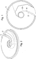
- the invention relates to a device for disintegrating food waste comprising bones using a rotating disc provided with an opening 2 in the disc and a knife 3 arranged by and along the opening 2.
- the edge of the knife is labeled 4.
- the cutting disc is mounted on a driven vertical axis 19, and the cutting disc is arranged in the lower part of a cylindrical housing in a conventional cutting machine for cutting vegetables. In the figures, such a conventional cutting machine is not shown.
- the cylindrical housing 18 is suggested in figure 3 .
- Food leftovers are intended to be fed down into the cylindrical house from above the cutting disc 1.
- the cutting disc rotates clockwise.
- the knife cuts through the food leftovers, whereby cut-off parts pass down through the opening 2 to a trough or the corresponding for feeding out of the cut-off pieces.
- a stationary stopping means 5 is mounted above the cutting disc 1, which extends from the center 6 of the cutting disc to the periphery 7 of the cutting disc.
- the stopping means 5 extends a certain distance upwards from the cutting disc 1, see figures 3 and 4 .
- the height of the stopping means may be 2 - 10 centimeters.
- the stopping means 5 has a stopping surface 8, which faces in a direction opposite to the rotational direction 9 of the cutting disc.
- An essential feature is that an angle V1 between the edge 4 of the knife 3 and the lower edge of the stopping surface 8 in a rotational position of the cutting disc, in which the edge 4 of the knife and the lower edge 12 of the stopping surface partly overlap, as seen in a direction perpendicularly to the plane of the cutting disc 1, opens inwards towards the center of the cutting disc 1.
- the cutting disc 1 is suitably made from stainless steel or aluminum.
- the knife 2 is made from steel.
- the stopping means may be made in a suitable known material, such as Teflon or another plastic material or a metal.
- the stopping means 5 may abut against the upper side of the cutting disc 1, but there may also be a certain distance between the underside of the stopping means and the upper side of the cutting disc. Such a distance should be smaller than the larges cross-sectional measure of said bone.
- the knife is curved with its inner 13 and outer 14 ends arranged further forward in the direction of motion of the cutting disc than the section 15 located between the ends.
- the knife 3 extends from a central sleeve 16 belonging to the cutting disc to a peripheral edge 17 of the cutting disc.
- the said stopping surface 8 is planar or essentially planar, and that it is radially or essentially radially positioned in relation to the cutting disc 1.
- the said stopping surface 8 slants, so that it forms an acute angle V2 in relation to the cutting disc 1 in a direction opposite to the direction 9 of motion of the cutting disc 1.
- the angle is 30 - 60 degrees.
- the vertical distance between the edge 4 of the knife and the upper surface of the cutting disc immediately in front of the knife is 2 - 4 millimeters, preferably 3 millimeters.
- the said opening 2 between the edge 4 of the knife and the edge 15 of the cutting disc at the opening is 2 - 4 millimeters, preferably 3 millimeters.
- stopping means 5 is fastened to the said cylindrical housing 18.
- the cutting disc 1 and the stopping means 5 are arranged to be mounted in a vegetable cutting machine of the mentioned type.
- the slanting stopping surface 8 of the stopping means in combination with the angle formed between the edge of the knife and the lower edge of the stopping means, results in that bones will not accumulate on top of the cutting disc, but will gradually be cut off and transported down through the opening of the cutting disc.
Landscapes
- Engineering & Computer Science (AREA)
- Food Science & Technology (AREA)
- Mechanical Engineering (AREA)
- Environmental & Geological Engineering (AREA)
- Food-Manufacturing Devices (AREA)
- Crushing And Pulverization Processes (AREA)
Description
- The present invention relates to a device for disintegrating food waste comprising bones. In catering kitchens and restaurants, large amounts of food waste are produced. These are usually separated during washing up. It is advantageous to disintegrate the leftovers and to feed these to a collecting tank. An advantageous way of transporting away the leftovers is to suck them up from out of the collecting tank and into a truck for removal.
- An increasingly more common way to take care of food leftovers is to transport these to a biogas plant, where the leftovers are transformed into biogas for use as vehicle propellant.
- In order to transport the food leftovers to the collecting tank, the leftovers must be disintegrated so that they can be transported in pipes without stoppage. This is particularly true as regards bones from birds, fish and also other types of bones, such as bones from meat chops. Moreover, it is advantageous for the biogas plant that the food leftovers are disintegrated.
- In order to disintegrate bones, mill grinders are known wherein two parts with projections exist, where each part has a projection with a space between two adjacent projections and where the parts are mutually displaced so that the projections on a first side pass between the spaces on a second side. Such mill grinders have strong motors, requiring electrical connection to three phases.
- However, such mill grinders are so costly so that an investment cannot be motivated when it comes to smaller catering kitchens, such as school kitchens and smaller restaurants. Hence, there is a need for a simpler and cheaper device for disintegrating food residuals.
- It is known to disintegrate raw food ingredients using kitchen appliances comprising a rotating cutting disc. These operate on the principle that the cutting disc is provided with an opening, by which a knife is mounted on the cutting disc. When the cutting disc rotates, the knife of the cutting disc cuts off a part of the raw ingredient, which thereafter passes down through the opening of the cutting disc down to a collecting vessel. Such a kitchen appliance normally requires only an electrical connection to one phase.
- It has turned out that bones are not always cut by such a cutting disc. This is of course a problem. Also, it gives rise to another problem, in that bone residues aggregate on top of the cutting disc. Document
WO-A-2010/013904 discloses a food waste shredder. The present invention solves the problem of disintegrating food leftovers including bones with a rotating cutting disc. Thereby, a kitchen appliance of the above type can be used, which means a considerably lower cost as compared to using a grinding mill of the above mentioned type. - Hence, the present invention relates to a device for disintegrating food waste, comprising bones, at a machine for cutting vegetables using a rotating disc provided with an opening in the disc and a knife arranged by and along the opening, which cutting disc is mounted on a driven vertical axis, and wherein the cutting disc is arranged in the lower part of a cylindrical housing into which food leftovers are arranged to be fed down from above the cutting disc, and is characterised in that a stationary stopping means is mounted above the cutting disc and from the center of the cutting disc to the periphery of the cutting disc, in that the stopping means extends a certain distance upwards from the cutting disc, in that the stopping means has a stopping surface, facing in a direction opposite to the direction of motion of the cutting disc, in that the angle between the edge of the knife and the stopping surface in a rotational position of the cutting disc, in which they partly overlap as seen in a direction perpendicularly to the plane of the cutting disc, opens inwards towards the center of the cutting disc, and in that the vertical distance between the edge of the knife and the underside of the stopping means allows cutting of bones, but is less than about 1 millimeters.
- Below, the invention is described in closer detail, partly in connection to an embodiment of the invention shown in the enclosed drawing, wherein
-
figure 1 shows a cutting disc from above -
figure 2 shows the cutting disc offigure 1 from below -
figure 3 shows the cutting disc from the side and a stopping means according to the invention -
figure 4 is a perspective view of the cutting disc and the stopping means -
figure 5 shows the cutting disc and the stopping means from above. - Hence, the invention relates to a device for disintegrating food waste comprising bones using a rotating disc provided with an
opening 2 in the disc and aknife 3 arranged by and along theopening 2. The edge of the knife is labeled 4. The cutting disc is mounted on a drivenvertical axis 19, and the cutting disc is arranged in the lower part of a cylindrical housing in a conventional cutting machine for cutting vegetables. In the figures, such a conventional cutting machine is not shown. Thecylindrical housing 18 is suggested infigure 3 . Food leftovers are intended to be fed down into the cylindrical house from above thecutting disc 1. Infigure 1 , the cutting disc rotates clockwise. During operation, the knife cuts through the food leftovers, whereby cut-off parts pass down through theopening 2 to a trough or the corresponding for feeding out of the cut-off pieces. - According to the invention, a stationary stopping means 5 is mounted above the
cutting disc 1, which extends from thecenter 6 of the cutting disc to theperiphery 7 of the cutting disc. The stopping means 5 extends a certain distance upwards from thecutting disc 1, seefigures 3 and 4 . The height of the stopping means may be 2 - 10 centimeters. - The stopping means 5 has a stopping
surface 8, which faces in a direction opposite to therotational direction 9 of the cutting disc. - An essential feature is that an angle V1 between the
edge 4 of theknife 3 and the lower edge of thestopping surface 8 in a rotational position of the cutting disc, in which theedge 4 of the knife and thelower edge 12 of the stopping surface partly overlap, as seen in a direction perpendicularly to the plane of thecutting disc 1, opens inwards towards the center of thecutting disc 1. - This is essential since the space between the edge of the knife and the said stopping surface will strive to displace bones inwards towards the center of the cutting disc, where the force for cutting through a bone increases the closer the bone is to the center of the cutting disc. That the knife edge is bent inwards towards the center of the cutting disc also contributes to that bones are more easily cut off.
- The
cutting disc 1 is suitably made from stainless steel or aluminum. Theknife 2 is made from steel. The stopping means may be made in a suitable known material, such as Teflon or another plastic material or a metal. - The stopping means 5 may abut against the upper side of the
cutting disc 1, but there may also be a certain distance between the underside of the stopping means and the upper side of the cutting disc. Such a distance should be smaller than the larges cross-sectional measure of said bone. - According to a preferred embodiment, the knife is curved with its inner 13 and outer 14 ends arranged further forward in the direction of motion of the cutting disc than the
section 15 located between the ends. - According to another preferred embodiment, the
knife 3 extends from acentral sleeve 16 belonging to the cutting disc to aperipheral edge 17 of the cutting disc. - It is preferred that the said stopping
surface 8 is planar or essentially planar, and that it is radially or essentially radially positioned in relation to thecutting disc 1. - Furthermore, it is preferred that the said stopping
surface 8 slants, so that it forms an acute angle V2 in relation to thecutting disc 1 in a direction opposite to thedirection 9 of motion of thecutting disc 1. - It is preferred that the angle is 30 - 60 degrees.
- There is a vertical distance between the
edge 4 of the knife and theunderside 10 of the stopping means of 0.5 - 1 millimeters. - It is preferred that the vertical distance between the
edge 4 of the knife and the upper surface of the cutting disc immediately in front of the knife is 2 - 4 millimeters, preferably 3 millimeters. - The said opening 2 between the
edge 4 of the knife and theedge 15 of the cutting disc at the opening is 2 - 4 millimeters, preferably 3 millimeters. - It is preferred that the stopping means 5 is fastened to the said
cylindrical housing 18. - The
cutting disc 1 and the stopping means 5 are arranged to be mounted in a vegetable cutting machine of the mentioned type. - The slanting
stopping surface 8 of the stopping means, in combination with the angle formed between the edge of the knife and the lower edge of the stopping means, results in that bones will not accumulate on top of the cutting disc, but will gradually be cut off and transported down through the opening of the cutting disc. - Hereby, the initially mentioned problem is solved.
- Above, a number of embodiments have been described. It is apparent that the stopping means can be given another detailed design while maintaining its function.
- Therefore, the present invention shall not be considered to be limited to the above given embodiments, but may be varied within the scope of the enclosed claims.
Claims (11)
- Device for disintegrating food waste, comprising bones, at a machine for cutting vegetables using a rotating disc (1) provided with an opening (2) in the disc and a knife (3) arranged by and along the opening (2), which cutting disc (1) is mounted on a driven vertical axis (19), and wherein the cutting disc is arranged in the lower part of a cylindrical housing (18) into which food leftovers are arranged to be fed down from above the cutting disc, characterised in that a stationary stopping means (5) is mounted above the cutting disc (1) and from the center (16) of the cutting disc to the periphery (17) of the cutting disc, in that the stopping means (5) extends a certain distance upwards from the cutting disc, in that the stopping means (5) has a stopping surface (8), facing in a direction opposite to the direction (9) of motion of the cutting disc, in that the angle (V1) between the edge (4) of the knife and the stopping surface (8) in a rotational position of the cutting disc (1), in which the edge (4) of the knife and the stopping surface (8) partly overlap as seen in a direction perpendicularly to the plane of the cutting disc (1), opens inwards towards the center (16) of the cutting disc, and in that the vertical distance between the edge of the knife and the underside of the stopping means allows cutting of bones, but is less than about 1 millimeters.
- Device according to claim 1, characterised in that the edge (4) of the knife (3) is curved with its inner (13) and outer (14) end further forward in the direction (9) of motion of the cutting disc than the section (15) located between the ends.
- Device according to claim 1 or 2, characterised in that the knife (4) extends from a central sleeve (16) belonging to the cutting disc to a peripheral edge (17) of the cutting disc.
- Device according to claim 1, 2 or 3, characterised in that the said stopping surface (8) is planar or essentially planar, and radially or essentially radially positioned relative to the cutting disc.
- Device according to claim 1, 2, 3 or 4, characterised in that the said stopping surface (8) slants so that it forms an acute angle (V2) in relation to the cutting disc (1) in a direction which is opposite to the direction (9) of motion of the cutting disc (9).
- Device according to claim 5, characterised in that the angle is 30 - 60 degrees.
- Device according to claim 1, 2, 3, 4, 5 or 6, characterised in that the said vertical distance between the edge (4) of the knife and the underside (10) of the stopping means is 0.5 - 1 millimeters.
- Device according to claim 1, 2, 3, 4, 5, 6 or 7, characterised in that the opening between the edge (4) of the knife and the edge (15) of the cutting disc at the opening is 2 - 4 millimeters, preferably 3 millimeters.
- Device according to claim 1, 2, 3, 4, 5, 6, 7 or 8, characterised in that the vertical distance between the edge (4) of the knife and the upper surface of the cutting disc immediately in front of the knife is 2 - 4 millimeters, preferably 3 millimeters.
- Device according to any one of the preceding claims, characterised in that the stopping means (5) is fastened to the said cylindrical housing (18).
- Device according to any one of the preceding claims, characterised in that the cutting disc (1) and the stopping means (5) are arranged to be mounted in a vegetable cutting machine of the mentioned type.
Applications Claiming Priority (2)
| Application Number | Priority Date | Filing Date | Title |
|---|---|---|---|
| SE1251229A SE536898C2 (en) | 2012-10-31 | 2012-10-31 | Device for atomizing food waste including bones. |
| PCT/SE2013/051254 WO2014070080A1 (en) | 2012-10-31 | 2013-10-25 | Device for disintegrating food waste comprising bones |
Publications (3)
| Publication Number | Publication Date |
|---|---|
| EP2914152A1 EP2914152A1 (en) | 2015-09-09 |
| EP2914152A4 EP2914152A4 (en) | 2016-06-01 |
| EP2914152B1 true EP2914152B1 (en) | 2017-07-12 |
Family
ID=50627809
Family Applications (1)
| Application Number | Title | Priority Date | Filing Date |
|---|---|---|---|
| EP13850321.4A Not-in-force EP2914152B1 (en) | 2012-10-31 | 2013-10-25 | Device for disintegrating food waste comprising bones |
Country Status (5)
| Country | Link |
|---|---|
| EP (1) | EP2914152B1 (en) |
| JP (1) | JP2016500568A (en) |
| CN (1) | CN103785512B (en) |
| SE (1) | SE536898C2 (en) |
| WO (1) | WO2014070080A1 (en) |
Families Citing this family (2)
| Publication number | Priority date | Publication date | Assignee | Title |
|---|---|---|---|---|
| CN104382505B (en) * | 2014-09-30 | 2017-01-25 | 牛伟民 | Bone pulp machine |
| RS57485B1 (en) * | 2016-05-27 | 2018-10-31 | Untha Shredding Tech Gmbh | Knife for a shredding machine |
Family Cites Families (14)
| Publication number | Priority date | Publication date | Assignee | Title |
|---|---|---|---|---|
| US4194697A (en) * | 1979-01-22 | 1980-03-25 | William Lembeck | Food processor and auxiliary mixing bowl therefor |
| DE3424427A1 (en) * | 1984-07-03 | 1986-01-09 | Immanuel 7000 Stuttgart Buck | Cutting knife |
| DE9115919U1 (en) * | 1991-12-21 | 1992-03-19 | Gloria-Werke H. Schulte-Frankenfeld Gmbh & Co, 4724 Wadersloh | Shredder with a knife disc attachment |
| DE9215679U1 (en) * | 1992-11-18 | 1994-04-21 | Telsnig, Adolf, 34125 Kassel | Choppers, especially for household and garden waste |
| JP2003112071A (en) * | 2001-10-04 | 2003-04-15 | Hirofumi Kurosaki | Food residue crusher |
| US7607599B2 (en) * | 2003-06-06 | 2009-10-27 | Emerson Electric Co. | Food waste reduction mechanism for disposer |
| CA2528212A1 (en) * | 2003-06-06 | 2004-12-16 | Emerson Electric Co. | Food waste reduction mechanism for disposer |
| WO2005105311A1 (en) * | 2004-04-26 | 2005-11-10 | Emerson Electric Co. | Food waste disposer shredder assembly |
| CN100475344C (en) * | 2006-11-29 | 2009-04-08 | 宁波阿勒法管系机械制造有限公司 | A crushing mechanism for food waste disposal |
| KR101017616B1 (en) * | 2008-07-28 | 2011-02-28 | 주식회사 매직카라 | Food waste disposer and its control method |
| CN101361638A (en) * | 2008-09-19 | 2009-02-11 | 漳州万利达光催化科技有限公司 | Tool for food processing machine |
| CN102451981B (en) * | 2010-10-29 | 2015-12-09 | 株式会社近畿 | The cutting edge that the manufacture method of cutting edge and the method manufacture |
| CN202097001U (en) * | 2011-05-12 | 2012-01-04 | 嘉兴溢联电子有限公司 | Crushing device of kitchen garbage treatment device |
| CN202129131U (en) * | 2011-06-21 | 2012-02-01 | 杭州铭湖机械有限公司 | Efficient crushing disk of kitchen food trash processor |
-
2012
- 2012-10-31 SE SE1251229A patent/SE536898C2/en not_active IP Right Cessation
-
2013
- 2013-07-02 CN CN201310271789.XA patent/CN103785512B/en not_active Expired - Fee Related
- 2013-10-25 EP EP13850321.4A patent/EP2914152B1/en not_active Not-in-force
- 2013-10-25 WO PCT/SE2013/051254 patent/WO2014070080A1/en not_active Ceased
- 2013-10-25 JP JP2015539557A patent/JP2016500568A/en active Pending
Non-Patent Citations (1)
| Title |
|---|
| None * |
Also Published As
| Publication number | Publication date |
|---|---|
| SE1251229A1 (en) | 2014-05-01 |
| SE536898C2 (en) | 2014-10-21 |
| EP2914152A1 (en) | 2015-09-09 |
| JP2016500568A (en) | 2016-01-14 |
| CN103785512B (en) | 2016-02-10 |
| CN103785512A (en) | 2014-05-14 |
| EP2914152A4 (en) | 2016-06-01 |
| WO2014070080A1 (en) | 2014-05-08 |
Similar Documents
| Publication | Publication Date | Title |
|---|---|---|
| EP2900113B1 (en) | Blade assembly for food processor and food processor incorporating same | |
| US9107539B2 (en) | Food processor | |
| US9254064B2 (en) | Apparatus for processing a food stuff | |
| US9770134B2 (en) | Apparatus and method for processing a food stuff | |
| RU2701617C2 (en) | Device for preparation of food ingredients | |
| WO2000001287A1 (en) | A cutting device for food processing machines | |
| EP3130264A2 (en) | Food processor with slice selector disc | |
| US20160135647A1 (en) | Device for the comminution of foodstuffs | |
| CN106572772A (en) | Blade assembly for a kitchen appliance and kitchen appliance having a blade assembly | |
| EP2615954B1 (en) | Knife for a cutting disc for a cutting machine | |
| EP2914152A1 (en) | Device for disintegrating food waste comprising bones | |
| EP2561780A1 (en) | A cutting disc for cutting foodstuffs and corresponding appliance | |
| CN220160133U (en) | Grinding mechanism of kitchen waste processor | |
| US3150701A (en) | Vegetable dicing machine | |
| CN214090170U (en) | Tearing mechanism of kitchen waste processor | |
| CN102995718A (en) | kitchen grinder | |
| EP3338605B1 (en) | Kitchen device | |
| JP2007190513A (en) | Garbage crushing apparatus | |
| KR20220000391U (en) | Plate for Rotating Crush | |
| KR20150123695A (en) | Food garbage disposing apparatus | |
| GB2495767A (en) | Food processing plate to redistribute comminuted foodstuffs | |
| HK1038484B (en) | A cutting device for food processing machines | |
| CN103394503A (en) | Commercial food waste processor |
Legal Events
| Date | Code | Title | Description |
|---|---|---|---|
| PUAI | Public reference made under article 153(3) epc to a published international application that has entered the european phase |
Free format text: ORIGINAL CODE: 0009012 |
|
| 17P | Request for examination filed |
Effective date: 20150601 |
|
| AK | Designated contracting states |
Kind code of ref document: A1 Designated state(s): AL AT BE BG CH CY CZ DE DK EE ES FI FR GB GR HR HU IE IS IT LI LT LU LV MC MK MT NL NO PL PT RO RS SE SI SK SM TR |
|
| AX | Request for extension of the european patent |
Extension state: BA ME |
|
| DAX | Request for extension of the european patent (deleted) | ||
| RA4 | Supplementary search report drawn up and despatched (corrected) |
Effective date: 20160429 |
|
| RIC1 | Information provided on ipc code assigned before grant |
Ipc: A47J 43/07 20060101AFI20160422BHEP Ipc: B02C 18/18 20060101ALI20160422BHEP |
|
| REG | Reference to a national code |
Ref country code: DE Ref legal event code: R079 Ref document number: 602013023567 Country of ref document: DE Free format text: PREVIOUS MAIN CLASS: A47J0043040000 Ipc: A47J0043070000 |
|
| GRAP | Despatch of communication of intention to grant a patent |
Free format text: ORIGINAL CODE: EPIDOSNIGR1 |
|
| RIC1 | Information provided on ipc code assigned before grant |
Ipc: B02C 18/18 20060101ALI20170116BHEP Ipc: A47J 43/07 20060101AFI20170116BHEP |
|
| INTG | Intention to grant announced |
Effective date: 20170207 |
|
| RIN1 | Information on inventor provided before grant (corrected) |
Inventor name: EKSTROEM, ULF |
|
| GRAS | Grant fee paid |
Free format text: ORIGINAL CODE: EPIDOSNIGR3 |
|
| GRAA | (expected) grant |
Free format text: ORIGINAL CODE: 0009210 |
|
| AK | Designated contracting states |
Kind code of ref document: B1 Designated state(s): AL AT BE BG CH CY CZ DE DK EE ES FI FR GB GR HR HU IE IS IT LI LT LU LV MC MK MT NL NO PL PT RO RS SE SI SK SM TR |
|
| REG | Reference to a national code |
Ref country code: GB Ref legal event code: FG4D |
|
| REG | Reference to a national code |
Ref country code: CH Ref legal event code: EP |
|
| REG | Reference to a national code |
Ref country code: AT Ref legal event code: REF Ref document number: 907539 Country of ref document: AT Kind code of ref document: T Effective date: 20170715 |
|
| REG | Reference to a national code |
Ref country code: IE Ref legal event code: FG4D |
|
| REG | Reference to a national code |
Ref country code: DE Ref legal event code: R096 Ref document number: 602013023567 Country of ref document: DE |
|
| REG | Reference to a national code |
Ref country code: FR Ref legal event code: PLFP Year of fee payment: 5 |
|
| REG | Reference to a national code |
Ref country code: NL Ref legal event code: MP Effective date: 20170712 |
|
| REG | Reference to a national code |
Ref country code: LT Ref legal event code: MG4D |
|
| REG | Reference to a national code |
Ref country code: AT Ref legal event code: MK05 Ref document number: 907539 Country of ref document: AT Kind code of ref document: T Effective date: 20170712 |
|
| PG25 | Lapsed in a contracting state [announced via postgrant information from national office to epo] |
Ref country code: FI Free format text: LAPSE BECAUSE OF FAILURE TO SUBMIT A TRANSLATION OF THE DESCRIPTION OR TO PAY THE FEE WITHIN THE PRESCRIBED TIME-LIMIT Effective date: 20170712 Ref country code: NO Free format text: LAPSE BECAUSE OF FAILURE TO SUBMIT A TRANSLATION OF THE DESCRIPTION OR TO PAY THE FEE WITHIN THE PRESCRIBED TIME-LIMIT Effective date: 20171012 Ref country code: AT Free format text: LAPSE BECAUSE OF FAILURE TO SUBMIT A TRANSLATION OF THE DESCRIPTION OR TO PAY THE FEE WITHIN THE PRESCRIBED TIME-LIMIT Effective date: 20170712 Ref country code: LT Free format text: LAPSE BECAUSE OF FAILURE TO SUBMIT A TRANSLATION OF THE DESCRIPTION OR TO PAY THE FEE WITHIN THE PRESCRIBED TIME-LIMIT Effective date: 20170712 Ref country code: NL Free format text: LAPSE BECAUSE OF FAILURE TO SUBMIT A TRANSLATION OF THE DESCRIPTION OR TO PAY THE FEE WITHIN THE PRESCRIBED TIME-LIMIT Effective date: 20170712 Ref country code: HR Free format text: LAPSE BECAUSE OF FAILURE TO SUBMIT A TRANSLATION OF THE DESCRIPTION OR TO PAY THE FEE WITHIN THE PRESCRIBED TIME-LIMIT Effective date: 20170712 Ref country code: SE Free format text: LAPSE BECAUSE OF FAILURE TO SUBMIT A TRANSLATION OF THE DESCRIPTION OR TO PAY THE FEE WITHIN THE PRESCRIBED TIME-LIMIT Effective date: 20170712 |
|
| PG25 | Lapsed in a contracting state [announced via postgrant information from national office to epo] |
Ref country code: BG Free format text: LAPSE BECAUSE OF FAILURE TO SUBMIT A TRANSLATION OF THE DESCRIPTION OR TO PAY THE FEE WITHIN THE PRESCRIBED TIME-LIMIT Effective date: 20171012 Ref country code: LV Free format text: LAPSE BECAUSE OF FAILURE TO SUBMIT A TRANSLATION OF THE DESCRIPTION OR TO PAY THE FEE WITHIN THE PRESCRIBED TIME-LIMIT Effective date: 20170712 Ref country code: RS Free format text: LAPSE BECAUSE OF FAILURE TO SUBMIT A TRANSLATION OF THE DESCRIPTION OR TO PAY THE FEE WITHIN THE PRESCRIBED TIME-LIMIT Effective date: 20170712 Ref country code: PL Free format text: LAPSE BECAUSE OF FAILURE TO SUBMIT A TRANSLATION OF THE DESCRIPTION OR TO PAY THE FEE WITHIN THE PRESCRIBED TIME-LIMIT Effective date: 20170712 Ref country code: ES Free format text: LAPSE BECAUSE OF FAILURE TO SUBMIT A TRANSLATION OF THE DESCRIPTION OR TO PAY THE FEE WITHIN THE PRESCRIBED TIME-LIMIT Effective date: 20170712 Ref country code: GR Free format text: LAPSE BECAUSE OF FAILURE TO SUBMIT A TRANSLATION OF THE DESCRIPTION OR TO PAY THE FEE WITHIN THE PRESCRIBED TIME-LIMIT Effective date: 20171013 Ref country code: IS Free format text: LAPSE BECAUSE OF FAILURE TO SUBMIT A TRANSLATION OF THE DESCRIPTION OR TO PAY THE FEE WITHIN THE PRESCRIBED TIME-LIMIT Effective date: 20171112 |
|
| REG | Reference to a national code |
Ref country code: DE Ref legal event code: R097 Ref document number: 602013023567 Country of ref document: DE |
|
| PG25 | Lapsed in a contracting state [announced via postgrant information from national office to epo] |
Ref country code: CZ Free format text: LAPSE BECAUSE OF FAILURE TO SUBMIT A TRANSLATION OF THE DESCRIPTION OR TO PAY THE FEE WITHIN THE PRESCRIBED TIME-LIMIT Effective date: 20170712 Ref country code: RO Free format text: LAPSE BECAUSE OF FAILURE TO SUBMIT A TRANSLATION OF THE DESCRIPTION OR TO PAY THE FEE WITHIN THE PRESCRIBED TIME-LIMIT Effective date: 20170712 Ref country code: DK Free format text: LAPSE BECAUSE OF FAILURE TO SUBMIT A TRANSLATION OF THE DESCRIPTION OR TO PAY THE FEE WITHIN THE PRESCRIBED TIME-LIMIT Effective date: 20170712 |
|
| PLBE | No opposition filed within time limit |
Free format text: ORIGINAL CODE: 0009261 |
|
| STAA | Information on the status of an ep patent application or granted ep patent |
Free format text: STATUS: NO OPPOSITION FILED WITHIN TIME LIMIT |
|
| PG25 | Lapsed in a contracting state [announced via postgrant information from national office to epo] |
Ref country code: IT Free format text: LAPSE BECAUSE OF FAILURE TO SUBMIT A TRANSLATION OF THE DESCRIPTION OR TO PAY THE FEE WITHIN THE PRESCRIBED TIME-LIMIT Effective date: 20170712 Ref country code: SK Free format text: LAPSE BECAUSE OF FAILURE TO SUBMIT A TRANSLATION OF THE DESCRIPTION OR TO PAY THE FEE WITHIN THE PRESCRIBED TIME-LIMIT Effective date: 20170712 Ref country code: SM Free format text: LAPSE BECAUSE OF FAILURE TO SUBMIT A TRANSLATION OF THE DESCRIPTION OR TO PAY THE FEE WITHIN THE PRESCRIBED TIME-LIMIT Effective date: 20170712 Ref country code: EE Free format text: LAPSE BECAUSE OF FAILURE TO SUBMIT A TRANSLATION OF THE DESCRIPTION OR TO PAY THE FEE WITHIN THE PRESCRIBED TIME-LIMIT Effective date: 20170712 Ref country code: MC Free format text: LAPSE BECAUSE OF FAILURE TO SUBMIT A TRANSLATION OF THE DESCRIPTION OR TO PAY THE FEE WITHIN THE PRESCRIBED TIME-LIMIT Effective date: 20170712 |
|
| REG | Reference to a national code |
Ref country code: CH Ref legal event code: PL |
|
| 26N | No opposition filed |
Effective date: 20180413 |
|
| REG | Reference to a national code |
Ref country code: IE Ref legal event code: MM4A |
|
| PG25 | Lapsed in a contracting state [announced via postgrant information from national office to epo] |
Ref country code: CH Free format text: LAPSE BECAUSE OF NON-PAYMENT OF DUE FEES Effective date: 20171031 Ref country code: LI Free format text: LAPSE BECAUSE OF NON-PAYMENT OF DUE FEES Effective date: 20171031 Ref country code: LU Free format text: LAPSE BECAUSE OF NON-PAYMENT OF DUE FEES Effective date: 20171025 |
|
| REG | Reference to a national code |
Ref country code: BE Ref legal event code: MM Effective date: 20171031 |
|
| PG25 | Lapsed in a contracting state [announced via postgrant information from national office to epo] |
Ref country code: BE Free format text: LAPSE BECAUSE OF NON-PAYMENT OF DUE FEES Effective date: 20171031 Ref country code: SI Free format text: LAPSE BECAUSE OF FAILURE TO SUBMIT A TRANSLATION OF THE DESCRIPTION OR TO PAY THE FEE WITHIN THE PRESCRIBED TIME-LIMIT Effective date: 20170712 |
|
| PG25 | Lapsed in a contracting state [announced via postgrant information from national office to epo] |
Ref country code: MT Free format text: LAPSE BECAUSE OF NON-PAYMENT OF DUE FEES Effective date: 20171025 |
|
| REG | Reference to a national code |
Ref country code: FR Ref legal event code: PLFP Year of fee payment: 6 |
|
| PG25 | Lapsed in a contracting state [announced via postgrant information from national office to epo] |
Ref country code: IE Free format text: LAPSE BECAUSE OF NON-PAYMENT OF DUE FEES Effective date: 20171025 |
|
| PG25 | Lapsed in a contracting state [announced via postgrant information from national office to epo] |
Ref country code: HU Free format text: LAPSE BECAUSE OF FAILURE TO SUBMIT A TRANSLATION OF THE DESCRIPTION OR TO PAY THE FEE WITHIN THE PRESCRIBED TIME-LIMIT; INVALID AB INITIO Effective date: 20131025 |
|
| PG25 | Lapsed in a contracting state [announced via postgrant information from national office to epo] |
Ref country code: CY Free format text: LAPSE BECAUSE OF FAILURE TO SUBMIT A TRANSLATION OF THE DESCRIPTION OR TO PAY THE FEE WITHIN THE PRESCRIBED TIME-LIMIT Effective date: 20170712 |
|
| PG25 | Lapsed in a contracting state [announced via postgrant information from national office to epo] |
Ref country code: MK Free format text: LAPSE BECAUSE OF FAILURE TO SUBMIT A TRANSLATION OF THE DESCRIPTION OR TO PAY THE FEE WITHIN THE PRESCRIBED TIME-LIMIT Effective date: 20170712 |
|
| PG25 | Lapsed in a contracting state [announced via postgrant information from national office to epo] |
Ref country code: TR Free format text: LAPSE BECAUSE OF FAILURE TO SUBMIT A TRANSLATION OF THE DESCRIPTION OR TO PAY THE FEE WITHIN THE PRESCRIBED TIME-LIMIT Effective date: 20170712 |
|
| PG25 | Lapsed in a contracting state [announced via postgrant information from national office to epo] |
Ref country code: PT Free format text: LAPSE BECAUSE OF FAILURE TO SUBMIT A TRANSLATION OF THE DESCRIPTION OR TO PAY THE FEE WITHIN THE PRESCRIBED TIME-LIMIT Effective date: 20170712 |
|
| PG25 | Lapsed in a contracting state [announced via postgrant information from national office to epo] |
Ref country code: AL Free format text: LAPSE BECAUSE OF FAILURE TO SUBMIT A TRANSLATION OF THE DESCRIPTION OR TO PAY THE FEE WITHIN THE PRESCRIBED TIME-LIMIT Effective date: 20170712 |
|
| PGFP | Annual fee paid to national office [announced via postgrant information from national office to epo] |
Ref country code: DE Payment date: 20201021 Year of fee payment: 8 Ref country code: GB Payment date: 20201020 Year of fee payment: 8 Ref country code: FR Payment date: 20201020 Year of fee payment: 8 |
|
| REG | Reference to a national code |
Ref country code: DE Ref legal event code: R119 Ref document number: 602013023567 Country of ref document: DE |
|
| GBPC | Gb: european patent ceased through non-payment of renewal fee |
Effective date: 20211025 |
|
| PG25 | Lapsed in a contracting state [announced via postgrant information from national office to epo] |
Ref country code: GB Free format text: LAPSE BECAUSE OF NON-PAYMENT OF DUE FEES Effective date: 20211025 Ref country code: DE Free format text: LAPSE BECAUSE OF NON-PAYMENT OF DUE FEES Effective date: 20220503 |
|
| PG25 | Lapsed in a contracting state [announced via postgrant information from national office to epo] |
Ref country code: FR Free format text: LAPSE BECAUSE OF NON-PAYMENT OF DUE FEES Effective date: 20211031 |