EP2914017A1 - Speaker module - Google Patents
Speaker module Download PDFInfo
- Publication number
- EP2914017A1 EP2914017A1 EP15156036.4A EP15156036A EP2914017A1 EP 2914017 A1 EP2914017 A1 EP 2914017A1 EP 15156036 A EP15156036 A EP 15156036A EP 2914017 A1 EP2914017 A1 EP 2914017A1
- Authority
- EP
- European Patent Office
- Prior art keywords
- air flowing
- air
- main body
- speaker module
- space
- Prior art date
- Legal status (The legal status is an assumption and is not a legal conclusion. Google has not performed a legal analysis and makes no representation as to the accuracy of the status listed.)
- Granted
Links
Images




Classifications
-
- H—ELECTRICITY
- H04—ELECTRIC COMMUNICATION TECHNIQUE
- H04R—LOUDSPEAKERS, MICROPHONES, GRAMOPHONE PICK-UPS OR LIKE ACOUSTIC ELECTROMECHANICAL TRANSDUCERS; ELECTRIC HEARING AIDS; PUBLIC ADDRESS SYSTEMS
- H04R1/00—Details of transducers, loudspeakers or microphones
- H04R1/20—Arrangements for obtaining desired frequency or directional characteristics
- H04R1/22—Arrangements for obtaining desired frequency or directional characteristics for obtaining desired frequency characteristic only
- H04R1/28—Transducer mountings or enclosures modified by provision of mechanical or acoustic impedances, e.g. resonator, damping means
- H04R1/2807—Enclosures comprising vibrating or resonating arrangements
-
- H—ELECTRICITY
- H04—ELECTRIC COMMUNICATION TECHNIQUE
- H04R—LOUDSPEAKERS, MICROPHONES, GRAMOPHONE PICK-UPS OR LIKE ACOUSTIC ELECTROMECHANICAL TRANSDUCERS; ELECTRIC HEARING AIDS; PUBLIC ADDRESS SYSTEMS
- H04R1/00—Details of transducers, loudspeakers or microphones
- H04R1/20—Arrangements for obtaining desired frequency or directional characteristics
- H04R1/22—Arrangements for obtaining desired frequency or directional characteristics for obtaining desired frequency characteristic only
- H04R1/28—Transducer mountings or enclosures modified by provision of mechanical or acoustic impedances, e.g. resonator, damping means
- H04R1/2807—Enclosures comprising vibrating or resonating arrangements
- H04R1/2815—Enclosures comprising vibrating or resonating arrangements of the bass reflex type
- H04R1/2823—Vents, i.e. ports, e.g. shape thereof or tuning thereof with damping material
Definitions
- the disclosure relates to a speaker module, and more particularly, to a speaker module having a good sound quality.
- a speaker unit of a speaker module is driven by audio source signals, and generates resonance with the air molecules in the resonance space of the main body, so as to output sound wave signals out of the sound outlet opening of the main body.
- the resonance space is a hermetically sealed space, during transportation process, then the air pressure in the resonance space may not be regulated with the change of environment.
- the atmospheric pressure of the outside may be lower than the air pressure in the resonance space; when the speaker module is transported to the factory for assembling, the atmospheric pressure of the assembling environment may substantially be the same as the air pressure in the resonance space.
- the atmospheric pressure at where the speaker module is located may change with different environments.
- the disclosure provides a speaker module with favorable sound quality.
- a speaker module of the disclosure includes a speaker unit, a main body and a speaker carrier.
- the main body has a sound outlet opening.
- the sound outlet opening is configured to expose the speaker unit.
- the speaker carrier is configured to carry the speaker unit.
- the speaker carrier is disposed in the main body together with the speaker unit, and forms a resonance space with the main body.
- the main body includes an air pressure regulating structure.
- the air pressure regulating structure is configured to regulate the air pressure of the resonance space.
- the main body includes a surrounding wall and a bottom wall.
- the speaker carrier, the surrounding wall and the bottom wall together define the resonance space.
- the bottom wall is disposed opposite to the sound outlet opening, and the air pressure regulating structure is disposed at the bottom wall.
- the bottom wall includes a stepped structure.
- the air pressure regulating structure is disposed on the stepped structure of the bottom wall.
- the speaker module further includes a covering thin body.
- the covering thin body is configured to partially cover the air pressure regulating structure, so as to expose a portion of the air pressure regulating structure.
- the air in the resonance space flows out of the main body through the portion of the air pressure regulation structure which is exposed.
- the air pressure regulating structure includes a first air flowing channel.
- the first air flowing channel extends in a first direction, configured to connect the resonance space.
- the first air flowing channel includes a first channel hole. The air in the resonance space flows out of the main body through the first air flowing channel and the first channel hole.
- the area of a cross section of the first air flowing channel in the first direction is smaller than a first threshold area value.
- the cross section of the first air flowing channel is a circle, an ellipse or a polygon.
- an extending length of the first air flowing channel in the first direction is larger than a first threshold length value.
- the first direction is substantially parallel to a normal vector of a surface of the main body.
- the air pressure regulating structure further includes an air flowing space.
- the air flowing space expands on the surface of the main body and is configured to connect the first air flowing channel and the resonance space.
- the air in the resonance space flows out of the main body through the air flowing space, the first air flowing channel and the first channel hole.
- the area of a cross section of the air flowing space in the first direction is larger than a second threshold area value.
- the cross section of the air flowing space is a circle, an ellipse or a polygon.
- a depth of the air flowing space in the first direction is larger than a first threshold depth value.
- the first direction is substantially parallel to a normal vector of the surface of the main body.
- the air pressure regulating structure includes a second air flowing channel.
- the second air flowing channel extends in a second direction, configured to connecting the air flowing space and the resonance space.
- the second air flowing channel includes a second channel hole. The air in the resonance space flows out of the main body through the second channel hole, the second air flowing channel, the air flowing space, the first air flowing channel and the first channel hole.
- the area of a cross section of the second air flowing channel in the second direction is larger than a third threshold area value.
- the cross section of the first air flowing channel is a circle, an ellipse or a polygon.
- the cross section of the first air flowing channel is a portion of the circle, a portion of the ellipse or a portion of the polygon.
- an extending length of the second air flowing channel in the second direction is larger than a second threshold length value.
- a depth of the second air flowing channel in the first direction is smaller than a second threshold depth value.
- the surrounding wall includes a pair of parallel long walls, and the second direction is substantially parallel to an extending direction of the pair of parallel long walls.
- the air pressure regulating structure of the main body may be configured to regulate the air pressure in the resonance space.
- noise signal of the speaker module may be reduced, and a good sound quality is maintained.
- FIG. 1 is a schematic view illustrating a speaker module according to an embodiment of the disclosure.
- the speaker module 100 of the embodiment includes a speaker unit 110 and a main body 120.
- the main body 120 includes an air pressure regulating structure 130.
- the internal walls of the main body 120 form a resonance space S.
- the speaker unit 110 is driven by audio source signals, and generates resonance with the air molecules in the resonance space S, so as to output sound wave signals out of a sound outlet opening 122 of the main body 120.
- the resonance space S is a hermetically sealed space, during transportation process of the speaker module 100, the air pressure in the resonance space S may not be regulated with the change of the environment.
- the resonance space S may communicate with external environment, thus the air molecules within the resonance space S may flow out of the main body 120, and the air molecules from the outside may also flow into the resonance space S. Therefore, the air pressure regulating structure 130 may be configured to regulate the air pressure of the resonance space S.
- FIG. 2 is a schematic view illustrating air molecules flow in two different communicating spaces.
- the cross section area of the first communicating space S1 is larger than the cross section area of the second communicating space S2, thus when the air molecules flow from the first communicating space S1 to the second communicating space S2, the moving speed of the air molecules may become faster.
- the moving space of the air molecules may become slower.
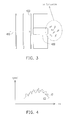
- FIG. 3 is a schematic view illustrating air molecules are transmitted from the left space to the right space through the air flowing channel. Please refer to FIG. 3 , the air molecules move toward the right space through the air flowing channel 430 along the speed direction 410, and the label 420 represents the wavefront of the sound wave corresponding to the air molecules. According to illustration of Bernoulli's Theorem, when the air molecules are transmitted to the right space through the air flowing channel 430, air turbulence may be generated.
- FIG. 4 is a relationship diagram showing moving speed of the air molecules change with time. Please refer to FIG. 4 , in FIG. 4 , the speed curve C1 represents the relationship illustrating the moving speed changes with time when the air molecules generate air turbulence.
- the speed curve C1 may appear to be abnormally tortuous and quivering, noise signals may be generated when the speaker unit 110 makes a sound, and the sound quality is reduced.
- the speed curve C2 represents the relationship illustrating the moving speed changes with time after the acoustic impedance of air is regulated.
- the speed curve C2 may appear to be comparatively smoother, representing noise signals may be comparatively lower when the speaker unit 110 of the embodiment makes a sound, and the sound quality is good.
- the design of the air pressure regulating structure of the disclosure is illustrated with reference of at least one exemplary embodiment as follows. However, the disclosure is not limited to the described embodiment, and the embodiment may have suitable change.
- FIG. 5 and FIG. 6 are schematic views illustrating a speaker module in different viewing angles according to another embodiment of the disclosure.
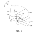
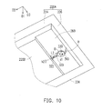
- FIG. 7, FIG. 8 , FIG. 9 and FIG. 10 are schematic views illustrating the internal structure of the speaker module of FIG. 5 and FIG. 6 corresponding to different cross section lines.
- the speaker module 200 of the embodiment includes a speaker unit 210, a main body 220, a speaker carrier 240 and a covering thin body 250.
- the main body 220 includes a sound outlet opening 222 and an air pressure regulating structure 230.
- the sound outlet opening 222 is configured to expose the speaker unit 210.
- the speaker carrier 240 is configured to carry the speaker unit 210.
- the speaker carrier 240 and the speaker unit 210 are disposed together in the main body 220.
- the speaker carrier 240 and the main body 220 form a resonance space S3.
- the speaker unit 210 is driven by audio source signals, and generates resonance with the air molecules in the resonance space S3, so as to output sound wave signals out of the sound outlet opening 222 of the main body 220.
- the outer appearance of the main body 220 of the embodiment is exemplarily illustrated as a cuboid, but the disclosure is not limited thereto. In other embodiments, the outer appearance of the main body 220 may have any other suitable stereoscopic geometrical profile.
- the main body 220 includes a surrounding wall 220A and a bottom wall 220B.
- the bottom wall 220B of the embodiment is disposed opposite to the main body 222 in the first direction D1.
- the bottom wall 220B includes a stepped structure 260.
- the stepped structure 260 is selectively disposed, in other embodiments, the bottom wall 220B may not include the stepped structure 260, at this time, the surface of the bottom wall 220B in the main body 220 is smooth and without a step.
- the surrounding wall 220A of the embodiment includes a pair of parallel long walls 224 and a pair of parallel short walls 226.
- the parallel long walls 224 extend in the second direction D2, and arranged in the third direction D3.
- the parallel short walls 226 extend in the third direction D3, and arranged in the second direction D2.
- three of the speaker carrier 240, the surrounding wall 220A and the bottom wall 220B together define the resonance space S3.
- the air pressure regulating structure 230 is disposed on the stepped structure 260 of the bottom wall 220B.
- the covering thin body 250 is configured to partially cover the air pressure regulating structure 230, in order to expose a portion of the air pressure regulating structure 230, so that the air in the resonance space S3 flow out of the main body 220 through a portion of the air pressure regulating structure 230 which is exposed, so as to achieve the purpose of regulating the air pressure in the resonance space S3.
- a portion of the exposed air pressure regulating structure 230 may be a second channel hole 322 of the air pressure regulating structure 230, for example.
- the air in the resonance space S3 may at least flow out of the main body 220 through the second channel hole 322, on the contrary, the air outside the resonance space S3 may flow into the main body 220 through the first channel hole 312, so as to balance the air pressure inside and outside the resonance space S3.
- the air pressure regulating structure 230 is disposed on the stepped structure 260 of the bottom wall 220B, the disclosure is not limited thereto.
- the air pressure regulating structure 230 may also be directly disposed on any position of the bottom wall 220B.
- the air pressure regulating structure 230 is not limited to be disposed on the bottom wall 220B, in other embodiments, the air pressure regulating structure 230 may also be disposed on the surrounding wall 220A of the main body 220, namely, the disposing position of the air pressure regulating structure 230 is not limited in the disclosure.
- the covering thin body 250 is a flexible material, for example, but not limited to be a thin film of metal or plastic material, such as polyester film.
- the air pressure regulating structure 230 includes a first air flowing channel 310, an air flowing space 330 and a second air flowing channel 320.
- the air in the resonance space S3 may flow out of the main body 220 through the second channel hole 322, the second air flowing channel 320, the air flowing space 330, the first air flowing channel 310 and the first channel hole 312.
- the air outside the resonance space S3 may flow into the main body 220 through the first channel hole 312, the first air flowing channel 310, the air flowing space 330, the second air flowing channel 320, and the second channel hole 322, so as to balance the air pressure inside and outside the resonance space S3.
- the first air flowing channel 310 extends in the first direction D1, and connected with the outside of the main body through the first channel hole 312.
- the second air flowing channel 320 extends in the second direction D2, and connected with the resonance space S3 of the inside of the main body 220 through the second channel hole 322.
- the first direction D1 is substantially perpendicular to the second direction D2, namely, the first air flowing channel 310 is substantially perpendicular to the second air flowing channel 320, however the disclosure is not limited thereto.
- the first air flowing channel 310 and the second air flowing channel 322 may not be perpendicular to each other.
- the first air flowing channel 310 substantially perpendicularly penetrates from the surface of the bottom wall 220B of the main body 220 which is facing the surface of the resonance space S3 to the outside of the main body 220 along the first direction D1, but the disclosure is not limited thereto.
- the first air flowing channel 310 may also penetrate from the surface of the bottom 220B to the outside of the main body 220 along an inclined direction. An acute included angle which is less than 90 degrees is between the inclined direction and the first direction, for example.
- the cross section of the first air flowing channel 310 in the first direction D1 is a circle, but the disclosure is not limited thereto.
- the cross section of the first air flowing channel 310 in the first direction D1 may also be an ellipse or a polygon.
- the polygon includes, but not limited to, polygon such as a triangle, a square, a rectangle, a rhombus, a trapezium, a pentagon, a hexagon, and so on.
- the second air flowing channel 320 extends in the second direction D2, namely, the extending direction of the second air flowing channel 320 is substantially parallel to the extending direction of the parallel long walls 224, however the disclosure is not limited thereto.
- the extending direction of the second air flowing channel 320 and extending direction of the parallel long walls 224 may not be parallel to each other.
- an included angle is between the extending direction of the second air flowing channel 320 and the second direction D2, for example.
- the included angle may be an acute angle, a right angle or an obtuse angle.
- the cross section of the second air flowing channel 320 in the second direction D2 is a rectangle, for example, but the disclosure is not limited thereto.
- the cross section of the second air flowing channel 320 in the second direction D2 may also be a circle, an ellipse or other polygon.
- the polygon includes, but not limited to, polygon such as a triangle, a square, a rhombus, a trapezium, a pentagon, a hexagon, and so on.
- the cross section of the second air flowing channel 320 in the second direction D2 of the disclosure may also be a portion of the circle, a portion of the ellipse or a portion of the polygon, but the disclosure is not limited thereto.
- the air flowing space 330 expands on the surface of the bottom wall 220B of the main body 220 which is facing the surface of the resonance space S3, configured to connect the first air flowing channel 330, the second air flowing channel 320 and the resonance space S3.
- the cross section of the air flowing space in the first direction D1 is a circle, for example, but the disclosure is not limited thereto.
- the cross section of the air flowing space 330 in the first direction D1 may also be an ellipse or a polygon.
- the polygon includes, but not limited to, polygon such as a triangle, a square, a rectangle, a rhombus, a trapezium, a pentagon, a hexagon, and so on.
- the acoustic impedance of air the air molecules encounter may be regulated, and the effect of the air turbulence to the sound quality may be reduced.
- the effect of noise signals of a specific band on the sound quality may be reduced.
- the area of the cross section of the first air flowing channel 310 in the first direction D1. is smaller than a first threshold area value in the embodiment, for example.
- a first threshold area value for example.
- the diameter d1 of the first channel hole 312 of the first air flowing channel 310 is smaller than a first diameter threshold value, for example d1 ⁇ 0.2 mm (millimeter).
- the extending length L1 of the first air flowing channel 310 in the first direction D1 is larger than a first threshold length value.
- the area of the cross section of the air flowing space 330 in the first direction D1 is larger than a second threshold area value.
- a second diameter threshold value for example D > 0.4 mm (millimeter).
- the depth H of the air flowing space 330 in the first direction D1 is larger than a first threshold depth value in the embodiment, for example.
- the area of the cross section of the second air flowing channel 320 in the second direction D2 is larger than a third threshold area value, for example.
- a third threshold area value for example.
- the depth h2 of the second air flowing channel 320 in the first direction D1 is smaller than a second threshold depth value, for example h2 ⁇ 0.15 mm.
- the extending length L2 of the second air flowing channel 320 in the second direction D2 is larger than a second threshold length value, for example L2 > 1.4 mm.
- FIG. 11 is a curve relationship illustrating the effect of noise signal of a specific band on the sound quality according to an embodiment of the disclosure.
- the sound quality curve C3 appears to be comparatively smoother, compared to the sound quality curves C4, C5 of other embodiments, the noise signals of the speaker module 220 is lower when making a sound, the sound quality is good.
- the covering thin body 250, the stepped structure 260 of the bottom wall 220B, and the first air flowing channel 310, the air flowing space 330 and the second air flowing channel 320 of the air pressure regulating structure 230 of the speaker module 200 may all be designed as actual requirements or selectively disposed according to the frequency band of which the noise signals are desired to be reduced, the disclosure is not limited thereto.
- the air pressure regulating structure 230 may only include one of the three, or two of the three, or all of the three, as the same as the air pressure regulating structure 230 of the embodiment shown in FIG. 5 to FIG. 10 , of the first air flowing channel 310, the air flowing space 330 and the second air flowing channel 320.
- the air pressure regulating structure of the main body may be configured to regulate the air pressure in the resonance space.
- the air pressure regulating structure Through appropriate design of the air pressure regulating structure, at least the effect of the air turbulence on the sound quality of the speaker module may be reduced, and noise signals may be reduced, and a good sound quality is maintained.
- the effect of the noise signals of the specific band to the sound quality may also be reduced.
Landscapes
- Health & Medical Sciences (AREA)
- Otolaryngology (AREA)
- Physics & Mathematics (AREA)
- Engineering & Computer Science (AREA)
- Acoustics & Sound (AREA)
- Signal Processing (AREA)
- Details Of Audible-Bandwidth Transducers (AREA)
Abstract
Description
- This application claims the priority benefits of
U.S. provisional application serial no. 61/945,093, filed on February 26, 2014 - The disclosure relates to a speaker module, and more particularly, to a speaker module having a good sound quality.
- In general, a speaker unit of a speaker module is driven by audio source signals, and generates resonance with the air molecules in the resonance space of the main body, so as to output sound wave signals out of the sound outlet opening of the main body. However, after fabrication of the speaker module is completed, if the resonance space is a hermetically sealed space, during transportation process, then the air pressure in the resonance space may not be regulated with the change of environment. For example, when the speaker module is transported by using an aircraft, the atmospheric pressure of the outside may be lower than the air pressure in the resonance space; when the speaker module is transported to the factory for assembling, the atmospheric pressure of the assembling environment may substantially be the same as the air pressure in the resonance space. Thus, the atmospheric pressure at where the speaker module is located may change with different environments. However, if the air pressure in the resonance space is unable to be regulated with the change of environment, the sound quality of when the speaker module outputs sound wave signals may easily be affected. Therefore, how to design a speaker module having sound quality and transportation cost benefit has become an important issue.
- The disclosure provides a speaker module with favorable sound quality.
- A speaker module of the disclosure includes a speaker unit, a main body and a speaker carrier. The main body has a sound outlet opening. The sound outlet opening is configured to expose the speaker unit. The speaker carrier is configured to carry the speaker unit. The speaker carrier is disposed in the main body together with the speaker unit, and forms a resonance space with the main body. The main body includes an air pressure regulating structure. The air pressure regulating structure is configured to regulate the air pressure of the resonance space.
- According to an exemplary embodiment of the disclosure, the main body includes a surrounding wall and a bottom wall. The speaker carrier, the surrounding wall and the bottom wall together define the resonance space. The bottom wall is disposed opposite to the sound outlet opening, and the air pressure regulating structure is disposed at the bottom wall.
- According to an exemplary embodiment of the disclosure, the bottom wall includes a stepped structure. The air pressure regulating structure is disposed on the stepped structure of the bottom wall.
- According to an exemplary embodiment of the disclosure, the speaker module further includes a covering thin body. The covering thin body is configured to partially cover the air pressure regulating structure, so as to expose a portion of the air pressure regulating structure. The air in the resonance space flows out of the main body through the portion of the air pressure regulation structure which is exposed.
- According to an exemplary embodiment of the disclosure, the air pressure regulating structure includes a first air flowing channel. The first air flowing channel extends in a first direction, configured to connect the resonance space. The first air flowing channel includes a first channel hole. The air in the resonance space flows out of the main body through the first air flowing channel and the first channel hole.
- According to an exemplary embodiment of the disclosure, the area of a cross section of the first air flowing channel in the first direction is smaller than a first threshold area value.
- According to an exemplary embodiment of the disclosure, the cross section of the first air flowing channel is a circle, an ellipse or a polygon.
- According to an exemplary embodiment of the disclosure, an extending length of the first air flowing channel in the first direction is larger than a first threshold length value.
- According to an exemplary embodiment of the disclosure, the first direction is substantially parallel to a normal vector of a surface of the main body.
- According to an exemplary embodiment of the disclosure, the air pressure regulating structure further includes an air flowing space. The air flowing space expands on the surface of the main body and is configured to connect the first air flowing channel and the resonance space. The air in the resonance space flows out of the main body through the air flowing space, the first air flowing channel and the first channel hole.
- According to an exemplary embodiment of the disclosure, the area of a cross section of the air flowing space in the first direction is larger than a second threshold area value.
- According to an exemplary embodiment of the disclosure, the cross section of the air flowing space is a circle, an ellipse or a polygon.
- According to an exemplary embodiment of the disclosure, a depth of the air flowing space in the first direction is larger than a first threshold depth value.
- According to an exemplary embodiment of the disclosure, the first direction is substantially parallel to a normal vector of the surface of the main body.
- According to an exemplary embodiment of the disclosure, the air pressure regulating structure includes a second air flowing channel. The second air flowing channel extends in a second direction, configured to connecting the air flowing space and the resonance space. The second air flowing channel includes a second channel hole. The air in the resonance space flows out of the main body through the second channel hole, the second air flowing channel, the air flowing space, the first air flowing channel and the first channel hole.
- According to an exemplary embodiment of the disclosure, the area of a cross section of the second air flowing channel in the second direction is larger than a third threshold area value.
- According to an exemplary embodiment of the disclosure, the cross section of the first air flowing channel is a circle, an ellipse or a polygon. The cross section of the first air flowing channel is a portion of the circle, a portion of the ellipse or a portion of the polygon.
- According to an exemplary embodiment of the disclosure, an extending length of the second air flowing channel in the second direction is larger than a second threshold length value.
- According to an exemplary embodiment of the disclosure, a depth of the second air flowing channel in the first direction is smaller than a second threshold depth value.
- According to an exemplary embodiment of the disclosure, the surrounding wall includes a pair of parallel long walls, and the second direction is substantially parallel to an extending direction of the pair of parallel long walls.
- In light of the above, in the embodiment of the disclosure, the air pressure regulating structure of the main body may be configured to regulate the air pressure in the resonance space. Through appropriate design of the air pressure regulating structure, noise signal of the speaker module may be reduced, and a good sound quality is maintained. To make the above features and advantages of the disclosure more comprehensible, several embodiments accompanied with drawings are described in detail as follows.
-
-
FIG. 1 is a schematic view illustrating a speaker module according to an embodiment of the disclosure. -
FIG. 2 is a schematic view illustrating air molecules flow in two different communicating spaces. -
FIG. 3 is a schematic view illustrating air molecules are transmitted from the left space to the right space through the air flowing channel. -
FIG. 4 is a relationship diagram showing moving speed of the air molecules change with time. -
FIG. 5 and FIG. 6 are schematic views illustrating a speaker module in different viewing angles according to another embodiment of the disclosure. -
FIG. 7, FIG. 8 ,FIG. 9 andFIG. 10 are schematic views illustrating the internal structure of the speaker module ofFIG. 5 and FIG. 6 corresponding to different cross section lines. -
FIG. 11 is a curve relationship illustrating the effect of noise signal of a specific band on the sound quality according to an embodiment of the disclosure. -
FIG. 1 is a schematic view illustrating a speaker module according to an embodiment of the disclosure. Please refer toFIG. 1 , thespeaker module 100 of the embodiment includes aspeaker unit 110 and amain body 120. In the embodiment, themain body 120 includes an airpressure regulating structure 130. The internal walls of themain body 120 form a resonance space S. Thespeaker unit 110 is driven by audio source signals, and generates resonance with the air molecules in the resonance space S, so as to output sound wave signals out of a sound outlet opening 122 of themain body 120. In general, if the resonance space S is a hermetically sealed space, during transportation process of thespeaker module 100, the air pressure in the resonance space S may not be regulated with the change of the environment. In the embodiment, at least due to the existence of airpressure regulating structure 130, the resonance space S may communicate with external environment, thus the air molecules within the resonance space S may flow out of themain body 120, and the air molecules from the outside may also flow into the resonance space S. Therefore, the airpressure regulating structure 130 may be configured to regulate the air pressure of the resonance space S. - According to illustration of Bernoulli's Theorem, when air molecules flow in two different communicating spaces, the moving speed of the air molecules may be affected since the cross section areas of the communicating spaces are not the same.
FIG. 2 is a schematic view illustrating air molecules flow in two different communicating spaces. Please refer toFIG. 2 , in the example, the cross section area of the first communicating space S1 is larger than the cross section area of the second communicating space S2, thus when the air molecules flow from the first communicating space S1 to the second communicating space S2, the moving speed of the air molecules may become faster. On the contrary, when the air molecules flow from the second communicating space S2 to the first communicating space S1, the moving space of the air molecules may become slower. However, regardless the moving speed of the air molecules become faster or slower, as long as the moving speed of the air molecules change, air turbulence may be easily formed in the communicating space.FIG. 3 is a schematic view illustrating air molecules are transmitted from the left space to the right space through the air flowing channel. Please refer toFIG. 3 , the air molecules move toward the right space through theair flowing channel 430 along thespeed direction 410, and thelabel 420 represents the wavefront of the sound wave corresponding to the air molecules. According to illustration of Bernoulli's Theorem, when the air molecules are transmitted to the right space through theair flowing channel 430, air turbulence may be generated. - The air turbulence may easily cause noise signals when the
speaker unit 110 of thespeaker module 100 makes a sound, and the sound quality may be affected. At least in order to reduce the noise signal, to maintain a good sound quality, through appropriate design of the airpressure regulating structure 130 in the embodiment of the disclosure, the acoustic impedance of air the air molecules encounter may be regulated, so as to reduce the effect of the air turbulence to the sound quality.FIG. 4 is a relationship diagram showing moving speed of the air molecules change with time. Please refer toFIG. 4 , inFIG. 4 , the speed curve C1 represents the relationship illustrating the moving speed changes with time when the air molecules generate air turbulence. In the example, since the air molecules generate a phenomenon of air turbulence, the speed curve C1 may appear to be abnormally tortuous and quivering, noise signals may be generated when thespeaker unit 110 makes a sound, and the sound quality is reduced. Through the appropriate design of the air pressure regulating structure the acoustic impedance of air is regulated, and the effect of the air turbulence to the air molecules may be reduced. The speed curve C2 represents the relationship illustrating the moving speed changes with time after the acoustic impedance of air is regulated. In the example, since the moving speed of air molecules is not easy to be affected by the air turbulence, the speed curve C2 may appear to be comparatively smoother, representing noise signals may be comparatively lower when thespeaker unit 110 of the embodiment makes a sound, and the sound quality is good. The design of the air pressure regulating structure of the disclosure is illustrated with reference of at least one exemplary embodiment as follows. However, the disclosure is not limited to the described embodiment, and the embodiment may have suitable change. -
FIG. 5 and FIG. 6 are schematic views illustrating a speaker module in different viewing angles according to another embodiment of the disclosure.FIG. 7, FIG. 8 ,FIG. 9 andFIG. 10 are schematic views illustrating the internal structure of the speaker module ofFIG. 5 and FIG. 6 corresponding to different cross section lines. Please refer toFIG. 5 to FIG. 10 at the same time, thespeaker module 200 of the embodiment includes aspeaker unit 210, amain body 220, aspeaker carrier 240 and a coveringthin body 250. Themain body 220 includes asound outlet opening 222 and an airpressure regulating structure 230. Thesound outlet opening 222 is configured to expose thespeaker unit 210. In the embodiment, the dimension, outer appearance and profile of thesound outlet opening 222 are only exemplarily illustrated, the disclosure is not limited thereto. Thespeaker carrier 240 is configured to carry thespeaker unit 210. Thespeaker carrier 240 and thespeaker unit 210 are disposed together in themain body 220. Thespeaker carrier 240 and themain body 220 form a resonance space S3. In the embodiment, thespeaker unit 210 is driven by audio source signals, and generates resonance with the air molecules in the resonance space S3, so as to output sound wave signals out of the sound outlet opening 222 of themain body 220. - Specifically, the outer appearance of the
main body 220 of the embodiment is exemplarily illustrated as a cuboid, but the disclosure is not limited thereto. In other embodiments, the outer appearance of themain body 220 may have any other suitable stereoscopic geometrical profile. In the embodiment, themain body 220 includes asurrounding wall 220A and abottom wall 220B. Thebottom wall 220B of the embodiment is disposed opposite to themain body 222 in the first direction D1. Thebottom wall 220B includes a steppedstructure 260. In the embodiment, the steppedstructure 260 is selectively disposed, in other embodiments, thebottom wall 220B may not include the steppedstructure 260, at this time, the surface of thebottom wall 220B in themain body 220 is smooth and without a step. The surroundingwall 220A of the embodiment includes a pair of parallellong walls 224 and a pair of parallelshort walls 226. The parallellong walls 224 extend in the second direction D2, and arranged in the third direction D3. The parallelshort walls 226 extend in the third direction D3, and arranged in the second direction D2. In the embodiment, three of thespeaker carrier 240, the surroundingwall 220A and thebottom wall 220B together define the resonance space S3. - In the embodiment, the air
pressure regulating structure 230 is disposed on the steppedstructure 260 of thebottom wall 220B. The coveringthin body 250 is configured to partially cover the airpressure regulating structure 230, in order to expose a portion of the airpressure regulating structure 230, so that the air in the resonance space S3 flow out of themain body 220 through a portion of the airpressure regulating structure 230 which is exposed, so as to achieve the purpose of regulating the air pressure in the resonance space S3. In the embodiment, a portion of the exposed airpressure regulating structure 230 may be asecond channel hole 322 of the airpressure regulating structure 230, for example. Therefore, the air in the resonance space S3 may at least flow out of themain body 220 through thesecond channel hole 322, on the contrary, the air outside the resonance space S3 may flow into themain body 220 through thefirst channel hole 312, so as to balance the air pressure inside and outside the resonance space S3. - It should be noted that, in the embodiment, it is merely for exemplarily illustrating that the air
pressure regulating structure 230 is disposed on the steppedstructure 260 of thebottom wall 220B, the disclosure is not limited thereto. In the embodiment in which thebottom wall 220B does not include the steppedstructure 260, the airpressure regulating structure 230 may also be directly disposed on any position of thebottom wall 220B. In addition, the airpressure regulating structure 230 is not limited to be disposed on thebottom wall 220B, in other embodiments, the airpressure regulating structure 230 may also be disposed on the surroundingwall 220A of themain body 220, namely, the disposing position of the airpressure regulating structure 230 is not limited in the disclosure. In addition, in the embodiment, the coveringthin body 250 is a flexible material, for example, but not limited to be a thin film of metal or plastic material, such as polyester film. - For the sake of clearly showing the air
pressure regulating structure 230, the coveringthin body 250 is not shown inFIG. 8 to FIG. 10 . In the embodiment, the airpressure regulating structure 230 includes a firstair flowing channel 310, anair flowing space 330 and a secondair flowing channel 320. In the embodiment, the air in the resonance space S3 may flow out of themain body 220 through thesecond channel hole 322, the secondair flowing channel 320, theair flowing space 330, the firstair flowing channel 310 and thefirst channel hole 312. On the contrary, the air outside the resonance space S3 may flow into themain body 220 through thefirst channel hole 312, the firstair flowing channel 310, theair flowing space 330, the secondair flowing channel 320, and thesecond channel hole 322, so as to balance the air pressure inside and outside the resonance space S3. - In the embodiment, the first
air flowing channel 310 extends in the first direction D1, and connected with the outside of the main body through thefirst channel hole 312. The secondair flowing channel 320 extends in the second direction D2, and connected with the resonance space S3 of the inside of themain body 220 through thesecond channel hole 322. In the embodiment, the first direction D1 is substantially perpendicular to the second direction D2, namely, the firstair flowing channel 310 is substantially perpendicular to the secondair flowing channel 320, however the disclosure is not limited thereto. In another embodiment, the firstair flowing channel 310 and the secondair flowing channel 322 may not be perpendicular to each other. - In the embodiment, the first
air flowing channel 310 substantially perpendicularly penetrates from the surface of thebottom wall 220B of themain body 220 which is facing the surface of the resonance space S3 to the outside of themain body 220 along the first direction D1, but the disclosure is not limited thereto. In another embodiment, the firstair flowing channel 310 may also penetrate from the surface of the bottom 220B to the outside of themain body 220 along an inclined direction. An acute included angle which is less than 90 degrees is between the inclined direction and the first direction, for example. In addition, in the embodiment, the cross section of the firstair flowing channel 310 in the first direction D1 is a circle, but the disclosure is not limited thereto. In other embodiments, the cross section of the firstair flowing channel 310 in the first direction D1 may also be an ellipse or a polygon. The polygon includes, but not limited to, polygon such as a triangle, a square, a rectangle, a rhombus, a trapezium, a pentagon, a hexagon, and so on. - In the embodiment, the second
air flowing channel 320 extends in the second direction D2, namely, the extending direction of the secondair flowing channel 320 is substantially parallel to the extending direction of the parallellong walls 224, however the disclosure is not limited thereto. In another embodiment, the extending direction of the secondair flowing channel 320 and extending direction of the parallellong walls 224 may not be parallel to each other. In other words, in the another embodiment an included angle is between the extending direction of the secondair flowing channel 320 and the second direction D2, for example. The included angle may be an acute angle, a right angle or an obtuse angle. In addition, in the embodiment, the cross section of the secondair flowing channel 320 in the second direction D2 is a rectangle, for example, but the disclosure is not limited thereto. In other embodiments, the cross section of the secondair flowing channel 320 in the second direction D2 may also be a circle, an ellipse or other polygon. The polygon includes, but not limited to, polygon such as a triangle, a square, a rhombus, a trapezium, a pentagon, a hexagon, and so on. Alternatively, the cross section of the secondair flowing channel 320 in the second direction D2 of the disclosure may also be a portion of the circle, a portion of the ellipse or a portion of the polygon, but the disclosure is not limited thereto. - In the embodiment, the
air flowing space 330 expands on the surface of thebottom wall 220B of themain body 220 which is facing the surface of the resonance space S3, configured to connect the firstair flowing channel 330, the secondair flowing channel 320 and the resonance space S3. In the embodiment, the cross section of the air flowing space in the first direction D1 is a circle, for example, but the disclosure is not limited thereto. In other embodiments, the cross section of theair flowing space 330 in the first direction D1 may also be an ellipse or a polygon. The polygon includes, but not limited to, polygon such as a triangle, a square, a rectangle, a rhombus, a trapezium, a pentagon, a hexagon, and so on. - In the exemplary embodiments of the disclosure, through appropriate design of the air pressure regulating structure, the acoustic impedance of air the air molecules encounter may be regulated, and the effect of the air turbulence to the sound quality may be reduced. Thus, by using design of each structural parameter of the first
air flowing channel 310, theair flowing space 330 and the secondair flowing channel 320 of the airpressure regulating structure 230, the effect of noise signals of a specific band on the sound quality may be reduced. - As an example, please refer to
FIG. 9 andFIG. 10 , the area of the cross section of the firstair flowing channel 310 in the first direction D1. is smaller than a first threshold area value in the embodiment, for example. Taking a circular cross section as an example, responding to the one dimensional structural parameter, it means that the diameter d1 of thefirst channel hole 312 of the firstair flowing channel 310 is smaller than a first diameter threshold value, for example d1 < 0.2 mm (millimeter). In addition, in the embodiment, the extending length L1 of the firstair flowing channel 310 in the first direction D1 is larger than a first threshold length value. - In the embodiment, the area of the cross section of the
air flowing space 330 in the first direction D1 is larger than a second threshold area value. Taking a circular cross section as an example, responding to the one dimensional structural parameter, it means that the diameter D of theair flowing space 330 is larger than a second diameter threshold value, for example D > 0.4 mm (millimeter). In addition, the depth H of theair flowing space 330 in the first direction D1 is larger than a first threshold depth value in the embodiment, for example. - In the embodiment, the area of the cross section of the second
air flowing channel 320 in the second direction D2 is larger than a third threshold area value, for example. Taking a rectangular cross section as an example, responding to one of the one dimensional structural parameters, it means that the depth h2 of the secondair flowing channel 320 in the first direction D1 is smaller than a second threshold depth value, for example h2 < 0.15 mm. In addition, in the embodiment, the extending length L2 of the secondair flowing channel 320 in the second direction D2 is larger than a second threshold length value, for example L2 > 1.4 mm. -
FIG. 11 is a curve relationship illustrating the effect of noise signal of a specific band on the sound quality according to an embodiment of the disclosure. Please refer toFIG. 11 , at least based on the design of airpressure regulating structure 230 ofFIG. 5 to FIG. 10 , when thespeaker module 220 of the embodiment makes a sound, at least in the frequency range of 1000 Hz (Hertz) to 10000 Hz, the sound quality curve C3 appears to be comparatively smoother, compared to the sound quality curves C4, C5 of other embodiments, the noise signals of thespeaker module 220 is lower when making a sound, the sound quality is good. - In the embodiment of the disclosure, the covering
thin body 250, the steppedstructure 260 of thebottom wall 220B, and the firstair flowing channel 310, theair flowing space 330 and the secondair flowing channel 320 of the airpressure regulating structure 230 of thespeaker module 200, may all be designed as actual requirements or selectively disposed according to the frequency band of which the noise signals are desired to be reduced, the disclosure is not limited thereto. For example, the airpressure regulating structure 230 may only include one of the three, or two of the three, or all of the three, as the same as the airpressure regulating structure 230 of the embodiment shown inFIG. 5 to FIG. 10 , of the firstair flowing channel 310, theair flowing space 330 and the secondair flowing channel 320. - In light of the foregoing, in the embodiments of the disclosure, the air pressure regulating structure of the main body may be configured to regulate the air pressure in the resonance space. Through appropriate design of the air pressure regulating structure, at least the effect of the air turbulence on the sound quality of the speaker module may be reduced, and noise signals may be reduced, and a good sound quality is maintained. Moreover, by using the design of each structural parameter of the air pressure regulating structure, the effect of the noise signals of the specific band to the sound quality may also be reduced.
- Although the invention has been disclosed by the above embodiments, they are not intended to limit the disclosure. Anybody skilled in the art may make modifications and variations without departing from the spirit and scope of the disclosure. Therefore, the protection range of the disclosure falls within the appended claims.
Claims (17)
- A speaker module, comprising:a speaker unit;a main body, having a sound outlet opening configured to expose the speaker unit; anda speaker carrier, configured to carry the speaker unit, and disposed in the main body together with the speaker unit, and forming a resonance space with the main body,wherein the main body comprises an air pressure regulating structure configured to regulate an air pressure of the resonance space.
- The speaker module as claimed in claim 1, wherein the main body comprises a surrounding wall and a bottom wall, the speaker unit, the surrounding wall and the bottom wall together define the resonance space, wherein the bottom wall is disposed opposite to the sound outlet opening, and the air pressure regulating structure is disposed at the bottom wall, and wherein the bottom wall comprises a stepped structure, the air pressure regulating structure is disposed on the stepped structure of the bottom wall.
- The speaker module as claimed in claim 1 or 2, further comprising:a covering thin body, configured to partially cover the air pressure regulating structure, so as to expose a portion of the air pressure regulating structure,wherein an air in the resonance space flows out of the main body through the exposed portion of the air pressure regulating structure.
- The speaker module as claimed in claim 1, 2, or 3, wherein the air pressure regulating structure comprises:a first air flowing channel, extending in a first direction and configured to connect the resonance space, and the first air flowing channel comprising a first channel hole,wherein an air in the resonance space flows out of the main body through the first air flowing channel and the first channel hole.
- The speaker module as claimed in claim 4, wherein an area of a cross section of the first air flowing channel in the first direction is smaller than a first threshold area value, and wherein the cross section of the first air flowing channel is a circle, an ellipse, or a polygon.
- The speaker module as claimed in claim 4 or 5, wherein an extending length of the first air flowing channel in the first direction is larger than a first threshold length value.
- The speaker module as claimed in claim 4, 5, or 6, wherein the first direction is substantially parallel to a normal vector of a surface of the main body.
- The speaker module as claimed in claim 4, 5, 6, or 7, wherein the air pressure regulating structure further comprises:an air flowing space, expanding on a surface and configured to connect the first air flowing channel and the resonance space,wherein the air in the resonance space flows out of the main body through the air flowing space, the first air flowing channel and the first channel hole.
- The speaker module as claimed in claim 8, wherein an area of a cross section of the air flowing space in the first direction is larger than a second threshold area value, and wherein the cross section of the air flowing space is a circle, an ellipse, or a polygon.
- The speaker module as claimed in claim 8 or 9, wherein a depth of the air flowing space in the first direction is larger than a first threshold depth value.
- The speaker module as claimed in claim 8, 9, or 10, wherein the first direction is substantially parallel to a normal vector of the surface of the main body.
- The speaker module as claimed in claim 8, 9, 10, or 11, wherein the air pressure regulating structure further comprises:a second air flowing channel, extending in a second direction and configured to connect the air flowing space and the resonance space, and the second air flowing channel comprising a second channel hole,wherein the air in the resonance space flows out of the main body through the second channel hole, the second air flowing channel, the air flowing space, the first air flowing channel and the first channel hole.
- The speaker module as claimed in claim 12, wherein an area of a cross section of the second air flowing channel in the second direction is larger than a third threshold area value, and wherein the cross section of the first air flowing channel is a circle, an ellipse, or a polygon, or a portion of the circle, a portion or the ellipse or a portion of the polygon.
- The speaker module as claimed in claim 12 or 13, wherein an extending length of the second air flowing channel in the second direction is larger than a second threshold length value.
- The speaker module as claimed in claim 12, 13, or 14, wherein a depth of the second flowing channel in the first direction is smaller than a second threshold depth value.
- The speaker module as claimed in claim 12, 13, 14, or 15, wherein the first direction is substantially perpendicular to the second direction.
- The speaker module as claimed in claim 12, 13, 14, 15, or 16, wherein the main body comprises a surrounding wall and a bottom wall, the speaker unit, the surrounding wall and the bottom wall together define the resonance space, wherein the surrounding wall comprises a pair of parallel long walls, and the second direction is substantially parallel to an extending direction of the pair of parallel long walls.
Applications Claiming Priority (2)
| Application Number | Priority Date | Filing Date | Title |
|---|---|---|---|
| US201461945093P | 2014-02-26 | 2014-02-26 | |
| US14/303,548 US9247341B2 (en) | 2014-02-26 | 2014-06-12 | Speaker module |
Publications (2)
| Publication Number | Publication Date |
|---|---|
| EP2914017A1 true EP2914017A1 (en) | 2015-09-02 |
| EP2914017B1 EP2914017B1 (en) | 2019-11-13 |
Family
ID=52595096
Family Applications (1)
| Application Number | Title | Priority Date | Filing Date |
|---|---|---|---|
| EP15156036.4A Active EP2914017B1 (en) | 2014-02-26 | 2015-02-20 | Speaker module |
Country Status (4)
| Country | Link |
|---|---|
| US (1) | US9247341B2 (en) |
| EP (1) | EP2914017B1 (en) |
| CN (1) | CN104869482B (en) |
| TW (1) | TWI533709B (en) |
Families Citing this family (4)
| Publication number | Priority date | Publication date | Assignee | Title |
|---|---|---|---|---|
| CN204408577U (en) * | 2015-03-06 | 2015-06-17 | 歌尔声学股份有限公司 | The protector of sound-absorbing particle in a kind of pronunciation device |
| CN108064001B (en) * | 2018-01-15 | 2019-07-30 | 出门问问信息科技有限公司 | Determine that speaker is spoken the method and device of hole area |
| CN108419188B (en) | 2018-02-12 | 2020-06-02 | 歌尔股份有限公司 | Loudspeaker module |
| US20240179453A1 (en) * | 2022-11-28 | 2024-05-30 | Panasonic Intellectual Property Management Co., Ltd. | Pressure adjusting valve and speaker |
Citations (5)
| Publication number | Priority date | Publication date | Assignee | Title |
|---|---|---|---|---|
| US2846520A (en) * | 1955-11-22 | 1958-08-05 | Philip J Brownscombe | Low frequency loudspeaker |
| US3688864A (en) * | 1970-04-16 | 1972-09-05 | Talbot American Corp | Infinite dynamic damping loudspeaker systems |
| US5073937A (en) * | 1990-04-11 | 1991-12-17 | Almasy Lee W | Hydrodynamically pressure regulated loudspeaker systems |
| EP2154906A1 (en) * | 2007-06-12 | 2010-02-17 | Panasonic Corporation | Speaker system |
| US20130148834A1 (en) * | 2011-12-13 | 2013-06-13 | Bujeon Co., Ltd. | Microspeaker with inner resonance chamber |
Family Cites Families (26)
| Publication number | Priority date | Publication date | Assignee | Title |
|---|---|---|---|---|
| CH528197A (en) * | 1971-12-20 | 1972-09-15 | Ibm | Housing arrangement with an electro-acoustic transducer, and use of the same in a telephone set of a communication system with PCM coding |
| US3805915A (en) * | 1972-06-28 | 1974-04-23 | Motorola Inc | Acoustical impedance matching device for a high impedance transducer |
| JPS5415628Y2 (en) * | 1973-06-28 | 1979-06-22 | ||
| GB1520118A (en) * | 1975-08-11 | 1978-08-02 | Rank Organisation Ltd | Transducers |
| US4168761A (en) * | 1976-09-03 | 1979-09-25 | George Pappanikolaou | Symmetrical air friction enclosure for speakers |
| US4284166A (en) * | 1979-04-13 | 1981-08-18 | Gale George A | Port devices for bass-reflex speaker enclosures |
| JPS57152295A (en) * | 1981-03-16 | 1982-09-20 | Trio Kenwood Corp | Bass-reflex type speaker system |
| DE3333754A1 (en) * | 1983-09-19 | 1985-04-04 | Helmut 6232 Bad Soden Kremer | Pneumatic bass loudspeaker |
| JPS619096A (en) * | 1984-06-25 | 1986-01-16 | Clarion Co Ltd | Speaker device |
| DE69110530T2 (en) * | 1990-04-20 | 1996-02-29 | Matsushita Electric Ind Co Ltd | Speaker system. |
| US5446249A (en) * | 1993-07-13 | 1995-08-29 | Digisonix, Inc. | Dry acoustic system preventing condensation |
| US5809154A (en) * | 1994-01-04 | 1998-09-15 | Britannia Investment Corporation | Ported loudspeaker system and method |
| CN1190993C (en) * | 1997-04-17 | 2005-02-23 | 伯斯有限公司 | Acoustic noise reducing |
| CN2293930Y (en) * | 1997-06-02 | 1998-10-07 | 邹雷 | Air damping tube type full-absorption sound box |
| US6739425B1 (en) * | 2000-07-18 | 2004-05-25 | The United States Of America As Represented By The Secretary Of The Air Force | Evacuated enclosure mounted acoustic actuator and passive attenuator |
| FR2824990B1 (en) * | 2001-05-15 | 2003-09-26 | Jean Pierre Morkerken | SOUND TRANSMITTER AND SPEAKER |
| GB0328639D0 (en) * | 2003-12-10 | 2004-01-14 | Mitel Networks Corp | Loudspeaker enclosure incorporating a leak to compensate for the effect of acoustic modes on loudspeaker frequency response |
| DK2416589T3 (en) * | 2004-11-01 | 2018-03-12 | Sonion Nederland Bv | Electroacoustic transducer and transducer device |
| DE102004056662A1 (en) * | 2004-11-24 | 2006-06-01 | Robert Bosch Gmbh | Electric device |
| KR20080010625A (en) * | 2006-07-27 | 2008-01-31 | 삼성전자주식회사 | Mobile devices |
| TWM358490U (en) * | 2009-01-19 | 2009-06-01 | Jen-Hui Tsai | Sound box of speaker |
| CN102687489B (en) * | 2009-10-15 | 2014-12-10 | 日本电气株式会社 | Electronic apparatus |
| JP5467545B2 (en) * | 2009-12-25 | 2014-04-09 | 株式会社サン精工 | Speaker device |
| JP5545662B2 (en) * | 2010-12-08 | 2014-07-09 | アルパイン株式会社 | In-vehicle speaker device |
| US20130136290A1 (en) * | 2011-11-25 | 2013-05-30 | Rextec International Ltd. | Earphone with tunable low pitch |
| CN202634673U (en) * | 2012-05-23 | 2012-12-26 | 富港电子(东莞)有限公司 | Adjustable sound box |
-
2014
- 2014-06-12 US US14/303,548 patent/US9247341B2/en active Active
- 2014-06-27 TW TW103122334A patent/TWI533709B/en active
- 2014-07-21 CN CN201410347165.6A patent/CN104869482B/en active Active
-
2015
- 2015-02-20 EP EP15156036.4A patent/EP2914017B1/en active Active
Patent Citations (5)
| Publication number | Priority date | Publication date | Assignee | Title |
|---|---|---|---|---|
| US2846520A (en) * | 1955-11-22 | 1958-08-05 | Philip J Brownscombe | Low frequency loudspeaker |
| US3688864A (en) * | 1970-04-16 | 1972-09-05 | Talbot American Corp | Infinite dynamic damping loudspeaker systems |
| US5073937A (en) * | 1990-04-11 | 1991-12-17 | Almasy Lee W | Hydrodynamically pressure regulated loudspeaker systems |
| EP2154906A1 (en) * | 2007-06-12 | 2010-02-17 | Panasonic Corporation | Speaker system |
| US20130148834A1 (en) * | 2011-12-13 | 2013-06-13 | Bujeon Co., Ltd. | Microspeaker with inner resonance chamber |
Also Published As
| Publication number | Publication date |
|---|---|
| TWI533709B (en) | 2016-05-11 |
| CN104869482A (en) | 2015-08-26 |
| US20150245132A1 (en) | 2015-08-27 |
| TW201534134A (en) | 2015-09-01 |
| CN104869482B (en) | 2018-11-23 |
| US9247341B2 (en) | 2016-01-26 |
| EP2914017B1 (en) | 2019-11-13 |
Similar Documents
| Publication | Publication Date | Title |
|---|---|---|
| US11006194B2 (en) | Grille and acoustic device | |
| MY202612A (en) | Electronic device including waterproof structure | |
| CN204795560U (en) | Microphone | |
| US11202134B2 (en) | Speaker module | |
| US9247341B2 (en) | Speaker module | |
| CN209526834U (en) | A kind of bone vocal print sensor and electronic equipment | |
| US10484766B2 (en) | Speaker module | |
| CN106851509B (en) | MEMS microphone | |
| US20180206011A1 (en) | Loudspeaker module and terminal device | |
| EP3429221A3 (en) | Earphone | |
| WO2016150202A1 (en) | Sound wave filter structure and lateral sound emitting loudspeaker module | |
| CN209526886U (en) | A kind of bone vocal print sensor and electronic equipment | |
| CN204968105U (en) | Directional MEMS microphone | |
| TWI568276B (en) | Loudspeaker module and thin electronic device haing the same | |
| CN109327777A (en) | Acoustic mode group and electronic product | |
| CN110300353B (en) | Bass reflection type loudspeaker | |
| JP6326882B2 (en) | Sound insulation structure | |
| MX2018010505A (en) | Acoustic wall assembly having double-wall configuration and passive noise-disruptive properties, and method of making the same. | |
| TWI520625B (en) | Acoustic transducer with membrane supporting structure | |
| US20190141437A1 (en) | Bass reflex port and acoustic device | |
| CN107980224B (en) | Omnidirectional speaker system and related apparatus and method | |
| CN105163050A (en) | TV set | |
| CN204442697U (en) | Speak loud speaker module in a kind of sound wave filter structure and a kind of side | |
| US8842868B1 (en) | Structure for passive radiation sound box | |
| CN205754727U (en) | A bidirectional microphone module |
Legal Events
| Date | Code | Title | Description |
|---|---|---|---|
| PUAI | Public reference made under article 153(3) epc to a published international application that has entered the european phase |
Free format text: ORIGINAL CODE: 0009012 |
|
| 17P | Request for examination filed |
Effective date: 20150220 |
|
| AK | Designated contracting states |
Kind code of ref document: A1 Designated state(s): AL AT BE BG CH CY CZ DE DK EE ES FI FR GB GR HR HU IE IS IT LI LT LU LV MC MK MT NL NO PL PT RO RS SE SI SK SM TR |
|
| AX | Request for extension of the european patent |
Extension state: BA ME |
|
| 17Q | First examination report despatched |
Effective date: 20151007 |
|
| RBV | Designated contracting states (corrected) |
Designated state(s): AL AT BE BG CH CY CZ DE DK EE ES FI FR GB GR HR HU IE IS IT LI LT LU LV MC MK MT NL NO PL PT RO RS SE SI SK SM TR |
|
| STAA | Information on the status of an ep patent application or granted ep patent |
Free format text: STATUS: EXAMINATION IS IN PROGRESS |
|
| GRAP | Despatch of communication of intention to grant a patent |
Free format text: ORIGINAL CODE: EPIDOSNIGR1 |
|
| STAA | Information on the status of an ep patent application or granted ep patent |
Free format text: STATUS: GRANT OF PATENT IS INTENDED |
|
| INTG | Intention to grant announced |
Effective date: 20190521 |
|
| RIN1 | Information on inventor provided before grant (corrected) |
Inventor name: LEE, YU-SHENG Inventor name: CHEN, LEI |
|
| GRAJ | Information related to disapproval of communication of intention to grant by the applicant or resumption of examination proceedings by the epo deleted |
Free format text: ORIGINAL CODE: EPIDOSDIGR1 |
|
| STAA | Information on the status of an ep patent application or granted ep patent |
Free format text: STATUS: EXAMINATION IS IN PROGRESS |
|
| GRAR | Information related to intention to grant a patent recorded |
Free format text: ORIGINAL CODE: EPIDOSNIGR71 |
|
| GRAS | Grant fee paid |
Free format text: ORIGINAL CODE: EPIDOSNIGR3 |
|
| STAA | Information on the status of an ep patent application or granted ep patent |
Free format text: STATUS: GRANT OF PATENT IS INTENDED |
|
| INTC | Intention to grant announced (deleted) | ||
| GRAA | (expected) grant |
Free format text: ORIGINAL CODE: 0009210 |
|
| STAA | Information on the status of an ep patent application or granted ep patent |
Free format text: STATUS: THE PATENT HAS BEEN GRANTED |
|
| INTG | Intention to grant announced |
Effective date: 20190930 |
|
| AK | Designated contracting states |
Kind code of ref document: B1 Designated state(s): AL AT BE BG CH CY CZ DE DK EE ES FI FR GB GR HR HU IE IS IT LI LT LU LV MC MK MT NL NO PL PT RO RS SE SI SK SM TR |
|
| REG | Reference to a national code |
Ref country code: CH Ref legal event code: EP Ref country code: AT Ref legal event code: REF Ref document number: 1202935 Country of ref document: AT Kind code of ref document: T Effective date: 20191115 |
|
| REG | Reference to a national code |
Ref country code: DE Ref legal event code: R096 Ref document number: 602015041489 Country of ref document: DE |
|
| REG | Reference to a national code |
Ref country code: IE Ref legal event code: FG4D |
|
| REG | Reference to a national code |
Ref country code: NL Ref legal event code: MP Effective date: 20191113 |
|
| REG | Reference to a national code |
Ref country code: LT Ref legal event code: MG4D |
|
| PG25 | Lapsed in a contracting state [announced via postgrant information from national office to epo] |
Ref country code: LV Free format text: LAPSE BECAUSE OF FAILURE TO SUBMIT A TRANSLATION OF THE DESCRIPTION OR TO PAY THE FEE WITHIN THE PRESCRIBED TIME-LIMIT Effective date: 20191113 Ref country code: SE Free format text: LAPSE BECAUSE OF FAILURE TO SUBMIT A TRANSLATION OF THE DESCRIPTION OR TO PAY THE FEE WITHIN THE PRESCRIBED TIME-LIMIT Effective date: 20191113 Ref country code: PL Free format text: LAPSE BECAUSE OF FAILURE TO SUBMIT A TRANSLATION OF THE DESCRIPTION OR TO PAY THE FEE WITHIN THE PRESCRIBED TIME-LIMIT Effective date: 20191113 Ref country code: NO Free format text: LAPSE BECAUSE OF FAILURE TO SUBMIT A TRANSLATION OF THE DESCRIPTION OR TO PAY THE FEE WITHIN THE PRESCRIBED TIME-LIMIT Effective date: 20200213 Ref country code: PT Free format text: LAPSE BECAUSE OF FAILURE TO SUBMIT A TRANSLATION OF THE DESCRIPTION OR TO PAY THE FEE WITHIN THE PRESCRIBED TIME-LIMIT Effective date: 20200313 Ref country code: BG Free format text: LAPSE BECAUSE OF FAILURE TO SUBMIT A TRANSLATION OF THE DESCRIPTION OR TO PAY THE FEE WITHIN THE PRESCRIBED TIME-LIMIT Effective date: 20200213 Ref country code: FI Free format text: LAPSE BECAUSE OF FAILURE TO SUBMIT A TRANSLATION OF THE DESCRIPTION OR TO PAY THE FEE WITHIN THE PRESCRIBED TIME-LIMIT Effective date: 20191113 Ref country code: GR Free format text: LAPSE BECAUSE OF FAILURE TO SUBMIT A TRANSLATION OF THE DESCRIPTION OR TO PAY THE FEE WITHIN THE PRESCRIBED TIME-LIMIT Effective date: 20200214 Ref country code: LT Free format text: LAPSE BECAUSE OF FAILURE TO SUBMIT A TRANSLATION OF THE DESCRIPTION OR TO PAY THE FEE WITHIN THE PRESCRIBED TIME-LIMIT Effective date: 20191113 Ref country code: NL Free format text: LAPSE BECAUSE OF FAILURE TO SUBMIT A TRANSLATION OF THE DESCRIPTION OR TO PAY THE FEE WITHIN THE PRESCRIBED TIME-LIMIT Effective date: 20191113 |
|
| PG25 | Lapsed in a contracting state [announced via postgrant information from national office to epo] |
Ref country code: HR Free format text: LAPSE BECAUSE OF FAILURE TO SUBMIT A TRANSLATION OF THE DESCRIPTION OR TO PAY THE FEE WITHIN THE PRESCRIBED TIME-LIMIT Effective date: 20191113 Ref country code: IS Free format text: LAPSE BECAUSE OF FAILURE TO SUBMIT A TRANSLATION OF THE DESCRIPTION OR TO PAY THE FEE WITHIN THE PRESCRIBED TIME-LIMIT Effective date: 20200313 Ref country code: RS Free format text: LAPSE BECAUSE OF FAILURE TO SUBMIT A TRANSLATION OF THE DESCRIPTION OR TO PAY THE FEE WITHIN THE PRESCRIBED TIME-LIMIT Effective date: 20191113 |
|
| PG25 | Lapsed in a contracting state [announced via postgrant information from national office to epo] |
Ref country code: AL Free format text: LAPSE BECAUSE OF FAILURE TO SUBMIT A TRANSLATION OF THE DESCRIPTION OR TO PAY THE FEE WITHIN THE PRESCRIBED TIME-LIMIT Effective date: 20191113 |
|
| PG25 | Lapsed in a contracting state [announced via postgrant information from national office to epo] |
Ref country code: RO Free format text: LAPSE BECAUSE OF FAILURE TO SUBMIT A TRANSLATION OF THE DESCRIPTION OR TO PAY THE FEE WITHIN THE PRESCRIBED TIME-LIMIT Effective date: 20191113 Ref country code: CZ Free format text: LAPSE BECAUSE OF FAILURE TO SUBMIT A TRANSLATION OF THE DESCRIPTION OR TO PAY THE FEE WITHIN THE PRESCRIBED TIME-LIMIT Effective date: 20191113 Ref country code: EE Free format text: LAPSE BECAUSE OF FAILURE TO SUBMIT A TRANSLATION OF THE DESCRIPTION OR TO PAY THE FEE WITHIN THE PRESCRIBED TIME-LIMIT Effective date: 20191113 Ref country code: DK Free format text: LAPSE BECAUSE OF FAILURE TO SUBMIT A TRANSLATION OF THE DESCRIPTION OR TO PAY THE FEE WITHIN THE PRESCRIBED TIME-LIMIT Effective date: 20191113 Ref country code: ES Free format text: LAPSE BECAUSE OF FAILURE TO SUBMIT A TRANSLATION OF THE DESCRIPTION OR TO PAY THE FEE WITHIN THE PRESCRIBED TIME-LIMIT Effective date: 20191113 |
|
| REG | Reference to a national code |
Ref country code: DE Ref legal event code: R097 Ref document number: 602015041489 Country of ref document: DE |
|
| REG | Reference to a national code |
Ref country code: AT Ref legal event code: MK05 Ref document number: 1202935 Country of ref document: AT Kind code of ref document: T Effective date: 20191113 |
|
| PG25 | Lapsed in a contracting state [announced via postgrant information from national office to epo] |
Ref country code: SK Free format text: LAPSE BECAUSE OF FAILURE TO SUBMIT A TRANSLATION OF THE DESCRIPTION OR TO PAY THE FEE WITHIN THE PRESCRIBED TIME-LIMIT Effective date: 20191113 Ref country code: SM Free format text: LAPSE BECAUSE OF FAILURE TO SUBMIT A TRANSLATION OF THE DESCRIPTION OR TO PAY THE FEE WITHIN THE PRESCRIBED TIME-LIMIT Effective date: 20191113 |
|
| PLBE | No opposition filed within time limit |
Free format text: ORIGINAL CODE: 0009261 |
|
| STAA | Information on the status of an ep patent application or granted ep patent |
Free format text: STATUS: NO OPPOSITION FILED WITHIN TIME LIMIT |
|
| REG | Reference to a national code |
Ref country code: CH Ref legal event code: PL |
|
| 26N | No opposition filed |
Effective date: 20200814 |
|
| REG | Reference to a national code |
Ref country code: BE Ref legal event code: MM Effective date: 20200229 |
|
| PG25 | Lapsed in a contracting state [announced via postgrant information from national office to epo] |
Ref country code: MC Free format text: LAPSE BECAUSE OF FAILURE TO SUBMIT A TRANSLATION OF THE DESCRIPTION OR TO PAY THE FEE WITHIN THE PRESCRIBED TIME-LIMIT Effective date: 20191113 Ref country code: LU Free format text: LAPSE BECAUSE OF NON-PAYMENT OF DUE FEES Effective date: 20200220 |
|
| PG25 | Lapsed in a contracting state [announced via postgrant information from national office to epo] |
Ref country code: LI Free format text: LAPSE BECAUSE OF NON-PAYMENT OF DUE FEES Effective date: 20200229 Ref country code: AT Free format text: LAPSE BECAUSE OF FAILURE TO SUBMIT A TRANSLATION OF THE DESCRIPTION OR TO PAY THE FEE WITHIN THE PRESCRIBED TIME-LIMIT Effective date: 20191113 Ref country code: SI Free format text: LAPSE BECAUSE OF FAILURE TO SUBMIT A TRANSLATION OF THE DESCRIPTION OR TO PAY THE FEE WITHIN THE PRESCRIBED TIME-LIMIT Effective date: 20191113 Ref country code: CH Free format text: LAPSE BECAUSE OF NON-PAYMENT OF DUE FEES Effective date: 20200229 |
|
| PG25 | Lapsed in a contracting state [announced via postgrant information from national office to epo] |
Ref country code: FR Free format text: LAPSE BECAUSE OF NON-PAYMENT OF DUE FEES Effective date: 20200229 Ref country code: IT Free format text: LAPSE BECAUSE OF FAILURE TO SUBMIT A TRANSLATION OF THE DESCRIPTION OR TO PAY THE FEE WITHIN THE PRESCRIBED TIME-LIMIT Effective date: 20191113 Ref country code: IE Free format text: LAPSE BECAUSE OF NON-PAYMENT OF DUE FEES Effective date: 20200220 |
|
| PG25 | Lapsed in a contracting state [announced via postgrant information from national office to epo] |
Ref country code: BE Free format text: LAPSE BECAUSE OF NON-PAYMENT OF DUE FEES Effective date: 20200229 |
|
| PG25 | Lapsed in a contracting state [announced via postgrant information from national office to epo] |
Ref country code: TR Free format text: LAPSE BECAUSE OF FAILURE TO SUBMIT A TRANSLATION OF THE DESCRIPTION OR TO PAY THE FEE WITHIN THE PRESCRIBED TIME-LIMIT Effective date: 20191113 Ref country code: MT Free format text: LAPSE BECAUSE OF FAILURE TO SUBMIT A TRANSLATION OF THE DESCRIPTION OR TO PAY THE FEE WITHIN THE PRESCRIBED TIME-LIMIT Effective date: 20191113 Ref country code: CY Free format text: LAPSE BECAUSE OF FAILURE TO SUBMIT A TRANSLATION OF THE DESCRIPTION OR TO PAY THE FEE WITHIN THE PRESCRIBED TIME-LIMIT Effective date: 20191113 |
|
| PG25 | Lapsed in a contracting state [announced via postgrant information from national office to epo] |
Ref country code: MK Free format text: LAPSE BECAUSE OF FAILURE TO SUBMIT A TRANSLATION OF THE DESCRIPTION OR TO PAY THE FEE WITHIN THE PRESCRIBED TIME-LIMIT Effective date: 20191113 |
|
| P01 | Opt-out of the competence of the unified patent court (upc) registered |
Effective date: 20230602 |
|
| PGFP | Annual fee paid to national office [announced via postgrant information from national office to epo] |
Ref country code: DE Payment date: 20241224 Year of fee payment: 11 |
|
| PGFP | Annual fee paid to national office [announced via postgrant information from national office to epo] |
Ref country code: GB Payment date: 20250102 Year of fee payment: 11 |