EP2914001A1 - Image processing device - Google Patents
Image processing device Download PDFInfo
- Publication number
- EP2914001A1 EP2914001A1 EP13852310.5A EP13852310A EP2914001A1 EP 2914001 A1 EP2914001 A1 EP 2914001A1 EP 13852310 A EP13852310 A EP 13852310A EP 2914001 A1 EP2914001 A1 EP 2914001A1
- Authority
- EP
- European Patent Office
- Prior art keywords
- image
- reduced
- parallax
- pixels
- source images
- Prior art date
- Legal status (The legal status is an assumption and is not a legal conclusion. Google has not performed a legal analysis and makes no representation as to the accuracy of the status listed.)
- Granted
Links
Images



Classifications
-
- H—ELECTRICITY
- H04—ELECTRIC COMMUNICATION TECHNIQUE
- H04N—PICTORIAL COMMUNICATION, e.g. TELEVISION
- H04N13/00—Stereoscopic video systems; Multi-view video systems; Details thereof
- H04N13/20—Image signal generators
- H04N13/271—Image signal generators wherein the generated image signals comprise depth maps or disparity maps
-
- G—PHYSICS
- G06—COMPUTING OR CALCULATING; COUNTING
- G06T—IMAGE DATA PROCESSING OR GENERATION, IN GENERAL
- G06T7/00—Image analysis
- G06T7/50—Depth or shape recovery
- G06T7/55—Depth or shape recovery from multiple images
- G06T7/593—Depth or shape recovery from multiple images from stereo images
-
- G—PHYSICS
- G06—COMPUTING OR CALCULATING; COUNTING
- G06V—IMAGE OR VIDEO RECOGNITION OR UNDERSTANDING
- G06V20/00—Scenes; Scene-specific elements
- G06V20/60—Type of objects
- G06V20/64—Three-dimensional [3D] objects
-
- H—ELECTRICITY
- H04—ELECTRIC COMMUNICATION TECHNIQUE
- H04N—PICTORIAL COMMUNICATION, e.g. TELEVISION
- H04N13/00—Stereoscopic video systems; Multi-view video systems; Details thereof
- H04N13/20—Image signal generators
- H04N13/204—Image signal generators using stereoscopic image cameras
- H04N13/239—Image signal generators using stereoscopic image cameras using two two-dimensional [2D] image sensors having a relative position equal to or related to the interocular distance
-
- G—PHYSICS
- G06—COMPUTING OR CALCULATING; COUNTING
- G06T—IMAGE DATA PROCESSING OR GENERATION, IN GENERAL
- G06T2200/00—Indexing scheme for image data processing or generation, in general
- G06T2200/28—Indexing scheme for image data processing or generation, in general involving image processing hardware
-
- H—ELECTRICITY
- H04—ELECTRIC COMMUNICATION TECHNIQUE
- H04N—PICTORIAL COMMUNICATION, e.g. TELEVISION
- H04N13/00—Stereoscopic video systems; Multi-view video systems; Details thereof
- H04N2013/0074—Stereoscopic image analysis
- H04N2013/0081—Depth or disparity estimation from stereoscopic image signals
Definitions
- the present invention relates to image processing devices that perform image recognition of an object.
- An image-processing device for performing image recognition of an object is known (See Patent Document 1, for example).
- the image-processing device performs image recognition process comprising: calculating the amount of shift in position of an object (namely parallax (disparity) ), generating a parallax image, and recognizing a three-dimensional position of the object by using the parallax image and the source images.
- Patent Document 1 JP-2009-146217-A
- the generation of the parallax image may be based on the parallax that has been calculated by block matching.
- the parallax is calculated for each block that has been used during block matching, that is, one by one for each of a plurality of pixels.
- the parallax image in which one parallax information is corresponded to each of a plurality of pixels apparently has lower resolution than the source image in which one luminance information is corresponded to each one of pixels.
- the processing time can be reduced by performing the image recognition process in parallel, but the circuit structure required for the process would be larger-sized or more complex.
- the present invention that has been made with the above problems in mind is intended to provide an image processing device adapted to reduce a processing time required for an image recognition process relating to an object.
- an image processing device calculates, by use of block matching, a parallax based on two source images of an object acquired with two cameras, and generates a parallax image on the basis of the calculated parallax.
- the device generates a reduced image by reducing at least one of the two source images so that the source image matches with the parallax image, and performs image recognition of the object on the basis of the parallax image and the reduced image.
- the image processing device reduces a processing time required for the image recognition process relating to the object.
- An image processing device calculates, by use of block matching, a shift in position of an object, that is, a parallax, on a pair of images that a stereo camera obtains by imaging the object in the same timing but from different positions, and then calculates a three-dimensional position of the object by use of a known conversion equation. That is to say, the present device performs image-based recognition of objects.
- the device can be applied to various systems that require object recognition, such as a surveillance system that monitors for intrusions of suspicious individuals, and a vehicle-mounted system that predicts a risk of collisions against obstacles and supports safe driving.
- Fig. 1 shows an example of an image recognition system including the image processing device.
- the image recognition system includes the following elements: a stereo camera 10 constituted by two cameras 101 and 102; a camera control unit 12 that controls the stereo camera 10; a random-access memory (RAM) 14 that is a temporary storage region; read-only memory (ROM) 16 for storing programs and various initial values; a central processing unit (CPU) 18 that controls the entire image recognition system; an external interface (IF) 20 from which recognition information on the object recognized by the image recognition system is output to the outside of the image recognition system; and image recognition large-scale integration (LSI) 22.
- the system elements exchange data via a communication bus 24.
- the stereo camera 10 includes image pickup elements 101a and 102a such as charge-coupled device (CCD) image sensors or complementary metal-oxide semiconductor (CMOS) image sensors, and after receiving incident light that has entered the image pickup elements 101a and 102a through lenses 101b and 102b from the object being imaged, the stereo camera 10 converts the light into an electrical signal corresponding to intensity of the light.
- the thus-obtained electrical signal is output to the RAM 14 via the communication bus 24 or directly output to the image processing LSI 22, as source image data that represents luminance information about the object being imaged. Sizes of the source images depend on the number of pixels in the image pickup element 101a or 102a. In the present embodiment, for example, the sizes of the source images are nearly 10 megabytes.
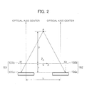
- the stereo camera 10 be disposed so that its optical axis is in parallel to a z-axis of an xz plane in an xyz coordinate system of a three-dimensional space and so that the lenses 101b and 102b are on an x-axis as shown.
- the light from the object A being imaged enters the image pickup element 101a through the lens 101b of the camera 101 so that the x-coordinate x1 is obtained and the light from the object A being imaged enters the image pickup element 102a through the lens 102b of the camera 102 so that the x-coordinate x2 is obtained, then an absolute value of
- a z-coordinate of the object A being imaged that is, a distance D from the stereo camera 10 to the object A being imaged, is calculated as per the following expression using, as parameters, the parallax ⁇ , baseline length of the two cameras (i.e., a distance between optical axes) 'b', and a focal length 'f' between the lens 101b or 102b and the image pickup element 101a or 102a.
- D b ⁇ f / ⁇
- the stereo camera 10 is of a parallel equal-positioned stereo camera with the cameras 101 and 102 arranged side by side, in parallel, and at the same height. It goes without saying, however, that the present invention is not limited to this camera arrangement.
- the camera control unit 12 is a circuit that controls the cameras 101 and 102. More specifically, the camera control unit 12 controls the cameras 101 and 102 to image the object in the same timing. It is because the parallax ⁇ cannot be calculated according to the latest position of the target object to image if the image acquisition timings at cameras 101 and 102 are different and the position of the target object changes between the timings.
- the camera control unit 12 also controls the cameras 101 and 102 so that respective amounts of photographic exposure are equal to each other. This control ensures that if the same target object is associated with the same luminance value in the two source images, matching accuracy improves during a block matching process described later herein.
- the image processing LSI 22 is an image processor that performs the image-based recognition of the object by receiving via the communication bus 24 the two sets of source image data that have been output from the stereo camera 10.
- Fig. 3 shows details of processing executed in the image processing LSI 22.
- the image processing LSI 22 includes correction sections 26a and 26b, a parallax calculation section 28, a parallax image generation section 30, a first reduced-image generation section 32, and an image recognition section 34.
- the correction sections 26a and 26b convert two inputted source image data so that when the two source images are arranged side by side in a lateral direction, the imaged object has the same height.
- the correction sections thereby facilitate the block matching process (described later herein) that the parallax calculation section 28 performs.
- the correction sections 26a and 26b obtain correction data for the conversions by referring to a correction data table, which is stored within the ROM 16, that is created by conducting a calibration in advance. During the calibration, distortions of the lenses 101b and 102b, errors in mounting position/angle of the cameras 101 and 102, and other errors are measured beforehand and the correction data is calculated.
- the parallax calculation section 28 forms a parallax calculator that calculates the parallax by use of the block matching process on the basis of the two sets of source image data that the correction sections 26a and 26b have corrected.
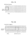
- the block matching process comprises: separating one of the two source images (hereinafter referred to as a reference image), as shown in Fig. 4(a) , with a first block (a thick solid line in the figure) having a predetermined shape so as to include a plurality of pixels, separating the other of the two source images (hereinafter referred to as a comparison image), as shown in Fig.
- the calculation of the correlation value uses a sum of absolute differences (SAD).
- SAD sum of absolute differences
- a distance between a specific pixel (e.g., lower left pixel) in the first block and a specific pixel (e.g., lower left pixel) in the second block at the identified position is calculated as the parallax ⁇ .
- This is regarded as one step, and substantially the same step is executed for all pixels in the reference image.
- the calculated parallax ⁇ is associated with the position of the first block or the second block when the parallax ⁇ is calculated and may be temporarily stored into the RAM 14, for example.
- first block and the second block are each shown as having a substantially square shape with 16 pixels, four in a longitudinal direction and four in a lateral direction, the first block and the second block do not need to be limited to this size and shape and may both be rectangular.
- the number of pixels contained in the first block and the second block may be 'm' in the longitudinal direction and 'n' in the lateral direction (where 'm' and 'n' are both a natural number greater than or equal to 1 and either is greater than or equal to 2).
- the first block and the second block may both be formed into a shape of a parallelogram, containing a plurality of pixels.
- the sizes of the first block and second block used in the block matching process can be changed. For example, if the CPU 18 determines that an ability to recognize the object from the images is likely to decrease for a reason such as weather conditions, the CPU 18 may instruct the parallax calculation section 28 to reduce the sizes of the first block and the second-block. Conversely, if the CPU 18 determines that the weather conditions or the like does not affect the image recognition ability and that priority should be assigned to a processing burden upon the LSI, the CPU 18 may instruct the parallax calculation section 28 to increase the sizes of the first block and the second block.
- the parallax image generation section 30 forms a parallax image generator that generates the parallax image on the basis of the parallax ⁇ that the parallax calculation section 28 calculated.
- the parallax image generation section 30 associates the parallax 5 calculated by the parallax calculation section 28, with the entire set of pixels existing in one of the first block of the reference image and the second block of the comparison image when the calculation was conducted, then repeats the association for all parallaxes ⁇ , and thus generates the parallax image. For this reason, the parallax image is generated on the basis of one of the reference image and the comparison image.
- the association may be conducted by assigning one hue information depending on the parallax ⁇ , to the entire set of pixels in the first block or the second block.
- the parallax image is corresponded to one parallax information per a plurality of the pixels and apparently has lower resolution than the source image in which one luminance information is corresponded to each one of pixels.
- the parallax image generation section 30 may generate the parallax image by sequentially associating the parallax 5 with the reference image or the comparison image every time the parallax ⁇ is calculated, in which case the parallax calculation section 28 will not need to output the calculated parallaxes ⁇ to the RAM 14.
- the first reduced-image generation section 32 forms a first reduced-image generator for generating a first reduced image that is reduced from one of the two source images converted by the correction sections 26a and 26b in accordance with the block used in the block matching by the parallax calculation section 28.
- Which of the two source images is reduced by the first reduced-image generation section 32 depends on whether the generation of the parallax image was based on the reference image or the comparison image. If the parallax image was based on the reference image, the source image that was used as the reference image is reduced, and if the parallax image was based on the comparison image, the source image that was used as the comparison image is reduced.
- One of the two source images is reduced according to a shape of the block used during block matching.
- the source image is reduced so that the number of pixels in a longitudinal direction in the first reduced image is the number of pixels obtained by dividing the number of pixels in the longitudinal direction in the source image by 'm', and so that the number of pixels in a lateral direction in the first reduced image is the number of pixels obtained by dividing the number of pixels in the lateral direction in the source image by 'n'.
- resolution of the parallax image and that of the first reduced image become equal.
- the image recognition section 34 forms an image recognizer that performs the image recognition of the object, based on both the parallax image generated by the parallax calculation section 28, and the first reduced image generated by the first reduced-image generation section 32. To be more specific, the image recognition section 34 performs process of identifying the object by use of pattern matching that uses the luminance information of the first reduced image. The image recognition section 34 performs the image recognition of the object by calculating a three-dimensional position of the identified object from the parallax information of the parallax image. At this time, which region in the parallax image is corresponded to the region of the object identified in the first reduced image, that is, the positions of the corresponding pixels between the parallax image and the first reduced image, are calculated. The object recognition information that the image recognition section 34 has obtained is output to the external IF 20 via the communication bus 24.
- the image processing LSI 22 having the above configuration, since the resolution of the parallax image and that of the first reduced image become equal, it becomes unnecessary for the image recognition section 34 to compute, with respect to all pixels, the corresponding pixel position between the parallax image and the first reduced image. The time consumed in the image recognition process can be correspondingly reduced.
- the sizes of the first block and second block used during block matching by the parallax calculation section 28 are increased in a range not affecting the image recognition ability of the LSI in order to reduce the processing burden upon the LSI when source image data size increases as the stereo camera's resolution becomes high, the time that the image recognition section 34 consumes in the image recognition process is little affected since the resolution of the parallax image and that of the first reduced image are equal.
- the first reduced-image generation section 32 may reduce the source image in the following manner. That is to say, if the first block and the second block are square or rectangular and these blocks contain an 'm' number of pixels in the longitudinal direction and an 'n' number of pixels in the lateral direction, a predetermined value 'k' that is a natural number greater than or equal to 2 may be used to reduce the source image so that the number of pixels in the longitudinal direction in the first reduced image will be the number of pixels obtained by dividing the number of pixels in the longitudinal direction in the source image by (m x k), and so that the number of pixels in the lateral direction in the first reduced image will be the number of pixels obtained by dividing the number of pixels in the lateral direction in the source image by (n x k). If the source image is reduced in this way, the processing burden involved in the position calculation of the corresponding pixel between the parallax image and the first reduced image will also be lighter than if the source image is
- the image processing LSI 22 may include an extracted-image generation section, instead of the first reduced-image generation section 32, to generate an extracted image obtained by partially extracting a source image converted by at least one of the correction sections 26 and 26b.
- the extracted image as compared to the parallax mage, only the luminance information of only part of the imaging range by camera 101 or 102 is obtained.
- the extracted-image generation section may determine the region to watch by focusing on what time variations is shown at each pixel by the luminance information indicated by the source image and generate an extracted image according to shapes of the first block and the second block so as to include the pixels of this region to watch.
- the processing burden of the image recognition section 34 in the image recognition process will then be lighter.
- the source image converted by the correction section 26b has been used for the first reduced-image generation section 32 to generate the first reduced image.
- image generation is not limited to this method and either the source image converted by the correction section 26a, or the two source images converted by both correction sections 26a and 26b, may be used instead.
- Fig. 5 is a diagram that shows details of processing executed by image recognition LSI 36 in the second embodiment of the present invention.
- the image recognition LSI 36 in the second embodiment differs from the image recognition LSI 22 in the first embodiment in that processes by second reduced-image generators 38a and 38b are added between correction sections 26a and 26b and a parallax calculation section 28.
- the second reduced-image generators 38a and 38b each form a second reduced-image generator for respectively reducing a source image converted by the correction section 26a or 26b to generate two second reduced image.
- the second reduced images generated by the second reduced-image generators 38a and 38b are used for the parallax calculation section 28 to calculate a parallax.
- the second reduced-image generators 38a and 38b restore a color based on a pattern of the color filter and reduce the two source images converted by the correction sections 26a and 26b according to the pattern of the color filter.
- the second reduced-image generation section 38a, 38b generates a second reduced image by using a predetermined number 'h' greater than or equal to 1 so that the number of pixels in a longitudinal direction in the second reduced image is the number of pixels obtained by dividing the number of pixels in longitudinal directions of the two source images by (i x h), and so that the number of pixels in a lateral direction in the second reduced image is the number of pixels obtained by dividing the number of pixels in lateral directions of the two source images by (j x h).
- the second reduced-image generation section 38a, 38b generates a second reduced image so that the number of pixels in a longitudinal direction in the second reduced image is the number of pixels obtained by dividing the number of pixels in longitudinal directions of the two source images by (2 x h), and so that the number of pixels in a lateral direction in the second reduced image is the number of pixels obtained by dividing the number of pixels in lateral directions of the two source images by (2 x h).
- optical low-pass filters inserted between the lens 101b and the image pickup element 101a and between the lens 102b and the image pickup element 102a are unnecessary, which contributes at least to reducing manufacturing costs of the image recognition system.
Landscapes
- Engineering & Computer Science (AREA)
- Multimedia (AREA)
- Theoretical Computer Science (AREA)
- Physics & Mathematics (AREA)
- General Physics & Mathematics (AREA)
- Signal Processing (AREA)
- Computer Vision & Pattern Recognition (AREA)
- Image Analysis (AREA)
- Image Processing (AREA)
- Measurement Of Optical Distance (AREA)
- Testing, Inspecting, Measuring Of Stereoscopic Televisions And Televisions (AREA)
- Studio Devices (AREA)
- Length Measuring Devices By Optical Means (AREA)
Abstract
Description
- The present invention relates to image processing devices that perform image recognition of an object.
- An image-processing device for performing image recognition of an object is known (See
Patent Document 1, for example). The image-processing device performs image recognition process comprising: calculating the amount of shift in position of an object (namely parallax (disparity) ), generating a parallax image, and recognizing a three-dimensional position of the object by using the parallax image and the source images. - Patent Document 1:
JP-2009-146217-A - With consideration for reduction of processing load upon the image processing device, the generation of the parallax image may be based on the parallax that has been calculated by block matching. In this case, the parallax is calculated for each block that has been used during block matching, that is, one by one for each of a plurality of pixels. Thus, the parallax image in which one parallax information is corresponded to each of a plurality of pixels apparently has lower resolution than the source image in which one luminance information is corresponded to each one of pixels.
- However, where the resolution of the parallax image differs from that of each source image, the position of the corresponding pixel between the parallax image and the source image will need to be calculated for each pixel during the image recognition process performed using the two images, and the image recognition process is likely to consume a correspondingly large amount of time. The processing time can be reduced by performing the image recognition process in parallel, but the circuit structure required for the process would be larger-sized or more complex.
- Accordingly, the present invention that has been made with the above problems in mind is intended to provide an image processing device adapted to reduce a processing time required for an image recognition process relating to an object.
- To this end, an image processing device according to an aspect of the present invention calculates, by use of block matching, a parallax based on two source images of an object acquired with two cameras, and generates a parallax image on the basis of the calculated parallax. In addition, the device generates a reduced image by reducing at least one of the two source images so that the source image matches with the parallax image, and performs image recognition of the object on the basis of the parallax image and the reduced image.
- The image processing device according to an aspect of the present invention reduces a processing time required for the image recognition process relating to the object.
-
-
Fig. 1 is an explanatory diagram schematically showing an image recognition system configuration in a first embodiment of the present invention. -
Fig. 2 is an explanatory diagram showing a stereo camera and a triangulation technique using the camera. -
Fig. 3 is a block diagram that shows details of processing executed by image recognition LSI in the first embodiment of the present invention. -
Fig. 4 shows a block matching process, with section (a) ofFig. 4 representing a method of setting a first block in a reference image, and section (b) ofFig. 4 representing a method of searching by a second block in a comparison image. -
Fig. 5 is a block diagram that shows details of processing executed by image recognition LSI in another embodiment of the present invention. - Hereunder, a first exemplary embodiment of the present invention will be described with reference to the accompanying drawings.
- An image processing device according to the present embodiment calculates, by use of block matching, a shift in position of an object, that is, a parallax, on a pair of images that a stereo camera obtains by imaging the object in the same timing but from different positions, and then calculates a three-dimensional position of the object by use of a known conversion equation. That is to say, the present device performs image-based recognition of objects. The device can be applied to various systems that require object recognition, such as a surveillance system that monitors for intrusions of suspicious individuals, and a vehicle-mounted system that predicts a risk of collisions against obstacles and supports safe driving.
-
Fig. 1 shows an example of an image recognition system including the image processing device. - The image recognition system includes the following elements: a
stereo camera 10 constituted by twocameras camera control unit 12 that controls thestereo camera 10; a random-access memory (RAM) 14 that is a temporary storage region; read-only memory (ROM) 16 for storing programs and various initial values; a central processing unit (CPU) 18 that controls the entire image recognition system; an external interface (IF) 20 from which recognition information on the object recognized by the image recognition system is output to the outside of the image recognition system; and image recognition large-scale integration (LSI) 22. The system elements exchange data via acommunication bus 24. - As shown in
Fig. 2 , thestereo camera 10 includesimage pickup elements image pickup elements lenses stereo camera 10 converts the light into an electrical signal corresponding to intensity of the light. The thus-obtained electrical signal is output to theRAM 14 via thecommunication bus 24 or directly output to theimage processing LSI 22, as source image data that represents luminance information about the object being imaged. Sizes of the source images depend on the number of pixels in theimage pickup element - Let the
stereo camera 10 be disposed so that its optical axis is in parallel to a z-axis of an xz plane in an xyz coordinate system of a three-dimensional space and so that thelenses image pickup element 101a through thelens 101b of thecamera 101 so that the x-coordinate x1 is obtained and the light from the object A being imaged enters theimage pickup element 102a through thelens 102b of thecamera 102 so that the x-coordinate x2 is obtained, then an absolute value of |x1-x2| of a difference between the x-coordinate x1 and the x-coordinate x2 is obtained as a parallax δ. A z-coordinate of the object A being imaged, that is, a distance D from thestereo camera 10 to the object A being imaged, is calculated as per the following expression using, as parameters, the parallax δ, baseline length of the two cameras (i.e., a distance between optical axes) 'b', and a focal length 'f' between thelens image pickup element

- The following description of the present embodiment assumes that the
stereo camera 10 is of a parallel equal-positioned stereo camera with thecameras - The
camera control unit 12 is a circuit that controls thecameras camera control unit 12 controls thecameras cameras camera control unit 12 also controls thecameras - The
image processing LSI 22 is an image processor that performs the image-based recognition of the object by receiving via thecommunication bus 24 the two sets of source image data that have been output from thestereo camera 10. -
Fig. 3 shows details of processing executed in theimage processing LSI 22. - The
image processing LSI 22 includescorrection sections parallax calculation section 28, a parallaximage generation section 30, a first reduced-image generation section 32, and animage recognition section 34. - The
correction sections parallax calculation section 28 performs. Thecorrection sections ROM 16, that is created by conducting a calibration in advance. During the calibration, distortions of thelenses cameras - The
parallax calculation section 28 forms a parallax calculator that calculates the parallax by use of the block matching process on the basis of the two sets of source image data that thecorrection sections - The block matching process comprises: separating one of the two source images (hereinafter referred to as a reference image), as shown in
Fig. 4(a) , with a first block (a thick solid line in the figure) having a predetermined shape so as to include a plurality of pixels, separating the other of the two source images (hereinafter referred to as a comparison image), as shown inFig. 4(b) , with a second block (a thick solid line in the figure) of the same size, shape, and position as those of the first block, shifting the second block in increments of one pixel in a lateral direction, calculating a correlation value between two luminance patterns in the first block and the second block, and searching the position where the correlation value becomes the lowest, that is, the correlation is the highest. In the present embodiment, the calculation of the correlation value uses a sum of absolute differences (SAD). However, the use of SAD is not the only calculating method usable and any other known method can be used. If the position of the highest (strongest) correlation is identified as a result of the search, a distance between a specific pixel (e.g., lower left pixel) in the first block and a specific pixel (e.g., lower left pixel) in the second block at the identified position is calculated as the parallax δ. This is regarded as one step, and substantially the same step is executed for all pixels in the reference image. The calculated parallax δ is associated with the position of the first block or the second block when the parallax δ is calculated and may be temporarily stored into theRAM 14, for example. - While in sections (a) and (b) of
Fig. 4 the first block and the second block are each shown as having a substantially square shape with 16 pixels, four in a longitudinal direction and four in a lateral direction, the first block and the second block do not need to be limited to this size and shape and may both be rectangular. In other words, the number of pixels contained in the first block and the second block may be 'm' in the longitudinal direction and 'n' in the lateral direction (where 'm' and 'n' are both a natural number greater than or equal to 1 and either is greater than or equal to 2). In addition, if the source images are parallelograms, the first block and the second block may both be formed into a shape of a parallelogram, containing a plurality of pixels. - The sizes of the first block and second block used in the block matching process can be changed. For example, if the
CPU 18 determines that an ability to recognize the object from the images is likely to decrease for a reason such as weather conditions, theCPU 18 may instruct theparallax calculation section 28 to reduce the sizes of the first block and the second-block. Conversely, if theCPU 18 determines that the weather conditions or the like does not affect the image recognition ability and that priority should be assigned to a processing burden upon the LSI, theCPU 18 may instruct theparallax calculation section 28 to increase the sizes of the first block and the second block. - The parallax
image generation section 30 forms a parallax image generator that generates the parallax image on the basis of the parallax δ that theparallax calculation section 28 calculated. - The parallax
image generation section 30 associates the parallax 5 calculated by theparallax calculation section 28, with the entire set of pixels existing in one of the first block of the reference image and the second block of the comparison image when the calculation was conducted, then repeats the association for all parallaxes δ, and thus generates the parallax image. For this reason, the parallax image is generated on the basis of one of the reference image and the comparison image. The association may be conducted by assigning one hue information depending on the parallax δ, to the entire set of pixels in the first block or the second block. The parallax image is corresponded to one parallax information per a plurality of the pixels and apparently has lower resolution than the source image in which one luminance information is corresponded to each one of pixels. - Instead of starting the generation of the parallax image after the calculation of all parallaxes δ by the
parallax calculation section 28, the parallaximage generation section 30 may generate the parallax image by sequentially associating the parallax 5 with the reference image or the comparison image every time the parallax δ is calculated, in which case theparallax calculation section 28 will not need to output the calculated parallaxes δ to theRAM 14. - The first reduced-
image generation section 32 forms a first reduced-image generator for generating a first reduced image that is reduced from one of the two source images converted by thecorrection sections parallax calculation section 28. - Which of the two source images is reduced by the first reduced-
image generation section 32 depends on whether the generation of the parallax image was based on the reference image or the comparison image. If the parallax image was based on the reference image, the source image that was used as the reference image is reduced, and if the parallax image was based on the comparison image, the source image that was used as the comparison image is reduced. - A method of the reduction is described in detail below. One of the two source images is reduced according to a shape of the block used during block matching. For example, if the first block and the second block are square or rectangular in shape and this shape contains an (m by n) number of pixels formed by an 'm' number of pixels in the longitudinal direction and an 'n' number of pixels in the lateral direction, the source image is reduced so that the number of pixels in a longitudinal direction in the first reduced image is the number of pixels obtained by dividing the number of pixels in the longitudinal direction in the source image by 'm', and so that the number of pixels in a lateral direction in the first reduced image is the number of pixels obtained by dividing the number of pixels in the lateral direction in the source image by 'n'. Thus, resolution of the parallax image and that of the first reduced image become equal.
- The
image recognition section 34 forms an image recognizer that performs the image recognition of the object, based on both the parallax image generated by theparallax calculation section 28, and the first reduced image generated by the first reduced-image generation section 32. To be more specific, theimage recognition section 34 performs process of identifying the object by use of pattern matching that uses the luminance information of the first reduced image. Theimage recognition section 34 performs the image recognition of the object by calculating a three-dimensional position of the identified object from the parallax information of the parallax image. At this time, which region in the parallax image is corresponded to the region of the object identified in the first reduced image, that is, the positions of the corresponding pixels between the parallax image and the first reduced image, are calculated. The object recognition information that theimage recognition section 34 has obtained is output to the external IF 20 via thecommunication bus 24. - In the
image processing LSI 22 having the above configuration, since the resolution of the parallax image and that of the first reduced image become equal, it becomes unnecessary for theimage recognition section 34 to compute, with respect to all pixels, the corresponding pixel position between the parallax image and the first reduced image. The time consumed in the image recognition process can be correspondingly reduced. - In addition, if the sizes of the first block and second block used during block matching by the
parallax calculation section 28 are increased in a range not affecting the image recognition ability of the LSI in order to reduce the processing burden upon the LSI when source image data size increases as the stereo camera's resolution becomes high, the time that theimage recognition section 34 consumes in the image recognition process is little affected since the resolution of the parallax image and that of the first reduced image are equal. - When the
RAM 14 has a capacity large enough to enable high-resolution image saving, the first reduced-image generation section 32 may reduce the source image in the following manner. That is to say, if the first block and the second block are square or rectangular and these blocks contain an 'm' number of pixels in the longitudinal direction and an 'n' number of pixels in the lateral direction, a predetermined value 'k' that is a natural number greater than or equal to 2 may be used to reduce the source image so that the number of pixels in the longitudinal direction in the first reduced image will be the number of pixels obtained by dividing the number of pixels in the longitudinal direction in the source image by (m x k), and so that the number of pixels in the lateral direction in the first reduced image will be the number of pixels obtained by dividing the number of pixels in the lateral direction in the source image by (n x k). If the source image is reduced in this way, the processing burden involved in the position calculation of the corresponding pixel between the parallax image and the first reduced image will also be lighter than if the source image is not reduced. - In the embodiment described above, the
image processing LSI 22 may include an extracted-image generation section, instead of the first reduced-image generation section 32, to generate an extracted image obtained by partially extracting a source image converted by at least one of thecorrection sections 26 and 26b. In the extracted image, as compared to the parallax mage, only the luminance information of only part of the imaging range bycamera image recognition section 34 in the image recognition process will then be lighter. - In addition, in the embodiment described above, of the
correction sections correction section 26b has been used for the first reduced-image generation section 32 to generate the first reduced image. However, image generation is not limited to this method and either the source image converted by thecorrection section 26a, or the two source images converted by bothcorrection sections - Next, a second exemplary embodiment of the present invention will be described. The same elements as in the first embodiment will be assigned the same reference numbers, and description of these elements will be omitted or simplified.
-
Fig. 5 is a diagram that shows details of processing executed byimage recognition LSI 36 in the second embodiment of the present invention. - The
image recognition LSI 36 in the second embodiment differs from theimage recognition LSI 22 in the first embodiment in that processes by second reduced-image generators correction sections parallax calculation section 28. - The second reduced-
image generators correction section correction sections image generators parallax calculation section 28 to calculate a parallax. - In addition, if the
image pickup elements cameras image generators correction sections - For example, if the color filter has a pattern cyclically appearing in units of an (i x j) number of pixels formed by an 'i' number of pixels in a longitudinal direction and a 'j' number of pixels in a lateral direction, the second reduced-
image generation section image generation section - With the above-described
image processing LSI 36 of the second embodiment, if resolution of astereo camera 10 becomes high to suppress a false color that often becomes a problem in color reproduction process, a processing burden upon theparallax calculation section 28 is reduced since the source images that have been output from thestereo camera 10 are reduced in size by the second reduced-image generators - Additionally, in order to suppress occurrence of a false color, optical low-pass filters inserted between the
lens 101b and theimage pickup element 101a and between thelens 102b and theimage pickup element 102a are unnecessary, which contributes at least to reducing manufacturing costs of the image recognition system. -
- 10: Stereo camera
- 101: Camera
- 102: Camera
- 101a: Image pickup element
- 102a: Image pickup element
- 22: Image processing LSI
- 24: Communication bus
- 28: Parallax calculation section
- 30: Parallax image generation section
- 32: First reduced-image generation section
- 34: Image recognition section
- 36a: Second reduced-image generation section
- 36b: Second reduced-image generation section
Claims (8)
- An image processing device comprising:a parallax calculator for calculating a parallax by using a block matching on the basis of two source images of an object that are acquired with two cameras;a parallax image generator for generating a parallax image on the basis of the parallax calculated by the parallax calculator;a first reduced-image generator for generating a first reduced image by reducing at least one of the two source images so that the source image matches with the parallax image; andan image recognizer for performing image recognition of the object, based upon the parallax image and the first reduced image.
- The image processing device according to claim 1, wherein the first reduced-image generator reduces at least one of the two source images according to a shape of a block used in the block matching.
- The image processing device according to claim 2, wherein the shape of the block is square or rectangular.
- The image processing device according to claim 3, wherein, where the number of pixels contained in the block is 'm' in a longitudinal direction and 'n' in a lateral direction, the first reduced-image generator generates the first reduced image by using a predetermined number 'k' greater than or equal to 1 in terms of natural number so that the number of pixels in a longitudinal direction of the first reduced image is the number of pixels obtained by dividing the number of pixels in longitudinal directions of the two source images by (m x k), and so that the number of pixels in a lateral direction of the first reduced image is the number of pixels obtained by dividing the number of pixels in lateral directions of the two source images by (n x k).
- The image processing device according to claim 4, wherein the predetermined number 'k' is 1.
- The image processing device according to any one of claims 1 to 5, further comprising a second reduced-image generator for respectively generating two second reduced images by reducing the two source images, the two second reduced images being used, instead of the two source images, for the parallax calculator to calculate a parallax.
- The image processing device according to claim 6, wherein, where image pickup elements of the two cameras comprise a color filter, the second reduced-image generator restores a color on the basis of a pattern of the color filter, the second reduced-image generator further reducing the two source images according to the pattern of the color filter.
- The image processing device according to claim 7, wherein, where the pattern of the color filter cyclically appears with every 'i' pixels in a longitudinal direction and every 'j' pixels in a lateral direction, the second reduced-image generator generates the second reduced image by using a predetermined number 'h' greater than or equal to 1 so that the number of pixels in a longitudinal direction in the second reduced image is the number of pixels obtained by dividing the number of pixels in longitudinal directions of the two source images by (i x h), and so that the number of pixels in a lateral direction in the second reduced image is the number of pixels obtained by dividing the number of pixels in lateral directions of the two source images by (j x h).
Applications Claiming Priority (2)
| Application Number | Priority Date | Filing Date | Title |
|---|---|---|---|
| JP2012237591A JP6071422B2 (en) | 2012-10-29 | 2012-10-29 | Image processing device |
| PCT/JP2013/077195 WO2014069169A1 (en) | 2012-10-29 | 2013-10-07 | Image processing device |
Publications (4)
| Publication Number | Publication Date |
|---|---|
| EP2914001A1 true EP2914001A1 (en) | 2015-09-02 |
| EP2914001A9 EP2914001A9 (en) | 2016-03-02 |
| EP2914001A4 EP2914001A4 (en) | 2016-07-06 |
| EP2914001B1 EP2914001B1 (en) | 2019-08-14 |
Family
ID=50627085
Family Applications (1)
| Application Number | Title | Priority Date | Filing Date |
|---|---|---|---|
| EP13852310.5A Active EP2914001B1 (en) | 2012-10-29 | 2013-10-07 | Image processing device |
Country Status (4)
| Country | Link |
|---|---|
| US (1) | US9652853B2 (en) |
| EP (1) | EP2914001B1 (en) |
| JP (1) | JP6071422B2 (en) |
| WO (1) | WO2014069169A1 (en) |
Families Citing this family (11)
| Publication number | Priority date | Publication date | Assignee | Title |
|---|---|---|---|---|
| KR101882931B1 (en) | 2014-07-10 | 2018-07-30 | 삼성전자주식회사 | Multi view image display apparatus and disparity estimation method of thereof |
| DE102015112289A1 (en) * | 2015-07-28 | 2017-02-02 | Valeo Schalter Und Sensoren Gmbh | Method for identifying an object in a surrounding area of a motor vehicle, driver assistance system and motor vehicle |
| JP6780983B2 (en) * | 2016-08-18 | 2020-11-04 | マクセル株式会社 | Image processing system |
| JP6853928B2 (en) * | 2016-11-10 | 2021-04-07 | 株式会社金子製作所 | 3D moving image display processing device and program |
| JP2018207259A (en) * | 2017-06-01 | 2018-12-27 | マクセル株式会社 | Stereo imaging device |
| KR20190013224A (en) * | 2017-08-01 | 2019-02-11 | 엘지전자 주식회사 | Mobile terminal |
| JP7227969B2 (en) * | 2018-05-30 | 2023-02-22 | パナソニック インテレクチュアル プロパティ コーポレーション オブ アメリカ | Three-dimensional reconstruction method and three-dimensional reconstruction apparatus |
| JP2022053086A (en) * | 2020-09-24 | 2022-04-05 | トヨタ自動車株式会社 | Self-position estimation system and self-position estimation method |
| TWI825892B (en) * | 2022-08-02 | 2023-12-11 | 宏碁股份有限公司 | 3d format image detection method and electronic apparatus using the same method |
| TWI826033B (en) * | 2022-10-07 | 2023-12-11 | 宏碁股份有限公司 | Image display method and 3d display system |
| JP2024058817A (en) * | 2022-10-17 | 2024-04-30 | キヤノン株式会社 | Imaging device, imaging method, program, and recording medium |
Family Cites Families (13)
| Publication number | Priority date | Publication date | Assignee | Title |
|---|---|---|---|---|
| EP0641132B1 (en) * | 1993-08-26 | 1999-04-14 | Matsushita Electric Industrial Co., Ltd. | Stereoscopic image pickup apparatus |
| KR100414629B1 (en) * | 1995-03-29 | 2004-05-03 | 산요덴키가부시키가이샤 | 3D display image generation method, image processing method using depth information, depth information generation method |
| JP2003150936A (en) | 2001-11-08 | 2003-05-23 | Fuji Heavy Ind Ltd | Image processing apparatus and image processing method |
| JP4275378B2 (en) * | 2002-09-27 | 2009-06-10 | 富士重工業株式会社 | Stereo image processing apparatus and stereo image processing method |
| JP4831514B2 (en) * | 2007-11-13 | 2011-12-07 | 独立行政法人情報通信研究機構 | Setting parameter optimization device and program thereof |
| JP5172314B2 (en) | 2007-12-14 | 2013-03-27 | 日立オートモティブシステムズ株式会社 | Stereo camera device |
| JP4382156B2 (en) * | 2008-02-12 | 2009-12-09 | パナソニック株式会社 | Compound eye imaging device, distance measuring device, parallax calculation method, and distance measuring method |
| JP4807474B2 (en) * | 2009-06-19 | 2011-11-02 | パナソニック株式会社 | Consumable electrode arc welding method and consumable electrode arc welding apparatus |
| JP5468426B2 (en) * | 2010-03-12 | 2014-04-09 | 日立オートモティブシステムズ株式会社 | Stereo camera device |
| JP2012150614A (en) * | 2011-01-18 | 2012-08-09 | Nagoya Univ | Free viewpoint image generation device |
| US9087375B2 (en) * | 2011-03-28 | 2015-07-21 | Sony Corporation | Image processing device, image processing method, and program |
| JP5622648B2 (en) * | 2011-04-14 | 2014-11-12 | 日立オートモティブシステムズ株式会社 | Image processing device |
| JP5762211B2 (en) * | 2011-08-11 | 2015-08-12 | キヤノン株式会社 | Image processing apparatus, image processing method, and program |
-
2012
- 2012-10-29 JP JP2012237591A patent/JP6071422B2/en active Active
-
2013
- 2013-10-07 US US14/439,076 patent/US9652853B2/en active Active
- 2013-10-07 WO PCT/JP2013/077195 patent/WO2014069169A1/en not_active Ceased
- 2013-10-07 EP EP13852310.5A patent/EP2914001B1/en active Active
Also Published As
| Publication number | Publication date |
|---|---|
| EP2914001B1 (en) | 2019-08-14 |
| WO2014069169A1 (en) | 2014-05-08 |
| US9652853B2 (en) | 2017-05-16 |
| JP2014090233A (en) | 2014-05-15 |
| CN104769942A (en) | 2015-07-08 |
| US20150310621A1 (en) | 2015-10-29 |
| JP6071422B2 (en) | 2017-02-01 |
| EP2914001A4 (en) | 2016-07-06 |
| EP2914001A9 (en) | 2016-03-02 |
Similar Documents
| Publication | Publication Date | Title |
|---|---|---|
| EP2914001B1 (en) | Image processing device | |
| JP6417886B2 (en) | Parallax value deriving device, moving body, robot, parallax value production method, and program | |
| JP7038345B2 (en) | Camera parameter set calculation method, camera parameter set calculation program and camera parameter set calculation device | |
| US10218960B2 (en) | Stereoscopic imaging apparatus | |
| JP6970577B2 (en) | Peripheral monitoring device and peripheral monitoring method | |
| US8817121B2 (en) | Image apparatus and imaging method | |
| EP4050553B1 (en) | Method and device for restoring image obtained from array camera | |
| JP6020471B2 (en) | Image processing method, image processing apparatus, and image processing program | |
| KR20210087809A (en) | Electronic device comprising image sensor and method of operation thereof | |
| WO2023067867A1 (en) | Vehicle-mounted control device, and three-dimensional information acquisition method | |
| JP4042750B2 (en) | Image processing apparatus, computer program, and image processing method | |
| US20190318495A1 (en) | Image processing system | |
| JP2016070774A (en) | Parallax value derivation device, moving body, robot, parallax value production method and program | |
| CN111260538B (en) | Positioning and vehicle-mounted terminal based on long baseline binocular fisheye camera | |
| US20230306566A1 (en) | Image processing apparatus, image processing method, and storage medium | |
| EP2727077A1 (en) | A system and method for resolution enhancement | |
| KR101907852B1 (en) | Method and Apparatus for Processing Stereo Images | |
| CN104769942B (en) | Image processing apparatus | |
| JP2023057950A (en) | Control device, imaging device, control method, program and storage medium | |
| US10078880B2 (en) | Image processing device and image processing system | |
| JP2018148513A (en) | Image processing system, image processing method, and program | |
| JP2016095229A (en) | Parallax value deriving device, moving body, robot, parallax value production method, and program | |
| JP7652739B2 (en) | Image processing device and image processing method | |
| US20190253694A1 (en) | Camera device | |
| US20190058869A1 (en) | Stereoscopic image-capturing apparatus |
Legal Events
| Date | Code | Title | Description |
|---|---|---|---|
| PUAI | Public reference made under article 153(3) epc to a published international application that has entered the european phase |
Free format text: ORIGINAL CODE: 0009012 |
|
| 17P | Request for examination filed |
Effective date: 20150529 |
|
| AK | Designated contracting states |
Kind code of ref document: A1 Designated state(s): AL AT BE BG CH CY CZ DE DK EE ES FI FR GB GR HR HU IE IS IT LI LT LU LV MC MK MT NL NO PL PT RO RS SE SI SK SM TR |
|
| AX | Request for extension of the european patent |
Extension state: BA ME |
|
| DAX | Request for extension of the european patent (deleted) | ||
| RA4 | Supplementary search report drawn up and despatched (corrected) |
Effective date: 20160608 |
|
| RIC1 | Information provided on ipc code assigned before grant |
Ipc: H04N 13/02 20060101ALI20160602BHEP Ipc: H04N 5/225 20060101ALI20160602BHEP Ipc: H04N 13/00 20060101AFI20160602BHEP Ipc: H04N 13/04 20060101ALI20160602BHEP Ipc: G06T 7/00 20060101ALI20160602BHEP Ipc: G06T 7/20 20060101ALI20160602BHEP Ipc: G06K 9/00 20060101ALI20160602BHEP |
|
| STAA | Information on the status of an ep patent application or granted ep patent |
Free format text: STATUS: EXAMINATION IS IN PROGRESS |
|
| 17Q | First examination report despatched |
Effective date: 20180718 |
|
| REG | Reference to a national code |
Ref country code: DE Ref legal event code: R079 Ref document number: 602013059288 Country of ref document: DE Free format text: PREVIOUS MAIN CLASS: H04N0013020000 Ipc: H04N0013271000 |
|
| GRAP | Despatch of communication of intention to grant a patent |
Free format text: ORIGINAL CODE: EPIDOSNIGR1 |
|
| STAA | Information on the status of an ep patent application or granted ep patent |
Free format text: STATUS: GRANT OF PATENT IS INTENDED |
|
| RIC1 | Information provided on ipc code assigned before grant |
Ipc: G06T 7/593 20170101ALI20190219BHEP Ipc: G06K 9/00 20060101ALI20190219BHEP Ipc: H04N 13/271 20180101AFI20190219BHEP Ipc: H04N 13/00 20180101ALI20190219BHEP Ipc: H04N 13/239 20180101ALI20190219BHEP Ipc: H04N 5/225 20060101ALI20190219BHEP |
|
| INTG | Intention to grant announced |
Effective date: 20190307 |
|
| GRAS | Grant fee paid |
Free format text: ORIGINAL CODE: EPIDOSNIGR3 |
|
| GRAA | (expected) grant |
Free format text: ORIGINAL CODE: 0009210 |
|
| STAA | Information on the status of an ep patent application or granted ep patent |
Free format text: STATUS: THE PATENT HAS BEEN GRANTED |
|
| AK | Designated contracting states |
Kind code of ref document: B1 Designated state(s): AL AT BE BG CH CY CZ DE DK EE ES FI FR GB GR HR HU IE IS IT LI LT LU LV MC MK MT NL NO PL PT RO RS SE SI SK SM TR |
|
| REG | Reference to a national code |
Ref country code: GB Ref legal event code: FG4D |
|
| REG | Reference to a national code |
Ref country code: CH Ref legal event code: EP Ref country code: AT Ref legal event code: REF Ref document number: 1168436 Country of ref document: AT Kind code of ref document: T Effective date: 20190815 |
|
| REG | Reference to a national code |
Ref country code: DE Ref legal event code: R096 Ref document number: 602013059288 Country of ref document: DE |
|
| REG | Reference to a national code |
Ref country code: IE Ref legal event code: FG4D |
|
| REG | Reference to a national code |
Ref country code: NL Ref legal event code: MP Effective date: 20190814 |
|
| REG | Reference to a national code |
Ref country code: LT Ref legal event code: MG4D |
|
| PG25 | Lapsed in a contracting state [announced via postgrant information from national office to epo] |
Ref country code: LT Free format text: LAPSE BECAUSE OF FAILURE TO SUBMIT A TRANSLATION OF THE DESCRIPTION OR TO PAY THE FEE WITHIN THE PRESCRIBED TIME-LIMIT Effective date: 20190814 Ref country code: HR Free format text: LAPSE BECAUSE OF FAILURE TO SUBMIT A TRANSLATION OF THE DESCRIPTION OR TO PAY THE FEE WITHIN THE PRESCRIBED TIME-LIMIT Effective date: 20190814 Ref country code: NO Free format text: LAPSE BECAUSE OF FAILURE TO SUBMIT A TRANSLATION OF THE DESCRIPTION OR TO PAY THE FEE WITHIN THE PRESCRIBED TIME-LIMIT Effective date: 20191114 Ref country code: BG Free format text: LAPSE BECAUSE OF FAILURE TO SUBMIT A TRANSLATION OF THE DESCRIPTION OR TO PAY THE FEE WITHIN THE PRESCRIBED TIME-LIMIT Effective date: 20191114 Ref country code: NL Free format text: LAPSE BECAUSE OF FAILURE TO SUBMIT A TRANSLATION OF THE DESCRIPTION OR TO PAY THE FEE WITHIN THE PRESCRIBED TIME-LIMIT Effective date: 20190814 Ref country code: PT Free format text: LAPSE BECAUSE OF FAILURE TO SUBMIT A TRANSLATION OF THE DESCRIPTION OR TO PAY THE FEE WITHIN THE PRESCRIBED TIME-LIMIT Effective date: 20191216 Ref country code: FI Free format text: LAPSE BECAUSE OF FAILURE TO SUBMIT A TRANSLATION OF THE DESCRIPTION OR TO PAY THE FEE WITHIN THE PRESCRIBED TIME-LIMIT Effective date: 20190814 Ref country code: SE Free format text: LAPSE BECAUSE OF FAILURE TO SUBMIT A TRANSLATION OF THE DESCRIPTION OR TO PAY THE FEE WITHIN THE PRESCRIBED TIME-LIMIT Effective date: 20190814 |
|
| REG | Reference to a national code |
Ref country code: AT Ref legal event code: MK05 Ref document number: 1168436 Country of ref document: AT Kind code of ref document: T Effective date: 20190814 |
|
| PG25 | Lapsed in a contracting state [announced via postgrant information from national office to epo] |
Ref country code: RS Free format text: LAPSE BECAUSE OF FAILURE TO SUBMIT A TRANSLATION OF THE DESCRIPTION OR TO PAY THE FEE WITHIN THE PRESCRIBED TIME-LIMIT Effective date: 20190814 Ref country code: LV Free format text: LAPSE BECAUSE OF FAILURE TO SUBMIT A TRANSLATION OF THE DESCRIPTION OR TO PAY THE FEE WITHIN THE PRESCRIBED TIME-LIMIT Effective date: 20190814 Ref country code: GR Free format text: LAPSE BECAUSE OF FAILURE TO SUBMIT A TRANSLATION OF THE DESCRIPTION OR TO PAY THE FEE WITHIN THE PRESCRIBED TIME-LIMIT Effective date: 20191115 Ref country code: IS Free format text: LAPSE BECAUSE OF FAILURE TO SUBMIT A TRANSLATION OF THE DESCRIPTION OR TO PAY THE FEE WITHIN THE PRESCRIBED TIME-LIMIT Effective date: 20191214 Ref country code: AL Free format text: LAPSE BECAUSE OF FAILURE TO SUBMIT A TRANSLATION OF THE DESCRIPTION OR TO PAY THE FEE WITHIN THE PRESCRIBED TIME-LIMIT Effective date: 20190814 Ref country code: ES Free format text: LAPSE BECAUSE OF FAILURE TO SUBMIT A TRANSLATION OF THE DESCRIPTION OR TO PAY THE FEE WITHIN THE PRESCRIBED TIME-LIMIT Effective date: 20190814 |
|
| PG25 | Lapsed in a contracting state [announced via postgrant information from national office to epo] |
Ref country code: TR Free format text: LAPSE BECAUSE OF FAILURE TO SUBMIT A TRANSLATION OF THE DESCRIPTION OR TO PAY THE FEE WITHIN THE PRESCRIBED TIME-LIMIT Effective date: 20190814 |
|
| PG25 | Lapsed in a contracting state [announced via postgrant information from national office to epo] |
Ref country code: DK Free format text: LAPSE BECAUSE OF FAILURE TO SUBMIT A TRANSLATION OF THE DESCRIPTION OR TO PAY THE FEE WITHIN THE PRESCRIBED TIME-LIMIT Effective date: 20190814 Ref country code: AT Free format text: LAPSE BECAUSE OF FAILURE TO SUBMIT A TRANSLATION OF THE DESCRIPTION OR TO PAY THE FEE WITHIN THE PRESCRIBED TIME-LIMIT Effective date: 20190814 Ref country code: EE Free format text: LAPSE BECAUSE OF FAILURE TO SUBMIT A TRANSLATION OF THE DESCRIPTION OR TO PAY THE FEE WITHIN THE PRESCRIBED TIME-LIMIT Effective date: 20190814 Ref country code: IT Free format text: LAPSE BECAUSE OF FAILURE TO SUBMIT A TRANSLATION OF THE DESCRIPTION OR TO PAY THE FEE WITHIN THE PRESCRIBED TIME-LIMIT Effective date: 20190814 Ref country code: RO Free format text: LAPSE BECAUSE OF FAILURE TO SUBMIT A TRANSLATION OF THE DESCRIPTION OR TO PAY THE FEE WITHIN THE PRESCRIBED TIME-LIMIT Effective date: 20190814 Ref country code: PL Free format text: LAPSE BECAUSE OF FAILURE TO SUBMIT A TRANSLATION OF THE DESCRIPTION OR TO PAY THE FEE WITHIN THE PRESCRIBED TIME-LIMIT Effective date: 20190814 |
|
| PG25 | Lapsed in a contracting state [announced via postgrant information from national office to epo] |
Ref country code: SK Free format text: LAPSE BECAUSE OF FAILURE TO SUBMIT A TRANSLATION OF THE DESCRIPTION OR TO PAY THE FEE WITHIN THE PRESCRIBED TIME-LIMIT Effective date: 20190814 Ref country code: CZ Free format text: LAPSE BECAUSE OF FAILURE TO SUBMIT A TRANSLATION OF THE DESCRIPTION OR TO PAY THE FEE WITHIN THE PRESCRIBED TIME-LIMIT Effective date: 20190814 Ref country code: MC Free format text: LAPSE BECAUSE OF FAILURE TO SUBMIT A TRANSLATION OF THE DESCRIPTION OR TO PAY THE FEE WITHIN THE PRESCRIBED TIME-LIMIT Effective date: 20190814 Ref country code: IS Free format text: LAPSE BECAUSE OF FAILURE TO SUBMIT A TRANSLATION OF THE DESCRIPTION OR TO PAY THE FEE WITHIN THE PRESCRIBED TIME-LIMIT Effective date: 20200224 Ref country code: SM Free format text: LAPSE BECAUSE OF FAILURE TO SUBMIT A TRANSLATION OF THE DESCRIPTION OR TO PAY THE FEE WITHIN THE PRESCRIBED TIME-LIMIT Effective date: 20190814 |
|
| REG | Reference to a national code |
Ref country code: CH Ref legal event code: PL |
|
| REG | Reference to a national code |
Ref country code: DE Ref legal event code: R097 Ref document number: 602013059288 Country of ref document: DE |
|
| PLBE | No opposition filed within time limit |
Free format text: ORIGINAL CODE: 0009261 |
|
| STAA | Information on the status of an ep patent application or granted ep patent |
Free format text: STATUS: NO OPPOSITION FILED WITHIN TIME LIMIT |
|
| PG2D | Information on lapse in contracting state deleted |
Ref country code: IS |
|
| PG25 | Lapsed in a contracting state [announced via postgrant information from national office to epo] |
Ref country code: LU Free format text: LAPSE BECAUSE OF NON-PAYMENT OF DUE FEES Effective date: 20191007 Ref country code: LI Free format text: LAPSE BECAUSE OF NON-PAYMENT OF DUE FEES Effective date: 20191031 Ref country code: CH Free format text: LAPSE BECAUSE OF NON-PAYMENT OF DUE FEES Effective date: 20191031 |
|
| 26N | No opposition filed |
Effective date: 20200603 |
|
| REG | Reference to a national code |
Ref country code: BE Ref legal event code: MM Effective date: 20191031 |
|
| PG25 | Lapsed in a contracting state [announced via postgrant information from national office to epo] |
Ref country code: SI Free format text: LAPSE BECAUSE OF FAILURE TO SUBMIT A TRANSLATION OF THE DESCRIPTION OR TO PAY THE FEE WITHIN THE PRESCRIBED TIME-LIMIT Effective date: 20190814 Ref country code: BE Free format text: LAPSE BECAUSE OF NON-PAYMENT OF DUE FEES Effective date: 20191031 |
|
| PG25 | Lapsed in a contracting state [announced via postgrant information from national office to epo] |
Ref country code: IE Free format text: LAPSE BECAUSE OF NON-PAYMENT OF DUE FEES Effective date: 20191007 |
|
| REG | Reference to a national code |
Ref country code: DE Ref legal event code: R082 Ref document number: 602013059288 Country of ref document: DE Representative=s name: MERH-IP MATIAS ERNY REICHL HOFFMANN PATENTANWA, DE Ref country code: DE Ref legal event code: R081 Ref document number: 602013059288 Country of ref document: DE Owner name: HITACHI ASTEMO, LTD., HITACHINAKA-SHI, JP Free format text: FORMER OWNER: HITACHI AUTOMOTIVE SYSTEMS, LTD., HITACHINAKA-SHI, IBARAKI, JP |
|
| PG25 | Lapsed in a contracting state [announced via postgrant information from national office to epo] |
Ref country code: CY Free format text: LAPSE BECAUSE OF FAILURE TO SUBMIT A TRANSLATION OF THE DESCRIPTION OR TO PAY THE FEE WITHIN THE PRESCRIBED TIME-LIMIT Effective date: 20190814 |
|
| PG25 | Lapsed in a contracting state [announced via postgrant information from national office to epo] |
Ref country code: MT Free format text: LAPSE BECAUSE OF FAILURE TO SUBMIT A TRANSLATION OF THE DESCRIPTION OR TO PAY THE FEE WITHIN THE PRESCRIBED TIME-LIMIT Effective date: 20190814 Ref country code: HU Free format text: LAPSE BECAUSE OF FAILURE TO SUBMIT A TRANSLATION OF THE DESCRIPTION OR TO PAY THE FEE WITHIN THE PRESCRIBED TIME-LIMIT; INVALID AB INITIO Effective date: 20131007 |
|
| PG25 | Lapsed in a contracting state [announced via postgrant information from national office to epo] |
Ref country code: MK Free format text: LAPSE BECAUSE OF FAILURE TO SUBMIT A TRANSLATION OF THE DESCRIPTION OR TO PAY THE FEE WITHIN THE PRESCRIBED TIME-LIMIT Effective date: 20190814 |
|
| PGFP | Annual fee paid to national office [announced via postgrant information from national office to epo] |
Ref country code: GB Payment date: 20250828 Year of fee payment: 13 |
|
| PGFP | Annual fee paid to national office [announced via postgrant information from national office to epo] |
Ref country code: FR Payment date: 20250908 Year of fee payment: 13 |
|
| PGFP | Annual fee paid to national office [announced via postgrant information from national office to epo] |
Ref country code: DE Payment date: 20250902 Year of fee payment: 13 |