EP2913947A1 - Passive optical network and optical line terminal - Google Patents
Passive optical network and optical line terminal Download PDFInfo
- Publication number
- EP2913947A1 EP2913947A1 EP14000708.9A EP14000708A EP2913947A1 EP 2913947 A1 EP2913947 A1 EP 2913947A1 EP 14000708 A EP14000708 A EP 14000708A EP 2913947 A1 EP2913947 A1 EP 2913947A1
- Authority
- EP
- European Patent Office
- Prior art keywords
- optical
- working
- port
- wdm
- protection
- Prior art date
- Legal status (The legal status is an assumption and is not a legal conclusion. Google has not performed a legal analysis and makes no representation as to the accuracy of the status listed.)
- Granted
Links
Images




Classifications
-
- H—ELECTRICITY
- H04—ELECTRIC COMMUNICATION TECHNIQUE
- H04J—MULTIPLEX COMMUNICATION
- H04J14/00—Optical multiplex systems
- H04J14/02—Wavelength-division multiplex systems
- H04J14/0227—Operation, administration, maintenance or provisioning [OAMP] of WDM networks, e.g. media access, routing or wavelength allocation
- H04J14/0241—Wavelength allocation for communications one-to-one, e.g. unicasting wavelengths
- H04J14/0242—Wavelength allocation for communications one-to-one, e.g. unicasting wavelengths in WDM-PON
- H04J14/0245—Wavelength allocation for communications one-to-one, e.g. unicasting wavelengths in WDM-PON for downstream transmission, e.g. optical line terminal [OLT] to ONU
- H04J14/0246—Wavelength allocation for communications one-to-one, e.g. unicasting wavelengths in WDM-PON for downstream transmission, e.g. optical line terminal [OLT] to ONU using one wavelength per ONU
-
- H—ELECTRICITY
- H04—ELECTRIC COMMUNICATION TECHNIQUE
- H04J—MULTIPLEX COMMUNICATION
- H04J14/00—Optical multiplex systems
- H04J14/02—Wavelength-division multiplex systems
- H04J14/0278—WDM optical network architectures
-
- H—ELECTRICITY
- H04—ELECTRIC COMMUNICATION TECHNIQUE
- H04J—MULTIPLEX COMMUNICATION
- H04J14/00—Optical multiplex systems
- H04J14/02—Wavelength-division multiplex systems
- H04J14/0227—Operation, administration, maintenance or provisioning [OAMP] of WDM networks, e.g. media access, routing or wavelength allocation
- H04J14/0241—Wavelength allocation for communications one-to-one, e.g. unicasting wavelengths
- H04J14/0242—Wavelength allocation for communications one-to-one, e.g. unicasting wavelengths in WDM-PON
- H04J14/0249—Wavelength allocation for communications one-to-one, e.g. unicasting wavelengths in WDM-PON for upstream transmission, e.g. ONU-to-OLT or ONU-to-ONU
- H04J14/025—Wavelength allocation for communications one-to-one, e.g. unicasting wavelengths in WDM-PON for upstream transmission, e.g. ONU-to-OLT or ONU-to-ONU using one wavelength per ONU, e.g. for transmissions from-ONU-to-OLT or from-ONU-to-ONU
-
- H—ELECTRICITY
- H04—ELECTRIC COMMUNICATION TECHNIQUE
- H04J—MULTIPLEX COMMUNICATION
- H04J14/00—Optical multiplex systems
- H04J14/02—Wavelength-division multiplex systems
- H04J14/0227—Operation, administration, maintenance or provisioning [OAMP] of WDM networks, e.g. media access, routing or wavelength allocation
- H04J14/0254—Optical medium access
- H04J14/0267—Optical signaling or routing
-
- H—ELECTRICITY
- H04—ELECTRIC COMMUNICATION TECHNIQUE
- H04J—MULTIPLEX COMMUNICATION
- H04J14/00—Optical multiplex systems
- H04J14/02—Wavelength-division multiplex systems
- H04J14/0227—Operation, administration, maintenance or provisioning [OAMP] of WDM networks, e.g. media access, routing or wavelength allocation
- H04J14/0254—Optical medium access
- H04J14/0272—Transmission of OAMP information
-
- H—ELECTRICITY
- H04—ELECTRIC COMMUNICATION TECHNIQUE
- H04J—MULTIPLEX COMMUNICATION
- H04J14/00—Optical multiplex systems
- H04J14/02—Wavelength-division multiplex systems
- H04J14/0278—WDM optical network architectures
- H04J14/0282—WDM tree architectures
-
- H—ELECTRICITY
- H04—ELECTRIC COMMUNICATION TECHNIQUE
- H04J—MULTIPLEX COMMUNICATION
- H04J14/00—Optical multiplex systems
- H04J14/02—Wavelength-division multiplex systems
- H04J14/0287—Protection in WDM systems
- H04J14/0289—Optical multiplex section protection
- H04J14/0291—Shared protection at the optical multiplex section (1:1, n:m)
-
- H—ELECTRICITY
- H04—ELECTRIC COMMUNICATION TECHNIQUE
- H04J—MULTIPLEX COMMUNICATION
- H04J14/00—Optical multiplex systems
- H04J14/02—Wavelength-division multiplex systems
- H04J14/0287—Protection in WDM systems
- H04J14/0293—Optical channel protection
- H04J14/0295—Shared protection at the optical channel (1:1, n:m)
-
- H—ELECTRICITY
- H04—ELECTRIC COMMUNICATION TECHNIQUE
- H04J—MULTIPLEX COMMUNICATION
- H04J14/00—Optical multiplex systems
- H04J14/02—Wavelength-division multiplex systems
- H04J14/0227—Operation, administration, maintenance or provisioning [OAMP] of WDM networks, e.g. media access, routing or wavelength allocation
- H04J14/0241—Wavelength allocation for communications one-to-one, e.g. unicasting wavelengths
- H04J14/0242—Wavelength allocation for communications one-to-one, e.g. unicasting wavelengths in WDM-PON
- H04J2014/0253—Allocation of downstream wavelengths for upstream transmission
Definitions
- the invention relates to a passive optical network comprising at least two optical line terminals, a remote node and a plurality of optical node units.
- the invention further relates to an optical line terminal suitable for realizing such a passive optical network.
- PONs Passive optical networks
- ONUs optical network units
- OLT optical line terminal
- the OLT usually connects the PON with a further communication network.
- a PON usually comprises at least one remote node (RN), which is connected to the OLT at least via a working feeder fiber. If fiber protection is required in order to increase the availability of the PON, the RN can be additionally connected to the OLT via a protection feeder fiber.
- RN remote node
- Each ONU is usually connected to the RN via a (working) distribution fiber. If fiber protection is required for this connection, too, each ONU or at least some ONUs may additionally be connected to the RN via a protection distribution fiber.
- Such a PON is disclosed in EP 2 518 912 A1 , the whole disclosure of which is incorporated within this description for reference.
- the RN is realized as a cyclic 1 x N arrayed waveguide grating (AWG) having a single wavelength division multiplex (WDM) port connected to the feeder fiber and a number of N distribution ports, each of which being connected to a distribution fiber. If fiber protection is required, the RN is realized as a cyclic 2 x N having an additional WDM port connected to a protection feederfiber. Instead of a single 2 x N AWG two separate 1 x N AWGs can be used within the RN or two separate RNs in order to connect the working and protection feeder fibers to the respective working and protection distribution fibers.
- AWG arrayed waveguide grating
- WDM wavelength division multiplex
- these 1xN AWGs may reveal an identical internal structure as the 2 x N AWGs, wherein for connecting the working feeder fiber to the first AWG the first WDM port is used and for connecting the protection feeder fiber to the second AWG the second WDM port is used. That is, in case of the first AWG the first WDM port must be externally connectable, whereas in case of the second AWG the second WDM port must be externally connectable, only.
- the two AWGs have an internal identical structure of a 2 x N AWG but are used (and appear from an external view) as a 1 x N AWG.
- AWGs may be used in order to combine the downstream (working and protection) channel signals created by a respective transmitter array and to separate the upstream (working and protection) signals created the optical transmitter devices of active ONUs.
- the cyclic property of the AWG(s) is used to transmit downstream working and protection channel signals in a first optical band, e.g. the C band, and the upstream working and protection signals in a second optical band, e.g. the L band.
- two broadband seeding light sources are connected to the working transmit path and the protection transmit path.
- Switching means are provided to either connect the working transmit path to a first WDM port or the protection transmit path to a second WDM port of the 2 x N AWG used in the transmitter arrangement. In this way only a selected one of the two seeding light sources is active.
- the seeding light source is coupled to the desired WDM port of the 2 x N AWG of the transmitter arrangement, either downstream working channel signals at the respective downstream working wavelengths or downstream protection channel signals at the respective protection working wavelengths are created and supplied to a working WDM port or a protection WDM port of the OLT.
- This PON design does not allow other providers to access the ONUs, i.e. to transmit own downstream channel signals to, and, if so desired, receive own upstream channel signals from the ONUs. Due to market requirements, future PON designs will have to provide open access capabilities. Also legislators or regulatory authorities may prescribe open access capabilities for future PONs with respect to the use of additional feeder fibers and/or wavelengths.
- the invention is based on the finding that a PON having certain open access features can easily be realized if at least two OLTs are coupled to a RN having a number of M WDM ports and a number of N distribution ports, which comprises a passive optical filter device adapted to realize the spectral and spatial filter property of an M x N arrayed waveguide grating.
- the RN or the specific passive optical filter device comprised by the RN define the wavelengths of the transparent optical transmission paths between the OLT and each ONU, wherein each transparent optical transmission path comprises the respective working feeder fiber connecting the WDM working port of the respective OLT to a dedicated WDM port of the RN, the optical path for the respective wavelength within the RN and the respective distribution fiber connecting the respective distribution port of the RN and the communication port of the respective ONU.
- each optical line terminal is operable to unidirectionally or bidirectionally communicate with one or more selected or all ONUs using optical channel working signals.
- each OLT is operable to create and to supply to the working fiber respective downstream optical working channel signals.
- Each of the downstream optical channel working signals is created at a downstream working wavelength suitable for establishing, at the respective downstream working wavelength, a communication link between the OLT and the respective ONU.
- the respective downstream working wavelength is defined by the filter properties of the RN.
- each transmission path between an ONU and the different OLTs requires a different wavelength. This behavior is caused by the filter properties of the RN, as each optical path between the M WDM ports and a selected one of the N distribution ports of the RN requires a different wavelength.
- this PON structure makes it possible to access the ONUs from different OLTs, which may be owned by different providers.
- OLTs In order to extend an existing PON as, e.g. described in EP 2 518 912 A1 , it is only necessary to replace the RN with a RN having the spectral and spatial filter properties of an appropriate M x N AWG. Further OLTs can then be connected to the RN whenever required. However, a separate working feeder fiber and, if fiber protection is required, a further protection feeder fiber is necessary.
- the respective ONUs accessible from more than one OLT may either have a broadband receiver, if it can be guaranteed that a single selected OLT is transmitting a respective channel signal (i.e. at a wavelength so that the channel signal is directed to the desired ONU) at a time, or a tunable or selective receiver enabling the ONU to select the channel signal of a plurality of channel signals (having different wavelengths) to be detected.
- this PON structure allows multiple communication links between the ONUs and the OLTs, more precisely, simultaneously existing communication links between each OLT and a selected ONU.
- the respective OLT has a WDM protection port, which is connected to a dedicated remote node WDM port by a protection feeder fiber.
- the respective OLT is operable to create and to supply to the protection feeder fiber respective downstream optical channel protection signals, each of the downstream optical channel protection signals being created at a downstream protection wavelength suitable for establishing, at the respective downstream protection wavelength, a communication link between the OLT and the respective ONU via an optical protection transmission path comprising the protection feeder fiber, the RN and the respective distribution fiber.
- the optical line terminals are arranged to switch, if a failure in at least one working communication link is detected, from communicating with the optical node units via the respective working communication links and the respective optical working transmission paths to communicating with the optical node units via the respective protection communication links and the respective optical protection transmission paths by creating downstream optical protection signals instead of creating downstream optical working signals.
- the passive optical filter device of the remote node is designed in such a way that the M WDM ports and the N distribution ports are neighboring ports with respect to the spectral and spatial filter property of the passive optical filter device, wherein downstream optical channel working or protection signals, which can be passed through from a given WDM port i, with i being an integer number between 1 and M, to neighboring distribution ports j and j+1, with j being an integer number between 1 and N-1, or upstream optical channel working or protection signals, which can be passed through from a given distribution port j, with j being an integer number between 1 and N, to neighboring WDM ports i and i+1, with i being an integer number between 1 and M-1, are spaced apart by the wavelength grid spacing defined by the grid filter property of the remote node or an integer multiple thereof.
- the maximum number of OLTs connectable to the RN is M/2 (more precisely, the integer value of M/2). It is, however, possible to connect one part of the OLTs via a working feeder fiber, only, and the other part of the OLTs via a working and a protection feeder fiber to the RN, depending on whether or not fiber protection is required between the respective OLTs and the RN.
- the passive optical filter device of the remote node comprises or exclusively consists of an N x M arrayed waveguide grating. This is, of course the simplest way to realize the desired spatial and spectral filter properties of the RN.
- the WDM working port and the WDM protection port of an optical line terminal are neighboring WDM ports of the remote node.
- the working wavelength and the protection wavelength of the working and transmission paths between the OLT and a selected ONU are neighboring wavelengths, too.
- the switching from a respective working wavelength to a respective (neighboring) protection wavelength can be effected faster than in case of a greater distance between the two wavelengths, as each optical transmitter device must be controlled to shift the wavelength by a single grid spacing (or a multiple grid spacing, if one or more possible ports - in the internal AWG structure - have been skipped between the external AWG ports).
- the remote node comprises a passive optical filter device adapted to realize the function of an M x N cyclic arrayed waveguide grating or the passive optical filter device of the remote node comprises or exclusively consists of a cyclic N x M arrayed waveguide grating.
- the OLTs may create downstream optical working or protection signals having wavelengths in a first band defined by the remote node passive optical filter device, and the ONUs may create upstream working or protection signals having wavelengths in a second band of the remote node passive optical filter device.
- an OLT may comprise a first passive optical filter device within a transmit path of the OLT and a second passive optical filter device within a receive path of the OLT.
- the WDM working port of the OLT may, in this embodiment, be connected to a first WDM port of the first passive optical filter device and to a first WDM port of the second passive optical filter device via a first directional coupler, and the first and second passive optical filter devices may have, with respect to the first WDM ports, essentially identical spatial and, with respect to the wavelengths of the signals guided in the transmit and receive paths, identical spectral filter properties as the remote node passive optical filter device has with respect to the WDM port, which is connected, via the respective working feeder fiber, to the working WDM port of the respective optical line terminal.
- the WDM protection port of the OLT may be connected to a second WDM port of the first passive optical filter device and to a second WDM port of the second passive optical filter device via a second directional coupler, the first and second passive optical filter devices preferably having, with respect to the second WDM ports, essentially identical spatial and, with respect to the wavelengths of the signals guided in the transmit and receive paths, identical spectral filter properties as the remote node passive optical filter device has with respect to the WDM port, which is connected, via the respective protection feeder fiber, to the protection WDM port of the respective OLT.
- the PON comprises a common control device, which is adapted to control the function of each OLT in such a way that the desired optical communication links between the OLT and the ONUs are established.
- the common control device may comprise local control units included in the OLTs, wherein the local control units are arranged to communicate with each other.
- one of the local control units forming the common control device may act as a master unit, whereas the other local control units act as clients.
- the common control device may comprise local control units included in the optical line terminals and a central control unit, the local control units being arranged to communicate with the central control unit.
- the central control unit may, in this embodiment, act as a master, whereas the local control units act as clients.
- the OLTs may in this way communicate with each other or with the central control unit, especially in order to provide or receive information required concerning active and/or inactive communication links. This enables an OLT to decide whether or not it is allowed to establish a communication link to a selected ONU at the given wavelength (or at the given two wavelengths, if downstream and upstream channel signals reveal different wavelengths in different optical bands).
- the internal control functions of an OLT may be taken over by an OLT control unit.
- This OLT control unit may, for example, control the wavelengths of the optical transmitter devices, if tunable optical transmitter devices are used, including the shifting of the transmitter wavelengths in case of switching from optical channel working signals to optical channel protection signals and vice versa.
- the OLT control unit may control the seeding of the transmitter devices, including the control of optical switches for selecting the transmitter devices to be seeded or the control of optical switches for selecting a seeding light source from a group of at least two seeding sources.
- the optical node units comprise a broadband receiver device and the common control device is adapted to control the at least two optical line terminals in such a way that only a single communication link is established at a time between an OLT and a selected ONU.
- the local control unit of the OLT which has already established a communication link to the selected ONU informs the other OLTs (more precisely, to the local control units of the other OLTs), either via direct communication or via the central communication device, that a communication link to this ONU already exists. Accordingly, the local control units of the other OLTs control the respective OLT in such a way that no further communication link (even if this had another wavelength) is established to the same ONU.
- the optical node units may comprise wavelength selective receiver devices.
- the common control device may be adapted to control
- the at least two OLTs in such a way that multiple communication links are establishable simultaneously, each between a selected OLT and the same selected ONU.
- For each of the multiple communication links a different wavelength is used due to the spectral and spatial filter property of the passive optical filter device of the RN.
- each OLT may be adapted to be able to selectively establish communication links with each of the optical node units, preferably by selectively activating/deactivating N optical transmitter devices comprised within the OLT, which may be realized as laser transmitter devices or reflective transmitter devices.
- each OLT reflective optical transmitter devices may be used instead of tunable transmitter devices.
- a central seeding unit may be provided, which can be comprised by an OLT or provided separately.
- the central seeding unit comprises at least one seeding light source adapted to create a seeding light for the reflective optical transmitter devices.
- Each OLT may comprise optical switching means adapted to switch the seeding light either to a first or a second transmission path of the OLT, which may serve as a working transmission path, or to a protection transmission path.
- the central seeding unit may comprise an optical switching means adapted to selectively connect one of at least two seeding light sources to a respective seeding input of a selected OLT.
- the seeding light sources may be provided as redundant seeding light sources or for creating seeding light in different optical bands.
- optical transmitter devices in the ONUs may be reflective optical transmitter devices and the central seeding unit may be configured to create and feed seeding light for the ONU transmitters to the OLTs.
- optical switching means may be provided to selectively connect one of at least two seeding light sources to a selected OLT or to a selected seeding input of an OLT, in case an OLT provides more than one communication path (especially a working path and a protection path), as explained above.
- Fig. 1 shows a PON 1 comprising m OLTs 3 and n ONUs 5, which are connected via a RN 7.
- Each WDM working port 9 i is connected to a dedicated WDM port 13 j by a working feeder fiber 17 and each WDM protection port 11 i is connected to a dedicated WDM port 13 j +1 by a protection feeder fiber 19.
- Each ONU 5 has a communication port 21, which is connected to a dedicated distribution port 15 k of the RN by a distribution fiber 23.
- the number N of distribution ports 15 k may be higher than the number n of actually connected ONUs 5 and the unconnected ports 15 k may serve for extension purposes.
- OLTs 3 can be connected to the RN 7, if fiber protection is required for each OLT (M being an even integer number). However, fiber protection is not mandatory. As at least a working connection via a working feeder fiber 17 is necessary in order to connect an OLT 3 to the RN 7, the maximum number of OLTs 3 connectable to the RN 7 (without fiber protection in the feeder section) is M. It is, of course, also possible to connect one or more OLTs 3 via a working and protection feeder fiber 17, 19 and the rest of the OLTs 3 via a working fiber 17, only.
- the RN 7 comprises a passive optical filter device 25 adapted to realize a spectral and spatial filter property of an M x N arrayed waveguide grating (AWG).
- the passive optical filter device 25 defines the M WDM ports and the N distribution ports of the RN 7.
- the most direct way to realize the passive optical filter device 25 is to use an M x N arrayed waveguide grating 27, which is usually manufactured as photonic integrated circuit (PIC) or integrated optical circuit.
- PIC photonic integrated circuit
- a PON like the embodiment in Fig. 1 , is capable of establishing bidirectional communication links between any selected ONU 5 and a respective OLT 3. It is, of course, also possible to establish unidirectional links, too, which may serve to carry unicast, multicast or broadcast traffic or data streams.
- each transparent optical communication path between an OLT 3 and a selected ONU 5 may serve for both a respective downstream (working or protection) communication link and a respective upstream (working or protection) communication link.
- each optically transparent path between a WDM port 13 j and a distribution port 15 k is only possible for an optical channel signal (regardless of whether it is an upstream or downstream or working or protection channel signal) having a specific wavelength or bandwidth, respectively.
- an optical channel signal that is used for the unidirectional (OLT to ONU or vice versa) communication or bidirectional communication is of no specific interest, it is referred to a channel signal by its specific optical wavelength ⁇ , only.
- Each transparent optical path between a WDM port 13 j and a distribution port 15 k of an M x N AWG is assigned to a respective wavelength ⁇ k j , wherein each distribution port 15 k and, thus each ONU 5, can be reached from each WDM port, and thus from each OLT 3, by a different, unique wavelength.
- an ideal M x N AWG 27 is used as a passive optical filter device 25 (or a passive optical filter device having the same function but realized in a different way)
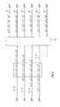
- Fig. 2 shows a schematic view of a passive optical filter device 25 having the spatial and spectral filter characteristics of a real 4 x 6 AWG, which can, of course, be realized as 4 x 6 AWG in the form of a photonic integrated circuit (PIC) or integrated optical circuit.
- the feeder fibers FF1 to FF6 shown in Fig. 2 may act as working or protection feeder fiber 17, 19 in Fig. 1 .
- the wavelengths ⁇ 1 1 to ⁇ 6 1 allow transparent optical paths to the ports at the right side of the passive optical filter device 25, which may be used as distribution ports 15 k of the RN 7 in Fig. 1 .
- the transparent paths may be used bidirectionally.
- the dashed lines on the left side of the passive optical filter device 25 in Fig. 2 indicate unused ports of a real AWG, which would theoretically be possible but are not realized at all or not externally accessible. The same may apply to the right side of the passive optical filter device 25 or AWG.
- the transparent optical paths between WDM port 13 2 and the distribution ports 15 2 to 15 6 are used.
- the wavelength ⁇ 6 2 would, in case of this non-ideal AWG, not be passed through to port 15 1 but to a "non-existing" or unusable port 15 7 .
- an additional wavelength ⁇ 0 2 is used instead of the unusable wavelengths ⁇ 6 2 to enable a transparent optical path between WDM port 13 2 and distribution port 15 1 .
- wavelength ⁇ 0 3 to ⁇ 5 3 are supplied to WDM port 15 3 , wavelength ⁇ 5 2 would not be usable, as the AWG defines no usable optical path therefore.
- an additional wavelength ⁇ 1 2 is used to establish a transparent optical path between WDM port 13 3 and distribution port 15 1 .
- wavelength ⁇ 0 3 can be used to establish a communication link between WDM port 13 3 and distribution port 15 2 .
- a cyclic passive optical filter device 25 e.g. in the form of a cyclic AWG
- the term “cylic” means that the filter device 25 shows essentially the same spatial and spectral filter properties in another (usually higher order) optical band.
- the downstream wavelengths may lie in the optical C band
- the upstream wavelengths may lie in the L band.
- Fig. 3 shows an embodiment of a PON 1 according to Fig. 1 in greater detail.
- each OLT 3 which serves both the task of combining the optical paths for the downstream wavelengths and the task of separating the paths for the upstream wavelengths (these optical paths still being physically identical)
- two filter devices 29 i or M x N AWGs 31 i may be used, each of which being provided in the optical path for the downstream wavelengths and in a physically separate path for the upstream wavelengths.
- the passive M x N optical filter devices 29 i are connected to the respective working feeder fiber 17 and to the respective protection feeder fiber 19 using the same WDM ports, which are used to connect the respective working feeder fiber 17 and protection feeder fiber 19 in the RN 7 (the WDM ports define the WDM working and protection ports of the OLTs).
- the WDM ports define the WDM working and protection ports of the OLTs.
- the OLTs in Fig. 3 are connected to the RN 7 using neighboring WDM ports of the passive optical filter devices 29 i or M x N AWGs 31 i .
- This is advantageous as in order to switch from a set of working wavelengths to a set of protection wavelengths in an OLT 3, a shift of a single grid spacing for each optical transmitter device is required, only.
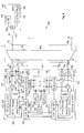
- Fig. 4 shows an embodiment of a PON 100 comprising a number of m OLTs 103, which are connected to n ONUs 105 via a remote node 7.
- the general structure is thus identical to the PON structure in Fig. 1 and 3 so that corresponding elements and features are referred to by identical reference signs as in Fig. 1 and 3 .
- Each OLT 103 comprises an array 140 of optical receiver devices.
- the first passive optical filter device 146 may be realized as a single M x N AWG 148.
- the filter device 146 or the AWG 148 must be able to appropriately demultiplex the upstream working and protection wavelengths created in the ONUs 105, i.e.
- the filter device 146 or the AWG 148 must be configured to define suitable transparent optical paths for the working and protection communication links established between the ONUs 105 and the respective OLT 103 and their respective receiver devices.
- a WDM working port 150 of the M x N AWG 148 is connected to an output port 154 of a directional coupler device 152, which separates the optical paths for receiving upstream working wavelengths (i.e. upstream optical channel working signals) supplied to the WDM working port 9 m of the respective OLT 103, wherein the WDM working port 9 m of the OLT 103 is connected to a WDM port 156 of the directional coupler device 152.
- An output port 164 of the directional coupler device 160 is connected to a WDM protection port 151 of the M x N AWG 148.
- the directional coupler device 152 is adapted to pass through upstream working wavelengths received at the WDM port 156 to the output port 154 and to pass through downstream working wavelengths created in the OLT 103, which are received at an input port 158 to the WDM port 152.
- the directional coupler device 160 is adapted to pass through upstream protection wavelengths received at the WDM port 162 to the output port 164 and to pass through downstream protection wavelengths created in the OLT 103, which are received at an input port 166, to the WDM port 162.
- the directional coupler devices 152, 160 can be realized as optical circulator devices. If different bands are used for the downstream and upstream working and protection wavelengths, e.g. if the downstream wavelengths are in the C band and the upstream wavelengths are in the L band, alternatively, an optical diplexer device can be used.
- Each OLT 103 further comprises an array 170 of tunable optical transmitter devices, e.g. tunable optical lasers.
- the first passive optical filter device 176 may be realized as a single M x N AWG 178.
- the tunable transmitter devices create downstream working or protection wavelengths, which are multiplexed by the AWG 178 and output at a WDM working port 180 or at a WDM protection port 181, depending on the respective wavelengths and the local input port 174 k to which the respective wavelengths are supplied.
- the WDM working port 180 is connected to the input port 158 of the optical directional coupler 152 and the WDM protection port 181 is connected to the input port 166 of the optical directional coupler 160.
- the M x N AWGs 148 and 178 must be adapted to the M x N AWG in the RN. It is, of course, possible to use specifically designed AWGs in order to match the corresponding requirements. However, the use of identical AWGs, at least with respect to their internal structure, is advantageous with respect to costs.
- Each OLT 103 further comprises a local control unit 182 and a control device 184.
- the control device 184 is adapted to control the optical transmitter devices, especially with respect to the wavelengths of the signal created, and the receiver devices.
- the control device 184 further receives data (not shown in the figures) and controls the transmitter devices in such a way that each working or protection wavelength, i.e. the respective optical signal created at this (carrier) wavelength, comprises the information according to the data to be transmitted at the respective wavelength or within the respective optical downstream working or protection signal.
- Switching from the downstream working channel signals to downstream protection signals in an OLT 103 is simply effected by switching the wavelengths in such a way that the protection path is used instead of the working path, i.e. the wavelengths are changed so that the respective signals are output at the WDM protection port 181 instead of at the WDM working port 180 of the AWG 178. Switching from the downstream protection channel signals to downstream working signals in an OLT 103 is achieved accordingly. These and other direct control tasks are carried out by the control device 184.
- the control device 184 may, in case that switching from the working path to the protection path is required, inform the ONUs accordingly, if the ONUs are not capable to detect at which wavelength the downstream communication link with a respective OLT is operated, e.g. as the ONUs comprise a broadband receiver device 186, as is the case in the embodiment according to Fig. 4 .
- the ONUs 105 comprise a photodiode that is capable of opto-electrically converting a received downstream (working or protection) channel signal at any wavelength. As an ONU 105 receives the information included in a downstream (working or protection) channel signal whether the communication link is a working or protection communication link (i.e.
- the ONUs 105 comprise tunable optical transmitter devices 188, too. These are controlled by an ONU control unit 190.
- the ONUs 105 in Fig. 4 comprise a directional coupler device 192 for combining and separating the downstream path and the upstream path as each ONU 105 is coupled to the RN 7 by a single distribution fiber, only.
- a directional coupler device 192 for combining and separating the downstream path and the upstream path as each ONU 105 is coupled to the RN 7 by a single distribution fiber, only.
- the directional coupler device 192 it can be referred to the description concerning the directional coupler devices 156, 162 in the OLTs 103.
- the dashed arrow in Fig. 4 indicates that it is also possible to supply the information concerning the wavelength of the upstream channel signal elsewise, e.g. via a management channel between an OLT or a central control entity (not shown), which monitors the availability of the working paths and protection path and transmits the information which path is to be used to the respective OLT and the ONUs.
- the working path is the optical path an optical channel (working or protection) signal takes between the respective transmitter device and receiver device, i.e. a downstream (working and protection) path comprises all optical waveguides and the optical paths through all (passive) optical elements between the output port of the respective transmitter device of the respective OLT and the input port of the receiver device of the respective ONU and an upstream (working or protection) path comprises all optical waveguides and the optical paths through all (passive) optical elements between the output port of the respective transmitter device of the respective ONU and the input port of the receiver device of the respective OLT.
- a downstream (working and protection) path comprises all optical waveguides and the optical paths through all (passive) optical elements between the output port of the respective transmitter device of the respective OLT and the input port of the receiver device of the respective ONU
- an upstream (working or protection) path comprises all optical waveguides and the optical paths through all (passive) optical elements between the output port of the respective transmitter device of the respective ONU and the input port of the receiver device of the respective OLT.
- each OLT 103 in Fig. 4 communicates with each other, especially to exchange information concerning the communication links (at least the downstream communication links) which are active between the respective OLT 103 and the ONUs 105.
- each OLT 103 receives the information which ONU 105 is actually not communicating with another OLT 103 and may thus be addressed by the respective OLT 103.
- This communication between the OLTs 103 in the embodiment according to Fig. 4 is necessary as each ONU 105 comprises a broadband receiver device 186. This does not allow simultaneously receiveing more than one optical channel signal (at what wavelength whatsoever) as the signals could not be separated.
- the local control units 182 may be configured in such a way that one of the local control units 182 acts as a master and assigns allowable (or available) communication links (between a respective OLT and the ONUs) to the other OLTs 103.
- the OLTs 103 use this information to establish a communication link between a selected transmitter device (which is capable of creating the required wavelength) and an available ONU 105, only.
- the master local control unit 182 decides which of the other OLTs 103 is to be preferred if more than one of the other OLTs 103 requests a communication link to the same ONU 105.
- a central control unit (see e.g. the embodiment according to Fig. 6 ) may be provided.
- the local control units 182 or the local control units and a central control unit form a common control device, which is adapted to control the OLTs 103 in such a way that allowable communication links (regardless whether these are working or protection communication links) are established between an ONU and one or more OLTs, only (more than one communication link between an ONU and two or more different OLTs are only allowable if the ONU receiver device is configured to separate downstream channel signals having different wavelengths).
- a central control unit may be comprised of a selected OLT instead of being a separate unit.
- the local control units 182 may also be comprised of the ONU control devices 184, the ONU control devices 184 being configured to take over the tasks of a local control unit 182.
- the OLTs 103 in Fig. 4 further comprise a wavelength locking device 194 adapted to receive a small portion of the optical power of at least one upstream working or protection channel signal.
- a wavelength locking device 194 adapted to receive a small portion of the optical power of at least one upstream working or protection channel signal.
- optical splitters are provided within the optical paths between the WDM working port 150 and the output port 154 of the optical splitter device 152 and the WDM protection port 151 and the output port 164 of the optical splitter device 160.
- the wavelength locking device 194 detects the optical power included in a selected upstream channel signal and supplies this information to the control device 184, which controls the suitable transmitter device 170 of the transmitter array in such a way that this information is transmitted to the respective ONU 105, which creates the respective upstream channel signal.
- the ONU can control the tunable transmitter device 188 in such a way that the signal wavelength matches best the wavelength defined by the passive optical filter devices 25 and 146 included in the RN 7 and the OLT 103, respectively.
- the OLT 103 may already determine a tuning information (i.e. the direction and amount of a wavelength shift required in the ONU in order to match the desired channel wavelength) and transmit this tuning information to the respective ONU 105.
- the wavelength locking device 194 may include a tunable receiver device so that the signal to be tuned can be selected from the incoming upstream channel signals.
- Fig. 5 shows a further embodiment of a PON 200 similar to the embodiment in Fig. 4 .
- the essential difference of the PON 200 in Fig. 5 from the PON 100 in Fig. 4 is the use of tunable receiver devices 286 in at least one of the ONUs 205.
- an ONU 205 is able to select between more than one communication links or downstream (working or protection) channel signals created by different OLTs 103. It would thus be possible to waive the requirement of coordinating the OLTs 103 with respect to available or allowable (downstream) communication links by providing a common control device (including the local and, as the case may be, a central control units 182).
- the common control device may collect the information of downstream channel signals for each of the ONUs 205 and transmit this information to the respective ONUs 205. In this way, an ONU 205 is not required to scan all possible wavelengths in order to determine which downstream channel signals are actually present.
- Fig. 6 shows a further embodiment of a PON 300 comprising OLTs 303, a remote node 7 and ONUs 105.
- OLTs 303 OLTs 303
- remote node 7 OLTs 303
- ONUs 105 OLTs 303
- elements and features that are identical to elements and features of the previously explained embodiments are referred to using identical reference signs.
- Each OLT 303 differs from the OLTs 103 in Fig. 4 and 5 in that reflective optical transmitter devices 340 are used instead of tunable transmitter devices 140.
- reflective optical transmitter devices 340 seeded reflective semiconductor optical amplifiers (seeded RSOAs) or reflective electro-absorption modulators (REAMs) may be used.
- RSOAs reflective semiconductor optical amplifiers
- RRMs reflective electro-absorption modulators
- a central seeding unit 310 is provided in order to seed the reflective optical transmitter devices 340 .
- the central seeding unit 310 is adapted to supply seeding light to an input port 314 of a first optical switch 312, which is controlled by the control device 184, the switch 312 having an open and a closed state.
- An output port 316 of the first optical switch is connected to a first port of an optical circulator device 318, which is configured to supply the seeding light via a second port of the optical circulator device 318 to the WDM working port 180 of the passive optical filter device 176 or M x N AWG 178, respectively.
- a third port of the optical circulator device 318 is connected to the input port 158 of the directional coupler device 152. In this way, the control device 184 can control the seeding light supplied to the input port 314 of the first optical switch 312 to be supplied to the WDM working port 180 of the AWG 178.
- the central seeding unit 310 is adapted to supply seeding light to an input port 322 of a second optical switch 320, which is controlled by the control device 184, too, the switch 320 having an open and a closed state.
- An output port 324 of the first optical switch is connected to a first port of an optical circulator device 326, which is configured to supply the seeding light via a second port of the optical circulator device 326 to the WDM protection port 181 of the passive optical filter device 176 or M x N AWG 178, respectively.
- a third port of the optical circulator device 320 is connected to the input port 166 of the directional coupler device 160. In this way, the control device 184 can control the seeding light supplied to the input port 322 of the first optical switch 320 to be supplied to the WDM protection port 181 of the AWG 178.
- each of the n output ports of the transmitter devices 340 is coupled to an optical shutter or switch 330.
- the optical switches may be combined to an array of switches as shown in Fig. 6 and may further be configured to be controllable by the OLT control device 184.
- the control device 184 is able to selectively activate or deactivate each of the reflective optical transmitter devices 340 by appropriately controlling the switches 312 and 322 and each of the switches 330 into a closed or open state.
- the central seeding unit 310 may comprise several seeding light sources 350.
- the seeding light sources may be identical or adapted to specifically create the working and protection wavelengths, only, that are required by the respective OLT 303 (see Fig. 2 ). Identical seeding light sources may be used for safety reasons as redundant seeding light sources.
- the output port of each seeding light source 350 is coupled to a switching device 352, which is adapted to perform the required switching actions.
- a simple alternative of a switching device may include a X x 1 switch, each of the X input ports of the X x 1 switch being connected to a respective output port of a dedicated seeding light source 350.
- the output port of the X x 1 switch may be connected to a 1 x P star coupler, each of the P output ports of the star coupler being connected to an output port of the switching device 352, each of which is coupled to an input port 314, 322 of a first or second optical switch 312, 320 of an OLT.
- the number X of output ports of the switching device 352 must match or be higher than the number of input ports 314, 322 of the first or second optical switches 312, 320 of the OLTs. In this respect, it shall be noted that it is not mandatory that each OLT has protection capability. In this case the elements of the protection path (including the respective second switch 320) may be omitted.
- the central seeding unit may include a local control unit 360 configured to communicate with the local control units 182 in the OLTs 303.
- the local control unit 360 controls the switching device 352 as regards which of the light sources 350 are to be connected to which of the P output ports.
- the local control unit 360 forms the common control device, which allows communication between the OLTs and, in case of the embodiment in Fig. 6 , the local control unit 360.
- the local control unit 360 may also serve as a central control unit and take over the respective tasks explained above.
- Fig. 7 shows an embodiment of a PON 400 comprising OLTs 403 using tunable optical transmitters 170, a remote node 7 and ONUs 405 comprising reflective optical transmitter devices 488, which are seeded via the OLTs 403.
- a central seeding unit 310 is provided, which may reveal the same properties than the central seeding unit in Fig. 6 .
- the light sources 350 are adapted to transmit seeding light in an optical band different from the band in which the downstream (working or protection) wavelengths lie. Otherwise the seeding light would interfere with the downstream wavelengths or downstream optical channel signals.
- the RN 7 must comprise a passive optical filter device having the properties of a cyclic M x N AWG, as the upstream and downstream wavelengths must lie in different optical bands.
- each OLT 403 comprises a first and a second selecting means 410, 412 for selecting working and protection seed wavelengths, respectively.
- the central seeding unit 310 supplies broadband seeding light of a selected seeding source 350 via the switching means 352, which is appropriately controlled by the local control unit 360 (not shown in Fig. 7 ; see Fig. 6 ), either to an input port 414 of the first selecting means 410 or to an input port 416 of the second selecting means 412.
- the selecting means 410 is configured to selectively output working seeding wavelengths at an output port 418 to a coupler device 422 provided in the protection path between the WDM working port 180 of the AWG 178 and the input port 158 of the directional coupler 152.
- the selecting means 412 is configured to selectively output protection seeding wavelengths at an output port 420 to a coupler device 424 provided in the protection path between the WDM protection port 181 of the AWG 178 and the input port 166 of the directional coupler 160.
- Each of the selecting means 410, 412 comprises an input AWG 426 and an output AWG 428.
- the input ports of the AWGs 426 define the input ports 414 and 416, respectively.
- These AWG filter and demultiplex the broadband light supplied to the input ports 414, 416 and supply the respective wavelengths to input ports of shutters or switches 428, which may be provided as shutter arrays as shown in Fig. 7 and which are controlled by the control device 184.
- the AWGs 426 are configured to create exactly the desired working or protection wavelengths needed for seeding the ONUs 405.
- the working and protection seeding wavelengths required for the respective OLT may be selected by providing a specifically 1 x N AWGs 426 for each OLT 403 or by using a 1 x (N+M-1) AWGs 426 capable of providing the complete set of N+M-1 (working and protection) wavelengths (or working and protection wavelengths) and to select the required wavelengths by appropriately controlling the switches 430.
- N+M-1 AWGs 426 or AWGs having a higher number of ports than N+M-1 and merely using the required ports producing the desired wavelengths
- the number of switches 426 must be N+M-1, too.
- any other passive optical filter device having the desired properties may be used.
- the output ports of the controllable switches 430 at which the desired wavelengths are output in case the respective switches are controlled into a closed state are connected to the output AWG 428, serve to combine the created and selected wavelengths to a single optical path beginning at the respective output port 418 and 420, respectively.
- any other passive optical device may be used, which is able to combine a respective number of optical paths to a single optical path for all of the desired wavelengths.
- the invention provides a PON structure using a RN comprising a passive optical filter device having the properties of a, as the case may be, cyclic M x N AWG.
- a set of n+m-1 wavelengths is sufficient in the feeder area between the OLTs and the RN in order to establish desired communication links between each of the ONUs and at least one selected OLT.
- This allows to realize open access PONs as the RN is configured to connect at least two OLTs.
- the OLTs may be owned or managed by different network providers. Due to the structure and functionality of the PON, one can select which OLT and thus which provider has access or which providers have access to a selected ONU. If ONUs with tunable receiver devices are used, each ONU is able to select the OLT a communication link shall be established with.
Landscapes
- Engineering & Computer Science (AREA)
- Computer Networks & Wireless Communication (AREA)
- Signal Processing (AREA)
- Optical Communication System (AREA)
Abstract
Description
- The invention relates to a passive optical network comprising at least two optical line terminals, a remote node and a plurality of optical node units. The invention further relates to an optical line terminal suitable for realizing such a passive optical network.
- Passive optical networks (PONs) are widely used in order to connect a plurality of optical network units (ONUs), which are typically located near a customer or within a customer's premises, to an optical line terminal (OLT). The OLT usually connects the PON with a further communication network. A PON usually comprises at least one remote node (RN), which is connected to the OLT at least via a working feeder fiber. If fiber protection is required in order to increase the availability of the PON, the RN can be additionally connected to the OLT via a protection feeder fiber. Each ONU is usually connected to the RN via a (working) distribution fiber. If fiber protection is required for this connection, too, each ONU or at least some ONUs may additionally be connected to the RN via a protection distribution fiber. Such a PON is disclosed in
EP 2 518 912 A1 - In this PON the RN is realized as a cyclic 1 x N arrayed waveguide grating (AWG) having a single wavelength division multiplex (WDM) port connected to the feeder fiber and a number of N distribution ports, each of which being connected to a distribution fiber. If fiber protection is required, the RN is realized as a cyclic 2 x N having an additional WDM port connected to a protection feederfiber. Instead of a single 2 x N AWG two separate 1 x N AWGs can be used within the RN or two separate RNs in order to connect the working and protection feeder fibers to the respective working and protection distribution fibers. However, these 1xN AWGs may reveal an identical internal structure as the 2 x N AWGs, wherein for connecting the working feeder fiber to the first AWG the first WDM port is used and for connecting the protection feeder fiber to the second AWG the second WDM port is used. That is, in case of the first AWG the first WDM port must be externally connectable, whereas in case of the second AWG the second WDM port must be externally connectable, only. This means, that the two AWGs have an internal identical structure of a 2 x N AWG but are used (and appear from an external view) as a 1 x N AWG. This facilitates the design and installation of the PON, especially as identically designed AWGs may be used in order to combine the downstream (working and protection) channel signals created by a respective transmitter array and to separate the upstream (working and protection) signals created the optical transmitter devices of active ONUs.
- The cyclic property of the AWG(s) is used to transmit downstream working and protection channel signals in a first optical band, e.g. the C band, and the upstream working and protection signals in a second optical band, e.g. the L band.
- In the OLT two broadband seeding light sources are connected to the working transmit path and the protection transmit path. Switching means are provided to either connect the working transmit path to a first WDM port or the protection transmit path to a second WDM port of the 2 x N AWG used in the transmitter arrangement. In this way only a selected one of the two seeding light sources is active. As the seeding light source is coupled to the desired WDM port of the 2 x N AWG of the transmitter arrangement, either downstream working channel signals at the respective downstream working wavelengths or downstream protection channel signals at the respective protection working wavelengths are created and supplied to a working WDM port or a protection WDM port of the OLT.
- It is a disadvantage of this PON structure that establishing a communication link to a desired ONUs requires access to the OLT, which, in general, is in the hands of a certain network provider. This PON design does not allow other providers to access the ONUs, i.e. to transmit own downstream channel signals to, and, if so desired, receive own upstream channel signals from the ONUs. Due to market requirements, future PON designs will have to provide open access capabilities. Also legislators or regulatory authorities may prescribe open access capabilities for future PONs with respect to the use of additional feeder fibers and/or wavelengths.
- It is thus an object of the present invention to provide a passive optical network, which makes it possible to access the optical node units from different optical line terminals, which may be in the hands of different providers, and which reveals a simple design and can be realized at low effort. It is a further object of the invention to provide an optical line terminal, which is suitable to be used for realizing such a passive optical network.
- The invention achieves these objects with the combinations of features of
patent claims 1 and 16, respectively. Further embodiments of the invention are apparent from the dependent claims. - The invention is based on the finding that a PON having certain open access features can easily be realized if at least two OLTs are coupled to a RN having a number of M WDM ports and a number of N distribution ports, which comprises a passive optical filter device adapted to realize the spectral and spatial filter property of an M x N arrayed waveguide grating. In this structure, the RN or the specific passive optical filter device comprised by the RN define the wavelengths of the transparent optical transmission paths between the OLT and each ONU, wherein each transparent optical transmission path comprises the respective working feeder fiber connecting the WDM working port of the respective OLT to a dedicated WDM port of the RN, the optical path for the respective wavelength within the RN and the respective distribution fiber connecting the respective distribution port of the RN and the communication port of the respective ONU.
- According to the invention, each optical line terminal is operable to unidirectionally or bidirectionally communicate with one or more selected or all ONUs using optical channel working signals. To achieve this, each OLT is operable to create and to supply to the working fiber respective downstream optical working channel signals. Each of the downstream optical channel working signals is created at a downstream working wavelength suitable for establishing, at the respective downstream working wavelength, a communication link between the OLT and the respective ONU. As stated above, the respective downstream working wavelength is defined by the filter properties of the RN.
- As each OLT is coupled to a dedicated WDM port of the RN, each transmission path between an ONU and the different OLTs requires a different wavelength. This behavior is caused by the filter properties of the RN, as each optical path between the M WDM ports and a selected one of the N distribution ports of the RN requires a different wavelength.
- Thus, this PON structure makes it possible to access the ONUs from different OLTs, which may be owned by different providers. In order to extend an existing PON as, e.g. described in
EP 2 518 912 A1 - As each transmission path between a WDM working or protection port of each OLT and a selected ONU has a different wavelength this PON structure allows multiple communication links between the ONUs and the OLTs, more precisely, simultaneously existing communication links between each OLT and a selected ONU.
- According to an embodiment of the invention in which fiber protection between an OLT and the RN is required, the respective OLT has a WDM protection port, which is connected to a dedicated remote node WDM port by a protection feeder fiber. The respective OLT is operable to create and to supply to the protection feeder fiber respective downstream optical channel protection signals, each of the downstream optical channel protection signals being created at a downstream protection wavelength suitable for establishing, at the respective downstream protection wavelength, a communication link between the OLT and the respective ONU via an optical protection transmission path comprising the protection feeder fiber, the RN and the respective distribution fiber.
- According to an alternative of this embodiment, the optical line terminals are arranged to switch, if a failure in at least one working communication link is detected, from communicating with the optical node units via the respective working communication links and the respective optical working transmission paths to communicating with the optical node units via the respective protection communication links and the respective optical protection transmission paths by creating downstream optical protection signals instead of creating downstream optical working signals.
- In a preferred embodiment, the passive optical filter device of the remote node is designed in such a way that the M WDM ports and the N distribution ports are neighboring ports with respect to the spectral and spatial filter property of the passive optical filter device, wherein downstream optical channel working or protection signals, which can be passed through from a given WDM port i, with i being an integer number between 1 and M, to neighboring distribution ports j and j+1, with j being an integer number between 1 and N-1, or upstream optical channel working or protection signals, which can be passed through from a given distribution port j, with j being an integer number between 1 and N, to neighboring WDM ports i and i+1, with i being an integer number between 1 and M-1, are spaced apart by the wavelength grid spacing defined by the grid filter property of the remote node or an integer multiple thereof.
- This is the normal property of a M x N AWG, if the M WMD ports and the N distribution ports, which are connected to the respective internal star coupler region of the AWG, are neighboring ports with respect to their spatial position in the star coupler region. Due to this neighboring spatial position in the star coupler region, two (spatially) neighboring ports also define pass-through paths between a selected port of the respective other side of the AWG (the side with the WDM ports or the distribution ports) having neighboring wavelengths (separated by a single grid spacing) with respect to the spectral grid filter property of the AWG, i.e. the neighboring wavelengths are spaced apart by a single grid spacing.
- However, it would also be possible to design an AWG in such a way that the ports are separated by a multiple of the grid spacing. Even an irregular spacing (with respect to the wavelength) between respective neighboring ports would be possible. A regular spacing, of course, facilitates the design of the PON, especially the design of the OLT.
- If the passive optical filter device of the RN reveals the property of an ideal AWG structure and if all possible distribution ports of the ideal AWG structure are used, it would be possible to use a set of N wavelengths to establish N working communication links between an OLT and the ONUs (each communication link between an ONU and the OLT having a wavelength defined by the RN), only, due to the ideal and fully cyclic behavior of the AWG (here the term "cyclic" is used for the following property of an ideal M x N AWG (with j=1 to M port at the one side of the AWG and k=1 to N ports at the other side of the AWG and generally N > M): the N neighboring wavelengths λ1 to λN input at port j=1 are output at ports k=1 to k=N in the given sequence, i.e. λ1 is output at port k=1, λ2 is output at port k=2, ... , λN is output at port k=N; the N neighboring wavelengths λ1 to λN input at port j=2 are output at ports k=2 to k=N and port k=1, i.e. λ1 is output at port k=2, λ2 is output at port k=3, ..., λN-1 is output at port k=N and λN is output at port k=1; etc; the N neighboring wavelengths λ1 to λN input at port j=M are output at ports k=M to k=N and ports k=1 to k=M-1, i.e. λ1 is output at port k=M, λ2 is output at port k=M+1, ... , λN-M+1 is output at port k=N, λN-M+2 is output at port k=1 and λN is output at port k=M-1).
- However, real AWGs having such an ideal behavior for a high number of ports (on the same side of the AWG) are difficult to manufacture. Thus, in practice, the possible ports at the edge or outer regions of the respective star coupler region remain unused. As a result, a higher number of wavelengths in the feeder area between the OLTs and the RN is necessary. The number of wavelengths nw can be calculated to be nw=n + (m - 1), wherein n is the number of ONUs to be connected (at the maximum n=N, i.e. n equals the number N of distribution ports) and m is the number of WDM ports of the RN connected to a feeder fiber, irrespective of the fact whether these are working or protection feeder fibers. If all OLTs are connected to the RN by a working feeder fiber and a protection feeder fiber, the maximum number of OLTs connectable to the RN is M/2 (more precisely, the integer value of M/2). It is, however, possible to connect one part of the OLTs via a working feeder fiber, only, and the other part of the OLTs via a working and a protection feeder fiber to the RN, depending on whether or not fiber protection is required between the respective OLTs and the RN.
- According to a preferred embodiment, the passive optical filter device of the remote node comprises or exclusively consists of an N x M arrayed waveguide grating. This is, of course the simplest way to realize the desired spatial and spectral filter properties of the RN.
- It is advantageous to connect the WDM working port and the WDM protection port of an optical line terminal to neighboring WDM ports of the remote node. In this way, the working wavelength and the protection wavelength of the working and transmission paths between the OLT and a selected ONU are neighboring wavelengths, too. If active tunable laser transmitter devices are used in the OLT, the switching from a respective working wavelength to a respective (neighboring) protection wavelength can be effected faster than in case of a greater distance between the two wavelengths, as each optical transmitter device must be controlled to shift the wavelength by a single grid spacing (or a multiple grid spacing, if one or more possible ports - in the internal AWG structure - have been skipped between the external AWG ports).
- According to another embodiment of the invention, the remote node comprises a passive optical filter device adapted to realize the function of an M x N cyclic arrayed waveguide grating or the passive optical filter device of the remote node comprises or exclusively consists of a cyclic N x M arrayed waveguide grating. This allows the use of different wavelength bands for upstream and downstream optical channel signals in order to realize bidirectional communication links. The OLTs may create downstream optical working or protection signals having wavelengths in a first band defined by the remote node passive optical filter device, and the ONUs may create upstream working or protection signals having wavelengths in a second band of the remote node passive optical filter device.
- In a specific embodiment, an OLT may comprise a first passive optical filter device within a transmit path of the OLT and a second passive optical filter device within a receive path of the OLT. The WDM working port of the OLT may, in this embodiment, be connected to a first WDM port of the first passive optical filter device and to a first WDM port of the second passive optical filter device via a first directional coupler, and the first and second passive optical filter devices may have, with respect to the first WDM ports, essentially identical spatial and, with respect to the wavelengths of the signals guided in the transmit and receive paths, identical spectral filter properties as the remote node passive optical filter device has with respect to the WDM port, which is connected, via the respective working feeder fiber, to the working WDM port of the respective optical line terminal.
- If, in this embodiment, fiber protection between the OLT and the RN is required, the WDM protection port of the OLT may be connected to a second WDM port of the first passive optical filter device and to a second WDM port of the second passive optical filter device via a second directional coupler, the first and second passive optical filter devices preferably having, with respect to the second WDM ports, essentially identical spatial and, with respect to the wavelengths of the signals guided in the transmit and receive paths, identical spectral filter properties as the remote node passive optical filter device has with respect to the WDM port, which is connected, via the respective protection feeder fiber, to the protection WDM port of the respective OLT.
- This enables to use passive optical filter devices in the remote node and in an OLT having an identical structure (and therefore having identical spatial and spectral filter properties), which simplifies the design of the OLTs and of the whole PON. Of course, in an OLT, the unused WDM ports - as compared to the passive optical filter device in the RN - do not need to be physically present.
- According to a further embodiment, the PON comprises a common control device, which is adapted to control the function of each OLT in such a way that the desired optical communication links between the OLT and the ONUs are established.
- The common control device may comprise local control units included in the OLTs, wherein the local control units are arranged to communicate with each other. In this embodiment, one of the local control units forming the common control device may act as a master unit, whereas the other local control units act as clients.
- Alternatively, the common control device may comprise local control units included in the optical line terminals and a central control unit, the local control units being arranged to communicate with the central control unit. The central control unit may, in this embodiment, act as a master, whereas the local control units act as clients.
- The OLTs may in this way communicate with each other or with the central control unit, especially in order to provide or receive information required concerning active and/or inactive communication links. This enables an OLT to decide whether or not it is allowed to establish a communication link to a selected ONU at the given wavelength (or at the given two wavelengths, if downstream and upstream channel signals reveal different wavelengths in different optical bands).
- The internal control functions of an OLT may be taken over by an OLT control unit. This OLT control unit may, for example, control the wavelengths of the optical transmitter devices, if tunable optical transmitter devices are used, including the shifting of the transmitter wavelengths in case of switching from optical channel working signals to optical channel protection signals and vice versa. If reflective optical transmitter devices are used in the OLT, the OLT control unit may control the seeding of the transmitter devices, including the control of optical switches for selecting the transmitter devices to be seeded or the control of optical switches for selecting a seeding light source from a group of at least two seeding sources.
- In another embodiment, the optical node units comprise a broadband receiver device and the common control device is adapted to control the at least two optical line terminals in such a way that only a single communication link is established at a time between an OLT and a selected ONU. This allows the use of simple and less expensive broadband receiver devices in the ONUs. In this embodiment, the local control unit of the OLT, which has already established a communication link to the selected ONU informs the other OLTs (more precisely, to the local control units of the other OLTs), either via direct communication or via the central communication device, that a communication link to this ONU already exists. Accordingly, the local control units of the other OLTs control the respective OLT in such a way that no further communication link (even if this had another wavelength) is established to the same ONU.
- Alternatively, the optical node units may comprise wavelength selective receiver devices. In that case, the common control device may be adapted to control
- the at least two OLTs in such a way that multiple communication links are establishable simultaneously, each between a selected OLT and the same selected ONU. For each of the multiple communication links a different wavelength is used due to the spectral and spatial filter property of the passive optical filter device of the RN.
- As explained above, each OLT may be adapted to be able to selectively establish communication links with each of the optical node units, preferably by selectively activating/deactivating N optical transmitter devices comprised within the OLT, which may be realized as laser transmitter devices or reflective transmitter devices.
- In a further embodiment, in each OLT reflective optical transmitter devices may be used instead of tunable transmitter devices. In order to seed these reflective optical transmitter devices a central seeding unit may be provided, which can be comprised by an OLT or provided separately. The central seeding unit comprises at least one seeding light source adapted to create a seeding light for the reflective optical transmitter devices. Each OLT may comprise optical switching means adapted to switch the seeding light either to a first or a second transmission path of the OLT, which may serve as a working transmission path, or to a protection transmission path. Further, the central seeding unit may comprise an optical switching means adapted to selectively connect one of at least two seeding light sources to a respective seeding input of a selected OLT. The seeding light sources may be provided as redundant seeding light sources or for creating seeding light in different optical bands.
- Likewise, the optical transmitter devices in the ONUs may be reflective optical transmitter devices and the central seeding unit may be configured to create and feed seeding light for the ONU transmitters to the OLTs. Also, in these embodiments, optical switching means may be provided to selectively connect one of at least two seeding light sources to a selected OLT or to a selected seeding input of an OLT, in case an OLT provides more than one communication path (especially a working path and a protection path), as explained above.
- In the following, the invention will be described with reference to the embodiments apparent from the drawing. In the drawing, the Figures show:
- Fig. 1
- a schematic block diagram of an embodiment of a PON comprising several OLTs and a plurality of ONUs which are connected via a RN including a cyclic M x N AWG;
- Fig. 2
- a diagram visualizing the principle of an M x N AWG as used for the RN in
Fig. 1 ; - Fig. 3
- a schematic block diagram of an embodiment of a PON as generally shown in
Fig. 1 , wherein the OLTs include cyclic M x N AWGs identical to the AWG used in the RN ; - Fig. 4
- a schematic block diagram of an embodiment of a PON similar to the embodiment in
Fig. 3 , wherein the OLTs further include a common control device comprising local control units in each OLT and wherein the ONUs comprise tunable optical transmitter devices; - Fig. 5
- a schematic block diagram of an embodiment of a PON similar to the embodiment in
Fig. 4 , the ONUs comprising tunable receiver devices; - Fig. 6
- a schematic block diagram of an embodiment of a PON similarto the embodiment in
Fig. 4 , wherein additionally a central seeding unit is provided for seeding reflective optical transmitter devices included in the OLTs; and - Fig. 7
- a schematic block diagram of an embodiment of a PON similar to the embodiment in
Fig. 4 , wherein the central seeding unit is provided for seeding reflective optical transmitter devices included in the ONUs. -
Fig. 1 shows aPON 1 comprisingm OLTs 3 andn ONUs 5, which are connected via aRN 7. EachOLT 3 has a WDM working port 9i (i=1..m) and a WDM protection port 11i (i=1..m). TheRN 7 has M WDM ports 13j (j=1..M) and N distribution ports 15k (k=1...N). Each WDM working port 9i is connected to a dedicated WDM port 13j by a workingfeeder fiber 17 and eachWDM protection port 11i is connected to a dedicated WDM port 13j+1 by aprotection feeder fiber 19. - Each
ONU 5 has acommunication port 21, which is connected to a dedicated distribution port 15k of the RN by adistribution fiber 23. InFig. 1 n=N ONUs 5 are connected to theRN 7. However, the number N of distribution ports 15k may be higher than the number n of actually connectedONUs 5 and the unconnected ports 15k may serve for extension purposes. - As shown in
Fig. 1 , at a maximum, m=M/2OLTs 3 can be connected to theRN 7, if fiber protection is required for each OLT (M being an even integer number). However, fiber protection is not mandatory. As at least a working connection via a workingfeeder fiber 17 is necessary in order to connect anOLT 3 to theRN 7, the maximum number ofOLTs 3 connectable to the RN 7 (without fiber protection in the feeder section) is M. It is, of course, also possible to connect one or more OLTs 3 via a working andprotection feeder fiber OLTs 3 via a workingfiber 17, only. - The
RN 7 comprises a passiveoptical filter device 25 adapted to realize a spectral and spatial filter property of an M x N arrayed waveguide grating (AWG). The passiveoptical filter device 25 defines the M WDM ports and the N distribution ports of theRN 7. Of course, the most direct way to realize the passiveoptical filter device 25 is to use an M x N arrayed waveguide grating 27, which is usually manufactured as photonic integrated circuit (PIC) or integrated optical circuit. - Generally, a PON, like the embodiment in
Fig. 1 , is capable of establishing bidirectional communication links between any selectedONU 5 and arespective OLT 3. It is, of course, also possible to establish unidirectional links, too, which may serve to carry unicast, multicast or broadcast traffic or data streams. As a passive optical filter device or an M x N AWG works bidirectionally, each transparent optical communication path between anOLT 3 and a selectedONU 5 may serve for both a respective downstream (working or protection) communication link and a respective upstream (working or protection) communication link. According to the properties of an M x N AWG, each optically transparent path between a WDM port 13j and a distribution port 15k is only possible for an optical channel signal (regardless of whether it is an upstream or downstream or working or protection channel signal) having a specific wavelength or bandwidth, respectively. - As, for the purpose of the invention and the present description, the nature of an optical channel signal that is used for the unidirectional (OLT to ONU or vice versa) communication or bidirectional communication is of no specific interest, it is referred to a channel signal by its specific optical wavelength λ, only.
- Each transparent optical path between a WDM port 13j and a distribution port 15k of an M x N AWG is assigned to a respective wavelength λk j, wherein each distribution port 15k and, thus each
ONU 5, can be reached from each WDM port, and thus from eachOLT 3, by a different, unique wavelength. - If an ideal M x
N AWG 27 is used as a passive optical filter device 25 (or a passive optical filter device having the same function but realized in a different way), a maximum of n=N channel signals at respective n different wavelengths λk j, spaced apart by a grid spacing of the spectral filter characteristic of the AWG, can be used to establish communication links between each of the WDM ports 13j and the n distribution ports 15k. If the index k=1 indicates the lowest wavelength and k=n the highest wavelength, a set of wavelengths λk 1 with k=1...n can be used to establish communication links between WDM port 131 and each of the distribution ports 151 to 15n. The same set of wavelengths can be used as wavelengths λk 2 with k=1...n to establish communication links between WDM port 132 and each of the distribution ports 152 to 15n and 151, and so forth. That is, using the same set of wavelengths at a second WDM port 13j+1 neighboring a first WDM port 13j results in a cyclic shift of the index of the distribution ports, i.e. to a cyclic shift of the associated distribution ports 15k to new associated distribution ports 15k+1. In case of an ideal AWG, k=n results in a cyclic shift to k=1. - However, as an ideal M x N AWG is difficult to manufacture for a higher number of (WDM or) distribution ports, it is necessary to use additional wavelengths in the feeder area. This approach will now be explained with regard to
Fig. 2 . -
Fig. 2 shows a schematic view of a passiveoptical filter device 25 having the spatial and spectral filter characteristics of a real 4 x 6 AWG, which can, of course, be realized as 4 x 6 AWG in the form of a photonic integrated circuit (PIC) or integrated optical circuit. At the left side, the ports which may be used as WDM port 13j of the passiveoptical filter device 25 inFig. 1 , (channel signals at) wavelengths λk 1, k=1...6, are supplied to WDM port 151 via a feeder fiber, designated as FF1. The feeder fibers FF1 to FF6 shown inFig. 2 may act as working orprotection feeder fiber Fig. 1 . The wavelengths λ1 1 to λ6 1 allow transparent optical paths to the ports at the right side of the passiveoptical filter device 25, which may be used as distribution ports 15k of theRN 7 inFig. 1 . Of course, the transparent paths may be used bidirectionally. - The dashed lines on the left side of the passive
optical filter device 25 inFig. 2 indicate unused ports of a real AWG, which would theoretically be possible but are not realized at all or not externally accessible. The same may apply to the right side of the passiveoptical filter device 25 or AWG. - If the ports 13j and 13j+1 and 15k and 15k+1 are neighboring ports and the same set of wavelengths λ1 2 to λ6 2 would be supplied to WDM port 132, the transparent optical paths between WDM port 132 and the distribution ports 152 to 156 are used. The wavelength λ6 2 would, in case of this non-ideal AWG, not be passed through to port 151 but to a "non-existing" or unusable port 157. Thus, an additional wavelength λ0 2 is used instead of the unusable wavelengths λ6 2 to enable a transparent optical path between WDM port 132 and distribution port 151.
- Likewise, if wavelengths λ0 3 to λ5 3 are supplied to WDM port 153, wavelength λ5 2 would not be usable, as the AWG defines no usable optical path therefore. Again, an additional wavelength λ1 2 is used to establish a transparent optical path between WDM port 133 and distribution port 151. Of course, wavelength λ0 3 can be used to establish a communication link between WDM port 133 and distribution port 152.
- This means that in case of a real M x N AWG, as compared to the use of an ideal M x N AWG , a number of m-1 additional wavelengths (m being the number of used WDM ports, regardless of whether these are used for protection or working communication links) are required to enable a communication link between each selected WDM port 13j and each of the distribution ports 15k. Thus, the total number of wavelengths is n+(m-1).
- In case of an exemplary PON revealing this structure and comprising a
RN 7 having eight WDM ports, which are used to connect four OLTs via a working and protection feeder fiber, and 40 distribution ports for connecting 40 ONUs, this leads to a set of 47 wavelengths in order to allow each OLT to communicate with each of the ONUs. Thus, in practical embodiments, in which the number n of ONUs is generally higher by several factors, the use of a non-ideal M x N AWG (or passive optical filter device) having the above properties is acceptable. Only rather few additional wavelengths, as compared to the total number of wavelengths in case of an ideal filter device, are required. - If the upstream wavelengths (i.e. the optical channel signals created by the ONUs and received by the respective OLT) shall be different from the downstream wavelengths (i.e. the optical channel signals created by the OLTs and received by the respective ONU) in a bidirectionally working PON, e.g. in order to avoid signal deterioration through reflections or scattering, a cyclic passive optical filter device 25 (e.g. in the form of a cyclic AWG) can be used. Here, the term "cylic" means that the
filter device 25 shows essentially the same spatial and spectral filter properties in another (usually higher order) optical band. For example, the downstream wavelengths may lie in the optical C band, whereas the upstream wavelengths may lie in the L band. -
Fig. 3 shows an embodiment of aPON 1 according toFig. 1 in greater detail. Here, essentially identical passive M x N optical filter devices 29i in the form of M x N AWGs 31i (i=1...m) are used in theOLTs 3 and in theRN 7. Even though a single M x N optical filter device 29i in the form of an M x N AWGs 31i is shown in eachOLT 3, which serves both the task of combining the optical paths for the downstream wavelengths and the task of separating the paths for the upstream wavelengths (these optical paths still being physically identical), two filter devices 29i or M x N AWGs 31i may be used, each of which being provided in the optical path for the downstream wavelengths and in a physically separate path for the upstream wavelengths. - As apparent from
Fig. 3 , the passive M x N optical filter devices 29i (e.g. in the form of M x N AWGs 31i) are connected to the respectiveworking feeder fiber 17 and to the respectiveprotection feeder fiber 19 using the same WDM ports, which are used to connect the respectiveworking feeder fiber 17 andprotection feeder fiber 19 in the RN 7 (the WDM ports define the WDM working and protection ports of the OLTs). This being the prerequisite for the correct set of n wavelengths being supplied to the dedicated WDM port in case of the use of a non-ideal M x N optical filter device 29i (e.g. in the form of a M x N AWGs 31i), as explained with regard toFig. 2 . Otherwise, it cannot be guaranteed that all of the wavelengths supplied to a selected WDM working orprotection port 9i, 11i are suitable to define a pass-through path connected to a respective local port of the filter device 29i or AWG 31i (an incorrect wavelength, which is supplied to a respective WDM port, would require to be output at an unused or physically not existing local port of the AWG). - As in
Fig. 1 the OLTs inFig. 3 are connected to theRN 7 using neighboring WDM ports of the passive optical filter devices 29i or M x N AWGs 31i. This is advantageous as in order to switch from a set of working wavelengths to a set of protection wavelengths in anOLT 3, a shift of a single grid spacing for each optical transmitter device is required, only. -
Fig. 4 shows an embodiment of aPON 100 comprising a number ofm OLTs 103, which are connected ton ONUs 105 via aremote node 7. The general structure is thus identical to the PON structure inFig. 1 and3 so that corresponding elements and features are referred to by identical reference signs as inFig. 1 and3 . As is the case for the embodiments inFig. 1 and3 , inFig. 4 the number M of WDM ports 13j of the RN 7 (defined by or identical with the WDM ports of the passiveoptical filter device 25 or theAWG 27, respectively) is M=2m, too, i.e. all WDM ports are connected to arespective OLT 103. - Each
OLT 103 comprises anarray 140 of optical receiver devices. Each input port 142k (k=1...n) of thearray 140 is connected to a local output port 144k (k=1...n) of a first passiveoptical filter device 146 having the same spatial and spectral filter properties as an M x N AWG. As apparent fromFig. 4 , the first passiveoptical filter device 146 may be realized as a single M xN AWG 148. Of course, thefilter device 146 or theAWG 148 must be able to appropriately demultiplex the upstream working and protection wavelengths created in theONUs 105, i.e. thefilter device 146 or theAWG 148 must be configured to define suitable transparent optical paths for the working and protection communication links established between theONUs 105 and therespective OLT 103 and their respective receiver devices. AWDM working port 150 of the M xN AWG 148 is connected to anoutput port 154 of adirectional coupler device 152, which separates the optical paths for receiving upstream working wavelengths (i.e. upstream optical channel working signals) supplied to the WDM working port 9m of therespective OLT 103, wherein the WDM working port 9m of theOLT 103 is connected to aWDM port 156 of thedirectional coupler device 152. - The WDM protection port 11i (i=1...m) of each
OLT 103 is connected to aWDM port 162 of a furtherdirectional coupler device 160. Anoutput port 164 of thedirectional coupler device 160 is connected to aWDM protection port 151 of the M xN AWG 148. - The
directional coupler device 152 is adapted to pass through upstream working wavelengths received at theWDM port 156 to theoutput port 154 and to pass through downstream working wavelengths created in theOLT 103, which are received at aninput port 158 to theWDM port 152. Likewise, thedirectional coupler device 160 is adapted to pass through upstream protection wavelengths received at theWDM port 162 to theoutput port 164 and to pass through downstream protection wavelengths created in theOLT 103, which are received at aninput port 166, to theWDM port 162. - If the upstream working and protection wavelengths lie in the same band as the downstream working and protection wavelengths, the
directional coupler devices - Each
OLT 103 further comprises anarray 170 of tunable optical transmitter devices, e.g. tunable optical lasers. Each output port 172k (k=1...n) of thearray 170 is connected to a local input port 174k (k=1...n) of a second passiveoptical filter device 176, preferably having the same spatial and spectral filter properties as an M x N AWG. As apparent fromFig. 4 , the first passiveoptical filter device 176 may be realized as a single M xN AWG 178. - The tunable transmitter devices create downstream working or protection wavelengths, which are multiplexed by the
AWG 178 and output at aWDM working port 180 or at aWDM protection port 181, depending on the respective wavelengths and the local input port 174k to which the respective wavelengths are supplied. TheWDM working port 180 is connected to theinput port 158 of the opticaldirectional coupler 152 and theWDM protection port 181 is connected to theinput port 166 of the opticaldirectional coupler 160. - As explained above with regard to
Fig. 2 and3 , the M xN AWGs - Each
OLT 103 further comprises alocal control unit 182 and acontrol device 184. Thecontrol device 184 is adapted to control the optical transmitter devices, especially with respect to the wavelengths of the signal created, and the receiver devices. Thecontrol device 184 further receives data (not shown in the figures) and controls the transmitter devices in such a way that each working or protection wavelength, i.e. the respective optical signal created at this (carrier) wavelength, comprises the information according to the data to be transmitted at the respective wavelength or within the respective optical downstream working or protection signal. - Switching from the downstream working channel signals to downstream protection signals in an
OLT 103 is simply effected by switching the wavelengths in such a way that the protection path is used instead of the working path, i.e. the wavelengths are changed so that the respective signals are output at theWDM protection port 181 instead of at theWDM working port 180 of theAWG 178. Switching from the downstream protection channel signals to downstream working signals in anOLT 103 is achieved accordingly. These and other direct control tasks are carried out by thecontrol device 184. - The
control device 184 may, in case that switching from the working path to the protection path is required, inform the ONUs accordingly, if the ONUs are not capable to detect at which wavelength the downstream communication link with a respective OLT is operated, e.g. as the ONUs comprise abroadband receiver device 186, as is the case in the embodiment according toFig. 4 . Here, theONUs 105 comprise a photodiode that is capable of opto-electrically converting a received downstream (working or protection) channel signal at any wavelength. As anONU 105 receives the information included in a downstream (working or protection) channel signal whether the communication link is a working or protection communication link (i.e. whether the optical working or protection path is used) it creates the respective upstream (working or protection) channel signal appropriately, i.e. the upstream wavelength is chosen accordingly. In order to enable the required wavelength switching in the ONUs, theONUs 105 comprise tunableoptical transmitter devices 188, too. These are controlled by anONU control unit 190. - The
ONUs 105 inFig. 4 comprise adirectional coupler device 192 for combining and separating the downstream path and the upstream path as eachONU 105 is coupled to theRN 7 by a single distribution fiber, only. As regards the function and possibilities to realize thedirectional coupler device 192, it can be referred to the description concerning thedirectional coupler devices OLTs 103. - The dashed arrow in
Fig. 4 indicates that it is also possible to supply the information concerning the wavelength of the upstream channel signal elsewise, e.g. via a management channel between an OLT or a central control entity (not shown), which monitors the availability of the working paths and protection path and transmits the information which path is to be used to the respective OLT and the ONUs. - At this point it shall be mentioned that the working path is the optical path an optical channel (working or protection) signal takes between the respective transmitter device and receiver device, i.e. a downstream (working and protection) path comprises all optical waveguides and the optical paths through all (passive) optical elements between the output port of the respective transmitter device of the respective OLT and the input port of the receiver device of the respective ONU and an upstream (working or protection) path comprises all optical waveguides and the optical paths through all (passive) optical elements between the output port of the respective transmitter device of the respective ONU and the input port of the receiver device of the respective OLT.
- The
local control units 182 included in eachOLT 103 inFig. 4 communicate with each other, especially to exchange information concerning the communication links (at least the downstream communication links) which are active between therespective OLT 103 and theONUs 105. In this way, eachOLT 103 receives the information whichONU 105 is actually not communicating with anotherOLT 103 and may thus be addressed by therespective OLT 103. This communication between theOLTs 103 in the embodiment according toFig. 4 is necessary as eachONU 105 comprises abroadband receiver device 186. This does not allow simultaneously receiveing more than one optical channel signal (at what wavelength whatsoever) as the signals could not be separated. - The
local control units 182 may be configured in such a way that one of thelocal control units 182 acts as a master and assigns allowable (or available) communication links (between a respective OLT and the ONUs) to theother OLTs 103. TheOLTs 103 use this information to establish a communication link between a selected transmitter device (which is capable of creating the required wavelength) and anavailable ONU 105, only. The masterlocal control unit 182 decides which of theother OLTs 103 is to be preferred if more than one of theother OLTs 103 requests a communication link to thesame ONU 105. - Of course, instead of using a master
local control unit 182, a central control unit (see e.g. the embodiment according toFig. 6 ) may be provided. It shall be understood that thelocal control units 182 or the local control units and a central control unit form a common control device, which is adapted to control theOLTs 103 in such a way that allowable communication links (regardless whether these are working or protection communication links) are established between an ONU and one or more OLTs, only (more than one communication link between an ONU and two or more different OLTs are only allowable if the ONU receiver device is configured to separate downstream channel signals having different wavelengths). - It should further be understood that a central control unit may be comprised of a selected OLT instead of being a separate unit. The
local control units 182 may also be comprised of theONU control devices 184, theONU control devices 184 being configured to take over the tasks of alocal control unit 182. - The
OLTs 103 inFig. 4 further comprise awavelength locking device 194 adapted to receive a small portion of the optical power of at least one upstream working or protection channel signal. For this purpose, optical splitters are provided within the optical paths between theWDM working port 150 and theoutput port 154 of theoptical splitter device 152 and theWDM protection port 151 and theoutput port 164 of theoptical splitter device 160. Thewavelength locking device 194 detects the optical power included in a selected upstream channel signal and supplies this information to thecontrol device 184, which controls thesuitable transmitter device 170 of the transmitter array in such a way that this information is transmitted to therespective ONU 105, which creates the respective upstream channel signal. In this way, the ONU can control thetunable transmitter device 188 in such a way that the signal wavelength matches best the wavelength defined by the passiveoptical filter devices RN 7 and theOLT 103, respectively. Of course, instead of transmitting information concerning the optical power of the upstream channel signal received, theOLT 103 may already determine a tuning information (i.e. the direction and amount of a wavelength shift required in the ONU in order to match the desired channel wavelength) and transmit this tuning information to therespective ONU 105. - In order to make it possible to tune the wavelength of an
ONU 105 while other ONUs are transmitting upstream channel signals, thewavelength locking device 194 may include a tunable receiver device so that the signal to be tuned can be selected from the incoming upstream channel signals. -
Fig. 5 shows a further embodiment of aPON 200 similar to the embodiment inFig. 4 . Thus, all identical elements and features are referred to using identical reference signs. The essential difference of thePON 200 inFig. 5 from thePON 100 inFig. 4 is the use oftunable receiver devices 286 in at least one of theONUs 205. In this way, anONU 205 is able to select between more than one communication links or downstream (working or protection) channel signals created bydifferent OLTs 103. It would thus be possible to waive the requirement of coordinating theOLTs 103 with respect to available or allowable (downstream) communication links by providing a common control device (including the local and, as the case may be, a central control units 182). However, the common control device may collect the information of downstream channel signals for each of theONUs 205 and transmit this information to therespective ONUs 205. In this way, anONU 205 is not required to scan all possible wavelengths in order to determine which downstream channel signals are actually present. -
Fig. 6 shows a further embodiment of aPON 300 comprisingOLTs 303, aremote node 7 andONUs 105. Again, elements and features that are identical to elements and features of the previously explained embodiments are referred to using identical reference signs. Thus, it is referred to the above explanation as concerns the nature and functionality of the respective elements and features. - Each
OLT 303 differs from theOLTs 103 inFig. 4 and5 in that reflectiveoptical transmitter devices 340 are used instead oftunable transmitter devices 140. As reflectiveoptical transmitter devices 340 seeded reflective semiconductor optical amplifiers (seeded RSOAs) or reflective electro-absorption modulators (REAMs) may be used. In order to seed the reflective optical transmitter devices 340 acentral seeding unit 310 is provided. Thecentral seeding unit 310 is adapted to supply seeding light to aninput port 314 of a firstoptical switch 312, which is controlled by thecontrol device 184, theswitch 312 having an open and a closed state. Anoutput port 316 of the first optical switch is connected to a first port of an optical circulator device 318, which is configured to supply the seeding light via a second port of the optical circulator device 318 to theWDM working port 180 of the passiveoptical filter device 176 or Mx N AWG 178, respectively. A third port of the optical circulator device 318 is connected to theinput port 158 of thedirectional coupler device 152. In this way, thecontrol device 184 can control the seeding light supplied to theinput port 314 of the firstoptical switch 312 to be supplied to theWDM working port 180 of theAWG 178. - Likewise the
central seeding unit 310 is adapted to supply seeding light to aninput port 322 of a secondoptical switch 320, which is controlled by thecontrol device 184, too, theswitch 320 having an open and a closed state. An output port 324 of the first optical switch is connected to a first port of anoptical circulator device 326, which is configured to supply the seeding light via a second port of theoptical circulator device 326 to theWDM protection port 181 of the passiveoptical filter device 176 or Mx N AWG 178, respectively. A third port of theoptical circulator device 320 is connected to theinput port 166 of thedirectional coupler device 160. In this way, thecontrol device 184 can control the seeding light supplied to theinput port 322 of the firstoptical switch 320 to be supplied to theWDM protection port 181 of theAWG 178. - As either working wavelengths or protection wavelengths shall be created by the
reflective transmitters 340, only one of theswitches - In the
OLT 303 according toFig. 6 each of the n output ports of thetransmitter devices 340 is coupled to an optical shutter orswitch 330. The optical switches may be combined to an array of switches as shown inFig. 6 and may further be configured to be controllable by theOLT control device 184. Thus, thecontrol device 184 is able to selectively activate or deactivate each of the reflectiveoptical transmitter devices 340 by appropriately controlling theswitches switches 330 into a closed or open state. - As shown in
Fig. 6 , thecentral seeding unit 310 may comprise several seedinglight sources 350. The seeding light sources may be identical or adapted to specifically create the working and protection wavelengths, only, that are required by the respective OLT 303 (seeFig. 2 ). Identical seeding light sources may be used for safety reasons as redundant seeding light sources. The output port of each seedinglight source 350 is coupled to aswitching device 352, which is adapted to perform the required switching actions. A simple alternative of a switching device may include a X x 1 switch, each of the X input ports of the X x 1 switch being connected to a respective output port of a dedicated seedinglight source 350. The output port of the X x 1 switch may be connected to a 1 x P star coupler, each of the P output ports of the star coupler being connected to an output port of theswitching device 352, each of which is coupled to aninput port optical switch switching device 352 must match or be higher than the number ofinput ports optical switches - The central seeding unit may include a
local control unit 360 configured to communicate with thelocal control units 182 in theOLTs 303. Thelocal control unit 360 controls theswitching device 352 as regards which of thelight sources 350 are to be connected to which of the P output ports. Together with thelocal control units 182, which may be included within the OLTs, thelocal control unit 360 forms the common control device, which allows communication between the OLTs and, in case of the embodiment inFig. 6 , thelocal control unit 360. As apparent fromFig. 6 , thelocal control unit 360 may also serve as a central control unit and take over the respective tasks explained above. -
Fig. 7 shows an embodiment of aPON 400 comprisingOLTs 403 using tunableoptical transmitters 170, aremote node 7 andONUs 405 comprising reflectiveoptical transmitter devices 488, which are seeded via theOLTs 403. For this purpose, acentral seeding unit 310 is provided, which may reveal the same properties than the central seeding unit inFig. 6 . However, as seeding of theONUs 405 is required, thelight sources 350 are adapted to transmit seeding light in an optical band different from the band in which the downstream (working or protection) wavelengths lie. Otherwise the seeding light would interfere with the downstream wavelengths or downstream optical channel signals. For this reason, theRN 7 must comprise a passive optical filter device having the properties of a cyclic M x N AWG, as the upstream and downstream wavelengths must lie in different optical bands. - As selective seeding is required for a selected
ONU 405 from a selectedOLT 403, it is necessary to provide appropriate selecting means in theOLTs 405. As apparent fromFig. 7 , eachOLT 403 comprises a first and a second selecting means 410, 412 for selecting working and protection seed wavelengths, respectively. - For providing working seeding wavelengths the
central seeding unit 310 supplies broadband seeding light of a selectedseeding source 350 via the switching means 352, which is appropriately controlled by the local control unit 360 (not shown inFig. 7 ; seeFig. 6 ), either to aninput port 414 of the first selecting means 410 or to aninput port 416 of the second selecting means 412. The selecting means 410 is configured to selectively output working seeding wavelengths at anoutput port 418 to acoupler device 422 provided in the protection path between theWDM working port 180 of theAWG 178 and theinput port 158 of thedirectional coupler 152. The selecting means 412 is configured to selectively output protection seeding wavelengths at anoutput port 420 to acoupler device 424 provided in the protection path between theWDM protection port 181 of theAWG 178 and theinput port 166 of thedirectional coupler 160. - Each of the selecting means 410, 412 comprises an
input AWG 426 and anoutput AWG 428. The input ports of theAWGs 426 define theinput ports input ports switches 428, which may be provided as shutter arrays as shown inFig. 7 and which are controlled by thecontrol device 184. Of course, theAWGs 426 are configured to create exactly the desired working or protection wavelengths needed for seeding theONUs 405. The working and protection seeding wavelengths required for the respective OLT may be selected by providing a specifically 1 xN AWGs 426 for eachOLT 403 or by using a 1 x (N+M-1)AWGs 426 capable of providing the complete set of N+M-1 (working and protection) wavelengths (or working and protection wavelengths) and to select the required wavelengths by appropriately controlling theswitches 430. Of course, if 1 x (N+M-1)AWGs 426 are used (or AWGs having a higher number of ports than N+M-1 and merely using the required ports producing the desired wavelengths) the number ofswitches 426 must be N+M-1, too. Instead of aninput AWG 426 any other passive optical filter device having the desired properties may be used. - The output ports of the
controllable switches 430, at which the desired wavelengths are output in case the respective switches are controlled into a closed state are connected to theoutput AWG 428, serve to combine the created and selected wavelengths to a single optical path beginning at therespective output port AWG 428 any other passive optical device may be used, which is able to combine a respective number of optical paths to a single optical path for all of the desired wavelengths. - As a summary, the invention provides a PON structure using a RN comprising a passive optical filter device having the properties of a, as the case may be, cyclic M x N AWG. A set of n+m-1 wavelengths is sufficient in the feeder area between the OLTs and the RN in order to establish desired communication links between each of the ONUs and at least one selected OLT. This allows to realize open access PONs as the RN is configured to connect at least two OLTs. The OLTs may be owned or managed by different network providers. Due to the structure and functionality of the PON, one can select which OLT and thus which provider has access or which providers have access to a selected ONU. If ONUs with tunable receiver devices are used, each ONU is able to select the OLT a communication link shall be established with.
-
- 1
- PON
- 3
- OLT
- 5
- ONU
- 7
- RN
- 9i
- WDM working port (i=1..m)
- 11i
- WDM protection port (i=1..m)
- 13j
- WDM port (i=1..M)
- 15k
- distribution port ki=1..N)
- 17
- working feeder fiber
- 19
- protection feeder fiber
- 21
- communication port
- 23
- distribution fiber
- 25
- passive optical filter device
- 27
- N x M AWG
- 29i
- M x N passive optical filter device (i=1...m)
- 31i
- M x N AWG (i=1...m)
- 100
- PON
- 103
- OLT
- 105
- ONU
- 140
- array of optical transmitter devices
- 142k
- input port (k=1...n)
- 144k
- local output port (k=1...n)
- 146
- passive optical filter device
- 148
- M
x N AWG 148 - 150
- WDM working port
- 151
- WDM protection port
- 152
- directional coupler device
- 154
- output port of
directional coupler device 152 - 156
- WDM port of
directional coupler device 152 - 158
- input port of
directional coupler device 152 - 160
- directional coupler device
- 162
- WDM port of
directional coupler device 160 - 164
- output port of
directional coupler device 160 - 166
- input port of
directional coupler device 160 - 170
- tunable optical transmitter devices
- 172k
- output port (k=1...n)
- 174k
- local input port (k=1...n)
- 176
- passive optical filter device
- 178
- M
x N AWG 178 - 180
- WDM working port
- 181
- WDM protection port
- 182
- local control unit
- 184
- control device
- 186
- broadband receiver device
- 188
- tunable transmitter device
- 190
- ONU control unit
- 192
- directional coupler device
- 200
- PON
- 205
- ONU
- 286
- reflective transmitter device
- 300
- PON
- 303
- OLT
- 310
- central seeding unit
- 312
- first optical switch
- 314
-
input port 314 of firstoptical switch 312 - 316
-
output port 316 of firstoptical switch 312 - 318
- optical circulator device
- 320
- second
optical switch 320 - 322
-
input port 322 of secondoptical switch 320 - 324
- output port 324 of second
optical switch 320 - 326
- optical circulator device
- 330
- optical switch
- 340
- reflective optical transmitter devices
- 350
- seeding light source
- 352
- switching device
- 360
- local control unit
- 400
- PON
- 403
- OLT
- 405
- ONU
- 410
- first selecting means
- 412
- second selecting means
- 414
- input port of first selecting
means 410 - 416
- input port of the second selecting means 412
- 418
- output port of first selecting
means 410 - 420
- output port of the second selecting means 412
- 422
- coupler device
- 424
- coupler device
- 426
- input AWG
- 428
- output AWG
- 430
- switches
- 488
- reflective optical transmitter devices
- m
- number of OLTs
- n
- number of ONUs
- M
- number of WDM ports of AWGs
- N
- number of distribution ports / number of local ports of AWGs
- P
- number of output ports of central seeding device
Claims (17)
- A passive optical network comprising at least two optical line terminals (3, 103, 303, 403), a remote node (7) and a plurality of optical node units (5, 105, 205, 405),(a) each optical line terminal (3, 103, 303, 403) having a WDM working port (9i), the remote node (7) having a predetermined number of M WDM ports (13j) and a predetermined number of N distribution ports (15k), and each optical node unit (5, 105, 205, 405) having a communication port (21k),(b) each optical line terminal WDM working port (13j) being connected to a dedicated remote node WDM port (13j) by a respective working feeder fiber (17), and each optical node unit communication port (21k) being connected to a dedicated remote node distribution port (15k) by a respective distribution fiber (23),(c) the remote node (7) comprising a passive optical filter device (25) adapted to realize a spectral and spatial filter property of an M x N arrayed waveguide grating, the passive optical filter device (25) defining the M WDM ports (13j) and the N distribution ports (15k), and(d) each optical line terminal (3, 103, 303, 403) being operable to unidirectionally or bidirectionally communicate with one or more selected or all optical node units (5, 105, 205, 405) using optical channel working signals, wherein each optical line terminal (3, 103, 303, 403) is operable to create and to supply to the working fiber (17) respective downstream optical working channel signals, each of the downstream optical channel working signals being created at a downstream working wavelength suitable for establishing, at the respective downstream working wavelength, a communication link between the optical line terminal (3, 103, 303, 403) and the respective optical node unit (5, 105, 205, 405) via an optical working transmission path comprising the working feeder fiber (17), the remote node (7) and the respective distribution fiber (23).
- A passive optical network according to claim 1, characterized in that one or more or all optical line terminals (3, 103, 303, 403) have a WDM protection port (9i), which is connected to a remote node WDM port (13j) by a respective protection feeder fiber (19), and that each optical line terminal (3, 103, 303, 403) is operable to create and to supply to the protection feeder fiber (19) respective downstream optical channel protection signals, each of the downstream optical channel protection signals being created at a downstream protection wavelength suitable for establishing, at the respective downstream protection wavelength, a communication link between the optical line terminal (3, 103, 303, 403) and the respective optical node unit (5, 105, 205, 405) via an optical protection transmission path comprising the protection feeder fiber (19), the remote node (7) and the respective distribution fiber (23).
- A passive optical network according to claim 2, characterized in that the optical line terminals (3, 103, 303, 403) are arranged to switch, if a failure in at least one working communication link is detected, from communicating with the optical node units (5, 105, 205, 405) via the respective working communication links and the respective optical working transmission paths to communicating with the optical node units (5, 105, 205, 405) via the respective protection communication links and the respective optical protection transmission paths by creating downstream optical protection signals instead of creating downstream optical working signals.
- A passive optical network according to one of the preceding claims, characterized in(a) that the passive optical filter device (25) of the remote node (7) is designed in such a way that the M WDM ports (13j) and the N distribution ports (15k) are neighboring ports with respect to the spectral and spatial filter property of the passive optical filter device (25),(b) wherein respective two downstream optical channel working or protection signals, which can be passed through from a given WDM port (13j) j, with j being an integer number between 1 and M, to neighboring distribution ports (15k) k and k+1, with k being an integer number between 1 and N-1, or respective two upstream optical channel working or protection signals, which can be passed through from a given distribution port (15k) k, with k being an integer number between 1 and N, to neighboring WDM ports (13j) j and j+1, with j being an integer number between 1 and M-1, are spaced apart, with respect to their wavelengths, by the wavelength grid spacing defined by the grid filter property of the remote node or an integer multiple thereof.
- A passive optical network according to one of the preceding claims, characterized in that the passive optical filter device (25) of the remote node (7) comprises or exclusively consists of an N x M arrayed waveguide grating (27).
- A passive optical network according to one of the preceding claims, characterized in that the WDM working port (9i) and the WDM protection port (11i) of an optical line terminal (3, 103, 303, 403) are connected to neighboring WDM ports (13j) of the remote node (7).
- A passive optical network according to one of the preceding claims, characterized in that the remote node (7) comprises a passive optical filter device (25) adapted to realize the function of an M x N cyclic arrayed waveguide grating or that the passive optical filter device (25) of the remote node (7) comprises or exclusively consists of a cyclic N x M arrayed waveguide grating (27), that the optical line terminals (3, 103, 303, 403) are arranged to create downstream optical working or protection signals having wavelengths in a first band defined by the remote node passive optical filter device (25), and that the optical node units (5, 105, 205, 405) are arranged to create upstream working or protection signals having wavelengths in a second band of the remote node passive optical filter device (25).
- A passive optical network according to one of the preceding claims, characterized in that an optical line terminal (103, 303, 403) comprises a first passive optical filter device (176) within a transmit path of the optical line terminal (103, 303, 403) and a second passive optical filter device (146) within a receive path of the optical line terminal (103, 303, 403), that the WDM working port (9i) is connected to a first WDM port (180) of the first passive optical filter device (176) and to a first WDM port (150) of the second passive optical filter device (146) via a first directional coupler (152), and that the first (176) and second (146) passive optical filter devices have, with respect to the first WDM ports (180; 150), essentially identical spatial and, with respect to the wavelengths of the signals guided in the transmit and receive paths, identical spectral filter properties as the remote node passive optical filter device (25) has with respect to the WDM port (13j), which is connected, via the respective working feeder fiber (17), to the working WDM port (9i) of the optical line terminal (103, 303, 403).
- A passive optical network according to claims 2 and 8, characterized in that in the respective optical line terminal (103, 303, 403) the WDM protection port (11i) is connected to a second WDM port (181) of the first passive optical filter device (176) and to a second WDM port (151) of the second passive optical filter device (146) via a second directional coupler (160), the first (176) and second (146) passive optical filter devices preferably having, with respect to the second WDM ports (181; 151), essentially identical spatial and, with respect to the wavelengths of the signals guided in the transmit and receive paths, identical spectral filter properties as the remote node passive optical filter device (25) has with respect to the WDM port (13j+1), which is connected, via the respective protection feeder fiber (19), to the protection WDM port (11i) of the respective optical line terminal (103, 303, 403).
- A passive optical network according to one of the preceding claims, characterized in that the passive optical network (100, 200, 300, 400) comprises a common control device (182, 184, 360), which is adapted to control the function of each optical line terminal (103, 303, 403) in such a way that the desired optical communication links between the optical line terminals and the optical node units (5, 105, 205, 405) are established.
- A passive optical network according to claim 10, characterized in that the common control device comprises local control units (182) included in the optical line terminals (103, 303, 403), wherein the local control units (182) are arranged to communicate with each other.
- A passive optical network according to claim 9, characterized in that the common control device comprises local control units (182) included in the optical line terminals (103, 303, 403) and a central control unit (360), the local control units (182) being arranged to communicate with the central control unit (360).
- A passive optical network according to one of claims 10 to 12, characterized in that the optical node units (5, 105, 405) comprise a broadband receiver device (186) and that the common control device is adapted to control the at least two optical line terminals (3, 103, 303, 403) in such a way that only a single communication link is establishable at a time between an optical line terminal (3, 103, 303, 403) and a selected optical node unit (5, 105, 405).
- A passive optical network according to one of claims 10 to 12, characterized in that the optical node units (205) comprise a wavelength selective receiver device (286) and that the common control device is adapted to control the at least two optical line terminals (3, 103, 303, 403) in such a way that multiple communication links are establishable at a time each between a selected optical line terminal (3, 103, 303, 403) and the same selected optical node unit (205), the multiple communication links using different wavelengths due to the spectral and spatial filter property of the passive optical filter device (25) of the remote node (7).
- A passive optical network according to one of the preceding claims, characterized in that each optical line terminal (3, 103, 303, 403) is adapted to be able to selectively establish communication links with each of the optical node units (5, 105, 405), preferably by selectively activating/deactivating N transmitter devices, which may be realized as laser transmitter devices (170) or reflective transmitter devices (340).
- A passive optical network according to one of the preceding claims, characterized in that the optical transmitter devices (340) of the optical line terminals (303) and/or the optical transmitter devices (188) of the optical node units (105) are reflective transmitter devices, and that a central seeding unit (310) is provided which is configured to create a seeding light and to feed the seeding light to each optical line terminal (303, 403), each optical line terminal (303, 403) being configured to guide the seeding light to the reflective optical transmitter devices (340) of the optical line terminal (303) and/or to the optical transmission path in the direction towards the optical node units.
- An optical line terminal (3, 103, 303, 403) for realizing a passive optical network (1, 100, 200, 300, 400) according to one of the preceding claims(a) comprising optical transmitter devices (170, 340) operable to create downstream optical working channel signals,(b) each of the downstream optical channel working signals being created at a downstream working wavelength suitable for establishing, at the respective downstream working wavelength, a communication link between the optical line terminal (3, 103, 303, 403) and a selected optical node unit (5, 105, 405) via a remote node (7),
characterized in(c) that the optical line terminal (3, 103, 303, 403) is configured to communicate with a central control unit (360) or one or more other optical line terminals (3, 103, 303, 403) in order to provide or receive information required concerning active and/or inactive communication links.
Priority Applications (2)
| Application Number | Priority Date | Filing Date | Title |
|---|---|---|---|
| EP14000708.9A EP2913947B1 (en) | 2014-02-27 | 2014-02-27 | Passive optical network and optical line terminal |
| US14/616,575 US20150244494A1 (en) | 2014-02-27 | 2015-02-06 | Passive Optical Network and Optical Line Terminal |
Applications Claiming Priority (1)
| Application Number | Priority Date | Filing Date | Title |
|---|---|---|---|
| EP14000708.9A EP2913947B1 (en) | 2014-02-27 | 2014-02-27 | Passive optical network and optical line terminal |
Publications (2)
| Publication Number | Publication Date |
|---|---|
| EP2913947A1 true EP2913947A1 (en) | 2015-09-02 |
| EP2913947B1 EP2913947B1 (en) | 2019-11-27 |
Family
ID=50190155
Family Applications (1)
| Application Number | Title | Priority Date | Filing Date |
|---|---|---|---|
| EP14000708.9A Active EP2913947B1 (en) | 2014-02-27 | 2014-02-27 | Passive optical network and optical line terminal |
Country Status (2)
| Country | Link |
|---|---|
| US (1) | US20150244494A1 (en) |
| EP (1) | EP2913947B1 (en) |
Cited By (1)
| Publication number | Priority date | Publication date | Assignee | Title |
|---|---|---|---|---|
| WO2021148118A1 (en) * | 2020-01-22 | 2021-07-29 | Telefonaktiebolaget Lm Ericsson (Publ) | Optical routing |
Families Citing this family (8)
| Publication number | Priority date | Publication date | Assignee | Title |
|---|---|---|---|---|
| WO2015144195A1 (en) * | 2014-03-24 | 2015-10-01 | Telefonaktiebolaget L M Ericsson (Publ) | Protection switching across interconnecting node |
| EP2928091A1 (en) * | 2014-03-31 | 2015-10-07 | Alcatel Lucent | Method of receiving a wavelength-division multiplexed optical upstream signal in an optical access network |
| US9628172B2 (en) * | 2014-10-13 | 2017-04-18 | Ciena Corporation | Optimization of photonic services with colorless and directionless architecture |
| WO2016110933A1 (en) * | 2015-01-05 | 2016-07-14 | 三菱電機株式会社 | Communication device and method for carrier frequency control |
| CN107547165B (en) * | 2016-06-24 | 2019-07-05 | 中兴通讯股份有限公司 | Optical line terminal, method for transmitting signals and device |
| US11178472B2 (en) | 2018-06-08 | 2021-11-16 | Nokia Solutions And Networks Oy | Monitoring multiple passive optical networks |
| EP3937401B1 (en) * | 2020-07-07 | 2023-04-12 | ADVA Optical Networking SE | Method and device for migrating data traffic from an existing optical wdm transmission system to a new optical wdm transmission system |
| CN115802210B (en) * | 2022-10-18 | 2025-09-26 | 中国电信股份有限公司 | Optical line terminal cutover method, device, and electronic equipment |
Citations (3)
| Publication number | Priority date | Publication date | Assignee | Title |
|---|---|---|---|---|
| US20090297152A1 (en) * | 2008-05-27 | 2009-12-03 | Nortel Networks Limited | Wdm pon protection scheme using a dual port arrayed waveguide grating (awg) |
| WO2011134507A1 (en) * | 2010-04-28 | 2011-11-03 | Telefonaktiebolaget L M Ericsson (Publ) | Optical access network |
| EP2518912A1 (en) * | 2011-04-29 | 2012-10-31 | ADVA AG Optical Networking | Optical line termination node and passive optical network |
Family Cites Families (13)
| Publication number | Priority date | Publication date | Assignee | Title |
|---|---|---|---|---|
| FI20012570A0 (en) * | 2001-12-21 | 2001-12-21 | Nokia Corp | Optical transmission network |
| KR100610245B1 (en) * | 2004-11-16 | 2006-08-09 | 한국과학기술원 | Communication recovery system of wavelength division multiplexing passive optical subscriber network |
| US8369706B2 (en) * | 2006-07-18 | 2013-02-05 | Novera Optics, Inc. | Open access service model using WDM-PON |
| DE102008005942A1 (en) * | 2008-01-24 | 2009-07-30 | Adva Ag Optical Networking | Method for protecting a passive optical transmission network and passive optical transmission network with a corresponding protection mechanism |
| KR101253325B1 (en) * | 2008-12-22 | 2013-04-12 | 한국전자통신연구원 | Method for LAN emulation in WDM-PON |
| PE20120909A1 (en) * | 2009-05-19 | 2012-08-19 | Bioproperties Pty Ltd | VACCINE STRAIN OF MYCOPLASMA HYOPNEUMONIAE SENSITIVE TO TEMPERATURE AND USES OF THE SAME |
| US8285144B2 (en) * | 2009-07-30 | 2012-10-09 | Jds Uniphase Corporation | Optical device for rearranging wavelength channels |
| US8472805B2 (en) * | 2010-05-26 | 2013-06-25 | Google Inc. | Tunable multi-wavelength optical transmitter and transceiver for optical communications based on wavelength division multiplexing |
| EP2525517B1 (en) * | 2011-05-20 | 2016-05-04 | ADVA Optical Networking SE | An optical wavelength division multiplex (WDM) transmission system, especially a WDM passive optical network |
| US9031408B2 (en) * | 2011-06-09 | 2015-05-12 | Telefonaktiebolaget L M Ericsson (Publ) | Method for fast wavelength division multiplexing (WDM) passive optical network (PON) initialization in heterogeneous networks |
| US9020349B2 (en) * | 2012-03-28 | 2015-04-28 | Telefonaktiebolaget L M Ericsson (Publ) | Arrangement at a remote node, a remote node, a central office and respective methods therein for supervision of a wavelength division multiplexed passive optical network |
| US9425918B2 (en) * | 2013-04-19 | 2016-08-23 | Futurewei Technologies, Inc. | Flexible TWDM PON with load balancing and power saving |
| WO2014198017A1 (en) * | 2013-06-09 | 2014-12-18 | 华为技术有限公司 | Method and device for virtualization passive optical network and passive optical network virtualization system |
-
2014
- 2014-02-27 EP EP14000708.9A patent/EP2913947B1/en active Active
-
2015
- 2015-02-06 US US14/616,575 patent/US20150244494A1/en not_active Abandoned
Patent Citations (3)
| Publication number | Priority date | Publication date | Assignee | Title |
|---|---|---|---|---|
| US20090297152A1 (en) * | 2008-05-27 | 2009-12-03 | Nortel Networks Limited | Wdm pon protection scheme using a dual port arrayed waveguide grating (awg) |
| WO2011134507A1 (en) * | 2010-04-28 | 2011-11-03 | Telefonaktiebolaget L M Ericsson (Publ) | Optical access network |
| EP2518912A1 (en) * | 2011-04-29 | 2012-10-31 | ADVA AG Optical Networking | Optical line termination node and passive optical network |
Non-Patent Citations (1)
| Title |
|---|
| CALVIN C K CHAN ET AL: "Novel network architectures for survivable WDM passive optical networks", OPTICAL COMMUNICATION, 2008. ECOC 2008. 34TH EUROPEAN CONFERENCE ON, IEEE, PISCATAWAY, NJ, USA, 21 September 2008 (2008-09-21), pages 1 - 4, XP031381168, ISBN: 978-1-4244-2227-2 * |
Cited By (1)
| Publication number | Priority date | Publication date | Assignee | Title |
|---|---|---|---|---|
| WO2021148118A1 (en) * | 2020-01-22 | 2021-07-29 | Telefonaktiebolaget Lm Ericsson (Publ) | Optical routing |
Also Published As
| Publication number | Publication date |
|---|---|
| US20150244494A1 (en) | 2015-08-27 |
| EP2913947B1 (en) | 2019-11-27 |
Similar Documents
| Publication | Publication Date | Title |
|---|---|---|
| EP2913947B1 (en) | Passive optical network and optical line terminal | |
| US7203422B2 (en) | Optical network unit, wavelength splitter, and optical wavelength-division multiplexing access system | |
| US9444572B2 (en) | Transmission device and transmission method | |
| EP2489201B1 (en) | Optical network and method for processing data in an optical network | |
| US7389048B2 (en) | Optical wavelength-division multiple access system and optical network unit | |
| US8699877B2 (en) | Wavelength division multiplex terminal with automatic configuration and supervision of switch connections | |
| US20050141892A1 (en) | Wavelength-division multiplexed self-healing passive optical network | |
| WO2010123285A2 (en) | Wdm pon system with distribution through a periodic arrayed waveguide grating | |
| KR20110053973A (en) | WMD PONE RF / Video Broadcast Overlay | |
| US9065589B2 (en) | Apparatus and method for operating a wavelength division multiplexing access network | |
| US6829438B2 (en) | Add/drop multiplexing in WDM optical networks | |
| US20040141746A1 (en) | Flexible wdm ring network | |
| EP2426841A1 (en) | Optical add and/or drop device for an optical network element | |
| US9800342B2 (en) | Optical WDM transmission network | |
| EP1464131A1 (en) | Optical transmission network | |
| CA2440230C (en) | A flexible wdm ring network | |
| JP3808464B2 (en) | Optical network unit, wavelength splitter, and optical wavelength division multiplexing access system | |
| JP4541053B2 (en) | Optical transmission system | |
| EP2395690A1 (en) | Method for operating an optical transmission line, optical transmission system, optical transmitter, set of optical filters, and optical filter device | |
| Darcie et al. | Wavelength sharing in WDM passive optical networks | |
| KR100923503B1 (en) | WDM-phone system with video overlay | |
| CA2352264C (en) | Add/drop multiplexing in wdm optical networks | |
| Xiaofeng et al. | A Survivable WDM PON with Alternate-Path Switching | |
| KR20180111269A (en) | Time and wavelength division multiplexing system |
Legal Events
| Date | Code | Title | Description |
|---|---|---|---|
| PUAI | Public reference made under article 153(3) epc to a published international application that has entered the european phase |
Free format text: ORIGINAL CODE: 0009012 |
|
| AK | Designated contracting states |
Kind code of ref document: A1 Designated state(s): AL AT BE BG CH CY CZ DE DK EE ES FI FR GB GR HR HU IE IS IT LI LT LU LV MC MK MT NL NO PL PT RO RS SE SI SK SM TR |
|
| AX | Request for extension of the european patent |
Extension state: BA ME |
|
| 17P | Request for examination filed |
Effective date: 20160302 |
|
| RBV | Designated contracting states (corrected) |
Designated state(s): AL AT BE BG CH CY CZ DE DK EE ES FI FR GB GR HR HU IE IS IT LI LT LU LV MC MK MT NL NO PL PT RO RS SE SI SK SM TR |
|
| STAA | Information on the status of an ep patent application or granted ep patent |
Free format text: STATUS: EXAMINATION IS IN PROGRESS |
|
| 17Q | First examination report despatched |
Effective date: 20171114 |
|
| GRAP | Despatch of communication of intention to grant a patent |
Free format text: ORIGINAL CODE: EPIDOSNIGR1 |
|
| STAA | Information on the status of an ep patent application or granted ep patent |
Free format text: STATUS: GRANT OF PATENT IS INTENDED |
|
| INTG | Intention to grant announced |
Effective date: 20190328 |
|
| RIN1 | Information on inventor provided before grant (corrected) |
Inventor name: GROBE, KLAUS |
|
| GRAJ | Information related to disapproval of communication of intention to grant by the applicant or resumption of examination proceedings by the epo deleted |
Free format text: ORIGINAL CODE: EPIDOSDIGR1 |
|
| STAA | Information on the status of an ep patent application or granted ep patent |
Free format text: STATUS: EXAMINATION IS IN PROGRESS |
|
| GRAP | Despatch of communication of intention to grant a patent |
Free format text: ORIGINAL CODE: EPIDOSNIGR1 |
|
| STAA | Information on the status of an ep patent application or granted ep patent |
Free format text: STATUS: GRANT OF PATENT IS INTENDED |
|
| INTC | Intention to grant announced (deleted) | ||
| INTG | Intention to grant announced |
Effective date: 20190618 |
|
| GRAS | Grant fee paid |
Free format text: ORIGINAL CODE: EPIDOSNIGR3 |
|
| GRAA | (expected) grant |
Free format text: ORIGINAL CODE: 0009210 |
|
| STAA | Information on the status of an ep patent application or granted ep patent |
Free format text: STATUS: THE PATENT HAS BEEN GRANTED |
|
| AK | Designated contracting states |
Kind code of ref document: B1 Designated state(s): AL AT BE BG CH CY CZ DE DK EE ES FI FR GB GR HR HU IE IS IT LI LT LU LV MC MK MT NL NO PL PT RO RS SE SI SK SM TR |
|
| REG | Reference to a national code |
Ref country code: GB Ref legal event code: FG4D |
|
| REG | Reference to a national code |
Ref country code: CH Ref legal event code: EP |
|
| REG | Reference to a national code |
Ref country code: AT Ref legal event code: REF Ref document number: 1207912 Country of ref document: AT Kind code of ref document: T Effective date: 20191215 |
|
| REG | Reference to a national code |
Ref country code: DE Ref legal event code: R096 Ref document number: 602014057363 Country of ref document: DE |
|
| REG | Reference to a national code |
Ref country code: IE Ref legal event code: FG4D |
|
| REG | Reference to a national code |
Ref country code: NL Ref legal event code: MP Effective date: 20191127 |
|
| REG | Reference to a national code |
Ref country code: LT Ref legal event code: MG4D |
|
| PG25 | Lapsed in a contracting state [announced via postgrant information from national office to epo] |
Ref country code: SE Free format text: LAPSE BECAUSE OF FAILURE TO SUBMIT A TRANSLATION OF THE DESCRIPTION OR TO PAY THE FEE WITHIN THE PRESCRIBED TIME-LIMIT Effective date: 20191127 Ref country code: LV Free format text: LAPSE BECAUSE OF FAILURE TO SUBMIT A TRANSLATION OF THE DESCRIPTION OR TO PAY THE FEE WITHIN THE PRESCRIBED TIME-LIMIT Effective date: 20191127 Ref country code: BG Free format text: LAPSE BECAUSE OF FAILURE TO SUBMIT A TRANSLATION OF THE DESCRIPTION OR TO PAY THE FEE WITHIN THE PRESCRIBED TIME-LIMIT Effective date: 20200227 Ref country code: GR Free format text: LAPSE BECAUSE OF FAILURE TO SUBMIT A TRANSLATION OF THE DESCRIPTION OR TO PAY THE FEE WITHIN THE PRESCRIBED TIME-LIMIT Effective date: 20200228 Ref country code: FI Free format text: LAPSE BECAUSE OF FAILURE TO SUBMIT A TRANSLATION OF THE DESCRIPTION OR TO PAY THE FEE WITHIN THE PRESCRIBED TIME-LIMIT Effective date: 20191127 Ref country code: NO Free format text: LAPSE BECAUSE OF FAILURE TO SUBMIT A TRANSLATION OF THE DESCRIPTION OR TO PAY THE FEE WITHIN THE PRESCRIBED TIME-LIMIT Effective date: 20200227 Ref country code: NL Free format text: LAPSE BECAUSE OF FAILURE TO SUBMIT A TRANSLATION OF THE DESCRIPTION OR TO PAY THE FEE WITHIN THE PRESCRIBED TIME-LIMIT Effective date: 20191127 Ref country code: LT Free format text: LAPSE BECAUSE OF FAILURE TO SUBMIT A TRANSLATION OF THE DESCRIPTION OR TO PAY THE FEE WITHIN THE PRESCRIBED TIME-LIMIT Effective date: 20191127 |
|
| PG25 | Lapsed in a contracting state [announced via postgrant information from national office to epo] |
Ref country code: RS Free format text: LAPSE BECAUSE OF FAILURE TO SUBMIT A TRANSLATION OF THE DESCRIPTION OR TO PAY THE FEE WITHIN THE PRESCRIBED TIME-LIMIT Effective date: 20191127 Ref country code: HR Free format text: LAPSE BECAUSE OF FAILURE TO SUBMIT A TRANSLATION OF THE DESCRIPTION OR TO PAY THE FEE WITHIN THE PRESCRIBED TIME-LIMIT Effective date: 20191127 Ref country code: IS Free format text: LAPSE BECAUSE OF FAILURE TO SUBMIT A TRANSLATION OF THE DESCRIPTION OR TO PAY THE FEE WITHIN THE PRESCRIBED TIME-LIMIT Effective date: 20200327 |
|
| PG25 | Lapsed in a contracting state [announced via postgrant information from national office to epo] |
Ref country code: AL Free format text: LAPSE BECAUSE OF FAILURE TO SUBMIT A TRANSLATION OF THE DESCRIPTION OR TO PAY THE FEE WITHIN THE PRESCRIBED TIME-LIMIT Effective date: 20191127 |
|
| PG25 | Lapsed in a contracting state [announced via postgrant information from national office to epo] |
Ref country code: EE Free format text: LAPSE BECAUSE OF FAILURE TO SUBMIT A TRANSLATION OF THE DESCRIPTION OR TO PAY THE FEE WITHIN THE PRESCRIBED TIME-LIMIT Effective date: 20191127 Ref country code: PT Free format text: LAPSE BECAUSE OF FAILURE TO SUBMIT A TRANSLATION OF THE DESCRIPTION OR TO PAY THE FEE WITHIN THE PRESCRIBED TIME-LIMIT Effective date: 20200419 Ref country code: RO Free format text: LAPSE BECAUSE OF FAILURE TO SUBMIT A TRANSLATION OF THE DESCRIPTION OR TO PAY THE FEE WITHIN THE PRESCRIBED TIME-LIMIT Effective date: 20191127 Ref country code: CZ Free format text: LAPSE BECAUSE OF FAILURE TO SUBMIT A TRANSLATION OF THE DESCRIPTION OR TO PAY THE FEE WITHIN THE PRESCRIBED TIME-LIMIT Effective date: 20191127 Ref country code: ES Free format text: LAPSE BECAUSE OF FAILURE TO SUBMIT A TRANSLATION OF THE DESCRIPTION OR TO PAY THE FEE WITHIN THE PRESCRIBED TIME-LIMIT Effective date: 20191127 Ref country code: DK Free format text: LAPSE BECAUSE OF FAILURE TO SUBMIT A TRANSLATION OF THE DESCRIPTION OR TO PAY THE FEE WITHIN THE PRESCRIBED TIME-LIMIT Effective date: 20191127 |
|
| REG | Reference to a national code |
Ref country code: DE Ref legal event code: R097 Ref document number: 602014057363 Country of ref document: DE |
|
| PG25 | Lapsed in a contracting state [announced via postgrant information from national office to epo] |
Ref country code: SM Free format text: LAPSE BECAUSE OF FAILURE TO SUBMIT A TRANSLATION OF THE DESCRIPTION OR TO PAY THE FEE WITHIN THE PRESCRIBED TIME-LIMIT Effective date: 20191127 Ref country code: SK Free format text: LAPSE BECAUSE OF FAILURE TO SUBMIT A TRANSLATION OF THE DESCRIPTION OR TO PAY THE FEE WITHIN THE PRESCRIBED TIME-LIMIT Effective date: 20191127 |
|
| REG | Reference to a national code |
Ref country code: AT Ref legal event code: MK05 Ref document number: 1207912 Country of ref document: AT Kind code of ref document: T Effective date: 20191127 |
|
| REG | Reference to a national code |
Ref country code: CH Ref legal event code: PL |
|
| PLBE | No opposition filed within time limit |
Free format text: ORIGINAL CODE: 0009261 |
|
| STAA | Information on the status of an ep patent application or granted ep patent |
Free format text: STATUS: NO OPPOSITION FILED WITHIN TIME LIMIT |
|
| REG | Reference to a national code |
Ref country code: BE Ref legal event code: MM Effective date: 20200229 |
|
| PG25 | Lapsed in a contracting state [announced via postgrant information from national office to epo] |
Ref country code: LU Free format text: LAPSE BECAUSE OF NON-PAYMENT OF DUE FEES Effective date: 20200227 Ref country code: MC Free format text: LAPSE BECAUSE OF FAILURE TO SUBMIT A TRANSLATION OF THE DESCRIPTION OR TO PAY THE FEE WITHIN THE PRESCRIBED TIME-LIMIT Effective date: 20191127 |
|
| 26N | No opposition filed |
Effective date: 20200828 |
|
| PG25 | Lapsed in a contracting state [announced via postgrant information from national office to epo] |
Ref country code: SI Free format text: LAPSE BECAUSE OF FAILURE TO SUBMIT A TRANSLATION OF THE DESCRIPTION OR TO PAY THE FEE WITHIN THE PRESCRIBED TIME-LIMIT Effective date: 20191127 Ref country code: AT Free format text: LAPSE BECAUSE OF FAILURE TO SUBMIT A TRANSLATION OF THE DESCRIPTION OR TO PAY THE FEE WITHIN THE PRESCRIBED TIME-LIMIT Effective date: 20191127 Ref country code: PL Free format text: LAPSE BECAUSE OF FAILURE TO SUBMIT A TRANSLATION OF THE DESCRIPTION OR TO PAY THE FEE WITHIN THE PRESCRIBED TIME-LIMIT Effective date: 20191127 Ref country code: CH Free format text: LAPSE BECAUSE OF NON-PAYMENT OF DUE FEES Effective date: 20200229 Ref country code: LI Free format text: LAPSE BECAUSE OF NON-PAYMENT OF DUE FEES Effective date: 20200229 |
|
| PG25 | Lapsed in a contracting state [announced via postgrant information from national office to epo] |
Ref country code: IT Free format text: LAPSE BECAUSE OF FAILURE TO SUBMIT A TRANSLATION OF THE DESCRIPTION OR TO PAY THE FEE WITHIN THE PRESCRIBED TIME-LIMIT Effective date: 20191127 Ref country code: IE Free format text: LAPSE BECAUSE OF NON-PAYMENT OF DUE FEES Effective date: 20200227 Ref country code: FR Free format text: LAPSE BECAUSE OF NON-PAYMENT OF DUE FEES Effective date: 20200229 |
|
| PG25 | Lapsed in a contracting state [announced via postgrant information from national office to epo] |
Ref country code: BE Free format text: LAPSE BECAUSE OF NON-PAYMENT OF DUE FEES Effective date: 20200229 |
|
| PG25 | Lapsed in a contracting state [announced via postgrant information from national office to epo] |
Ref country code: TR Free format text: LAPSE BECAUSE OF FAILURE TO SUBMIT A TRANSLATION OF THE DESCRIPTION OR TO PAY THE FEE WITHIN THE PRESCRIBED TIME-LIMIT Effective date: 20191127 Ref country code: MT Free format text: LAPSE BECAUSE OF FAILURE TO SUBMIT A TRANSLATION OF THE DESCRIPTION OR TO PAY THE FEE WITHIN THE PRESCRIBED TIME-LIMIT Effective date: 20191127 Ref country code: CY Free format text: LAPSE BECAUSE OF FAILURE TO SUBMIT A TRANSLATION OF THE DESCRIPTION OR TO PAY THE FEE WITHIN THE PRESCRIBED TIME-LIMIT Effective date: 20191127 |
|
| PG25 | Lapsed in a contracting state [announced via postgrant information from national office to epo] |
Ref country code: MK Free format text: LAPSE BECAUSE OF FAILURE TO SUBMIT A TRANSLATION OF THE DESCRIPTION OR TO PAY THE FEE WITHIN THE PRESCRIBED TIME-LIMIT Effective date: 20191127 |
|
| P01 | Opt-out of the competence of the unified patent court (upc) registered |
Effective date: 20230630 |
|
| REG | Reference to a national code |
Ref country code: DE Ref legal event code: R081 Ref document number: 602014057363 Country of ref document: DE Owner name: ADTRAN NETWORKS SE, DE Free format text: FORMER OWNER: ADVA OPTICAL NETWORKING SE, 98617 MEININGEN, DE |
|
| PGFP | Annual fee paid to national office [announced via postgrant information from national office to epo] |
Ref country code: GB Payment date: 20260219 Year of fee payment: 13 |
|
| PGFP | Annual fee paid to national office [announced via postgrant information from national office to epo] |
Ref country code: DE Payment date: 20260217 Year of fee payment: 13 |