EP2913721A1 - Cleaning assembly - Google Patents
Cleaning assembly Download PDFInfo
- Publication number
- EP2913721A1 EP2913721A1 EP15156630.4A EP15156630A EP2913721A1 EP 2913721 A1 EP2913721 A1 EP 2913721A1 EP 15156630 A EP15156630 A EP 15156630A EP 2913721 A1 EP2913721 A1 EP 2913721A1
- Authority
- EP
- European Patent Office
- Prior art keywords
- cleaning
- mixing blade
- contact
- cleaning layer
- contact area
- Prior art date
- Legal status (The legal status is an assumption and is not a legal conclusion. Google has not performed a legal analysis and makes no representation as to the accuracy of the status listed.)
- Granted
Links
- 238000004140 cleaning Methods 0.000 title claims abstract description 359
- 238000000034 method Methods 0.000 claims description 44
- 239000000463 material Substances 0.000 claims description 33
- 238000003384 imaging method Methods 0.000 claims description 24
- 238000010438 heat treatment Methods 0.000 claims description 12
- 238000011109 contamination Methods 0.000 claims description 10
- 239000000758 substrate Substances 0.000 claims description 7
- 239000010410 layer Substances 0.000 description 192
- 239000002245 particle Substances 0.000 description 15
- 230000008569 process Effects 0.000 description 14
- 230000008901 benefit Effects 0.000 description 9
- 238000005096 rolling process Methods 0.000 description 9
- 239000011538 cleaning material Substances 0.000 description 7
- 238000010276 construction Methods 0.000 description 7
- 239000000428 dust Substances 0.000 description 5
- 230000005684 electric field Effects 0.000 description 4
- 230000006870 function Effects 0.000 description 4
- 230000007246 mechanism Effects 0.000 description 4
- 230000004044 response Effects 0.000 description 4
- 229910000639 Spring steel Inorganic materials 0.000 description 3
- 230000002708 enhancing effect Effects 0.000 description 3
- 238000012805 post-processing Methods 0.000 description 3
- 229910052782 aluminium Inorganic materials 0.000 description 2
- XAGFODPZIPBFFR-UHFFFAOYSA-N aluminium Chemical compound [Al] XAGFODPZIPBFFR-UHFFFAOYSA-N 0.000 description 2
- 239000004020 conductor Substances 0.000 description 2
- 125000004122 cyclic group Chemical group 0.000 description 2
- 238000007599 discharging Methods 0.000 description 2
- 239000012530 fluid Substances 0.000 description 2
- 229910052751 metal Inorganic materials 0.000 description 2
- 239000002184 metal Substances 0.000 description 2
- 238000012986 modification Methods 0.000 description 2
- 230000004048 modification Effects 0.000 description 2
- 239000011347 resin Substances 0.000 description 2
- 229920005989 resin Polymers 0.000 description 2
- 238000010008 shearing Methods 0.000 description 2
- 239000002344 surface layer Substances 0.000 description 2
- 238000009825 accumulation Methods 0.000 description 1
- 239000000853 adhesive Substances 0.000 description 1
- 230000001070 adhesive effect Effects 0.000 description 1
- 239000003086 colorant Substances 0.000 description 1
- 230000001419 dependent effect Effects 0.000 description 1
- 238000004519 manufacturing process Methods 0.000 description 1
- 239000000203 mixture Substances 0.000 description 1
Images




Classifications
-
- G—PHYSICS
- G03—PHOTOGRAPHY; CINEMATOGRAPHY; ANALOGOUS TECHNIQUES USING WAVES OTHER THAN OPTICAL WAVES; ELECTROGRAPHY; HOLOGRAPHY
- G03G—ELECTROGRAPHY; ELECTROPHOTOGRAPHY; MAGNETOGRAPHY
- G03G15/00—Apparatus for electrographic processes using a charge pattern
- G03G15/14—Apparatus for electrographic processes using a charge pattern for transferring a pattern to a second base
- G03G15/16—Apparatus for electrographic processes using a charge pattern for transferring a pattern to a second base of a toner pattern, e.g. a powder pattern, e.g. magnetic transfer
- G03G15/1605—Apparatus for electrographic processes using a charge pattern for transferring a pattern to a second base of a toner pattern, e.g. a powder pattern, e.g. magnetic transfer using at least one intermediate support
- G03G15/161—Apparatus for electrographic processes using a charge pattern for transferring a pattern to a second base of a toner pattern, e.g. a powder pattern, e.g. magnetic transfer using at least one intermediate support with means for handling the intermediate support, e.g. heating, cleaning, coating with a transfer agent
-
- G—PHYSICS
- G03—PHOTOGRAPHY; CINEMATOGRAPHY; ANALOGOUS TECHNIQUES USING WAVES OTHER THAN OPTICAL WAVES; ELECTROGRAPHY; HOLOGRAPHY
- G03G—ELECTROGRAPHY; ELECTROPHOTOGRAPHY; MAGNETOGRAPHY
- G03G2215/00—Apparatus for electrophotographic processes
- G03G2215/16—Transferring device, details
- G03G2215/1647—Cleaning of transfer member
- G03G2215/1661—Cleaning of transfer member of transfer belt
Definitions
- the present invention relates to a cleaning assembly.
- the present invention further relates to a method for operating the cleaning assembly according to the present invention.
- the present invention further relates to an apparatus comprising the cleaning assembly according to the present invention.
- a cleaning roller comprising an outer cleaning surface carrying a cleaning layer, which cleaning layer in operation is a tacky layer.
- the cleaning roller comprises a cavity and the cleaning surface comprises a plurality of grooves arranged in fluid connection to the cavity and being adapted for discharging an excess portion of cleaning layer into the cleaning roller.
- the printing apparatus further comprises a toner imaging station and an intermediate imaging member. The intermediate imaging member is adapted for in a first transfer nip receiving the image from the imaging station and in a second transfer nip transferring the image to the receiving substrate.
- nip contaminations from the receiving substrate such as paper dust
- the tacky cleaning layer of the cleaning roller is arranged in contact with the intermediate imaging member, in order to remove the contaminations from the intermediate imaging member.
- these contaminations such as paper dust
- the tackiness of the cleaning layer may diminish and the cleaning layer may lose its cleaning function.
- the material of the cleaning layer is supplemented, for example by frequently supplying toner material to the cleaning layer to be used as tacky cleaning material.
- a disadvantage of the frequent supply of toner to the cleaning roller is that more toner is used as cleaning material instead of for printing toner images on receiving substrates. Furthermore the frequent supply of toner material may also lower the production speed of the printing apparatus.
- a cleaning assembly comprising:
- the cleaning assembly of the present invention maintains a cleaning function of the cleaning layer by locally mixing the cleaning layer due to the contact of the first contact portion of the contact area of the mixing blade with the cleaning layer while the cleaning layer is moved in the transport direction along the first surface of the mixing blade.
- the cleaning layer is locally mixed due to a shear processes in the transport direction, which shear processes are provided inside the cleaning layer while being in contact with the first contact portion.
- the contact area of the first surface is in mixing operation arranged facing the cleaning layer while not contacting the cleaning layer.
- the contact area of the first surface of the mixing blade may be arranged facing the cleaning layer at a predetermined distance from the cleaning layer.
- the predetermined distance may be smaller than 2 mm, preferably smaller than 1 mm.
- the predetermined distance is selected such that in a standby state of the cleaning member, wherein the cleaning layer is held stationary with respect to the mixing blade, no contact is provided between the cleaning layer and the mixing blade. This arrangement prevents transfer of cleaning material from the cleaning layer to the first surface of the mixing blade in the standby state.
- the distance between the contact area of the mixing blade and the cleaning layer may be substantially constant along the contact area.
- the first surface of the mixing blade may be a first side, and the second surface of the mixing blade may be a second side, opposite to the first side.
- the mixing blade may comprise a metal sheet, for example a resilient metal sheet.
- the mixing blade may comprise a thermal conductive material.
- the thermal conductive material may have a thermal conductivity coefficient of at least 10 W / m.K.
- the mixing blade may have a heat capacity material adapted providing a heat capacity.
- the heat capacity material may have a specific heat capacity coefficient of at least 0,4 J / kg.K.
- the mixing blade may have a substantially rectangular shape, and may have a substantially straight edge arranged at a first end of the mixing blade and / or may have a substantially straight edge arranged at a second end of the mixing blade.
- the mixing blade may have a substantially flat first surface and may have a substantially flat second surface. In particular the first surface along the contact area may be substantially flat.
- the cleaning member is adapted for in mixing operation moving the cleaning layer in a transport direction along the contact area of the first surface of the mixing blade.
- the cleaning member may be a cleaning roller (e.g. a cylinder) carrying said cleaning layer on the cylindrical surface, and the cleaning member may comprise an endless cleaning belt carrying said cleaning layer.
- the cleaning member may be moved by a driving mechanism.
- a driving mechanism may rotate a cleaning roller by driving an axis of the cleaning roller in a rotational direction.
- the cleaning layer is moved in the transport direction along the contact area while a first contact portion of the mixing blade is moved in contact with the cleaning layer.
- the moving cleaning layer is mixed in the area of contact with the first contact portion of the mixing blade.
- the cleaning layer may be partially compressed during passing along the first contact portion of the mixing blade.
- a contamination which is present on top of the cleaning layer, is mixed into the cleaning layer by the first portion of the mixing blade.
- the cleaning layer may have a thickness of less than 1 mm, for example a thickness less than 100 micron.
- the cleaning layer may comprise any kind of tacky material, including may comprise a toner material, and may comprise a polymeric material.
- the cleaning layer may be heated to any temperature higher than room temperature which temperature is suitable to render the material in a tacky state, for example to a temperature of at least 100°C.
- the contact area may extend in a contact line direction, for example may extend in the contact line direction along a width of the cleaning layer. In an embodiment, the contact line direction of the contact area is substantially parallel to a lateral direction of the mixing blade.
- the first pressure element is movably arranged such that in mixing operation the first pressure element moves a first contact portion of the contact area in contact with the cleaning layer. In mixing operation the first pressure element is urged against the second surface of the mixing blade at the first position.
- the mixing blade is an elastically deformable sheet. Thus the mixing blade returns to an initial shape and position in case the first pressure element is not urged against the second surface.
- the mixing blade may be a thin sheet, wherein the second surface is arranged close to the first surface.
- the mixing blade may have a thickness of smaller than 2 mm, more preferably smaller than 1 mm.
- a pressure for deforming the mixing blade by the pressure element may be suitably selected.
- the first position on the second surface may be arranged opposite to the first contact portion on the first surface.
- the first position on the second surface may be arranged away from the first contact portion on the first surface.
- the mixing blade may comprise a lever portion, which lever portion extends from the first position to the first contact portion.
- the lever portion may for example be confined by two grooves which are arranged in the second surface, both grooves extending in a direction from the first position to the first mixing position and each of the grooves being arranged at one side of the lever portion opposite to each other.
- the grooves enhance confinement of the deformation of the mixing blade within the lever portion. Said deformation being provided in response to the first pressure element urging on the mixing blade in the first position.
- the lever portion further provides the advantage that the first position may be arranged away from the first contact portion.
- Attributes of the pressure element may be adapted for locally deforming the mixing blade at the first position on the second surface and the first contact portion on the first surface.
- a shape of the pressure element may be suitably selected for locally deforming the mixing blade.
- the pressure element may have a convex contact surface, for example a spherical contact surface, which is arranged in contact with the second surface of the mixing blade in the first position.
- the pressure element may comprise a ball, may comprise a roller element, may comprise a cam element, may comprise a finger element and may comprise any other suitable element for deforming the mixing blade at the first position.
- the first contact portion may have a width (i.e.
- the first contact portion may extend over a whole length of the contact area in the contact line direction.
- the advantage is that the cleaning layer may be mixed at once over the length of the contact area in the contact line direction.
- the first contact portion may extend over a part of the length of the contact area in the contact line direction.
- the advantage is that the cleaning layer is selectively mixed by the first contact portion at a desired position over a part of the length in the contact line direction. In any way the first contact portion may be suitably selected by a person skilled in the art based on desired mixing time for the cleaning layer and / or desired forces acting on the mixing blade.
- the cleaning assembly according to the invention may be used to clean any kind of surface, for instance may be used to clean an imaging surface or an intermediate imaging surface of a printing apparatus, for example in particular a toner printing apparatus.
- the cleaning assembly may be adapted for cleaning an imaging surface or an intermediate imaging surface by arranging the cleaning layer in contact with said surface away from the mixing blade.
- the cleaning layer may be arranged in rolling contact with said surface.
- the cleaning assembly further comprises a heating means adapted for heating the mixing blade, such that a temperature of the contact area of the mixing blade is higher than a temperature of the cleaning layer.
- a higher temperature of the contact area improves the mixing effectivity of the first contact portion on the cleaning layer (e.g. improving the shear process inside the cleaning layer. As a result a shorter mixing time may be sufficient and / or the level of mixing of the cleaning layer is improved.
- Another advantage of the higher temperature of the contact area is that a contamination of the mixing blade by the cleaning layer is prevented, by prohibiting or at least minimizing transfer of a portion of the cleaning layer to the mixing blade.
- said temperature of the contact area is at least 10°C higher than the temperature of the cleaning layer.
- said temperature of the contact area is in the range of 150°C - 220°C, more preferably the temperature of the contact area is in the range of 180°C - 220°C.
- the heating means may be mounted on the first surface and may be mounted on the second surface of the mixing blade.
- the heating means may be arranged adjacent to the contact area.
- the heating means may be arranged adjacent to the first contact portion of the mixing blade.
- the heating means may comprise a temperature detector for detecting the temperature of the mixing blade. In an example the temperature detector detects the temperature within 10 mm distance of the contact area.
- Said temperature detector may comprise a thermo-couple element.
- the contact area extends in a contact line direction and the first contact portion extends over a part of the contact area in the contact line direction. Said part of the contact area may be a minor portion of the contact area in the contact line direction.
- the contact pressure and the friction of the cleaning layer to the mixing blade may provide a pulling force on the mixing blade in the transport direction of the cleaning layer.
- a ball shaped pressure element may provide a first contact portion in the contact line direction which is a minor portion of the contact area compared to a rod shaped pressure element providing a contact portion extending over the contact area in the contact line direction.
- the transport direction of the cleaning layer may be arranged substantially perpendicular to the contact area extending in the contact line direction.
- a length of the first contact portion in the contact line direction is at most 30 mm, in a particular example the length of the first contact portion in the contact line direction is at most 20 mm, more preferably the length of the first contact portion in the contact line direction is about 10 mm.
- the pressure unit may comprise a plurality of pressure elements, each of the plurality of pressure elements having a functionality as the first pressure element, wherein each pressure element is adapted for deforming a contact portion of the contact area in the contact line direction, and wherein the plurality of respective first and following contact portions is adapted for extending over the contact area.
- the cleaning layer may be mixed over the contact area, wherein in embodiments the contact portions are provided by the plurality of pressure elements either simultaneously or subsequently.
- the pressure unit further comprises a second pressure element, which is movably arranged adjacent to the second surface of the mixing blade, wherein the second pressure element is adapted for deforming the mixing blade at a second position, thereby moving a second contact portion of the contact area in contact with the cleaning layer.
- the first contact portion may be provided independently of providing the second contact portion.
- said first contact portion may be provided adjacent to said second contact portion in the contact line direction.
- Said second pressure element may be adapted for in mixing operation deforming the mixing blade at the second position simultaneously with the first pressure element deforming the mixing blade at the first position. Said embodiment shortens the time for mixing the cleaning layer.
- said second pressure element may be adapted for in mixing operation deforming the mixing blade at the second position at a different time of the first pressure element deforming the mixing blade at the first position.
- the shear forces acting on the mixing blade due to the mixing operation of the respective first contact portion and the second contact portion may be suitably balanced.
- the relative position of the first and second contact portions with respect to each other may be suitably selected.
- the mixing blade extends in a first direction and wherein the cleaning assembly further comprises a number of supporting elements, wherein the mixing blade is supported by the number of supporting elements at a first end of the mixing blade in the first direction.
- the number of supporting elements is adapted for maintaining the contact area stationary with respect to the first direction.
- the number of supporting elements provides a controlled position of the contact area with respect to the cleaning layer independent of the movement of the cleaning layer with respect to the first direction. As such the number of supporting elements supports the mixing (i.e. shear process) of the cleaning layer.
- the mixing blade is freely movably arranged in a direction perpendicular to the first surface at a second end of the mixing blade, which second end is arranged opposite to the first end in the first direction.
- the embodiment supports a simple construction of the mixing blade.
- the mixing blade comprises a hinge portion being arranged between the contact area and the first end in the first direction, said hinge portion comprising a plurality of hinge segments distributed along the contact line direction.
- said hinge portion is that a position, a size and a pressure of each contact portion along the contact area in the contact line direction may be suitably controlled.
- the attributes of each contact portion along the contact area in the contact line direction may be adapted by adapting the plurality of hinge segments along the contact line direction.
- At least one of the hinge segments is a hinge lip extending substantially in the first direction, wherein the hinge lip is confined at each side of the hinge lip in the contact line direction by a recess.
- a width of the hinge lip in the contact line direction is defined by the recesses, wherein the recesses confine the hinge lip in the contact line direction.
- At least one of the hinge segments is an edge hinge segment, which edge hinge segment is arranged at an edge of the mixing blade in the contact line direction, the edge hinge segment having a width adapted to be larger than a width of the hinge lip in the contact line direction.
- a method for operating a cleaning assembly comprises: a cleaning member comprising a cleaning surface carrying a cleaning layer; a mixing blade having a first surface and a second surface arranged opposite to the first surface; and a pressure unit comprising a first pressure element being movably arranged adjacent to the second surface of the mixing blade; the method comprising the steps of:
- the arranging step provides that the contact area of the mixing blade is arranged in a suitable position with respect to the cleaning layer. In particular in the arranging step the contact area is arranged not in contact with the cleaning layer.
- the moving step of the cleaning layer provides that the cleaning layer may be adapted for a suitable movement with respect to the contact area in a mixing process of the cleaning layer during the urging step.
- the urging step provides that a suitable first contact portion of the contact area of the mixing blade is placed in contact with the cleaning layer.
- the cleaning layer may become locally and / or temporarily thinner in response to the contact of the first contact portion.
- the cleaning layer is mixed by the first contact portion due to a shearing deformation of the moving cleaning layer with respect to the first contact portion.
- the moving step and the urging step are performed at the same time.
- the contact area may be arranged at a predetermined distance from the cleaning layer.
- the contact area may be arranged at a substantially constant distance from the cleaning layer at each position of the contact area (for example at each position along a contact line direction, wherein the contact area may extend in the contact line direction).
- the cleaning layer may be moved at a substantially constant velocity in the transport direction.
- the mixing blade may extend in a first direction and wherein in the moving step the transport direction is substantially parallel to the first direction of the mixing blade.
- the moving step comprises moving the cleaning member in a cyclic movement, thereby moving the cleaning layer along the contact area of the mixing blade in the transport direction.
- the method comprises moving each part of a cyclic line of the cleaning layer at least two times along the first contact portion while performing the urging step.
- the urging force of the pressure element against the second surface is preferably in the range of 5N - 20N.
- the urging force may be suitably selected for deforming the mixing blade and moving the first contact portion in contact with the cleaning layer.
- the first contact portion may be a minor portion of the contact area.
- the first contact portion may be suitably selected based on a desired shear force acting on the mixing blade.
- the pressure element may be urged in a direction substantially perpendicular to the second surface.
- the urging step may comprise moving the pressure element along the second surface.
- a rolling element i.e. the pressure element
- the rolling element may be moved in rolling contact with the second surface while being urged at the first position in order to deform the mixing blade.
- the rolling element may be a roller, may be a ball, may be a cam element and may have any other suitable shape for a rolling contact.
- the method further comprises heating the mixing blade such that a temperature of the first contact portion of the mixing blade is higher than a temperature of the cleaning layer.
- the heating step improves the mixing process and reduces transfer of material of the cleaning layer to mixing blade.
- the contact area extends in a contact line direction and the pressure element is movably arranged in the contact line direction along the second surface of the mixing blade.
- the urging step comprises moving the first pressure element in the contact line direction in a rolling contact along the second surface of the mixing blade while urging the first pressure element against the second surface of the mixing blade, thereby moving a corresponding portion of the first surface of the mixing blade along the contact area in the contact line direction in contact with the cleaning layer.
- the rolling contact of the first pressure element along the second surface of the mixing blade provides a simple way of providing a contact portion moving along the contact area in the contact line direction.
- the pressure unit further comprises a second pressure element and the method further comprises a second urging step, which comprises urging the second pressure element against the second surface of the mixing blade, thereby deforming the mixing blade at a second position and moving a corresponding second contact portion of the contact area in contact with the cleaning layer.
- the second urging step provides a second contact portion independent of the first contact portion of said (first) urging step.
- the first contact portion of the urging step has a partial overlap with the second contact portion of the second urging step.
- the partial overlap improves a mixing process of the cleaning layer along the contact area.
- the urging step and the second urging step are carried out subsequently. This embodiment may enable a balanced load on the mixing blade and/or on the cleaning layer.
- the urging step and the second urging step are carried out substantially at the same time. This embodiment may increase an efficiency of mixing the cleaning layer.
- a printing apparatus for providing an image on a receiving substrate, comprising: an imaging station for forming the image; an intermediate imaging member adapted for in a first transfer nip receiving the image from the imaging station and in a second transfer nip transferring the image to the receiving substrate; and a cleaning assembly according to the invention configured for removing a contamination from the intermediate imaging member, wherein the cleaning layer comprises a tacky material and wherein the cleaning layer in operation is urged in contact with the intermediate imaging member.
- the cleaning assembly according to the invention enhances the printing productivity of the apparatus as the mixing of the cleaning layer increases the durability of the cleaning layer. Little replacement of tacky cleaning material may be necessary for effectively using the cleaning layer.
- the mixing blade comprises a material selected from the group of spring steel and aluminum.
- Spring steel and aluminum are both suitable materials due to their intrinsic heat capacity, heat conductivity and elastic deformability. More preferably spring steel is used.
- At least one of the hinge segments is an intermediate hinge segment, wherein the intermediate hinge segment has a width adapted to be larger than the width of the hinge lip in the contact line direction.
- the intermediate hinge segment provides increased stiffness to the contact area at a middle position. As such an intermediate hinge segment is suitable for supporting a middle position and accordingly enhancing an independent deformation at a first position and a second position occurring at the same time.
- the pressure unit further comprises a shaft extending substantially in the contact line direction, wherein the shaft is adapted for applying a pressure to the first pressure element and the second pressure element, thereby deforming the mixing blade at the corresponding first position and second position along the contact area.
- the shaft supports a simple construction of the pressure unit.
- the pressure unit comprises a plurality of pressure elements and comprises a shaft extending substantially in the contact line direction, wherein said plurality of pressure elements is distributed in an assembly around the shaft along the contact line direction and wherein each of the plurality of pressure elements is adapted for a circular movement around the shaft substantially perpendicular to the contact line direction, wherein in a portion of said circular movement of a pressure element a corresponding contact portion of the first surface of the mixing blade along the contact area is moved in contact with the cleaning layer at the respective position of the mixing blade in the contact line direction.
- the embodiment provides a compact construction of a pressure unit adapted for operating a plurality of pressure elements.
- each of the plurality of pressure elements is in the form of a cam element being fixed to the shaft.
- the embodiment provides a simple construction of the assembly of plurality of pressure elements.
- each of the plurality of pressure elements is in the form of a roller bearing and the pressure unit further comprises a roller bearing cage, wherein the roller bearing cage is arranged around the shaft and is adapted for retaining each of the roller bearings in the assembly at a fixed position with respect to the other roller bearings.
- the roller bearings may enhance the durability of the cleaning assembly by providing a rolling contact between the pressure element and the second surface of the mixing blade.
- each of the plurality of pressure elements is in the form of a ball and the pressure unit further comprises a ball bearing cage and a socket, wherein the ball bearing cage is arranged around the shaft and is adapted for retaining each of the ball bearings in the assembly in a fixed position with respect to the other ball bearings, and wherein the socket and the mixing blade cooperatively enclose the assembly of the ball bearings.
- the cleaning member comprises a cavity and the cleaning surface comprises a plurality of grooves arranged in fluid connection to the cavity and being adapted for discharging an excess portion of cleaning layer into the cleaning member.
- the cleaning member provides a simple construction for enhancing a replacement of a cleaning layer.
- the cleaning layer comprises a tacky material.
- the tacky material comprises a toner resin.
- the toner material is a suitable material for a cleaning layer and is preferably heated to a temperature higher than room temperature.
- the present invention pertains to a cleaning assembly, the cleaning assembly comprising:
- the cleaning assembly of the present invention maintains a cleaning function of the cleaning layer by locally mixing the cleaning layer due to the contact of the first contact portion of the contact area of the mixing blade with the cleaning layer while the cleaning layer is moved in the transport direction along the first surface of the mixing blade.
- the cleaning layer is locally mixed due to a shear processes in the transport direction, which shear processes are provided inside the cleaning layer while being in contact with the first contact portion.
- a method for operating a cleaning assembly comprises: a cleaning member comprising a cleaning surface carrying a cleaning layer; a mixing blade having a first surface and a second surface arranged opposite to the first surface; and a pressure unit comprising a first pressure element being movably arranged adjacent to the second surface of the mixing blade; the method comprising the steps of:
- the arranging step provides that the contact area of the mixing blade is arranged in a suitable position with respect to the cleaning layer. In particular in the arranging step the contact area is arranged not in contact with the cleaning layer.
- the moving step of the cleaning layer provides that the cleaning layer may be adapted for a suitable movement with respect to the contact area in a mixing process of the cleaning layer during the urging step.
- the urging step provides that a suitable first contact portion of the contact area of the mixing blade is placed in contact with the cleaning layer.
- the cleaning layer may become locally and / or temporarily thinner in response to the contact of the first contact portion.
- the cleaning layer is mixed by the first contact portion due to a shearing deformation of the moving cleaning layer with respect to the first contact portion.
- the moving step and the urging step are performed at the same time.
- Fig. 1 shows a print engine for printing images.
- the print engine comprises a converter 1 to convert image data into a print signal, an image forming module 10 to apply marking material corresponding to the print signal, the marking material being brought in contact with the image forming element 11 by a developing unit 13, an intermediate member 16 for transferring the marking material to the image fixing module 20, an image receiving member input station 30 for bringing in an image receiving member, usually sheets media, and a delivery station 40 for receiving the finished output product.
- the marking material is conventionally toner, which comprises a resin that is softened by heat.
- the image data are supplied to the print engine through a data connection 2.
- the digital image converter 1 comprises electronic circuits including programmable logic to convert an image line into a print signal that is suitable to be applied to the image forming module 10 through a data connection 3.
- the image forming module 10 comprises a rotatable, substantially cylindrically shaped image forming element 11 having an electronic device 12 in the inside to apply a voltage on conductive tracks under a dielectric layer on an outer surface of the image forming element. This voltage induces a local electric field outside the image forming element that attracts toner particles from developing roller 15 that receives the toner particles from a toner supply unit 14. In this way an image of toner particles is formed on the surface of the image forming element 11.
- the image forming element 11 may comprise a roller with a photoconductive layer on the outside surface of the roller.
- the surface of the photoconductive layer is charged by e.g. a corona and the print signals are applied to an imaging unit outside the roller.
- the imaging unit may comprise a LED-bar, or a laser scan module, that locally illuminates the layer conform the image to be printed.
- the photoconductivity of the layer results in a locally discharged surface.
- the parts of the photoconductive layer that remain charged may be used to attract toner from a toner roller like developing roller 15 by creating an electric field between these charged parts and the toner roller.
- an electric field between the charged parts and the toner roller may be provided by connecting the toner roller to a ground voltage.
- the toner may comprise electrically conductive particles having a specified colour or a mixture of isolating coloured particles and carrier particles that charge the isolating particles, making them sensitive to an electric field between the developing roller and the image forming element.
- the developing roller may also be supplemented by a contact roller that charges the toner particles. Therefore there are various ways to obtain an image of toner particles on the surface of the image forming element. In the process of forming the image the element rotates in the direction indicated by the arrow in Fig. 1 . It is further noted that in another embodiment, an imaging forming element is formed by arranging a belt with a photoconductive layer on several rollers.
- the intermediate member 16 comprises a belt 17 and two guiding rollers 18, but more rollers are also possible.
- the belt 17 rotates in congruence with the image forming element 11 and receives the toner image in a nip where the image forming element 11 and the belt 17 are in contact.
- the transfer of toner may take place by the influence of mechanical forces that are induced when the top layer of the belt comprises an elastic, adhesive material, such as rubber, or by the influence of electric forces that originate from a voltage difference between the image forming element and the belt.
- the intermediate member 16 may further comprise a heating unit, which is not shown in Fig. 1 , to control the temperature of the belt. Although only one image forming element is shown in Fig.
- the intermediate member may be configured to have several image forming elements around it, each for a different process colour of toner particles, that are collected on the belt. In this way a full colour image may be formed, e.g. by the process colours cyan, magenta, yellow and black.
- the intermediate member may also be configured as a drum with an outer layer that is suitable to collect the various colour particles.
- the image fixing module 20 is able to transport an image receiving member, such as a sheet of paper, by transport rollers 21 and guiding means 22 to a pressure roller 23 that brings the image receiving member into contact with the belt 17 of the intermediate member 16.
- the image receiving member is supplied by an image receiving member input station 30 comprising a pile of sheets 31. By applying heat and pressure the toner is brought onto the image receiving member, which is transported further towards the post processing unit 40.
- the image fixing module may comprise a path for turning the image receiving member to be able to print another side.
- the fuser rollers 24 raise the temperature of the image receiving member to further fix the printed image on the image receiving member and to enhance the printed image quality. When the temperature of the pressure roller 23 is sufficiently high, no fuser rollers are necessary.
- the post processing unit 40 is shown as a support tray 41, on which different sheets may be stacked, but may also comprise a stapler, a hole puncher etc. for performing a post processing step.
- the various modules are controlled by a control unit to have their actions coordinated.
- Fig. 2 shows a fuser belt and a cleaning assembly according to the invention.
- the fuser belt 17 comprises a surface layer 171.
- the fuser belt 17 is driven by a first guiding roller 18a at a first end and a second guiding roller 18b at a second end as indicated by arrows R.
- the fuser belt 17 forms together with the first guiding roller 18a and a pressure roller 23 a transfuse nip 140.
- the pressure roller 23 brings the recording medium 31 into contact with the fuser belt 17.
- the pressure roller 23 is rotatably arranged as indicated by arrow R 3 .
- a recording medium 31 is transported through the transfuse nip 140 in a direction S.
- a marking material 151 is transferred towards the fuser belt 17 by an image forming element (not shown), for example the image drum 11 shown in Fig. 1 , in an image transfer nip 130 for transferring the marking material 151 (or transferring an image constituted by the marking material 151) from the image forming element to the fuser belt 17.
- An image comprising a marking material 151, which has been transferred from to the surface layer 171 of the fuser belt, is transported by the fuser belt 17 to the transfuse nip 140 as indicated by arrow M 1 .
- a marking material 152 is transferred, and optionally fused, to the recording medium 31.
- a contamination material 153 e.g.
- a dust particle is transferred from the recording medium 31 to the fuser belt 17 in the transfuse nip 140 and is transported by the fuser belt 17 towards a cleaning assembly 200 as indicated by arrow M 2 .
- the cleaning assembly 200 comprises a cleaning roller 210, a mixing blade 220, and a pressure unit 230, wherein the pressure unit 230 comprises at least one pressure element 232.
- the cleaning roller 210 is rotated in a direction as indicated by arrow R 1 .
- the cleaning roller 210 comprises a cleaning layer, which has a tacky surface.
- the dust particle 153 is transferred onto the cleaning layer of the cleaning roller 210 in a cleaning nip 150. An accumulation of dust particles 153 on the cleaning layer of the cleaning roller may reduce the tacky cleaning behavior of the cleaning layer.
- Fig. 3A shows a cleaning assembly for mixing a cleaning layer according to the invention.
- the cleaning assembly 200 comprises a cleaning roller 210, a mixing blade 220, and a pressure unit 230, wherein the pressure unit 230 comprises at least one pressure element 232.
- the cleaning roller 210 is rotated in operation in a direction as indicated by arrow R 1 .
- the cleaning roller 210 has an outer circumferential cleaning surface 212, which is covered by a cleaning layer 214.
- the cleaning layer 214 may have a thickness of approximately 0.1 - 1 mm.
- the cleaning layer 214 comprises a tacky cleaning material, for example a polymeric material having a visco-elastic behavior at operational temperature.
- the tacky cleaning material may comprise a toner material.
- the mixing blade 220 has a first surface 222 and a second surface 224, which second surface 224 is arranged opposite to the first surface 222.
- the mixing blade 220 extends in a first direction as indicated by arrow A and extends in a lateral direction, which is indicated by arrow L shown in fig. 3B .
- the lateral direction L is perpendicular to the first direction A.
- the mixing blade 220 may have a rectangular shape as shown in Fig. 3B .
- the first surface 222 of the mixing blade 220 is arranged facing the cleaning layer 214 along a contact area 226 extending in a contact line direction as indicated by arrow C in Fig. 3B .
- the contact area 226 is extending substantially parallel to the lateral direction L.
- the contact area 226 may extend in a contact line direction C, which is different from the lateral direction L.
- the cleaning roller 210 is configured for moving the cleaning layer 214 in a transport direction as schematically indicated by arrow T along the first surface 222 of the mixing blade 220 by rotating the cleaning roller 210 in a direction as indicated by arrow R 1 .
- the direction T along the mixing blade 220 is substantially parallel to the surface 222 of the mixing blade 220 at the contact area 226.
- the direction T of the moving cleaning layer 214 is arranged substantially perpendicular to the contact area 226 extending in the contact line direction C.
- the pressure unit 230 comprises at least one pressure element 232, which is schematically shown in Figs. 3A and 3B .
- the pressure element 232 is arranged adjacent to the second surface 224 of the mixing blade 220.
- the pressure element 232 is adapted for deforming the mixing blade 220 at a first position 236 (as further illustrated in Fig. 3D ).
- a first contact portion 233 of the first surface 222 along the contact area 226 is urged against the cleaning layer 214, thereby contacting the cleaning layer 214.
- the first contact portion 233 is a part of the contact area 226.
- the cleaning assembly 200 further comprises a plurality of heaters 250.
- Said heaters 250 are arranged for controlling the temperature of the mixing blade 220.
- the heaters 250 are arranged with respect to the contact area 226 and are controlled by a control unit 100 for controlling the temperature of the contact area 226 in general and / or the first contact portion 233 in particular.
- Fig. 3B shows a plane view of the cleaning assembly shown in Fig. 3A .
- the mixing blade 220 as shown in Fig. 3B has a first end 220a in the first direction A, and a second end 220b, which is arranged opposite to the first end 220a in the first direction A.
- the first end 220a is arranged substantially parallel to the contact area 226.
- the cleaning assembly 200 further comprises a number of supporting elements 229 arranged at the first end 220a of the mixing blade. In Fig. 3B one supporting element 229 is shown. In an embodiment a plurality of supporting elements 229 may be provided.
- the supporting elements 229 are adapted for supporting the first end 220a of the mixing blade.
- the first end 220a is fixed to the supporting elements 229 such that a movement of the mixing blade 220 in the first direction A is restricted.
- the first end 220a is fixed to the supporting elements 229, wherein a thermal expansion of the mixing blade in a direction L is freely supported by the supporting elements 229.
- the first end 220a comprises a plurality of holes, some of the plurality of holes being elongated in the direction L.
- a connection is made between the first end 220a and the supporting elements 229 along the first end 220a by way of a connection mechanism, which connection mechanism is connected to the plurality of holes.
- the mixing blade 220 further comprises a hinge portion 240.
- the hinge portion 240 is arranged between the first end of the mixing blade 220a and the contact area 226.
- the hinge portion 240 is adapted for supporting the contact area and in particular enhancing a deformation of the mixing blade by the pressure element 232 at the contact area, thereby providing the first contact portion 233.
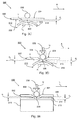
- Fig. 3C shows a first stage of a method of operating the cleaning assembly shown in Fig. 3A .
- Fig. 3C is a detail E shown in Fig. 3A .
- the predetermined distance may be about 1 mm or may be less than 1 mm.
- the cleaning layer 214 is moved by the cleaning roller 210 in a circular direction as indicated by arrow R 1 , thereby moving the cleaning layer 214 in a direction T along the contact area 226 of the the mixing blade 220.
- the first surface 222 does not contact the cleaning layer 214.
- Fig. 3D shows a second stage of a method of operating the cleaning assembly shown in Fig. 3A .
- Fig. 3E shows the second stage of the cleaning assembly shown in Fig. 3D along the contact area 226.
- the pressure element 232 is urged against the second surface 224 of the mixing blade, thereby deforming the mixing blade 220 at a first position 236 along the contact area 226.
- a first contact portion 233 is urged against the cleaning layer 214.
- the cleaning layer 214 has a thickness as indicated by d 2 .
- the cleaning layer 214 is mixed due to the movement of the cleaning layer 214 in a direction T.
- the speed of the movement in direction T is suitably selected in order to control the mixing behavior.
- the mixing behavior can be further enhanced by suitably controlling a thickness of the cleaning layer 214 between the first contact portion 233 of the mixing blade 220 and the cleaning surface 212.
- the thickness may be reduced well below the initial thickness d 2 .
- a dimension of the first contact portion 233 (e.g. a length in the direction A and / or a length in the direction L) may be suitably adapted by selecting a shape of the pressure element 232, selecting a shape and / or material type of mixing blade 220 and / or selecting a pressure force as indicated by U adapted for urging the mixing blade at the first position 236 towards the cleaning layer 214.
- the shape of the pressure element 232 may be a roller, may be a ball, may be a cam element and may be any other shape.
- a person skilled in the art may easily contemplate which shape of the pressure element 232 is suitable for providing a desired dimension of the first contact portion 233.
- the shape of the pressure element 232 is a ball, which provides a spherical contact to the second surface 224 of the mixing blade.
- the mixing blade 220 provides a uniform resistance to the pressure applied by the pressure element 232 to the second surface 224.
- the first contact portion 233 has a substantially round shape (as schematically shown in Fig.
- the pressure element 232 may in an alternative embodiment be a roller, which roller is arranged having a round perimeter in contact with the second surface 224.
- the pressure element 232 may be a cam element, which cam element is rotatably mounted on an axis (for example as shown in the embodiment shown in Figs. 7A-7B ).
- the cleaning roller 210 may in an embodiment comprise a plurality of grooves.
- the cleaning surface 212 of the cleaning roller may comprise a number of spirally arranged grooves.
- Each of the grooves is adapted for transporting the cleaning layer from the cleaning surface 212 into the cleaning roller 210.
- the groove is a V-shaped groove having a width of about 4 mm and a depth of about 4 mm. Between adjacent grooves a dam present at the cleaning surface may have a width of about 0,1 mm - 1 mm. It is known for a person skilled in the art how to suitably adapt a groove for the purpose of transporting the cleaning layer from the cleaning surface 212 into the cleaning roller 210, based on a process for replacing the cleaning layer.
- Fig. 4A shows a first stage of an embodiment of a method of operating the cleaning assembly according to the invention.
- Fig. 4B shows a second stage of the embodiment of the method of operating the cleaning assembly shown in Fig. 4A.
- Figs. 4A and 4B shows a detail E of the cleaning assembly as shown in Fig. 3A .
- the pressure unit 330 comprises a first pressure element 332a and a second pressure element 332b. Each of the pressure elements 332a, 332b is arranged adjacent to the second surface 224 of the mixing blade 220.
- the first pressure element 332a is adapted for deforming the mixing blade 220 at a first position 336a and the second pressure element 332b is adapted for deforming the mixing blade 220 at a second position 336b.
- the mixing blade 220 is arranged at a distance d 1 from the cleaning layer 214 along the contact area 226.
- the first pressure element 332a is urged against the second surface 224 as indicated by arrow U and consequently deforms the mixing blade 220 at the first position 336a.
- the first contact portion 333a along the contact area 226 is urged against the cleaning layer 214, thereby contacting the cleaning layer 214.
- the second pressure element 332b does not deform the mixing blade 220.
- the second pressure element 332b deforms the mixing blade at the second position 336b.
- the second contact portion 333b of the first surface 222 along the contact area 226 in the contact line direction C is urged against the cleaning layer 214 as indicated by arrow U, thereby contacting the cleaning layer 214.
- the first pressure element 332a does not deform the mixing blade 220.
- the second contact portion 333b has a partial overlap with the first contact portion 333a along the contact area 226 as indicated in Fig. 4B .
- the cleaning layer 214 is mixed in the corresponding part 333a, 333b of the contact area 226.
- both the first pressure element 332a and the second pressure element 332b are urged against the second surface 224 at the same time, thereby deforming the mixing blade 220 both at the first position 336a and the second position 336b simultaneously.
- the corresponding first contact portion 333a and second contact portion 333b are urged against the cleaning layer 214 at the same time.
- Fig. 5 shows an embodiment of the cleaning assembly according to the invention.
- Fig. 5 is a detail E of the cleaning assembly as shown in Fig. 3A .
- a plurality of pressure elements 532a, 532b, 532c, 532d is provided adjacent to the second surface 224 in an array in the contact line direction C along the contact area 226 for moving a respective contact portion 533a, 533b, 533c, 533d in contact with the cleaning layer 214.
- the mixing blade 220 is arranged at a distance d 1 from the cleaning layer 214 along the contact area 226. In the stage shown in Fig.
- one of the pressure elements 532b is urged against the second surface 224 as indicated by arrow U at a second position 536b.
- the corresponding contact portion 533b is urged against the cleaning layer 214, which cleaning layer 214 is present on the cleaning surface 212 of the cleaning member 210.
- each of the other pressure elements 532a, 532c, 532d is urged against the second surface 224 at the corresponding position for deforming the mixing blade 220.
- one or more of the pressure elements 533a, 533b, 533c, 533d may be urged against the second surface 224 simultaneously for moving the corresponding contact portions in contact with the cleaning layer 214.
- Each of the contact portions 533a, 533b, 533c, 533d have a partial overlap with an adjacent contact portion in the contact line direction C along the contact area 226.
- Figs. 6A and 6B show an embodiment of the mixing blade of the cleaning assembly according to the invention.
- Fig. 6A shows a plane view of the mixing blade 220 at the first surface 222.
- Fig. 6B shows a side view of the mixing blade of Fig. 6A along the first direction A.
- the mixing blade 220 has a rectangular shape extending in a first direction as indicated by arrow A and a lateral direction as indicated by arrow L.
- a contact area 226 extends in the contact line direction C substantially parallel to the lateral direction L and is arranged in between a first end 220a and a second end 220b in the first direction A.
- Fig. 6A shows a plane view of the mixing blade 220 at the first surface 222.
- Fig. 6B shows a side view of the mixing blade of Fig. 6A along the first direction A.
- the mixing blade 220 has a rectangular shape extending in a first direction as indicated by arrow A and a lateral direction as indicated by
- the mixing blade 220 is supported at the first end 220a by a plurality of supporting elements 229 and is freely movably arranged at the second end 220b in a height direction as indicated by arrow H.
- a number of heating elements 250 are mounted on the second surface 224 of the mixing blade 220 and are arranged adjacent to the contact area 226 in the first direction A.
- the heater elements 250 are controlled by control unit 100 and are adapted for controlling the temperature of the contact area 226.
- the mixing blade 220 further comprises a hinge portion 240, which is arranged between the contact area 226 and the first end 220a in the first direction A.
- the hinge portion comprises a plurality of hinge lips 242a, 242b, distributed along the contact line direction C.
- Each of the hinge lips 242a, 242b extend in the first direction A and are confined at each side of the corresponding hinge lip 242a, 242b by a recess 244 in the contact line direction C.
- the recesses 244 arranged at both sides of the hinge lip 242a, 242b define a width of the hinge lip 242a, 242b in the contact line direction C.
- the recess 244 extends both in the contact line direction C and in the first direction A over a distance in the range of 10 mm - 25 mm.
- the recess 244 has a substantially rectangular shape.
- the width of the hinge lip 242a, 242b in the lateral direction is about 1 mm.
- the hinge portion 240 further comprises an edge hinge segment 242c arranged at each end in the contact line direction C.
- the edge hinge segment is confined by the edge of the mixing blade 220 at one side and by a recess 244 at the other side in the contact line direction C.
- the edge hinge segment 242c has a width in the contact line direction C, which is substantially larger than the width of the hinge lips 242a, 242b. In an example the width of the edge hinge segments 242c is in the range of 4 mm - 12 mm.
- the edge hinge segment is adapted for providing sufficient stiffness to the contact area 226 near the edge of the mixing blade in the contact line direction C.
- the hinge portion 240 further comprises an intermediate hinge segment 242d.
- the intermediate hinge segment 242d is arranged in a middle position 636x between a first position 636a and a second position 636b as indicated by arrow L and arrow -L along the contact area 226 at an equal distance from both the first position 636a and the second position 636b.
- the mixing blade 220 is deformed by a pressure element (not shown) at the first position 636a and is deformed at the second position 636b at the same time.
- the intermediate hinge segment 242d has a width in the contact line direction C, which is larger than the width of the hinge lips 242a, 242b in the contact line direction C.
- the width of the intermediate hinge segment 242d is in the range of 10 mm - 25 mm.
- the intermediate hinge segment 242d is adapted for providing sufficient stiffness to the contact area 226 at the middle position 636x such that the contact area 226 is substantially not deformed at the middle position 636x by the deformations occuring at the first position 636a and the second position 636a.
- Figs. 7A and 7B show an embodiment of the pressure unit of the cleaning assembly shown according to the invention.
- the pressure unit 730 shown comprises a rotatable axis 731 and a plurality of cam elements 732a, 732b, 732c, 732d.
- the rotatable axis 731 extends in a contact line direction C along a contact area 226 of the mixing blade 220.
- the rotatable axis 731 is rotatable as indicated by arrow R c .
- Each of the plurality of cam elements 732a, 732b, 732c, 732d is connected to the axis 731 and is distributed along the contact area 226.
- Fig. 7A the pressure unit 730 shown comprises a rotatable axis 731 and a plurality of cam elements 732a, 732b, 732c, 732d.
- cam elements 732b, 732d are urged against the second surface 224 of the mixing blade 220 as indicated by arrow U at a respective position 736b, 736d.
- the cam elements 732a, 732b, 732c, 732d are urged against the second surface 224 by means of a force communicated by the rotatable axis 731 on the cam elements 732a, 732b, 732c, 732d.
- the mixing blade 220 is arranged at a predetermined distance d 1 from the cleaning layer 214 along the contact area 226. In the first stage two other cam elements 732a, 732c are projecting away from the second surface 224.
- Each of the cam elements 732a, 732b, 732c, 732d moves a corresponding contact portion 733a, 733b, 733c, 733d of the mixing blade in contact with the cleaning layer 214.
- the contact portions 733a, 733b, 733c, 733d have a partial overlap with each of the adjacent contact portions in the contact line direction C.
- fig. 7B is shown a side view of the pressure unit 730 in the first direction A perpendicular to the contact area 226.
- a first cam element 732a and a second cam element 732b is shown.
- the first cam element 732a is oriented opposite to the second cam element 732b perpendicular to the axis of rotation, which is indicated by arrow R c .
- the second cam element 732 is urged against the second surface 224, thereby deforming the mixing blade 220 at the second position 736b.
- Each of the cam elements 732a, 732b have a tapered outer edge 734a, 734b, which may be arranged in urging contact with the second surface 224 of the mixing blade.
- each of the cam elements 732a, 732b has a curved edge part 735a, 735b, which is adjoined to the outer edge 734a, 734b at ine end and is bended towards the rotatable axis 731 at another end.
- the first cam element 732a is urged against the second surface 224 at a corresponding first position (not shown), thereby moving a first contact portion 733a in contact with the cleaning layer 214 and moving the second cam element 732b away from the second surface 224.
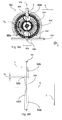
- Figs. 8A and 8B show an embodiment of the pressure unit of the cleaning assembly shown according to the invention.
- Fig. 8A shows a view of the pressure unit 830 and a mixing blade 220 along a first direction A and perpendicular to the contact area 226 extending in the contact line direction C.
- Fig. 8B shows a partial view of the pressure unit 830 along the contact line direction C.
- the pressure unit 830 comprises a shaft 831, a plurality of pressure elements 832a, 832b, a bearing cage 834 and a socket 835.
- the mixing blade 220 and the socket 835 are not shown.
- the shaft 831 extends in the contact line direction C and is arranged near the second surface 224 of the mixing blade 220 adjacent to the contact area 226.
- the plurality of pressure elements 832a, 832b are balls, which are distributed in an assembly around the shaft 831 along the contact line direction C as is shown in Fig. 8B .
- Each of the balls 832a, 832b is arranged adjacent to the shaft 831 and is adapted for a circular movement around the shaft 831 in the direction as indicated by arrow R b perpendicular to the contact line direction C.
- the bearing cage 834 is arranged around the shaft 831 and is adapted for holding each of the balls 832a, 832b in the assembly at a constant position with respect to another ball 832a, 832b of the assembly.
- the assembly of balls 832a, 832b is rotated around the shaft 831 by rotational movement of the bearing cage 834 around the shaft 831 in the direction R b .
- the socket 835 and the mixing blade 220 in cooperation enclose the assembly of balls 832a, 832b.
- at least one of the balls 832a, 832b is urged in contact with the second surface 224 of the mixing blade 220.
- the mixing blade 220 is locally deformed at a position 836 along the contact area 226 and a corresponding contact portion is urged against a cleaning layer of a cleaning member (not shown).
- a first ball 832a of the plurality of balls 832a, 832b is arranged substantially opposite to a second ball 832b with respect to the shaft 831 as schematically indicated for one pair of balls 832a, 832b by line 842.
- the socket 835 is adapted for providing an urging force to the first ball 832a as indicated by arrow U, which urging force is further transmitted to the second ball 832b via the shaft 831.
- the second ball 832b contacts and by urging force U deforms the second surface 224 at the position 836.
- the first ball 832a is arranged offset in the direction C from the second ball 832b over substantially half a distance d b between adjacent second balls 832b in the contact line direction C.
- a corresponding first contact portion 836 of a first ball 832a is arranged between two contact portions 836 of two adjacent second balls 832b in the contact line direction C having a partial overlap with each contact portion 836 of said two adjacent second balls 832b.
- plurality is defined as two or more than two.
- another is defined as at least a second or more.
- the terms including and/or having, as used herein, are defined as comprising (i.e., open language).
- coupled is defined as connected, although not necessarily directly.
Landscapes
- Physics & Mathematics (AREA)
- General Physics & Mathematics (AREA)
- Electrostatic Charge, Transfer And Separation In Electrography (AREA)
Abstract
Description
- The present invention relates to a cleaning assembly. The present invention further relates to a method for operating the cleaning assembly according to the present invention. The present invention further relates to an apparatus comprising the cleaning assembly according to the present invention.
- In a known cleaning assembly of a toner printing apparatus a cleaning roller is provided comprising an outer cleaning surface carrying a cleaning layer, which cleaning layer in operation is a tacky layer. The cleaning roller comprises a cavity and the cleaning surface comprises a plurality of grooves arranged in fluid connection to the cavity and being adapted for discharging an excess portion of cleaning layer into the cleaning roller. The printing apparatus further comprises a toner imaging station and an intermediate imaging member. The intermediate imaging member is adapted for in a first transfer nip receiving the image from the imaging station and in a second transfer nip transferring the image to the receiving substrate.
- In the second transfer nip contaminations from the receiving substrate, such as paper dust, may be transferred onto the intermediate imaging member. In operation of the cleaning assembly, the tacky cleaning layer of the cleaning roller is arranged in contact with the intermediate imaging member, in order to remove the contaminations from the intermediate imaging member. However in time these contaminations, such as paper dust, saturate the outer surface of the cleaning layer. As a result the tackiness of the cleaning layer may diminish and the cleaning layer may lose its cleaning function.
- In order to maintain the tackiness of the cleaning layer the material of the cleaning layer is supplemented, for example by frequently supplying toner material to the cleaning layer to be used as tacky cleaning material. A disadvantage of the frequent supply of toner to the cleaning roller is that more toner is used as cleaning material instead of for printing toner images on receiving substrates. Furthermore the frequent supply of toner material may also lower the production speed of the printing apparatus.
- It is accordingly an object of the present invention to provide a method for maintaining a cleaning function of a cleaning layer on a cleaning member while reducing the consumption of cleaning material of the cleaning layer.
- This object is attained by a cleaning assembly, the cleaning assembly comprising:
- a mixing blade having a first surface and a second surface arranged opposite to the first surface;
- a cleaning member comprising a cleaning surface carrying a cleaning layer, the cleaning member being adapted for in mixing operation moving the cleaning layer in a transport direction along the first surface of the mixing blade; wherein a contact area of the first surface of the mixing blade is arranged facing the cleaning layer; and a pressure unit comprising a first pressure element being movably arranged adjacent to the second surface of the mixing blade, the pressure element being adapted for in mixing operation deforming the mixing blade at a first position, thereby moving a first contact portion of the contact area in contact with the cleaning layer.
- The cleaning assembly of the present invention maintains a cleaning function of the cleaning layer by locally mixing the cleaning layer due to the contact of the first contact portion of the contact area of the mixing blade with the cleaning layer while the cleaning layer is moved in the transport direction along the first surface of the mixing blade. The cleaning layer is locally mixed due to a shear processes in the transport direction, which shear processes are provided inside the cleaning layer while being in contact with the first contact portion. By mixing the cleaning layer any contaminations, which are present on top of the cleaning layer, are mixed into the cleaning layer. As a result the tackiness of the cleaning layer is maintained at an appropriate level.
- The contact area of the first surface is in mixing operation arranged facing the cleaning layer while not contacting the cleaning layer. The contact area of the first surface of the mixing blade may be arranged facing the cleaning layer at a predetermined distance from the cleaning layer. For example the predetermined distance may be smaller than 2 mm, preferably smaller than 1 mm. The predetermined distance is selected such that in a standby state of the cleaning member, wherein the cleaning layer is held stationary with respect to the mixing blade, no contact is provided between the cleaning layer and the mixing blade. This arrangement prevents transfer of cleaning material from the cleaning layer to the first surface of the mixing blade in the standby state.
The distance between the contact area of the mixing blade and the cleaning layer may be substantially constant along the contact area.
The first surface of the mixing blade may be a first side, and the second surface of the mixing blade may be a second side, opposite to the first side. The mixing blade may comprise a metal sheet, for example a resilient metal sheet. The mixing blade may comprise a thermal conductive material. For example the thermal conductive material may have a thermal conductivity coefficient of at least 10 W / m.K. The mixing blade may have a heat capacity material adapted providing a heat capacity. For example the heat capacity material may have a specific heat capacity coefficient of at least 0,4 J / kg.K.
The mixing blade may have a substantially rectangular shape, and may have a substantially straight edge arranged at a first end of the mixing blade and / or may have a substantially straight edge arranged at a second end of the mixing blade. The mixing blade may have a substantially flat first surface and may have a substantially flat second surface. In particular the first surface along the contact area may be substantially flat. - The cleaning member is adapted for in mixing operation moving the cleaning layer in a transport direction along the contact area of the first surface of the mixing blade. The cleaning member may be a cleaning roller (e.g. a cylinder) carrying said cleaning layer on the cylindrical surface, and the cleaning member may comprise an endless cleaning belt carrying said cleaning layer. The cleaning member may be moved by a driving mechanism. For example a driving mechanism may rotate a cleaning roller by driving an axis of the cleaning roller in a rotational direction.
In particular in mixing operation of the cleaning assembly the cleaning layer is moved in the transport direction along the contact area while a first contact portion of the mixing blade is moved in contact with the cleaning layer. The moving cleaning layer is mixed in the area of contact with the first contact portion of the mixing blade. The cleaning layer may be partially compressed during passing along the first contact portion of the mixing blade. A contamination, which is present on top of the cleaning layer, is mixed into the cleaning layer by the first portion of the mixing blade.
The cleaning layer may have a thickness of less than 1 mm, for example a thickness less than 100 micron. The cleaning layer may comprise any kind of tacky material, including may comprise a toner material, and may comprise a polymeric material. The cleaning layer may be heated to any temperature higher than room temperature which temperature is suitable to render the material in a tacky state, for example to a temperature of at least 100°C.
The contact area may extend in a contact line direction, for example may extend in the contact line direction along a width of the cleaning layer. In an embodiment, the contact line direction of the contact area is substantially parallel to a lateral direction of the mixing blade. - The first pressure element is movably arranged such that in mixing operation the first pressure element moves a first contact portion of the contact area in contact with the cleaning layer. In mixing operation the first pressure element is urged against the second surface of the mixing blade at the first position.
The mixing blade is an elastically deformable sheet. Thus the mixing blade returns to an initial shape and position in case the first pressure element is not urged against the second surface.
The mixing blade may be a thin sheet, wherein the second surface is arranged close to the first surface. For example the mixing blade may have a thickness of smaller than 2 mm, more preferably smaller than 1 mm. A pressure for deforming the mixing blade by the pressure element may be suitably selected.
The first position on the second surface may be arranged opposite to the first contact portion on the first surface.
In an alternative embodiment the first position on the second surface may be arranged away from the first contact portion on the first surface.
In a particular embodiment the mixing blade may comprise a lever portion, which lever portion extends from the first position to the first contact portion. The lever portion may for example be confined by two grooves which are arranged in the second surface, both grooves extending in a direction from the first position to the first mixing position and each of the grooves being arranged at one side of the lever portion opposite to each other. The grooves enhance confinement of the deformation of the mixing blade within the lever portion. Said deformation being provided in response to the first pressure element urging on the mixing blade in the first position. The lever portion further provides the advantage that the first position may be arranged away from the first contact portion.
Attributes of the pressure element may be adapted for locally deforming the mixing blade at the first position on the second surface and the first contact portion on the first surface. A shape of the pressure element may be suitably selected for locally deforming the mixing blade. For example the pressure element may have a convex contact surface, for example a spherical contact surface, which is arranged in contact with the second surface of the mixing blade in the first position. The pressure element may comprise a ball, may comprise a roller element, may comprise a cam element, may comprise a finger element and may comprise any other suitable element for deforming the mixing blade at the first position.
The first contact portion may have a width (i.e. perpendicular to the contact line direction), which corresponds to a width of the contact area perpendicular to the contact line direction. The first contact portion may extend over a whole length of the contact area in the contact line direction. The advantage is that the cleaning layer may be mixed at once over the length of the contact area in the contact line direction.
Alternatively the first contact portion may extend over a part of the length of the contact area in the contact line direction. The advantage is that the cleaning layer is selectively mixed by the first contact portion at a desired position over a part of the length in the contact line direction.
In any way the first contact portion may be suitably selected by a person skilled in the art based on desired mixing time for the cleaning layer and / or desired forces acting on the mixing blade. - The cleaning assembly according to the invention may be used to clean any kind of surface, for instance may be used to clean an imaging surface or an intermediate imaging surface of a printing apparatus, for example in particular a toner printing apparatus. In an embodiment the cleaning assembly may be adapted for cleaning an imaging surface or an intermediate imaging surface by arranging the cleaning layer in contact with said surface away from the mixing blade. For example the cleaning layer may be arranged in rolling contact with said surface. By moving the cleaning layer on the cleaning member, the cleaning layer is moved from said cleaning area for cleaning the surface to said contact area of the mixing blade for mixing the cleaning layer according to the present invention and vice versa.
- In an embodiment of the cleaning assembly, the cleaning assembly further comprises a heating means adapted for heating the mixing blade, such that a temperature of the contact area of the mixing blade is higher than a temperature of the cleaning layer. The advantage is that a higher temperature of the contact area improves the mixing effectivity of the first contact portion on the cleaning layer (e.g. improving the shear process inside the cleaning layer. As a result a shorter mixing time may be sufficient and / or the level of mixing of the cleaning layer is improved. Another advantage of the higher temperature of the contact area is that a contamination of the mixing blade by the cleaning layer is prevented, by prohibiting or at least minimizing transfer of a portion of the cleaning layer to the mixing blade.
For example said temperature of the contact area is at least 10°C higher than the temperature of the cleaning layer. In another example said temperature of the contact area is in the range of 150°C - 220°C, more preferably the temperature of the contact area is in the range of 180°C - 220°C.
The heating means may be mounted on the first surface and may be mounted on the second surface of the mixing blade. The heating means may be arranged adjacent to the contact area. In particular the heating means may be arranged adjacent to the first contact portion of the mixing blade. The heating means may comprise a temperature detector for detecting the temperature of the mixing blade. In an example the temperature detector detects the temperature within 10 mm distance of the contact area. Said temperature detector may comprise a thermo-couple element. - In an embodiment of the cleaning assembly, the contact area extends in a contact line direction and the first contact portion extends over a part of the contact area in the contact line direction. Said part of the contact area may be a minor portion of the contact area in the contact line direction. When the first contact portion is moved in contact with the cleaning layer, the contact pressure and the friction of the cleaning layer to the mixing blade may provide a pulling force on the mixing blade in the transport direction of the cleaning layer. The advantage the embodiment is that the pulling forces on the mixing blade are controlled by suitably adjusting the size of the first contact portion in the contact line direction. For example a ball shaped pressure element may provide a first contact portion in the contact line direction which is a minor portion of the contact area compared to a rod shaped pressure element providing a contact portion extending over the contact area in the contact line direction. The transport direction of the cleaning layer may be arranged substantially perpendicular to the contact area extending in the contact line direction.
In an example a length of the first contact portion in the contact line direction is at most 30 mm, in a particular example the length of the first contact portion in the contact line direction is at most 20 mm, more preferably the length of the first contact portion in the contact line direction is about 10 mm. In an embodiment the pressure unit may comprise a plurality of pressure elements, each of the plurality of pressure elements having a functionality as the first pressure element, wherein each pressure element is adapted for deforming a contact portion of the contact area in the contact line direction, and wherein the plurality of respective first and following contact portions is adapted for extending over the contact area. As such the cleaning layer may be mixed over the contact area, wherein in embodiments the contact portions are provided by the plurality of pressure elements either simultaneously or subsequently. - In an embodiment the pressure unit further comprises a second pressure element, which is movably arranged adjacent to the second surface of the mixing blade, wherein the second pressure element is adapted for deforming the mixing blade at a second position, thereby moving a second contact portion of the contact area in contact with the cleaning layer. In this embodiment the first contact portion may be provided independently of providing the second contact portion. For example said first contact portion may be provided adjacent to said second contact portion in the contact line direction. Said second pressure element may be adapted for in mixing operation deforming the mixing blade at the second position simultaneously with the first pressure element deforming the mixing blade at the first position. Said embodiment shortens the time for mixing the cleaning layer.
Alternatively said second pressure element may be adapted for in mixing operation deforming the mixing blade at the second position at a different time of the first pressure element deforming the mixing blade at the first position. In each of the particular embodiments the shear forces acting on the mixing blade due to the mixing operation of the respective first contact portion and the second contact portion may be suitably balanced. For example in each of the particular embodiments the relative position of the first and second contact portions with respect to each other may be suitably selected. - In an embodiment of the cleaning assembly, the mixing blade extends in a first direction and wherein the cleaning assembly further comprises a number of supporting elements, wherein the mixing blade is supported by the number of supporting elements at a first end of the mixing blade in the first direction. The number of supporting elements is adapted for maintaining the contact area stationary with respect to the first direction. The number of supporting elements provides a controlled position of the contact area with respect to the cleaning layer independent of the movement of the cleaning layer with respect to the first direction. As such the number of supporting elements supports the mixing (i.e. shear process) of the cleaning layer.
- In an embodiment of the cleaning assembly, the mixing blade is freely movably arranged in a direction perpendicular to the first surface at a second end of the mixing blade, which second end is arranged opposite to the first end in the first direction. The embodiment supports a simple construction of the mixing blade.
- In an embodiment of the cleaning assembly, the mixing blade comprises a hinge portion being arranged between the contact area and the first end in the first direction, said hinge portion comprising a plurality of hinge segments distributed along the contact line direction. The advantage of said hinge portion is that a position, a size and a pressure of each contact portion along the contact area in the contact line direction may be suitably controlled. In particular the attributes of each contact portion along the contact area in the contact line direction may be adapted by adapting the plurality of hinge segments along the contact line direction.
- In an embodiment of the cleaning assembly, at least one of the hinge segments is a hinge lip extending substantially in the first direction, wherein the hinge lip is confined at each side of the hinge lip in the contact line direction by a recess. A width of the hinge lip in the contact line direction is defined by the recesses, wherein the recesses confine the hinge lip in the contact line direction. The advantage of said hinge lips is that the selection of attributes of the hinge element (e.g. size, material) is simple, based on an intended control on each of the number of contact portions along the contact area in the contact line direction.
- In an embodiment of the cleaning assembly, at least one of the hinge segments is an edge hinge segment, which edge hinge segment is arranged at an edge of the mixing blade in the contact line direction, the edge hinge segment having a width adapted to be larger than a width of the hinge lip in the contact line direction. The advantage is that a contact portion, provided by a pressure element, which is arranged adjacent to said edge, is substantially the same as another contact portion, provided by the same pressure element and arranged away from said edge. This simplifies the construction of the pressure unit and / or the mixing blade.
- In another aspect of the invention a method is provided for operating a cleaning assembly, which cleaning assembly comprises: a cleaning member comprising a cleaning surface carrying a cleaning layer; a mixing blade having a first surface and a second surface arranged opposite to the first surface; and a pressure unit comprising a first pressure element being movably arranged adjacent to the second surface of the mixing blade; the method comprising the steps of:
- a)arranging a contact area of the first surface of the mixing blade facing the cleaning layer;
- b) moving the cleaning member such that the cleaning layer is moved in a transport direction along the contact area of the mixing blade; and
- c) urging the first pressure element against the second surface of the mixing blade, thereby deforming the mixing blade at a first position and moving a first contact portion of the contact area in contact with the cleaning layer.
- The arranging step provides that the contact area of the mixing blade is arranged in a suitable position with respect to the cleaning layer. In particular in the arranging step the contact area is arranged not in contact with the cleaning layer. The moving step of the cleaning layer provides that the cleaning layer may be adapted for a suitable movement with respect to the contact area in a mixing process of the cleaning layer during the urging step. The urging step provides that a suitable first contact portion of the contact area of the mixing blade is placed in contact with the cleaning layer.
The cleaning layer may become locally and / or temporarily thinner in response to the contact of the first contact portion. The cleaning layer is mixed by the first contact portion due to a shearing deformation of the moving cleaning layer with respect to the first contact portion. The moving step and the urging step are performed at the same time. - In the arranging step the contact area may be arranged at a predetermined distance from the cleaning layer. The contact area may be arranged at a substantially constant distance from the cleaning layer at each position of the contact area (for example at each position along a contact line direction, wherein the contact area may extend in the contact line direction).
In the moving step the cleaning layer may be moved at a substantially constant velocity in the transport direction. In an embodiment, the mixing blade may extend in a first direction and wherein in the moving step the transport direction is substantially parallel to the first direction of the mixing blade. In an embodiment, the moving step comprises moving the cleaning member in a cyclic movement, thereby moving the cleaning layer along the contact area of the mixing blade in the transport direction. In an embodiment, the method comprises moving each part of a cyclic line of the cleaning layer at least two times along the first contact portion while performing the urging step.
In the urging step the urging force of the pressure element against the second surface is preferably in the range of 5N - 20N. The urging force may be suitably selected for deforming the mixing blade and moving the first contact portion in contact with the cleaning layer.
In the urging step the first contact portion may be a minor portion of the contact area. In the urging the step the first contact portion may be suitably selected based on a desired shear force acting on the mixing blade. In the urging step the pressure element may be urged in a direction substantially perpendicular to the second surface. In an embodiment the urging step may comprise moving the pressure element along the second surface. For example a rolling element (i.e. the pressure element) may be moved in rolling contact with the second surface while being urged at the first position in order to deform the mixing blade. The rolling element may be a roller, may be a ball, may be a cam element and may have any other suitable shape for a rolling contact. - In an embodiment, the method further comprises heating the mixing blade such that a temperature of the first contact portion of the mixing blade is higher than a temperature of the cleaning layer. The heating step improves the mixing process and reduces transfer of material of the cleaning layer to mixing blade.
- In an embodiment, the contact area extends in a contact line direction and the pressure element is movably arranged in the contact line direction along the second surface of the mixing blade.
In an embodiment, the urging step comprises moving the first pressure element in the contact line direction in a rolling contact along the second surface of the mixing blade while urging the first pressure element against the second surface of the mixing blade, thereby moving a corresponding portion of the first surface of the mixing blade along the contact area in the contact line direction in contact with the cleaning layer. In this embodiment the rolling contact of the first pressure element along the second surface of the mixing blade provides a simple way of providing a contact portion moving along the contact area in the contact line direction. - In an embodiment of the method, the pressure unit further comprises a second pressure element and the method further comprises a second urging step, which comprises urging the second pressure element against the second surface of the mixing blade, thereby deforming the mixing blade at a second position and moving a corresponding second contact portion of the contact area in contact with the cleaning layer. The second urging step provides a second contact portion independent of the first contact portion of said (first) urging step.
- In an embodiment of the method, the first contact portion of the urging step has a partial overlap with the second contact portion of the second urging step. The partial overlap improves a mixing process of the cleaning layer along the contact area.
- In an embodiment of the method, the urging step and the second urging step are carried out subsequently. This embodiment may enable a balanced load on the mixing blade and/or on the cleaning layer.
- In an embodiment of the method, the urging step and the second urging step are carried out substantially at the same time. This embodiment may increase an efficiency of mixing the cleaning layer.
- In another aspect of the invention a printing apparatus is provided for providing an image on a receiving substrate, comprising: an imaging station for forming the image; an intermediate imaging member adapted for in a first transfer nip receiving the image from the imaging station and in a second transfer nip transferring the image to the receiving substrate; and a cleaning assembly according to the invention configured for removing a contamination from the intermediate imaging member, wherein the cleaning layer comprises a tacky material and wherein the cleaning layer in operation is urged in contact with the intermediate imaging member. The cleaning assembly according to the invention enhances the printing productivity of the apparatus as the mixing of the cleaning layer increases the durability of the cleaning layer. Little replacement of tacky cleaning material may be necessary for effectively using the cleaning layer.
- In an embodiment, the mixing blade comprises a material selected from the group of spring steel and aluminum. Spring steel and aluminum are both suitable materials due to their intrinsic heat capacity, heat conductivity and elastic deformability. More preferably spring steel is used.
- In an embodiment, at least one of the hinge segments is an intermediate hinge segment, wherein the intermediate hinge segment has a width adapted to be larger than the width of the hinge lip in the contact line direction. The intermediate hinge segment provides increased stiffness to the contact area at a middle position. As such an intermediate hinge segment is suitable for supporting a middle position and accordingly enhancing an independent deformation at a first position and a second position occurring at the same time.
- In an embodiment, the pressure unit further comprises a shaft extending substantially in the contact line direction, wherein the shaft is adapted for applying a pressure to the first pressure element and the second pressure element, thereby deforming the mixing blade at the corresponding first position and second position along the contact area. The shaft supports a simple construction of the pressure unit.
- In an embodiment, the pressure unit comprises a plurality of pressure elements and comprises a shaft extending substantially in the contact line direction, wherein said plurality of pressure elements is distributed in an assembly around the shaft along the contact line direction and wherein each of the plurality of pressure elements is adapted for a circular movement around the shaft substantially perpendicular to the contact line direction, wherein in a portion of said circular movement of a pressure element a corresponding contact portion of the first surface of the mixing blade along the contact area is moved in contact with the cleaning layer at the respective position of the mixing blade in the contact line direction. The embodiment provides a compact construction of a pressure unit adapted for operating a plurality of pressure elements.
- In an embodiment, each of the plurality of pressure elements is in the form of a cam element being fixed to the shaft. The embodiment provides a simple construction of the assembly of plurality of pressure elements.
- In an embodiment, each of the plurality of pressure elements is in the form of a roller bearing and the pressure unit further comprises a roller bearing cage, wherein the roller bearing cage is arranged around the shaft and is adapted for retaining each of the roller bearings in the assembly at a fixed position with respect to the other roller bearings. The roller bearings may enhance the durability of the cleaning assembly by providing a rolling contact between the pressure element and the second surface of the mixing blade.
- In an embodiment, each of the plurality of pressure elements is in the form of a ball and the pressure unit further comprises a ball bearing cage and a socket, wherein the ball bearing cage is arranged around the shaft and is adapted for retaining each of the ball bearings in the assembly in a fixed position with respect to the other ball bearings, and wherein the socket and the mixing blade cooperatively enclose the assembly of the ball bearings. This embodiment provides a simple rolling element bearing construction.
- In an embodiment, the cleaning member comprises a cavity and the cleaning surface comprises a plurality of grooves arranged in fluid connection to the cavity and being adapted for discharging an excess portion of cleaning layer into the cleaning member. The cleaning member provides a simple construction for enhancing a replacement of a cleaning layer.
- In an embodiment, the cleaning layer comprises a tacky material. In a particular embodiment, the tacky material comprises a toner resin. The toner material is a suitable material for a cleaning layer and is preferably heated to a temperature higher than room temperature.
- Thus the present invention pertains to a cleaning assembly, the cleaning assembly comprising:
- a mixing blade having a first surface and a second surface arranged opposite to the first surface;
- a cleaning member comprising a cleaning surface carrying a cleaning layer, the cleaning member being adapted for in mixing operation moving the cleaning layer in a transport direction along the first surface of the mixing blade; wherein a contact area of the first surface of the mixing blade is arranged facing the cleaning layer; and a pressure unit comprising a first pressure element being movably arranged adjacent to the second surface of the mixing blade, the pressure element being adapted for in mixing operation deforming the mixing blade at a first position, thereby moving a first contact portion of the contact area in contact with the cleaning layer for locally mixing the cleaner layer while the cleaning layer is moved in the transport direction along the first surface of the mixing blade.
- The cleaning assembly of the present invention maintains a cleaning function of the cleaning layer by locally mixing the cleaning layer due to the contact of the first contact portion of the contact area of the mixing blade with the cleaning layer while the cleaning layer is moved in the transport direction along the first surface of the mixing blade. The cleaning layer is locally mixed due to a shear processes in the transport direction, which shear processes are provided inside the cleaning layer while being in contact with the first contact portion. By mixing the cleaning layer any contaminations, which are present on top of the cleaning layer, are mixed into the cleaning layer. As a result the tackiness of the cleaning layer is maintained at an appropriate level.
- In another aspect of the invention a method is provided for operating a cleaning assembly, which cleaning assembly comprises: a cleaning member comprising a cleaning surface carrying a cleaning layer; a mixing blade having a first surface and a second surface arranged opposite to the first surface; and a pressure unit comprising a first pressure element being movably arranged adjacent to the second surface of the mixing blade; the method comprising the steps of:
- a)arranging a contact area of the first surface of the mixing blade facing the cleaning layer;
- b) moving the cleaning member such that the cleaning layer is moved in a transport direction along the contact area of the mixing blade; and
- c) urging the first pressure element against the second surface of the mixing blade, thereby deforming the mixing blade at a first position and moving a first contact portion of the contact area in contact with the cleaning layer for locally mixing the cleaner layer; wherein step c) is performed during step b).
- The arranging step provides that the contact area of the mixing blade is arranged in a suitable position with respect to the cleaning layer. In particular in the arranging step the contact area is arranged not in contact with the cleaning layer. The moving step of the cleaning layer provides that the cleaning layer may be adapted for a suitable movement with respect to the contact area in a mixing process of the cleaning layer during the urging step. The urging step provides that a suitable first contact portion of the contact area of the mixing blade is placed in contact with the cleaning layer.
The cleaning layer may become locally and / or temporarily thinner in response to the contact of the first contact portion. The cleaning layer is mixed by the first contact portion due to a shearing deformation of the moving cleaning layer with respect to the first contact portion. The moving step and the urging step are performed at the same time. - Further scope of applicability of the present invention will become apparent from the detailed description given hereinafter. However, it should be understood that the detailed description and specific examples, while indicating embodiments of the invention, are given by way of illustration only, since various changes and modifications within the scope of the invention will become apparent to those skilled in the art from this detailed description.
- Hereinafter, the present invention is further elucidated with reference to the appended drawings showing non-limiting embodiments and wherein
- Fig. 1
- shows a schematic view of a print engine in which a method according to the invention may be used.
- Fig. 2
- shows a fuser belt and a cleaning assembly according to the invention.
- Fig. 3A
- shows a cleaning assembly for mixing a cleaning layer according to the invention.
- Fig. 3B
- shows a plane view of the cleaning assembly shown in
Fig. 3A . - Fig. 3C
- shows a first stage of a method of operating the cleaning assembly shown in
Fig. 3A . - Fig. 3D
- shows a second stage of a method of operating the cleaning assembly shown in
Fig. 3A . - Fig. 3E
- shows the second stage of the cleaning assembly shown in
Fig. 3D along the contact area. - Fig. 4A
- shows a first stage of an embodiment of a method of operating the cleaning assembly according to the invention.
- Fig. 4B
- shows a second stage of the embodiment of the method of operating the cleaning assembly shown in
Fig. 4A . - Fig. 5
- shows an embodiment of the cleaning assembly according to the invention.
- Figs. 6A and 6B
- show an embodiment of the mixing blade of the cleaning assembly according to the invention.
- Figs. 7A and 7B
- show an embodiment of the pressure unit of the cleaning assembly shown according to the invention.
- Figs. 8A and 8B
- show an embodiment of the pressure unit of the cleaning assembly shown according to the invention.
- The present invention will now be described with reference to the accompanying drawings, wherein the same reference numerals have been used to identify the same or similar elements throughout the several views.
-
Fig. 1 shows a print engine for printing images. The print engine comprises aconverter 1 to convert image data into a print signal, animage forming module 10 to apply marking material corresponding to the print signal, the marking material being brought in contact with theimage forming element 11 by a developingunit 13, anintermediate member 16 for transferring the marking material to theimage fixing module 20, an image receivingmember input station 30 for bringing in an image receiving member, usually sheets media, and adelivery station 40 for receiving the finished output product. In this embodiment the marking material is conventionally toner, which comprises a resin that is softened by heat. - The image data are supplied to the print engine through a
data connection 2. This may be any suitable data connection, depending among other things on the required bandwidth. Thedigital image converter 1 comprises electronic circuits including programmable logic to convert an image line into a print signal that is suitable to be applied to theimage forming module 10 through adata connection 3. InFig. 1 theimage forming module 10 comprises a rotatable, substantially cylindrically shapedimage forming element 11 having anelectronic device 12 in the inside to apply a voltage on conductive tracks under a dielectric layer on an outer surface of the image forming element. This voltage induces a local electric field outside the image forming element that attracts toner particles from developingroller 15 that receives the toner particles from atoner supply unit 14. In this way an image of toner particles is formed on the surface of theimage forming element 11. - Alternatively the
image forming element 11 may comprise a roller with a photoconductive layer on the outside surface of the roller. In such embodiment the surface of the photoconductive layer is charged by e.g. a corona and the print signals are applied to an imaging unit outside the roller. The imaging unit may comprise a LED-bar, or a laser scan module, that locally illuminates the layer conform the image to be printed. The photoconductivity of the layer results in a locally discharged surface. The parts of the photoconductive layer that remain charged may be used to attract toner from a toner roller like developingroller 15 by creating an electric field between these charged parts and the toner roller. In an embodiment an electric field between the charged parts and the toner roller may be provided by connecting the toner roller to a ground voltage. The toner may comprise electrically conductive particles having a specified colour or a mixture of isolating coloured particles and carrier particles that charge the isolating particles, making them sensitive to an electric field between the developing roller and the image forming element. Instead of carrier particles the developing roller may also be supplemented by a contact roller that charges the toner particles. Therefore there are various ways to obtain an image of toner particles on the surface of the image forming element. In the process of forming the image the element rotates in the direction indicated by the arrow inFig. 1 . It is further noted that in another embodiment, an imaging forming element is formed by arranging a belt with a photoconductive layer on several rollers. - The
intermediate member 16 comprises abelt 17 and two guidingrollers 18, but more rollers are also possible. Thebelt 17 rotates in congruence with theimage forming element 11 and receives the toner image in a nip where theimage forming element 11 and thebelt 17 are in contact. The transfer of toner may take place by the influence of mechanical forces that are induced when the top layer of the belt comprises an elastic, adhesive material, such as rubber, or by the influence of electric forces that originate from a voltage difference between the image forming element and the belt. Theintermediate member 16 may further comprise a heating unit, which is not shown inFig. 1 , to control the temperature of the belt. Although only one image forming element is shown inFig. 1 , the intermediate member may be configured to have several image forming elements around it, each for a different process colour of toner particles, that are collected on the belt. In this way a full colour image may be formed, e.g. by the process colours cyan, magenta, yellow and black. The intermediate member may also be configured as a drum with an outer layer that is suitable to collect the various colour particles. - The
image fixing module 20 is able to transport an image receiving member, such as a sheet of paper, bytransport rollers 21 and guiding means 22 to apressure roller 23 that brings the image receiving member into contact with thebelt 17 of theintermediate member 16. The image receiving member is supplied by an image receivingmember input station 30 comprising a pile ofsheets 31. By applying heat and pressure the toner is brought onto the image receiving member, which is transported further towards thepost processing unit 40. The image fixing module may comprise a path for turning the image receiving member to be able to print another side. Thefuser rollers 24 raise the temperature of the image receiving member to further fix the printed image on the image receiving member and to enhance the printed image quality. When the temperature of thepressure roller 23 is sufficiently high, no fuser rollers are necessary. - The
post processing unit 40 is shown as asupport tray 41, on which different sheets may be stacked, but may also comprise a stapler, a hole puncher etc. for performing a post processing step. The various modules are controlled by a control unit to have their actions coordinated. -
Fig. 2 shows a fuser belt and a cleaning assembly according to the invention. Thefuser belt 17 comprises asurface layer 171. Thefuser belt 17 is driven by afirst guiding roller 18a at a first end and asecond guiding roller 18b at a second end as indicated by arrows R. Thefuser belt 17 forms together with thefirst guiding roller 18a and a pressure roller 23 a transfuse nip 140. Thepressure roller 23 brings therecording medium 31 into contact with thefuser belt 17. Thepressure roller 23 is rotatably arranged as indicated by arrow R3.A recording medium 31 is transported through the transfuse nip 140 in a direction S. - A marking
material 151 is transferred towards thefuser belt 17 by an image forming element (not shown), for example theimage drum 11 shown inFig. 1 , in an image transfer nip 130 for transferring the marking material 151 (or transferring an image constituted by the marking material 151) from the image forming element to thefuser belt 17. An image comprising a markingmaterial 151, which has been transferred from to thesurface layer 171 of the fuser belt, is transported by thefuser belt 17 to the transfuse nip 140 as indicated by arrow M1. In the transfuse nip 140 a markingmaterial 152 is transferred, and optionally fused, to therecording medium 31.
A contamination material 153 (e.g. a dust particle) is transferred from therecording medium 31 to thefuser belt 17 in the transfuse nip 140 and is transported by thefuser belt 17 towards a cleaningassembly 200 as indicated by arrow M2.
The cleaningassembly 200 comprises acleaning roller 210, amixing blade 220, and apressure unit 230, wherein thepressure unit 230 comprises at least onepressure element 232. The cleaningroller 210 is rotated in a direction as indicated by arrow R1. The cleaningroller 210 comprises a cleaning layer, which has a tacky surface. Thedust particle 153 is transferred onto the cleaning layer of the cleaningroller 210 in a cleaning nip 150. An accumulation ofdust particles 153 on the cleaning layer of the cleaning roller may reduce the tacky cleaning behavior of the cleaning layer. -
Fig. 3A shows a cleaning assembly for mixing a cleaning layer according to the invention. Infig. 3A the cleaningassembly 200 comprises acleaning roller 210, amixing blade 220, and apressure unit 230, wherein thepressure unit 230 comprises at least onepressure element 232. The cleaningroller 210 is rotated in operation in a direction as indicated by arrow R1. The cleaningroller 210 has an outercircumferential cleaning surface 212, which is covered by acleaning layer 214. Thecleaning layer 214 may have a thickness of approximately 0.1 - 1 mm. Thecleaning layer 214 comprises a tacky cleaning material, for example a polymeric material having a visco-elastic behavior at operational temperature. In a particular example the tacky cleaning material may comprise a toner material.
Themixing blade 220 has afirst surface 222 and asecond surface 224, whichsecond surface 224 is arranged opposite to thefirst surface 222. Themixing blade 220 extends in a first direction as indicated by arrow A and extends in a lateral direction, which is indicated by arrow L shown infig. 3B . The lateral direction L is perpendicular to the first direction A. Themixing blade 220 may have a rectangular shape as shown inFig. 3B . Thefirst surface 222 of themixing blade 220 is arranged facing thecleaning layer 214 along acontact area 226 extending in a contact line direction as indicated by arrow C inFig. 3B . Thecontact area 226 is extending substantially parallel to the lateral direction L. In an alternative embodiment thecontact area 226 may extend in a contact line direction C, which is different from the lateral direction L.
The cleaningroller 210 is configured for moving thecleaning layer 214 in a transport direction as schematically indicated by arrow T along thefirst surface 222 of themixing blade 220 by rotating the cleaningroller 210 in a direction as indicated by arrow R1.
In fact the direction T along themixing blade 220 is substantially parallel to thesurface 222 of themixing blade 220 at thecontact area 226. The direction T of the movingcleaning layer 214 is arranged substantially perpendicular to thecontact area 226 extending in the contact line direction C.
Thepressure unit 230 comprises at least onepressure element 232, which is schematically shown inFigs. 3A and 3B . Thepressure element 232 is arranged adjacent to thesecond surface 224 of themixing blade 220. Thepressure element 232 is adapted for deforming themixing blade 220 at a first position 236 (as further illustrated inFig. 3D ). As a result afirst contact portion 233 of thefirst surface 222 along thecontact area 226 is urged against thecleaning layer 214, thereby contacting thecleaning layer 214. Thefirst contact portion 233 is a part of thecontact area 226. - The cleaning
assembly 200 further comprises a plurality ofheaters 250. Saidheaters 250 are arranged for controlling the temperature of themixing blade 220. In particular theheaters 250 are arranged with respect to thecontact area 226 and are controlled by acontrol unit 100 for controlling the temperature of thecontact area 226 in general and / or thefirst contact portion 233 in particular. -
Fig. 3B shows a plane view of the cleaning assembly shown inFig. 3A . Themixing blade 220 as shown inFig. 3B has afirst end 220a in the first direction A, and asecond end 220b, which is arranged opposite to thefirst end 220a in the first direction A. Thefirst end 220a is arranged substantially parallel to thecontact area 226.
The cleaningassembly 200 further comprises a number of supportingelements 229 arranged at thefirst end 220a of the mixing blade. InFig. 3B one supportingelement 229 is shown. In an embodiment a plurality of supportingelements 229 may be provided. The supportingelements 229 are adapted for supporting thefirst end 220a of the mixing blade.
Thefirst end 220a is fixed to the supportingelements 229 such that a movement of themixing blade 220 in the first direction A is restricted. In another example thefirst end 220a is fixed to the supportingelements 229, wherein a thermal expansion of the mixing blade in a direction L is freely supported by the supportingelements 229. For example thefirst end 220a comprises a plurality of holes, some of the plurality of holes being elongated in the direction L. A connection is made between thefirst end 220a and the supportingelements 229 along thefirst end 220a by way of a connection mechanism, which connection mechanism is connected to the plurality of holes.
Themixing blade 220 further comprises ahinge portion 240. Thehinge portion 240 is arranged between the first end of themixing blade 220a and thecontact area 226. Thehinge portion 240 is adapted for supporting the contact area and in particular enhancing a deformation of the mixing blade by thepressure element 232 at the contact area, thereby providing thefirst contact portion 233. -
Fig. 3C shows a first stage of a method of operating the cleaning assembly shown inFig. 3A .Fig. 3C is a detail E shown inFig. 3A . In the first stage of a method of operating the cleaning assembly thefirst surface 222 of themixing blade 220 is arranged at a predetermined distance d1 from thecleaning layer 214 along thecontact area 226. The predetermined distance may be about 1 mm or may be less than 1 mm. Thecleaning layer 214 is moved by the cleaningroller 210 in a circular direction as indicated by arrow R1, thereby moving thecleaning layer 214 in a direction T along thecontact area 226 of the themixing blade 220. In the first stage thefirst surface 222 does not contact thecleaning layer 214. -
Fig. 3D shows a second stage of a method of operating the cleaning assembly shown inFig. 3A .Fig. 3E shows the second stage of the cleaning assembly shown inFig. 3D along thecontact area 226. In the second stage thepressure element 232 is urged against thesecond surface 224 of the mixing blade, thereby deforming themixing blade 220 at afirst position 236 along thecontact area 226. As a result afirst contact portion 233 is urged against thecleaning layer 214. Thecleaning layer 214 has a thickness as indicated by d2. In the contact area of thefirst contact portion 233 thecleaning layer 214 is mixed due to the movement of thecleaning layer 214 in a direction T. The speed of the movement in direction T is suitably selected in order to control the mixing behavior. The mixing behavior can be further enhanced by suitably controlling a thickness of thecleaning layer 214 between thefirst contact portion 233 of themixing blade 220 and thecleaning surface 212. For example the thickness may be reduced well below the initial thickness d2.
A dimension of the first contact portion 233 (e.g. a length in the direction A and / or a length in the direction L) may be suitably adapted by selecting a shape of thepressure element 232, selecting a shape and / or material type ofmixing blade 220 and / or selecting a pressure force as indicated by U adapted for urging the mixing blade at thefirst position 236 towards thecleaning layer 214. The shape of thepressure element 232 may be a roller, may be a ball, may be a cam element and may be any other shape. A person skilled in the art may easily contemplate which shape of thepressure element 232 is suitable for providing a desired dimension of thefirst contact portion 233.
In the example shown inFigs. 3A - 3E the shape of thepressure element 232 is a ball, which provides a spherical contact to thesecond surface 224 of the mixing blade. Further themixing blade 220 provides a uniform resistance to the pressure applied by thepressure element 232 to thesecond surface 224. As a result thefirst contact portion 233 has a substantially round shape (as schematically shown inFig. 3B ) and has a length in the first direction A, which is substantially equal to a length in the direction L. Thepressure element 232 may in an alternative embodiment be a roller, which roller is arranged having a round perimeter in contact with thesecond surface 224. In even another embodiment thepressure element 232 may be a cam element, which cam element is rotatably mounted on an axis (for example as shown in the embodiment shown inFigs. 7A-7B ). - The cleaning
roller 210 according to the invention may in an embodiment comprise a plurality of grooves. Thecleaning surface 212 of the cleaning roller may comprise a number of spirally arranged grooves. Each of the grooves is adapted for transporting the cleaning layer from thecleaning surface 212 into the cleaningroller 210. For example the groove is a V-shaped groove having a width of about 4 mm and a depth of about 4 mm. Between adjacent grooves a dam present at the cleaning surface may have a width of about 0,1 mm - 1 mm. It is known for a person skilled in the art how to suitably adapt a groove for the purpose of transporting the cleaning layer from thecleaning surface 212 into the cleaningroller 210, based on a process for replacing the cleaning layer. -
Fig. 4A shows a first stage of an embodiment of a method of operating the cleaning assembly according to the invention.Fig. 4B shows a second stage of the embodiment of the method of operating the cleaning assembly shown inFig. 4A. Figs. 4A and 4B shows a detail E of the cleaning assembly as shown inFig. 3A . In the embodiment of the cleaning assembly shown inFigs. 4A - 4B thepressure unit 330 comprises afirst pressure element 332a and asecond pressure element 332b. Each of thepressure elements second surface 224 of themixing blade 220. Thefirst pressure element 332a is adapted for deforming themixing blade 220 at afirst position 336a and thesecond pressure element 332b is adapted for deforming themixing blade 220 at asecond position 336b. Themixing blade 220 is arranged at a distance d1 from thecleaning layer 214 along thecontact area 226. In the first stage shown inFig. 4A thefirst pressure element 332a is urged against thesecond surface 224 as indicated by arrow U and consequently deforms themixing blade 220 at thefirst position 336a. As a result thefirst contact portion 333a along thecontact area 226 is urged against thecleaning layer 214, thereby contacting thecleaning layer 214. At the same time thesecond pressure element 332b does not deform themixing blade 220. - In the second stage shown in
Fig. 4B thesecond pressure element 332b deforms the mixing blade at thesecond position 336b. As a result thesecond contact portion 333b of thefirst surface 222 along thecontact area 226 in the contact line direction C is urged against thecleaning layer 214 as indicated by arrow U, thereby contacting thecleaning layer 214. At the same time thefirst pressure element 332a does not deform themixing blade 220. Thesecond contact portion 333b has a partial overlap with thefirst contact portion 333a along thecontact area 226 as indicated inFig. 4B . As a result thecleaning layer 214 is mixed in thecorresponding part contact area 226.
In an alternative embodiment both thefirst pressure element 332a and thesecond pressure element 332b are urged against thesecond surface 224 at the same time, thereby deforming themixing blade 220 both at thefirst position 336a and thesecond position 336b simultaneously. As a result the correspondingfirst contact portion 333a andsecond contact portion 333b are urged against thecleaning layer 214 at the same time. -
Fig. 5 shows an embodiment of the cleaning assembly according to the invention.Fig. 5 is a detail E of the cleaning assembly as shown inFig. 3A . In the embodiment shown inFig. 5 a plurality ofpressure elements second surface 224 in an array in the contact line direction C along thecontact area 226 for moving arespective contact portion cleaning layer 214. Themixing blade 220 is arranged at a distance d1 from thecleaning layer 214 along thecontact area 226.
In the stage shown inFig. 5 one of thepressure elements 532b is urged against thesecond surface 224 as indicated by arrow U at asecond position 536b. As a result thecorresponding contact portion 533b is urged against thecleaning layer 214, whichcleaning layer 214 is present on thecleaning surface 212 of the cleaningmember 210. At a subsequent stage each of theother pressure elements second surface 224 at the corresponding position for deforming themixing blade 220. Alternatively one or more of thepressure elements second surface 224 simultaneously for moving the corresponding contact portions in contact with thecleaning layer 214. Each of thecontact portions contact area 226. -
Figs. 6A and 6B show an embodiment of the mixing blade of the cleaning assembly according to the invention.Fig. 6A shows a plane view of themixing blade 220 at thefirst surface 222.Fig. 6B shows a side view of the mixing blade ofFig. 6A along the first direction A. Themixing blade 220 has a rectangular shape extending in a first direction as indicated by arrow A and a lateral direction as indicated by arrow L. Acontact area 226 extends in the contact line direction C substantially parallel to the lateral direction L and is arranged in between afirst end 220a and asecond end 220b in the first direction A. As shown inFig. 6B themixing blade 220 is supported at thefirst end 220a by a plurality of supportingelements 229 and is freely movably arranged at thesecond end 220b in a height direction as indicated by arrow H. A number ofheating elements 250 are mounted on thesecond surface 224 of themixing blade 220 and are arranged adjacent to thecontact area 226 in the first direction A. Theheater elements 250 are controlled bycontrol unit 100 and are adapted for controlling the temperature of thecontact area 226. - The
mixing blade 220 further comprises ahinge portion 240, which is arranged between thecontact area 226 and thefirst end 220a in the first direction A. The hinge portion comprises a plurality ofhinge lips hinge lips corresponding hinge lip recess 244 in the contact line direction C. Therecesses 244 arranged at both sides of thehinge lip hinge lip recess 244 extends both in the contact line direction C and in the first direction A over a distance in the range of 10 mm - 25 mm. Therecess 244 has a substantially rectangular shape. The width of thehinge lip - The
hinge portion 240 further comprises anedge hinge segment 242c arranged at each end in the contact line direction C. The edge hinge segment is confined by the edge of themixing blade 220 at one side and by arecess 244 at the other side in the contact line direction C. Theedge hinge segment 242c has a width in the contact line direction C, which is substantially larger than the width of thehinge lips edge hinge segments 242c is in the range of 4 mm - 12 mm. The edge hinge segment is adapted for providing sufficient stiffness to thecontact area 226 near the edge of the mixing blade in the contact line direction C. - The
hinge portion 240 further comprises anintermediate hinge segment 242d. Theintermediate hinge segment 242d is arranged in amiddle position 636x between afirst position 636a and asecond position 636b as indicated by arrow L and arrow -L along thecontact area 226 at an equal distance from both thefirst position 636a and thesecond position 636b. Themixing blade 220 is deformed by a pressure element (not shown) at thefirst position 636a and is deformed at thesecond position 636b at the same time. Theintermediate hinge segment 242d has a width in the contact line direction C, which is larger than the width of thehinge lips intermediate hinge segment 242d is in the range of 10 mm - 25 mm. Theintermediate hinge segment 242d is adapted for providing sufficient stiffness to thecontact area 226 at themiddle position 636x such that thecontact area 226 is substantially not deformed at themiddle position 636x by the deformations occuring at thefirst position 636a and thesecond position 636a. -
Figs. 7A and 7B show an embodiment of the pressure unit of the cleaning assembly shown according to the invention. InFig. 7A thepressure unit 730 shown comprises arotatable axis 731 and a plurality ofcam elements rotatable axis 731 extends in a contact line direction C along acontact area 226 of themixing blade 220. Therotatable axis 731 is rotatable as indicated by arrow Rc. Each of the plurality ofcam elements axis 731 and is distributed along thecontact area 226.
In the first stage shown inFig. 7A twocam elements second surface 224 of themixing blade 220 as indicated by arrow U at arespective position cam elements second surface 224 by means of a force communicated by therotatable axis 731 on thecam elements
Themixing blade 220 is arranged at a predetermined distance d1 from thecleaning layer 214 along thecontact area 226. In the first stage twoother cam elements second surface 224. Each of thecam elements corresponding contact portion cleaning layer 214. Thecontact portions - In
fig. 7B is shown a side view of thepressure unit 730 in the first direction A perpendicular to thecontact area 226. InFig. 7B afirst cam element 732a and asecond cam element 732b is shown. Thefirst cam element 732a is oriented opposite to thesecond cam element 732b perpendicular to the axis of rotation, which is indicated by arrow Rc. The second cam element 732 is urged against thesecond surface 224, thereby deforming themixing blade 220 at thesecond position 736b. Each of thecam elements outer edge second surface 224 of the mixing blade. Furthermore each of thecam elements curved edge part outer edge rotatable axis 731 at another end. By rotating theaxis 731 over substantially 180 degrees, thefirst cam element 732a is urged against thesecond surface 224 at a corresponding first position (not shown), thereby moving afirst contact portion 733a in contact with thecleaning layer 214 and moving thesecond cam element 732b away from thesecond surface 224. -
Figs. 8A and 8B show an embodiment of the pressure unit of the cleaning assembly shown according to the invention.Fig. 8A shows a view of thepressure unit 830 and amixing blade 220 along a first direction A and perpendicular to thecontact area 226 extending in the contact line direction C.Fig. 8B shows a partial view of thepressure unit 830 along the contact line direction C. Thepressure unit 830 comprises ashaft 831, a plurality ofpressure elements cage 834 and asocket 835. InFig. 8B themixing blade 220 and thesocket 835 are not shown.
Theshaft 831 extends in the contact line direction C and is arranged near thesecond surface 224 of themixing blade 220 adjacent to thecontact area 226. The plurality ofpressure elements shaft 831 along the contact line direction C as is shown inFig. 8B . Each of theballs shaft 831 and is adapted for a circular movement around theshaft 831 in the direction as indicated by arrow Rb perpendicular to the contact line direction C. The bearingcage 834 is arranged around theshaft 831 and is adapted for holding each of theballs ball balls shaft 831 by rotational movement of the bearingcage 834 around theshaft 831 in the direction Rb. Thesocket 835 and themixing blade 220 in cooperation enclose the assembly ofballs
In each rotational position of the assembly ofballs balls second surface 224 of themixing blade 220. As a result themixing blade 220 is locally deformed at aposition 836 along thecontact area 226 and a corresponding contact portion is urged against a cleaning layer of a cleaning member (not shown).
At each position of aball first ball 832a of the plurality ofballs second ball 832b with respect to theshaft 831 as schematically indicated for one pair ofballs line 842. Thesocket 835 is adapted for providing an urging force to thefirst ball 832a as indicated by arrow U, which urging force is further transmitted to thesecond ball 832b via theshaft 831. Thesecond ball 832b contacts and by urging force U deforms thesecond surface 224 at theposition 836.
In the particular example shown inFig. 8B thefirst ball 832a is arranged offset in the direction C from thesecond ball 832b over substantially half a distance db between adjacentsecond balls 832b in the contact line direction C. As a result during rotation of the assembly ofballs first contact portion 836 of afirst ball 832a is arranged between twocontact portions 836 of two adjacentsecond balls 832b in the contact line direction C having a partial overlap with eachcontact portion 836 of said two adjacentsecond balls 832b. - In the example shown in
Fig. 8B in each rotational position of the assembly ofballs second surface 224; afirst ball shaft 831 and asecond ball second surface 224 at the same time. Furthermore the contactingfirst balls second balls shaft 831 and /or thesocket 835 with respect to the middle position M in each rotational position of the assembly ofballs - Detailed embodiments of the present invention are disclosed herein; however, it is to be understood that the disclosed embodiments are merely exemplary of the invention, which can be embodied in various forms. Therefore, specific structural and functional details disclosed herein are not to be interpreted as limiting, but merely as a basis for the claims and as a representative basis for teaching one skilled in the art to variously employ the present invention in virtually any appropriately detailed structure. In particular, features presented and described in separate dependent claims may be applied in combination and any advantageous combination of such claims are herewith disclosed.
Further, the terms and phrases used herein are not intended to be limiting; but rather, to provide an understandable description of the invention. The terms "a" or "an", as used herein, are defined as one or more than one. The term plurality, as used herein, is defined as two or more than two. The term another, as used herein, is defined as at least a second or more. The terms including and/or having, as used herein, are defined as comprising (i.e., open language). The term coupled, as used herein, is defined as connected, although not necessarily directly.
The invention being thus described, it will be obvious that the same may be varied in many ways. Such variations are not to be regarded as a departure from the spirit and scope of the invention, and all such modifications as would be obvious to one skilled in the art are intended to be included within the scope of the following claims.
Claims (15)
- A cleaning assembly, the cleaning assembly comprising:a) a mixing blade (220) having a first surface (222) and a second surface (224) arranged opposite to the first surface(222);b) a cleaning member (210) comprising a cleaning surface (212) carrying a cleaning layer (214), the cleaning member being adapted for in mixing operation moving the cleaning layer in a transport direction (T) along the first surface of the mixing blade; wherein a contact area (226) of the first surface of the mixing blade is arranged facing the cleaning layer; andc) a pressure unit (230) comprising a first pressure element (232) being movably arranged adjacent to the second surface (224) of the mixing blade, the pressure element being adapted for in mixing operation deforming the mixing blade at a first position (236), thereby moving a first contact portion (233) of the contact area in contact with the cleaning layer (214) for locally mixing the cleaner layer (214) while the cleaning layer (214) is moved in the transport direction (T) along the first surface (222) of the mixing blade (220).
- The cleaning assembly according to claim 1, wherein the cleaning assembly further comprises a heating means (250) adapted for heating the mixing blade, such that a temperature of the contact area (226) of the mixing blade is higher than a temperature of the cleaning layer (214).
- The cleaning assembly according to any one of claims 1, wherein the contact area extends in a contact line direction and wherein the first contact portion extends over a part of the contact area in the contact line direction.
- The cleaning assembly according to any one of claims 3, wherein the pressure unit further comprises a second pressure element (332b), which is movably arranged adjacent to the second surface of the mixing blade, wherein the second pressure element (332b) is adapted for deforming the mixing blade at a second position (336b), thereby moving a second contact portion (333b) of the first surface of the contact area in contact with the cleaning layer.
- The cleaning assembly according to claim 3, wherein the mixing blade extends in a first direction and wherein the cleaning assembly further comprises a number of supporting elements (229), wherein the mixing blade is supported by the number of supporting elements at a first end (220a) of the mixing blade in the first direction.
- The cleaning assembly according to claim 5, wherein the mixing blade is freely movably arranged in a direction perpendicular to the first surface at a second end (220b) of the mixing blade, which second end is arranged opposite to the first end in the first direction.
- The cleaning assembly according to claim 5, wherein the mixing blade comprises a hinge portion (240) being arranged between the contact area and the first end in the first direction, said hinge portion comprising a plurality of hinge segments (242a, 242b, 242c, 242d) distributed along the contact line direction.
- The cleaning assembly according to claim 7, wherein at least one of the hinge segments (242a, 242b) is a hinge lip extending substantially in the first direction, wherein the hinge lip is confined at each side of the hinge lip in the contact line direction by a recess.
- The cleaning assembly according to claim 8, wherein at least one of the hinge segments is an edge hinge segment (242c), which edge hinge segment is arranged at an edge of the mixing blade in the contact line direction, the edge hinge segment having a width adapted to be larger than a width of the hinge lip in the contact line direction.
- A method for operating a cleaning assembly, which cleaning assembly comprises:• a cleaning member (210) comprising a cleaning surface (212) carrying a cleaning layer (214);• a mixing blade (220) having a first surface (222) and a second surface (224) arranged opposite to the first surface; and• a pressure unit (230) comprising a first pressure element (232) being movably arranged adjacent to the second surface of the mixing blade;the method comprising the steps of:a) arranging a contact area (226) of the first surface of the mixing blade facing the cleaning layer;b) moving the cleaning member (210) such that the cleaning layer (214) is moved in a transport direction (T) along the contact area of the mixing blade; andc) urging the first pressure element (232) against the second surface of the mixing blade, thereby deforming the mixing blade at a first position (236) and moving a first contact portion (233) of the contact area in contact with the cleaning layer for locally mixing the cleaner layer;wherein step c) is performed during step b).
- The method according to claim 10, wherein the pressure unit further comprises a second pressure element and the method further comprises step d) urging the second pressure element against the second surface of the mixing blade, thereby deforming the mixing blade at a second position and moving a corresponding second contact portion of the contact area in contact with the cleaning layer.
- The method according to claim 11, wherein the first contact portion of step c) has a partial overlap with the second contact portion of step d).
- The method according to claim 11, wherein step c) and step d) are carried out subsequently.
- The method according to claim 11, wherein step c) and step d) are carried out substantially at the same time.
- A printing apparatus for providing an image on a receiving substrate, comprising:- an imaging station for forming the image;- an intermediate imaging member adapted for in a first transfer nip receiving the image from the imaging station and in a second transfer nip transferring the image to the receiving substrate;- a cleaning assembly according to any one of claims 1 - 9 configured for removing a contamination from the intermediate imaging member, wherein the cleaning layer comprises a tacky material and wherein the cleaning layer in cleaning operation is urged in contact with the intermediate imaging member.
Priority Applications (1)
| Application Number | Priority Date | Filing Date | Title |
|---|---|---|---|
| EP15156630.4A EP2913721B1 (en) | 2014-02-28 | 2015-02-25 | Cleaning assembly |
Applications Claiming Priority (2)
| Application Number | Priority Date | Filing Date | Title |
|---|---|---|---|
| EP14157159 | 2014-02-28 | ||
| EP15156630.4A EP2913721B1 (en) | 2014-02-28 | 2015-02-25 | Cleaning assembly |
Publications (2)
| Publication Number | Publication Date |
|---|---|
| EP2913721A1 true EP2913721A1 (en) | 2015-09-02 |
| EP2913721B1 EP2913721B1 (en) | 2018-08-15 |
Family
ID=50193287
Family Applications (1)
| Application Number | Title | Priority Date | Filing Date |
|---|---|---|---|
| EP15156630.4A Not-in-force EP2913721B1 (en) | 2014-02-28 | 2015-02-25 | Cleaning assembly |
Country Status (1)
| Country | Link |
|---|---|
| EP (1) | EP2913721B1 (en) |
Citations (2)
| Publication number | Priority date | Publication date | Assignee | Title |
|---|---|---|---|---|
| EP0203640A1 (en) * | 1985-05-09 | 1986-12-03 | Océ-Nederland B.V. | Method for determining the moment that a layer of tacky material present on a cleaning member requires to be rejuvenated, and device for effecting this method |
| US5678134A (en) * | 1995-03-31 | 1997-10-14 | Olympus Optical Co., Ltd. | Cleaning device for an image forming apparatus |
-
2015
- 2015-02-25 EP EP15156630.4A patent/EP2913721B1/en not_active Not-in-force
Patent Citations (2)
| Publication number | Priority date | Publication date | Assignee | Title |
|---|---|---|---|---|
| EP0203640A1 (en) * | 1985-05-09 | 1986-12-03 | Océ-Nederland B.V. | Method for determining the moment that a layer of tacky material present on a cleaning member requires to be rejuvenated, and device for effecting this method |
| US5678134A (en) * | 1995-03-31 | 1997-10-14 | Olympus Optical Co., Ltd. | Cleaning device for an image forming apparatus |
Also Published As
| Publication number | Publication date |
|---|---|
| EP2913721B1 (en) | 2018-08-15 |
Similar Documents
| Publication | Publication Date | Title |
|---|---|---|
| JP2010072243A (en) | Image forming device | |
| CN101359211A (en) | Fixing device and image forming apparatus using the same | |
| US20060210326A1 (en) | Image forming apparatus | |
| US7054587B2 (en) | Image forming apparatus for recording on two sides in a single pass | |
| US8989641B2 (en) | Fixing device with mechanism capable of minimizing glossy streaks and stain on recording medium and image forming apparatus incorporating same | |
| US8571431B2 (en) | Image forming apparatus including transfer roller mechanism | |
| US7593664B2 (en) | Image-forming device and belt unit having belt tension-adjusting mechanism | |
| US7440711B2 (en) | Image-forming apparatus having cleaning roller to remove toner from transfer roller that facilitates transferring toner image from image-bearing member to recording material | |
| US8750734B2 (en) | Transfer device and image forming apparatus including same | |
| US8699907B2 (en) | System and method to remove surface contaminants from image transfer blanket | |
| US20050201775A1 (en) | Method for removing toner on an image-bearing member | |
| EP2913721B1 (en) | Cleaning assembly | |
| US7986893B2 (en) | Electrophotographic apparatus having belt fuser and corresponding methods | |
| US9046828B2 (en) | Transfer device and image forming apparatus comprising the same | |
| US8145110B2 (en) | Apparatuses useful for printing and corresponding methods | |
| CN102141759A (en) | Image forming apparatus | |
| CN101872150A (en) | Cleaning device and image processing system | |
| JP2009008854A (en) | Cleaning device and image forming apparatus | |
| JP4686223B2 (en) | Image forming apparatus and process cartridge | |
| US7228092B2 (en) | Image forming apparatus using a liquid developer including a carrier liquid with toner particles dispersed in a solvent | |
| US10928753B2 (en) | Spring in a printing fluid developer | |
| US7970319B2 (en) | Charging apparatus, print engine that incorporates the charging apparatus, and image forming apparatus that incorporates the print engine | |
| US9411254B2 (en) | Charging device with charging and cleaning members | |
| JP2007279449A (en) | Image forming apparatus | |
| CN107885059A (en) | Image processing system |
Legal Events
| Date | Code | Title | Description |
|---|---|---|---|
| PUAI | Public reference made under article 153(3) epc to a published international application that has entered the european phase |
Free format text: ORIGINAL CODE: 0009012 |
|
| AK | Designated contracting states |
Kind code of ref document: A1 Designated state(s): AL AT BE BG CH CY CZ DE DK EE ES FI FR GB GR HR HU IE IS IT LI LT LU LV MC MK MT NL NO PL PT RO RS SE SI SK SM TR |
|
| AX | Request for extension of the european patent |
Extension state: BA ME |
|
| 17P | Request for examination filed |
Effective date: 20160302 |
|
| RBV | Designated contracting states (corrected) |
Designated state(s): AL AT BE BG CH CY CZ DE DK EE ES FI FR GB GR HR HU IE IS IT LI LT LU LV MC MK MT NL NO PL PT RO RS SE SI SK SM TR |
|
| GRAP | Despatch of communication of intention to grant a patent |
Free format text: ORIGINAL CODE: EPIDOSNIGR1 |
|
| STAA | Information on the status of an ep patent application or granted ep patent |
Free format text: STATUS: GRANT OF PATENT IS INTENDED |
|
| INTG | Intention to grant announced |
Effective date: 20180309 |
|
| GRAS | Grant fee paid |
Free format text: ORIGINAL CODE: EPIDOSNIGR3 |
|
| GRAA | (expected) grant |
Free format text: ORIGINAL CODE: 0009210 |
|
| STAA | Information on the status of an ep patent application or granted ep patent |
Free format text: STATUS: THE PATENT HAS BEEN GRANTED |
|
| AK | Designated contracting states |
Kind code of ref document: B1 Designated state(s): AL AT BE BG CH CY CZ DE DK EE ES FI FR GB GR HR HU IE IS IT LI LT LU LV MC MK MT NL NO PL PT RO RS SE SI SK SM TR |
|
| REG | Reference to a national code |
Ref country code: CH Ref legal event code: EP Ref country code: GB Ref legal event code: FG4D Ref country code: AT Ref legal event code: REF Ref document number: 1030470 Country of ref document: AT Kind code of ref document: T Effective date: 20180815 |
|
| REG | Reference to a national code |
Ref country code: IE Ref legal event code: FG4D |
|
| REG | Reference to a national code |
Ref country code: DE Ref legal event code: R096 Ref document number: 602015014651 Country of ref document: DE |
|
| REG | Reference to a national code |
Ref country code: NL Ref legal event code: FP |
|
| REG | Reference to a national code |
Ref country code: LT Ref legal event code: MG4D |
|
| REG | Reference to a national code |
Ref country code: AT Ref legal event code: MK05 Ref document number: 1030470 Country of ref document: AT Kind code of ref document: T Effective date: 20180815 |
|
| PG25 | Lapsed in a contracting state [announced via postgrant information from national office to epo] |
Ref country code: LT Free format text: LAPSE BECAUSE OF FAILURE TO SUBMIT A TRANSLATION OF THE DESCRIPTION OR TO PAY THE FEE WITHIN THE PRESCRIBED TIME-LIMIT Effective date: 20180815 Ref country code: FI Free format text: LAPSE BECAUSE OF FAILURE TO SUBMIT A TRANSLATION OF THE DESCRIPTION OR TO PAY THE FEE WITHIN THE PRESCRIBED TIME-LIMIT Effective date: 20180815 Ref country code: RS Free format text: LAPSE BECAUSE OF FAILURE TO SUBMIT A TRANSLATION OF THE DESCRIPTION OR TO PAY THE FEE WITHIN THE PRESCRIBED TIME-LIMIT Effective date: 20180815 Ref country code: AT Free format text: LAPSE BECAUSE OF FAILURE TO SUBMIT A TRANSLATION OF THE DESCRIPTION OR TO PAY THE FEE WITHIN THE PRESCRIBED TIME-LIMIT Effective date: 20180815 Ref country code: IS Free format text: LAPSE BECAUSE OF FAILURE TO SUBMIT A TRANSLATION OF THE DESCRIPTION OR TO PAY THE FEE WITHIN THE PRESCRIBED TIME-LIMIT Effective date: 20181215 Ref country code: BG Free format text: LAPSE BECAUSE OF FAILURE TO SUBMIT A TRANSLATION OF THE DESCRIPTION OR TO PAY THE FEE WITHIN THE PRESCRIBED TIME-LIMIT Effective date: 20181115 Ref country code: NO Free format text: LAPSE BECAUSE OF FAILURE TO SUBMIT A TRANSLATION OF THE DESCRIPTION OR TO PAY THE FEE WITHIN THE PRESCRIBED TIME-LIMIT Effective date: 20181115 Ref country code: GR Free format text: LAPSE BECAUSE OF FAILURE TO SUBMIT A TRANSLATION OF THE DESCRIPTION OR TO PAY THE FEE WITHIN THE PRESCRIBED TIME-LIMIT Effective date: 20181116 Ref country code: SE Free format text: LAPSE BECAUSE OF FAILURE TO SUBMIT A TRANSLATION OF THE DESCRIPTION OR TO PAY THE FEE WITHIN THE PRESCRIBED TIME-LIMIT Effective date: 20180815 |
|
| PG25 | Lapsed in a contracting state [announced via postgrant information from national office to epo] |
Ref country code: AL Free format text: LAPSE BECAUSE OF FAILURE TO SUBMIT A TRANSLATION OF THE DESCRIPTION OR TO PAY THE FEE WITHIN THE PRESCRIBED TIME-LIMIT Effective date: 20180815 Ref country code: LV Free format text: LAPSE BECAUSE OF FAILURE TO SUBMIT A TRANSLATION OF THE DESCRIPTION OR TO PAY THE FEE WITHIN THE PRESCRIBED TIME-LIMIT Effective date: 20180815 Ref country code: HR Free format text: LAPSE BECAUSE OF FAILURE TO SUBMIT A TRANSLATION OF THE DESCRIPTION OR TO PAY THE FEE WITHIN THE PRESCRIBED TIME-LIMIT Effective date: 20180815 |
|
| PG25 | Lapsed in a contracting state [announced via postgrant information from national office to epo] |
Ref country code: CZ Free format text: LAPSE BECAUSE OF FAILURE TO SUBMIT A TRANSLATION OF THE DESCRIPTION OR TO PAY THE FEE WITHIN THE PRESCRIBED TIME-LIMIT Effective date: 20180815 Ref country code: IT Free format text: LAPSE BECAUSE OF FAILURE TO SUBMIT A TRANSLATION OF THE DESCRIPTION OR TO PAY THE FEE WITHIN THE PRESCRIBED TIME-LIMIT Effective date: 20180815 Ref country code: PL Free format text: LAPSE BECAUSE OF FAILURE TO SUBMIT A TRANSLATION OF THE DESCRIPTION OR TO PAY THE FEE WITHIN THE PRESCRIBED TIME-LIMIT Effective date: 20180815 Ref country code: EE Free format text: LAPSE BECAUSE OF FAILURE TO SUBMIT A TRANSLATION OF THE DESCRIPTION OR TO PAY THE FEE WITHIN THE PRESCRIBED TIME-LIMIT Effective date: 20180815 Ref country code: ES Free format text: LAPSE BECAUSE OF FAILURE TO SUBMIT A TRANSLATION OF THE DESCRIPTION OR TO PAY THE FEE WITHIN THE PRESCRIBED TIME-LIMIT Effective date: 20180815 Ref country code: RO Free format text: LAPSE BECAUSE OF FAILURE TO SUBMIT A TRANSLATION OF THE DESCRIPTION OR TO PAY THE FEE WITHIN THE PRESCRIBED TIME-LIMIT Effective date: 20180815 |
|
| REG | Reference to a national code |
Ref country code: DE Ref legal event code: R097 Ref document number: 602015014651 Country of ref document: DE |
|
| PG25 | Lapsed in a contracting state [announced via postgrant information from national office to epo] |
Ref country code: DK Free format text: LAPSE BECAUSE OF FAILURE TO SUBMIT A TRANSLATION OF THE DESCRIPTION OR TO PAY THE FEE WITHIN THE PRESCRIBED TIME-LIMIT Effective date: 20180815 Ref country code: SM Free format text: LAPSE BECAUSE OF FAILURE TO SUBMIT A TRANSLATION OF THE DESCRIPTION OR TO PAY THE FEE WITHIN THE PRESCRIBED TIME-LIMIT Effective date: 20180815 Ref country code: SK Free format text: LAPSE BECAUSE OF FAILURE TO SUBMIT A TRANSLATION OF THE DESCRIPTION OR TO PAY THE FEE WITHIN THE PRESCRIBED TIME-LIMIT Effective date: 20180815 |
|
| PLBE | No opposition filed within time limit |
Free format text: ORIGINAL CODE: 0009261 |
|
| STAA | Information on the status of an ep patent application or granted ep patent |
Free format text: STATUS: NO OPPOSITION FILED WITHIN TIME LIMIT |
|
| 26N | No opposition filed |
Effective date: 20190516 |
|
| PG25 | Lapsed in a contracting state [announced via postgrant information from national office to epo] |
Ref country code: SI Free format text: LAPSE BECAUSE OF FAILURE TO SUBMIT A TRANSLATION OF THE DESCRIPTION OR TO PAY THE FEE WITHIN THE PRESCRIBED TIME-LIMIT Effective date: 20180815 |
|
| REG | Reference to a national code |
Ref country code: CH Ref legal event code: PL |
|
| GBPC | Gb: european patent ceased through non-payment of renewal fee |
Effective date: 20190225 |
|
| PG25 | Lapsed in a contracting state [announced via postgrant information from national office to epo] |
Ref country code: MC Free format text: LAPSE BECAUSE OF FAILURE TO SUBMIT A TRANSLATION OF THE DESCRIPTION OR TO PAY THE FEE WITHIN THE PRESCRIBED TIME-LIMIT Effective date: 20180815 Ref country code: LU Free format text: LAPSE BECAUSE OF NON-PAYMENT OF DUE FEES Effective date: 20190225 |
|
| REG | Reference to a national code |
Ref country code: BE Ref legal event code: MM Effective date: 20190228 |
|
| REG | Reference to a national code |
Ref country code: IE Ref legal event code: MM4A |
|
| PG25 | Lapsed in a contracting state [announced via postgrant information from national office to epo] |
Ref country code: CH Free format text: LAPSE BECAUSE OF NON-PAYMENT OF DUE FEES Effective date: 20190228 Ref country code: LI Free format text: LAPSE BECAUSE OF NON-PAYMENT OF DUE FEES Effective date: 20190228 |
|
| PG25 | Lapsed in a contracting state [announced via postgrant information from national office to epo] |
Ref country code: IE Free format text: LAPSE BECAUSE OF NON-PAYMENT OF DUE FEES Effective date: 20190225 Ref country code: GB Free format text: LAPSE BECAUSE OF NON-PAYMENT OF DUE FEES Effective date: 20190225 |
|
| PG25 | Lapsed in a contracting state [announced via postgrant information from national office to epo] |
Ref country code: FR Free format text: LAPSE BECAUSE OF NON-PAYMENT OF DUE FEES Effective date: 20190228 Ref country code: BE Free format text: LAPSE BECAUSE OF NON-PAYMENT OF DUE FEES Effective date: 20190228 |
|
| PG25 | Lapsed in a contracting state [announced via postgrant information from national office to epo] |
Ref country code: TR Free format text: LAPSE BECAUSE OF FAILURE TO SUBMIT A TRANSLATION OF THE DESCRIPTION OR TO PAY THE FEE WITHIN THE PRESCRIBED TIME-LIMIT Effective date: 20180815 |
|
| PG25 | Lapsed in a contracting state [announced via postgrant information from national office to epo] |
Ref country code: PT Free format text: LAPSE BECAUSE OF FAILURE TO SUBMIT A TRANSLATION OF THE DESCRIPTION OR TO PAY THE FEE WITHIN THE PRESCRIBED TIME-LIMIT Effective date: 20181215 Ref country code: MT Free format text: LAPSE BECAUSE OF NON-PAYMENT OF DUE FEES Effective date: 20190225 |
|
| PG25 | Lapsed in a contracting state [announced via postgrant information from national office to epo] |
Ref country code: CY Free format text: LAPSE BECAUSE OF FAILURE TO SUBMIT A TRANSLATION OF THE DESCRIPTION OR TO PAY THE FEE WITHIN THE PRESCRIBED TIME-LIMIT Effective date: 20180815 |
|
| PG25 | Lapsed in a contracting state [announced via postgrant information from national office to epo] |
Ref country code: HU Free format text: LAPSE BECAUSE OF FAILURE TO SUBMIT A TRANSLATION OF THE DESCRIPTION OR TO PAY THE FEE WITHIN THE PRESCRIBED TIME-LIMIT; INVALID AB INITIO Effective date: 20150225 |
|
| PGFP | Annual fee paid to national office [announced via postgrant information from national office to epo] |
Ref country code: DE Payment date: 20220217 Year of fee payment: 8 |
|
| PGFP | Annual fee paid to national office [announced via postgrant information from national office to epo] |
Ref country code: NL Payment date: 20220127 Year of fee payment: 8 |
|
| PG25 | Lapsed in a contracting state [announced via postgrant information from national office to epo] |
Ref country code: MK Free format text: LAPSE BECAUSE OF FAILURE TO SUBMIT A TRANSLATION OF THE DESCRIPTION OR TO PAY THE FEE WITHIN THE PRESCRIBED TIME-LIMIT Effective date: 20180815 |
|
| REG | Reference to a national code |
Ref country code: DE Ref legal event code: R119 Ref document number: 602015014651 Country of ref document: DE |
|
| REG | Reference to a national code |
Ref country code: NL Ref legal event code: MM Effective date: 20230301 |
|
| PG25 | Lapsed in a contracting state [announced via postgrant information from national office to epo] |
Ref country code: NL Free format text: LAPSE BECAUSE OF NON-PAYMENT OF DUE FEES Effective date: 20230301 |
|
| PG25 | Lapsed in a contracting state [announced via postgrant information from national office to epo] |
Ref country code: DE Free format text: LAPSE BECAUSE OF NON-PAYMENT OF DUE FEES Effective date: 20230901 |