EP2913679A2 - Bearing apparatus with sensor and rolling bearing with sensor - Google Patents
Bearing apparatus with sensor and rolling bearing with sensor Download PDFInfo
- Publication number
- EP2913679A2 EP2913679A2 EP15159870.3A EP15159870A EP2913679A2 EP 2913679 A2 EP2913679 A2 EP 2913679A2 EP 15159870 A EP15159870 A EP 15159870A EP 2913679 A2 EP2913679 A2 EP 2913679A2
- Authority
- EP
- European Patent Office
- Prior art keywords
- sensor
- bearing
- magnet
- ring
- cover
- Prior art date
- Legal status (The legal status is an assumption and is not a legal conclusion. Google has not performed a legal analysis and makes no representation as to the accuracy of the status listed.)
- Granted
Links
- 238000005096 rolling process Methods 0.000 title claims abstract description 114
- 239000000758 substrate Substances 0.000 claims description 39
- 239000000126 substance Substances 0.000 claims description 10
- 230000005489 elastic deformation Effects 0.000 claims description 6
- 230000005405 multipole Effects 0.000 claims description 5
- 229910052761 rare earth metal Inorganic materials 0.000 claims description 3
- 150000002910 rare earth metals Chemical class 0.000 claims description 3
- 239000000696 magnetic material Substances 0.000 abstract description 12
- 239000000969 carrier Substances 0.000 abstract description 5
- 230000004907 flux Effects 0.000 description 32
- 229910052751 metal Inorganic materials 0.000 description 24
- 239000002184 metal Substances 0.000 description 24
- 238000000034 method Methods 0.000 description 20
- 230000008569 process Effects 0.000 description 14
- 229920005989 resin Polymers 0.000 description 13
- 239000011347 resin Substances 0.000 description 13
- XEEYBQQBJWHFJM-UHFFFAOYSA-N Iron Chemical compound [Fe] XEEYBQQBJWHFJM-UHFFFAOYSA-N 0.000 description 12
- 230000000694 effects Effects 0.000 description 9
- 239000000853 adhesive Substances 0.000 description 6
- 230000001070 adhesive effect Effects 0.000 description 6
- 239000004519 grease Substances 0.000 description 6
- 230000002159 abnormal effect Effects 0.000 description 5
- 229910052742 iron Inorganic materials 0.000 description 5
- 230000009471 action Effects 0.000 description 4
- 230000015572 biosynthetic process Effects 0.000 description 4
- KPLQYGBQNPPQGA-UHFFFAOYSA-N cobalt samarium Chemical compound [Co].[Sm] KPLQYGBQNPPQGA-UHFFFAOYSA-N 0.000 description 4
- 238000001514 detection method Methods 0.000 description 4
- 238000003780 insertion Methods 0.000 description 4
- 230000037431 insertion Effects 0.000 description 4
- 230000005389 magnetism Effects 0.000 description 4
- 229910001172 neodymium magnet Inorganic materials 0.000 description 4
- 239000005060 rubber Substances 0.000 description 4
- 229910000938 samarium–cobalt magnet Inorganic materials 0.000 description 4
- 238000007789 sealing Methods 0.000 description 4
- 125000006850 spacer group Chemical group 0.000 description 4
- 230000006872 improvement Effects 0.000 description 3
- 150000002739 metals Chemical class 0.000 description 3
- 239000004033 plastic Substances 0.000 description 3
- 230000004044 response Effects 0.000 description 3
- 239000004677 Nylon Substances 0.000 description 2
- QJVKUMXDEUEQLH-UHFFFAOYSA-N [B].[Fe].[Nd] Chemical compound [B].[Fe].[Nd] QJVKUMXDEUEQLH-UHFFFAOYSA-N 0.000 description 2
- 239000003990 capacitor Substances 0.000 description 2
- 239000006229 carbon black Substances 0.000 description 2
- 230000008859 change Effects 0.000 description 2
- 239000011248 coating agent Substances 0.000 description 2
- 238000000576 coating method Methods 0.000 description 2
- 238000000748 compression moulding Methods 0.000 description 2
- 239000006185 dispersion Substances 0.000 description 2
- 238000004146 energy storage Methods 0.000 description 2
- 238000010438 heat treatment Methods 0.000 description 2
- 239000006247 magnetic powder Substances 0.000 description 2
- 238000004519 manufacturing process Methods 0.000 description 2
- 229910000734 martensite Inorganic materials 0.000 description 2
- 239000000463 material Substances 0.000 description 2
- 238000000465 moulding Methods 0.000 description 2
- 229910052759 nickel Inorganic materials 0.000 description 2
- 229920001778 nylon Polymers 0.000 description 2
- 239000003973 paint Substances 0.000 description 2
- 238000007747 plating Methods 0.000 description 2
- 238000003825 pressing Methods 0.000 description 2
- 230000009467 reduction Effects 0.000 description 2
- 238000004904 shortening Methods 0.000 description 2
- 229910001220 stainless steel Inorganic materials 0.000 description 2
- 238000011282 treatment Methods 0.000 description 2
- 238000003466 welding Methods 0.000 description 2
- 229910052725 zinc Inorganic materials 0.000 description 2
- 229910000859 α-Fe Inorganic materials 0.000 description 2
- ZOXJGFHDIHLPTG-UHFFFAOYSA-N Boron Chemical compound [B] ZOXJGFHDIHLPTG-UHFFFAOYSA-N 0.000 description 1
- 229910052779 Neodymium Inorganic materials 0.000 description 1
- 238000013459 approach Methods 0.000 description 1
- 229910052796 boron Inorganic materials 0.000 description 1
- 230000015556 catabolic process Effects 0.000 description 1
- 239000004020 conductor Substances 0.000 description 1
- 230000005611 electricity Effects 0.000 description 1
- 239000003365 glass fiber Substances 0.000 description 1
- 238000001746 injection moulding Methods 0.000 description 1
- JEIPFZHSYJVQDO-UHFFFAOYSA-N iron(III) oxide Inorganic materials O=[Fe]O[Fe]=O JEIPFZHSYJVQDO-UHFFFAOYSA-N 0.000 description 1
- 238000003754 machining Methods 0.000 description 1
- 230000004048 modification Effects 0.000 description 1
- 238000012986 modification Methods 0.000 description 1
- QEFYFXOXNSNQGX-UHFFFAOYSA-N neodymium atom Chemical compound [Nd] QEFYFXOXNSNQGX-UHFFFAOYSA-N 0.000 description 1
- 238000005245 sintering Methods 0.000 description 1
- 229910000679 solder Inorganic materials 0.000 description 1
- 229920003002 synthetic resin Polymers 0.000 description 1
- 239000000057 synthetic resin Substances 0.000 description 1
- 238000004804 winding Methods 0.000 description 1
Images


Classifications
-
- G—PHYSICS
- G01—MEASURING; TESTING
- G01P—MEASURING LINEAR OR ANGULAR SPEED, ACCELERATION, DECELERATION, OR SHOCK; INDICATING PRESENCE, ABSENCE, OR DIRECTION, OF MOVEMENT
- G01P3/00—Measuring linear or angular speed; Measuring differences of linear or angular speeds
- G01P3/42—Devices characterised by the use of electric or magnetic means
- G01P3/44—Devices characterised by the use of electric or magnetic means for measuring angular speed
- G01P3/48—Devices characterised by the use of electric or magnetic means for measuring angular speed by measuring frequency of generated current or voltage
- G01P3/481—Devices characterised by the use of electric or magnetic means for measuring angular speed by measuring frequency of generated current or voltage of pulse signals
- G01P3/487—Devices characterised by the use of electric or magnetic means for measuring angular speed by measuring frequency of generated current or voltage of pulse signals delivered by rotating magnets
-
- F—MECHANICAL ENGINEERING; LIGHTING; HEATING; WEAPONS; BLASTING
- F16—ENGINEERING ELEMENTS AND UNITS; GENERAL MEASURES FOR PRODUCING AND MAINTAINING EFFECTIVE FUNCTIONING OF MACHINES OR INSTALLATIONS; THERMAL INSULATION IN GENERAL
- F16C—SHAFTS; FLEXIBLE SHAFTS; ELEMENTS OR CRANKSHAFT MECHANISMS; ROTARY BODIES OTHER THAN GEARING ELEMENTS; BEARINGS
- F16C33/00—Parts of bearings; Special methods for making bearings or parts thereof
- F16C33/30—Parts of ball or roller bearings
- F16C33/58—Raceways; Race rings
- F16C33/583—Details of specific parts of races
- F16C33/586—Details of specific parts of races outside the space between the races, e.g. end faces or bore of inner ring
-
- F—MECHANICAL ENGINEERING; LIGHTING; HEATING; WEAPONS; BLASTING
- F16—ENGINEERING ELEMENTS AND UNITS; GENERAL MEASURES FOR PRODUCING AND MAINTAINING EFFECTIVE FUNCTIONING OF MACHINES OR INSTALLATIONS; THERMAL INSULATION IN GENERAL
- F16C—SHAFTS; FLEXIBLE SHAFTS; ELEMENTS OR CRANKSHAFT MECHANISMS; ROTARY BODIES OTHER THAN GEARING ELEMENTS; BEARINGS
- F16C33/00—Parts of bearings; Special methods for making bearings or parts thereof
- F16C33/72—Sealings
- F16C33/76—Sealings of ball or roller bearings
- F16C33/78—Sealings of ball or roller bearings with a diaphragm, disc, or ring, with or without resilient members
- F16C33/7886—Sealings of ball or roller bearings with a diaphragm, disc, or ring, with or without resilient members mounted outside the gap between the inner and outer races, e.g. sealing rings mounted to an end face or outer surface of a race
-
- F—MECHANICAL ENGINEERING; LIGHTING; HEATING; WEAPONS; BLASTING
- F16—ENGINEERING ELEMENTS AND UNITS; GENERAL MEASURES FOR PRODUCING AND MAINTAINING EFFECTIVE FUNCTIONING OF MACHINES OR INSTALLATIONS; THERMAL INSULATION IN GENERAL
- F16C—SHAFTS; FLEXIBLE SHAFTS; ELEMENTS OR CRANKSHAFT MECHANISMS; ROTARY BODIES OTHER THAN GEARING ELEMENTS; BEARINGS
- F16C33/00—Parts of bearings; Special methods for making bearings or parts thereof
- F16C33/72—Sealings
- F16C33/76—Sealings of ball or roller bearings
- F16C33/80—Labyrinth sealings
- F16C33/805—Labyrinth sealings in addition to other sealings, e.g. dirt guards to protect sealings with sealing lips
-
- F—MECHANICAL ENGINEERING; LIGHTING; HEATING; WEAPONS; BLASTING
- F16—ENGINEERING ELEMENTS AND UNITS; GENERAL MEASURES FOR PRODUCING AND MAINTAINING EFFECTIVE FUNCTIONING OF MACHINES OR INSTALLATIONS; THERMAL INSULATION IN GENERAL
- F16C—SHAFTS; FLEXIBLE SHAFTS; ELEMENTS OR CRANKSHAFT MECHANISMS; ROTARY BODIES OTHER THAN GEARING ELEMENTS; BEARINGS
- F16C41/00—Other accessories, e.g. devices integrated in the bearing not relating to the bearing function as such
- F16C41/007—Encoders, e.g. parts with a plurality of alternating magnetic poles
-
- G—PHYSICS
- G01—MEASURING; TESTING
- G01P—MEASURING LINEAR OR ANGULAR SPEED, ACCELERATION, DECELERATION, OR SHOCK; INDICATING PRESENCE, ABSENCE, OR DIRECTION, OF MOVEMENT
- G01P1/00—Details of instruments
- G01P1/02—Housings
- G01P1/026—Housings for speed measuring devices, e.g. pulse generator
-
- G—PHYSICS
- G01—MEASURING; TESTING
- G01P—MEASURING LINEAR OR ANGULAR SPEED, ACCELERATION, DECELERATION, OR SHOCK; INDICATING PRESENCE, ABSENCE, OR DIRECTION, OF MOVEMENT
- G01P3/00—Measuring linear or angular speed; Measuring differences of linear or angular speeds
- G01P3/42—Devices characterised by the use of electric or magnetic means
- G01P3/44—Devices characterised by the use of electric or magnetic means for measuring angular speed
- G01P3/443—Devices characterised by the use of electric or magnetic means for measuring angular speed mounted in bearings
-
- F—MECHANICAL ENGINEERING; LIGHTING; HEATING; WEAPONS; BLASTING
- F16—ENGINEERING ELEMENTS AND UNITS; GENERAL MEASURES FOR PRODUCING AND MAINTAINING EFFECTIVE FUNCTIONING OF MACHINES OR INSTALLATIONS; THERMAL INSULATION IN GENERAL
- F16C—SHAFTS; FLEXIBLE SHAFTS; ELEMENTS OR CRANKSHAFT MECHANISMS; ROTARY BODIES OTHER THAN GEARING ELEMENTS; BEARINGS
- F16C19/00—Bearings with rolling contact, for exclusively rotary movement
- F16C19/02—Bearings with rolling contact, for exclusively rotary movement with bearing balls essentially of the same size in one or more circular rows
- F16C19/04—Bearings with rolling contact, for exclusively rotary movement with bearing balls essentially of the same size in one or more circular rows for radial load mainly
- F16C19/06—Bearings with rolling contact, for exclusively rotary movement with bearing balls essentially of the same size in one or more circular rows for radial load mainly with a single row or balls
Definitions
- the present invention relates to a bearing apparatus with a sensor and a rolling bearing with a sensor which are used to movers such as automobiles or railway carriers, machines of equipment, or machine tools, and in particular to a bearing apparatus with a sensor (called as “sensor-bearing apparatus” hereafter) and a rolling bearing with a sensor (called as “sensor-rolling bearing” hereafter) which are suited to detecting speed of rotation, direction of rotation, or phases by use of a Hall element or Hall IC.
- ABS anti-lock breaking system
- TCS traction control system
- the sensor-rolling bearing For detecting speed of rotation (number of rotation) of the rolling bearing, there has much served the sensor-rolling bearing with a rotating sensor installed nearly to the bearing. Namely, the sensor-rolling bearing performs detection of speed of rotation of the wheels in that a cylindrical magnet having many magnetic poles alternately arranged to a rotating side, detects a magnetic flux of the magnet rotating together with the wheels through a sensor using the Hall element or the Hall IC provided to a stationary side.
- the sensor-rolling bearing detects speed of the movers, not limiting to the above mentioned automobiles but including those having the rotating members of such as railway carriers, and the detection of the rotating direction has been also widely practiced.
- the sensor-rolling bearing has been employed, in many kinds of machines of equipment, for detection of rotation speed of a motor output shaft or that of pump.
- the sensor-rolling bearing has widely been used as the bearing of the rotating members.
- a sensor-bearing apparatus 630 has conventionally been known as shown in Figs. 15 and 16.
- Fig. 15 is a whole cross sectional view showing the sensor-bearing apparatus
- Fig. 16 is a cross sectional view along C - C line of the sensor-bearing apparatus of Fig. 15 .
- the sensor-bearing apparatus 630 causes one end 641 of the sensor 640 to directly contact a reference face 631a of a stationary-side bearing ring 631, while it causes cut-out faces 633 of a sensor holding element 632 to fix chamfered parts 642 of the sensor 640 in order to position the sensor 640 (for example, Japanese Patent Laid Open No. 311740/1998 ).
- the above mentioned conventional sensor-bearing apparatus 630 has been involved with a problem that a connection output portion 634 or a conductor 635 are applied with external force or vibration, so that a position of the sensor 640 is circumferentially dislocated. Then, an error in output of the sensor 640 is probably caused by the circumferential dislocation.
- the sensor-bearing apparatus 630 depends on resin insertion between the sensor holding element 632 and the reference face 631 a of the stationary-side bearing ring 631 for checking the circumferential dislocation.
- Fig. 17 is a cross sectional view of the element parts showing the conventional sensor-rolling bearing.
- This sensor-rolling bearing 700 is formed by securing a magnetically sensitive sensor 721 and a member 720 to be detected such as a magnet to the outer ring 710 or the inner ring 711.
- the magnetically sensitive sensor 721 buried in a sensor carrier 723 includes a beading fixture over a full length of a concave groove 716 formed in an inner diametrical face of the outer ring via a sensor holding device 725.
- the member to be detected 720 is disposed on a plane part in the radius direction of an L-shaped member 722 forced in an outer diametrical face, so that the member 720 to be detected faces to the sensor 721.
- the sensor-rolling bearing is very often disposed nearly members generating electric noises by a motor. Therefore, by disposing locations, an external magnetic field caused by an external noise disturbs a magnetic field formed by the member to be detected, so that such probability might be caused that the sensor cannot exactly detect the magnetic field formed by the member to be detected.
- the sensor-bearing apparatus 800 as shown in Fig. 20 is known.
- Fig. 20 is a cross sectional view of the element parts of the conventional sensor-bearing apparatus.
- the sensor-bearing apparatus 800 is structured in that the magnetic sensor 802 of the rotating sensor 801 and a pulsar ring (encoder) 803 are shielded with a sensor case fixing ring 804 of a magnetic substance and a magnetic bypass 805 so as to bypass an external leakage flux (for example, Japanese Patent Laid Open No. 2002-174258 ).
- Figs. 21 and 22 are those shown in Figs. 21 and 22.
- Fig. 21 is a whole cross sectional view of the element parts showing another example of the conventional sensor-bearing apparatus 800
- Fig. 22 is an upper (seeing from an upper side of Fig. 21 ) and partially plan view of Fig. 21 .
- the inner ring 852 at the right side of Fig. 21 of the rolling element 853 is secured at the outer circumferential end with a core metal 856 which is arranged with a cylindrical pulsar ring 857 of a permanent magnet.
- the magnetic sensor 860 is placed within the sensor case 858 leaving a space in relation with the outer circumferential face of the pulsar ring 857, while the sensor case 858 is fixed to an inside of a sensor case fixing ring 861.
- the magnetic bypass 862 is furnished to a further inside of the sensor case fixing ring 861 fixed to the outer ring 851 for interrupting the leakage magnetic flux flowing from a coil of the external motor into the magnetic sensor 860.
- the sensor-bearing 850 is furnished with a side plate 863 and at the same time with a cutout window 861a at the upper part of a magnetic sensor 860 in the sensor case fixing ring 861 for interrupting the loop of the leakage magnetic flux into the magnetic sensor 860.
- the above mentioned conventional sensor-bearing 850 is disposed with the magnetic sensor 860 such as Hall elements via the pulsar ring 857 and the space in the radius direction on the outer circumference of the cylindrical pulsar ring (magnet) 857 secured as projecting to the side of the inner ring 852. Therefore, for exactly detecting magnetic change of the rotating pulsar ring 857 by means of the magnetic sensor 860, a surface part of the pulsar ring 857 opposite to the magnetic sensor 860 necessitates a length larger than decided particularly in the axial direction of the sensor-bearing 850.
- the surface part of the pulsar ring 857 opposite to the magnetic sensor 860 cannot but project by the length larger than decided in the axial direction of the sensor-bearing 850.
- the above mentioned magnetic sensor 860 has a limitation in shortening the length in the axial direction of the sensor-bearing 850, and cannot satisfy a requirement for saving a space requested for using the sensor-bearing to many kinds of devices, including speed detection of automobiles.
- the magnetic flux leaks to a side of the pulsar ring 857 or the magnetic sensor 860 via the rolling element 853. It is therefore necessary to provide another member of a shielding plate such as a magnetic bypass 862 between the sensor-bearing 850 and the magnetic sensor 860, increasing the number of parts and heightening cost, and concurrently increasing a setting-up process. Besides, an installing space is required to restrain reduction in size.
- a bearing apparatus with a sensor comprising a sensor for detecting conditions of a supported rotating shaft or of the rolling bearing, a ring shaped sensor cover secured to one end face in an axial direction of a stationary-side bearing ring, and a ring shaped sensor holding member secured to the sensor cover, wherein the sensor is fitted in a sensor holding groove provided in a determined position along a circumferential direction in the sensor holding member with a determined tightening margin owing to elastic deformation of the sensor holding member.
- the sensor holding member is fitted inward of the sensor cover with a determined space.
- the sensor holding member is formed with a plurality of positioning pins as projecting respectively in the axial direction, leaving determined spaces in the circumferential direction
- the sensor cover is formed with a plurality of fitting holes in respective positions corresponding to the plurality of positioning pins, and the plurality of positioning pins are fitted in the plurality of respectively corresponding fitting holes, whereby the sensor cover and the sensor holding member are positioned.
- the plurality of positioning pins are respectively inserted in the plurality of fitting holes, and the plurality of positioning pins passing through the plurality of fitting holes are plastic-deformed at front ends, whereby the sensor cover and the sensor holding member are fixed.
- the plurality of fitting holes are formed in the circumference with projections standing toward the sensor holding member, and the sensor cover and the sensor holding member are engaged by means of the projections only.
- a circuit substrate of the sensor is held between the sensor cover and the sensor holding member, and the plurality of positioning pins of the sensor holding member pass through holes provided in the corresponding positions in the circuit substrate, and are inserted in the fitting holes.
- a bearing apparatus with a sensor comprising a sensor for detecting conditions of a supported rotating shaft or of a bearing, a ring shaped sensor cover of a magnetic material secured to one end face in an axial direction of a stationary-side bearing ring, a ring shaped sensor holding member of a non-magnetic material holding the sensor inward under a condition of being secured inward of the sensor cover, and a conductive member installed as covering at least one part of the sensor holding member and has an electromagnetic shield effect.
- a bearing apparatus with a sensor comprising a sensor for detecting conditions of a supported rotating shaft or of a bearing, a ring shaped sensor cover of a conductive member having an electromagnetic shielding effect secured to one end face in an axial direction of a stationary-side bearing ring, and a ring shaped sensor holding member of a non-magnetic material holding the sensor inward under a condition of being secured inward of the sensor cover.
- the conductive member is provided as one body with the sensor holding member.
- a rolling bearing with a sensor comprising an inner ring, an outer ring, rolling elements interposed between the inner ring and the outer ring, a magnetic part to be detected provided to one of the inner ring and the outer ring, and a magnetically sensitive sensor provided to the other of the inner ring and the outer ring and being opposite to the magnetic part to be detected, wherein any one of the magnetic part to be detected and the magnetically sensitive sensor is secured to the inner ring or the outer ring via an attaching member of a magnetic substance.
- the magnetic part to be detected is a ring shaped multi-pole magnet of rare earth.
- the attaching member is fixedly caulked in a concave groove formed in an outer diameter of the inner ring or the outer diameter of the outer ring.
- the concave groove is formed in the circumference along the outer diameter of the inner ring or the outer diameter of the outer ring, and the attaching members are caulked in a plurality of positions equidistantly along the circumference.
- the number of the caulking positions is prime.
- any one of the outer ring and the inner ring is a rotating ring, while the other is a stationary ring, a rolling bearing with a sensor, wherein an end face of a flat magnet is multi-pole magnet, and is secured to the rotating ring, and a magnetically sensitive element is secured to the stationary ring in opposition to the flat multi-pole magnetic face, leaving spaces equidistantly in an axial direction of the bearing.
- the the member of attaching the magnet to the rotating ring extends toward the stationary ring so as to close a vacancy of the bearing between the rotating ring and the stationary ring.
- the inner ring is the rotating ring, and the magnet attaching member is secured to a step portion in the inner circumference of the inner ring.
- the senor is secured in the sensor attaching groove formed in the sensor holder in that the tightening margin is effected with an elastic deformation of the sensor holder. Therefore, neither insertion of the resin nor use of an adhesive are requisite, and accordingly, the positioning is realized easily and at high precision.
- the sensor cover and the sensor holder when inserting the respective positioning pins in the respectively corresponding fitting holes, the sensor cover and the sensor holder can be positioned at high precision without requiring the complicated process such as the resin inserting formation.
- the positioning pins can be prevented from dropping from the fitting holes, depending on plastic-deformed parts. Accordingly, the above mentioned sensor-bearing apparatus can exactly prevent the sensor from dropping or dislocation even if applying the external force as vibration.
- thermo deformation by heating, laser deposit, or supersonic welding.
- the holding pressure is kept high around the circumferences of the respective fitting holes, and the function of the positioning pin is heightened.
- the sensor cover and the sensor holder are positioned, and at the same time, the positioning pins are passed into the through-holes formed in the circuit substrate, so that the circuit substrate is positioned and supported at high precision between the sensor cover and the sensor holder.
- the senor is shielded from electromagnet by a conductive member having an electromagnetic shielding effect, which is provided so as to cover at least one part of the sensor holding member. Therefore, the flow of the leakage magnetic flux from the outside is effectively bypassed (detour) by the electromagnetic shield depending on the conductive member.
- the sensor-bearing apparatus does not necessitate the sensor case fixing ring 804 or 861, the magnetic by-path 805, or the side plate 863 as the sensor-bearing apparatus 800 or the sensor-rolling bearing 850 shown in Figs. 20 and 21 .
- the number of parts may be curtailed, and the setting-up process may be reduced.
- the sensor cover includes the conductive member having the electromagnetic shielding effect. Therefore, the flow of the leakage magnetic flux from the outside is effectively bypassed (detour) by the electromagnetic shield depending on the conductive member. In addition, the number of parts may be further curtailed, and the setting-up process may be reduced.
- the conductive member may be provided to the sensor holder at higher strength, and concurrently the number of parts may be further curtailed, and the setting-up process may be reduced.
- the conductive member includes iron powder, magnetic powder, resin or rubber mixed with carbon black, paint or adhesive.
- the attaching member being the magnetic substance functions as the magnetic shield to the external magnetic field, and reduces influences of the external magnetic field to the magnetic part to be detected and to the magnet sensitive sensor. Therefore, it is possible to heighten the detecting precision of the magnet sensitive sensor, and perform the exact measure.
- the magnetic materials of the rare earth may list neodymium-iron-boron (Nd-Fe-B), or samarium-cobalt (Sm-Co), and the forming method may depend on any of sintering, compression molding, or injection molding, but desirably neodymium, iron, or boron materials are good because of being large in a maximum energy storage and durable to the external magnetic field, and among them a bond magnet is better because of having excellent strength. Of the bond magnets, desirable are such magnetic materials of the large energy storage and by the compression molding.
- the accuracy of attaching the sensor by means of the attaching members can be improved.
- the magnetically sensitive elements are arranged in opposition one another, leaving spaces in the axial direction in the bearing by using the magnets having multi-poles in plane, thickness in the axial direction of the whole of the sensor-bearing.
- the grease in the bearing space can be prevented from flowing out outside from the bearing.
- the magnet attaching member of a magnetic member if an intensively magnetic field generating part exists around the environment, the leakage magnetic flux from the rolling elements can be avoided from going toward the magnetically sensitive elements such as the magnet or the hole IC. As a result, there is no miss-count of the speed pulse owing to erroneous action of the magnetically sensitive element, so that the pulse measuring accuracy can be heightened.
- the magnet attaching member can be used as the shielding member of the magnetic flux, other parts are unnecessary, enabling to cost down.
- the seal used in the existing bearing can be served as it is, and the runoff of the grease can be reduced to the standard bearing.
- Fig. 1 is the cross sectional view showing the sensor-bearing apparatus as the first embodiment of the invention
- Fig. 2 is the enlarged cross sectional view of the element parts of the sensor-bearing apparatus of Fig. 1
- Fig. 3 is the disassembled views showing the sensor cover, the sensor holder and the circuit substrate of the sensor-bearing apparatus of Fig. 1
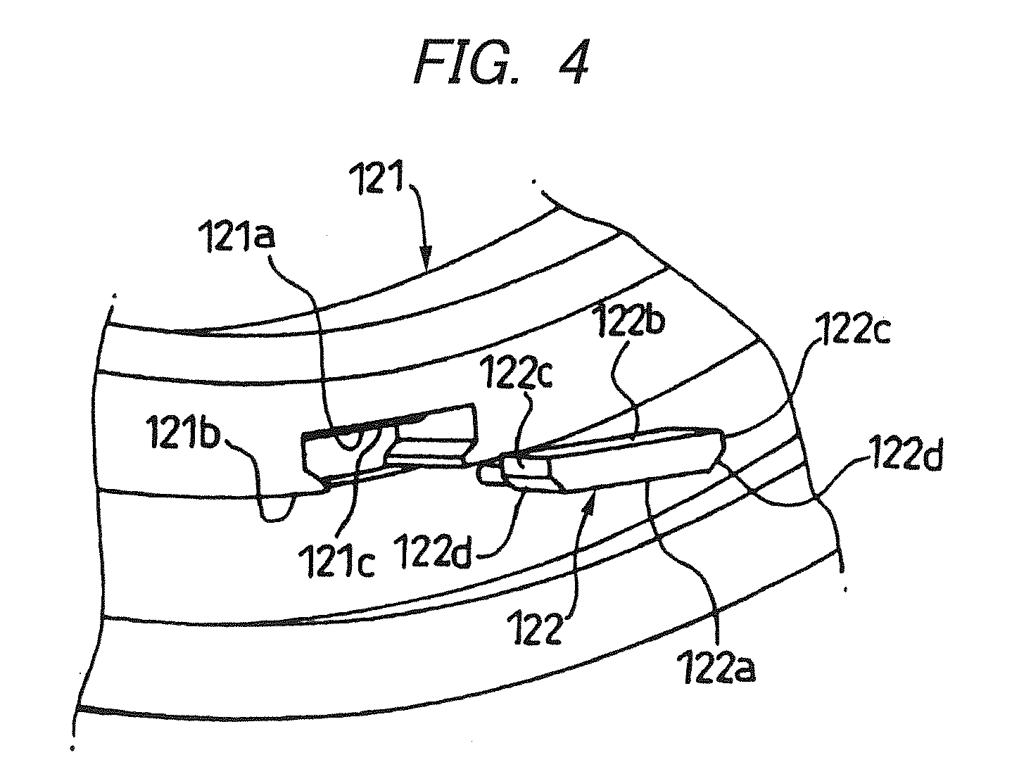
- Fig. 4 is the enlarged perspective view showing the element parts around the sensor attaching groove of the sensor holder.
- the rolling bearing 111 has the inner ring 12 as the rotary-side bearing ring, the outer ring 13 as the stationary-side bearing ring, and a plurality of rolling elements 11 rotatably interposed between the inner ring 12 and the outer ring 13.
- the plurality of rolling elements 11 are held by the holder 14 equidistantly in the circumferential direction.
- the sensor 120 is furnished.
- the sensor 120 comprises the sensor body 122 supported by the ring shaped sensor holder 121, a later mentioned circuit substrate 123, and the multi-polar magnets (encoders) 125 fixed to the inner ring (the bearing ring at the movable side) 12 via the core metal 124 of the magnetic material, and is housed in the sensor cover 126.
- the multi-polar magnet 125 rotates together with the inner ring 12.
- the sensor body 122 is provided with the two Hall ICs with a decided angle such that it is possible to detect the movement in the rotating direction and the number of rotation of the multi-polar magnet 125.
- the angle of the two Hall ICs is preferably decided such that phases of output wave are 90° at an electrical angle.
- the sensor cover 126 is formed by sheeting a metal sheet of, e.g., the magnetic material, and includes a ring shaped part 126a housing the sensor 120 inward, a flange part 126b at one end side in the axial direction (the left side in Fig. 2 ) of the ring shaped part 126a, and a side face 126c at the other side in the axial direction (the right side in Fig. 2 ).
- the sensor cover 126 is secured to the outer ring 13 by fitting the flange part 126b on the outer circumference of the outer ring (the rolling bearing of the stationary side) 13 of the rolling bearing 111.
- the sensor holder 121 includes, e.g., a synthetic resin, having a decided elasticity, and is fitted inward of the sensor cover 126. At this time, the face of the outer diameter of the sensor holder 121 is fitted to the inner circumference of the sensor cover 126, leaving a predetermined space.
- the sensor holder 121 is, as shown in Fig. 4 , defined in a decided position with a sensor attaching groove 121 a which is provided with a step portion 121c for limiting a place of the sensor body 122 in the axial direction, and which is fitted (snapping engagement) with the sensor body 122 with a determined tightening margin owing to elastic deformation of the sensor holder 121.
- the sensor body 122 is attached under such a condition fitted in a manner that a bottom face 122b, a side face 122c and an oblique face 122d are engaged with the respectively corresponding faces of the sensor attaching groove 121 a. At this time, the sensor body 122 is attached such that a front end 122a slightly projects than an edge of the sensor attaching groove 121a of the sensor holder 121. Therefore, as shown in Fig. 1 , since the sensor 122 approaches at the front end 122a the side of the multi-polar magnet 125, the detecting precision of the sensor 122 more goes up.
- the sensor holder 121 is provided with a plurality of positioning pins 127 respectively projecting in the axial direction with determined spaces in the circumferential direction.
- the sensor cover 126 is provided with a plurality of fitting holes 126d in the circumferential direction with determined spaces.
- the respective positioning pins 127 pass through the corresponding fitting holes 126d, thereby to position the sensor cover 126 and the sensor holder 121.
- Each of the positioning pins 127 penetrated in the fitting holes 126d is elastic-deformed at its front end (the right end in Fig. 2 ), whereby the sensor cover 126 and the sensor holder 121 are fixed each other.
- the front end of the positioning pin 127 is made a hemispherical shape having a plane portion 127a by the plastic-deformation. Then, the plane portion 127a is positioned slightly inward (the left side of Fig. 2 ) than the side part 126c.
- the plastic deformation there are listed thermal deformation by heating, laser deposit, or supersonic welding.
- the respective fitting holes 126d are made in corresponding positions to the respective positioning pins 127 in the sensor cover 126 along the axial direction (left and right in Fig. 1 ).
- the circumferential edge of the fitting hole 126d in the sensor cover 126 forms a projection 126e standing toward the side of the sensor holder 121 (the left side of Fig. 1 ).
- the sensor cover 126 engages the sensor holder 121 or the circuit substrate 123 so as not to contact other parts than the projection 126e.
- the circuit substrate 123 causes the positioning pin 127 of the sensor holder 121 fitted in the hole 126d of the sensor cover 126 to pass through a through-hole 123a bored in a corresponding position, and is kept between the sensor cover 126 and the sensor holder 121.
- the circuit substrate 123 is mounted with an electronic circuit (not shown) processed signals by the sensor body 122.
- the contacting position between the circuit substrate 123 and the sensor cover 126 is limited to a position other than the electronic circuit of the circuit substrate 123 by means of the projection 126e formed in the circumferential part of the fitting hole 126d. This manner avoids a short circuit caused by contacting the electronic circuit of the circuit substrate 123 and the sensor cover 126.
- the sensor body 122 of the sensor 120 is fitted in the sensor attaching groove 121 a formed in the determined position along the circumferential direction in the sensor holder 121 with the decided tightening margin in company with the elastic deformation of the sensor holder 121, and is positioned easily and at high precision.
- the sensor holder 121 is fitted inward of the sensor cover 126 with the determined space.
- the positioning pins 127 of the sensor holder 121 are inserted in the corresponding fitting holes 126d of the sensor cover 126, and the sensor cover 126 and the sensor holder 121 are positioned at high precision without requiring the complicated process as the inserting formation.
- the positioning pins 127 of the sensor holder 121 pass through the fitting holes 126d under the condition of inserting the positioning pins 127 in the fitting holes 126d, and the inserted positioning pin 127 is plastic-deformed at the front end. Accordingly, in case an external force as the vibration is affected, the sensor body 122 is certainly prevented from dropping or dislocation.
- the positioning pin 127 of the sensor holder 121 passes through the through-hole 123a defined in the position corresponding to the circuit substrate 123, and is inserted in the fitting hole 126d corresponding to the sensor cover 126.
- the circuit substrate 123 is positioned at high precision between the sensor cover 126 and the sensor holder 121, and is held.
- the circumferential parts of the respective fitting holes 126d in the sensor cover 126 form the projections 126e standing toward the side of the sensor holder 121, and the only projections 126e engage the sensor cover 126 and the sensor holder 121 or the circuit substrate 123.
- the contacting position between the sensor cover 126 and the circuit substrate 123 is limited to the position other than the electronic circuit of the circuit substrate 123. This manner exactly avoids the short circuit caused by contacting the electronic circuit of the circuit substrate 123 and the sensor cover 126.
- the sensor body 122 of the sensor 120 is fitted in the sensor attaching groove 121 a defined in the determined position along the circumferential direction in the sensor holder 121 owing to the elastic deformation of the sensor holder 121 with the decided tightening margin. Therefore, the sensor body 122 can be positioned easily and at high precision without requiring the complicated process as the insert form, whereby it is possible to provide, at lower costs, the sensor-bearing apparatus 110 having the highly detecting precision.
- Fig. 5 is the whole cross sectional view showing the sensor-bearing apparatus as a second embodiment of the invention.
- the rolling bearing 211 is provided with magnetically sensitive sensor 220 at one side in the axial direction (the right side of the same).
- the basic structures of the rolling bearing 211 and the magnetically sensitive sensor 220 are similar to those of the first embodiment shown in Fig. 1 except parts to be mentioned in detail in the following, and the explanation is omitted by giving the same numerals.
- the conductive member 228 having the electromagnetic shielding effect is formed as one body with the sensor holder 121 in the inner circumference of the sensor holder 121.
- the conductive member 228 covers the inner circumference of the sensor holder 121, and shields electromagnet acting in the direction from the inner diametrical side of the bearing to the sensor body 122.
- the conductive member 282 includes iron powder, magnetic powder, resin mixed with carbon black rubber, paint or adhesive.
- the magnetically sensitive sensor 220 may be structured to have the position detecting Hall IC and the rotation number detecting Hall IC, instead of furnishing the two Hall ICs with the determined angle.
- the bearing inner diametrical side of the sensor body 122 is shielded from the electromagnet by means of the conductive member 228 having the electromagnetic shielding effect
- the multi-polar magnet (the encoder) 125 is disposed between the sensor body 122 and the sensor holder 121.
- the leakage magnetic flux directing from the bearing inner diametrical side to the outer diametrical side is, as shown with arrows in Fig. 5 , prevented from entering into the sensor cover 126 by the conductive member 228, and detours along the surface of the sensor cover 126.
- the leakage magnetic flux does not flow into the sensor body 122, the detecting signal influencing the leakage magnetic flux is not issued.
- each of the sensor body 122 and the multi-polar magnet 125 is shielded by the conductive member 228 from the leakage magnetic flux directing from the bearing inner diametrical side to the outer diametrical side, and the leakage magnetic flux is effectively bypassed.
- the sensor- bearing apparatus 210 can avoid erroneous actions of the magnetically sensitive sensor 220.
- the magnetic field reversely flows in the parts of the core metal 126 ⁇ the multi-polar magnet 125 ⁇ the sensor body 122, and the magnetic field is difficult to flow, so that the majority of the invading leakage magnetic flux is bypassed to other parts.
- Fig. 6 is the whole cross sectional view showing the sensor-bearing apparatus as a third embodiment of the invention.
- the sensor cover 231 is formed with a conductive member, instead of the conductive member (see Fig. 5 ) formed as one body with the above mentioned sensor holder 121.
- the sensor cover 231 comprises an outer diametrically ring shaped portion 231a enabling to house the magnetically sensitive sensor 220 therein, a flange portion 231b provided at one end side in the axial direction (the left side in Fig. 6 ) of the outer diametrically ring shaped portion 231 a, a side face 231c at the other end side in the axial direction (the right side in the same) of the outer diametrically ring shaped portion 231a, and an inner diametrically ring shaped portion 231d provided at the bearing inner diametrical side end of the side face 231 c.
- the sensor cover 231 is secured to the outer ring 13 by mounting the flange part 231b on the inner circumference 13b of the outer ring (the bearing ring of the stationary side) of the sensor-bearing apparatus 230.
- the sensor cover 231 covers the outer whole of the sensor holder 232 except the bearing side (the right side of Fig. 6 ) thereof for shielding the electromagnet of the magnetically sensitive sensor 220 to the sensor body 122.
- the sensor cover 231 has the function of fixing the sensor body 122 to the outer ring 13 and bypassing the external leakage magnetic flux.
- the leakage magnetic flux directing from the bearing inner diametrical side to the outer diametrical side is, as shown with arrows in Fig. 6 , prevented from entering into the sensor cover 231 by the inner diametrically ring shaped portion 231d of the sensor cover (the conductive member) 231, and detours along the surface of the sensor cover 231.
- the leakage magnetic flux does not flow into the sensor body 122, the detecting signal influencing the leakage magnetic flux is not issued.
- the sensor body 122 of the magnetically sensitive sensor 220 is shielded from the electromagnet by means of the sensor cover 231 formed with the conductive member, and the multi-polar magnet 125 is disposed between the sensor body 122 and the sensor holder 232.
- the sensor-bearing apparatus 230 can avoid erroneous actions of the magnetically sensitive sensor 220.
- the invention is not limited to the above mentioned embodiments, but appropriate deformations and improvement are available.
- sensors of other types may be employed.
- Fig. 7 is the cross sectional view showing the sensor- rolling bearing as a fourth embodiment of the invention.
- the basic structure of the sensor-rolling bearing 310 is similar to that of the first embodiment shown in Fig. 1 except parts to be mentioned in detail in the following, and the explanation is omitted by giving the same numerals.
- the seal 15 is expanded toward the inner ring 12 in the vicinity of one side of the outer ring 13, and the seal 15 covers the bearing space under the condition that the seal 15 contacts both of the inner ring 12 and the outer ring 13.
- the outer ring 13 is defined with a concave groove 16 in the end of the outer diametrical face thereof along the circumferential direction of the outer ring 13.
- the sensor portion 330 of the sensor-rolling bearing 310 comprises the sensor cover 331 as the attaching member, the magnet holder 332 as the attaching member, the magnetically sensitive sensor 333, the magnet 334 as a magnetic part to be detected, a spacer 335, the circuit substrate 336, and the sensor positioning member 337.
- the sensor cover 331 is the ring shaped magnetic member having a rectangular shape viewed in cross section, and is secured in that one end 331a is caulked in the concave groove 16 formed in the outer diametrical face 12b of the outer ring 12.
- Figs. 8(a) and 8(b) are views showing a method of caulking and securing one end 331 a of the sensor cover 331 in the concave groove 16 formed in the outer diametrical face 13b of the outer ring 13.
- caulking screws 401 are equidistantly provided in the circumferential direction of the ring shaped sensor cover 331, that is, disposed in an equiangular arrangement in positions of nZ ⁇ X.
- the caulker 400 forces to tighten the caulking screws 401, so that the front end 401a of the caulking screw 401 firmly secures one end 331a of the sensor cover 331 into the concave groove 16.
- n is a positive integer
- Z is the number of balls in the bearing
- X is the positive integer of 2 or more. That is, the number of caulking positions is desirably prime.
- the sensor cover to be caulked and secured may employ such a sensor cover 340 equidistantly formed cutouts in one end as shown in Fig. 8(c) .
- the rolling bearing has waviness of comparatively large top height in the bearings of the inner ring and the outer ring, abnormal noises are issued or the bearing is vibrated at constant frequency.
- the bearing of such waviness is mounted on a shaft, the shaft is subjected to especial whirling movements undesirably in practice. Abnormal noises or vibrations are generated when the number of waviness is nZ or nZ ⁇ X.
- the caulking has probability of deforming the outer ring or the inner ring of the bearing, and generating waviness of nZ or nZ ⁇ X. Accordingly, this embodiment specifies the number of caulking position to be nZ ⁇ X (X ⁇ 2) for preventing generation of vibration in order not to create waviness of nZ or nZ ⁇ X.
- the sensor cover 331 holds the magnetically sensitive sensors 33 at the decided positions via the sensor positioning member 337 on the side face of the inside end parts in rectangular shape in cross section.
- the magnetically sensitive sensor 333 is connected to the circuit substrate 336 disposed via the spacer 335 on the side face of the more inside in rectangular shape.
- the circuit substrate 336 is connected to a cable wire 338 for outputting outside from the sensor body 333.
- the magnet holder 332 is the ring shaped magnetic member whose front ends are bent to face the front ends of the sensor cover 331.
- the magnet holder 332 is forced to be fixed in the outer diametrical end part 12b of the inner ring 12.
- the magnet holder 332 extends toward the side of the outer ring 13 to close the bearing space from the inner ring 12, and functions as a cover shielding the bearing space.
- the magnet holder 332 holds the magnet 334 on the front end facing the magnetically sensitive sensor 333. With this arrangement, the sensor cover 331 and the magnet holder 332 hold the magnetically sensitive sensor 333 and the magnet 334 at the places not to expose the outside.
- the sensor cover 331 and the magnet holder 332 include the magnetic material, and therefore functions as the magnet shield not to transmit variations in the magnetic field caused by the magnetic noises to the magnetically sensitive sensor 333 and the magnet 334. If using, as the material of the magnet 334, neodymium-iron-boron (Nd-Fe-B) or samarium-cobalt (Sm-Co), resistance to the external magnetism is more increased.
- Fig. 9 is the cross sectional view showing the magnetically sensitive sensor and the sensor positioning members.
- the sensor positioning member 337 is the ring shaped member on the sensor cover 331. The sensor positioning member is so disposed as to be concentric with the rotating center of the shaft.
- the sensor positioning member 337 of this embodiment is defined with three concaves 337a for fixedly positioning the magnetically sensitive sensor 333 in the outer diametrical face, and each of the concaves 337a is inserted with the magnetically sensitive sensor 333.
- the magnetically sensitive sensors 333 are disposed in the same circumference at the determined angular space with respect to the rotation center of the shaft.
- the number of the magnetically sensitive sensors 333 to be attached can be varied into arbitrary number in response to usage of the sensor-rolling bearing, while the number of the concaves 337a to be formed in the sensor positioning member 337 is also varied into arbitrary number in response to the number of the sensors.
- the structure of this embodiment is for detecting a phase angle of each phase of a three-phase motor, and for detecting the rotation speed of the shaft, at least one sensor is enough, and for detecting the rotating direction at the same time, two sensors are sufficient.
- Fig. 10 is the cross sectional view showing the structure of the magnet 334.
- the magnet 334 is fixed at the outer diametrical face to the magnet holder 332, and is opposite to the magnetically sensitive sensor 333 and the sensor positioning member 337.
- the magnet 334 is structured in that eight pieces of N poles 334a of the same shape and eight pieces of S poles 334b are alternately connected in ring.
- the magnet 334 is, similarly to the sensor positioning member 337, disposed to be concentric with the shaft rotating center, and rotates together with the rotation of the inner ring 12. Being concentric with the sensor positioning member 337, the distance between the magnet and the magnetically sensitive sensor 333 is not changed, irrespective of the rotating position of the magnet 334.
- Each of N poles 334a and S poles 334b is arranged such that the magnetic flux density is made strong in the direction of the magnetically sensitive sensor 333.
- the number of the magnetic poles of the magnet 334 is varied into arbitrary number in response to using conditions of the sensor-rolling bearing 310 similarly to the number of the magnetically sensitive sensor 333.
- the magnetically sensitive sensor 333 rotates together with rotation of the shaft, detects intensity of the magnetic field formed by each magnetic pole of the magnet 334, and outputs it as an electric signal.
- the output electric signal is sent to the circuit substrate 336 through the signal wire, subjected to a predetermined process, and then output through the signal wire 338 to a measuring device installed outside.
- the measuring device is based on the received electric signal to obtain information such as rotation speed, rotating direction and phase angle of the three phases.
- the sensor-rolling bearing 310 of the fourth embodiment is secured in that the sensor cover 331 holding the magnetically sensitive sensor 333 caulks the plural positions in the concave groove 16 defined in the outer diametrical face of the outer ring 13. Further, the magnet holder 332 holding the magnet 334 is forced to fix the end of the inner ring 12. Therefore, it is possible to dispose the magnetically sensitive sensor 333 and the magnet 334 in the right position, without providing the step portion of much dispersion in size.
- the sensor cover 331 and the magnet holder 332 of a blank being the magnetic material shield the external magnetic field, so that no fear exists that variations of the external magnetic field give influences to the magnetically sensitive sensor 333 and the magnet 334. Thus, the accurate measure is possible not being affected by variations of the external magnetic field.
- the magnet 334 is positioned at the outer diametrical side of the magnetically sensitive sensor 333, and the outer diametrical side of the magnet 334 is supported by the magnet holder 332. Therefore, the present structure avoids breakage of the magnet 334 by strong centrifugal force generated when the shaft rotates at high speed.
- the number of caulking positions is determined to be nZ ⁇ X (X ⁇ 2), it is possible to restrain occurrence of waviness of nZ or nZ ⁇ 1 piece in the raceway surface of the bearing owing to deformation by caulking. Therefore, it is possible to provide the sensor-rolling bearing of high precision without issuing abnormal noises or vibrations.
- the sensor-rolling bearing 310 of this embodiment may be applied as the bearing of the shaft used to automobiles, railway carriers, iron-making facilities, or machine tools for detecting rotation speed of shafts of various devices.
- Fig. 11 is the cross sectional view showing the sensor- rolling bearing as a fifth embodiment of the invention.
- the sensor-rolling bearing 350 comprises the inner ring 351 mounted on the shaft, the outer ring 352 fitted in the housing, balls 353 as the rolling elements rolling along an inner ring raceway 351a and an outer ring raceway 352a respectively formed in the outer diametrical face of the inner ring 351 and in the inner diametrical face of the outer ring 352, a holder 354 holding the balls 353, and the shielding plate 355 standing from the vicinity of one side of the outer ring 352 toward the inner ring 351 for covering the vacancy of the bearing defined between the inner ring 351 and the outer ring 352.
- This embodiment defines a concave groove 351b along the circumferential direction of the inner ring 351 nearly one end of the outer diametrical face 351b of the inner ring 351.
- the sensor portion 360 of the sensor-rolling bearing 350 comprises the sensor cover 361 as the attaching member, the magnet holder 362 as the attaching member, the magnetically sensitive sensor 363, the magnet 364 as the magnetic part to be detected, the spacer 365, the circuit substrate 366, and the sensor positioning member 367.
- the sensor cover 361 is the ring shaped magnetic member of L-shape.
- the sensor holder 361 has one end which is forced to be secured in the concave groove 352c formed along the circumferential direction on the inner diametrical face of the end 352b of the outer ring 352.
- the sensor cover 361 is provided at the L-shaped other end with the sensor positioning member 367 in parallel in the axial direction.
- the sensor positioning member 367 has the magnetically sensitive sensor 363 at the decided part.
- the magnetically sensitive sensor 363 is connected to the circuit substrate 366 disposed on the L-shaped inside face via the spacer 365.
- the circuit substrate 366 is connected to a cable wire 368 for outputting outside from the sensor body 363.
- the magnet holder 362 is the ring shaped magnetic member whose front ends are bent to face the front ends of the sensor cover 361.
- one end 362a of the magnet holder 362 is caulked to be fixed in the concave groove 351b formed in the circumferential direction along the outer diametrical face of the inner ring 351.
- This embodiment specifies the number of caulking positions to be nZ ⁇ X (X ⁇ 2) for preventing generation of vibration.
- the magnet holder 362 extends to the side of the outer ring 352 to close the bearing space from the inner ring 351, and functions to shield the bearing space.
- the magnet holder 362 holds the magnet 364 on the front end facing the magnetically sensitive sensor 363. With this arrangement, the sensor cover 361 and the magnet holder 362 hold the magnetically sensitive sensor 363 and the magnet 364 at the places not to expose the outside.
- the sensor cover 361 and the magnet holder 362 include the magnetic material, and therefore functions as the magnet shield not to transmit variations in the magnetic field caused by the magnetic noises to the magnetically sensitive sensor 363 and the magnet 364.
- the magnetically sensitive sensor 363 and the magnet 364 have the structures equivalent to those of the magnetically sensitive sensor 333 and the magnet 334 of the fourth embodiment.
- the sensor-rolling bearing 350 of the fifth embodiment is secured in that the sensor cover 361 holding the magnetically sensitive sensor 363 is forced to be fixed in the end of the inner ring 351. Further, the magnet holder 362 holding the magnet 364 is fixed by caulking, in the plural positions, one ends 362a in the concave groove 351b formed in the outer diametrical face of the inner ring 351. Therefore, it is possible to dispose the magnetically sensitive sensor 363 and the magnet 364 in the right position, without providing the step portion of much dispersion in size.
- the magnet 364 is positioned at the outer diametrical side of the magnetically sensitive sensor 363, and the outer diametrical side of the magnet 334 is supported by the magnet holder 362. Therefore, the present structure avoids breakage of the magnet 364 by strong centrifugal force generated when the shaft rotates at high speed.
- the number of caulking positions is determined to be nZ ⁇ X (X ⁇ 2), it is possible to restrain occurrence of waviness of nZ or nZ ⁇ 1 pieces in the raceway surface of the bearing owing to deformation by caulking. Therefore, it is possible to provide the sensor-rolling bearing 350 of high precision without issuing abnormal noises or vibrations.
- the sensor-rolling bearing 350 of this embodiment may be applied as the bearing of the shaft used to automobiles, railway carriers, iron-making facilities, or tool machines for detecting rotation speed of shafts of various devices.
- the sensor-rolling bearing of the sixth embodiment according to the invention is shown in Fig. 12 .
- the basic structure of the rolling bearing 501 of the sensor-rolling bearing 500 is the same as that of the first embodiment shown in Fig. 1 except parts to be mentioned under in detail, and the explanation will be omitted by giving the same numerals.
- the holder 14 is a plastic-made crown, and a ring shaped shielding plate 15 is secured to a side opposite to a ring portion 14a which is a closed side of the crown shaped holder 14, the plate 15 being mounted in the fitting groove 13a of the outer ring 13, and non-contacted to the inner ring 12.
- the core metal 124 as the magnet attaching member forms a cylindrical part 517 bent in the axial direction of the bearing in the outer circumference, and the outer circumference 518 of the cylindrical part 517 is opposite to an inner circumferential end 13c of the outer ring 13, leaving a slight space.
- the multi-polar magnet 523 in ring and plane shape is disposed as contacting the side face 521 of the core metal 124 and the circumferential face 522 of the cylindrical part 517, and an adhesive is interposed at a part of contacting the multi-polar magnet 523 to the side face 521 and the circumferential face 522, so that the multi-polar magnet 523 is firmly secured to the core metal 124.
- the multi-polar magnet 523 has the magnetic poles as changing alternately in the circumferential direction.
- the step portion 524 of a ring shaped groove formed at the end part of the outer circumferential face 13d of the outer ring is fixedly fitted with a fixing cylindrical part 526 of the sensor cover 525 of the magnetic substance, while a step 527 formed in the sensor cover 525 contacts the side face of the outer ring 13 for positioning.
- the sensor cover 525 comprises a cylindrical holder 528 extending in the axial direction of the bearing and a cylindrical holder 529 extending from the front end of the cylindrical holder 528 toward the inside in the radius direction, and a resin made base plate holder 530 is disposed as contacting the cylindrical holder 528 and cylindrical holder 529, and the adhesive is interposed at their contacting part, so that the resin made base plate holder 530 is fixedly adhered to the sensor cover 525.
- the resin of forming the base plate holder 530 for example, 66 nylon including glass fiber, 44 nylon or PPS may be used.
- the circuit substrate 531 is fixed to the face opposite to the multi-polar magnet 523 in the base plate holder 530, and on the circuit substrate 531, the Hall IC 533 is soldered via a decided space from the side 532 of the multi-polar magnet 523.
- the circuit substrate 531 is appropriately soldered with various electric parts 534 such as a noise canceling resistor or a capacitor.
- the base plate holder 530 is extended at one part to make a cable taking-out portion 535.
- the cable taking-out portion 535 may be an independent body, but it is desirable to make one body as above mentioned, since the number of parts is less. If mounting the electric parts such as the noise canceling resistor or the capacitor on the circuit substrate 531, a sensor-bearing excellent in noise resistance may be realized.
- the Hall IC 533 soldered on the circuit substrate 531 is sufficient with a lead type, but a Hall IC of a surface mounting type may be used, which is easy to solder and can attain a cost-down.
- a Hall IC of a surface mounting type may be used, which is easy to solder and can attain a cost-down.
- various electronic parts as the noise canceling resistor or the condenser other than the Hall elements if using the surface mounting typed resistor or condenser, all parts can be soldered by one process, and more desirably the production may reduce cost.
- magnetically sensitive element optional ones of the conventionally used magnet detecting elements such as Hall elements, MR elements or MI elements other than the Hall IC 533 may be selected and used.
- the outer circumferential face 518 of the cylindrical part 517 formed at the outer circumference of the core metal 124 faces the inner circumferential face 13c of the outer ring 13 with a slight space, is arranged to close the bearing space, and a grease in the bearing space is difficult to leak away outside.
- the core metal 124 is made of the magnetic substance, the leakage magnetic flux passing the rolling elements can be checked from going to the multi-polar magnet 523 or the Hall IC 533 owing to existence of the intensive magnetism occurring part in the outside. As a result, any miss-count of the speed pulse by an erroneous operation of the Hall IC 533 is absent, enabling to heighten the pulse measuring precision.
- the core metal 124 may be served as an interrupting member of the magnetic flux, other parts are unnecessary and the cost is reduced. If making the sensor cover 525 of the magnetic substance, an external magnetic flux can be interrupted by the sensor cover 525 of the magnetic substance. The magnetic flux of the multi-polar magnet 523 can be avoided from leaking outside.
- the positioning is preferably made easy when attaching the multi-polar magnet 523. If filling the adhesive in the space to support the outer circumference of the multi-polar magnet 523 with the cylindrical part 517, the multi-polar magnet 523 can be more preferably prevented from centrifugal breakdown.
- the multi-polar magnet 523 in plane shape is used, and the magnetically sensitive element such as the Hall IC 533 is arranged, so that the thickness in the axial direction in the whole of the rolling bearing 501 can be reduced to be thin, and in particular the multi-polar magnet 523 can be arranged at the part inherently providing the seal for protecting the inside of the rolling bearing 501, and since at least either of both plane sides of the multi-polar magnet 523 can be disposed inside than the end of the rolling bearing 501, the size in the axial direction of the whole of the rolling bearing 501 can be further shortened.
- the disposing position in the bearing axial direction of the multi-polar magnet 523 is determined, and as shown in Fig. 12 , employing the crown shaped plastic holder, if disposing the sensor in a side of opening the crown of the holder, the size in the axial direction can be more preferably reduced.
- the core metal 124 desirably employs the magnetic substance for performing magnetism interruption as mentioned later, an iron, martensite or ferrite based stainless steels are available. If using the iron as mentioned above, treatments as Zn or Ni plating or coating are desirable.
- the inner ring 12 is made a flat face, not defining the groove, and a flange to be urged to the flat face is formed in the core metal 124, and is attached by forcing to press.
- a seventh embodiment of the invention is shown in Fig. 13 .
- a securing cylinder 542 of the core metal 541 as a magnet attaching member is fixedly fitted in the step portion 543 defined in the inner circumferential face of the inner ring 12.
- the same shielding plate 544 as the shielding plate 15 provided at the left side in the drawing of the rolling element 11 is also provided at the right side in the same of the rolling element 11.
- a point of arranging the Hall IC 533 soldered to the circuit substrate 531 supported by the sensor cover 525 in such a manner that a determined space is formed in relation with the side face 532 of the multi-polar magnet 523 attached to the core metal 541, is the same as in the sixth embodiment, and a detailed explanation is omitted.
- the core metal 541 is fixed to the inner circumferential face of the inner ring 12 as mentioned above, thereby to employ the structure of providing the shielding plates 15, 544 at the left and right of the rolling element 11, so that the conventionally used bearing cover (the bearing shield) can be used as it is, and the protection of the bearing inside can be exactly performed, and concurrently the grease filled in the interior can be checked from flowing outside.
- FIG. 14 An eighth embodiment is shown in Fig. 14 .
- This embodiment uses a contacting rubber seal 546 as the bearing seal.
- the structures of the multi-polar magnet and the sensor are the same as in the seventh embodiment shown in Fig. 13 , and an explanation thereof is omitted.
- the size in the axial direction of the rolling bearing is longer in comparison with that of the sensor-rolling bearing of the sixth embodiment shown in Fig. 12 , but it can be shorter than the conventional one, and particularly, since the inherent seal of the rolling bearing can be served as it is, the sealing performance of the rolling bearing is not spoiled.
- the core metals 124, 541 as the magnet attaching member are arranged as closing the bearing space, and even if the bearing seal is absent there, the grease can be prevented from leakage.
- the magnetic flux leaking to the sides of the multi-polar magnet 523 or the Hall IC 533 through the rolling elements 11 can be interrupted by these core metals 124, 541, and erroneous operations when detecting the speed pulse can be made naught.
- the magnetic substance is desirable for interrupting the magnetism, and then, the iron, martensite or ferrite based stainless steels are available.
- the seventh and eighth embodiments exemplify that the plane multi-polar magnet 523 is secured to the side of the inner ring 12 being the rotating ring, and in case the rotating ring is the outer ring 13, the multi-polar magnet 523 is attached to the outer ring 13 by the same technique as that of each embodiment using the core metal.
- the present application is based on the Japanese Patent Application filed October 28, 2002 (No. 2002-312772 ), the Japanese Patent Application filed December 13, 2002 (No. 2002-362635 ), the Japanese Patent Application filed January 7, 2003 (No. 2003-001159 ), the Japanese Patent Application filed January 10, 2003 (No. 2003-004493 ), and the Japanese Patent Application filed August 27, 2003 (No. 2003-303736 ).
- the senor can be positioned easily and at high precision, not requiring any complicated process as resin inserting formation, and further the leakage magnetic flux from the outside can be effectively bypassed, so that any erroneous operation of the sensor caused by electricity or magnetic noises of the motors can be prevented.
Landscapes
- Engineering & Computer Science (AREA)
- General Engineering & Computer Science (AREA)
- Mechanical Engineering (AREA)
- Physics & Mathematics (AREA)
- General Physics & Mathematics (AREA)
- Rolling Contact Bearings (AREA)
Abstract

Description
- The present invention relates to a bearing apparatus with a sensor and a rolling bearing with a sensor which are used to movers such as automobiles or railway carriers, machines of equipment, or machine tools, and in particular to a bearing apparatus with a sensor (called as "sensor-bearing apparatus" hereafter) and a rolling bearing with a sensor (called as "sensor-rolling bearing" hereafter) which are suited to detecting speed of rotation, direction of rotation, or phases by use of a Hall element or Hall IC.
- For example, nowadays in automobiles, control of anti-lock breaking system (ABS) or traction control system (TCS) have widely been practiced, and for the control, speed of rotation of wheels must be exactly detected. Therefore, speed of rotation (number of rotation) of a rolling bearing rotatably supporting the wheels with respect to a winding device has been detected.
- For detecting speed of rotation (number of rotation) of the rolling bearing, there has much served the sensor-rolling bearing with a rotating sensor installed nearly to the bearing. Namely, the sensor-rolling bearing performs detection of speed of rotation of the wheels in that a cylindrical magnet having many magnetic poles alternately arranged to a rotating side, detects a magnetic flux of the magnet rotating together with the wheels through a sensor using the Hall element or the Hall IC provided to a stationary side.
- The sensor-rolling bearing detects speed of the movers, not limiting to the above mentioned automobiles but including those having the rotating members of such as railway carriers, and the detection of the rotating direction has been also widely practiced. The sensor-rolling bearing has been employed, in many kinds of machines of equipment, for detection of rotation speed of a motor output shaft or that of pump.
- In the industrial wide field, for detecting number of rotation of the rotating members, that is, speed of rotation, or for detecting the rotating direction or phases of rotation, the sensor-rolling bearing has widely been used as the bearing of the rotating members.
- A sensor-bearing
apparatus 630 has conventionally been known as shown inFigs. 15 and 16. Fig. 15 is a whole cross sectional view showing the sensor-bearing apparatus, andFig. 16 is a cross sectional view along C - C line of the sensor-bearing apparatus ofFig. 15 . The sensor-bearingapparatus 630 causes oneend 641 of thesensor 640 to directly contact areference face 631a of a stationary-side bearing ring 631, while it causes cut-out faces 633 of asensor holding element 632 to fix chamferedparts 642 of thesensor 640 in order to position the sensor 640 (for example, Japanese Patent Laid Open No.311740/1998 - The above mentioned conventional sensor-bearing
apparatus 630 has been involved with a problem that aconnection output portion 634 or aconductor 635 are applied with external force or vibration, so that a position of thesensor 640 is circumferentially dislocated. Then, an error in output of thesensor 640 is probably caused by the circumferential dislocation. - Therefore, the sensor-bearing
apparatus 630 depends on resin insertion between thesensor holding element 632 and thereference face 631 a of the stationary-side bearingring 631 for checking the circumferential dislocation. - However, depending on the resin insertion, since a complicated process is required, there is a room for making improvement with respect to production process and cost-up, accordingly.
-
Fig. 17 is a cross sectional view of the element parts showing the conventional sensor-rolling bearing. This sensor-rollingbearing 700 is formed by securing a magneticallysensitive sensor 721 and a member 720 to be detected such as a magnet to theouter ring 710 or theinner ring 711. - The magnetically
sensitive sensor 721 buried in asensor carrier 723 includes a beading fixture over a full length of aconcave groove 716 formed in an inner diametrical face of the outer ring via asensor holding device 725. In addition, the member to be detected 720 is disposed on a plane part in the radius direction of an L-shaped member 722 forced in an outer diametrical face, so that the member 720 to be detected faces to thesensor 721. - In the above mentioned conventional sensor-rolling
bearing 700, if a size of the bearing is small in the diametrical direction, it is difficult to secure the magneticallysensitive sensor 721 to the inner diametrical face of theouter ring 710 via thesensor carrier 723. It is also difficult to secure the member to be detected 720 to the outerdiametrical face 711 of the inner ring via the L-shaped member 722. - For solving this problem, as seeing
Figs. 18 and19 , it may be assumed to provide a step portion in the outer diameter of the outer ring or the inner ring in order to fix the sensor or the member to be detected. But since a face to be processed of the step portion cannot be subjected to a centerless machining, sizes are largely dispersed, and it is difficult to force and fix respective members. - In general, the sensor-rolling bearing is very often disposed nearly members generating electric noises by a motor. Therefore, by disposing locations, an external magnetic field caused by an external noise disturbs a magnetic field formed by the member to be detected, so that such probability might be caused that the sensor cannot exactly detect the magnetic field formed by the member to be detected.
- Further, the sensor-bearing
apparatus 800 as shown inFig. 20 is known.Fig. 20 is a cross sectional view of the element parts of the conventional sensor-bearing apparatus. As showing in the same, the sensor-bearingapparatus 800 is structured in that themagnetic sensor 802 of therotating sensor 801 and a pulsar ring (encoder) 803 are shielded with a sensorcase fixing ring 804 of a magnetic substance and amagnetic bypass 805 so as to bypass an external leakage flux (for example, Japanese Patent Laid Open No.2002-174258 - As another embodiment of the conventional sensor-bearing
apparatus 800, there are those shown inFigs. 21 and 22. Fig. 21 is a whole cross sectional view of the element parts showing another example of the conventional sensor-bearingapparatus 800, andFig. 22 is an upper (seeing from an upper side ofFig. 21 ) and partially plan view ofFig. 21 . - Referring to
Figs. 21 and 22 , in the conventional sensor-bearing 850, theinner ring 852 at the right side ofFig. 21 of therolling element 853 is secured at the outer circumferential end with acore metal 856 which is arranged with acylindrical pulsar ring 857 of a permanent magnet. Themagnetic sensor 860 is placed within thesensor case 858 leaving a space in relation with the outer circumferential face of thepulsar ring 857, while thesensor case 858 is fixed to an inside of a sensorcase fixing ring 861. - In regard to the sensor-bearing 850, the
magnetic bypass 862 is furnished to a further inside of the sensorcase fixing ring 861 fixed to theouter ring 851 for interrupting the leakage magnetic flux flowing from a coil of the external motor into themagnetic sensor 860. Further, the sensor-bearing 850 is furnished with aside plate 863 and at the same time with acutout window 861a at the upper part of amagnetic sensor 860 in the sensorcase fixing ring 861 for interrupting the loop of the leakage magnetic flux into themagnetic sensor 860. - However, the above mentioned conventional sensor-bearing 850 is disposed with the
magnetic sensor 860 such as Hall elements via thepulsar ring 857 and the space in the radius direction on the outer circumference of the cylindrical pulsar ring (magnet) 857 secured as projecting to the side of theinner ring 852. Therefore, for exactly detecting magnetic change of the rotatingpulsar ring 857 by means of themagnetic sensor 860, a surface part of thepulsar ring 857 opposite to themagnetic sensor 860 necessitates a length larger than decided particularly in the axial direction of the sensor-bearing 850. - Accordingly, the surface part of the
pulsar ring 857 opposite to themagnetic sensor 860 cannot but project by the length larger than decided in the axial direction of the sensor-bearing 850. - As a result, the above mentioned
magnetic sensor 860 has a limitation in shortening the length in the axial direction of the sensor-bearing 850, and cannot satisfy a requirement for saving a space requested for using the sensor-bearing to many kinds of devices, including speed detection of automobiles. - In addition, since the space between the
pulsar ring 857 and themagnetic sensor 860 extends in the axial direction, a grease filled in a vacancy of the bearing flows along the space in the axial direction, and is ready for running outside as it is, and therefore, an improvement has been demanded for. - Further, in case the leakage magnetic flux flows owing to an external intense magnetic flux into between the
inner ring 852 and theouter ring 853 of the sensor-bearing 850, the magnetic flux leaks to a side of thepulsar ring 857 or themagnetic sensor 860 via therolling element 853. It is therefore necessary to provide another member of a shielding plate such as amagnetic bypass 862 between the sensor-bearing 850 and themagnetic sensor 860, increasing the number of parts and heightening cost, and concurrently increasing a setting-up process. Besides, an installing space is required to restrain reduction in size. - It is accordingly an object of the invention to provide the sensor-bearing apparatus and the sensor-rolling bearing, which may bring about high productivity and cost saving effect, position the sensor easily and at high precision without requiring the complicated process as the formation of resin insertion, effectively bypass the leakage magnetic flux from the outside with the less number of parts in order to avoid erroneous action of the sensor caused by electric noises of the motor, and reduce in size by shortening the length in the axial direction.
- The above mentioned object of the invention can be accomplished by means of the under mentioned structures.
- In a rolling bearing structured in that a plurality of rolling elements held in a holder are rotatably incorporated between a pair of bearing rings, a bearing apparatus with a sensor, comprising
a sensor for detecting conditions of a supported rotating shaft or of the rolling bearing,
a ring shaped sensor cover secured to one end face in an axial direction of a stationary-side bearing ring, and
a ring shaped sensor holding member secured to the sensor cover,
wherein the sensor is fitted in a sensor holding groove provided in a determined position along a circumferential direction in the sensor holding member with a determined tightening margin owing to elastic deformation of the sensor holding member. - The sensor holding member is fitted inward of the sensor cover with a determined space.
- The sensor holding member is formed with a plurality of positioning pins as projecting respectively in the axial direction, leaving determined spaces in the circumferential direction, and the sensor cover is formed with a plurality of fitting holes in respective positions corresponding to the plurality of positioning pins, and
the plurality of positioning pins are fitted in the plurality of respectively corresponding fitting holes, whereby the sensor cover and the sensor holding member are positioned. - The plurality of positioning pins are respectively inserted in the plurality of fitting holes, and the plurality of positioning pins passing through the plurality of fitting holes are plastic-deformed at front ends, whereby the sensor cover and the sensor holding member are fixed.
- The plurality of fitting holes are formed in the circumference with projections standing toward the sensor holding member, and the sensor cover and the sensor holding member are engaged by means of the projections only.
- A circuit substrate of the sensor is held between the sensor cover and the sensor holding member, and the plurality of positioning pins of the sensor holding member pass through holes provided in the corresponding positions in the circuit substrate, and are inserted in the fitting holes.
- In a rolling bearing structured in that a plurality of rolling elements held in a holder are rotatably incorporated between a pair of bearing rings,
a bearing apparatus with a sensor, comprising
a sensor for detecting conditions of a supported rotating shaft or of a bearing,
a ring shaped sensor cover of a magnetic material secured to one end face in an axial direction of a stationary-side bearing ring,
a ring shaped sensor holding member of a non-magnetic material holding the sensor inward under a condition of being secured inward of the sensor cover, and
a conductive member installed as covering at least one part of the sensor holding member and has an electromagnetic shield effect. - In a rolling bearing structured in that a plurality of rolling elements held in a holder are rotatably incorporated between a pair of bearing rings,
a bearing apparatus with a sensor, comprising
a sensor for detecting conditions of a supported rotating shaft or of a bearing,
a ring shaped sensor cover of a conductive member having an electromagnetic shielding effect secured to one end face in an axial direction of a stationary-side bearing ring, and
a ring shaped sensor holding member of a non-magnetic material holding the sensor inward under a condition of being secured inward of the sensor cover. - The conductive member is provided as one body with the sensor holding member.
- A rolling bearing with a sensor, comprising an inner ring, an outer ring, rolling elements interposed between the inner ring and the outer ring, a magnetic part to be detected provided to one of the inner ring and the outer ring, and a magnetically sensitive sensor provided to the other of the inner ring and the outer ring and being opposite to the magnetic part to be detected,
wherein any one of the magnetic part to be detected and the magnetically sensitive sensor is secured to the inner ring or the outer ring via an attaching member of a magnetic substance. - The magnetic part to be detected is a ring shaped multi-pole magnet of rare earth.
- The attaching member is fixedly caulked in a concave groove formed in an outer diameter of the inner ring or the outer diameter of the outer ring.
- The concave groove is formed in the circumference along the outer diameter of the inner ring or the outer diameter of the outer ring, and the attaching members are caulked in a plurality of positions equidistantly along the circumference.
- The number of the caulking positions follows the under mentioned formula,
(the number of the caulking positions) = nZ ± X
herein,
n: positive integer
Z: the number of the rolling elements, and
X: integer of 2 or more - The number of the caulking positions is prime.
- In a rolling bearing having at least an outer ring, an inner ring, and rolling elements, any one of the outer ring and the inner ring is a rotating ring, while the other is a stationary ring,
a rolling bearing with a sensor, wherein an end face of a flat magnet is multi-pole magnet, and is secured to the rotating ring, and
a magnetically sensitive element is secured to the stationary ring in opposition to the flat multi-pole magnetic face, leaving spaces equidistantly in an axial direction of the bearing. - The the member of attaching the magnet to the rotating ring extends toward the stationary ring so as to close a vacancy of the bearing between the rotating ring and the stationary ring.
- The inner ring is the rotating ring, and the magnet attaching member is secured to a step portion in the inner circumference of the inner ring.
- In accordance with the sensor-bearing apparatus mentioned above, the sensor is secured in the sensor attaching groove formed in the sensor holder in that the tightening margin is effected with an elastic deformation of the sensor holder. Therefore, neither insertion of the resin nor use of an adhesive are requisite, and accordingly, the positioning is realized easily and at high precision.
- In accordance with the sensor-bearing apparatus mentioned above, it is possible to avoid the sensor cover from deformation caused by expansion and shrinkage of the sensor holder owing to temperature change, so that it is possible to avoid dropping of the sensor cover from the stationary-side bearing ring (for example, the outer ring) or deformation of the stationary-side bearing ring.
- In accordance with the sensor-bearing apparatus mentioned above, when inserting the respective positioning pins in the respectively corresponding fitting holes, the sensor cover and the sensor holder can be positioned at high precision without requiring the complicated process such as the resin inserting formation.
- In accordance with the sensor-bearing apparatus mentioned above, the positioning pins can be prevented from dropping from the fitting holes, depending on plastic-deformed parts. Accordingly, the above mentioned sensor-bearing apparatus can exactly prevent the sensor from dropping or dislocation even if applying the external force as vibration.
- Herein, as actual examples of the plastic deformation, there are listed thermal deformation by heating, laser deposit, or supersonic welding.
- In accordance with the sensor-bearing apparatus mentioned above, the holding pressure is kept high around the circumferences of the respective fitting holes, and the function of the positioning pin is heightened.
- In accordance with the sensor-bearing apparatus mentioned above, the sensor cover and the sensor holder are positioned, and at the same time, the positioning pins are passed into the through-holes formed in the circuit substrate, so that the circuit substrate is positioned and supported at high precision between the sensor cover and the sensor holder.
- This is such a structure where the sensor cover and the sensor holder or the circuit substrate are engaged only at the projection of the circumferential part of the fitting hole. Therefore, it is possible to limit the part of mutually contacting the circuit substrate and the sensor cover to, e.g., another part than a circuit of the circuit substrate. Thus, a short circuit by contact between the circuit of the circuit substrate and the sensor cover can be avoided certainly.
- In accordance with the sensor-bearing apparatus mentioned above, the sensor is shielded from electromagnet by a conductive member having an electromagnetic shielding effect, which is provided so as to cover at least one part of the sensor holding member. Therefore, the flow of the leakage magnetic flux from the outside is effectively bypassed (detour) by the electromagnetic shield depending on the conductive member.
- Further, the sensor-bearing apparatus according to the invention does not necessitate the sensor
case fixing ring path 805, or theside plate 863 as the sensor-bearingapparatus 800 or the sensor-rollingbearing 850 shown inFigs. 20 and21 . - Accordingly, the number of parts may be curtailed, and the setting-up process may be reduced.
- In accordance with the sensor-bearing apparatus mentioned above, the sensor cover includes the conductive member having the electromagnetic shielding effect. Therefore, the flow of the leakage magnetic flux from the outside is effectively bypassed (detour) by the electromagnetic shield depending on the conductive member. In addition, the number of parts may be further curtailed, and the setting-up process may be reduced.
- In accordance with the sensor-bearing apparatus and the sensor-rolling bearing mentioned in the above (12), the conductive member may be provided to the sensor holder at higher strength, and concurrently the number of parts may be further curtailed, and the setting-up process may be reduced.
- As a method of integrally forming the conductive member and the sensor holder, there are a 2-color molding of a conductive resin, adhesion or pressing into fixture. The conductive member includes iron powder, magnetic powder, resin or rubber mixed with carbon black, paint or adhesive.
- In accordance with the sensor-rolling bearing mentioned above, the attaching member being the magnetic substance functions as the magnetic shield to the external magnetic field, and reduces influences of the external magnetic field to the magnetic part to be detected and to the magnet sensitive sensor. Therefore, it is possible to heighten the detecting precision of the magnet sensitive sensor, and perform the exact measure.
- In accordance with the sensor-rolling bearing mentioned above, being exposed to an intensively magnetic environment, the capacity in the magnetic part to be detected is not spoiled, and the speed of rotation can be exactly detected. By the way, the magnetic materials of the rare earth may list neodymium-iron-boron (Nd-Fe-B), or samarium-cobalt (Sm-Co), and the forming method may depend on any of sintering, compression molding, or injection molding, but desirably neodymium, iron, or boron materials are good because of being large in a maximum energy storage and durable to the external magnetic field, and among them a bond magnet is better because of having excellent strength. Of the bond magnets, desirable are such magnetic materials of the large energy storage and by the compression molding.
- In accordance with the sensor-rolling bearing mentioned above, it is unnecessary to provide such as the step portion difficult to pass the precise process, and possible to accurately furnish the magnetically sensitive sensor and the member to be detected in the inner ring and the outer ring.
- In accordance with the sensor-rolling bearing mentioned above, the accuracy of attaching the sensor by means of the attaching members can be improved.
- In accordance with the sensor-rolling bearing mentioned above, abnormal noises or vibrations probably generated in the bearing may be reduced.
- In accordance with the sensor-rolling bearing mentioned above, since the magnetically sensitive elements are arranged in opposition one another, leaving spaces in the axial direction in the bearing by using the magnets having multi-poles in plane, thickness in the axial direction of the whole of the sensor-bearing.
- In accordance with the sensor-rolling bearing mentioned above, even in case the seal is not especially equipped in the bearing space between the rotary rings, the grease in the bearing space can be prevented from flowing out outside from the bearing. Further, by making the magnet attaching member of a magnetic member, if an intensively magnetic field generating part exists around the environment, the leakage magnetic flux from the rolling elements can be avoided from going toward the magnetically sensitive elements such as the magnet or the hole IC. As a result, there is no miss-count of the speed pulse owing to erroneous action of the magnetically sensitive element, so that the pulse measuring accuracy can be heightened. Besides, since the magnet attaching member can be used as the shielding member of the magnetic flux, other parts are unnecessary, enabling to cost down.
- In accordance with the sensor-rolling bearing mentioned above, the seal used in the existing bearing can be served as it is, and the runoff of the grease can be reduced to the standard bearing.
-
-
Fig. 1 is a cross sectional view showing the sensor- bearing apparatus as a first embodiment of the invention; -
Fig. 2 is an enlarged cross sectional view of the element parts of the sensor-bearing apparatus ofFig. 1 ; -
Fig. 3 is disassembled views showing the sensor cover, the sensor holder and the circuit substrate of the sensor-bearing apparatus ofFig. 1 ; -
Fig. 4 is an enlarged perspective view showing the element parts around the sensor attaching groove of the sensor holder; -
Fig. 5 is a whole cross sectional view showing the sensor-bearing apparatus as a second embodiment of the invention; -
Fig. 6 is a whole cross sectional view showing the sensor-bearing apparatus as a third embodiment of the invention; -
Fig. 7 is a cross sectional view showing the sensor-rolling bearing as a fourth embodiment of the invention; -
Fig. 8(a) to 8(c) are views showing the caulking method of the sensor holder; -
Fig. 9 is a cross sectional view showing the magnetically sensitive sensor and the sensor positioning members; -
Fig. 10 is a cross sectional view showing a structure of the magnet; -
Fig. 11 is a cross sectional view showing the sensor-rolling bearing as a fifth embodiment of the invention; -
Fig. 12 is a cross sectional view showing the sensor-rolling bearing as a sixth embodiment of the invention; -
Fig. 13 is a cross sectional view showing the sensor-rolling bearing as a seventh embodiment of the invention; -
Fig. 14 is a partially cross sectional view showing the sensor-rolling bearing as an eighth embodiment of the invention; -
Fig. 15 is a cross sectional view showing the conventional sensor-bearing apparatus; -
Fig. 16 is a cross sectional view along C - C line of the sensor-bearing apparatus ofFig. 15 ; -
Fig. 17 is a cross sectional view of the element parts showing the conventional sensor-rolling bearing; -
Fig. 18 is a whole cross sectional view showing another example of the conventional sensor-rolling bearing; -
Fig. 19 is a whole cross sectional view of the element parts showing a further example of the conventional sensor-rolling bearing; -
Fig. 20 is a whole cross sectional view of the element parts showing another example of the conventional sensor-bearing apparatus; -
Fig. 21 is a cross sectional view of the element parts showing another example of the conventional sensor-bearing apparatus; and -
Fig. 22 is a partially plan view ofFig. 21 . - The following description will explain in detail embodiments of the sensor-bearing apparatus and sensor-rolling bearing with reference to the attached drawings. By the way, the sensor-bearing apparatus and the sensor-rolling bearing according to the invention are not limited to these embodiments.
-
Fig. 1 is the cross sectional view showing the sensor-bearing apparatus as the first embodiment of the invention;Fig. 2 is the enlarged cross sectional view of the element parts of the sensor-bearing apparatus ofFig. 1 ;Fig. 3 is the disassembled views showing the sensor cover, the sensor holder and the circuit substrate of the sensor-bearing apparatus ofFig. 1 ; andFig. 4 is the enlarged perspective view showing the element parts around the sensor attaching groove of the sensor holder. - As shown in
Fig. 1 , in the sensor-bearingapparatus 110, the rollingbearing 111 has theinner ring 12 as the rotary-side bearing ring, theouter ring 13 as the stationary-side bearing ring, and a plurality of rollingelements 11 rotatably interposed between theinner ring 12 and theouter ring 13. The plurality of rollingelements 11 are held by theholder 14 equidistantly in the circumferential direction. - At one end face in the axial direction (the right end face in
Fig. 1 ) of the rollingbearing 111, thesensor 120 is furnished. - The
sensor 120 comprises thesensor body 122 supported by the ring shapedsensor holder 121, a later mentionedcircuit substrate 123, and the multi-polar magnets (encoders) 125 fixed to the inner ring (the bearing ring at the movable side) 12 via thecore metal 124 of the magnetic material, and is housed in thesensor cover 126. - The
multi-polar magnet 125 rotates together with theinner ring 12. Thesensor body 122 is provided with the two Hall ICs with a decided angle such that it is possible to detect the movement in the rotating direction and the number of rotation of themulti-polar magnet 125. The angle of the two Hall ICs is preferably decided such that phases of output wave are 90° at an electrical angle. - As seeing
Fig. 2 , thesensor cover 126 is formed by sheeting a metal sheet of, e.g., the magnetic material, and includes a ring shapedpart 126a housing thesensor 120 inward, aflange part 126b at one end side in the axial direction (the left side inFig. 2 ) of the ring shapedpart 126a, and aside face 126c at the other side in the axial direction (the right side inFig. 2 ). Thesensor cover 126 is secured to theouter ring 13 by fitting theflange part 126b on the outer circumference of the outer ring (the rolling bearing of the stationary side) 13 of the rollingbearing 111. - The
sensor holder 121 includes, e.g., a synthetic resin, having a decided elasticity, and is fitted inward of thesensor cover 126. At this time, the face of the outer diameter of thesensor holder 121 is fitted to the inner circumference of thesensor cover 126, leaving a predetermined space. Thesensor holder 121 is, as shown inFig. 4 , defined in a decided position with asensor attaching groove 121 a which is provided with astep portion 121c for limiting a place of thesensor body 122 in the axial direction, and which is fitted (snapping engagement) with thesensor body 122 with a determined tightening margin owing to elastic deformation of thesensor holder 121. Thesensor body 122 is attached under such a condition fitted in a manner that abottom face 122b, aside face 122c and anoblique face 122d are engaged with the respectively corresponding faces of thesensor attaching groove 121 a. At this time, thesensor body 122 is attached such that afront end 122a slightly projects than an edge of thesensor attaching groove 121a of thesensor holder 121. Therefore, as shown inFig. 1 , since thesensor 122 approaches at thefront end 122a the side of themulti-polar magnet 125, the detecting precision of thesensor 122 more goes up. - As shown in
Figs. 1 to 3 , thesensor holder 121 is provided with a plurality of positioning pins 127 respectively projecting in the axial direction with determined spaces in the circumferential direction. Thesensor cover 126 is provided with a plurality offitting holes 126d in the circumferential direction with determined spaces. The respective positioning pins 127 pass through the correspondingfitting holes 126d, thereby to position thesensor cover 126 and thesensor holder 121. Each of the positioning pins 127 penetrated in thefitting holes 126d is elastic-deformed at its front end (the right end inFig. 2 ), whereby thesensor cover 126 and thesensor holder 121 are fixed each other. - The front end of the
positioning pin 127 is made a hemispherical shape having aplane portion 127a by the plastic-deformation. Then, theplane portion 127a is positioned slightly inward (the left side ofFig. 2 ) than theside part 126c. As the actual examples of the plastic deformation, there are listed thermal deformation by heating, laser deposit, or supersonic welding. - The respective
fitting holes 126d are made in corresponding positions to the respective positioning pins 127 in thesensor cover 126 along the axial direction (left and right inFig. 1 ). The circumferential edge of thefitting hole 126d in thesensor cover 126 forms aprojection 126e standing toward the side of the sensor holder 121 (the left side ofFig. 1 ). In theprojection 126e, thesensor cover 126 engages thesensor holder 121 or thecircuit substrate 123 so as not to contact other parts than theprojection 126e. - Referring to
Figs. 1 and3 , thecircuit substrate 123 causes thepositioning pin 127 of thesensor holder 121 fitted in thehole 126d of thesensor cover 126 to pass through a through-hole 123a bored in a corresponding position, and is kept between thesensor cover 126 and thesensor holder 121. Thecircuit substrate 123 is mounted with an electronic circuit (not shown) processed signals by thesensor body 122. The contacting position between thecircuit substrate 123 and thesensor cover 126 is limited to a position other than the electronic circuit of thecircuit substrate 123 by means of theprojection 126e formed in the circumferential part of thefitting hole 126d. This manner avoids a short circuit caused by contacting the electronic circuit of thecircuit substrate 123 and thesensor cover 126. - The work of the sensor-bearing apparatus of this embodiment will be explained.
- The
sensor body 122 of thesensor 120 is fitted in thesensor attaching groove 121 a formed in the determined position along the circumferential direction in thesensor holder 121 with the decided tightening margin in company with the elastic deformation of thesensor holder 121, and is positioned easily and at high precision. Thesensor holder 121 is fitted inward of thesensor cover 126 with the determined space. - The positioning pins 127 of the
sensor holder 121 are inserted in the correspondingfitting holes 126d of thesensor cover 126, and thesensor cover 126 and thesensor holder 121 are positioned at high precision without requiring the complicated process as the inserting formation. - Further, the positioning pins 127 of the
sensor holder 121 pass through thefitting holes 126d under the condition of inserting the positioning pins 127 in thefitting holes 126d, and the insertedpositioning pin 127 is plastic-deformed at the front end. Accordingly, in case an external force as the vibration is affected, thesensor body 122 is certainly prevented from dropping or dislocation. - The
positioning pin 127 of thesensor holder 121 passes through the through-hole 123a defined in the position corresponding to thecircuit substrate 123, and is inserted in thefitting hole 126d corresponding to thesensor cover 126. Thus, thecircuit substrate 123 is positioned at high precision between thesensor cover 126 and thesensor holder 121, and is held. - The circumferential parts of the respective
fitting holes 126d in thesensor cover 126 form theprojections 126e standing toward the side of thesensor holder 121, and theonly projections 126e engage thesensor cover 126 and thesensor holder 121 or thecircuit substrate 123. The contacting position between thesensor cover 126 and thecircuit substrate 123 is limited to the position other than the electronic circuit of thecircuit substrate 123. This manner exactly avoids the short circuit caused by contacting the electronic circuit of thecircuit substrate 123 and thesensor cover 126. - In the sensor-bearing
apparatus 110 of this embodiment, thesensor body 122 of thesensor 120 is fitted in thesensor attaching groove 121 a defined in the determined position along the circumferential direction in thesensor holder 121 owing to the elastic deformation of thesensor holder 121 with the decided tightening margin. Therefore, thesensor body 122 can be positioned easily and at high precision without requiring the complicated process as the insert form, whereby it is possible to provide, at lower costs, the sensor-bearingapparatus 110 having the highly detecting precision. -
Fig. 5 is the whole cross sectional view showing the sensor-bearing apparatus as a second embodiment of the invention. - As shown in
Fig. 5 , in the sensor-bearingapparatus 210, the rollingbearing 211 is provided with magneticallysensitive sensor 220 at one side in the axial direction (the right side of the same). The basic structures of the rollingbearing 211 and the magneticallysensitive sensor 220 are similar to those of the first embodiment shown inFig. 1 except parts to be mentioned in detail in the following, and the explanation is omitted by giving the same numerals. - In the magnetically
sensitive sensor 220, theconductive member 228 having the electromagnetic shielding effect is formed as one body with thesensor holder 121 in the inner circumference of thesensor holder 121. Theconductive member 228 covers the inner circumference of thesensor holder 121, and shields electromagnet acting in the direction from the inner diametrical side of the bearing to thesensor body 122. - As practical methods of integrally forming the
sensor holder 121 and theconductive member 228, there are a 2-color molding of a conductive resin, adhesion or pressing into fixture. The conductive member 282 includes iron powder, magnetic powder, resin mixed with carbon black rubber, paint or adhesive. - The magnetically
sensitive sensor 220 may be structured to have the position detecting Hall IC and the rotation number detecting Hall IC, instead of furnishing the two Hall ICs with the determined angle. - In the sensor-bearing
apparatus 210 of this embodiment, the bearing inner diametrical side of thesensor body 122 is shielded from the electromagnet by means of theconductive member 228 having the electromagnetic shielding effect - The multi-polar magnet (the encoder) 125 is disposed between the
sensor body 122 and thesensor holder 121. - In the conventional sensor-bearing apparatus or sensor-rolling bearing (see
Figs. 20 and21 ), in case of being attached to a motor (not shown), the magnetic field is generated, and the leakage magnetic flux flows out through the core metal → the multi-polar magnet → the sensor body → the sensor cover. - On the other hand, in the inventive sensor-bearing
apparatus 210, the leakage magnetic flux directing from the bearing inner diametrical side to the outer diametrical side is, as shown with arrows inFig. 5 , prevented from entering into thesensor cover 126 by theconductive member 228, and detours along the surface of thesensor cover 126. In short, since the leakage magnetic flux does not flow into thesensor body 122, the detecting signal influencing the leakage magnetic flux is not issued. - Therefore, each of the
sensor body 122 and themulti-polar magnet 125 is shielded by theconductive member 228 from the leakage magnetic flux directing from the bearing inner diametrical side to the outer diametrical side, and the leakage magnetic flux is effectively bypassed. Thus, the sensor- bearingapparatus 210 can avoid erroneous actions of the magneticallysensitive sensor 220. - Being disposed in order of the
sensor body 122, themulti-polar magnet 125, and thesensor cover 126 from the bearing inner diametrical side, even if the external leakage magnetic flux goes into the sensor part, the magnetic field reversely flows in the parts of thecore metal 126 → themulti-polar magnet 125 → thesensor body 122, and the magnetic field is difficult to flow, so that the majority of the invading leakage magnetic flux is bypassed to other parts. -
Fig. 6 is the whole cross sectional view showing the sensor-bearing apparatus as a third embodiment of the invention. By the way, in the following embodiment, as to the members having the equivalent structures or actuations to those of the members already mentioned, the explanation will be simplified or omitted by giving the same or corresponding numerals in the accompanied drawings. - As shown in
Fig. 6 , in the sensor-bearingapparatus 230 of the third embodiment, thesensor cover 231 is formed with a conductive member, instead of the conductive member (seeFig. 5 ) formed as one body with the above mentionedsensor holder 121. - That is, the
sensor cover 231 comprises an outer diametrically ring shapedportion 231a enabling to house the magneticallysensitive sensor 220 therein, aflange portion 231b provided at one end side in the axial direction (the left side inFig. 6 ) of the outer diametrically ring shapedportion 231 a, aside face 231c at the other end side in the axial direction (the right side in the same) of the outer diametrically ring shapedportion 231a, and an inner diametrically ring shapedportion 231d provided at the bearing inner diametrical side end of theside face 231 c. Thesensor cover 231 is secured to theouter ring 13 by mounting theflange part 231b on theinner circumference 13b of the outer ring (the bearing ring of the stationary side) of the sensor-bearingapparatus 230. - The
sensor cover 231 covers the outer whole of thesensor holder 232 except the bearing side (the right side ofFig. 6 ) thereof for shielding the electromagnet of the magneticallysensitive sensor 220 to thesensor body 122. In short, thesensor cover 231 has the function of fixing thesensor body 122 to theouter ring 13 and bypassing the external leakage magnetic flux. - Herein, in the sensor-bearing
apparatus 230, the leakage magnetic flux directing from the bearing inner diametrical side to the outer diametrical side is, as shown with arrows inFig. 6 , prevented from entering into thesensor cover 231 by the inner diametrically ring shapedportion 231d of the sensor cover (the conductive member) 231, and detours along the surface of thesensor cover 231. In short, since the leakage magnetic flux does not flow into thesensor body 122, the detecting signal influencing the leakage magnetic flux is not issued. - Further, it is unnecessary to independently provide the sensor cover and the conductive member, so that the number of parts and the setting-up process can be further curtailed.
- Other structures and works are similar to those of the above mentioned second embodiment.
- According to the sensor-bearing
apparatus 230 of this embodiment, thesensor body 122 of the magneticallysensitive sensor 220 is shielded from the electromagnet by means of thesensor cover 231 formed with the conductive member, and themulti-polar magnet 125 is disposed between thesensor body 122 and thesensor holder 232. - Therefore, the external leakage magnetic flux can be effectively bypassed by the less number of parts. Thus, the sensor-bearing
apparatus 230 can avoid erroneous actions of the magneticallysensitive sensor 220. - Incidentally, the invention is not limited to the above mentioned embodiments, but appropriate deformations and improvement are available.
- For example, for the above mentioned magnetically
sensitive sensor 220, sensors of other types may be employed. -
Fig. 7 is the cross sectional view showing the sensor- rolling bearing as a fourth embodiment of the invention. The basic structure of the sensor-rollingbearing 310 is similar to that of the first embodiment shown inFig. 1 except parts to be mentioned in detail in the following, and the explanation is omitted by giving the same numerals. - Namely, in the sensor-rolling
bearing 310, theseal 15 is expanded toward theinner ring 12 in the vicinity of one side of theouter ring 13, and theseal 15 covers the bearing space under the condition that theseal 15 contacts both of theinner ring 12 and theouter ring 13. Theouter ring 13 is defined with aconcave groove 16 in the end of the outer diametrical face thereof along the circumferential direction of theouter ring 13. - The
sensor portion 330 of the sensor-rollingbearing 310 comprises thesensor cover 331 as the attaching member, themagnet holder 332 as the attaching member, the magneticallysensitive sensor 333, themagnet 334 as a magnetic part to be detected, aspacer 335, thecircuit substrate 336, and thesensor positioning member 337. - The
sensor cover 331 is the ring shaped magnetic member having a rectangular shape viewed in cross section, and is secured in that oneend 331a is caulked in theconcave groove 16 formed in the outer diametrical face 12b of theouter ring 12. -
Figs. 8(a) and 8(b) are views showing a method of caulking and securing oneend 331 a of thesensor cover 331 in theconcave groove 16 formed in the outerdiametrical face 13b of theouter ring 13. Herein, in acaulker 400, caulking screws 401 are equidistantly provided in the circumferential direction of the ring shapedsensor cover 331, that is, disposed in an equiangular arrangement in positions of nZ ± X. Thecaulker 400 forces to tighten the caulking screws 401, so that thefront end 401a of thecaulking screw 401 firmly secures oneend 331a of thesensor cover 331 into theconcave groove 16. Herein, n is a positive integer, Z is the number of balls in the bearing, and X is the positive integer of 2 or more. That is, the number of caulking positions is desirably prime. The sensor cover to be caulked and secured may employ such asensor cover 340 equidistantly formed cutouts in one end as shown inFig. 8(c) . - If the rolling bearing has waviness of comparatively large top height in the bearings of the inner ring and the outer ring, abnormal noises are issued or the bearing is vibrated at constant frequency. In case the bearing of such waviness is mounted on a shaft, the shaft is subjected to especial whirling movements undesirably in practice. Abnormal noises or vibrations are generated when the number of waviness is nZ or nZ ± X.
- The caulking has probability of deforming the outer ring or the inner ring of the bearing, and generating waviness of nZ or nZ ± X. Accordingly, this embodiment specifies the number of caulking position to be nZ ± X (X ≥ 2) for preventing generation of vibration in order not to create waviness of nZ or nZ ± X.
- The
sensor cover 331 holds the magnetically sensitive sensors 33 at the decided positions via thesensor positioning member 337 on the side face of the inside end parts in rectangular shape in cross section. The magneticallysensitive sensor 333 is connected to thecircuit substrate 336 disposed via thespacer 335 on the side face of the more inside in rectangular shape. Thecircuit substrate 336 is connected to acable wire 338 for outputting outside from thesensor body 333. - On the other hand, the
magnet holder 332 is the ring shaped magnetic member whose front ends are bent to face the front ends of thesensor cover 331. In this embodiment, themagnet holder 332 is forced to be fixed in the outer diametrical end part 12b of theinner ring 12. Themagnet holder 332 extends toward the side of theouter ring 13 to close the bearing space from theinner ring 12, and functions as a cover shielding the bearing space. - The
magnet holder 332 holds themagnet 334 on the front end facing the magneticallysensitive sensor 333. With this arrangement, thesensor cover 331 and themagnet holder 332 hold the magneticallysensitive sensor 333 and themagnet 334 at the places not to expose the outside. Herein, thesensor cover 331 and themagnet holder 332 include the magnetic material, and therefore functions as the magnet shield not to transmit variations in the magnetic field caused by the magnetic noises to the magneticallysensitive sensor 333 and themagnet 334. If using, as the material of themagnet 334, neodymium-iron-boron (Nd-Fe-B) or samarium-cobalt (Sm-Co), resistance to the external magnetism is more increased. -
Fig. 9 is the cross sectional view showing the magnetically sensitive sensor and the sensor positioning members. Thesensor positioning member 337 is the ring shaped member on thesensor cover 331. The sensor positioning member is so disposed as to be concentric with the rotating center of the shaft. Thesensor positioning member 337 of this embodiment is defined with three concaves 337a for fixedly positioning the magneticallysensitive sensor 333 in the outer diametrical face, and each of the concaves 337a is inserted with the magneticallysensitive sensor 333. In this embodiment, the magneticallysensitive sensors 333 are disposed in the same circumference at the determined angular space with respect to the rotation center of the shaft. - The number of the magnetically
sensitive sensors 333 to be attached can be varied into arbitrary number in response to usage of the sensor-rolling bearing, while the number of the concaves 337a to be formed in thesensor positioning member 337 is also varied into arbitrary number in response to the number of the sensors. The structure of this embodiment is for detecting a phase angle of each phase of a three-phase motor, and for detecting the rotation speed of the shaft, at least one sensor is enough, and for detecting the rotating direction at the same time, two sensors are sufficient. -
Fig. 10 is the cross sectional view showing the structure of themagnet 334. Themagnet 334 is fixed at the outer diametrical face to themagnet holder 332, and is opposite to the magneticallysensitive sensor 333 and thesensor positioning member 337. In the embodiment, themagnet 334 is structured in that eight pieces of N poles 334a of the same shape and eight pieces of S poles 334b are alternately connected in ring. Themagnet 334 is, similarly to thesensor positioning member 337, disposed to be concentric with the shaft rotating center, and rotates together with the rotation of theinner ring 12. Being concentric with thesensor positioning member 337, the distance between the magnet and the magneticallysensitive sensor 333 is not changed, irrespective of the rotating position of themagnet 334. Each of N poles 334a and S poles 334b is arranged such that the magnetic flux density is made strong in the direction of the magneticallysensitive sensor 333. - The number of the magnetic poles of the
magnet 334 is varied into arbitrary number in response to using conditions of the sensor-rollingbearing 310 similarly to the number of the magneticallysensitive sensor 333. - The magnetically
sensitive sensor 333 rotates together with rotation of the shaft, detects intensity of the magnetic field formed by each magnetic pole of themagnet 334, and outputs it as an electric signal. The output electric signal is sent to thecircuit substrate 336 through the signal wire, subjected to a predetermined process, and then output through thesignal wire 338 to a measuring device installed outside. The measuring device is based on the received electric signal to obtain information such as rotation speed, rotating direction and phase angle of the three phases. - The sensor-rolling
bearing 310 of the fourth embodiment is secured in that thesensor cover 331 holding the magneticallysensitive sensor 333 caulks the plural positions in theconcave groove 16 defined in the outer diametrical face of theouter ring 13. Further, themagnet holder 332 holding themagnet 334 is forced to fix the end of theinner ring 12. Therefore, it is possible to dispose the magneticallysensitive sensor 333 and themagnet 334 in the right position, without providing the step portion of much dispersion in size. - The
sensor cover 331 and themagnet holder 332 of a blank being the magnetic material shield the external magnetic field, so that no fear exists that variations of the external magnetic field give influences to the magneticallysensitive sensor 333 and themagnet 334. Thus, the accurate measure is possible not being affected by variations of the external magnetic field. - The
magnet 334 is positioned at the outer diametrical side of the magneticallysensitive sensor 333, and the outer diametrical side of themagnet 334 is supported by themagnet holder 332. Therefore, the present structure avoids breakage of themagnet 334 by strong centrifugal force generated when the shaft rotates at high speed. - Since the number of caulking positions is determined to be nZ ± X (X ≥ 2), it is possible to restrain occurrence of waviness of nZ or nZ ± 1 piece in the raceway surface of the bearing owing to deformation by caulking. Therefore, it is possible to provide the sensor-rolling bearing of high precision without issuing abnormal noises or vibrations.
- The sensor-rolling
bearing 310 of this embodiment may be applied as the bearing of the shaft used to automobiles, railway carriers, iron-making facilities, or machine tools for detecting rotation speed of shafts of various devices. -
Fig. 11 is the cross sectional view showing the sensor- rolling bearing as a fifth embodiment of the invention. The sensor-rollingbearing 350 comprises theinner ring 351 mounted on the shaft, theouter ring 352 fitted in the housing,balls 353 as the rolling elements rolling along aninner ring raceway 351a and anouter ring raceway 352a respectively formed in the outer diametrical face of theinner ring 351 and in the inner diametrical face of theouter ring 352, aholder 354 holding theballs 353, and theshielding plate 355 standing from the vicinity of one side of theouter ring 352 toward theinner ring 351 for covering the vacancy of the bearing defined between theinner ring 351 and theouter ring 352. This embodiment defines aconcave groove 351b along the circumferential direction of theinner ring 351 nearly one end of the outerdiametrical face 351b of theinner ring 351. - The
sensor portion 360 of the sensor-rollingbearing 350 comprises thesensor cover 361 as the attaching member, themagnet holder 362 as the attaching member, the magneticallysensitive sensor 363, themagnet 364 as the magnetic part to be detected, thespacer 365, thecircuit substrate 366, and thesensor positioning member 367. - The
sensor cover 361 is the ring shaped magnetic member of L-shape. Thesensor holder 361 has one end which is forced to be secured in theconcave groove 352c formed along the circumferential direction on the inner diametrical face of theend 352b of theouter ring 352. Thesensor cover 361 is provided at the L-shaped other end with thesensor positioning member 367 in parallel in the axial direction. Thesensor positioning member 367 has the magneticallysensitive sensor 363 at the decided part. The magneticallysensitive sensor 363 is connected to thecircuit substrate 366 disposed on the L-shaped inside face via thespacer 365. Thecircuit substrate 366 is connected to acable wire 368 for outputting outside from thesensor body 363. - On the other hand, the
magnet holder 362 is the ring shaped magnetic member whose front ends are bent to face the front ends of thesensor cover 361. In this embodiment, oneend 362a of themagnet holder 362 is caulked to be fixed in theconcave groove 351b formed in the circumferential direction along the outer diametrical face of theinner ring 351. This embodiment specifies the number of caulking positions to be nZ ± X (X ≥ 2) for preventing generation of vibration. Themagnet holder 362 extends to the side of theouter ring 352 to close the bearing space from theinner ring 351, and functions to shield the bearing space. - The
magnet holder 362 holds themagnet 364 on the front end facing the magneticallysensitive sensor 363. With this arrangement, thesensor cover 361 and themagnet holder 362 hold the magneticallysensitive sensor 363 and themagnet 364 at the places not to expose the outside. Herein, thesensor cover 361 and themagnet holder 362 include the magnetic material, and therefore functions as the magnet shield not to transmit variations in the magnetic field caused by the magnetic noises to the magneticallysensitive sensor 363 and themagnet 364. - The magnetically
sensitive sensor 363 and themagnet 364 have the structures equivalent to those of the magneticallysensitive sensor 333 and themagnet 334 of the fourth embodiment. - The sensor-rolling
bearing 350 of the fifth embodiment is secured in that thesensor cover 361 holding the magneticallysensitive sensor 363 is forced to be fixed in the end of theinner ring 351. Further, themagnet holder 362 holding themagnet 364 is fixed by caulking, in the plural positions, one ends 362a in theconcave groove 351b formed in the outer diametrical face of theinner ring 351. Therefore, it is possible to dispose the magneticallysensitive sensor 363 and themagnet 364 in the right position, without providing the step portion of much dispersion in size. - The
sensor cover 361 and themagnet holder 362 of a blank being the magnetic material shield the external magnetic field, so that no fear exists that variations of the external magnetic field give influences to the magneticallysensitive sensor 333 and themagnet 364. Thus, the accurate measure is possible not being affected by variations of the external magnetic field. - The
magnet 364 is positioned at the outer diametrical side of the magneticallysensitive sensor 363, and the outer diametrical side of themagnet 334 is supported by themagnet holder 362. Therefore, the present structure avoids breakage of themagnet 364 by strong centrifugal force generated when the shaft rotates at high speed. - Since the number of caulking positions is determined to be nZ ± X (X ≥ 2), it is possible to restrain occurrence of waviness of nZ or nZ ± 1 pieces in the raceway surface of the bearing owing to deformation by caulking. Therefore, it is possible to provide the sensor-rolling
bearing 350 of high precision without issuing abnormal noises or vibrations. - The sensor-rolling
bearing 350 of this embodiment may be applied as the bearing of the shaft used to automobiles, railway carriers, iron-making facilities, or tool machines for detecting rotation speed of shafts of various devices. - In addition, if the
sensor cover 361 and themagnet holder 363 are respectively caulked to be fixed to theinner ring 351 and theouter ring 352, the same effect can be brought about. - The sensor-rolling bearing of the sixth embodiment according to the invention is shown in
Fig. 12 . The basic structure of the rollingbearing 501 of the sensor-rollingbearing 500 is the same as that of the first embodiment shown inFig. 1 except parts to be mentioned under in detail, and the explanation will be omitted by giving the same numerals. - Referring to
Fig. 12 , theholder 14 is a plastic-made crown, and a ring shaped shieldingplate 15 is secured to a side opposite to aring portion 14a which is a closed side of the crown shapedholder 14, theplate 15 being mounted in thefitting groove 13a of theouter ring 13, and non-contacted to theinner ring 12. - The
core metal 124 as the magnet attaching member forms acylindrical part 517 bent in the axial direction of the bearing in the outer circumference, and theouter circumference 518 of thecylindrical part 517 is opposite to an innercircumferential end 13c of theouter ring 13, leaving a slight space. Themulti-polar magnet 523 in ring and plane shape is disposed as contacting the side face 521 of thecore metal 124 and thecircumferential face 522 of thecylindrical part 517, and an adhesive is interposed at a part of contacting themulti-polar magnet 523 to the side face 521 and thecircumferential face 522, so that themulti-polar magnet 523 is firmly secured to thecore metal 124. Themulti-polar magnet 523 has the magnetic poles as changing alternately in the circumferential direction. - On the other hand, the
step portion 524 of a ring shaped groove formed at the end part of the outercircumferential face 13d of the outer ring is fixedly fitted with a fixingcylindrical part 526 of thesensor cover 525 of the magnetic substance, while astep 527 formed in thesensor cover 525 contacts the side face of theouter ring 13 for positioning. Thesensor cover 525 comprises acylindrical holder 528 extending in the axial direction of the bearing and acylindrical holder 529 extending from the front end of thecylindrical holder 528 toward the inside in the radius direction, and a resin madebase plate holder 530 is disposed as contacting thecylindrical holder 528 andcylindrical holder 529, and the adhesive is interposed at their contacting part, so that the resin madebase plate holder 530 is fixedly adhered to thesensor cover 525. As the resin of forming thebase plate holder 530, for example, 66 nylon including glass fiber, 44 nylon or PPS may be used. - The
circuit substrate 531 is fixed to the face opposite to themulti-polar magnet 523 in thebase plate holder 530, and on thecircuit substrate 531, theHall IC 533 is soldered via a decided space from theside 532 of themulti-polar magnet 523. In the shown embodiment, thecircuit substrate 531 is appropriately soldered with variouselectric parts 534 such as a noise canceling resistor or a capacitor. In the same, thebase plate holder 530 is extended at one part to make a cable taking-outportion 535. The cable taking-outportion 535 may be an independent body, but it is desirable to make one body as above mentioned, since the number of parts is less. If mounting the electric parts such as the noise canceling resistor or the capacitor on thecircuit substrate 531, a sensor-bearing excellent in noise resistance may be realized. - The
Hall IC 533 soldered on thecircuit substrate 531 is sufficient with a lead type, but a Hall IC of a surface mounting type may be used, which is easy to solder and can attain a cost-down. Especially, in case of mounting on thecircuit substrate 531 various electronic parts as the noise canceling resistor or the condenser other than the Hall elements, if using the surface mounting typed resistor or condenser, all parts can be soldered by one process, and more desirably the production may reduce cost. - As the magnetically sensitive element, optional ones of the conventionally used magnet detecting elements such as Hall elements, MR elements or MI elements other than the
Hall IC 533 may be selected and used. - In the above structure, since the outer
circumferential face 518 of thecylindrical part 517 formed at the outer circumference of thecore metal 124 faces the innercircumferential face 13c of theouter ring 13 with a slight space, is arranged to close the bearing space, and a grease in the bearing space is difficult to leak away outside. If thecore metal 124 is made of the magnetic substance, the leakage magnetic flux passing the rolling elements can be checked from going to themulti-polar magnet 523 or theHall IC 533 owing to existence of the intensive magnetism occurring part in the outside. As a result, any miss-count of the speed pulse by an erroneous operation of theHall IC 533 is absent, enabling to heighten the pulse measuring precision. In addition, since thecore metal 124 may be served as an interrupting member of the magnetic flux, other parts are unnecessary and the cost is reduced. If making thesensor cover 525 of the magnetic substance, an external magnetic flux can be interrupted by thesensor cover 525 of the magnetic substance. The magnetic flux of themulti-polar magnet 523 can be avoided from leaking outside. - With the structure of forming the
cylindrical part 517 at the outer circumference of thecore metal 124 and arranging themulti-polar magnet 523 inside of thecylindrical part 517, the positioning is preferably made easy when attaching themulti-polar magnet 523. If filling the adhesive in the space to support the outer circumference of themulti-polar magnet 523 with thecylindrical part 517, themulti-polar magnet 523 can be more preferably prevented from centrifugal breakdown. - As mentioned above, the
multi-polar magnet 523 in plane shape is used, and the magnetically sensitive element such as theHall IC 533 is arranged, so that the thickness in the axial direction in the whole of the rollingbearing 501 can be reduced to be thin, and in particular themulti-polar magnet 523 can be arranged at the part inherently providing the seal for protecting the inside of the rollingbearing 501, and since at least either of both plane sides of themulti-polar magnet 523 can be disposed inside than the end of the rollingbearing 501, the size in the axial direction of the whole of the rollingbearing 501 can be further shortened. - Incidentally, depending on shapes of the
holder 14, the disposing position in the bearing axial direction of themulti-polar magnet 523 is determined, and as shown inFig. 12 , employing the crown shaped plastic holder, if disposing the sensor in a side of opening the crown of the holder, the size in the axial direction can be more preferably reduced. - The
core metal 124 desirably employs the magnetic substance for performing magnetism interruption as mentioned later, an iron, martensite or ferrite based stainless steels are available. If using the iron as mentioned above, treatments as Zn or Ni plating or coating are desirable. - As the structure of fixing the
core metal 124 to theinner ring 12, other than that the inner circumferential end of thecore metal 124 is fitted in thefitting groove 12a defined in the inner circumferential face of theinner ring 12, it is sufficient that theinner ring 12 is made a flat face, not defining the groove, and a flange to be urged to the flat face is formed in thecore metal 124, and is attached by forcing to press. - A seventh embodiment of the invention is shown in
Fig. 13 . In the embodiment, a securingcylinder 542 of thecore metal 541 as a magnet attaching member is fixedly fitted in thestep portion 543 defined in the inner circumferential face of theinner ring 12. Thesame shielding plate 544 as the shieldingplate 15 provided at the left side in the drawing of the rollingelement 11 is also provided at the right side in the same of the rollingelement 11. A point of arranging theHall IC 533 soldered to thecircuit substrate 531 supported by thesensor cover 525 in such a manner that a determined space is formed in relation with theside face 532 of themulti-polar magnet 523 attached to thecore metal 541, is the same as in the sixth embodiment, and a detailed explanation is omitted. - In the sensor-rolling bearing of the seventh embodiment shown in
Fig. 13 , thecore metal 541 is fixed to the inner circumferential face of theinner ring 12 as mentioned above, thereby to employ the structure of providing theshielding plates element 11, so that the conventionally used bearing cover (the bearing shield) can be used as it is, and the protection of the bearing inside can be exactly performed, and concurrently the grease filled in the interior can be checked from flowing outside. - An eighth embodiment is shown in
Fig. 14 . This embodiment uses a contactingrubber seal 546 as the bearing seal. The structures of the multi-polar magnet and the sensor are the same as in the seventh embodiment shown inFig. 13 , and an explanation thereof is omitted. - In the sensor-rolling bearing of the eighth embodiment shown in
Fig. 14 , similarly to the seventh embodiment shown inFig. 13 , since thecore metal 541 as the magnet attaching member is fixed to thestep portion 543 formed in the inner circumferential face of theinner ring 12, the same sealing structure as that of the conventional bearing, whereby it is possible to employ the conventional sealing structure using arubber seal 546 having a good sealing performance, and to provide the speed sensor, not largely projecting toward the side of the bearing. - In the sensor-rolling bearings of the seventh and eighth embodiments shown in
Figs. 13 and14 , the size in the axial direction of the rolling bearing is longer in comparison with that of the sensor-rolling bearing of the sixth embodiment shown inFig. 12 , but it can be shorter than the conventional one, and particularly, since the inherent seal of the rolling bearing can be served as it is, the sealing performance of the rolling bearing is not spoiled. - In the sensor-rolling bearings of the sixth to eighth embodiments, the
core metals multi-polar magnet 523 or theHall IC 533 through the rollingelements 11 can be interrupted by thesecore metals - As the
core metals - If using the iron as mentioned above, rust preventing treatments as Zn or Ni plating or coating are desirable.
- The seventh and eighth embodiments exemplify that the plane
multi-polar magnet 523 is secured to the side of theinner ring 12 being the rotating ring, and in case the rotating ring is theouter ring 13, themulti-polar magnet 523 is attached to theouter ring 13 by the same technique as that of each embodiment using the core metal. - The present invention has been explained in detail, referring to the specified embodiments, and it is apparent to those skilled in the art to add modifications or revisions, not deviating from the scope of the invention.
- The present application is based on the Japanese Patent Application filed October 28, 2002 (No.
2002-312772 2002-362635 2003-001159 2003-004493 2003-303736 - In accordance with the sensor-bearing apparatus and the sensor-rolling bearing of the present invention, reduction in size, high productivity and cost curtailing effect can be realized, the sensor can be positioned easily and at high precision, not requiring any complicated process as resin inserting formation, and further the leakage magnetic flux from the outside can be effectively bypassed, so that any erroneous operation of the sensor caused by electricity or magnetic noises of the motors can be prevented.
Claims (12)
- A bearing apparatus (110) comprising:a rolling bearing (111) structured such that a plurality of rolling elements (11) held in a holder (14) are rotatably incorporated between a pair of bearing rings (12, 13),a sensor (120) for detecting conditions of a supported rotating shaft or of the rolling bearing (111),a ring shaped sensor cover (126) secured to one end face in an axial direction of a stationary-side bearing ring (13), anda ring shaped sensor holding member (121) secured to the sensor cover (126),wherein the sensor (120) is fitted in a sensor holding groove (121a) provided in a determined position along a circumferential direction in the sensor holding member (121) with a determined tightening margin owing to elastic deformation of the sensor holding member (121),wherein the sensor holding member (121) is formed with a plurality of positioning pins (127) projecting respectively in the axial direction, leaving determined spaces in the circumferential direction, and the sensor cover (126) is formed with a plurality of fitting holes (126d) in respective positions corresponding to the plurality of positioning pins (127), andwherein the plurality of positioning pins (127) are fitted in the plurality of respectively corresponding fitting holes (126d), whereby the sensor cover (126) and the sensor holding member (121) are positioned.
- The bearing apparatus (110) as set forth in claim 1, wherein the sensor holding member (121) is fitted inward of the sensor cover (126) with a determined space.
- The bearing apparatus (110) as set forth in claim 1, wherein the plurality of positioning pins (127) are respectively inserted in the plurality of fitting holes (126d), and the plurality of positioning pins (127) passing through the plurality of fitting holes (126d) are plastic-deformed at front ends, whereby the sensor cover (126) and the sensor holding member (121) are fixed.
- The bearing apparatus (110) as set forth in claim 3, wherein the plurality of fitting holes (126d) are formed in the circumference with projections (126e) standing toward the sensor holding member (121), and the sensor cover (126) and the sensor holding member (121) are engaged by means of the projections (126e) only.
- The bearing apparatus (110) as set forth in any one of the preceding claims, wherein a circuit substrate (123) of the sensor (120) is held between the sensor cover (126) and the sensor holding member (121), and the plurality of positioning pins (127) of the sensor holding member (121) pass through holes (123a) provided in the corresponding positions in the circuit substrate (123), and are inserted in the fitting holes (126d.
- A rolling bearing (310) comprising an inner ring (12), an outer ring (13), rolling elements (11) interposed between the inner ring (12) and the outer ring (13), a magnet (334) provided to the inner ring (12), and a magnetically sensitive sensor (333) provided to the outer ring (13) and being opposite to the magnet (334),
wherein the magnet (334) is secured to the inner ring (12) and the magnetically sensitive sensor (333) is secured to the outer ring (13) via an attaching member of a magnetic substance, the attaching member being a magnet holder (332) and a sensor cover (331),
wherein the sensor cover (331) is fixedly caulked in a concave groove (16) formed in the outer diametrical face (12b) of the outer ring (12),
wherein the concave groove (16) is formed in the circumference along the outer diameter of the outer ring (12), and the sensor cover (331) caulked in a plurality of positions equidistantly along the circumference,
wherein the number of the caulking positions is equal to nZ ± X herein,
n: positive integer
Z: the number of the rolling elements, and
X: integer of 2 or more,
wherein the sensor cover (331) holds the magnetically sensitive sensor (333) via a sensor positioning member (337),
wherein the magnet holder (332) extends toward the side of the outer ring (13) to close the bearing space from the inner ring (12), and functions as a cover shielding the bearing space, and
wherein the magnet holder (332) holds the magnet (334) on the front end facing the magnetically sensitive sensor (333). - The rolling bearing (310) as set forth in claim 6, wherein the magnet is a ring shaped multi-pole magnet of rare earth.
- The rolling bearing (310) as set forth in claim6, wherein the number of the caulking positions is prime.
- An automobile comprising the rolling bearing (310) as set forth in any one of claims 6 to 8 as a bearing of a shaft, for detecting rotation speed of the shaft.
- A railway carrier comprising the rolling bearing (310) as set forth in any one of claims 6 to 8 as a bearing of a shaft, for detecting rotation speed of the shaft.
- An iron-making facility comprising the rolling bearing (310) as set forth in any one of claims 6 to 8 as a bearing of a shaft, for detecting rotation speed of the shaft.
- A machine tool comprising the rolling bearing (310) as set forth in any one of claims 6 to 8 as a bearing of a shaft, for detecting rotation speed of the shaft.
Applications Claiming Priority (7)
| Application Number | Priority Date | Filing Date | Title |
|---|---|---|---|
| JP2002312772A JP4269642B2 (en) | 2002-10-28 | 2002-10-28 | Rolling bearing with sensor for motor |
| JP2002362635A JP4385594B2 (en) | 2002-12-13 | 2002-12-13 | Bearing device with sensor |
| JP2003001159A JP4304983B2 (en) | 2003-01-07 | 2003-01-07 | Bearing device with sensor |
| JP2003004493A JP2004218684A (en) | 2003-01-10 | 2003-01-10 | Bearing device with sensor |
| JP2003303736A JP2005069449A (en) | 2003-08-27 | 2003-08-27 | Bearing with sensor |
| EP20030775816 EP1557676B1 (en) | 2002-10-28 | 2003-10-24 | Rolling bearing with sensor |
| PCT/JP2003/013649 WO2004038426A1 (en) | 2002-10-28 | 2003-10-24 | Bearing device with sensor and rolling bearing with sensor |
Related Parent Applications (2)
| Application Number | Title | Priority Date | Filing Date |
|---|---|---|---|
| EP20030775816 Division EP1557676B1 (en) | 2002-10-28 | 2003-10-24 | Rolling bearing with sensor |
| EP20030775816 Division-Into EP1557676B1 (en) | 2002-10-28 | 2003-10-24 | Rolling bearing with sensor |
Publications (3)
| Publication Number | Publication Date |
|---|---|
| EP2913679A2 true EP2913679A2 (en) | 2015-09-02 |
| EP2913679A3 EP2913679A3 (en) | 2015-12-09 |
| EP2913679B1 EP2913679B1 (en) | 2018-12-05 |
Family
ID=32180738
Family Applications (2)
| Application Number | Title | Priority Date | Filing Date |
|---|---|---|---|
| EP20030775816 Expired - Lifetime EP1557676B1 (en) | 2002-10-28 | 2003-10-24 | Rolling bearing with sensor |
| EP15159870.3A Expired - Lifetime EP2913679B1 (en) | 2002-10-28 | 2003-10-24 | Bearing apparatus with sensor and rolling bearing with sensor |
Family Applications Before (1)
| Application Number | Title | Priority Date | Filing Date |
|---|---|---|---|
| EP20030775816 Expired - Lifetime EP1557676B1 (en) | 2002-10-28 | 2003-10-24 | Rolling bearing with sensor |
Country Status (3)
| Country | Link |
|---|---|
| US (2) | US7249891B2 (en) |
| EP (2) | EP1557676B1 (en) |
| WO (1) | WO2004038426A1 (en) |
Cited By (1)
| Publication number | Priority date | Publication date | Assignee | Title |
|---|---|---|---|---|
| DE102019133881A1 (en) * | 2019-12-11 | 2021-06-17 | Schaeffler Technologies AG & Co. KG | Bearing unit with integrated clamping sleeve for an electric drive arrangement and a drive arrangement with the bearing unit |
Families Citing this family (50)
| Publication number | Priority date | Publication date | Assignee | Title |
|---|---|---|---|---|
| NL1023948C2 (en) * | 2003-07-18 | 2005-01-19 | Skf Ab | Method and sensor arrangement for load measurement on a bearing with roller elements. |
| JP4480385B2 (en) * | 2003-11-25 | 2010-06-16 | Ntn株式会社 | Bearing with IC tag and its seal |
| JP4693388B2 (en) * | 2004-11-01 | 2011-06-01 | 株式会社ジェイテクト | Cover with sensor for wheel bearing device |
| WO2006049126A1 (en) * | 2004-11-01 | 2006-05-11 | Jtekt Corporation | Cover with sensor of bearing device for wheel |
| ITTO20060501A1 (en) * | 2006-07-10 | 2008-01-11 | Skf Ab | BEARING-HUB ASSEMBLY WITH A PROTECTIVE COVER FOR A SOUND WHEEL |
| JP5214869B2 (en) * | 2006-10-30 | 2013-06-19 | Ntn株式会社 | Rolling bearing with rotation sensor |
| WO2008129807A1 (en) * | 2007-03-28 | 2008-10-30 | Ntn Corporation | Rotation sensor |
| DE102007017705A1 (en) * | 2007-04-14 | 2008-10-16 | Schaeffler Kg | Shaft assembly with a rolling bearing |
| JP5063209B2 (en) * | 2007-06-20 | 2012-10-31 | Ntn株式会社 | Rotation detection sensor / fixing member mounting body |
| US9518815B2 (en) * | 2008-08-06 | 2016-12-13 | Haas Automation, Inc. | Rotary position encoder for rotatable shafts |
| US20110127995A1 (en) * | 2008-08-11 | 2011-06-02 | Kentarou Nishikawa | Rotation sensor |
| USD651949S1 (en) * | 2009-02-26 | 2012-01-10 | Yusung Ft | Tone wheel for automobiles |
| USD651544S1 (en) * | 2009-02-26 | 2012-01-03 | Yusung Ft | Tone wheel for automobiles |
| USD651950S1 (en) * | 2009-02-26 | 2012-01-10 | Yusung Ft | Tone wheel for automobiles |
| EP2417370A1 (en) * | 2009-04-07 | 2012-02-15 | Aktiebolaget SKF | Flange assembly |
| JP5349157B2 (en) * | 2009-06-19 | 2013-11-20 | Ntn株式会社 | Rotation detection device and bearing with rotation detection device |
| EP2462616A1 (en) * | 2009-08-05 | 2012-06-13 | Continental Teves AG & Co. oHG | Sensor arrangement and chip comprising additional fixing pins |
| IT1396763B1 (en) * | 2009-10-21 | 2012-12-14 | Skf Ab | SENSOR HOLDER COVER FOR A VOLVENT BEARING |
| WO2011121383A1 (en) * | 2010-04-02 | 2011-10-06 | Aktiebolaget Skf | Rolling bearing assembly, tool and process for mounting such a rolling bearing assembly |
| DE102010049552B4 (en) * | 2010-10-25 | 2012-05-31 | Schaeffler Technologies Gmbh & Co. Kg | Rolling bearing sensor, rolling bearing with a rolling bearing sensor and arrangement of a rolling bearing sensor |
| US9127718B2 (en) | 2010-12-17 | 2015-09-08 | Aktiebolaget Skf | Rotation detection set and bearing assembly comprising such a detection set |
| KR101530627B1 (en) * | 2011-03-10 | 2015-06-22 | 가부시키가이샤 아이에이치아이 | Bearing, lubricant distribution acquisition device, and lubricant distribution acquisition method |
| CN103748449A (en) | 2011-04-04 | 2014-04-23 | Skf公司 | Method for fatigue assessment of rolling bearing |
| JP2012220192A (en) * | 2011-04-04 | 2012-11-12 | Ntn Corp | Roller bearing device having rotation detection function |
| WO2012140465A1 (en) * | 2011-04-11 | 2012-10-18 | Aktiebolaget Skf | Sensor arrangement, sensor bearing and method for producing a sensor arrangement |
| EP2728517B1 (en) * | 2011-07-01 | 2018-05-02 | NTN Corporation | Bearing assembly including ic tag |
| US9074634B2 (en) | 2011-12-15 | 2015-07-07 | Hantover, Inc. | Removable bearing cover |
| EP2798356A1 (en) * | 2011-12-28 | 2014-11-05 | Aktiebolaget SKF | Bearing assembly and rotary electric machine comprising such a bearing |
| JP2013151975A (en) * | 2012-01-25 | 2013-08-08 | Ntn Corp | Bearing with rfid function and bearing seal |
| EP2852844B1 (en) | 2012-05-22 | 2019-07-10 | Aktiebolaget SKF | Sensor-bearing unit and apparatus comprising such a unit |
| EP2682758B1 (en) * | 2012-07-05 | 2018-03-21 | Aktiebolaget SKF | Sensor unit and instrumented bearing comprising such a sensor unit |
| US9097813B2 (en) * | 2012-08-23 | 2015-08-04 | Intelligent Spools Inc. | Apparatus and method for sensing a pipe coupler within an oil well structure |
| JP5857932B2 (en) * | 2012-10-03 | 2016-02-10 | アイシン精機株式会社 | Manufacturing method of sensor unit |
| JP5641091B2 (en) * | 2013-05-20 | 2014-12-17 | 日本精工株式会社 | Rolling bearing with sensor, motor, and actuator |
| EP2808983B1 (en) * | 2013-05-28 | 2016-09-14 | Lakeview Innovation Ltd. | Encoder for a compact rotary encoder and electric motor with a compact rotary encoder |
| WO2015010737A1 (en) * | 2013-07-24 | 2015-01-29 | Aktiebolaget Skf | A sensor-bearing unit, a mechanical system comprising at least one such unit and a mounting method |
| JP2015094454A (en) * | 2013-11-14 | 2015-05-18 | Ntn株式会社 | Rolling bearing with rotation sensor |
| EP2918845B2 (en) * | 2014-03-11 | 2022-01-12 | Skf Magnetic Mechatronics | Rotary machine and method for manufacturing a rotary machine |
| FR3028901B1 (en) * | 2014-11-26 | 2017-04-14 | Skf Ab | INSTRUMENT BEARING AND METHOD OF MANUFACTURING SUCH AN INSTRUMENT BEARING |
| DE102015203861B4 (en) | 2015-03-04 | 2018-07-12 | Schaeffler Technologies AG & Co. KG | Sensor device for a rolling bearing and rolling bearing assembly with such a sensor device |
| EP3330493B1 (en) * | 2016-12-02 | 2019-05-01 | Rolls-Royce Deutschland Ltd & Co KG | Control system and method for a gas turbine engine |
| FR3062257B1 (en) * | 2017-01-23 | 2020-08-14 | Valeo Equip Electr Moteur | ROTATING ELECTRIC MACHINE EQUIPPED WITH A BEARING-SENSOR AND METHOD OF ASSEMBLING SUCH A MACHINE |
| JP6529692B1 (en) * | 2018-05-23 | 2019-06-12 | 三菱電機株式会社 | Encoder |
| FR3106869B1 (en) * | 2020-01-30 | 2022-01-14 | Ntn Snr Roulements | INSTRUMENTED BEARING INTEGRATING A LEAKAGE CURRENT COLLECTOR AND MAGNETIC SHIELDING |
| DE102021105566A1 (en) | 2020-03-24 | 2021-09-30 | Honeywell International Inc. | ROTARY ENCODER |
| DE102020109605A1 (en) | 2020-04-07 | 2021-10-07 | Schaeffler Technologies AG & Co. KG | Sensor bearing arrangement |
| DE102020109607A1 (en) | 2020-04-07 | 2021-10-07 | Schaeffler Technologies AG & Co. KG | Torque sensor and torque sensor assembly |
| DE102021105913B4 (en) * | 2021-03-11 | 2026-02-12 | HELLA GmbH & Co. KGaA | Sensor, in particular angle of rotation or torque sensor, with a support for the stator against rotation |
| US11982317B2 (en) * | 2021-05-17 | 2024-05-14 | Aktiebolaget Skf | Sensor bearing unit |
| US11821467B2 (en) * | 2021-05-17 | 2023-11-21 | Aktiebolaget Skf | Sensor bearing unit |
Citations (2)
| Publication number | Priority date | Publication date | Assignee | Title |
|---|---|---|---|---|
| JPH10311740A (en) | 1997-04-29 | 1998-11-24 | Skf France | Rolling bearing with information sensor |
| JP2002174258A (en) | 2000-12-06 | 2002-06-21 | Ntn Corp | Bearing with rotary sensor and motor using the same |
Family Cites Families (18)
| Publication number | Priority date | Publication date | Assignee | Title |
|---|---|---|---|---|
| US5428289A (en) * | 1990-10-31 | 1995-06-27 | Ntn Corporation | Apparatus for detecting the rotating speed of a wheel |
| FR2703740B1 (en) * | 1993-04-09 | 1995-05-24 | Roulements Soc Nouvelle | Bearing fitted with an information sensor device. |
| JPH0886797A (en) * | 1994-09-19 | 1996-04-02 | Nippon Seiko Kk | Rolling bearing unit with rotational speed detector and method for manufacturing the same |
| JPH09263221A (en) * | 1996-03-27 | 1997-10-07 | Nippon Seiko Kk | Sensor mounting part of rolling bearing unit with rotation speed detector |
| FR2751707B1 (en) * | 1996-07-24 | 1998-09-11 | Skf France | INFORMATION SENSOR BEARING |
| DE19644744C2 (en) * | 1996-10-28 | 2002-05-02 | Fag Automobiltechnik Ag | Speed measuring device for wheel bearings |
| US6025665A (en) * | 1997-02-21 | 2000-02-15 | Emerson Electric Co. | Rotating machine for use in a pressurized fluid system |
| FR2762056B1 (en) * | 1997-04-15 | 1999-05-14 | Skf France | ROLLING BEARING WITH INFORMATION SENSOR |
| JP2000192949A (en) * | 1998-10-21 | 2000-07-11 | Nsk Ltd | Rotation support device with rotation speed detector |
| JP4348756B2 (en) * | 1998-11-02 | 2009-10-21 | 日本精工株式会社 | Rotation support device with rotation speed detection device |
| US6225716B1 (en) * | 1998-12-15 | 2001-05-01 | Honeywell International Inc | Commutator assembly apparatus for hall sensor devices |
| JP3934271B2 (en) * | 1999-02-02 | 2007-06-20 | 株式会社ジェイテクト | Rotation speed detector |
| JP2000291650A (en) * | 1999-04-13 | 2000-10-20 | Nsk Ltd | Rolling bearing unit with encoder |
| JP4018313B2 (en) * | 2000-03-01 | 2007-12-05 | Ntn株式会社 | Manufacturing method of magnetic encoder |
| JP2002139057A (en) * | 2000-11-06 | 2002-05-17 | Koyo Seiko Co Ltd | Seal device with encoder of rolling bearing unit |
| JP4060037B2 (en) | 2001-01-15 | 2008-03-12 | Ntn株式会社 | Bearing with rotation sensor |
| US20020141673A1 (en) * | 2001-03-28 | 2002-10-03 | Hiroyoshi Ito | Rolling bearing with rotation sensor |
| US6789948B2 (en) * | 2001-09-25 | 2004-09-14 | Ntn Corporation | Magnetic encoder and wheel bearing assembly using the same |
-
2003
- 2003-10-24 EP EP20030775816 patent/EP1557676B1/en not_active Expired - Lifetime
- 2003-10-24 WO PCT/JP2003/013649 patent/WO2004038426A1/en not_active Ceased
- 2003-10-24 US US10/532,985 patent/US7249891B2/en not_active Expired - Lifetime
- 2003-10-24 EP EP15159870.3A patent/EP2913679B1/en not_active Expired - Lifetime
-
2007
- 2007-06-15 US US11/812,114 patent/US20080101740A1/en not_active Abandoned
Patent Citations (2)
| Publication number | Priority date | Publication date | Assignee | Title |
|---|---|---|---|---|
| JPH10311740A (en) | 1997-04-29 | 1998-11-24 | Skf France | Rolling bearing with information sensor |
| JP2002174258A (en) | 2000-12-06 | 2002-06-21 | Ntn Corp | Bearing with rotary sensor and motor using the same |
Cited By (2)
| Publication number | Priority date | Publication date | Assignee | Title |
|---|---|---|---|---|
| DE102019133881A1 (en) * | 2019-12-11 | 2021-06-17 | Schaeffler Technologies AG & Co. KG | Bearing unit with integrated clamping sleeve for an electric drive arrangement and a drive arrangement with the bearing unit |
| DE102019133881B4 (en) | 2019-12-11 | 2022-04-21 | Schaeffler Technologies AG & Co. KG | Bearing unit with integrated clamping sleeve for an electric drive assembly and drive assembly with the bearing unit |
Also Published As
| Publication number | Publication date |
|---|---|
| EP2913679A3 (en) | 2015-12-09 |
| US7249891B2 (en) | 2007-07-31 |
| WO2004038426A1 (en) | 2004-05-06 |
| EP1557676B1 (en) | 2015-05-06 |
| EP1557676A1 (en) | 2005-07-27 |
| EP2913679B1 (en) | 2018-12-05 |
| US20080101740A1 (en) | 2008-05-01 |
| EP1557676A4 (en) | 2014-04-02 |
| US20060039639A1 (en) | 2006-02-23 |
Similar Documents
| Publication | Publication Date | Title |
|---|---|---|
| EP1557676B1 (en) | Rolling bearing with sensor | |
| CN100565210C (en) | Sensor-equipped bearing device and sensor-equipped rolling bearing | |
| CN100436847C (en) | Rolling bearing with sensor | |
| US7509883B2 (en) | Torque detecting apparatus and manufacturing method thereof | |
| JP5671255B2 (en) | Rotation angle detection device for motor for driving automobile and bearing with rotation angle detection device | |
| US10704926B2 (en) | Shaft-integrated angle sensing device | |
| US7928726B2 (en) | Rotation sensor unit | |
| EP2485013B1 (en) | Rotation angle detecting device | |
| US9127718B2 (en) | Rotation detection set and bearing assembly comprising such a detection set | |
| US11333527B2 (en) | Screening system for magnetic rotary-encoder sensor system | |
| US7723877B2 (en) | Motor | |
| CN107152937A (en) | Axle integrated angle sensor device | |
| EP1582754A2 (en) | Bearing assembly including a magnetic sensor | |
| CN101105203B (en) | Rolling bearings with sensors | |
| WO2011027482A1 (en) | Rotation detecting apparatus | |
| CN111198340A (en) | Electric motor | |
| JP2005069449A (en) | Bearing with sensor | |
| US12217894B2 (en) | Rotary variable differential transformer | |
| CN116046232B (en) | Systems for detecting torque and rotation angle | |
| JP2003194580A (en) | Rotation angle sensor | |
| JP4325381B2 (en) | Rolling bearing with sensor for motor | |
| US11971071B2 (en) | Sensor bearing unit and associated apparatus | |
| JP2012007707A (en) | Rolling bearing with sensor | |
| KR20190056834A (en) | Apparatus for measuring position of rotor | |
| JP2014159875A (en) | Rolling bearing with sensor, automobile, railway vehicle, iron-making facility, and machine tool |
Legal Events
| Date | Code | Title | Description |
|---|---|---|---|
| PUAI | Public reference made under article 153(3) epc to a published international application that has entered the european phase |
Free format text: ORIGINAL CODE: 0009012 |
|
| 17P | Request for examination filed |
Effective date: 20150319 |
|
| AC | Divisional application: reference to earlier application |
Ref document number: 1557676 Country of ref document: EP Kind code of ref document: P |
|
| AK | Designated contracting states |
Kind code of ref document: A2 Designated state(s): AT BE BG CH CY CZ DE DK EE ES FI FR GB GR HU IE IT LI LU MC NL PT RO SE SI SK TR |
|
| PUAL | Search report despatched |
Free format text: ORIGINAL CODE: 0009013 |
|
| RIN1 | Information on inventor provided before grant (corrected) |
Inventor name: SAKATANI, IKUNORI Inventor name: WATANABE, MASAMITSU Inventor name: AOKI, MAMORU |
|
| AK | Designated contracting states |
Kind code of ref document: A3 Designated state(s): AT BE BG CH CY CZ DE DK EE ES FI FR GB GR HU IE IT LI LU MC NL PT RO SE SI SK TR |
|
| RIC1 | Information provided on ipc code assigned before grant |
Ipc: G01P 1/02 20060101ALI20151104BHEP Ipc: G01P 3/44 20060101ALI20151104BHEP Ipc: F16C 33/58 20060101ALI20151104BHEP Ipc: G01D 5/245 20060101ALI20151104BHEP Ipc: F16C 19/52 20060101ALI20151104BHEP Ipc: F16C 19/06 20060101ALI20151104BHEP Ipc: F16C 33/80 20060101ALI20151104BHEP Ipc: F16C 33/78 20060101ALI20151104BHEP Ipc: G01P 3/487 20060101AFI20151104BHEP Ipc: F16C 41/00 20060101ALI20151104BHEP |
|
| STAA | Information on the status of an ep patent application or granted ep patent |
Free format text: STATUS: REQUEST FOR EXAMINATION WAS MADE |
|
| R17P | Request for examination filed (corrected) |
Effective date: 20150319 |
|
| STAA | Information on the status of an ep patent application or granted ep patent |
Free format text: STATUS: EXAMINATION IS IN PROGRESS |
|
| 17Q | First examination report despatched |
Effective date: 20171113 |
|
| GRAP | Despatch of communication of intention to grant a patent |
Free format text: ORIGINAL CODE: EPIDOSNIGR1 |
|
| STAA | Information on the status of an ep patent application or granted ep patent |
Free format text: STATUS: GRANT OF PATENT IS INTENDED |
|
| INTG | Intention to grant announced |
Effective date: 20180613 |
|
| GRAS | Grant fee paid |
Free format text: ORIGINAL CODE: EPIDOSNIGR3 |
|
| GRAA | (expected) grant |
Free format text: ORIGINAL CODE: 0009210 |
|
| GRAA | (expected) grant |
Free format text: ORIGINAL CODE: 0009210 |
|
| STAA | Information on the status of an ep patent application or granted ep patent |
Free format text: STATUS: THE PATENT HAS BEEN GRANTED |
|
| AC | Divisional application: reference to earlier application |
Ref document number: 1557676 Country of ref document: EP Kind code of ref document: P |
|
| AK | Designated contracting states |
Kind code of ref document: B1 Designated state(s): AT BE BG CH CY CZ DE DK EE ES FI FR GB GR HU IE IT LI LU MC NL PT RO SE SI SK TR |
|
| REG | Reference to a national code |
Ref country code: GB Ref legal event code: FG4D |
|
| REG | Reference to a national code |
Ref country code: CH Ref legal event code: EP |
|
| REG | Reference to a national code |
Ref country code: AT Ref legal event code: REF Ref document number: 1073727 Country of ref document: AT Kind code of ref document: T Effective date: 20181215 |
|
| REG | Reference to a national code |
Ref country code: IE Ref legal event code: FG4D |
|
| REG | Reference to a national code |
Ref country code: DE Ref legal event code: R096 Ref document number: 60351693 Country of ref document: DE |
|
| REG | Reference to a national code |
Ref country code: NL Ref legal event code: MP Effective date: 20181205 |
|
| REG | Reference to a national code |
Ref country code: AT Ref legal event code: MK05 Ref document number: 1073727 Country of ref document: AT Kind code of ref document: T Effective date: 20181205 |
|
| PG25 | Lapsed in a contracting state [announced via postgrant information from national office to epo] |
Ref country code: FI Free format text: LAPSE BECAUSE OF FAILURE TO SUBMIT A TRANSLATION OF THE DESCRIPTION OR TO PAY THE FEE WITHIN THE PRESCRIBED TIME-LIMIT Effective date: 20181205 Ref country code: BG Free format text: LAPSE BECAUSE OF FAILURE TO SUBMIT A TRANSLATION OF THE DESCRIPTION OR TO PAY THE FEE WITHIN THE PRESCRIBED TIME-LIMIT Effective date: 20190305 Ref country code: ES Free format text: LAPSE BECAUSE OF FAILURE TO SUBMIT A TRANSLATION OF THE DESCRIPTION OR TO PAY THE FEE WITHIN THE PRESCRIBED TIME-LIMIT Effective date: 20181205 Ref country code: AT Free format text: LAPSE BECAUSE OF FAILURE TO SUBMIT A TRANSLATION OF THE DESCRIPTION OR TO PAY THE FEE WITHIN THE PRESCRIBED TIME-LIMIT Effective date: 20181205 |
|
| PG25 | Lapsed in a contracting state [announced via postgrant information from national office to epo] |
Ref country code: GR Free format text: LAPSE BECAUSE OF FAILURE TO SUBMIT A TRANSLATION OF THE DESCRIPTION OR TO PAY THE FEE WITHIN THE PRESCRIBED TIME-LIMIT Effective date: 20190306 Ref country code: SE Free format text: LAPSE BECAUSE OF FAILURE TO SUBMIT A TRANSLATION OF THE DESCRIPTION OR TO PAY THE FEE WITHIN THE PRESCRIBED TIME-LIMIT Effective date: 20181205 |
|
| PG25 | Lapsed in a contracting state [announced via postgrant information from national office to epo] |
Ref country code: NL Free format text: LAPSE BECAUSE OF FAILURE TO SUBMIT A TRANSLATION OF THE DESCRIPTION OR TO PAY THE FEE WITHIN THE PRESCRIBED TIME-LIMIT Effective date: 20181205 |
|
| PG25 | Lapsed in a contracting state [announced via postgrant information from national office to epo] |
Ref country code: PT Free format text: LAPSE BECAUSE OF FAILURE TO SUBMIT A TRANSLATION OF THE DESCRIPTION OR TO PAY THE FEE WITHIN THE PRESCRIBED TIME-LIMIT Effective date: 20190405 Ref country code: CZ Free format text: LAPSE BECAUSE OF FAILURE TO SUBMIT A TRANSLATION OF THE DESCRIPTION OR TO PAY THE FEE WITHIN THE PRESCRIBED TIME-LIMIT Effective date: 20181205 Ref country code: IT Free format text: LAPSE BECAUSE OF FAILURE TO SUBMIT A TRANSLATION OF THE DESCRIPTION OR TO PAY THE FEE WITHIN THE PRESCRIBED TIME-LIMIT Effective date: 20181205 |
|
| PG25 | Lapsed in a contracting state [announced via postgrant information from national office to epo] |
Ref country code: EE Free format text: LAPSE BECAUSE OF FAILURE TO SUBMIT A TRANSLATION OF THE DESCRIPTION OR TO PAY THE FEE WITHIN THE PRESCRIBED TIME-LIMIT Effective date: 20181205 Ref country code: SK Free format text: LAPSE BECAUSE OF FAILURE TO SUBMIT A TRANSLATION OF THE DESCRIPTION OR TO PAY THE FEE WITHIN THE PRESCRIBED TIME-LIMIT Effective date: 20181205 Ref country code: RO Free format text: LAPSE BECAUSE OF FAILURE TO SUBMIT A TRANSLATION OF THE DESCRIPTION OR TO PAY THE FEE WITHIN THE PRESCRIBED TIME-LIMIT Effective date: 20181205 |
|
| REG | Reference to a national code |
Ref country code: DE Ref legal event code: R097 Ref document number: 60351693 Country of ref document: DE |
|
| PLBE | No opposition filed within time limit |
Free format text: ORIGINAL CODE: 0009261 |
|
| STAA | Information on the status of an ep patent application or granted ep patent |
Free format text: STATUS: NO OPPOSITION FILED WITHIN TIME LIMIT |
|
| PG25 | Lapsed in a contracting state [announced via postgrant information from national office to epo] |
Ref country code: SI Free format text: LAPSE BECAUSE OF FAILURE TO SUBMIT A TRANSLATION OF THE DESCRIPTION OR TO PAY THE FEE WITHIN THE PRESCRIBED TIME-LIMIT Effective date: 20181205 Ref country code: DK Free format text: LAPSE BECAUSE OF FAILURE TO SUBMIT A TRANSLATION OF THE DESCRIPTION OR TO PAY THE FEE WITHIN THE PRESCRIBED TIME-LIMIT Effective date: 20181205 |
|
| 26N | No opposition filed |
Effective date: 20190906 |
|
| PGFP | Annual fee paid to national office [announced via postgrant information from national office to epo] |
Ref country code: DE Payment date: 20191008 Year of fee payment: 17 |
|
| PG25 | Lapsed in a contracting state [announced via postgrant information from national office to epo] |
Ref country code: TR Free format text: LAPSE BECAUSE OF FAILURE TO SUBMIT A TRANSLATION OF THE DESCRIPTION OR TO PAY THE FEE WITHIN THE PRESCRIBED TIME-LIMIT Effective date: 20181205 |
|
| PG25 | Lapsed in a contracting state [announced via postgrant information from national office to epo] |
Ref country code: MC Free format text: LAPSE BECAUSE OF FAILURE TO SUBMIT A TRANSLATION OF THE DESCRIPTION OR TO PAY THE FEE WITHIN THE PRESCRIBED TIME-LIMIT Effective date: 20181205 |
|
| REG | Reference to a national code |
Ref country code: CH Ref legal event code: PL |
|
| PG25 | Lapsed in a contracting state [announced via postgrant information from national office to epo] |
Ref country code: LU Free format text: LAPSE BECAUSE OF NON-PAYMENT OF DUE FEES Effective date: 20191024 Ref country code: CH Free format text: LAPSE BECAUSE OF NON-PAYMENT OF DUE FEES Effective date: 20191031 Ref country code: LI Free format text: LAPSE BECAUSE OF NON-PAYMENT OF DUE FEES Effective date: 20191031 |
|
| REG | Reference to a national code |
Ref country code: BE Ref legal event code: MM Effective date: 20191031 |
|
| PG25 | Lapsed in a contracting state [announced via postgrant information from national office to epo] |
Ref country code: BE Free format text: LAPSE BECAUSE OF NON-PAYMENT OF DUE FEES Effective date: 20191031 |
|
| GBPC | Gb: european patent ceased through non-payment of renewal fee |
Effective date: 20191024 |
|
| PG25 | Lapsed in a contracting state [announced via postgrant information from national office to epo] |
Ref country code: IE Free format text: LAPSE BECAUSE OF NON-PAYMENT OF DUE FEES Effective date: 20191024 Ref country code: FR Free format text: LAPSE BECAUSE OF NON-PAYMENT OF DUE FEES Effective date: 20191031 Ref country code: GB Free format text: LAPSE BECAUSE OF NON-PAYMENT OF DUE FEES Effective date: 20191024 |
|
| REG | Reference to a national code |
Ref country code: DE Ref legal event code: R119 Ref document number: 60351693 Country of ref document: DE |
|
| PG25 | Lapsed in a contracting state [announced via postgrant information from national office to epo] |
Ref country code: CY Free format text: LAPSE BECAUSE OF FAILURE TO SUBMIT A TRANSLATION OF THE DESCRIPTION OR TO PAY THE FEE WITHIN THE PRESCRIBED TIME-LIMIT Effective date: 20181205 |
|
| PG25 | Lapsed in a contracting state [announced via postgrant information from national office to epo] |
Ref country code: HU Free format text: LAPSE BECAUSE OF FAILURE TO SUBMIT A TRANSLATION OF THE DESCRIPTION OR TO PAY THE FEE WITHIN THE PRESCRIBED TIME-LIMIT; INVALID AB INITIO Effective date: 20031024 Ref country code: DE Free format text: LAPSE BECAUSE OF NON-PAYMENT OF DUE FEES Effective date: 20210501 |