EP2913550A2 - Spline lock shaft locking system - Google Patents
Spline lock shaft locking system Download PDFInfo
- Publication number
- EP2913550A2 EP2913550A2 EP15150200.2A EP15150200A EP2913550A2 EP 2913550 A2 EP2913550 A2 EP 2913550A2 EP 15150200 A EP15150200 A EP 15150200A EP 2913550 A2 EP2913550 A2 EP 2913550A2
- Authority
- EP
- European Patent Office
- Prior art keywords
- coupling shaft
- phasing
- spline
- assembly system
- shaft assembly
- Prior art date
- Legal status (The legal status is an assumption and is not a legal conclusion. Google has not performed a legal analysis and makes no representation as to the accuracy of the status listed.)
- Granted
Links
Images



Classifications
-
- F—MECHANICAL ENGINEERING; LIGHTING; HEATING; WEAPONS; BLASTING
- F16—ENGINEERING ELEMENTS AND UNITS; GENERAL MEASURES FOR PRODUCING AND MAINTAINING EFFECTIVE FUNCTIONING OF MACHINES OR INSTALLATIONS; THERMAL INSULATION IN GENERAL
- F16D—COUPLINGS FOR TRANSMITTING ROTATION; CLUTCHES; BRAKES
- F16D1/00—Couplings for rigidly connecting two coaxial shafts or other movable machine elements
- F16D1/02—Couplings for rigidly connecting two coaxial shafts or other movable machine elements for connecting two abutting shafts or the like
- F16D1/04—Couplings for rigidly connecting two coaxial shafts or other movable machine elements for connecting two abutting shafts or the like with clamping hub; with hub and longitudinal key
-
- F—MECHANICAL ENGINEERING; LIGHTING; HEATING; WEAPONS; BLASTING
- F16—ENGINEERING ELEMENTS AND UNITS; GENERAL MEASURES FOR PRODUCING AND MAINTAINING EFFECTIVE FUNCTIONING OF MACHINES OR INSTALLATIONS; THERMAL INSULATION IN GENERAL
- F16D—COUPLINGS FOR TRANSMITTING ROTATION; CLUTCHES; BRAKES
- F16D1/00—Couplings for rigidly connecting two coaxial shafts or other movable machine elements
- F16D1/10—Quick-acting couplings in which the parts are connected by simply bringing them together axially
- F16D1/108—Quick-acting couplings in which the parts are connected by simply bringing them together axially having retaining means rotating with the coupling and acting by interengaging parts, i.e. positive coupling
-
- F—MECHANICAL ENGINEERING; LIGHTING; HEATING; WEAPONS; BLASTING
- F16—ENGINEERING ELEMENTS AND UNITS; GENERAL MEASURES FOR PRODUCING AND MAINTAINING EFFECTIVE FUNCTIONING OF MACHINES OR INSTALLATIONS; THERMAL INSULATION IN GENERAL
- F16D—COUPLINGS FOR TRANSMITTING ROTATION; CLUTCHES; BRAKES
- F16D1/00—Couplings for rigidly connecting two coaxial shafts or other movable machine elements
- F16D1/10—Quick-acting couplings in which the parts are connected by simply bringing them together axially
- F16D1/108—Quick-acting couplings in which the parts are connected by simply bringing them together axially having retaining means rotating with the coupling and acting by interengaging parts, i.e. positive coupling
- F16D1/116—Quick-acting couplings in which the parts are connected by simply bringing them together axially having retaining means rotating with the coupling and acting by interengaging parts, i.e. positive coupling the interengaging parts including a continuous or interrupted circumferential groove in the surface of one of the coupling parts
-
- F—MECHANICAL ENGINEERING; LIGHTING; HEATING; WEAPONS; BLASTING
- F16—ENGINEERING ELEMENTS AND UNITS; GENERAL MEASURES FOR PRODUCING AND MAINTAINING EFFECTIVE FUNCTIONING OF MACHINES OR INSTALLATIONS; THERMAL INSULATION IN GENERAL
- F16D—COUPLINGS FOR TRANSMITTING ROTATION; CLUTCHES; BRAKES
- F16D1/00—Couplings for rigidly connecting two coaxial shafts or other movable machine elements
- F16D1/10—Quick-acting couplings in which the parts are connected by simply bringing them together axially
- F16D2001/103—Quick-acting couplings in which the parts are connected by simply bringing them together axially the torque is transmitted via splined connections
-
- Y—GENERAL TAGGING OF NEW TECHNOLOGICAL DEVELOPMENTS; GENERAL TAGGING OF CROSS-SECTIONAL TECHNOLOGIES SPANNING OVER SEVERAL SECTIONS OF THE IPC; TECHNICAL SUBJECTS COVERED BY FORMER USPC CROSS-REFERENCE ART COLLECTIONS [XRACs] AND DIGESTS
- Y10—TECHNICAL SUBJECTS COVERED BY FORMER USPC
- Y10T—TECHNICAL SUBJECTS COVERED BY FORMER US CLASSIFICATION
- Y10T29/00—Metal working
- Y10T29/49—Method of mechanical manufacture
- Y10T29/49462—Gear making
- Y10T29/49464—Assembling of gear into force transmitting device
-
- Y—GENERAL TAGGING OF NEW TECHNOLOGICAL DEVELOPMENTS; GENERAL TAGGING OF CROSS-SECTIONAL TECHNOLOGIES SPANNING OVER SEVERAL SECTIONS OF THE IPC; TECHNICAL SUBJECTS COVERED BY FORMER USPC CROSS-REFERENCE ART COLLECTIONS [XRACs] AND DIGESTS
- Y10—TECHNICAL SUBJECTS COVERED BY FORMER USPC
- Y10T—TECHNICAL SUBJECTS COVERED BY FORMER US CLASSIFICATION
- Y10T403/00—Joints and connections
- Y10T403/70—Interfitted members
- Y10T403/7026—Longitudinally splined or fluted rod
- Y10T403/7033—Longitudinally splined or fluted rod including a lock or retainer
Definitions
- the present disclosure relates to coupling shaft systems, and more specifically, to coupling shaft systems that lock axially in place to reduce axial load transfer.
- shafts to transfer mechanical energy between different components. Often, these shafts may be disconnected in order to disengage the mechanical energy transfer between components. Frequently, shafts having splines are used to transfer this mechanical energy; however, such shafts undergo axial loading when in use, and when being connected and disconnected. Moreover, axial loading may be transferred to other components, causing wear and degradation of the components.
- a coupling shaft assembly system may comprise a coupling shaft spline lock body comprising spline lock spline teeth, a main coupling shaft body comprising input spline teeth, a locking bolt, wherein the locking bolt retains the coupling shaft spline lock body in substantially fixed communication with the main coupling shaft body, wherein the coupling shaft spline lock body retains the coupling shaft assembly system in mechanical communication with a drive shaft, and wherein retaining the coupling shaft assembly system in mechanical communication with the drive shaft reduces axial forces transferred by the coupling shaft assembly system.
- a method of installing a coupling shaft assembly system comprises annularly rotating a coupling shaft spline lock body comprising spline lock spline teeth and a phasing slot with respect to a main coupling shaft body comprising input spline teeth and a phasing tab so that the input spline teeth are aligned in phase with the spline lock spline teeth, inserting the coupling shaft assembly system into an aperture of a power shaft comprising receiver splines and a receiver channel, wherein the input spline teeth are inserted in mechanical communication with the receiver splines, and wherein the spline lock spline teeth are inserted through the receiver splines and into the receiver channel, annularly rotating the coupling shaft spline lock body with respect to the main coupling shaft body so that the input spline teeth are misaligned with the spline lock spline teeth whereby the input spline teeth are out of phase with the s
- any reference to singular includes plural embodiments, and any reference to more than one component or step may include a singular embodiment or step.
- any reference to attached, fixed, connected or the like may include permanent, removable, temporary, partial, full and/or any other possible attachment option.
- any reference to without contact (or similar phrases) may also include reduced contact or minimal contact.
- phrases such as “make contact with,” “coupled to,” “touch,” “interface with” and “engage” may be used interchangeably.
- a load device may accept mechanical energy input via a load drive shaft.
- a mechanical energy source may provide mechanical energy via a power shaft.
- a coupling system may transfer mechanical energy from the power shaft to the load drive shaft.
- a mechanical energy delivery system may comprise a load device comprising a load drive, a coupling shaft assembly system, and a mechanical energy source comprising a power shaft, wherein the coupling shaft assembly system mechanically interfaces with the power shaft to receive mechanical energy from the power shaft, and wherein the coupling shaft assembly system mechanically interfaces with the load drive shaft to transfer mechanical energy to the load drive shaft.
- a mechanical energy delivery system may comprise power shaft 300, a coupling shaft assembly system 200, and a load drive shaft 100.
- coupling shaft assembly system 200 limits the transfer of axial loads among system components.
- coupling shaft assembly system 200 may lock in substantially fixed axial position with respect to the power shaft 300.
- axial inertial movement of coupling shaft assembly system 200 may be limited.
- disconnect shaft 50 may mechanically interface with load drive shaft 100 via a face clutch 55.
- Disconnect shaft 50 may travel axially to mechanically connect and disconnect from face clutch 55.
- axial loads may transfer to load drive shaft 100, for example, as a result of the axial force of disconnect shaft 50 making and breaking contact with face clutch 55.
- axial loads may transfer to load drive shaft 100 from other sources, such as internal pressure differentials or hydraulic pressure on system components.
- coupling shaft assembly system 200 may lock in substantially fixed axial position with respect to the power shaft 300.
- axial reaction forces, and/or axial kinetic impulses, and/or relative axial movement between coupling shaft assembly system 200 and power shaft 300 and/or load drive shaft 100 may be limited, for example, by preventing inertial movement of coupling shaft assembly system 200 and by facilitating more consistent axial load transfer from coupling shaft assembly system 200 to power shaft 300.
- axial loads may be transferred from power shaft 300 to coupling shaft assembly system 200.
- other system components may impart an axial load on power shaft 300.
- axial loads may transfer to coupling shaft assembly system 200 and into load drive shaft 100.
- coupling shaft assembly system 200 may lock in substantially fixed axial position with respect to the power shaft 300.
- axial reaction forces, and/or axial kinetic impulses, and/or relative axial movement between coupling shaft assembly system 200 and power shaft 300 and/or load drive shaft 100 may be limited, for example by preventing inertial movement of coupling shaft assembly 200 and by facilitating more consistent axial load transfer from power shaft 300 to coupling shaft assembly system 200.
- a coupling shaft assembly system 200 may comprise a coupling shaft spline lock body 204, a locking bolt 208, and a main coupling shaft body 212.
- main coupling shaft body 212 comprises an annular face 222 and coupling shaft spline lock body 204 comprises an annular face 224.
- main coupling shaft body 212 and coupling shaft spline lock body 204 abut so that annular face 222 abuts annular face 224.
- Main coupling shaft body 212 may comprise an aperture 226 through which locking bolt 208 may extend.
- Coupling shaft spline lock body 204 may comprise a corresponding aperture 228 into which locking bolt 208 extends.
- Locking bolt 208 may retain main coupling shaft body 212 and coupling shaft spline lock body 204 in mechanical communication, for example, via a fastener and/or an engagement structure.
- an engagement structure may comprise mating threaded structures or self-locking helical coil inserts.
- An aperture and locking bolt may comprise mating threaded structures.
- at least a portion of aperture 228 is threaded to retain locking bolt 208, which comprises a threaded portion configured to mate with the threaded portion of aperture 228.
- locking bolt 208 is retained by a retaining clip, or a nut, or a nut and washer, or any other fastening mechanism whereby locking bolt 208 is retained.
- aperture 226 comprises a bolt seal 210 whereby aperture 226 is sealed, for example, to prevent lubricating oil from escaping through aperture 226.
- main coupling shaft body 212 may comprise input spline teeth 202.
- the main coupling shaft body 212 may mechanically interface with a mechanical energy source.
- the main coupling shaft body 212 may mechanically interface with a power shaft 300.
- input spline teeth 202 may interface with receiver spline teeth 310 of a power shaft 300.
- Input spline teeth 202 may have a number, a thickness, and a height corresponding with the receiver spline teeth 310 of power shaft 300.
- main coupling shaft body 212 also comprises output spline teeth 230.
- the main coupling shaft body 212 may mechanically interface with a load device.
- the main coupling shaft body 212 may mechanically interface with a load drive shaft 100.
- output spline teeth 230 may interface with corresponding spline teeth on load drive shaft 100.
- a coupling shaft spline lock body 204 may comprise spline lock spline teeth 206.
- Spline lock spline teeth 206 may have a number, a thickness, and a height substantially equivalent to the number, thickness, and height of input spline teeth 202.
- spline lock teeth 206 may have a number that is fewer than input spline teeth 202.
- spline lock teeth 206 may have a number that is one-half that of input spline teeth 202.
- the thickness and/or height of spline lock spline teeth 206 may be less than the thickness and/or height of input spline teeth 202, for example to facilitate increased manufacturing tolerances.
- coupling shaft spline lock body 204 may lock coupling shaft assembly system 200 in substantially fixed axial position with respect to the power shaft 300. In this manner, coupling shaft assembly system 200 may limit the transfer of axial loads among system components.
- main coupling shaft body 212 may also comprise a phasing tab 214.
- a phasing tab 214 comprises a tab extending axially from the main coupling shaft body 212, for example, from annular face 222.
- the tab may comprise a three-dimensional tab shaped to follow a circular arc having a constant radius less than that of the annular face 222 of the main coupling shaft body 212.
- the arc of the phasing tab may subtend an angle wherein the angle has a vertex coincident with the center of annular face 222 of the main coupling shaft body 212 and wherein the angle is less than 180 degrees.
- a main coupling shaft body 212 may comprise two phasing tabs 214, or three phasing tabs 214 or any number of phasing tabs 214.
- phasing tab 214 may be round, for example, in various embodiments wherein phasing tab 214 comprises a pressed pin.
- Phasing tab 214 may be any shape and/or orientation adapted to interface with phasing slot 216 according to the principles disclosed herein.
- coupling shaft spline lock body 204 may comprise a phasing slot 216.
- Phasing slot 216 may comprise a locked portion 218 and an unlocked portion 220.
- phasing slot 216 is configured so that phasing tab 214 may fit therein.
- phasing slot 216 is configured so that phasing tab 214 may fit therein in two different configurations. For example, with continuing reference to Fig.
- phasing slot 216 comprises a locked portion 218 wherein phasing tab 214 may fit when the coupling shaft assembly system 200 is in the locked configuration, and comprises an unlocked portion 220 wherein phasing tab 214 is free to move when coupling shaft assembly system 200 is in the unlocked configuration.
- the locked portion 218 of phasing slot 216 is located at a position along the annular face 224 of the coupling shaft spline lock body 204 so that when phasing tab 214 is fit within the locked portion 218 of phasing slot 216, the spline lock spline teeth 206 are positioned out of phase with the input spline teeth 202 of the main coupling shaft body 212.
- the input spline teeth 202 and the spline lock spline teeth 206 are intentionally misaligned.
- the unlocked portion 220 of phasing slot 216 is located at a position along the annular face 224 of the coupling shaft spline lock body 204 so that when phasing tab 214 is fit within the unlocked portion 220 of phasing slot 216, the spline lock spline teeth 206 are positioned in phase with the input spline teeth 202 of the main coupling shaft body 212.
- the input spline teeth 202 and the spline lock spline teeth 206 are intentionally aligned.
- a coupling shaft spline lock body 204 may comprise two phasing slots 216, or three phasing slots 216, or any number of phasing slots 216 suitable to interface with phasing tabs 214. In various embodiments, there may be more phasing slots 216 than phasing tabs 214. In various embodiments, coupling shaft spline lock body 204 may comprise phasing tabs 214 and the main coupling shaft body 212 may comprise phasing slots 216.
- coupling shaft spline lock body 204 may comprise both phasing tabs 214 and phasing slots 216 and main coupling shaft body 212 may comprise both phasing tabs 214 and phasing slots 216.
- various components of coupling shaft assembly system 200 may comprise any combination or number of phasing tabs 214 and phasing slots 216 suitable to permit coupling shaft assembly system 200 to operate according to the principles disclosed herein.
- a coupling shaft assembly system may be installed according to various methods.
- the locking bolt 208 may be loosened so that the coupling shaft spline lock body 204 and the main coupling shaft body 212 are not held in fixed position, but can rotate annularly about the axis provided by the locking bolt 208.
- coupling shaft assembly system 200 may be put in the unlocked configuration, so that phasing tab 214 may enter the unlocked portion 220 of the phasing slot 216.
- the coupling shaft assembly system 200 may be inserted into a power shaft 300 and the input spline teeth 202 inserted into the receiver spline teeth 310.
- the spline lock spline teeth 206 may be passed through the receiver spline teeth 310 and may reside in a receiver channel 312.
- the locking bolt 208 may then be tightened, drawing the coupling shaft spline lock body 204 and the main coupling shaft body 212 together and causing phasing tab 214 to enter locked portion 218 of the phasing slot 216.
- annular face 224 of coupling shaft spline lock body 204 may be pressed in substantially fixed communication with annular face 222 of main coupling shaft body 212.
- the locking bolt 208 is tightened inertially, for example, by inertial movement of coupling shaft spline lock body 204 and/or locking bolt 208 relative to the main coupling shaft body 212 upon rotational acceleration of the coupling shaft assembly system 200.
- the locking bolt 208 is tightened by the "rundown torque" of the coupling shaft spline lock body 204 and/or the locking bolt 208.
- the coupling shaft spline lock body 204 is prevented from rotating annularly about the axis provided by the locking bolt 208 so that the spline lock spline teeth 206 are positioned out of phase with the input spline teeth 202 of the main coupling shaft body 212.
- the spline lock spline teeth 206 are prevented from exiting the receiver channel 312 due to the intentional interference with the receiver spline teeth 310 caused by the phase angle between the spline lock spline teeth 206 and the input spline teeth 202.
- coupling shaft spline lock body 204 may lock coupling shaft assembly system 200 in substantially fixed mechanical communication with power shaft 300.
- the locking of coupling shaft assembly system 200 in substantially fixed mechanical communication with power shaft 300 reduces the transfer of axial loading to other system components, for example, by dampening axial movement of the coupling shaft assembly system 200.
- the range of axial movement of coupling shaft assembly system 200 is limited to approximately the clearance between receiver channel 312 and spline lock spline teeth 206.
- a coupling shaft assembly system may be manufactured from various materials.
- a coupling shaft assembly system may comprise steel and/or stainless steel.
- a coupling shaft assembly system may comprise other metals, such as aluminum, titanium, tungsten, or copper, though it may further comprise numerous other materials configured to provide durability under load.
- various portions of coupling shaft assembly systems as disclosed herein are made of different materials or combinations of materials, and/or may comprise coatings.
- coupling shaft assembly systems may comprise multiple materials, or any material configuration suitable to enhance or reinforce the resiliency and/or support of the system when subjected to wear in an operating environment or to satisfy other desired electromagnetic, chemical, physical, or biological properties such as mass, elasticity, conductivity, and operating temperature range, among others.
- the coupling shaft assembly systems described herein may be used on various applications such as, for example, aircraft generator systems, power train systems, industrial systems or processes, vehicle drive systems, power generation systems, power takeoff (“PTO") systems, and other systems or processes.
- the coupling shaft assembly systems described herein may be employed with any mechanical energy source in any installation.
- the coupling shaft assembly systems described herein are used in the context of a generator for use in an aircraft.
- the coupling shaft assembly systems described herein provide cost effective and reliable mechanical energy transfer.
- the coupling shaft assembly systems described herein may be utilized to eliminate the need for an accessory blanking plate when a load device is disconnected from a mechanical energy source.
- the coupling shaft assembly system may be locked in substantially fixed axial position with respect to another shaft to ameliorate the risk of dirt or other foreign objects entering.
- references to "one embodiment”, “an embodiment”, “various embodiments”, etc. indicate that the embodiment described may include a particular feature, structure, or characteristic, but every embodiment may not necessarily include the particular feature, structure, or characteristic. Moreover, such phrases are not necessarily referring to the same embodiment. Further, when a particular feature, structure, or characteristic is described in connection with an embodiment, it is submitted that it is within the knowledge of one skilled in the art to affect such feature, structure, or characteristic in connection with other embodiments whether or not explicitly described. After reading the description, it will be apparent to one skilled in the relevant art(s) how to implement the disclosure in alternative embodiments.
Landscapes
- Engineering & Computer Science (AREA)
- General Engineering & Computer Science (AREA)
- Mechanical Engineering (AREA)
- Shafts, Cranks, Connecting Bars, And Related Bearings (AREA)
- Mechanical Operated Clutches (AREA)
Abstract
Description
- The present disclosure relates to coupling shaft systems, and more specifically, to coupling shaft systems that lock axially in place to reduce axial load transfer.
- Many mechanical devices use shafts to transfer mechanical energy between different components. Often, these shafts may be disconnected in order to disengage the mechanical energy transfer between components. Frequently, shafts having splines are used to transfer this mechanical energy; however, such shafts undergo axial loading when in use, and when being connected and disconnected. Moreover, axial loading may be transferred to other components, causing wear and degradation of the components.
- In various embodiments, a coupling shaft assembly system may comprise a coupling shaft spline lock body comprising spline lock spline teeth, a main coupling shaft body comprising input spline teeth, a locking bolt, wherein the locking bolt retains the coupling shaft spline lock body in substantially fixed communication with the main coupling shaft body, wherein the coupling shaft spline lock body retains the coupling shaft assembly system in mechanical communication with a drive shaft, and wherein retaining the coupling shaft assembly system in mechanical communication with the drive shaft reduces axial forces transferred by the coupling shaft assembly system.
- In various embodiments, a method of installing a coupling shaft assembly system comprises annularly rotating a coupling shaft spline lock body comprising spline lock spline teeth and a phasing slot with respect to a main coupling shaft body comprising input spline teeth and a phasing tab so that the input spline teeth are aligned in phase with the spline lock spline teeth, inserting the coupling shaft assembly system into an aperture of a power shaft comprising receiver splines and a receiver channel, wherein the input spline teeth are inserted in mechanical communication with the receiver splines, and wherein the spline lock spline teeth are inserted through the receiver splines and into the receiver channel, annularly rotating the coupling shaft spline lock body with respect to the main coupling shaft body so that the input spline teeth are misaligned with the spline lock spline teeth whereby the input spline teeth are out of phase with the spline lock spline teeth, tightening a locking bolt whereby the coupling shaft spline lock body and the main coupling shaft body are drawn together in substantially fixed communication and the phasing tab seats in the phasing slot.
- The subject matter of the present disclosure is particularly pointed out and distinctly claimed in the concluding portion of the specification. A more complete understanding of the present disclosure, however, may best be obtained by referring to the detailed description and claims when considered in connection with the drawing figures, wherein like numerals denote like elements.
-
FIG. 1 illustrates a coupling shaft assembly system installed in mechanical communication with a load drive shaft and a power shaft according to various embodiments; -
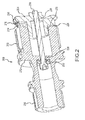
FIG. 2 illustrates various aspects of a coupling shaft assembly system according to various embodiments; -
FIG. 3 illustrates various aspects of a main coupling shaft body of a coupling shaft assembly system according to various embodiments; -
FIG. 4 illustrates various aspects of a coupling shaft spline lock body of a coupling shaft assembly system according to various embodiments; and -
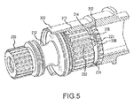
FIG. 5 illustrates a coupling shaft assembly system installed in mechanical communication with a power shaft according to various embodiments. - The detailed description of exemplary embodiments herein makes reference to the accompanying drawings, which show exemplary embodiments by way of illustration and their best mode. While these exemplary embodiments are described in sufficient detail to enable those skilled in the art to practice the inventions, it should be understood that other embodiments may be realized and that logical and mechanical changes may be made without departing from the scope of the disclosure. Thus, the detailed description herein is presented for purposes of illustration only and not of limitation. For example, the steps recited in any of the method or process descriptions may be executed in any order and are not necessarily limited to the order presented.
- Furthermore, any reference to singular includes plural embodiments, and any reference to more than one component or step may include a singular embodiment or step. Also, any reference to attached, fixed, connected or the like may include permanent, removable, temporary, partial, full and/or any other possible attachment option. Additionally, any reference to without contact (or similar phrases) may also include reduced contact or minimal contact.
- As used herein, phrases such as "make contact with," "coupled to," "touch," "interface with" and "engage" may be used interchangeably.
- In various embodiments, a load device may accept mechanical energy input via a load drive shaft. In various embodiments, a mechanical energy source may provide mechanical energy via a power shaft. A coupling system may transfer mechanical energy from the power shaft to the load drive shaft. A mechanical energy delivery system may comprise a load device comprising a load drive, a coupling shaft assembly system, and a mechanical energy source comprising a power shaft, wherein the coupling shaft assembly system mechanically interfaces with the power shaft to receive mechanical energy from the power shaft, and wherein the coupling shaft assembly system mechanically interfaces with the load drive shaft to transfer mechanical energy to the load drive shaft.
- For example, with reference to
Fig. 1 , a mechanical energy delivery system may comprisepower shaft 300, a couplingshaft assembly system 200, and aload drive shaft 100. In various embodiments, as described herein, couplingshaft assembly system 200 limits the transfer of axial loads among system components. For example, as further discussed, couplingshaft assembly system 200 may lock in substantially fixed axial position with respect to thepower shaft 300. As a result, in various embodiments, axial inertial movement of couplingshaft assembly system 200 may be limited. - For example, in various embodiments,
disconnect shaft 50 may mechanically interface withload drive shaft 100 via aface clutch 55. Disconnectshaft 50 may travel axially to mechanically connect and disconnect fromface clutch 55. In this manner, axial loads may transfer to loaddrive shaft 100, for example, as a result of the axial force ofdisconnect shaft 50 making and breaking contact withface clutch 55. Moreover, in various embodiments, axial loads may transfer to loaddrive shaft 100 from other sources, such as internal pressure differentials or hydraulic pressure on system components. Thus, axial loads may be transferred fromload drive shaft 100, into couplingshaft assembly system 200. In various embodiments, couplingshaft assembly system 200 may lock in substantially fixed axial position with respect to thepower shaft 300. As a result, axial reaction forces, and/or axial kinetic impulses, and/or relative axial movement between couplingshaft assembly system 200 andpower shaft 300 and/orload drive shaft 100 may be limited, for example, by preventing inertial movement of couplingshaft assembly system 200 and by facilitating more consistent axial load transfer from couplingshaft assembly system 200 topower shaft 300. - Similarly, axial loads may be transferred from
power shaft 300 to couplingshaft assembly system 200. For example, in various embodiments, other system components may impart an axial load onpower shaft 300. In this manner, axial loads may transfer to couplingshaft assembly system 200 and intoload drive shaft 100. In various embodiments, couplingshaft assembly system 200 may lock in substantially fixed axial position with respect to thepower shaft 300. As a result, axial reaction forces, and/or axial kinetic impulses, and/or relative axial movement between couplingshaft assembly system 200 andpower shaft 300 and/orload drive shaft 100 may be limited, for example by preventing inertial movement ofcoupling shaft assembly 200 and by facilitating more consistent axial load transfer frompower shaft 300 to couplingshaft assembly system 200. - In various embodiments, with reference to
Figs. 2-4 , a couplingshaft assembly system 200 may comprise a coupling shaftspline lock body 204, alocking bolt 208, and a maincoupling shaft body 212. In various embodiments, maincoupling shaft body 212 comprises anannular face 222 and coupling shaftspline lock body 204 comprises anannular face 224. In various embodiments, maincoupling shaft body 212 and coupling shaftspline lock body 204 abut so thatannular face 222 abutsannular face 224. Maincoupling shaft body 212 may comprise anaperture 226 through which lockingbolt 208 may extend. Coupling shaftspline lock body 204 may comprise acorresponding aperture 228 into which lockingbolt 208 extends. Lockingbolt 208 may retain maincoupling shaft body 212 and coupling shaftspline lock body 204 in mechanical communication, for example, via a fastener and/or an engagement structure. In various embodiments, an engagement structure may comprise mating threaded structures or self-locking helical coil inserts. An aperture and locking bolt may comprise mating threaded structures. For example, at least a portion ofaperture 228 is threaded to retainlocking bolt 208, which comprises a threaded portion configured to mate with the threaded portion ofaperture 228. In various embodiments,locking bolt 208 is retained by a retaining clip, or a nut, or a nut and washer, or any other fastening mechanism whereby lockingbolt 208 is retained. Moreover,aperture 226 comprises abolt seal 210 wherebyaperture 226 is sealed, for example, to prevent lubricating oil from escaping throughaperture 226. - In various embodiments, with continuing reference to
Fig. 2 , maincoupling shaft body 212 may compriseinput spline teeth 202. In this regard, the maincoupling shaft body 212 may mechanically interface with a mechanical energy source. In various embodiments, the maincoupling shaft body 212 may mechanically interface with apower shaft 300. For example, with momentary reference toFig. 5 ,input spline teeth 202 may interface withreceiver spline teeth 310 of apower shaft 300.Input spline teeth 202 may have a number, a thickness, and a height corresponding with thereceiver spline teeth 310 ofpower shaft 300. - In various embodiments, and with continuing reference to
Figs. 2-4 , maincoupling shaft body 212 also comprisesoutput spline teeth 230. In this regard, the maincoupling shaft body 212 may mechanically interface with a load device. In various embodiments, the maincoupling shaft body 212 may mechanically interface with aload drive shaft 100. For example,output spline teeth 230, may interface with corresponding spline teeth onload drive shaft 100. - In various embodiments, a coupling shaft
spline lock body 204 may comprise splinelock spline teeth 206. Splinelock spline teeth 206 may have a number, a thickness, and a height substantially equivalent to the number, thickness, and height ofinput spline teeth 202. In various embodiments, spline lockteeth 206 may have a number that is fewer thaninput spline teeth 202. In various embodiments, spline lockteeth 206 may have a number that is one-half that ofinput spline teeth 202. Moreover, in various embodiments, the thickness and/or height of splinelock spline teeth 206 may be less than the thickness and/or height ofinput spline teeth 202, for example to facilitate increased manufacturing tolerances. As will be discussed further herein, coupling shaftspline lock body 204 may lock couplingshaft assembly system 200 in substantially fixed axial position with respect to thepower shaft 300. In this manner, couplingshaft assembly system 200 may limit the transfer of axial loads among system components. - In various embodiments, with reference to
Fig. 3 , maincoupling shaft body 212 may also comprise aphasing tab 214. Aphasing tab 214 comprises a tab extending axially from the maincoupling shaft body 212, for example, fromannular face 222. In various embodiments, the tab may comprise a three-dimensional tab shaped to follow a circular arc having a constant radius less than that of theannular face 222 of the maincoupling shaft body 212. In various embodiments, the arc of the phasing tab may subtend an angle wherein the angle has a vertex coincident with the center ofannular face 222 of the maincoupling shaft body 212 and wherein the angle is less than 180 degrees. In various embodiments, the angle is 15 degrees, and in various embodiments the angle is between 5 and 175 degrees. In various embodiments, a maincoupling shaft body 212 may comprise two phasingtabs 214, or three phasingtabs 214 or any number of phasingtabs 214. Moreover, in various embodiments, phasingtab 214 may be round, for example, in various embodiments wherein phasingtab 214 comprises a pressed pin.Phasing tab 214 may be any shape and/or orientation adapted to interface with phasingslot 216 according to the principles disclosed herein. - In various embodiments, with reference to
Fig. 4 , coupling shaftspline lock body 204 may comprise aphasing slot 216. Phasingslot 216 may comprise a lockedportion 218 and anunlocked portion 220. With additional reference toFig. 5 , phasingslot 216 is configured so that phasingtab 214 may fit therein. Moreover, phasingslot 216 is configured so that phasingtab 214 may fit therein in two different configurations. For example, with continuing reference toFig. 5 , phasingslot 216 comprises a lockedportion 218 wherein phasingtab 214 may fit when the couplingshaft assembly system 200 is in the locked configuration, and comprises anunlocked portion 220 wherein phasingtab 214 is free to move when couplingshaft assembly system 200 is in the unlocked configuration. - In various embodiments, the locked
portion 218 of phasingslot 216 is located at a position along theannular face 224 of the coupling shaftspline lock body 204 so that when phasingtab 214 is fit within the lockedportion 218 of phasingslot 216, the splinelock spline teeth 206 are positioned out of phase with theinput spline teeth 202 of the maincoupling shaft body 212. In this regard, theinput spline teeth 202 and the splinelock spline teeth 206 are intentionally misaligned. - In various embodiments, the
unlocked portion 220 of phasingslot 216 is located at a position along theannular face 224 of the coupling shaftspline lock body 204 so that when phasingtab 214 is fit within theunlocked portion 220 of phasingslot 216, the splinelock spline teeth 206 are positioned in phase with theinput spline teeth 202 of the maincoupling shaft body 212. In this regard, theinput spline teeth 202 and the splinelock spline teeth 206 are intentionally aligned. - In various embodiments, a coupling shaft
spline lock body 204 may comprise two phasingslots 216, or three phasingslots 216, or any number of phasingslots 216 suitable to interface with phasingtabs 214. In various embodiments, there may bemore phasing slots 216 than phasingtabs 214. In various embodiments, coupling shaftspline lock body 204 may comprise phasingtabs 214 and the maincoupling shaft body 212 may comprise phasingslots 216. In various embodiments, coupling shaftspline lock body 204 may comprise both phasingtabs 214 and phasingslots 216 and maincoupling shaft body 212 may comprise both phasingtabs 214 and phasingslots 216. Thus, various components of couplingshaft assembly system 200 may comprise any combination or number of phasingtabs 214 and phasingslots 216 suitable to permit couplingshaft assembly system 200 to operate according to the principles disclosed herein. - Now, having described the various components of a coupling
shaft assembly system 200, a coupling shaft assembly system may be installed according to various methods. For example, the lockingbolt 208 may be loosened so that the coupling shaftspline lock body 204 and the maincoupling shaft body 212 are not held in fixed position, but can rotate annularly about the axis provided by the lockingbolt 208. In this regard, couplingshaft assembly system 200 may be put in the unlocked configuration, so that phasingtab 214 may enter theunlocked portion 220 of thephasing slot 216. With reference toFig. 5 , the couplingshaft assembly system 200 may be inserted into apower shaft 300 and theinput spline teeth 202 inserted into thereceiver spline teeth 310. The splinelock spline teeth 206 may be passed through thereceiver spline teeth 310 and may reside in areceiver channel 312. Thelocking bolt 208 may then be tightened, drawing the coupling shaftspline lock body 204 and the maincoupling shaft body 212 together and causingphasing tab 214 to enter lockedportion 218 of thephasing slot 216. Thus,annular face 224 of coupling shaftspline lock body 204 may be pressed in substantially fixed communication withannular face 222 of maincoupling shaft body 212. In various embodiments, the lockingbolt 208 is tightened inertially, for example, by inertial movement of coupling shaftspline lock body 204 and/or lockingbolt 208 relative to the maincoupling shaft body 212 upon rotational acceleration of the couplingshaft assembly system 200. In this regard, it may be said that thelocking bolt 208 is tightened by the "rundown torque" of the coupling shaftspline lock body 204 and/or thelocking bolt 208. - Moreover, as phasing
tab 214 seats within lockedportion 218 of phasingslot 216, the coupling shaftspline lock body 204 is prevented from rotating annularly about the axis provided by the lockingbolt 208 so that the splinelock spline teeth 206 are positioned out of phase with theinput spline teeth 202 of the maincoupling shaft body 212. In this regard, the splinelock spline teeth 206 are prevented from exiting thereceiver channel 312 due to the intentional interference with thereceiver spline teeth 310 caused by the phase angle between the splinelock spline teeth 206 and theinput spline teeth 202. Thus, coupling shaftspline lock body 204 may lock couplingshaft assembly system 200 in substantially fixed mechanical communication withpower shaft 300. In various embodiments, the locking of couplingshaft assembly system 200 in substantially fixed mechanical communication withpower shaft 300 reduces the transfer of axial loading to other system components, for example, by dampening axial movement of the couplingshaft assembly system 200. In various embodiments, the range of axial movement of couplingshaft assembly system 200 is limited to approximately the clearance betweenreceiver channel 312 and splinelock spline teeth 206. - Now, having described various components of coupling shaft assembly systems and methods of installing coupling shaft assembly system, a coupling shaft assembly system may be manufactured from various materials. In various embodiments, a coupling shaft assembly system may comprise steel and/or stainless steel. However, in further embodiments, a coupling shaft assembly system may comprise other metals, such as aluminum, titanium, tungsten, or copper, though it may further comprise numerous other materials configured to provide durability under load. In various embodiments, various portions of coupling shaft assembly systems as disclosed herein are made of different materials or combinations of materials, and/or may comprise coatings.
- In various embodiments, coupling shaft assembly systems may comprise multiple materials, or any material configuration suitable to enhance or reinforce the resiliency and/or support of the system when subjected to wear in an operating environment or to satisfy other desired electromagnetic, chemical, physical, or biological properties such as mass, elasticity, conductivity, and operating temperature range, among others.
- In various embodiments, one will appreciate in light of the present disclosure, that the coupling shaft assembly systems described herein may be used on various applications such as, for example, aircraft generator systems, power train systems, industrial systems or processes, vehicle drive systems, power generation systems, power takeoff ("PTO") systems, and other systems or processes. Moreover, the coupling shaft assembly systems described herein may be employed with any mechanical energy source in any installation. In various embodiments, the coupling shaft assembly systems described herein are used in the context of a generator for use in an aircraft. Thus, in various embodiments, the coupling shaft assembly systems described herein provide cost effective and reliable mechanical energy transfer. Furthermore, the coupling shaft assembly systems described herein may be utilized to eliminate the need for an accessory blanking plate when a load device is disconnected from a mechanical energy source. For example, the coupling shaft assembly system may be locked in substantially fixed axial position with respect to another shaft to ameliorate the risk of dirt or other foreign objects entering.
- Benefits, other advantages, and solutions to problems have been described herein with regard to specific embodiments. Furthermore, the connecting lines shown in the various figures contained herein are intended to represent exemplary functional relationships and/or physical couplings between the various elements. It should be noted that many alternative or additional functional relationships or physical connections may be present in a practical system. However, the benefits, advantages, solutions to problems, and any elements that may cause any benefit, advantage, or solution to occur or become more pronounced are not to be construed as critical, required, or essential features or elements of the inventions. The scope of the inventions is accordingly to be limited by nothing other than the appended claims, in which reference to an element in the singular is not intended to mean "one and only one" unless explicitly so stated, but rather "one or more." Moreover, where a phrase similar to "at least one of A, B, or C" is used in the claims, it is intended that the phrase be interpreted to mean that A alone may be present in an embodiment, B alone may be present in an embodiment, C alone may be present in an embodiment, or that any combination of the elements A, B and C may be present in a single embodiment; for example, A and B, A and C, B and C, or A and B and C.
- Systems, methods and apparatus are provided herein. In the detailed description herein, references to "one embodiment", "an embodiment", "various embodiments", etc., indicate that the embodiment described may include a particular feature, structure, or characteristic, but every embodiment may not necessarily include the particular feature, structure, or characteristic. Moreover, such phrases are not necessarily referring to the same embodiment. Further, when a particular feature, structure, or characteristic is described in connection with an embodiment, it is submitted that it is within the knowledge of one skilled in the art to affect such feature, structure, or characteristic in connection with other embodiments whether or not explicitly described. After reading the description, it will be apparent to one skilled in the relevant art(s) how to implement the disclosure in alternative embodiments.
- Furthermore, no element, component, or method step in the present disclosure is intended to be dedicated to the public regardless of whether the element, component, or method step is explicitly recited in the claims. No claim element herein is to be construed under the provisions of 35 U.S.C. 112(f), unless the element is expressly recited using the phrase "means for." As used herein, the terms "comprises", "comprising", or any other variation thereof, are intended to cover a non-exclusive inclusion, such that a process, method, article, or apparatus that comprises a list of elements does not include only those elements but may include other elements not expressly listed or inherent to such process, method, article, or apparatus.
Claims (15)
- A coupling shaft assembly system (200) comprising:a coupling shaft spline lock body (204) comprising spline lock spline teeth (206);a main coupling shaft body (212) comprising input spline teeth (202);a locking bolt (208),wherein the locking bolt (208) retains the coupling shaft spline lock body (204) in substantially fixed communication with the main coupling shaft body (212),wherein the coupling shaft spline lock body (204) retains the coupling shaft assembly system (200) in mechanical communication with a power shaft (300).
- The coupling shaft assembly system according to claim 1, wherein the spline lock spline teeth (206) and the input spline teeth (202) are present in at least one of a 1:1 ratio and a 1:2 ratio.
- The coupling shaft assembly system according to claim 1 or 2, further comprising a bolt seal (210) surrounding the locking bolt (208) and positioned around an aperture (236) of the main coupling shaft body (212).
- The coupling shaft assembly system according to claim 1, 2 or 3, wherein the coupling shaft spline lock body (204) further comprises a phasing slot (216), wherein the main coupling shaft body (212) further comprises a phasing tab (214), wherein the phasing slot (216) comprises a locked portion (218) and an unlocked portion (220), and wherein the phasing tab (214) is inserted into the phasing slot (216).
- The coupling shaft assembly system according to claim 4, wherein the locked portion (218) comprises a recess shaped to accept the phasing tab (214).
- The coupling shaft assembly system according to claim 4 or 5, wherein the phasing tab (214) is shaped to follow a circular arc having a constant radius less than that of the main coupling shaft body (212) wherein the arc of the phasing tab (214) subtends an angle wherein the angle has a vertex coincident with a central axis of the main coupling shaft body (212).
- The coupling shaft assembly system according to claim 4, 5 or 6, wherein the phasing tab (214) inserts into the locked portion (218) of the phasing slot (216), and wherein, in response to the phasing tab (214) being in the locked portion (218) of the phasing slot (216), the input spline teeth (202) and the spline lock spline teeth (206) are misaligned.
- The coupling shaft assembly system according to any of claims 4 to 7, wherein the phasing tab (214) is free to move within the unlocked portion (220) of the phasing slot (216), and wherein in response to the phasing tab (214) being in the unlocked portion (220) of the phasing slot (216), the input spline teeth (202) and the spline lock spline teeth (206) are aligned.
- The coupling shaft assembly system according to any of claims 4 to 8, further comprising a second phasing slot and/or further comprising a second phasing tab.
- A method of installing a coupling shaft assembly system (200) comprising:annularly rotating a coupling shaft spline lock body (204) comprising spline lock spline teeth (206) and a phasing slot (216) with respect to a main coupling shaft body (212) comprising input spline teeth (202) and a phasing tab (214) so that the input spline teeth (202) are aligned in phase with the spline lock spline teeth (206);inserting the coupling shaft assembly system (200) into an aperture of a power shaft (300) comprising receiver splines (310) and a receiver channel (312),wherein the input spline teeth (202) are inserted in mechanical communication with the receiver splines (310), andwherein the spline lock spline teeth (206) are inserted through the receiver splines (310) and into the receiver channel (312);annularly rotating the coupling shaft spline lock body (204) with respect to the main coupling shaft body (212) so that the input spline teeth (202) are misaligned with the spline lock spline teeth (206) whereby the input spline teeth (202) are out of phase with the spline lock spline teeth (206);tightening a locking bolt (208) whereby the coupling shaft spline lock body (204) and the main coupling shaft body (212) are drawn together in substantially fixed communication and the phasing tab (214) seats in the phasing slot (216).
- The method of claim 10, wherein the tightening a locking bolt (208) comprises:rotating the coupling shaft assembly system (200);transmitting an inertial torque to the locking bolt (208) in response to the rotating; androtating the locking bolt (208) in response to the torque.
- The method of claim 10 or 11, wherein the phasing slot (216) comprises a locked portion (218) and an unlocked portion (220), wherein the tightening the locking bolt (208) further causes the coupling shaft spline lock body (204) to rotate with respect to the main coupling shaft body (212) and causes the phasing tab (214) to move from the unlocked portion (220) of the phasing slot (216) to the locked portion (218) of the phasing slot (216).
- The method of claim 12, wherein the causing the phasing tab (214) to move from the unlocked portion (220) of the phasing slot (216) further comprises seating the phasing tab (214) more deeply in the phasing slot (216).
- The method of any of claims 10 to 13, further comprising:limiting axial movement of the coupling shaft assembly system (200) in response to the inserting the spline lock spline teeth (206) through the receiver splines (310) and into the receiver channel (312); andreducing the transfer of an axial load by the coupling shaft assembly system (200) in response to the limitation.
- The method of any of claims 10 to 14, further comprising:loosening a locking bolt (208) retaining a coupling shaft spline lock body (204) comprising spline lock spline teeth (206) in substantially fixed communication with a main coupling shaft body (212) comprising input spline teeth (202); andspinning the coupling shaft assembly system (200) whereby the power shaft (300) transfers mechanical energy to a load drive shaft (100).
Applications Claiming Priority (1)
| Application Number | Priority Date | Filing Date | Title |
|---|---|---|---|
| US14/149,448 US9476459B2 (en) | 2014-01-07 | 2014-01-07 | Spline lock shaft locking system |
Publications (3)
| Publication Number | Publication Date |
|---|---|
| EP2913550A2 true EP2913550A2 (en) | 2015-09-02 |
| EP2913550A3 EP2913550A3 (en) | 2015-12-09 |
| EP2913550B1 EP2913550B1 (en) | 2019-03-06 |
Family
ID=52292763
Family Applications (1)
| Application Number | Title | Priority Date | Filing Date |
|---|---|---|---|
| EP15150200.2A Active EP2913550B1 (en) | 2014-01-07 | 2015-01-06 | Spline lock shaft locking system |
Country Status (2)
| Country | Link |
|---|---|
| US (1) | US9476459B2 (en) |
| EP (1) | EP2913550B1 (en) |
Cited By (1)
| Publication number | Priority date | Publication date | Assignee | Title |
|---|---|---|---|---|
| US10465758B2 (en) | 2017-07-26 | 2019-11-05 | Ingersoll-Rand Company | Rotatable shaft with fluid actuated lock piston |
Families Citing this family (6)
| Publication number | Priority date | Publication date | Assignee | Title |
|---|---|---|---|---|
| CN107023585B (en) * | 2016-02-02 | 2020-11-03 | 索恩格汽车部件(中国)有限公司 | Spline connection structure reaches engine starting motor including it |
| FR3075879B1 (en) * | 2017-12-22 | 2019-11-15 | Safran Aircraft Engines | TREE ASSEMBLY FOR AN AIRCRAFT TURBOMACHINE |
| US11143309B2 (en) | 2018-10-09 | 2021-10-12 | Hamilton Sundstrand Corporation | Disconnect bearing and input seal for a variable frequency starter generator |
| US11821468B2 (en) | 2018-11-08 | 2023-11-21 | Pratt & Whitney Canada Corp. | Positioning device and method for shafts |
| US12570383B1 (en) * | 2022-01-19 | 2026-03-10 | Brunswick Corporation | Systems and methods for optimizing driveshaft coupling of marine propulsion device |
| US12228082B2 (en) | 2022-05-25 | 2025-02-18 | Hamilton Sundstrand Corporation | Splined shaft assembly with piloting features |
Family Cites Families (25)
| Publication number | Priority date | Publication date | Assignee | Title |
|---|---|---|---|---|
| JPS5393241A (en) * | 1977-01-26 | 1978-08-16 | Aisin Seiki Co Ltd | Car free wheel hub |
| SE399745B (en) * | 1977-03-31 | 1978-02-27 | Skf Nova Ab | LOADING DEVICE |
| US4281942A (en) * | 1978-11-13 | 1981-08-04 | General Electric Company | Lubrication system for high speed spline connection and bearing |
| US4215586A (en) * | 1979-02-01 | 1980-08-05 | Morris Charles M | Truck transmission with power take-off |
| DE3320444C1 (en) | 1983-06-06 | 1987-10-01 | Danfoss A/S, Nordborg | Coupling for connecting a hub and a shaft |
| BR8305573A (en) * | 1983-10-10 | 1985-05-14 | Avm Auto Equip | IMPROVEMENT IN OPTIONAL VEHICLE TRACTION WHEEL RELEASE DEVICE |
| US4657428A (en) * | 1985-09-10 | 1987-04-14 | Wiley Edward R | Quick change mechanism for circular saw blades and other spinning disc devices |
| US4730952A (en) * | 1986-08-04 | 1988-03-15 | Wiley Edward R | Quick change mechanism for circular saw blades |
| US4810126A (en) * | 1988-07-05 | 1989-03-07 | Allied-Signal Inc. | Compact oil slinger and spring loaded retention device |
| FR2661231B1 (en) * | 1990-04-19 | 1992-07-03 | Hispano Suiza Sa | DEVICE FOR SEALING DRIVE SHAFTS WITH INTERNAL SPLINES. |
| LU88623A1 (en) * | 1995-06-12 | 1997-01-03 | Wurth Paul Sa | Closing unit for an injection molding machine |
| US6607044B1 (en) * | 1997-10-27 | 2003-08-19 | Halliburton Energy Services, Inc. | Three dimensional steerable system and method for steering bit to drill borehole |
| US6193241B1 (en) * | 1999-05-24 | 2001-02-27 | Thomas R. Vigil | Tool drive system |
| KR100851578B1 (en) * | 2000-08-29 | 2008-08-12 | 가부시키카이샤 나브코 | Drive unit |
| GB0101859D0 (en) * | 2001-01-24 | 2001-03-07 | Lucas Industries Ltd | A thermal disconnect device |
| US7047848B2 (en) * | 2001-06-29 | 2006-05-23 | Portar-Cable/Delta | Manufacture of steel components for screw gun clutches |
| US6742640B1 (en) * | 2002-01-11 | 2004-06-01 | Torque-Traction Technologies, Inc. | Wrap spring activated torque transfer device |
| GB0412203D0 (en) * | 2004-06-01 | 2004-07-07 | Goodrich Control Sys Ltd | Disconnect mechanism and devices including such a disconnect mechanism |
| US7306535B2 (en) * | 2004-06-29 | 2007-12-11 | Delphi Technologies, Inc. | Vehicle steering device and method |
| US20070180705A1 (en) * | 2006-02-08 | 2007-08-09 | Yi-Shan Chiu | Locking device for spline shaft of brush cutter |
| DE102007008837A1 (en) * | 2007-02-23 | 2008-08-28 | Esa Eppinger Gmbh | Coupling device for tool holders or workpiece clamping devices |
| EP2403685B1 (en) * | 2008-01-07 | 2015-05-06 | Lachlan George Reid | Attachment mechanism for a cutting disc |
| CN201846188U (en) * | 2010-10-09 | 2011-05-25 | 德昌电机(深圳)有限公司 | Starter and starting motor device |
| BRMU9100610U2 (en) * | 2011-03-18 | 2014-03-25 | Zen S A Ind Metalurgica | PROVISION APPLIED ON A STARTING UNIT THAT WORKS CONSTANTLY GEARED TO THE MAIN ENGINE |
| US20120251234A1 (en) * | 2011-03-31 | 2012-10-04 | Lemmers Jr Glenn C | Connection device for drive assembly |
-
2014
- 2014-01-07 US US14/149,448 patent/US9476459B2/en active Active
-
2015
- 2015-01-06 EP EP15150200.2A patent/EP2913550B1/en active Active
Non-Patent Citations (1)
| Title |
|---|
| None |
Cited By (1)
| Publication number | Priority date | Publication date | Assignee | Title |
|---|---|---|---|---|
| US10465758B2 (en) | 2017-07-26 | 2019-11-05 | Ingersoll-Rand Company | Rotatable shaft with fluid actuated lock piston |
Also Published As
| Publication number | Publication date |
|---|---|
| EP2913550B1 (en) | 2019-03-06 |
| US9476459B2 (en) | 2016-10-25 |
| EP2913550A3 (en) | 2015-12-09 |
| US20150192177A1 (en) | 2015-07-09 |
Similar Documents
| Publication | Publication Date | Title |
|---|---|---|
| EP2913550B1 (en) | Spline lock shaft locking system | |
| EP2392477B1 (en) | Spindle nut | |
| EP1924800B1 (en) | Self-locking self-bonding rigid coupling | |
| US6086400A (en) | Self-locking cable connector coupling | |
| US10180166B2 (en) | Disconnect mechanisms | |
| EP2799729A1 (en) | Nut and sleeve fastener | |
| JP6774491B2 (en) | Electrical connector and connection method | |
| EP3021465B1 (en) | Resettable electro-mechanically actuated connection unit for generators | |
| US4810126A (en) | Compact oil slinger and spring loaded retention device | |
| EP3963221B1 (en) | A hub lock nut assembly | |
| EP2505860A2 (en) | Connection device for drive assembly | |
| US20200224700A1 (en) | Snap ring having retention feature | |
| WO2018158251A1 (en) | Power screw mechanism with rotation clutch | |
| US20080179155A1 (en) | Drive system for a motor vehicle | |
| CN106481697A (en) | Brake unit and the Linear actuator using this brake unit | |
| EP3751159B1 (en) | Lockwireless rod assembly | |
| EP1819590B1 (en) | Coupling for a propulsion system | |
| US20230198203A1 (en) | Electric Connector with an Anti-Vibration Mechanism | |
| EP3790122A1 (en) | Multi-lock counter connector | |
| US20260029052A1 (en) | Dual drive gear shift assembly for vehicle gearbox | |
| US10138926B2 (en) | Telescoping torque tube assembly |
Legal Events
| Date | Code | Title | Description |
|---|---|---|---|
| PUAI | Public reference made under article 153(3) epc to a published international application that has entered the european phase |
Free format text: ORIGINAL CODE: 0009012 |
|
| AK | Designated contracting states |
Kind code of ref document: A2 Designated state(s): AL AT BE BG CH CY CZ DE DK EE ES FI FR GB GR HR HU IE IS IT LI LT LU LV MC MK MT NL NO PL PT RO RS SE SI SK SM TR |
|
| AX | Request for extension of the european patent |
Extension state: BA ME |
|
| PUAL | Search report despatched |
Free format text: ORIGINAL CODE: 0009013 |
|
| AK | Designated contracting states |
Kind code of ref document: A3 Designated state(s): AL AT BE BG CH CY CZ DE DK EE ES FI FR GB GR HR HU IE IS IT LI LT LU LV MC MK MT NL NO PL PT RO RS SE SI SK SM TR |
|
| AX | Request for extension of the european patent |
Extension state: BA ME |
|
| RIC1 | Information provided on ipc code assigned before grant |
Ipc: F16D 1/10 20060101AFI20151104BHEP Ipc: F16D 1/108 20060101ALI20151104BHEP Ipc: F16D 1/04 20060101ALI20151104BHEP |
|
| 17P | Request for examination filed |
Effective date: 20160607 |
|
| RBV | Designated contracting states (corrected) |
Designated state(s): AL AT BE BG CH CY CZ DE DK EE ES FI FR GB GR HR HU IE IS IT LI LT LU LV MC MK MT NL NO PL PT RO RS SE SI SK SM TR |
|
| GRAP | Despatch of communication of intention to grant a patent |
Free format text: ORIGINAL CODE: EPIDOSNIGR1 |
|
| STAA | Information on the status of an ep patent application or granted ep patent |
Free format text: STATUS: GRANT OF PATENT IS INTENDED |
|
| RIC1 | Information provided on ipc code assigned before grant |
Ipc: F16D 1/10 20060101AFI20180815BHEP Ipc: F16D 1/108 20060101ALI20180815BHEP Ipc: F16D 1/116 20060101ALI20180815BHEP Ipc: F16D 1/04 20060101ALI20180815BHEP |
|
| INTG | Intention to grant announced |
Effective date: 20180913 |
|
| GRAS | Grant fee paid |
Free format text: ORIGINAL CODE: EPIDOSNIGR3 |
|
| GRAA | (expected) grant |
Free format text: ORIGINAL CODE: 0009210 |
|
| STAA | Information on the status of an ep patent application or granted ep patent |
Free format text: STATUS: THE PATENT HAS BEEN GRANTED |
|
| AK | Designated contracting states |
Kind code of ref document: B1 Designated state(s): AL AT BE BG CH CY CZ DE DK EE ES FI FR GB GR HR HU IE IS IT LI LT LU LV MC MK MT NL NO PL PT RO RS SE SI SK SM TR |
|
| REG | Reference to a national code |
Ref country code: GB Ref legal event code: FG4D |
|
| REG | Reference to a national code |
Ref country code: CH Ref legal event code: EP Ref country code: AT Ref legal event code: REF Ref document number: 1104963 Country of ref document: AT Kind code of ref document: T Effective date: 20190315 |
|
| REG | Reference to a national code |
Ref country code: DE Ref legal event code: R096 Ref document number: 602015025671 Country of ref document: DE |
|
| REG | Reference to a national code |
Ref country code: IE Ref legal event code: FG4D |
|
| REG | Reference to a national code |
Ref country code: NL Ref legal event code: MP Effective date: 20190306 |
|
| REG | Reference to a national code |
Ref country code: LT Ref legal event code: MG4D |
|
| PG25 | Lapsed in a contracting state [announced via postgrant information from national office to epo] |
Ref country code: SE Free format text: LAPSE BECAUSE OF FAILURE TO SUBMIT A TRANSLATION OF THE DESCRIPTION OR TO PAY THE FEE WITHIN THE PRESCRIBED TIME-LIMIT Effective date: 20190306 Ref country code: FI Free format text: LAPSE BECAUSE OF FAILURE TO SUBMIT A TRANSLATION OF THE DESCRIPTION OR TO PAY THE FEE WITHIN THE PRESCRIBED TIME-LIMIT Effective date: 20190306 Ref country code: NO Free format text: LAPSE BECAUSE OF FAILURE TO SUBMIT A TRANSLATION OF THE DESCRIPTION OR TO PAY THE FEE WITHIN THE PRESCRIBED TIME-LIMIT Effective date: 20190606 Ref country code: LT Free format text: LAPSE BECAUSE OF FAILURE TO SUBMIT A TRANSLATION OF THE DESCRIPTION OR TO PAY THE FEE WITHIN THE PRESCRIBED TIME-LIMIT Effective date: 20190306 |
|
| PG25 | Lapsed in a contracting state [announced via postgrant information from national office to epo] |
Ref country code: GR Free format text: LAPSE BECAUSE OF FAILURE TO SUBMIT A TRANSLATION OF THE DESCRIPTION OR TO PAY THE FEE WITHIN THE PRESCRIBED TIME-LIMIT Effective date: 20190607 Ref country code: HR Free format text: LAPSE BECAUSE OF FAILURE TO SUBMIT A TRANSLATION OF THE DESCRIPTION OR TO PAY THE FEE WITHIN THE PRESCRIBED TIME-LIMIT Effective date: 20190306 Ref country code: LV Free format text: LAPSE BECAUSE OF FAILURE TO SUBMIT A TRANSLATION OF THE DESCRIPTION OR TO PAY THE FEE WITHIN THE PRESCRIBED TIME-LIMIT Effective date: 20190306 Ref country code: NL Free format text: LAPSE BECAUSE OF FAILURE TO SUBMIT A TRANSLATION OF THE DESCRIPTION OR TO PAY THE FEE WITHIN THE PRESCRIBED TIME-LIMIT Effective date: 20190306 Ref country code: BG Free format text: LAPSE BECAUSE OF FAILURE TO SUBMIT A TRANSLATION OF THE DESCRIPTION OR TO PAY THE FEE WITHIN THE PRESCRIBED TIME-LIMIT Effective date: 20190606 Ref country code: RS Free format text: LAPSE BECAUSE OF FAILURE TO SUBMIT A TRANSLATION OF THE DESCRIPTION OR TO PAY THE FEE WITHIN THE PRESCRIBED TIME-LIMIT Effective date: 20190306 |
|
| REG | Reference to a national code |
Ref country code: AT Ref legal event code: MK05 Ref document number: 1104963 Country of ref document: AT Kind code of ref document: T Effective date: 20190306 |
|
| PG25 | Lapsed in a contracting state [announced via postgrant information from national office to epo] |
Ref country code: CZ Free format text: LAPSE BECAUSE OF FAILURE TO SUBMIT A TRANSLATION OF THE DESCRIPTION OR TO PAY THE FEE WITHIN THE PRESCRIBED TIME-LIMIT Effective date: 20190306 Ref country code: RO Free format text: LAPSE BECAUSE OF FAILURE TO SUBMIT A TRANSLATION OF THE DESCRIPTION OR TO PAY THE FEE WITHIN THE PRESCRIBED TIME-LIMIT Effective date: 20190306 Ref country code: IT Free format text: LAPSE BECAUSE OF FAILURE TO SUBMIT A TRANSLATION OF THE DESCRIPTION OR TO PAY THE FEE WITHIN THE PRESCRIBED TIME-LIMIT Effective date: 20190306 Ref country code: EE Free format text: LAPSE BECAUSE OF FAILURE TO SUBMIT A TRANSLATION OF THE DESCRIPTION OR TO PAY THE FEE WITHIN THE PRESCRIBED TIME-LIMIT Effective date: 20190306 Ref country code: ES Free format text: LAPSE BECAUSE OF FAILURE TO SUBMIT A TRANSLATION OF THE DESCRIPTION OR TO PAY THE FEE WITHIN THE PRESCRIBED TIME-LIMIT Effective date: 20190306 Ref country code: PT Free format text: LAPSE BECAUSE OF FAILURE TO SUBMIT A TRANSLATION OF THE DESCRIPTION OR TO PAY THE FEE WITHIN THE PRESCRIBED TIME-LIMIT Effective date: 20190706 Ref country code: AL Free format text: LAPSE BECAUSE OF FAILURE TO SUBMIT A TRANSLATION OF THE DESCRIPTION OR TO PAY THE FEE WITHIN THE PRESCRIBED TIME-LIMIT Effective date: 20190306 Ref country code: SK Free format text: LAPSE BECAUSE OF FAILURE TO SUBMIT A TRANSLATION OF THE DESCRIPTION OR TO PAY THE FEE WITHIN THE PRESCRIBED TIME-LIMIT Effective date: 20190306 |
|
| PG25 | Lapsed in a contracting state [announced via postgrant information from national office to epo] |
Ref country code: PL Free format text: LAPSE BECAUSE OF FAILURE TO SUBMIT A TRANSLATION OF THE DESCRIPTION OR TO PAY THE FEE WITHIN THE PRESCRIBED TIME-LIMIT Effective date: 20190306 Ref country code: SM Free format text: LAPSE BECAUSE OF FAILURE TO SUBMIT A TRANSLATION OF THE DESCRIPTION OR TO PAY THE FEE WITHIN THE PRESCRIBED TIME-LIMIT Effective date: 20190306 |
|
| REG | Reference to a national code |
Ref country code: DE Ref legal event code: R097 Ref document number: 602015025671 Country of ref document: DE |
|
| PG25 | Lapsed in a contracting state [announced via postgrant information from national office to epo] |
Ref country code: AT Free format text: LAPSE BECAUSE OF FAILURE TO SUBMIT A TRANSLATION OF THE DESCRIPTION OR TO PAY THE FEE WITHIN THE PRESCRIBED TIME-LIMIT Effective date: 20190306 Ref country code: IS Free format text: LAPSE BECAUSE OF FAILURE TO SUBMIT A TRANSLATION OF THE DESCRIPTION OR TO PAY THE FEE WITHIN THE PRESCRIBED TIME-LIMIT Effective date: 20190706 |
|
| PLBE | No opposition filed within time limit |
Free format text: ORIGINAL CODE: 0009261 |
|
| STAA | Information on the status of an ep patent application or granted ep patent |
Free format text: STATUS: NO OPPOSITION FILED WITHIN TIME LIMIT |
|
| PG25 | Lapsed in a contracting state [announced via postgrant information from national office to epo] |
Ref country code: DK Free format text: LAPSE BECAUSE OF FAILURE TO SUBMIT A TRANSLATION OF THE DESCRIPTION OR TO PAY THE FEE WITHIN THE PRESCRIBED TIME-LIMIT Effective date: 20190306 |
|
| 26N | No opposition filed |
Effective date: 20191209 |
|
| PG25 | Lapsed in a contracting state [announced via postgrant information from national office to epo] |
Ref country code: SI Free format text: LAPSE BECAUSE OF FAILURE TO SUBMIT A TRANSLATION OF THE DESCRIPTION OR TO PAY THE FEE WITHIN THE PRESCRIBED TIME-LIMIT Effective date: 20190306 |
|
| PG25 | Lapsed in a contracting state [announced via postgrant information from national office to epo] |
Ref country code: TR Free format text: LAPSE BECAUSE OF FAILURE TO SUBMIT A TRANSLATION OF THE DESCRIPTION OR TO PAY THE FEE WITHIN THE PRESCRIBED TIME-LIMIT Effective date: 20190306 |
|
| REG | Reference to a national code |
Ref country code: DE Ref legal event code: R119 Ref document number: 602015025671 Country of ref document: DE |
|
| PG25 | Lapsed in a contracting state [announced via postgrant information from national office to epo] |
Ref country code: MC Free format text: LAPSE BECAUSE OF FAILURE TO SUBMIT A TRANSLATION OF THE DESCRIPTION OR TO PAY THE FEE WITHIN THE PRESCRIBED TIME-LIMIT Effective date: 20190306 |
|
| REG | Reference to a national code |
Ref country code: CH Ref legal event code: PL |
|
| REG | Reference to a national code |
Ref country code: BE Ref legal event code: MM Effective date: 20200131 |
|
| PG25 | Lapsed in a contracting state [announced via postgrant information from national office to epo] |
Ref country code: DE Free format text: LAPSE BECAUSE OF NON-PAYMENT OF DUE FEES Effective date: 20200801 Ref country code: LU Free format text: LAPSE BECAUSE OF NON-PAYMENT OF DUE FEES Effective date: 20200106 |
|
| PG25 | Lapsed in a contracting state [announced via postgrant information from national office to epo] |
Ref country code: BE Free format text: LAPSE BECAUSE OF NON-PAYMENT OF DUE FEES Effective date: 20200131 Ref country code: LI Free format text: LAPSE BECAUSE OF NON-PAYMENT OF DUE FEES Effective date: 20200131 Ref country code: CH Free format text: LAPSE BECAUSE OF NON-PAYMENT OF DUE FEES Effective date: 20200131 |
|
| PG25 | Lapsed in a contracting state [announced via postgrant information from national office to epo] |
Ref country code: IE Free format text: LAPSE BECAUSE OF NON-PAYMENT OF DUE FEES Effective date: 20200106 |
|
| PG25 | Lapsed in a contracting state [announced via postgrant information from national office to epo] |
Ref country code: MT Free format text: LAPSE BECAUSE OF FAILURE TO SUBMIT A TRANSLATION OF THE DESCRIPTION OR TO PAY THE FEE WITHIN THE PRESCRIBED TIME-LIMIT Effective date: 20190306 Ref country code: CY Free format text: LAPSE BECAUSE OF FAILURE TO SUBMIT A TRANSLATION OF THE DESCRIPTION OR TO PAY THE FEE WITHIN THE PRESCRIBED TIME-LIMIT Effective date: 20190306 |
|
| PG25 | Lapsed in a contracting state [announced via postgrant information from national office to epo] |
Ref country code: MK Free format text: LAPSE BECAUSE OF FAILURE TO SUBMIT A TRANSLATION OF THE DESCRIPTION OR TO PAY THE FEE WITHIN THE PRESCRIBED TIME-LIMIT Effective date: 20190306 |
|
| P01 | Opt-out of the competence of the unified patent court (upc) registered |
Effective date: 20230522 |
|
| PGFP | Annual fee paid to national office [announced via postgrant information from national office to epo] |
Ref country code: GB Payment date: 20251220 Year of fee payment: 12 |
|
| PGFP | Annual fee paid to national office [announced via postgrant information from national office to epo] |
Ref country code: FR Payment date: 20251217 Year of fee payment: 12 |